WO2015186310A1 - 運転支援装置 - Google Patents
運転支援装置 Download PDFInfo
- Publication number
- WO2015186310A1 WO2015186310A1 PCT/JP2015/002633 JP2015002633W WO2015186310A1 WO 2015186310 A1 WO2015186310 A1 WO 2015186310A1 JP 2015002633 W JP2015002633 W JP 2015002633W WO 2015186310 A1 WO2015186310 A1 WO 2015186310A1
- Authority
- WO
- WIPO (PCT)
- Prior art keywords
- pattern
- display
- range
- unit
- overcoming
- Prior art date
- Legal status (The legal status is an assumption and is not a legal conclusion. Google has not performed a legal analysis and makes no representation as to the accuracy of the status listed.)
- Ceased
Links
Images





Classifications
-
- G—PHYSICS
- G01—MEASURING; TESTING
- G01C—MEASURING DISTANCES, LEVELS OR BEARINGS; SURVEYING; NAVIGATION; GYROSCOPIC INSTRUMENTS; PHOTOGRAMMETRY OR VIDEOGRAMMETRY
- G01C21/00—Navigation; Navigational instruments not provided for in groups G01C1/00 - G01C19/00
- G01C21/26—Navigation; Navigational instruments not provided for in groups G01C1/00 - G01C19/00 specially adapted for navigation in a road network
- G01C21/34—Route searching; Route guidance
- G01C21/3453—Special cost functions, i.e. other than distance or default speed limit of road segments
- G01C21/3484—Personalized, e.g. from learned user behaviour or user-defined profiles
-
- B—PERFORMING OPERATIONS; TRANSPORTING
- B60—VEHICLES IN GENERAL
- B60K—ARRANGEMENT OR MOUNTING OF PROPULSION UNITS OR OF TRANSMISSIONS IN VEHICLES; ARRANGEMENT OR MOUNTING OF PLURAL DIVERSE PRIME-MOVERS IN VEHICLES; AUXILIARY DRIVES FOR VEHICLES; INSTRUMENTATION OR DASHBOARDS FOR VEHICLES; ARRANGEMENTS IN CONNECTION WITH COOLING, AIR INTAKE, GAS EXHAUST OR FUEL SUPPLY OF PROPULSION UNITS IN VEHICLES
- B60K35/00—Instruments specially adapted for vehicles; Arrangement of instruments in or on vehicles
- B60K35/10—Input arrangements, i.e. from user to vehicle, associated with vehicle functions or specially adapted therefor
-
- B—PERFORMING OPERATIONS; TRANSPORTING
- B60—VEHICLES IN GENERAL
- B60K—ARRANGEMENT OR MOUNTING OF PROPULSION UNITS OR OF TRANSMISSIONS IN VEHICLES; ARRANGEMENT OR MOUNTING OF PLURAL DIVERSE PRIME-MOVERS IN VEHICLES; AUXILIARY DRIVES FOR VEHICLES; INSTRUMENTATION OR DASHBOARDS FOR VEHICLES; ARRANGEMENTS IN CONNECTION WITH COOLING, AIR INTAKE, GAS EXHAUST OR FUEL SUPPLY OF PROPULSION UNITS IN VEHICLES
- B60K35/00—Instruments specially adapted for vehicles; Arrangement of instruments in or on vehicles
- B60K35/20—Output arrangements, i.e. from vehicle to user, associated with vehicle functions or specially adapted therefor
- B60K35/21—Output arrangements, i.e. from vehicle to user, associated with vehicle functions or specially adapted therefor using visual output, e.g. blinking lights or matrix displays
- B60K35/22—Display screens
-
- B—PERFORMING OPERATIONS; TRANSPORTING
- B60—VEHICLES IN GENERAL
- B60K—ARRANGEMENT OR MOUNTING OF PROPULSION UNITS OR OF TRANSMISSIONS IN VEHICLES; ARRANGEMENT OR MOUNTING OF PLURAL DIVERSE PRIME-MOVERS IN VEHICLES; AUXILIARY DRIVES FOR VEHICLES; INSTRUMENTATION OR DASHBOARDS FOR VEHICLES; ARRANGEMENTS IN CONNECTION WITH COOLING, AIR INTAKE, GAS EXHAUST OR FUEL SUPPLY OF PROPULSION UNITS IN VEHICLES
- B60K35/00—Instruments specially adapted for vehicles; Arrangement of instruments in or on vehicles
- B60K35/20—Output arrangements, i.e. from vehicle to user, associated with vehicle functions or specially adapted therefor
- B60K35/28—Output arrangements, i.e. from vehicle to user, associated with vehicle functions or specially adapted therefor characterised by the type of the output information, e.g. video entertainment or vehicle dynamics information; characterised by the purpose of the output information, e.g. for attracting the attention of the driver
-
- B—PERFORMING OPERATIONS; TRANSPORTING
- B60—VEHICLES IN GENERAL
- B60K—ARRANGEMENT OR MOUNTING OF PROPULSION UNITS OR OF TRANSMISSIONS IN VEHICLES; ARRANGEMENT OR MOUNTING OF PLURAL DIVERSE PRIME-MOVERS IN VEHICLES; AUXILIARY DRIVES FOR VEHICLES; INSTRUMENTATION OR DASHBOARDS FOR VEHICLES; ARRANGEMENTS IN CONNECTION WITH COOLING, AIR INTAKE, GAS EXHAUST OR FUEL SUPPLY OF PROPULSION UNITS IN VEHICLES
- B60K35/00—Instruments specially adapted for vehicles; Arrangement of instruments in or on vehicles
- B60K35/80—Arrangements for controlling instruments
- B60K35/81—Arrangements for controlling instruments for controlling displays
-
- G—PHYSICS
- G01—MEASURING; TESTING
- G01C—MEASURING DISTANCES, LEVELS OR BEARINGS; SURVEYING; NAVIGATION; GYROSCOPIC INSTRUMENTS; PHOTOGRAMMETRY OR VIDEOGRAMMETRY
- G01C21/00—Navigation; Navigational instruments not provided for in groups G01C1/00 - G01C19/00
- G01C21/26—Navigation; Navigational instruments not provided for in groups G01C1/00 - G01C19/00 specially adapted for navigation in a road network
- G01C21/34—Route searching; Route guidance
- G01C21/3453—Special cost functions, i.e. other than distance or default speed limit of road segments
- G01C21/3461—Preferred or disfavoured areas, e.g. dangerous zones, toll or emission zones, intersections, manoeuvre types or segments such as motorways, toll roads or ferries
-
- G—PHYSICS
- G01—MEASURING; TESTING
- G01C—MEASURING DISTANCES, LEVELS OR BEARINGS; SURVEYING; NAVIGATION; GYROSCOPIC INSTRUMENTS; PHOTOGRAMMETRY OR VIDEOGRAMMETRY
- G01C21/00—Navigation; Navigational instruments not provided for in groups G01C1/00 - G01C19/00
- G01C21/26—Navigation; Navigational instruments not provided for in groups G01C1/00 - G01C19/00 specially adapted for navigation in a road network
- G01C21/34—Route searching; Route guidance
- G01C21/36—Input/output arrangements for on-board computers
- G01C21/3626—Details of the output of route guidance instructions
- G01C21/3641—Personalized guidance, e.g. limited guidance on previously travelled routes
-
- G—PHYSICS
- G01—MEASURING; TESTING
- G01C—MEASURING DISTANCES, LEVELS OR BEARINGS; SURVEYING; NAVIGATION; GYROSCOPIC INSTRUMENTS; PHOTOGRAMMETRY OR VIDEOGRAMMETRY
- G01C21/00—Navigation; Navigational instruments not provided for in groups G01C1/00 - G01C19/00
- G01C21/26—Navigation; Navigational instruments not provided for in groups G01C1/00 - G01C19/00 specially adapted for navigation in a road network
- G01C21/34—Route searching; Route guidance
- G01C21/36—Input/output arrangements for on-board computers
- G01C21/3667—Display of a road map
-
- G—PHYSICS
- G01—MEASURING; TESTING
- G01C—MEASURING DISTANCES, LEVELS OR BEARINGS; SURVEYING; NAVIGATION; GYROSCOPIC INSTRUMENTS; PHOTOGRAMMETRY OR VIDEOGRAMMETRY
- G01C21/00—Navigation; Navigational instruments not provided for in groups G01C1/00 - G01C19/00
- G01C21/26—Navigation; Navigational instruments not provided for in groups G01C1/00 - G01C19/00 specially adapted for navigation in a road network
- G01C21/34—Route searching; Route guidance
- G01C21/36—Input/output arrangements for on-board computers
- G01C21/3697—Output of additional, non-guidance related information, e.g. low fuel level
-
- G—PHYSICS
- G08—SIGNALLING
- G08G—TRAFFIC CONTROL SYSTEMS
- G08G1/00—Traffic control systems for road vehicles
- G08G1/09—Arrangements for giving variable traffic instructions
- G08G1/0962—Arrangements for giving variable traffic instructions having an indicator mounted inside the vehicle, e.g. giving voice messages
- G08G1/0968—Systems involving transmission of navigation instructions to the vehicle
- G08G1/096805—Systems involving transmission of navigation instructions to the vehicle where the transmitted instructions are used to compute a route
- G08G1/096827—Systems involving transmission of navigation instructions to the vehicle where the transmitted instructions are used to compute a route where the route is computed onboard
-
- G—PHYSICS
- G08—SIGNALLING
- G08G—TRAFFIC CONTROL SYSTEMS
- G08G1/00—Traffic control systems for road vehicles
- G08G1/09—Arrangements for giving variable traffic instructions
- G08G1/0962—Arrangements for giving variable traffic instructions having an indicator mounted inside the vehicle, e.g. giving voice messages
- G08G1/0968—Systems involving transmission of navigation instructions to the vehicle
- G08G1/096833—Systems involving transmission of navigation instructions to the vehicle where different aspects are considered when computing the route
- G08G1/096838—Systems involving transmission of navigation instructions to the vehicle where different aspects are considered when computing the route where the user preferences are taken into account or the user selects one route out of a plurality
-
- G—PHYSICS
- G08—SIGNALLING
- G08G—TRAFFIC CONTROL SYSTEMS
- G08G1/00—Traffic control systems for road vehicles
- G08G1/09—Arrangements for giving variable traffic instructions
- G08G1/0962—Arrangements for giving variable traffic instructions having an indicator mounted inside the vehicle, e.g. giving voice messages
- G08G1/0968—Systems involving transmission of navigation instructions to the vehicle
- G08G1/096833—Systems involving transmission of navigation instructions to the vehicle where different aspects are considered when computing the route
- G08G1/096844—Systems involving transmission of navigation instructions to the vehicle where different aspects are considered when computing the route where the complete route is dynamically recomputed based on new data
-
- G—PHYSICS
- G09—EDUCATION; CRYPTOGRAPHY; DISPLAY; ADVERTISING; SEALS
- G09B—EDUCATIONAL OR DEMONSTRATION APPLIANCES; APPLIANCES FOR TEACHING, OR COMMUNICATING WITH, THE BLIND, DEAF OR MUTE; MODELS; PLANETARIA; GLOBES; MAPS; DIAGRAMS
- G09B29/00—Maps; Plans; Charts; Diagrams, e.g. route diagram
- G09B29/10—Map spot or coordinate position indicators; Map reading aids
-
- G—PHYSICS
- G09—EDUCATION; CRYPTOGRAPHY; DISPLAY; ADVERTISING; SEALS
- G09B—EDUCATIONAL OR DEMONSTRATION APPLIANCES; APPLIANCES FOR TEACHING, OR COMMUNICATING WITH, THE BLIND, DEAF OR MUTE; MODELS; PLANETARIA; GLOBES; MAPS; DIAGRAMS
- G09B29/00—Maps; Plans; Charts; Diagrams, e.g. route diagram
- G09B29/10—Map spot or coordinate position indicators; Map reading aids
- G09B29/106—Map spot or coordinate position indicators; Map reading aids using electronic means
-
- B—PERFORMING OPERATIONS; TRANSPORTING
- B60—VEHICLES IN GENERAL
- B60K—ARRANGEMENT OR MOUNTING OF PROPULSION UNITS OR OF TRANSMISSIONS IN VEHICLES; ARRANGEMENT OR MOUNTING OF PLURAL DIVERSE PRIME-MOVERS IN VEHICLES; AUXILIARY DRIVES FOR VEHICLES; INSTRUMENTATION OR DASHBOARDS FOR VEHICLES; ARRANGEMENTS IN CONNECTION WITH COOLING, AIR INTAKE, GAS EXHAUST OR FUEL SUPPLY OF PROPULSION UNITS IN VEHICLES
- B60K2360/00—Indexing scheme associated with groups B60K35/00 or B60K37/00 relating to details of instruments or dashboards
- B60K2360/16—Type of output information
- B60K2360/166—Navigation
-
- B—PERFORMING OPERATIONS; TRANSPORTING
- B60—VEHICLES IN GENERAL
- B60K—ARRANGEMENT OR MOUNTING OF PROPULSION UNITS OR OF TRANSMISSIONS IN VEHICLES; ARRANGEMENT OR MOUNTING OF PLURAL DIVERSE PRIME-MOVERS IN VEHICLES; AUXILIARY DRIVES FOR VEHICLES; INSTRUMENTATION OR DASHBOARDS FOR VEHICLES; ARRANGEMENTS IN CONNECTION WITH COOLING, AIR INTAKE, GAS EXHAUST OR FUEL SUPPLY OF PROPULSION UNITS IN VEHICLES
- B60K2360/00—Indexing scheme associated with groups B60K35/00 or B60K37/00 relating to details of instruments or dashboards
- B60K2360/16—Type of output information
- B60K2360/168—Target or limit values
-
- B—PERFORMING OPERATIONS; TRANSPORTING
- B60—VEHICLES IN GENERAL
- B60K—ARRANGEMENT OR MOUNTING OF PROPULSION UNITS OR OF TRANSMISSIONS IN VEHICLES; ARRANGEMENT OR MOUNTING OF PLURAL DIVERSE PRIME-MOVERS IN VEHICLES; AUXILIARY DRIVES FOR VEHICLES; INSTRUMENTATION OR DASHBOARDS FOR VEHICLES; ARRANGEMENTS IN CONNECTION WITH COOLING, AIR INTAKE, GAS EXHAUST OR FUEL SUPPLY OF PROPULSION UNITS IN VEHICLES
- B60K35/00—Instruments specially adapted for vehicles; Arrangement of instruments in or on vehicles
- B60K35/20—Output arrangements, i.e. from vehicle to user, associated with vehicle functions or specially adapted therefor
- B60K35/26—Output arrangements, i.e. from vehicle to user, associated with vehicle functions or specially adapted therefor using acoustic output
Definitions
- This disclosure relates to a driving support device that supports driving of a driver by providing information to the driver.
- Patent Document 1 a difficult point that is assumed to be difficult to drive is registered in advance, and a route that does not pass through the registered difficult point in the route calculation from the current position to the destination is disclosed.
- a technique for calculating and guiding is disclosed.
- Patent Document 1 is guided by guiding a route that avoids a difficult place, although a driver who has little experience with the difficult place can reduce the psychological load that passes through the difficult place.
- the present disclosure provides a driving support device that makes it possible to reduce the psychological load that a driver passes through an inexperienced point while facilitating the pleasure of traveling by freely selecting a road network.
- the purpose is to do.
- a driving support device used in a vehicle patterns a display processing unit that causes a display device to display a map and road network components included in the map according to a predetermined type.
- an immature pattern identifying unit that identifies an immature pattern that the driver of the vehicle has insufficient experience, and an action that the vehicle can reach without passing through the immature pattern identified by the immature pattern identifying unit from a set starting point
- An actionable range specifying unit for specifying a possible range.
- the display processing unit causes the display device to perform a display in which the actionable range specified by the actionable range specifying unit is superimposed on the map.
- the driver can superimpose the actionable range that the vehicle can reach without passing through the inexperienced road network components on the map. It is possible to know the possible range of action in which the user can travel without passing through points with insufficient experience even if he / she freely chooses and travels. Therefore, the driver can freely select the road network and travel while having a sense of security that it is not necessary to pass points with insufficient experience within the actionable range. As a result, it is possible to reduce the psychological load that the driver passes through points that are inexperienced, while making it easy to obtain the pleasure of traveling by freely selecting the road network.
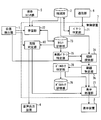
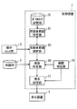
- FIG. 1 is a block diagram illustrating an example of a schematic configuration of the driving support system 100.
- FIG. 2 is a block diagram illustrating an example of a schematic configuration of the control device 7 according to the first embodiment.
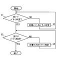
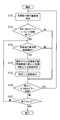
- FIG. 3 is a flowchart showing an example of the flow of the map network patterning process in the pattern determining unit 71 of the control device 7,
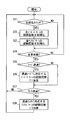
- FIG. 4 is a flowchart illustrating an example of the flow of the experience number learning process in the learning unit 72 of the control device 7.
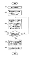
- FIG. 5 is a flowchart showing an example of the flow of possible action range display processing in the control device 7.
- FIG. 1 is a block diagram illustrating an example of a schematic configuration of the driving support system 100.
- FIG. 2 is a block diagram illustrating an example of a schematic configuration of the control device 7 according to the first embodiment.
- FIG. 3 is a flowchart showing an example of the flow of the map network patterning process in the pattern determining unit 71 of the control device 7
- FIG. 4 is a
- FIG. 6 is a diagram illustrating an example of a display of a possible action range.
- FIG. 7 is a flowchart showing an example of the flow of overcoming notification processing in the control device 7
- FIG. 8 is a block diagram for explaining a schematic configuration of the control device 7 in Modification 4.
- FIG. 9 is a flowchart showing an example of the flow of the ranking display process in the control device 7
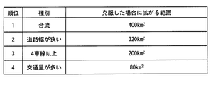
- FIG. 10 is a diagram illustrating an example of a display result of ranking according to the size of the actionable range that expands when the bottleneck pattern is overcome
- FIG. 11 is a diagram illustrating an example of a display of the possible range of action after overcoming
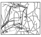
- FIG. 12 is a diagram for explaining an example of an aspect in which the actionable range after overcoming and the actionable range before overcoming the bottleneck pattern are displayed in a comparable manner;
- FIG. 13 is a block diagram for explaining a schematic configuration of the control device 7 in Modification 7.
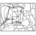
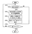
- FIG. 14 is a flowchart showing an example of the flow of overcoming goal display processing in the control device 7.
- FIG. 15 is a block diagram for explaining a schematic configuration of the control device 7 in Modification 8.
- FIG. 16 is a flowchart illustrating an example of the flow of overcoming arrival facility display processing in the control device 7.
- FIG. 1 is a diagram illustrating an example of a schematic configuration of a driving support system 100 to which the present disclosure is applied.
- the driving support system 100 is used in a vehicle.
- the position detector 1, the map DB 2, the display device 3, the voice output device 4, the operation switch group 5, the communication unit 6, and the control device 7 are used. Is included.
- a vehicle using the driving support system 100 is referred to as a host vehicle.
- the position detector 1 sequentially detects the position of the vehicle using, for example, a positioning system that detects the current position of the vehicle (hereinafter, the vehicle position) based on radio waves from the positioning satellite.
- the vehicle position is represented by latitude / longitude coordinates, for example.
- the map DB 2 stores road map data, POI (Points Of Interest) data of various facilities, and the like.
- the road map data includes road data including node data and link data.
- the POI data is data indicating the name, address, position, and attribute of the facility corresponding to the POI.
- the link data includes a unique number (link ID) identifying the link, a link length indicating the link length, link shape information, a segment length indicating the segment length, and link start and end node coordinates (latitude / longitude). , Road name, road type, road width, number of lanes, presence / absence of right / left turn dedicated lane, number of dedicated lanes, one-way traffic regulation, speed regulation value, etc.
- the node data is data such as a node ID given a unique number for each node on the map, node coordinates, node name, a connection link ID describing a link ID of a link connected to the node, and an intersection type. Consists of
- Facility location data is, for example, coordinates expressed in latitude / longitude.
- the facility attribute data is data representing the type and nature of the facility. Examples of facility types include stores such as restaurants and entertainment facilities such as theme parks. Further, as an example of the property of the facility, there is a ranking in which the number of users, evaluation, and the like are ranked.
- the data of the map DB 2 may be acquired by the control device 7 being downloaded from the center through the communication unit 6 to be described later, or may be stored in advance.
- the display device 3 displays text and images in accordance with instructions from the control device 7.
- the display device 3 is capable of full-color display and can be configured using a liquid crystal display or the like.
- the display device 3 may be configured to use a display provided on an instrument panel or the like, or may be configured to use HUD (Head-Up Dispray).
- the audio output device 4 is composed of a speaker or the like, and outputs audio according to instructions from the control device 7.
- the operation switch group 5 for example, a touch switch or a mechanical switch integrated with the display device 3 is used, and an operation instruction for various functions is given to the control device 7 by a switch operation.
- the communication unit 6 communicates with the center via, for example, a roadside device, a base station, or a network.
- a vehicle-mounted communication module used for telematics communication such as DCM (data communication module), or a small vehicle-mounted communication device that receives traffic information transmitted from a radio beacon or an optical beacon installed on the road Etc. can be used.
- the control device 7 is mainly configured as a microcomputer, and each includes a known CPU, a memory such as a ROM and a RAM, an I / O, and a bus connecting them.
- the control device 7 executes various processes based on various information input from the position detector 1, the map DB 2, the operation switch group 5, and the communication unit 6.
- the control device 7 corresponds to the driving support device in the claims.
- control device 7 may be configured in hardware by one or a plurality of ICs.
- the control device 7 includes a pattern determination unit 71, a learning unit 72, a count storage unit 73, a route search unit 74, an immature pattern specification unit 75, a range specification unit 76, a display processing unit 77, and a bottleneck specification.
- Unit 78, bottleneck storage unit 79, and overcoming determination unit 80 Processing in each part of the control device 7 will be described in detail later.
- the map network patterning process is a process related to pattern determination for determining which pattern of a plurality of types of classified patterns corresponds to all links and all nodes included in the map DB 2.
- the flowchart of FIG. 3 is started when the driving support system 100 is used for the first time or when the road map data in the map DB 2 is updated.
- patterning is performed based on information that the driver must consider when a vehicle passes through a node (that is, an intersection) or a link (that is, a road). For example, for node patterns, intersection shapes such as “T-junction”, “crossroads”, “more than five forks”, “merge”, signal rules such as “no right turn signal”, “no pedestrian separation signal”, etc. There are patterns categorized by. Link patterns are classified according to road conditions such as “High speed regulation value”, “Narrow road width”, “More than 4 lanes”, “High traffic volume”, “Large traffic”, etc. There is a pattern made.
- the traffic information received by the communication unit 6 may be used.
- a map network that is, a road network
- pattern determination is performed for all nodes and all links.
- step S1 when the pattern determination for all nodes in the map DB 2 is not completed (NO in S1), the process proceeds to step S2. On the other hand, when the pattern determination for all nodes is completed (YES in S1), the process proceeds to step S3. Since the pattern determination is not performed immediately after the flowchart of FIG. 3 is started, the process proceeds to S2.
- step S2 pattern determination is performed for a node whose pattern determination is not completed among nodes whose data is stored in the map DB2. And as a result of performing pattern determination, when corresponding to the classified node pattern, the node pattern is associated with the node and stored in, for example, the map DB 2.
- the pattern determination unit 71 associates the node pattern “join” with the node and stores it in the map DB 2.
- the plurality of types of node patterns may be stored in association with the nodes.
- step S3 when the pattern determination for all the links in the map DB 2 by the pattern determination unit 71 is not completed (NO in S3), the process proceeds to step S4. On the other hand, when the pattern determination for all links is completed (YES in S3), the map network patterning process is terminated.
- step S4 pattern determination is performed for links for which pattern determination has not ended among links whose data is stored in the map DB2. And when it corresponds to the classified link pattern as a result of pattern determination, the link pattern is matched with the link and memorize
- the pattern determination unit 71 associates the link pattern “the road width is narrow” with the link and stores it in the map DB 2.
- the plurality of types of link patterns may be stored in association with the link.
- the control device 7 determines which pattern of a plurality of types of classified patterns corresponds to all links and all nodes included in the map DB 2, and associates the determined pattern with the link or node.
- stored in map DB2 was shown, it does not necessarily restrict to this.
- data in which corresponding patterns are previously associated with links and nodes may be stored in the map DB 2 in advance, and this data may be stored in the communication unit 6 by the control device 7. It is good also as a structure etc. which are downloaded and memorize
- the experience count learning process is a process of counting the experience count indicating how much the driver has experienced each node pattern and each link pattern.
- the number of experiences counted for each node pattern and each link pattern is stored in the count storage unit 73 for each node pattern and each link pattern. For example, the node pattern “join” is stored in association with the number of experiences “1”, the node pattern “cross road” is associated with the number of experiences “8”, and the like.
- step S21 if it is the initialization timing (YES in S21), the process proceeds to step S22. On the other hand, if it is not the initialization timing (NO in S21), the process proceeds to step S24.
- the initialization timing include when the driving support system 100 is used for the first time or when the driver makes an initialization request via the operation switch group 5.
- step S22 the number of experiences of all node patterns in the count storage unit 73 is initialized. That is, the experience count for all node patterns is set to zero.
- step S23 the number of experiences of all link patterns in the count storage unit 73 is initialized. That is, the experience count for all link patterns is zero.
- step S24 for example, it is determined whether or not the own vehicle is moving depending on whether or not the own vehicle position sequentially detected by the position detector 1 is varied. And when it determines with the own vehicle moving (it is YES at S24), it moves to S25. On the other hand, when it determines with the own vehicle not moving (it is NO at S24), it returns to S21 and repeats a process.
- step S25 it is determined from the node data stored in the map DB 2 and the vehicle position sequentially detected by the position detector 1 whether or not the vehicle has passed the node. As an example, it is determined that the own vehicle has passed the node when the position of the own vehicle that is sequentially detected exceeds the node. And when it determines with the own vehicle having passed the node (it is YES at S25), it moves to S26. On the other hand, if it is not determined that the vehicle has passed the node (NO in S25), the process proceeds to step S27.
- step S26 1 is added to the number of experiences stored in the count storage unit 73 for the node pattern associated in the map DB 2 with the node determined to have passed in S25. For example, if the node pattern “cross road” is associated with the passing node, the experience count for the node pattern “cross road” stored in the count storage unit 73 is incremented by 1, and the process proceeds to step S27. In addition, what is necessary is just to set it as the structure which transfers to step S27, without adding the frequency
- step S27 it is determined whether or not the vehicle has passed the link from the link data stored in the map DB 2 and the vehicle position sequentially detected by the position detector 1. As an example, when the vehicle position that is sequentially detected exceeds the end node coordinates of the link, it is determined that the vehicle has passed the link. And when it determines with the own vehicle having passed the link (it is YES at S27), it moves to step S28. On the other hand, when it is not determined that the vehicle has passed the link (NO in S27), the process returns to S21 and the process is repeated.
- step S28 1 is added to the number of experiences stored in the count storage unit 73 for the link pattern associated in the map DB2 with the link determined to have passed in S27, and the process is repeated by returning to S21. For example, if the link pattern “narrow road width” is associated with the passing link, the number of experiences for the link pattern “narrow road width” stored in the count storage unit 73 is incremented by one.
- the link pattern matched in map DB2 does not exist in the link determined to have passed in S27, it should just be set as the structure which returns to S21 and repeats a process, without adding the frequency
- the actionable range display process is a process of displaying an actionable range in consideration of the driver's link pattern and node pattern traffic experience.
- the flowchart of FIG. 5 may be configured to start when the driver requests display of the actionable range via the operation switch group 5.
- step S41 the route search unit 74 acquires the starting point position.
- the own vehicle position detected by the position detector 1 may be acquired as the starting position, or the driver's home position may be acquired as the starting position if the driver's home position can be acquired.
- the immature pattern specifying unit 75 specifies a node pattern and a link pattern whose number of experiences is less than a predetermined number based on the storage of the count storage unit 73.
- the predetermined number is a value that can be arbitrarily set, and may be set to one time, for example, or may be set to a plurality of times more than once by adjusting the driving experience years, driving experience distance, and the like. Alternatively, the driver may set the number of times via the operation switch group 5.
- step S43 the route search unit 74 prohibits passage of nodes and links corresponding to node patterns (hereinafter referred to as immature node patterns) and link patterns (hereinafter referred to as immature link patterns) identified as less than the predetermined number of times in S42.
- the route search is performed in all directions from the starting position acquired in S41.
- the immature node pattern and the immature link pattern correspond to the immature pattern in the claims.
- a route to a search end point that can be reached according to traffic restrictions such as one-way traffic without passing through the same link more than once is searched.
- the search end point includes a node corresponding to the immature node pattern, a link start node corresponding to the immature link pattern, a link end node corresponding to the dead end, and the like.
- the search is sequentially performed for branches in the middle of the route in all directions that can proceed from the starting position.
- step S44 when the route search is completed in all directions (YES in S44), the process proceeds to step S45. On the other hand, if the route search has not ended (NO in S44), the process returns to S43, and the process is repeated for the route for which the route search has not ended.
- the range specifying unit 76 specifies a range surrounded by connecting search end points of a plurality of routes obtained as a result of the route search in all directions by the route search unit 74 as an actionable range.
- the range specifying unit 76 corresponds to the actionable range specifying unit in the claims.
- the bottleneck specifying unit 78 is an bottleneck that narrows the actionable range of the immature node pattern and the immature link pattern corresponding to the search end point used for specifying the actionable range in the range specifying unit 76. Specify as a pattern. That is, the immature node pattern or the immature link pattern that causes the limitation to the actionable range specified by the range specifying unit 76 is specified as the bottleneck pattern. Then, the bottleneck specifying unit 78 stores the specified bottleneck pattern in the bottleneck storage unit 79. As an example, a list of immature node patterns and immature link patterns specified as bottleneck patterns may be stored in the bottleneck storage unit 79. The bottleneck pattern corresponds to the failure pattern in the claims.
- step S46 the display processing unit 77 displays a display in which the actionable range specified in S45 is superimposed on the map based on the data stored in the map DB 2 and the actionable range specified in S45.
- the following description will be given by taking as an example a case where the starting position acquired in S41 and the bottleneck pattern specified by the bottleneck specifying unit 78 are displayed superimposed on the map.
- FIG. 6 the case where the bottleneck pattern is the node pattern “merge” and the link pattern “the road width is narrow” will be described as an example.
- A is the starting position
- the range surrounded by the dotted line B is the actionable range
- P1 is an icon representing the bottleneck pattern “join”
- P2 is an icon representing the bottleneck pattern “narrow road width” Yes.
- the actionable range and the starting position are displayed superimposed on the map.
- an icon representing the type of the bottleneck pattern is displayed at the position of the bottleneck pattern corresponding to the boundary point of the actionable range.
- the overcoming notification process is a process for determining whether the driver has overcome the immature node pattern or the immature link pattern, and performing notification indicating that the driver has overcome when it is determined that the driver has overcome.
- the flowchart of FIG. 7 may be configured to start when the power of the control device 7 is turned on, such as when the ignition power of the host vehicle is turned on.
- step S61 similarly to S24, the overcoming determination unit 80 determines whether or not the host vehicle is moving. And when it determines with the own vehicle moving (it is YES at S61), it moves to step S62. On the other hand, when it determines with the own vehicle not moving (it is NO at S61), it moves to step S65.
- step S62 from the number of experiences for each node pattern and link pattern stored in the count storage unit 73, the node data stored in the map DB 2, and the vehicle position sequentially detected by the position detector 1, The overcoming determination unit 80 determines whether or not the vehicle has passed a node corresponding to the immature node pattern or a link corresponding to the immature link pattern (hereinafter, immature pattern).
- the number of node patterns or node links associated with the node or link is less than the predetermined number of times described above. In this case, it is determined that the vehicle has passed the immature pattern. And when it determines with the own vehicle having passed the immature pattern (it is YES at S62), it moves to S63. On the other hand, when it is not determined that the vehicle has passed the immature pattern (NO in S62), the process proceeds to step S65.
- step S63 the overcoming determination unit 80 determines whether or not the number of experiences of the node pattern and the link pattern corresponding to the immature pattern has reached the predetermined number of times because the vehicle has passed the immature pattern. If it is determined that the predetermined number of times has been reached (YES in S63), the process proceeds to step S64. On the other hand, when it is determined that the predetermined number of times has not been reached (NO in S63), the process proceeds to step S65.
- step S64 the overcoming determination unit 80 instructs the audio output device 4 to perform audio output indicating that the immature pattern has been overcome, or the display processing unit 77 displays on the display device that the immature pattern has been overcome. Or informing the driver that the immature pattern has been overcome.
- step S65 when it is the end timing of the overcoming notification process (YES in S65), the overcoming notification process is ended. If it is not the end timing of the overcoming notification process (NO in S65), the process returns to S61 and is repeated.
- the end timing of the overcoming notification process there is a time when the power source of the control device 7 is turned off because the ignition power source of the host vehicle is turned off.
- the driver can superimpose on the map the actionable range in which the driver can travel without passing the immature pattern with less than a predetermined number of experiences. It is possible to know an actionable range in which the user can travel without passing through points with insufficient experience even if he / she freely selects and travels.
- the driver can freely select the road network and travel while having a sense of security that it is not necessary to pass points with insufficient experience within this possible range of action.
- it is possible to reduce the psychological load that the driver passes through points that are inexperienced, while making it easy to obtain the pleasure of traveling by freely selecting the road network.
- the display of the icon indicating the type of the bottleneck pattern that is an obstacle to narrow the actionable range that is, the bottleneck pattern that is an immature pattern that causes the actionable range to be narrowed
- the driver can know which bottleneck pattern to overcome to expand the actionable range.
- the driver by making the driver recognize which bottleneck pattern should be overcome to expand the range of action, it is possible to derive motivation to overcome the bottleneck pattern and reduce the psychological load that passes through the bottleneck pattern. It becomes possible.
- the bottleneck pattern is displayed together with the actionable range at the position of the bottleneck pattern on the map, even if the driver goes to the bottleneck pattern The driver can know in advance whether he / she is heading toward a bottleneck pattern, and the psychological load that passes through the bottleneck pattern can be reduced.
- the driver when the immature pattern is overcome, the driver is informed that the immature pattern has been overcome, so the driver can challenge to overcome the immature pattern while enjoying it like a game, and the psychology that passes through the points with insufficient experience It becomes possible to reduce the load.
- the driving support system 100 can be used in a vehicle, so that points of patterns that the user has never experienced can be grasped in advance. Thus, it is possible to reduce the psychological load that passes through the bottleneck pattern overseas.
- Modification 1 In the above-described embodiment, the configuration in which the display indicating the bottleneck pattern is performed by superimposing the icon indicating the type of the bottleneck pattern on the map and performing the display is shown, but the present invention is not necessarily limited thereto. For example, it is good also as a structure (henceforth modification 1) which displays the bottleneck pattern by displaying the list etc. which showed the kind of bottleneck pattern.
- the driver can know which bottleneck pattern should be overcome to expand the possible range of action. Therefore, the driver draws motivation to overcome the bottleneck pattern from the driver, and the bottleneck pattern It becomes possible to reduce the psychological load of the driver who passes the vehicle.
- the configuration in which it is determined that the immature pattern is overcome when the number of experiences of the immature pattern reaches a predetermined number of times or more is not necessarily limited thereto.
- it may be configured to determine that the immature pattern has been overcome when the difference between the behavior of the vehicle at the time of passing the immature pattern and the model behavior is a predetermined value or less (hereinafter, modified example 2). .
- the behavior of the host vehicle may be specified from the time change of the value detected by a sensor that detects the motion of the host vehicle such as a vehicle speed sensor, an acceleration sensor, or a rudder angle sensor.
- a sensor that detects the motion of the host vehicle such as a vehicle speed sensor, an acceleration sensor, or a rudder angle sensor.
- a value specified by simulation or experiment in advance for each node pattern and node link may be stored in advance in the memory or the like of the control device 7.
- Modification 3 it is determined whether or not the immature pattern has been overcome, and when it is determined that the pattern has been overcome, a notification that indicates that the pattern has been overcome is shown. For example, it is determined whether the bottleneck pattern of the immature patterns has been overcome, and when it is determined that the bottleneck pattern has been overcome, a notification that indicates that the bottleneck pattern has been overcome and that the actionable range has been expanded (hereinafter, modified example 3) is performed. ).
- the above-described overcoming notification process may be configured to perform processing only on the bottleneck patterns stored in the bottleneck storage unit 29 among the immature patterns. If it is determined that the bottleneck pattern has been overcome, the overcome bottleneck pattern may be excluded from the bottleneck storage unit 79.
- the immature pattern for notifying overcoming is limited to the bottleneck pattern among the immature patterns.
- the bottleneck pattern is an immature pattern that hinders the actionable range among the immature patterns. Therefore, when the bottleneck pattern is overcome, the actionable range is surely expanded.
- the driver when the actionable range is expanded, the driver is notified that the overcome bottleneck pattern and the actionable range are expanded, so that the driver can more effectively overcome the immature pattern. You will be able to overcome the immature pattern while feeling it. As a result, the driver's motivation for overcoming the immature pattern can be further increased.
- the bottleneck pattern may be ranked according to the size of the actionable range that expands if the bottleneck pattern is overcome, and the ranking result may be presented to the driver (hereinafter, modified example 4).
- Modification 4 will be described.
- the driving support system 100 according to the modified example 4 is the driving according to the first embodiment except that the control device 7 further includes a post-overcoming range specifying unit 81 and a ranking unit 82 and the processing in the control device 7 is partially different. The same as the support system 100.
- the control device 7 in Modification 4 includes a pattern determination unit 71, a learning unit 72, a count storage unit 73, a route search unit 74, an immature pattern specification unit 75, a range specification unit 76, a display processing unit 77, a bottleneck specification unit 78, A bottleneck storage unit 79, an overcoming determination unit 80, a post-overcoming range specifying unit 81, and a ranking unit 82 are provided.
- the post-overcoming range specifying unit 81 specifies an actionable range that expands when the bottleneck pattern is temporarily overcome (hereinafter referred to as an actionable range after overcoming).
- the ranking unit 82 ranks the bottleneck pattern according to the size of the actionable range that expands when the bottleneck pattern is overcome.
- the ranking display process is a process of ranking the bottleneck pattern according to the size of the actionable range that expands when the bottleneck pattern is overcome and displaying the ranking result.
- the flow chart of FIG. 9 may be configured to start when, for example, the driver makes a bottleneck pattern ranking display request via the operation switch group 5.
- the action specifying range is already specified by the range specifying unit 76
- the bottleneck pattern is already specified by the bottleneck specifying unit 78
- the specified bottleneck pattern is stored in the bottleneck storage unit 79. The description will be made assuming that
- the post-overcoming range specifying unit 81 selects one type of bottleneck pattern from the bottleneck patterns stored in the bottleneck storage unit 79.
- the configuration may be such that the bottleneck patterns are selected in the order of the list.
- step S82 the bottleneck pattern selected in S81 is temporarily allowed to pass, while the remaining bottleneck patterns are not allowed to pass, and further route search is performed from the search end point when the action specifying range is specified by the range specifying unit 76. I do. For example, when the search end point corresponds to the bottleneck pattern selected in S81, the search end point is allowed to pass, and the route search is performed beyond the search end point. On the other hand, if the search end point does not correspond to the bottleneck pattern selected in S81, the search end point remains impassable, and the route search ends at the search end point.
- step S83 the bottleneck pattern selected in S81 is a range surrounded by connecting the search end points of the plurality of routes obtained as a result of the route search in S82 in the same manner as in S45. It is specified as the possible range of action after overcoming the problem. Therefore, the post-overcoming range specifying unit 81 corresponds to the post-overcoming specifying unit.
- step S84 when the identification of the actionable range after overcoming all the bottleneck patterns stored in the bottleneck storage unit 79 is completed (YES in S84), the process proceeds to step S85. On the other hand, if at least one type of bottleneck pattern stored in the bottleneck storage unit 79 has not yet been identified (NO in S84), the process returns to S81 to return to the actionable range after overcoming. The process is repeated for the bottleneck pattern for which the identification of is not completed.
- the ranking unit 82 uses the range specifying unit 76 for all bottleneck patterns stored in the bottleneck storage unit 79 based on the post-overcoming action possible range specified by the post-overcoming range specifying unit 81. Ranking is performed according to the size of the range expanded from the identified actionable range. Therefore, the ranking unit 82 corresponds to the rank specifying unit of the claims. As an example, it may be configured such that the higher the extension distance of the map network is, the higher the ranking is, and the higher the ranking is as the area of the post-overcoming action possible range specified by the post-overcoming range specifying unit 81 increases. It is good also as a structure.
- step S86 the display device 3 is caused to display the result of ranking performed by the ranking unit 82.
- the display result of the ranking result may be an aspect in which the ranking of the size of the actionable range that expands when overcoming is recognized for each bottleneck pattern.
- FIG. 10 a list display in which the types of bottleneck patterns and the area of the actionable range that expands when overcome is performed in the order of the size of the actionable range that expands when overcome is performed. It is sufficient to adopt a configuration that allows
- the driver can know the order of the range of the actionable range that is expanded when the bottleneck pattern is overcome for each bottleneck pattern, so the actionable range can be efficiently expanded.
- the driver can recognize the bottleneck pattern that must be overcome with priority. As a result, it is possible for the driver to efficiently expand the possible range of action.
- Modification 5 Moreover, it is good also as a structure (modification 5) which displays the actionable range which expands when a bottleneck pattern is overcome according to a bottleneck pattern.
- the display processing unit 77 displays the post-overcoming action possible range specified by the post-overcoming range specifying unit 81 on the display device 3 by superimposing on the map for each bottleneck pattern. What is necessary is just to make it the structure to make.
- the display processing unit 77 performs an action after overcoming the selected bottleneck pattern. What is necessary is just to set it as the structure etc. which are displayed on the display apparatus 3 by superimposing a possible range on a map.
- FIG. 11 shows an example of a display of the possible action range after overcoming.
- the possible range is shown.
- a in FIG. 11 indicates the above-described starting position
- the dotted line C indicates the possible range of action after overcoming
- P1 indicates an icon indicating the bottleneck pattern “join”.
- the driver since the range of action that can be expanded when the bottleneck pattern is overcome is displayed superimposed on the map, the driver can determine how much the range of action that can be expanded when the bottleneck pattern is overcome. Can be intuitively recognized.
- Modification 6 Moreover, when displaying the overcoming action possible range that expands when the bottleneck pattern is overcome as in the modified example 5 and displaying it in a superimposed manner on the map, the configuration is displayed so that it can be compared with the actionable range before overcoming the bottleneck pattern. (Hereinafter, Modification 6) may be adopted.
- the actionable range before overcoming the bottleneck pattern may be configured to use the actionable range specified by the range specifying unit 76.
- a line type indicating the actionable range after overcoming As an example of an aspect in which the actionable range after overcoming and the actionable range before overcoming the bottleneck pattern are displayed in a comparable manner, as shown in FIG. 12, a line type indicating the actionable range after overcoming (see FIG. 12).
- a line type (B in FIG. 12) indicating a possible range of action before overcoming the bottleneck pattern is made different and displayed on the map at the same time.
- Modification 7 Moreover, it is good also as a structure (henceforth the modification 7) which shows a driver the bottleneck pattern which needs to be overcome in order to reach the destination which a driver wants to visit.
- Modification 7 will be described.
- the driving support system 100 of the modified example 7 is the same as that of the first embodiment except that the control device 7 further includes a destination setting unit 83 and a bottleneck extraction unit 84, and the processing in the control device 7 is partially different. This is the same as the driving support system 100.
- control device 7 in the modified example 7 will be described with reference to FIG. In FIG. 13, for the sake of convenience, only functional blocks necessary for the description of the modified example 7 are shown among the functional blocks provided in the control device 7.
- the control device 7 in Modification 7 includes a pattern determination unit 71, a learning unit 72, a count storage unit 73, a route search unit 74, an immature pattern specifying unit 75, a range specifying unit 76, a display processing unit 77, a bottleneck specifying unit 78, A bottleneck storage unit 79, an overcoming determination unit 80, a destination setting unit 83, and a bottleneck extraction unit 84 are provided.
- the destination setting unit 83 sets a location input from the driver via the operation switch group 5 as a destination.
- the bottleneck extraction unit 84 will be described in detail later.
- the overcoming target display process in the control device 7 will be described with reference to the flowchart of FIG.
- the overcoming target display process is a process of displaying a bottleneck pattern that needs to be overcome in order to reach the destination.
- the flowchart in FIG. 14 may be configured to start when the control device 7 is turned on, for example, by turning on the ignition power of the host vehicle.
- the description will be made on the assumption that the bottleneck pattern specified by the bottleneck specifying unit 78 is stored in the bottleneck storage unit 79.
- step S101 when the destination setting unit 83 sets the destination (YES in S101), the process proceeds to step S102. On the other hand, when the destination setting unit 83 has not set the destination (NO in S101), the process proceeds to step S105.
- step S102 the route searching unit 74 searches for a recommended route from the above-described starting position to the destination set by the destination setting unit 83.
- a recommended route search an optimum route satisfying preset search conditions such as distance priority and time priority is searched from the origin position, the destination, and the data of the map DB 2 according to a known route search method. .
- the bottleneck extraction unit 84 refers to the bottleneck pattern stored in the bottleneck storage unit 79, and the node pattern associated with the node and the link in the recommended route searched in S102 in the map DB2. Among the link patterns, the pattern corresponding to the bottleneck pattern is extracted. Therefore, the bottleneck extraction unit 84 corresponds to the overcoming target specifying unit in the claims.
- step S104 the display processing unit 77 causes the display device 3 to display the bottleneck pattern extracted in S103.
- the bottleneck pattern extracted in S103 corresponds to the overcoming target pattern in the claims.
- the configuration may be such that the bottleneck pattern is displayed in a list in the order of appearance when the recommended route is advanced from the starting position to the destination, or the bottleneck pattern on the recommended route shown on the map It is good also as a structure which displays the icon which shows the classification of a bottleneck pattern in the position.
- the extracted bottleneck pattern types may be simply displayed as a list.
- step S105 when it is the end timing of the overcoming target display process (YES in S105), the overcoming target display process is ended. If it is not the end timing of the overcoming goal display process (NO in S105), the process returns to S101 and the process is repeated.
- the end timing of the overcoming target display process there is a time when the power source of the control device 7 is turned off because the ignition power source of the host vehicle is turned off.
- Modification 8 Moreover, it is good also as a structure (henceforth the modification 8) which shows the information of the plant
- the driving support system 100 according to the modified example 8 further includes a post-overcoming range specifying unit 81, a post-overcoming range selecting unit 85, and a facility specifying unit 86 in the control device 7, and the processing in the control device 7 is partially different. Is the same as the driving support system 100 of the first embodiment.
- the control device 7 in Modification 8 includes a pattern determination unit 71, a learning unit 72, a count storage unit 73, a route search unit 74, an immature pattern specification unit 75, a range specification unit 76, a display processing unit 77, a bottleneck specification unit 78, A bottleneck storage unit 79, an overcoming determination unit 80, a post-overcoming range specifying unit 81, a post-overcoming range selecting unit 85, and a facility specifying unit 86 are provided.
- the post-overcoming range specifying unit 81 is the same as that described in the fourth modification.
- the post-overcoming range selection unit 85 selects the post-overcoming action possible range for the bottleneck pattern requested from the driver via the operation switch group 5 from the post-overcoming action possible range specified by the post-overcoming range specifying unit 81. select.
- the facility specifying unit 86 specifies a facility that can be newly reached when the actionable range specified by the range specifying unit 76 extends to the post-overcoming actionable range selected by the post-overcoming range selection unit 85.
- the overcoming arrival facility display process is a process of displaying information on a facility that can be newly reached by the driver when the bottleneck pattern is temporarily overcome.
- the 16 may be configured to start when the control device 7 is turned on, for example, when the ignition power of the host vehicle is turned on.
- the description will be made on the assumption that the bottleneck pattern specified by the bottleneck specifying unit 78 is stored in the bottleneck storage unit 79.
- step S121 the post-overcoming range specifying unit 81 specifies the post-overcoming action possible range in the same manner as described in the fourth modification.
- step S122 when the identification of the range of possible action after overcoming has been completed for all the bottleneck patterns stored in the bottleneck storage unit 79 (YES in S122), the process proceeds to step S123. On the other hand, if at least one type of bottleneck pattern stored in the bottleneck storage unit 79 has not been identified (see NO in S122), the process proceeds to S125.
- step S123 when the post-overcoming range selection unit 85 selects the post-overcoming action possible range (YES in S123), the process proceeds to step S124. On the other hand, if the post-overcoming range selection unit 85 does not select the post-overcoming action possible range (NO in S123), the process proceeds to step S125.
- step S124 the facility that can be newly reached by the facility specifying unit 86 when the actionable range specified by the range specifying unit 76 extends to the post-overcoming actionable range selected by the post-overcoming range selection unit 85. Is identified.
- the facility located in a range obtained by subtracting the actionable range specified by the range specifying unit 76 from the actionable range after overcoming selected by the range selecting unit 85 after overcoming may be configured to identify several facilities that rank higher in the ranking of the number of users, evaluation, and the like. In addition, it is good also as a structure etc. which identify the facility with the same classification as the facility which a driver uses frequently. It can be said that a facility with the same type as a facility that ranks higher in the number of users, evaluations, etc. or that is often used by the driver is a recommended facility that is estimated to attract the driver's interest.
- step S125 the display processing unit 77 causes the display device 3 to display the information on the facility specified in S124.
- the facility information may be displayed in such a manner that a facility name or an icon indicating the facility is displayed at the location of the facility on the map, or text describing the content of the facility is displayed.
- step S126 when the types of bottleneck patterns stored in the bottleneck storage unit 79 are reduced and the bottleneck patterns are newly overcome (YES in S126), the process returns to S121 and is repeated. On the other hand, when the bottleneck pattern is not newly overcome (NO in S126), the process proceeds to step S127.
- step S127 when it is the end timing of the overcoming arrival facility display processing (YES in S127), the overcoming arrival facility display processing is ended. If it is not the end timing of the overcoming arrival facility display process (NO in S127), the process returns to S121 and is repeated.
- An example of the end timing of the overcoming arrival facility display process is when the power supply of the control device 7 is turned off because the ignition power of the host vehicle is turned off.
- Modification 9 The various processes described above may be performed for each driver.
- the experience count learning process for each driver is performed to store the node pattern and node link experience count for each driver
- the immature pattern for each driver is specified to display the possible action range for each driver, What is necessary is just to set it as the structure which memorize
- the individual driver may be configured to use, for example, a weight scale or a pressure sensor provided in the seating portion of the driver's seat and specify the weight measured by the weight scale and the detected value by the pressure sensor.
- the configuration may be such that an individual driver is specified from the ID received from the electronic key.
- a mobile terminal such as a multi-function mobile phone having a GPS function may be used.
- each section is expressed as, for example, S1. Further, each section can be divided into a plurality of subsections, while a plurality of sections can be combined into one section. Further, each section configured in this manner can be referred to as a device, module, or means.
Landscapes
- Engineering & Computer Science (AREA)
- Radar, Positioning & Navigation (AREA)
- Remote Sensing (AREA)
- Physics & Mathematics (AREA)
- General Physics & Mathematics (AREA)
- Automation & Control Theory (AREA)
- Chemical & Material Sciences (AREA)
- Combustion & Propulsion (AREA)
- Transportation (AREA)
- Mechanical Engineering (AREA)
- Mathematical Physics (AREA)
- Theoretical Computer Science (AREA)
- Business, Economics & Management (AREA)
- Educational Administration (AREA)
- Educational Technology (AREA)
- Health & Medical Sciences (AREA)
- General Health & Medical Sciences (AREA)
- Social Psychology (AREA)
- Navigation (AREA)
- Instructional Devices (AREA)
- Traffic Control Systems (AREA)
Abstract
車両で用いられる運転支援装置は、表示装置に地図の表示を行わせる表示処理部(77)と、前記地図に含まれる道路網の構成要素を所定の種別にパターン分けしたパターンのうちから、前記車両のドライバが経験不足な未熟パターンを特定する未熟パターン特定部(75)と、設定された起点から前記未熟パターン特定部で特定した未熟パターンを通過せずに前記車両が到達できる行動可能範囲を特定する行動可能範囲特定部(76)とを備える。前記表示処理部は、前記行動可能範囲特定部で特定した行動可能範囲を前記地図に重畳した表示を表示装置に行わせる。
Description
本出願は、2014年6月4日に出願された日本出願番号2014-115955号に基づくもので、ここにその記載内容を援用する。
本開示は、ドライバに情報を提供することによってドライバの運転を支援する運転支援装置に関するものである。
自動車での移動には、全国につながる道路網を自由に選択して走行できる楽しさがある。一方で、ドライバの運転経験によっては、対向車とのすれ違いが困難なポイント、車線変更や合流が困難なポイントなどの難所となるポイントが存在することで、心理的な負荷により行動範囲が制限されてしまう場合がある。
そこで、この問題を解決する手段として、特許文献1には、運転操作が困難と想定される難所を予め登録し、現在位置から目的地までの経路計算においてこの登録された難所を通過しない経路を計算して案内する技術が開示されている。
しかしながら、特許文献1に開示の技術では、難所を避けた経路を案内することで、その難所について経験不足なドライバがその難所を通過する心理的な負荷を軽減することができるものの、案内された経路を外れる場合には難所とするポイントにいつ遭遇するかわからないため、道路網を自由に選択して走行できる楽しさが得られにくいという問題点がある。
本開示は、道路網を自由に選択して走行できる楽しさを得られやすくしながらも、ドライバが経験不足なポイントを通過する心理的な負荷を軽減することを可能にする運転支援装置を提供することを目的とする。
本開示の第一の態様において、車両で用いられる運転支援装置は、表示装置に地図の表示を行わせる表示処理部と、前記地図に含まれる道路網の構成要素を所定の種別にパターン分けしたパターンのうちから、前記車両のドライバが経験不足な未熟パターンを特定する未熟パターン特定部と、設定された起点から前記未熟パターン特定部で特定した未熟パターンを通過せずに前記車両が到達できる行動可能範囲を特定する行動可能範囲特定部とを備える。前記表示処理部は、前記行動可能範囲特定部で特定した行動可能範囲を前記地図に重畳した表示を表示装置に行わせる。
上記の運転支援装置によれば、車両のドライバが経験不足な道路網の構成要素を通過せずに車両が到達できる行動可能範囲を地図に重畳してドライバに提示するので、ドライバは、道路網を自由に選択して走行したとしても経験不足なポイントを通過せずに走行することができる行動可能範囲を知ることができる。よって、ドライバは、この行動可能範囲内で、経験不足なポイントを通過せずに済むという安心感を持ちながら、道路網を自由に選択して走行することが可能になる。その結果、道路網を自由に選択して走行できる楽しさを得られやすくしながらも、ドライバが経験不足なポイントを通過する心理的な負荷を軽減することが可能になる。
本開示についての上記目的およびその他の目的、特徴や利点は、添付の図面を参照しながら下記の詳細な記述により、より明確になる。その図面は、
図1は、運転支援システム100の概略的な構成の一例を示すブロック図であり、
図2は、実施形態1における制御装置7の概略的な構成の一例を示すブロック図であり、
図3は、制御装置7のパターン判定部71での地図ネットワークパターン化処理の流れの一例について示すフローチャートであり、
図4は、制御装置7の学習部72での経験回数学習処理の流れの一例について示すフローチャートであり、
図5は、制御装置7での行動可能範囲表示処理の流れの一例について示すフローチャートであり、
図6は、行動可能範囲の表示の一例を示す図であり、
図7は、制御装置7での克服報知処理の流れの一例について示すフローチャートであり、
図8は、変形例4における制御装置7の概略的な構成について説明するためのブロック図であり、
図9は、制御装置7でのランキング表示処理の流れの一例について示すフローチャートであり、
図10は、ボトルネックパターンを克服した場合に拡がる行動可能範囲の大きさに応じてランキングした結果の表示の一例を示す図であり、
図11は、克服後行動可能範囲の表示の一例を示す図であり、
図12は、克服後行動可能範囲とボトルネックパターンを克服する前の行動可能範囲とを比較可能に表示させる態様の一例を説明するための図であり、
図13は、変形例7における制御装置7の概略的な構成について説明するためのブロック図であり、
図14は、制御装置7での克服目標表示処理の流れの一例について示すフローチャートであり、
図15は、変形例8における制御装置7の概略的な構成について説明するためのブロック図であり、
図16は、制御装置7での克服時到達施設表示処理の流れの一例について示すフローチャートである。
(実施形態1)
<運転支援システム100の概略構成>
図1は、本開示が適用された運転支援システム100の概略的な構成の一例を示す図である。運転支援システム100は、車両で用いられるものであり、図1に示すように位置検出器1、地図DB2、表示装置3、音声出力装置4、操作スイッチ群5、通信部6、及び制御装置7を含んでいる。運転支援システム100を用いている車両を以降では自車と呼ぶ。
<運転支援システム100の概略構成>
図1は、本開示が適用された運転支援システム100の概略的な構成の一例を示す図である。運転支援システム100は、車両で用いられるものであり、図1に示すように位置検出器1、地図DB2、表示装置3、音声出力装置4、操作スイッチ群5、通信部6、及び制御装置7を含んでいる。運転支援システム100を用いている車両を以降では自車と呼ぶ。
位置検出器1は、例えば、測位衛星からの電波に基づいて自車の現在位置(以下、自車位置)を検出する測位システム等を利用して、自車位置の検出を逐次行う。自車位置は、例えば緯度/経度の座標で表すものとする。
地図DB2は、道路地図のデータ、各種施設のPOI(PointsOf Interest)データ等が記憶されている。道路地図のデータは、ノードデータ及びリンクデータからなる道路データなどからなる。POIデータは、POIに該当する施設の名称や住所、位置、属性を示すデータ等である。
リンクデータは、リンクを特定する固有番号(リンクID)、リンクの長さを示すリンク長、リンクの形状情報、セグメントの長さを示すセグメント長、リンクの始端および終端ノード座標(緯度/経度)、道路名称、道路種別、道路幅員、車線数、右折/左折専用車線の有無とその専用車線の数、一方通行などの通行規制、および速度規制値等の各データから構成される。
一方、ノードデータは、地図上のノード毎に固有の番号を付したノードID、ノード座標、ノード名称、ノードに接続するリンクのリンクIDが記述される接続リンクID、および交差点種類等の各データから構成される。
施設の位置のデータは、例えば緯度/経度で表される座標とする。また、施設の属性のデータは、施設の種別や性質を表すデータとする。施設の種別の一例としては、飲食店等の店舗やテーマパーク等の娯楽施設などがある。また、施設の性質の一例としては、利用客数や評価等をランキングした順位などがある。
地図DB2のデータは、後述の通信部6を通じてセンタから制御装置7がダウンロードするなどして取得する構成としてもよいし、予め格納している構成としてもよい。
表示装置3は、制御装置7の指示に従ってテキストや画像を表示する。例えば表示装置3は、フルカラー表示が可能なものであり、液晶ディスプレイ等を用いて構成することができる。表示装置3としては、インストゥルメントパネル等に設けたディスプレイを用いる構成としてもよいし、HUD(Head-Up Dispray)を用いる構成としてもよい。音声出力装置4は、スピーカ等から構成され、制御装置7の指示に従って音声を出力する。
操作スイッチ群5は、例えば表示装置3と一体になったタッチスイッチ若しくはメカニカルなスイッチ等が用いられ、スイッチ操作により制御装置7へ各種機能の操作指示を行う。
通信部6は、例えば路側機や基地局やネットワークを介してセンタとの間で通信を行う。通信部6としては、例えばDCM(data communication module)等のテレマティクス通信に用いられる車載通信モジュールや、路上に設置された電波ビーコンや光ビーコンから送信される交通情報を受信する車載用の小型通信機等を用いることができる。
制御装置7は、主にマイクロコンピュータとして構成され、いずれも周知のCPU、ROMやRAM等のメモリ、I/O、及びこれらを接続するバスによって構成される。制御装置7は、位置検出器1、地図DB2、操作スイッチ群5、通信部6から入力された各種情報に基づき、各種処理を実行する。この制御装置7が、請求項の運転支援装置に相当する。
なお、制御装置7が実行する機能の一部又は全部を、一つ或いは複数のIC等によりハードウェア的に構成してもよい。
<実施形態1における制御装置7の詳細構成>
図2に示すように、制御装置7は、パターン判定部71、学習部72、カウント記憶部73、経路探索部74、未熟パターン特定部75、範囲特定部76、表示処理部77、ボトルネック特定部78、ボトルネック記憶部79、及び克服判定部80を備えている。制御装置7の各部での処理については、後に詳述する。
図2に示すように、制御装置7は、パターン判定部71、学習部72、カウント記憶部73、経路探索部74、未熟パターン特定部75、範囲特定部76、表示処理部77、ボトルネック特定部78、ボトルネック記憶部79、及び克服判定部80を備えている。制御装置7の各部での処理については、後に詳述する。
<地図ネットワークパターン化処理>
ここで、制御装置7のパターン判定部71での地図ネットワークパターン化処理について図3のフローチャートを用いて説明を行う。地図ネットワークパターン化処理は、地図DB2に含まれる全リンク及び全ノードについて、類別された複数種類のパターンのどのパターンに該当するかを判定するパターン判定に関する処理である。図3のフローチャートは、一例として、運転支援システム100を初めて利用するときや地図DB2の道路地図データが更新されたときに開始される。
ここで、制御装置7のパターン判定部71での地図ネットワークパターン化処理について図3のフローチャートを用いて説明を行う。地図ネットワークパターン化処理は、地図DB2に含まれる全リンク及び全ノードについて、類別された複数種類のパターンのどのパターンに該当するかを判定するパターン判定に関する処理である。図3のフローチャートは、一例として、運転支援システム100を初めて利用するときや地図DB2の道路地図データが更新されたときに開始される。
パターン判定では、ノード(つまり、交差点)やリンク(つまり、道路)を車両が通過する際にドライバが考慮しなければならない情報をもとにパターン化を行う。例えば、ノードパターンについては、「T字路」、「十字路」、「五叉路以上」、「合流」といった交差点形状や、「右折専用信号なし」、「歩車分離信号なし」といった信号ルールなどによって類別されたパターンがある。また、リンクパターンについては、「速度規制値が高い」、「道路幅が狭い」、「4車線数以上」、「交通量が多い」、「大型車の通行が多い」などの道路状況によって類別されたパターンがある。
「交通量が多い」、「大型車の通行が多い」などの道路状況については、例えば通信部6で受信する交通情報を利用する構成とすればよい。
地図ネットワーク(つまり、道路網)は、ノードとリンクとで基本的に構成されるため、全ノードと全リンクとについて、パターン判定を行う。
まず、ステップS1では、地図DB2の全ノードについてのパターン判定が終了していない場合(S1でNO)には、ステップS2に移る。一方、全ノードについてのパターン判定が終了した場合(S1でYES)には、ステップS3に移る。なお、図3のフローチャートが開始された直後はパターン判定が行われていないので、S2に移ることになる。
ステップS2では、地図DB2にデータが記憶されているノードのうち、パターン判定が終了していないノードについてパターン判定を行う。そして、パターン判定を行った結果、類別されたノードパターンに該当する場合には、そのノードパターンをそのノードに対応付けて例えば地図DB2に記憶する。
一例として、ノードパターン「合流」に該当するノードであった場合には、パターン判定部71が、そのノードにノードパターン「合流」を対応付けて地図DB2に記憶する。なお、1つのノードに対して、複数種類のノードパターンが該当する場合には、その複数種類のノードパターンをそのノードに対応付けて記憶する構成とすればよい。
ステップS3では、パターン判定部71による地図DB2の全リンクについてのパターン判定が終了していない場合(S3でNO)には、ステップS4に移る。一方、全リンクについてのパターン判定が終了した場合(S3でYES)には、地図ネットワークパターン化処理を終了する。
ステップS4では、地図DB2にデータが記憶されているリンクのうち、パターン判定が終了していないリンクについてパターン判定を行う。そして、パターン判定を行った結果、類別されたリンクパターンに該当する場合には、そのリンクパターンをそのリンクに対応付けて例えば地図DB2に記憶する。
一例として、リンクパターン「道路幅が狭い」に該当するリンクであった場合には、パターン判定部71が、そのリンクにリンクパターン「道路幅が狭い」を対応付けて地図DB2に記憶する。なお、1つのリンクに対して、複数種類のリンクパターンが該当する場合には、その複数種類のリンクパターンをそのリンクに対応付けて記憶する構成とすればよい。
なお、ここでは、制御装置7で地図DB2に含まれる全リンク及び全ノードについて、類別された複数種類のパターンのどのパターンに該当するかを判定し、判定したパターンをリンクやノードに対応付けて地図DB2に記憶する構成を示したが、必ずしもこれに限らない。例えば、全リンク及び全ノードについて、該当するパターンが予めリンクやノードに対応付けられたデータが、地図DB2に予め記憶されている構成としてもよいし、このデータを制御装置7が通信部6を介してダウンロードして地図DB2に記憶する構成などとしてもよい。
<経験回数学習処理>
続いて、制御装置7の学習部72での経験回数学習処理について図4のフローチャートを用いて説明を行う。経験回数学習処理は、ドライバが各ノードパターン及び各リンクパターンをどれだけ経験したかを示す経験回数をカウントする処理である。ノードパターン別、リンクパターン別にカウントした経験回数は、ノードパターン別、リンクパターン別にカウント記憶部73に記憶される。例えば、ノードパターン「合流」は経験回数「1」、ノードパターン「十字路」は経験回数「8」などと対応付けて記憶される。
続いて、制御装置7の学習部72での経験回数学習処理について図4のフローチャートを用いて説明を行う。経験回数学習処理は、ドライバが各ノードパターン及び各リンクパターンをどれだけ経験したかを示す経験回数をカウントする処理である。ノードパターン別、リンクパターン別にカウントした経験回数は、ノードパターン別、リンクパターン別にカウント記憶部73に記憶される。例えば、ノードパターン「合流」は経験回数「1」、ノードパターン「十字路」は経験回数「8」などと対応付けて記憶される。
図4のフローチャートは、一例として、運転支援システム100が初めて使用されたときに開始され、制御装置7の電源がオフになった場合に中断するものとする。
まず、ステップS21では、初期化タイミングであった場合(S21でYES)には、ステップS22に移る。一方、初期化タイミングでなかった場合(S21でNO)には、ステップS24に移る。初期化タイミングの一例としては、運転支援システム100が初めて使用されたときや、操作スイッチ群5を介してドライバが初期化要求を行ったときなどがある。
ステップS22では、カウント記憶部73における全ノードパターンの経験回数を初期化する。つまり、全ノードパターンについての経験回数を0とする。ステップS23では、カウント記憶部73における全リンクパターンの経験回数を初期化する。つまり、全リンクパターンについての経験回数を0とする。
ステップS24では、例えば、位置検出器1で逐次検出する自車位置に変動があるか否かによって自車が移動しているか否かを判定する。そして、自車が移動していると判定した場合(S24でYES)には、ステップS25に移る。一方、自車が移動していないと判定した場合(S24でNO)には、S21に戻って処理を繰り返す。
ステップS25では、地図DB2に記憶されているノードデータと、位置検出器1で逐次検出する自車位置とから、自車がノードを通過したか否かを判定する。一例として、逐次検出する自車位置がノードを越えた場合に自車がノードを通過したと判定する。そして、自車がノードを通過したと判定した場合(S25でYES)には、ステップS26に移る。一方、自車がノードを通過したと判定していない場合(S25でNO)には、ステップS27に移る。
ステップS26では、S25で通過したと判定したノードに地図DB2において対応付けられているノードパターンについて、カウント記憶部73に記憶されている経験回数を1加算する。例えば、ノードパターン「十字路」が通過ノードに対応付けられていた場合には、カウント記憶部73に記憶されているノードパターン「十字路」についての経験回数を1加算し、ステップS27に移る。なお、S25で通過したと判定したノードに地図DB2において対応付けられているノードパターンが存在しなかった場合には、経験回数の加算を行わずにステップS27に移る構成とすればよい。
ステップS27では、地図DB2に記憶されているリンクデータと、位置検出器1で逐次検出する自車位置とから、自車がリンクを通過したか否かを判定する。一例として、逐次検出する自車位置がリンクの終端ノード座標を越えた場合に自車がリンクを通過したと判定する。そして、自車がリンクを通過したと判定した場合(S27でYES)には、ステップS28に移る。一方、自車がリンクを通過したと判定していない場合(S27でNO)には、S21に戻って処理を繰り返す。
ステップS28では、S27で通過したと判定したリンクに地図DB2において対応付けられているリンクパターンについて、カウント記憶部73に記憶されている経験回数を1加算し、S21に戻って処理を繰り返す。例えば、リンクパターン「道路幅が狭い」が通過リンクに対応付けられていた場合には、カウント記憶部73に記憶されているリンクパターン「道路幅が狭い」についての経験回数を1加算する。なお、S27で通過したと判定したリンクに地図DB2において対応付けられているリンクパターンが存在しなかった場合には、経験回数の加算を行わずにS21に戻って処理を繰り返す構成とすればよい。
<行動可能範囲表示処理>
続いて、制御装置7での行動可能範囲表示処理について図5のフローチャートを用いて説明を行う。行動可能範囲表示処理は、ドライバのリンクパターンやノードパターンの通行経験を考慮した行動可能範囲を表示する処理である。図5のフローチャートは、一例として、操作スイッチ群5を介してドライバが行動可能範囲の表示要求を行ったときに開始する構成とすればよい。
続いて、制御装置7での行動可能範囲表示処理について図5のフローチャートを用いて説明を行う。行動可能範囲表示処理は、ドライバのリンクパターンやノードパターンの通行経験を考慮した行動可能範囲を表示する処理である。図5のフローチャートは、一例として、操作スイッチ群5を介してドライバが行動可能範囲の表示要求を行ったときに開始する構成とすればよい。
ステップS41では、経路探索部74が起点位置を取得する。一例としては、位置検出器1で検出した自車位置を起点位置として取得してもよいし、ドライバの自宅位置が取得可能であればドライバの自宅位置を起点位置として取得してもよい。
ステップS42では、未熟パターン特定部75が、カウント記憶部73の記憶をもとに、経験回数が所定回数未満のノードパターン及びリンクパターンを特定する。所定回数は任意に設定可能な値であって、例えば1回としてもよいし、ドライバの運転経験年数や運転経験距離などにより調整することで1回よりも多い複数回としてもよい。また、操作スイッチ群5を介してドライバが回数を設定できる構成としてもよい。
ステップS43では、経路探索部74が、S42で経験回数が所定回数未満と特定したノードパターン(以下、未熟ノードパターン)、リンクパターン(以下、未熟リンクパターン)に該当するノード、リンクを通行不可として、S41で取得した起点位置から全方向に向けて経路探索を行う。未熟ノードパターン及び未熟リンクパターンが請求項の未熟パターンに相当する。
ここで言うところの経路探索では、同じリンクを2回以上通過せずに一方通行等の通行規制に従って到達できる探索終点までの経路を探索する。探索終点としては、未熟ノードパターンに該当するノード、未熟リンクパターンに該当するリンクの始端ノード、行き止まりに該当するリンクの終端ノードなどがある。経路探索は、起点位置から進行可能な全方向に対して、経路途中の分岐についても探索を逐次行っていくものとする。
ステップS44では、全方向について経路探索が終了した場合(S44でYES)には、ステップS45に移る。一方、経路探索が終了していない場合(S44でNO)には、S43に戻って、経路探索が終了していない経路について、処理を繰り返す。
ステップS45では、範囲特定部76が、経路探索部74で全方向に向けて経路探索を行った結果得られた複数の経路の探索終点を繋ぐことで囲まれる範囲を行動可能範囲として特定する。この範囲特定部76が請求項の行動可能範囲特定部に相当する。複数の経路の探索終点を繋ぐ場合には、起点位置を中心とした円周方向に隣り合う探索終点同士を順次繋いでいく構成とすればよい。
また、ボトルネック特定部78は、範囲特定部76での行動可能範囲の特定に用いられた探索終点に対応する未熟ノードパターンや未熟リンクパターンを、行動可能範囲を狭める障害となっているボトルネックパターンとして特定する。つまり、範囲特定部76で特定した行動可能範囲に限定される原因となった未熟ノードパターンや未熟リンクパターンを、ボトルネックパターンとして特定する。そして、ボトルネック特定部78は、特定したボトルネックパターンをボトルネック記憶部79に記憶する。一例としては、ボトルネックパターンとして特定された未熟ノードパターンや未熟リンクパターンのリストをボトルネック記憶部79に記憶するなどすればよい。ボトルネックパターンが請求項の障害パターンに相当する。
ステップS46では、表示処理部77が、地図DB2に記憶されているデータと、S45で特定した行動可能範囲とをもとに、S45で特定した行動可能範囲を地図に重畳した表示を表示装置3に行わせ、行動可能範囲表示処理を終了する。本実施形態では、S41で取得した起点位置やボトルネック特定部78で特定したボトルネックパターンについても地図に重畳して表示を行わせる場合を例に挙げて以降の説明を行う。
ここで、図6を用いて、行動可能範囲の表示の一例について説明を行う。図6では、ボトルネックパターンがノードパターン「合流」とリンクパターン「道路幅が狭い」とであった場合を例に挙げて説明を行う。図6のAが起点位置、Bの点線で囲まれた範囲が行動可能範囲、P1がボトルネックパターン「合流」を表すアイコン、P2がボトルネックパターン「道路幅が狭い」を表すアイコンを示している。
図6に示すように、行動可能範囲と起点位置とが地図に重畳して表示される。また、ボトルネックパターンの種類を表すアイコンが、行動可能範囲の境界点にあたるボトルネックパターンの位置に表示される。
<克服報知処理>
続いて、制御装置7での克服報知処理について図7のフローチャートを用いて説明を行う。克服報知処理は、未熟ノードパターンや未熟リンクパターンをドライバが克服したか判定し、克服したと判定した場合に克服したことを示す報知を行わせる処理である。図7のフローチャートは、一例として、自車のイグニッション電源がオンになるなどして制御装置7の電源がオンになったときに開始する構成とすればよい。
続いて、制御装置7での克服報知処理について図7のフローチャートを用いて説明を行う。克服報知処理は、未熟ノードパターンや未熟リンクパターンをドライバが克服したか判定し、克服したと判定した場合に克服したことを示す報知を行わせる処理である。図7のフローチャートは、一例として、自車のイグニッション電源がオンになるなどして制御装置7の電源がオンになったときに開始する構成とすればよい。
まず、ステップS61では、S24と同様にして、克服判定部80が、自車が移動しているか否かを判定する。そして、自車が移動していると判定した場合(S61でYES)には、ステップS62に移る。一方、自車が移動していないと判定した場合(S61でNO)には、ステップS65に移る。
ステップS62では、カウント記憶部73に記憶されているノードパターン及びリンクパターン別の経験回数と、地図DB2に記憶されているノードデータと、位置検出器1で逐次検出する自車位置とから、自車が未熟ノードパターンに該当するノードや未熟リンクパターンに該当するリンク(以下、未熟パターン)を通過したか否かを克服判定部80が判定する。
具体的には、逐次検出する自車位置がノードやリンクを越えた場合であって、そのノードやリンクに対応付けられているノードパターンやノードリンクの経験回数が前述の所定回数未満であった場合に、自車が未熟パターンを通過したと判定する。そして、自車が未熟パターンを通過したと判定した場合(S62でYES)には、ステップS63に移る。一方、自車が未熟パターンを通過したと判定していない場合(S62でNO)には、ステップS65に移る。
ステップS63では、自車が未熟パターンを通過したことによってその未熟パターンに対応するノードパターンやリンクパターンの経験回数が前述の所定回数に到達したか否かを克服判定部80が判定する。そして、所定回数に到達したと判定した場合(S63でYES)には、ステップS64に移る。一方、所定回数に到達していないと判定した場合(S63でNO)には、ステップS65に移る。
ステップS64では、克服判定部80が音声出力装置4に指示を行って未熟パターンを克服したことを示す音声出力を行わせたり、表示処理部77が表示装置に未熟パターンを克服したことを示す表示を行わせたりして、未熟パターンを克服したことをドライバに報知する。
なお、自車の移動中は表示と音声出力とのうちの音声出力のみとし、自車の停車時に表示を行う構成としてもよい。他にも、自車の移動中は「合流クリア」などの簡略な表示を行わせる一方、自車の停車時に、より詳細な内容の表示を行わせる構成としてもよい。
ステップS65では、克服報知処理の終了タイミングである場合(S65でYES)には、克服報知処理を終了する。また、克服報知処理の終了タイミングでない場合(S65でNO)には、S61に戻って処理を繰り返す。克服報知処理の終了タイミングの一例としては、自車のイグニッション電源がオフになるなどして制御装置7の電源がオフになったときなどがある。
<実施形態1のまとめ>
実施形態1の構成によれば、ドライバが通過した経験回数が所定回数未満の未熟パターンを通過せずに走行できる行動可能範囲を地図に重畳してドライバに提示するので、ドライバは、道路網を自由に選択して走行したとしても経験不足なポイントを通過せずに走行することができる行動可能範囲を知ることができる。
実施形態1の構成によれば、ドライバが通過した経験回数が所定回数未満の未熟パターンを通過せずに走行できる行動可能範囲を地図に重畳してドライバに提示するので、ドライバは、道路網を自由に選択して走行したとしても経験不足なポイントを通過せずに走行することができる行動可能範囲を知ることができる。
よって、ドライバは、この行動可能範囲内で、経験不足なポイントを通過せずに済むという安心感を持ちながら、道路網を自由に選択して走行することが可能になる。その結果、道路網を自由に選択して走行できる楽しさを得られやすくしながらも、ドライバが経験不足なポイントを通過する心理的な負荷を軽減することが可能になる。
また、実施形態1の構成によれば、行動可能範囲を狭める障害となっているボトルネックパターンの種類を表すアイコンの表示、つまり、行動可能範囲を狭める原因となった未熟パターンであるボトルネックパターンを示す表示を行わせるので、ドライバは、どのボトルネックパターンを克服すれば行動可能範囲が拡がるのかを知ることができる。また、どのボトルネックパターンを克服すれば行動可能範囲が拡がるのかをドライバに認識させることにより、ボトルネックパターンを克服するモチベーションを引き出し、そのボトルネックパターンを通過する心理的な負荷を軽減することも可能になる。
さらに、図6に示したように、地図上のボトルネックパターンの位置に、行動可能範囲とともにボトルネックパターンを示す表示を行わせるので、ボトルネックパターンにドライバが向かう場合であっても、どのようなボトルネックパターンに向かっているのかをドライバが予め知ることができ、その点でもボトルネックパターンを通過する心理的な負荷を軽減することが可能になる。
他にも、未熟パターンを克服した場合に、未熟パターンを克服したことをドライバに報知するので、ドライバはゲーム感覚で楽しみながら未熟パターンの克服に挑むことができ、経験不足なポイントを通過する心理的な負荷を軽減することが可能になる。
また、海外での運転に適用する場合にも利点がある。例えば、運転経験が豊富なドライバであっても、海外に出掛けた場合には、慣れない交通ルールなどに戸惑うことがある。これに対して、実施形態1の構成によれば、海外に出掛けた場合にも運転支援システム100を車両で用いることにより、自身が経験したことのないパターンのポイントを事前に把握することが可能になり、海外におけるボトルネックパターンを通過する心理的な負荷を軽減することが可能になる。
(変形例1)
前述の実施形態では、ボトルネックパターンの種類を表すアイコンを地図上に重畳して表示を行わせることでボトルネックパターンを示す表示を行わせる構成を示したが、必ずしもこれに限らない。例えば、ボトルネックパターンの種類を示したリスト等の表示を行わせることでボトルネックパターンを示す表示を行わせる構成(以下、変形例1)としてもよい。
前述の実施形態では、ボトルネックパターンの種類を表すアイコンを地図上に重畳して表示を行わせることでボトルネックパターンを示す表示を行わせる構成を示したが、必ずしもこれに限らない。例えば、ボトルネックパターンの種類を示したリスト等の表示を行わせることでボトルネックパターンを示す表示を行わせる構成(以下、変形例1)としてもよい。
変形例1の構成であっても、ドライバは、どのボトルネックパターンを克服すれば行動可能範囲が拡がるのかを知ることができるので、ボトルネックパターンを克服するモチベーションをドライバから引き出し、そのボトルネックパターンを通過するドライバの心理的な負荷を軽減することが可能になる。
(変形例2)
前述の実施形態では、未熟パターンの経験回数が所定回数以上に到達した場合にその未熟パターンを克服したと判定する構成を示したが、必ずしもこれに限らない。例えば、未熟パターンを通過した際の自車の挙動とモデルとなる挙動との乖離が所定値以下となった場合にその未熟パターンを克服したと判定する構成(以下、変形例2)としてもよい。
前述の実施形態では、未熟パターンの経験回数が所定回数以上に到達した場合にその未熟パターンを克服したと判定する構成を示したが、必ずしもこれに限らない。例えば、未熟パターンを通過した際の自車の挙動とモデルとなる挙動との乖離が所定値以下となった場合にその未熟パターンを克服したと判定する構成(以下、変形例2)としてもよい。
自車の挙動については、車速センサや加速度センサや舵角センサなどの自車の運動を検出するセンサで検出した値の時間変化から特定する構成とすればよい。モデルとなる挙動については、ノードパターン及びノードリンク別に予めシミュレーションや実験等によって特定した値を制御装置7のメモリ等に予め記憶しておく構成とすればよい。
(変形例3)
前述の実施形態では、未熟パターンを克服したか判定し、克服したと判定した場合に克服したことを示す報知を行わせる構成を示したが、必ずしもこれに限らない。例えば、未熟パターンのうちのボトルネックパターンを克服したか判定し、克服したと判定した場合に克服したことと行動可能範囲が拡がったこととを示す報知とを行わせる構成(以下、変形例3)としてもよい。
前述の実施形態では、未熟パターンを克服したか判定し、克服したと判定した場合に克服したことを示す報知を行わせる構成を示したが、必ずしもこれに限らない。例えば、未熟パターンのうちのボトルネックパターンを克服したか判定し、克服したと判定した場合に克服したことと行動可能範囲が拡がったこととを示す報知とを行わせる構成(以下、変形例3)としてもよい。
変形例3では、前述の克服報知処理において、未熟パターンのうち、ボトルネック記憶部29に記憶されたボトルネックパターンに限定して処理を行う構成とすればよい。また、ボトルネックパターンを克服したと判定した場合には、克服したボトルネックパターンをボトルネック記憶部79から除外する構成とすればよい。
変形例3の構成によれば、克服を報知する未熟パターンを、未熟パターンのうちのボトルネックパターンに限定することになる。ボトルネックパターンは、未熟パターンのうちでも行動可能範囲の妨げとなっている未熟パターンであるので、ボトルネックパターンを克服した場合には、行動可能範囲が必ず拡がることになる。変形例3の構成によれば、行動可能範囲が拡がった場合に、克服したボトルネックパターンと行動可能範囲が拡がったこととを示す報知を行わせるので、ドライバは未熟パターンの克服の成果をより実感しながら、未熟パターンの克服に挑むことができるようになる。その結果、未熟パターンの克服に対してのドライバのモチベーションをさらに高めることが可能になる。
(変形例4)
また、ボトルネックパターンを仮に克服したとした場合に拡がる行動可能範囲の大きさに応じてボトルネックパターンをランキングし、ランキングした結果をドライバに提示する構成(以下、変形例4)としてもよい。以下では、この変形例4について説明を行う。
また、ボトルネックパターンを仮に克服したとした場合に拡がる行動可能範囲の大きさに応じてボトルネックパターンをランキングし、ランキングした結果をドライバに提示する構成(以下、変形例4)としてもよい。以下では、この変形例4について説明を行う。
変形例4の運転支援システム100は、制御装置7に克服後範囲特定部81及びランキング部82をさらに備える点、及び制御装置7での処理が一部異なる点を除けば、実施形態1の運転支援システム100と同様である。
<変形例4における制御装置7の詳細構成>
ここで、図8を用いて、変形例4における制御装置7について説明を行う。図8では、便宜上、制御装置7に備えられる機能ブロックのうち、変形例4についての説明に必要な機能ブロックのみを記載している。
ここで、図8を用いて、変形例4における制御装置7について説明を行う。図8では、便宜上、制御装置7に備えられる機能ブロックのうち、変形例4についての説明に必要な機能ブロックのみを記載している。
変形例4における制御装置7は、パターン判定部71、学習部72、カウント記憶部73、経路探索部74、未熟パターン特定部75、範囲特定部76、表示処理部77、ボトルネック特定部78、ボトルネック記憶部79、克服判定部80、克服後範囲特定部81、及びランキング部82を備えている。
克服後範囲特定部81は、ボトルネックパターンを仮に克服したとした場合に拡がる行動可能範囲(以下、克服後行動可能範囲)を特定する。ランキング部82は、ボトルネックパターンを仮に克服したとした場合に拡がる行動可能範囲の大きさに応じてボトルネックパターンをランキングする。
<ランキング表示処理>
ここで、制御装置7でのランキング表示処理について図9のフローチャートを用いて説明を行う。ランキング表示処理は、ボトルネックパターンを仮に克服したとした場合に拡がる行動可能範囲の大きさに応じてボトルネックパターンをランキングし、ランキングした結果を表示させる処理である。
ここで、制御装置7でのランキング表示処理について図9のフローチャートを用いて説明を行う。ランキング表示処理は、ボトルネックパターンを仮に克服したとした場合に拡がる行動可能範囲の大きさに応じてボトルネックパターンをランキングし、ランキングした結果を表示させる処理である。
図9のフローチャートは、一例として、操作スイッチ群5を介してドライバがボトルネックパターンのランキングの表示要求を行ったときに開始する構成とすればよい。ここでは、範囲特定部76で行動可能範囲が既に特定済みであるとともに、ボトルネック特定部78によってボトルネックパターンが既に特定済みであって、特定されたボトルネックパターンがボトルネック記憶部79に記憶されているものとして説明を行う。
まず、ステップS81では、克服後範囲特定部81が、ボトルネック記憶部79に記憶されているボトルネックパターンのうちから1種類のボトルネックパターンを選択する。一例として、ボトルネック記憶部79にボトルネックパターンのリストが記憶されている場合には、リストの順に沿ってボトルネックパターンを選択する構成とすればよい。
ステップS82では、S81で選択したボトルネックパターンを仮に通行可能とする一方、残りのボトルネックパターンは通行不可として、範囲特定部76で行動可能範囲を特定した際の探索終点から、更なる経路探索を行う。例えば、S81で選択したボトルネックパターンに対応する探索終点である場合には、その探索終点が通行可能となり、その探索終点を越えて経路探索が行われる。一方、S81で選択したボトルネックパターンに対応していない探索終点である場合には、その探索終点は通行不可のままなので、その探索終点で経路探索は終了する。
ステップS83では、克服後範囲特定部81が、S82で経路探索を行った結果得られた複数の経路の探索終点をS45と同様にして繋ぐことで囲まれる範囲を、S81で選択したボトルネックパターンを克服した場合の克服後行動可能範囲として特定する。よって、克服後範囲特定部81が請求項の克服後特定部に相当する。
ステップS84では、ボトルネック記憶部79に記憶されている全てのボトルネックパターンについて克服後行動可能範囲の特定が終了した場合(S84でYES)には、ステップS85に移る。一方、1種類でもボトルネック記憶部79に記憶されているボトルネックパターンについて克服後行動可能範囲の特定が終了していない場合(S84でNO)には、S81に戻って、克服後行動可能範囲の特定が終了していないボトルネックパターンについて、処理を繰り返す。
ステップS85では、ランキング部82が、ボトルネック記憶部79に記憶されている全てのボトルネックパターンについて、克服後範囲特定部81で特定した克服後行動可能範囲をもとに、範囲特定部76で特定した行動可能範囲から拡がった範囲の大きさに応じたランキングを行う。よって、ランキング部82が請求項の順位特定部に相当する。一例としては、地図ネットワークの延伸距離の長さが長いほど上位に順位付けする構成としてもよいし、克服後範囲特定部81で特定した克服後行動可能範囲の面積が大きいほど上位に順位付けする構成としてもよい。
ステップS86では、ランキング部82でランキングした結果の表示を表示装置3に行わせる。ランキングした結果の表示態様としては、ボトルネックパターン別に、克服した場合に拡がる行動可能範囲の大きさの順位がわかる態様であればよい。
ここで、図10を用いて、ランキングした結果の表示の一例について説明を行う。例えば、図10に示すように、克服した場合に拡がる行動可能範囲の大きさの順に、ボトルネックパターンの種別と、克服した場合に拡がる行動可能範囲の面積とが対応付けられたリスト表示を行わせる構成とすればよい。
<変形例4のまとめ>
変形例4の構成によれば、ボトルネックパターン別の、ボトルネックパターンを克服した場合に拡がる行動可能範囲の大きさの順をドライバが知ることができるので、効率的に行動可能範囲を拡げていく場合に優先的に克服しなければならないボトルネックパターンをドライバが認識することができる。その結果、ドライバが効率的に行動可能範囲を拡げていくことが可能になる。
変形例4の構成によれば、ボトルネックパターン別の、ボトルネックパターンを克服した場合に拡がる行動可能範囲の大きさの順をドライバが知ることができるので、効率的に行動可能範囲を拡げていく場合に優先的に克服しなければならないボトルネックパターンをドライバが認識することができる。その結果、ドライバが効率的に行動可能範囲を拡げていくことが可能になる。
(変形例5)
また、ボトルネックパターンを克服した場合に拡がる行動可能範囲をボトルネックパターン別に表示させる構成(変形例5)としてもよい。変形例5の構成とする場合には、表示処理部77が、前述の克服後範囲特定部81で特定した克服後行動可能範囲を、ボトルネックパターン別に、地図に重畳して表示装置3に表示させる構成とすればよい。
また、ボトルネックパターンを克服した場合に拡がる行動可能範囲をボトルネックパターン別に表示させる構成(変形例5)としてもよい。変形例5の構成とする場合には、表示処理部77が、前述の克服後範囲特定部81で特定した克服後行動可能範囲を、ボトルネックパターン別に、地図に重畳して表示装置3に表示させる構成とすればよい。
一例としては、変形例4で説明した図10のリスト表示から操作スイッチ群5を介してボトルネックパターンが選択された場合に、表示処理部77が、選択されたボトルネックパターンについての克服後行動可能範囲を、地図に重畳して表示装置3に表示させる構成などとすればよい。
ここで、図11に克服後行動可能範囲の表示の一例を示す。図11では、図6で示したボトルネックパターンが「合流」と「道路幅が狭い」とである行動可能範囲に対して、ボトルネックパターン「道路幅が狭い」を克服した場合の克服後行動可能範囲を示している。また、図11のAが前述の起点位置、Cの点線が克服後行動可能範囲、P1がボトルネックパターン「合流」を表すアイコンを示している。
変形例5の構成によれば、ボトルネックパターンを克服した場合に拡がる行動可能範囲が地図に重畳して表示されるので、ボトルネックパターンを克服した場合にどの程度行動可能範囲が拡がるのかをドライバが直感的に認識できるようになる。
(変形例6)
また、変形例5のようにボトルネックパターンを克服した場合に拡がる克服後行動可能範囲を地図に重畳して表示させる場合、ボトルネックパターンを克服する前の行動可能範囲と比較可能に表示させる構成(以下、変形例6)としてもよい。ボトルネックパターンを克服する前の行動可能範囲としては、範囲特定部76で特定した行動可能範囲を用いる構成とすればよい。
また、変形例5のようにボトルネックパターンを克服した場合に拡がる克服後行動可能範囲を地図に重畳して表示させる場合、ボトルネックパターンを克服する前の行動可能範囲と比較可能に表示させる構成(以下、変形例6)としてもよい。ボトルネックパターンを克服する前の行動可能範囲としては、範囲特定部76で特定した行動可能範囲を用いる構成とすればよい。
克服後行動可能範囲とボトルネックパターンを克服する前の行動可能範囲とを比較可能に表示させる態様の一例としては、図12に示すように、克服後行動可能範囲を示す線種(図12のC参照)と、ボトルネックパターンを克服する前の行動可能範囲を示す線種(図12のB)とを異ならせて同時に地図に重畳して表示させる構成がある。
他にも、克服後行動可能範囲と、ボトルネックパターンを克服する前の行動可能範囲との色を異ならせて同時に地図に重畳して表示させる構成などもある。また、克服後行動可能範囲の表示と、ボトルネックパターンを克服する前の行動可能範囲の表示とを交互に入れ換えて表示させる構成としてもよい。
変形例6の構成によれば、ボトルネックパターンを克服する前の行動可能範囲と、ボトルネックパターンを克服した場合に拡がる行動可能範囲とを比較可能に表示させるので、ボトルネックパターンを克服した場合にどの程度行動可能範囲が拡がるのかをドライバがさらに直感的に認識できるようになる。
(変形例7)
また、ドライバが訪れてみたい目的地に到達するために克服必要なボトルネックパターンをドライバに提示する構成(以下、変形例7)としてもよい。以下では、この変形例7について説明を行う。
また、ドライバが訪れてみたい目的地に到達するために克服必要なボトルネックパターンをドライバに提示する構成(以下、変形例7)としてもよい。以下では、この変形例7について説明を行う。
変形例7の運転支援システム100は、制御装置7に目的地設定部83及びボトルネック抽出部84をさらに備える点、及び制御装置7での処理が一部異なる点を除けば、実施形態1の運転支援システム100と同様である。
<変形例7における制御装置7の詳細構成>
ここで、図13を用いて、変形例7における制御装置7について説明を行う。図13では、便宜上、制御装置7に備えられる機能ブロックのうち、変形例7についての説明に必要な機能ブロックのみを記載している。
ここで、図13を用いて、変形例7における制御装置7について説明を行う。図13では、便宜上、制御装置7に備えられる機能ブロックのうち、変形例7についての説明に必要な機能ブロックのみを記載している。
変形例7における制御装置7は、パターン判定部71、学習部72、カウント記憶部73、経路探索部74、未熟パターン特定部75、範囲特定部76、表示処理部77、ボトルネック特定部78、ボトルネック記憶部79、克服判定部80、目的地設定部83、及びボトルネック抽出部84を備えている。
目的地設定部83は、操作スイッチ群5を介してドライバから入力された場所を目的地に設定する。ボトルネック抽出部84については、後に詳述する。
<克服目標表示処理>
ここで、制御装置7での克服目標表示処理について図14のフローチャートを用いて説明を行う。克服目標表示処理は、目的地に到達するために克服必要なボトルネックパターンを表示させる処理である。
ここで、制御装置7での克服目標表示処理について図14のフローチャートを用いて説明を行う。克服目標表示処理は、目的地に到達するために克服必要なボトルネックパターンを表示させる処理である。
図14のフローチャートは、一例として、自車のイグニッション電源がオンになるなどして制御装置7の電源がオンになったときに開始する構成とすればよい。ここでは、ボトルネック特定部78によって特定されたボトルネックパターンがボトルネック記憶部79に記憶されているものとして説明を行う。
まず、ステップS101では、目的地設定部83で目的地の設定が行われた場合(S101でYES)には、ステップS102に移る。一方、目的地設定部83で目的地の設定が行われていない場合(S101でNO)には、ステップS105に移る。
ステップS102では、経路探索部74が前述の起点位置から目的地設定部83で設定が行われた目的地までの推奨経路を探索する。推奨経路の探索については、起点位置と、目的地と、地図DB2のデータとから、周知の経路探索方法に従って、距離優先、時間優先等の予め設定された探索条件を満たす最適な経路を探索する。
ステップS103では、ボトルネック抽出部84が、ボトルネック記憶部79に記憶されているボトルネックパターンを参照して、S102で探索した推奨経路におけるノード及びリンクに地図DB2において対応付けられているノードパターンやリンクパターンのうち、ボトルネックパターンに該当するものを抽出する。よって、ボトルネック抽出部84が請求項の克服目標特定部に相当する。
ステップS104では、表示処理部77が、S103で抽出したボトルネックパターンの表示を表示装置3に行わせる。S103で抽出したボトルネックパターンが請求項の克服目標パターンに相当する。
抽出したボトルネックパターンの表示態様としては、推奨経路を起点位置から目的地まで進む際に登場する順にボトルネックパターンをリスト表示させる構成としてもよいし、地図に示した推奨経路上のボトルネックパターンの位置にボトルネックパターンの種別を示すアイコンを表示させる構成としてもよい。また、抽出したボトルネックパターンの種別を単にリスト表示させる構成としてもよい。
ステップS105では、克服目標表示処理の終了タイミングである場合(S105でYES)には、克服目標表示処理を終了する。また、克服目標表示処理の終了タイミングでない場合(S105でNO)には、S101に戻って処理を繰り返す。克服目標表示処理の終了タイミングの一例としては、自車のイグニッション電源がオフになるなどして制御装置7の電源がオフになったときなどがある。
<変形例7のまとめ>
変形例7の構成によれば、訪れてみたい目的地をドライバが操作スイッチ群5を介して入力すれば、起点位置からその目的地に到達するために克服必要なボトルネックパターンをドライバが知ることができる。訪れてみたい目的地に到達するために克服必要なボトルネックパターンは、克服するモチベーションを特にドライバが高めやすいボトルネックパターンと考えられるので、より積極的にドライバがボトルネックパターンの克服に挑むことができるようになる。
変形例7の構成によれば、訪れてみたい目的地をドライバが操作スイッチ群5を介して入力すれば、起点位置からその目的地に到達するために克服必要なボトルネックパターンをドライバが知ることができる。訪れてみたい目的地に到達するために克服必要なボトルネックパターンは、克服するモチベーションを特にドライバが高めやすいボトルネックパターンと考えられるので、より積極的にドライバがボトルネックパターンの克服に挑むことができるようになる。
(変形例8)
また、ボトルネックパターンを仮に克服したとした場合に新たにドライバが到達可能となる施設の情報をドライバに提示する構成(以下、変形例8)としてもよい。以下では、この変形例8について説明を行う。
また、ボトルネックパターンを仮に克服したとした場合に新たにドライバが到達可能となる施設の情報をドライバに提示する構成(以下、変形例8)としてもよい。以下では、この変形例8について説明を行う。
変形例8の運転支援システム100は、制御装置7に克服後範囲特定部81、克服後範囲選択部85、及び施設特定部86をさらに備える点、及び制御装置7での処理が一部異なる点を除けば、実施形態1の運転支援システム100と同様である。
<変形例8における制御装置7の詳細構成>
ここで、図15を用いて、変形例8における制御装置7について説明を行う。図15では、便宜上、制御装置7に備えられる機能ブロックのうち、変形例8についての説明に必要な機能ブロックのみを記載している。
ここで、図15を用いて、変形例8における制御装置7について説明を行う。図15では、便宜上、制御装置7に備えられる機能ブロックのうち、変形例8についての説明に必要な機能ブロックのみを記載している。
変形例8における制御装置7は、パターン判定部71、学習部72、カウント記憶部73、経路探索部74、未熟パターン特定部75、範囲特定部76、表示処理部77、ボトルネック特定部78、ボトルネック記憶部79、克服判定部80、克服後範囲特定部81、克服後範囲選択部85、及び施設特定部86を備えている。
克服後範囲特定部81は、変形例4で説明したのと同様である。克服後範囲選択部85は、克服後範囲特定部81で特定した克服後行動可能範囲のうちから、操作スイッチ群5を介してドライバから要求があったボトルネックパターンについての克服後行動可能範囲を選択する。施設特定部86は、範囲特定部76で特定された行動可能範囲が、克服後範囲選択部85で選択した克服後行動可能範囲にまで拡がった場合に新たに到達可能となる施設を特定する。
<克服時到達施設表示処理>
ここで、制御装置7での克服時到達施設表示処理について図16のフローチャートを用いて説明を行う。克服時到達施設表示処理は、ボトルネックパターンを仮に克服したとした場合に新たにドライバが到達可能となる施設の情報を表示させる処理である。
ここで、制御装置7での克服時到達施設表示処理について図16のフローチャートを用いて説明を行う。克服時到達施設表示処理は、ボトルネックパターンを仮に克服したとした場合に新たにドライバが到達可能となる施設の情報を表示させる処理である。
図16のフローチャートは、一例として、自車のイグニッション電源がオンになるなどして制御装置7の電源がオンになったときに開始する構成とすればよい。ここでは、ボトルネック特定部78によって特定されたボトルネックパターンがボトルネック記憶部79に記憶されているものとして説明を行う。
まず、ステップS121では、克服後範囲特定部81が変形例4で説明したのと同様にして克服後行動可能範囲を特定する。ステップS122では、ボトルネック記憶部79に記憶されている全てのボトルネックパターンについて克服後行動可能範囲の特定が終了した場合(S122でYES)には、ステップS123に移る。一方、1種類でもボトルネック記憶部79に記憶されているボトルネックパターンについて克服後行動可能範囲の特定が終了していない場合(S122でNO)には、S125に移る。
ステップS123では、克服後範囲選択部85で克服後行動可能範囲の選択が行われた場合(S123でYES)には、ステップS124に移る。一方、克服後範囲選択部85で克服後行動可能範囲の選択が行われていない場合(S123でNO)には、ステップS125に移る。
ステップS124では、施設特定部86が、範囲特定部76で特定された行動可能範囲が、克服後範囲選択部85で選択した克服後行動可能範囲にまで拡がった場合に新たに到達可能となる施設を特定する。
一例としては、地図DB2のPOIデータをもとに、克服後範囲選択部85で選択した克服後行動可能範囲から、範囲特定部76で特定された行動可能範囲を差し引いた範囲に位置する施設のうちから、利用客数や評価等をランキングした順位が上位の数件の施設を特定する構成とすればよい。他にも、ドライバが良く利用している施設と種別が同じ施設を特定する構成などとしてもよい。利用客数や評価等をランキングした順位が上位の施設やドライバが良く利用している施設と種別が同じ施設は、ドライバの興味を引くと推定される推奨施設と言える。
ステップS125では、表示処理部77が、S124で特定した施設の情報の表示を表示装置3に行わせる。施設の情報の表示態様としては、地図上の施設の位置に施設名や施設を示すアイコンを表示させたり、施設の内容を説明するテキストを表示させたりする構成とすればよい。
ステップS126では、ボトルネック記憶部79に記憶されているボトルネックパターンの種類が減少し、新たにボトルネックパターンが克服された場合(S126でYES)には、S121に戻って処理を繰り返す。一方、新たにボトルネックパターンが克服されていない場合(S126でNO)には、ステップS127に移る。
ステップS127では、克服時到達施設表示処理の終了タイミングである場合(S127でYES)には、克服時到達施設表示処理を終了する。また、克服時到達施設表示処理の終了タイミングでない場合(S127でNO)には、S121に戻って処理を繰り返す。克服時到達施設表示処理の終了タイミングの一例としては、自車のイグニッション電源がオフになるなどして制御装置7の電源がオフになったときなどがある。
<変形例8のまとめ>
変形例8の構成によれば、ボトルネックパターンを克服した場合に新たに到達可能となる、ドライバの興味を引くと推定される推奨施設を表示させることで、その推奨施設に到達可能となるために克服が必要なボトルネックパターンを克服するドライバのモチベーションを高めることが可能になる。その結果、より積極的にドライバがボトルネックパターンの克服に挑むことができるようになる。
変形例8の構成によれば、ボトルネックパターンを克服した場合に新たに到達可能となる、ドライバの興味を引くと推定される推奨施設を表示させることで、その推奨施設に到達可能となるために克服が必要なボトルネックパターンを克服するドライバのモチベーションを高めることが可能になる。その結果、より積極的にドライバがボトルネックパターンの克服に挑むことができるようになる。
(変形例9)
また、前述した各種処理をドライバ別に行う構成としてもよい。例えば、ドライバ別に経験回数学習処理を行ってドライバ別にノードパターン及びノードリンクの経験回数を記憶したり、ドライバ別の未熟パターンを特定することでドライバ別の行動可能範囲を表示させたり、ドライバ別のボトルネックパターンを記憶してドライバ別の克服後行動可能範囲を表示させたりする構成とすればよい。
また、前述した各種処理をドライバ別に行う構成としてもよい。例えば、ドライバ別に経験回数学習処理を行ってドライバ別にノードパターン及びノードリンクの経験回数を記憶したり、ドライバ別の未熟パターンを特定することでドライバ別の行動可能範囲を表示させたり、ドライバ別のボトルネックパターンを記憶してドライバ別の克服後行動可能範囲を表示させたりする構成とすればよい。
個々のドライバは、例えば運転席シートの着座部分に設けられた体重計や圧力センサを用い、この体重計で計測される体重やこの圧力センサでの検出値から特定する構成とすればよい。他にも、電子キーから受信したIDから個別のドライバを特定する構成などとしてもよい。
変形例9の構成によれば、同じ車両を複数のドライバがシェアする場合であっても、ドライバごとの運転経験に応じた行動可能範囲や克服後行動可能範囲の提示などといった支援を行うことが可能になる。
(変形例10)
運転支援システム100として、例えばGPS機能を有する多機能携帯電話機等の携帯端末を用いる構成としてもよい。
運転支援システム100として、例えばGPS機能を有する多機能携帯電話機等の携帯端末を用いる構成としてもよい。
ここで、この出願に記載されるフローチャート、あるいは、フローチャートの処理は、複数のセクション(あるいはステップと言及される)から構成され、各セクションは、たとえば、S1と表現される。さらに、各セクションは、複数のサブセクションに分割されることができる、一方、複数のセクションが合わさって一つのセクションにすることも可能である。さらに、このように構成される各セクションは、デバイス、モジュール、ミーンズとして言及されることができる。
本開示は、実施例に準拠して記述されたが、本開示は当該実施例や構造に限定されるものではないと理解される。本開示は、様々な変形例や均等範囲内の変形をも包含する。加えて、様々な組み合わせや形態、さらには、それらに一要素のみ、それ以上、あるいはそれ以下、を含む他の組み合わせや形態をも、本開示の範疇や思想範囲に入るものである。
Claims (12)
- 表示装置に地図の表示を行わせる表示処理部(77)と、
前記地図に含まれる道路網の構成要素を所定の種別にパターン分けしたパターンのうちから、前記車両のドライバが経験不足な未熟パターンを特定する未熟パターン特定部(75)と、
設定された起点から前記未熟パターン特定部で特定した未熟パターンを通過せずに前記車両が到達できる行動可能範囲を特定する行動可能範囲特定部(76)とを備え、
前記表示処理部は、前記行動可能範囲特定部で特定した行動可能範囲を前記地図に重畳した表示を表示装置に行わせる、車両で用いられる運転支援装置。 - 請求項1において、
前記未熟パターンを前記ドライバが克服したか否かを判定する克服判定部(80)をさらに備え、
前記克服判定部で克服したと判定した前記未熟パターンについては、前記未熟パターン特定部で前記未熟パターンと特定しない運転支援装置。 - 請求項2において、
前記表示処理部は、前記克服判定部で前記未熟パターンを克服したと判定した場合に、その未熟パターンを前記ドライバが克服したことを示す表示を表示装置に行わせる運転支援装置。 - 請求項1~3のいずれか1項において、
前記表示処理部は、前記行動可能範囲特定部で前記行動可能範囲に限定して特定する原因となった前記未熟パターンである障害パターンを示す表示を表示装置に行わせる運転支援装置。 - 請求項4において、
前記表示処理部は、前記行動可能範囲特定部で特定した前記行動可能範囲の表示に重畳して、その行動可能範囲の境界点にあたる、前記障害パターンの位置にその障害パターンを示す表示を表示装置に行わせる運転支援装置。 - 請求項4又は5において、
前記未熟パターン特定部は、前記未熟パターンを複数種類特定することができるものであって、
前記障害パターンが複数種類存在した場合に、それら複数種類の前記障害パターンについて、各種類の前記障害パターンを前記ドライバが克服した際に前記行動可能範囲が拡がる大きさに応じた順位を特定する順位特定部(82)をさらに備え、
前記表示処理部は、前記障害パターンが複数種類存在した場合に、それら複数種類の前記障害パターンについての前記順位特定部で特定した順位を示す表示を表示装置に行わせる運転支援装置。 - 請求項4~6のいずれか1項において、
前記障害パターンを前記ドライバが克服したと仮定した場合の前記行動可能範囲である克服後行動可能範囲を特定する克服後特定部(81)をさらに備え、
前記表示処理部は、前記克服後特定部で特定した前記克服後行動可能範囲を前記地図に重畳した表示を表示装置に行わせる運転支援装置。 - 請求項7において、
前記未熟パターン特定部は、前記未熟パターンを複数種類特定することができるものであって、
前記克服後特定部は、前記障害パターンが複数種類存在した場合に、それら複数種類の前記障害パターンについて、個々に前記克服後行動可能範囲を特定し、
前記表示処理部は、前記障害パターンの種類別に前記克服後行動可能範囲の表示を表示装置に行わせる運転支援装置。 - 請求項7又は8において、
前記表示処理部は、前記障害パターンを前記ドライバが克服したと仮定する前の前記行動可能範囲と前記克服後行動可能範囲とを比較可能に表示を表示装置に行わせる運転支援装置。 - 請求項4~9のいずれか1項において、
前記障害パターンを前記ドライバが克服したと仮定した場合に新たに到達可能となる、前記ドライバの興味を引くと推定される推奨施設を特定する施設特定部(86)をさらに備え、
前記表示処理部は、前記障害パターンを前記ドライバが克服した場合に前記施設特定部で特定した前記推奨施設に到達可能となることを示す表示を表示装置に行わせる運転支援装置。 - 請求項1~10のいずれか1項において、
前記ドライバの入力操作に基づいて、目的地を設定する目的地設定部(83)と、
前記未熟パターン特定部で特定した前記未熟パターンのうちから、前記目的地設定部で設定した目的地に到達するために前記ドライバが克服しなければならない前記未熟パターンである克服目標パターンを特定する克服目標特定部(84)とをさらに備え、
前記表示処理部は、前記目的地に到達するためには前記克服目標特定部で特定した前記克服目標パターンを克服する必要があることを示す表示を表示装置に行わせる運転支援装置。 - 請求項1~11のいずれか1項において、
前記未熟パターン特定部で特定した前記未熟パターンを通過せずに前記設定された起点から前記車両が到達できる経路を探索する経路探索部(74)をさらに備え、
前記行動可能範囲特定部は、前記経路探索部で探索された複数の経路の終点同士を繋ぐことで囲まれる範囲を前記行動可能範囲として特定する運転支援装置。
Priority Applications (1)
| Application Number | Priority Date | Filing Date | Title |
|---|---|---|---|
| US15/310,482 US20170082449A1 (en) | 2014-06-04 | 2015-05-25 | Driving assistance device |
Applications Claiming Priority (2)
| Application Number | Priority Date | Filing Date | Title |
|---|---|---|---|
| JP2014115955A JP6364975B2 (ja) | 2014-06-04 | 2014-06-04 | 運転支援装置 |
| JP2014-115955 | 2014-06-04 |
Publications (1)
| Publication Number | Publication Date |
|---|---|
| WO2015186310A1 true WO2015186310A1 (ja) | 2015-12-10 |
Family
ID=54766395
Family Applications (1)
| Application Number | Title | Priority Date | Filing Date |
|---|---|---|---|
| PCT/JP2015/002633 Ceased WO2015186310A1 (ja) | 2014-06-04 | 2015-05-25 | 運転支援装置 |
Country Status (3)
| Country | Link |
|---|---|
| US (1) | US20170082449A1 (ja) |
| JP (1) | JP6364975B2 (ja) |
| WO (1) | WO2015186310A1 (ja) |
Families Citing this family (8)
| Publication number | Priority date | Publication date | Assignee | Title |
|---|---|---|---|---|
| JPH0636798Y2 (ja) | 1991-07-04 | 1994-09-28 | 賢一 飯嶋 | トイレットペーパーホルダー |
| JP7389541B2 (ja) * | 2017-08-10 | 2023-11-30 | いすゞ自動車株式会社 | 運行管理装置、運行管理方法及び運行管理システム |
| KR102694198B1 (ko) * | 2018-12-31 | 2024-08-13 | 현대자동차주식회사 | 자율 발렛 주차를 지원하는 시스템 및 방법, 그리고 이를 위한 인프라 및 차량 |
| JP2021119329A (ja) * | 2020-01-30 | 2021-08-12 | 本田技研工業株式会社 | 情報提供装置、車両及び情報提供方法 |
| US11993270B2 (en) * | 2021-12-03 | 2024-05-28 | Bendix Commercial Vehicle Systems, Llc | System and method for driving style driver identity determination and control of vehicle functions |
| JP7544777B2 (ja) * | 2022-09-29 | 2024-09-03 | 本田技研工業株式会社 | 管理システム、管理装置及び管理方法 |
| KR20250169180A (ko) * | 2023-03-06 | 2025-12-02 | 엘지전자 주식회사 | 주행 모드 표시 장치 및 주행 모드 표시 방법 |
| FR3149850A1 (fr) * | 2023-06-19 | 2024-12-20 | Psa Automobiles Sa | Procédé de guidage d’un véhicule automobile, dispositif et véhicule associés. |
Citations (10)
| Publication number | Priority date | Publication date | Assignee | Title |
|---|---|---|---|---|
| JPH10185603A (ja) * | 1996-12-20 | 1998-07-14 | Mazda Motor Corp | ナビゲーション装置 |
| JP2006047092A (ja) * | 2004-08-04 | 2006-02-16 | Nissan Motor Co Ltd | ナビゲーション装置 |
| JP2006133148A (ja) * | 2004-11-09 | 2006-05-25 | Xanavi Informatics Corp | ナビゲーション装置 |
| JP2006232174A (ja) * | 2005-02-25 | 2006-09-07 | Nissan Motor Co Ltd | 車両用運転支援装置 |
| JP2007205765A (ja) * | 2006-01-31 | 2007-08-16 | Equos Research Co Ltd | 経路探索装置 |
| JP2008139146A (ja) * | 2006-12-01 | 2008-06-19 | Matsushita Electric Ind Co Ltd | ナビゲーション装置、ナビゲーション方法、及びナビゲーションプログラム |
| JP2008157891A (ja) * | 2006-12-26 | 2008-07-10 | Denso It Laboratory Inc | ナビゲーション装置、ナビゲーション方法、ナビゲーションプログラム |
| JP2010223681A (ja) * | 2009-03-23 | 2010-10-07 | Denso Corp | ナビゲーション装置 |
| JP2012117877A (ja) * | 2010-11-30 | 2012-06-21 | Denso Corp | 移動スキル情報提供装置 |
| JP2013205227A (ja) * | 2012-03-28 | 2013-10-07 | Denso It Laboratory Inc | 苦手道路属性検出装置、苦手道路属性検出方法およびプログラム |
Family Cites Families (4)
| Publication number | Priority date | Publication date | Assignee | Title |
|---|---|---|---|---|
| US7068666B2 (en) * | 2001-04-27 | 2006-06-27 | The Boeing Company | Method and system for virtual addressing in a communications network |
| US20090000596A1 (en) * | 2007-06-29 | 2009-01-01 | Paul Spivak | E85 Vehicle Compatibility Kit |
| JP4554653B2 (ja) * | 2007-08-08 | 2010-09-29 | クラリオン株式会社 | 経路探索方法、経路探索システムおよびナビゲーション装置 |
| US8694246B2 (en) * | 2012-05-15 | 2014-04-08 | Qualcomm Incorporated | Methods and systems for displaying enhanced turn-by-turn guidance on a personal navigation device |
-
2014
- 2014-06-04 JP JP2014115955A patent/JP6364975B2/ja not_active Expired - Fee Related
-
2015
- 2015-05-25 WO PCT/JP2015/002633 patent/WO2015186310A1/ja not_active Ceased
- 2015-05-25 US US15/310,482 patent/US20170082449A1/en not_active Abandoned
Patent Citations (10)
| Publication number | Priority date | Publication date | Assignee | Title |
|---|---|---|---|---|
| JPH10185603A (ja) * | 1996-12-20 | 1998-07-14 | Mazda Motor Corp | ナビゲーション装置 |
| JP2006047092A (ja) * | 2004-08-04 | 2006-02-16 | Nissan Motor Co Ltd | ナビゲーション装置 |
| JP2006133148A (ja) * | 2004-11-09 | 2006-05-25 | Xanavi Informatics Corp | ナビゲーション装置 |
| JP2006232174A (ja) * | 2005-02-25 | 2006-09-07 | Nissan Motor Co Ltd | 車両用運転支援装置 |
| JP2007205765A (ja) * | 2006-01-31 | 2007-08-16 | Equos Research Co Ltd | 経路探索装置 |
| JP2008139146A (ja) * | 2006-12-01 | 2008-06-19 | Matsushita Electric Ind Co Ltd | ナビゲーション装置、ナビゲーション方法、及びナビゲーションプログラム |
| JP2008157891A (ja) * | 2006-12-26 | 2008-07-10 | Denso It Laboratory Inc | ナビゲーション装置、ナビゲーション方法、ナビゲーションプログラム |
| JP2010223681A (ja) * | 2009-03-23 | 2010-10-07 | Denso Corp | ナビゲーション装置 |
| JP2012117877A (ja) * | 2010-11-30 | 2012-06-21 | Denso Corp | 移動スキル情報提供装置 |
| JP2013205227A (ja) * | 2012-03-28 | 2013-10-07 | Denso It Laboratory Inc | 苦手道路属性検出装置、苦手道路属性検出方法およびプログラム |
Also Published As
| Publication number | Publication date |
|---|---|
| US20170082449A1 (en) | 2017-03-23 |
| JP2015230548A (ja) | 2015-12-21 |
| JP6364975B2 (ja) | 2018-08-01 |
Similar Documents
| Publication | Publication Date | Title |
|---|---|---|
| JP6364975B2 (ja) | 運転支援装置 | |
| AU2018266108B2 (en) | Destination changes in autonomous vehicles | |
| US6810328B2 (en) | Navigation method and system for indicating area-specific traffic information | |
| JP6727868B2 (ja) | 経路案内装置、経路案内システム、経路案内方法及び経路案内プログラム | |
| KR20200029587A (ko) | 주행 지원 방법 및 주행 지원 장치 | |
| WO2016151749A1 (ja) | 自動運転支援装置、制御方法、プログラム及び記憶媒体 | |
| JP5772247B2 (ja) | 歩行者端末装置、コンピュータプログラム、及び、情報報知方法 | |
| JP5795706B2 (ja) | ナビゲーション装置 | |
| JP2018146271A (ja) | 電子装置、交差点案内プログラムおよび交差点案内方法 | |
| JP2018044834A (ja) | 自動運転支援用の経路探索方法および装置 | |
| JP2013170877A (ja) | センター装置及びナビゲーションシステム | |
| JP4335935B2 (ja) | ナビサーバ、ナビシステム | |
| JP6578234B2 (ja) | 検索システム、検索方法、検索プログラム、記憶媒体 | |
| JP2011039696A (ja) | 交通情報案内装置及び交通情報案内プログラム | |
| JP4842588B2 (ja) | ナビゲーション用アプリケーションのプログラム、携帯端末装置および表示方法 | |
| JP4082273B2 (ja) | 位置情報報知装置およびプログラム | |
| JP2012149957A (ja) | 車載地図表示装置 | |
| WO2018109519A1 (ja) | 自動運転支援用の経路探索方法および装置 | |
| JP2011137803A (ja) | ナビゲーションシステム、ナビゲーション装置、及びサーバ装置 | |
| JP2010249642A (ja) | 車両用ナビゲーション装置 | |
| JP2009244160A (ja) | ナビサーバ、ナビ装置、情報処理装置およびナビシステム | |
| JP4393403B2 (ja) | 経路案内装置および経路案内方法 | |
| JP2015224921A (ja) | 推奨ルート探索装置および推奨ルート探索装置用のプログラム | |
| JP2012117925A (ja) | 車載機器、車載機器の制御方法、及び、プログラム | |
| JP2018195073A (ja) | 情報処理サーバ |
Legal Events
| Date | Code | Title | Description |
|---|---|---|---|
| 121 | Ep: the epo has been informed by wipo that ep was designated in this application |
Ref document number: 15802357 Country of ref document: EP Kind code of ref document: A1 |
|
| WWE | Wipo information: entry into national phase |
Ref document number: 15310482 Country of ref document: US |
|
| NENP | Non-entry into the national phase |
Ref country code: DE |
|
| 122 | Ep: pct application non-entry in european phase |
Ref document number: 15802357 Country of ref document: EP Kind code of ref document: A1 |