WO2015186235A1 - クラッチアクチュエータ - Google Patents
クラッチアクチュエータ Download PDFInfo
- Publication number
- WO2015186235A1 WO2015186235A1 PCT/JP2014/065036 JP2014065036W WO2015186235A1 WO 2015186235 A1 WO2015186235 A1 WO 2015186235A1 JP 2014065036 W JP2014065036 W JP 2014065036W WO 2015186235 A1 WO2015186235 A1 WO 2015186235A1
- Authority
- WO
- WIPO (PCT)
- Prior art keywords
- push rod
- retaining member
- clutch actuator
- tip
- power piston
- Prior art date
- Legal status (The legal status is an assumption and is not a legal conclusion. Google has not performed a legal analysis and makes no representation as to the accuracy of the status listed.)
- Ceased
Links
Images


Classifications
-
- F—MECHANICAL ENGINEERING; LIGHTING; HEATING; WEAPONS; BLASTING
- F16—ENGINEERING ELEMENTS AND UNITS; GENERAL MEASURES FOR PRODUCING AND MAINTAINING EFFECTIVE FUNCTIONING OF MACHINES OR INSTALLATIONS; THERMAL INSULATION IN GENERAL
- F16D—COUPLINGS FOR TRANSMITTING ROTATION; CLUTCHES; BRAKES
- F16D25/00—Fluid-actuated clutches
- F16D25/08—Fluid-actuated clutches with fluid-actuated member not rotating with a clutching member
Definitions
- the present invention relates to a technical field of a clutch actuator that generates a large output by boosting an input at a predetermined servo ratio.
- Patent Document 1 An actuator is used in an automobile clutch system (see, for example, Patent Document 1).
- Patent Document 1 describes a technique related to a clutch actuator that disconnects a clutch when compressed air is supplied to an air pressure introduction chamber.
- the present invention has been made in view of such circumstances, and its purpose is to accurately adjust the resistance force when removing the push rod while having the effect of preventing the push rod from coming off from the clutch actuator. It is to provide a possible clutch actuator.
- a clutch actuator includes a cylinder shell, a power piston that divides the inside of the cylinder shell into a pressure chamber and an atmospheric chamber, and a concave shape formed in the power piston.
- a push rod partly inserted into the push rod tip storage part, and a retaining member partly housed in a retaining member storage part formed in a concave shape in the radial direction from the peripheral surface of the push rod tip storage part. It is characterized by providing.
- the retaining member has elasticity.
- the retaining member is characterized in that a ring-shaped main body portion and a curved portion protruding from the main body portion to the outer peripheral side are alternately formed.
- the retaining member is characterized in that a curved concave portion is formed on the inner peripheral side of the curved portion.
- the portion of the push rod that is inserted into the push rod tip storage portion includes a tip portion that expands from the tip, a small diameter portion that is smaller in diameter than the end portion of the tip portion, and a large diameter that is larger than the small diameter portion. And a part of the retaining member is housed in the small diameter part.
- the push rod has a reduced diameter portion that gradually decreases in diameter from the tip portion toward the small diameter portion.
- a clutch actuator includes a cylinder shell, a power piston that divides the inside of the cylinder shell into a pressure chamber and an atmospheric chamber, and a concave shape formed in the power piston.
- the push rod can be easily inserted and removed.
- the retaining member is formed by alternately forming a main body portion formed in an annular shape and a curved portion protruding from the main body portion toward the outer peripheral side, so that by adjusting the number or size of the curved portions, etc.
- the retaining member can be easily attached to and detached from the power piston. Further, it is possible to adjust the resistance force when the push rod comes off.
- the retaining member is formed with a curved concave portion on the inner peripheral side of the curved portion, it is possible to adjust the resistance force when the push rod comes off.
- the portion of the push rod that is inserted into the push rod tip storage portion includes a tip portion that expands from the tip to the front side, a small diameter portion that is smaller in diameter than the end portion of the tip portion, and a diameter that is smaller than that of the small diameter portion. And a part of the retaining member is housed in the small diameter portion, so that it is possible to finely adjust the resistance force when the push rod comes off.
- the push rod has a reduced diameter portion that gradually decreases in diameter from the tip portion toward the small diameter portion, it is possible to finely adjust the resistance force when the push rod comes off.
- a sectional view of a clutch actuator of this embodiment is shown.
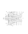
- the figure which expanded a part of clutch actuator of this embodiment is shown.
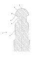
- the retaining member of the clutch actuator of this embodiment is shown.
- Another example of the push rod 6 is shown.
- FIG. 1 shows a sectional view of the clutch actuator of the present embodiment.
- the clutch actuator 1 of the present embodiment includes a power cylinder 2, a body 3, a control valve 4, a guard 5, and a clutch operation push rod 6.
- the power cylinder 2 includes a substantially cylindrical cylinder shell 21, a cover 22 that covers the front of the cylinder shell 21 in an annular shape, a pressure piston 81 and an atmosphere chamber 82 in the cylinder shell 21, and a slidable power piston. 23 and a return spring 24 that urges the power piston 23 toward the atmosphere chamber 82 side.
- the front of the cylinder shell 21 corresponding to the left in FIG. 1 is covered with a cover 22 in an annular shape, and the opposite rear is covered with a body 3.
- the cover 22 is formed with a hole in the center, and the guard 5 is fitted therein. Therefore, the opening in front of the cylinder shell 21 is closed by the cover 22 that covers the ring and the guard 5 that is fitted in the center of the cover 22.
- the cylinder shell 21 and the cover 22 may be integrally formed with a single member.
- the power piston 23 has a plate portion 23a that divides the inside of the cylinder shell 21 into a rear pressure chamber 81 and a front air chamber 82, and a rod portion 23b attached to the rear side from the center of the plate portion 23a.
- the power piston 23 is movable in the front-rear direction.
- a seal member or the like is attached to a sliding portion with the cylinder shell 21 on the outer periphery of the plate portion 23a.
- a concave push rod tip storage portion 23c for supporting the push rod 6 is formed.
- An annular recess 23d for installing the return spring 24 is formed on the outer periphery of the rod portion 23b on the rear side of the plate portion 23a.
- the return spring 24 is installed in the annular recess 23d, connects the body 3 and the power piston 23, and biases the power piston 23 toward the atmosphere chamber 82 side.
- the control valve 4 is attached to the body 3.
- the control valve 4 controls the air pressure in the pressure chamber 81 by adjusting the amount of air sucked and exhausted in an air tank (not shown) and the pressure chamber 81.
- the guard 5 is a part that guards the push rod 6 and is attached to the cover 22.
- the guard 5 is a cylindrical member having a bellows structure made of a flexible material such as rubber, and a hole through which the push rod 6 is inserted is formed in the front.
- control valve 4 In order to operate the clutch, the control valve 4 is controlled to supply air to the pressure chamber 81 in the cylinder shell 21. When compressed air is supplied to the pressure chamber 81, the power piston 23 moves forward. When the power piston 23 moves forward, the push rod 6 moves forward. Then, the clutch is disengaged by the movement of the push rod 6.
- the control valve 4 is controlled and air is exhausted from the pressure chamber 81. Then, the power piston 23 moves backward. When the power piston 23 moves rearward, the push rod 6 moves rearward. Then, the clutch is connected by the movement of the push rod 6.
- a retaining member 7 is used in the assembly portion of the power piston 23 and the push rod 6 of the clutch actuator 1 of the present embodiment.
- FIG. 2 shows an enlarged view of a part of the clutch actuator 1 of the present embodiment.
- the push rod 6 is inserted into a push rod tip storage portion 23 c formed on the power piston 23.
- the portion inserted into the push rod tip storage portion 23c on the rear side of the push rod 6 has a diameter from the tip portion 6a that expands from the rear tip 6a 1 to the front side and the front end 6a 2 of the tip portion 6a.
- the push rod tip storage portion 23c of the power piston 23 is formed with a retaining member storage portion 23e that is concave in the radial direction from the circumferential surface.
- the holding member 8 is installed so as to hold the tip portion 6 a of the push rod 6.
- FIG. 3 shows a retaining member of the clutch actuator of the present embodiment.
- the retaining member 7 is an annular member having a thickness enough to be accommodated in the retaining member accommodating portion 23e, and is formed from an elastic member such as rubber or a material such as soft resin. As shown in FIG. 3, the retaining member 7 of the present embodiment has alternately formed body portions 7 a that are formed in an annular shape and curved portions 7 b that protrude from the body portion 7 a to the outer peripheral side. A curved concave portion 7c is formed on the inner peripheral side of the curved portion 7b. In addition, the main-body part 7a may be formed in linear form, and may connect the curved part 7b.
- the retaining member 7 is detachably attached to the retaining member storage portion 23e of the power piston 23.
- the retaining member 7 is formed by bending or contracting the main body portion 7a and the curved portion 7b according to the shape as shown in FIG. 3 and the characteristics of the materials described above, thereby preventing the retaining member accommodating portion 23e of the push rod tip accommodating portion 23c. It is possible to insert it easily.
- the holding member 8 is installed in the innermost part of the push rod tip storage portion 23c in advance. Subsequently, the retaining member 7 is attached to the retaining member accommodating portion 23 e of the power piston 23.
- the push rod 6 is inserted into the push rod tip storage portion 23c of the power piston 23.
- the tip 6a comes into contact with the retaining member 7 and feels resistance.
- the push rod 6 is continuously pushed as it is, the tip portion 6a is spherical, the retaining member 7 is easily deformed, and further, a part of the curved recess 7c of the retaining member 7 and the tip portion 6a are not in contact with each other.
- the distal end portion 6 a easily passes through the retaining member 7, and the push rod 6 is easily assembled to the power piston 23.
- the clutch actuator 1 of this embodiment may pull out the push rod 6 from the power piston 23 at the time of inspection or replacement.
- the tip 6a is spherical, the retaining member 7 is easily deformed, and a part of the curved concave portion 7c of the retaining member 7 is formed.
- the tip portion 6 a easily passes through the retaining member 7, and the push rod 6 comes out of the power piston 23.
- the retaining member 7 does not come out of the retaining member storage portion 23e when the curved portion 7b is caught by the power piston 23.
- the clutch actuator 1 may be lifted by holding the push rod 6. At this time, if the push rod 6 comes off after the clutch actuator 1 is lifted, it may fall on the carrier's foot. Therefore, it is preferable that the resistance force by the retaining member 7 is such that the push rod 6 is pulled out by its own weight.
- the clutch actuator 1 of the present embodiment it is possible to accurately adjust the resistance force when removing the push rod 6 while having the effect of preventing the push rod 6 from coming off from the clutch actuator 1. Moreover, it becomes possible to adjust the resistance force when the push rod 6 comes off.
- FIG. 4 shows another example of the push rod 6.
- the clutch actuator 1 of the example shown in FIG. 4 has a reduced diameter portion 6d that gradually decreases in diameter from the distal end portion 6a toward the small diameter portion 6b so that the push rod 6 can easily pass through the retaining member 7 when pulled out.
- the diameter-reduced portion 6d does not have to be reduced in diameter at a constant rate, and the diameter may be reduced while changing the rate. Further, the reduced diameter portion 6d may have a section having a constant diameter in part.
- the clutch actuator 1 is formed on the cylinder shell 21, the power piston 23 that partitions the inside of the cylinder shell 21 into the pressure chamber 81 and the atmospheric chamber 82, and the power piston 23.
- the push rod 6 can be easily inserted and removed.
- the retaining member 7 is formed by alternately forming the annular main body portion 7a and the curved portion 7b protruding from the main body portion 7a to the outer peripheral side, so the number or size of the curved portions 7b is adjusted. By doing so, the retaining member 7 can be easily attached to and detached from the power piston 23. Moreover, it becomes possible to adjust the resistance force when the push rod 6 comes off.
- the retaining member 7 is formed with the curved concave portion 7c on the inner peripheral side of the curved portion 7b, the resistance force when the push rod 6 is pulled out can be adjusted.
- the portion of the push rod 6 to be inserted into the push rod tip storage portion 23c includes a tip portion 6a whose diameter increases from the tip 6a 1, a small diameter portion 6b whose diameter is smaller than the end portion 6a 2 of the tip portion 6a, and a small diameter portion. And a part of the retaining member 7 is housed in the small-diameter portion 6b, so that it is possible to finely adjust the resistance force when the push rod 6 comes off. Become.
- the push rod 6 has the reduced diameter portion 6d that gradually decreases in diameter from the distal end portion 6a toward the small diameter portion 6b, it becomes possible to finely adjust the resistance force when the push rod 6 is pulled out. .
Landscapes
- Engineering & Computer Science (AREA)
- General Engineering & Computer Science (AREA)
- Mechanical Engineering (AREA)
- Hydraulic Clutches, Magnetic Clutches, Fluid Clutches, And Fluid Joints (AREA)
- Actuator (AREA)
Abstract
プッシュロッドをクラッチアクチュエータから抜け止めさせる効果を備えつつ、抜き取る際には抵抗力を的確に調整して抜くことが可能なクラッチアクチュエータを提供する。 クラッチアクチュエータ1は、シリンダシェル21と、シリンダシェル21内を圧力室及び大気室に区画するパワーピストン23と、パワーピストン23に形成される凹状のプッシュロッド先端収納部23cに一部挿入されるプッシュロッド6と、プッシュロッド先端収納部23cの周面から径方向に凹状に形成される抜止部材収納部23eに一部が収納される抜止部材7と、を備えることを特徴とする。
Description
本発明は、入力を所定のサーボ比で倍力して大きな出力を発生するクラッチアクチュエータの技術分野に関するものである。
自動車のクラッチシステムにおいては、アクチュエータが用いられている(例えば、特許文献1参照)。特許文献1には、空圧導入室に圧縮エアが供給されることによりクラッチを切断するクラッチアクチュエータに関する技術が記載されている。
特許文献1に記載されたようなクラッチアクチュエータにおいて、点検又は交換するためプッシュロッドをクラッチアクチュエータから抜き取ることが可能な構造とする必要がある。しかしながら、クラッチアクチュエータを持ち運ぶ際に、プッシュロッドを持って持ち上げる場合、プッシュロッドがクラッチアクチュエータから抜けてしまい、シリンダシェル側の部品が落下し、運搬者の足を直撃する可能性があった。
本発明はこのような事情に鑑みてなされたものであって、その目的は、プッシュロッドをクラッチアクチュエータから抜け止めさせる効果を備えつつ、抜き取る際には抵抗力を的確に調整して抜くことが可能なクラッチアクチュエータを提供することである。
前述の課題を解決するために、本発明の実施形態にかかるクラッチアクチュエータは、シリンダシェルと、前記シリンダシェル内を圧力室及び大気室に区画するパワーピストンと、前記パワーピストンに形成される凹状のプッシュロッド先端収納部に一部が挿入されるプッシュロッドと、前記プッシュロッド先端収納部の周面から径方向に凹状に形成される抜止部材収納部に一部が収納される抜止部材と、を備えることを特徴とする。
また、前記抜止部材は、弾性を有することを特徴とする。
また、前記抜止部材は、環状に形成される本体部と、前記本体部から外周側に突出する湾曲部と、が交互に形成されることを特徴とする。
また、前記抜止部材は、前記湾曲部の内周側に、湾曲凹部が形成されることを特徴とする。
また、前記プッシュロッドの前記プッシュロッド先端収納部に挿入される部分は、先端から拡径する先端部と、前記先端部の端部より径が小さい小径部と、前記小径部より径が大きい大径部と、を有し、前記抜止部材の一部は、前記小径部に収納されることを特徴とする。
また、前記プッシュロッドは、前記先端部から前記小径部へ向かうにつれて徐々に径が小さくなる縮径部を有することを特徴とする。
前述の課題を解決するために、本発明の実施形態にかかるクラッチアクチュエータは、シリンダシェルと、前記シリンダシェル内を圧力室及び大気室に区画するパワーピストンと、前記パワーピストンに形成される凹状のプッシュロッド先端収納部に一部が挿入されるプッシュロッドと、前記プッシュロッド先端収納部の周面から径方向に凹状に形成される抜止部材収納部に一部が収納される抜止部材と、を備えるので、プッシュロッドをクラッチアクチュエータから抜け止めさせる効果を備えつつ、抜き取る際には抵抗力を的確に調整して抜くことが可能となる。
また、前記抜止部材は、弾性を有するので、プッシュロッドの抜き差しを容易に行うことが可能となる。
また、前記抜止部材は、環状に形成される本体部と、前記本体部から外周側に突出する湾曲部と、が交互に形成されるので、湾曲部の数又は大きさ等を調整することによって、パワーピストンに対して抜止部材を容易に着脱することが可能となる。また、プッシュロッドが抜ける際の抵抗力を調整することが可能となる。
また、前記抜止部材は、前記湾曲部の内周側に、湾曲凹部が形成されるので、プッシュロッドが抜ける際の抵抗力を調整することが可能となる。
また、前記プッシュロッドの前記プッシュロッド先端収納部に挿入される部分は、先端から前方側へ拡径する先端部と、前記先端部の端部より径が小さい小径部と、前記小径部より径が大きい大径部と、を有し、前記抜止部材の一部は、前記小径部に収納されるので、プッシュロッドが抜ける際の抵抗力をより細かく調整することが可能となる。
また、前記プッシュロッドは、前記先端部から前記小径部へ向かうにつれて徐々に径が小さくなる縮径部を有するので、プッシュロッドが抜ける際の抵抗力をより細かく調整することが可能となる。
以下、図面を用いて本発明の実施の形態について説明する。なお、本発明の明細書の記載において、前後方向の関係は、クラッチアクチュエータの作動時にピストンが移動する方向を「前」、作動解除時にピストンが戻る方向を「後」とする。
図1は、本実施形態のクラッチアクチュエータの断面図を示す。
本実施形態のクラッチアクチュエータ1は、パワーシリンダ2と、ボディー3と、コントロールバルブ4と、ガード5と、クラッチ操作用プッシュロッド6と、を備える。
パワーシリンダ2は、略円筒状のシリンダシェル21と、シリンダシェル21の前方を環状に覆うカバー22と、シリンダシェル21内を圧力室81と大気室82に区画すると共に、摺動可能なパワーピストン23と、パワーピストン23を大気室82側に付勢するリターンスプリング24と、を有する。
シリンダシェル21は、図1における左方向にあたる前方はカバー22によって環状に覆われ、反対の後方はボディー3によって覆われている。カバー22は、中央に孔が形成され、ガード5が嵌め込まれる。したがって、シリンダシェル21の前方の開口は、環状に覆うカバー22とカバー22の中央に嵌め込まれるガード5によって、塞がれる。なお、シリンダシェル21とカバー22は一つの部材で一体に形成されてもよい。
パワーピストン23は、シリンダシェル21内を後方の圧力室81と前方の大気室82に区画するプレート部23aとプレート部23aの中心から後方側に取り付けられるロッド部23bと、を有する。パワーピストン23は、前後方向に移動可能である。
プレート部23aの外周のシリンダシェル21との摺動部分には、シール部材等が取り付けられる。プレート部23aの前方側の中心には、プッシュロッド6が支持される凹状のプッシュロッド先端収納部23cが形成される。また、プレート部23aの後方側のロッド部23bの外周には、リターンスプリング24を設置する環状凹部23dが形成される。
リターンスプリング24は、環状凹部23dに設置され、ボディー3とパワーピストン23を連結し、パワーピストン23を大気室82側に付勢する。
ボディー3には、コントロールバルブ4が取り付けられる。コントロールバルブ4は、図示しないエアタンク等と圧力室81で吸排気される空気の量を調節して、圧力室81の気圧を制御する。
ガード5は、プッシュロッド6をガードする部分であって、カバー22に取り付けられる。ガード5は、ゴム等の可撓性を有する材料からなる蛇腹構造の筒状の部材であり、前方にプッシュロッド6を挿通する孔が形成される。
次に、本実施形態のクラッチアクチュエータの作動について説明する。
クラッチを作動させるには、コントロールバルブ4を制御してシリンダシェル21内の圧力室81に空気を供給する。圧力室81に圧縮エアが供給されると、パワーピストン23が前方へ移動する。パワーピストン23が前方へ移動すると、プッシュロッド6が前方へ移動する。そして、プッシュロッド6の移動によって、クラッチが切断される。
クラッチを非作動とするには、コントロールバルブ4を制御して、圧力室81からエアを排気する。すると、パワーピストン23が後方へ移動する。パワーピストン23が後方へ移動すると、プッシュロッド6が後方へ移動する。そして、プッシュロッド6の移動によって、クラッチが接続される。
ここで、本実施形態のクラッチアクチュエータ1のパワーピストン23とプッシュロッド6の組み付けについて説明する。本実施形態のクラッチアクチュエータ1のパワーピストン23とプッシュロッド6の組み付け部分には、抜止部材7が用いられる。
図2は、本実施形態のクラッチアクチュエータ1の一部を拡大した図を示す。
プッシュロッド6は、パワーピストン23に形成されたプッシュロッド先端収納部23cに挿入される。プッシュロッド6の後方側のプッシュロッド先端収納部23cに挿入される部分は、後方側の先端6a1から前方側へ拡径する先端部6aと、先端部6aの前方
の端部6a2より径が小さい小径部6bと、小径部6bの前方端より径が大きい大径部6
cと、を有する。
の端部6a2より径が小さい小径部6bと、小径部6bの前方端より径が大きい大径部6
cと、を有する。
パワーピストン23のプッシュロッド先端収納部23cには、周面から径方向に凹状の抜止部材収納部23eが形成される。また、プッシュロッド先端収納部23cの最も奥には、抑え部材8がプッシュロッド6の先端部6aを抑えるように設置される。抑え部材8を設置することによって、プッシュロッド6をぶれないように抑えることが可能となる。
図3は、本実施形態のクラッチアクチュエータの抜止部材を示す。
抜止部材7は、抜止部材収納部23eに収納される程度の厚みを有する環状の部材であり、ゴム等の弾性部材又は軟性の樹脂等の材料から形成される。図3に示すように、本実施形態の抜止部材7は、環状に形成される本体部7aと、本体部7aから外周側に突出する湾曲部7bと、が交互に形成される。湾曲部7bの内周側には、湾曲凹部7cが形成される。なお、本体部7aは、直線状に形成され、湾曲部7bを連結してもよい。
抜止部材7は、パワーピストン23の抜止部材収納部23eに着脱可能に取り付けられる。抜止部材7は、図3に示すような形状及び前述した材料の特性によって、本体部7a及び湾曲部7bを折り曲げたり、収縮したりすることで、プッシュロッド先端収納部23cの抜止部材収納部23eに容易に挿入することが可能である。
このような構造の本実施形態のクラッチアクチュエータのパワーピストン23とプッシュロッド6の組み付けるには、あらかじめ抑え部材8をプッシュロッド先端収納部23cの最も奥に設置する。続いて、抜止部材7をパワーピストン23の抜止部材収納部23eに取り付ける。
次に、プッシュロッド6をパワーピストン23のプッシュロッド先端収納部23cに挿入する。挿入の際、先端部6aが抜止部材7に接触し、抵抗を感じる。しかしながら、プッシュロッド6をそのまま押し続けると、先端部6aが球状であることと、抜止部材7が容易に変形すること、さらに、抜止部材7の湾曲凹部7cの一部と先端部6aが非接触になることによって、先端部6aが抜止部材7を通過し易く、プッシュロッド6がパワーピストン23に容易に組み付けられる。
また、本実施形態のクラッチアクチュエータ1は、点検又は交換時に、パワーピストン23からプッシュロッド6を抜き取ることがある。パワーピストン23からプッシュロッド6を抜き取る場合、プッシュロッド6を引っ張ると、先端部6aが球状であることと、抜止部材7が容易に変形すること、さらに、抜止部材7の湾曲凹部7cの一部と先端部6aが非接触になることによって、先端部6aが抜止部材7を通過し易く、プッシュロッド6がパワーピストン23から抜ける。ここで、抜止部材7は、湾曲部7bがパワーピストン23に引っ掛かることで抜止部材収納部23eから抜けないことが好ましい。
また、本実施形態のクラッチアクチュエータ1では、プッシュロッド6を持って、クラッチアクチュエータ1を持ち上げる場合がある。この時、クラッチアクチュエータ1を持ち上げた後にプッシュロッド6が抜けてしまうと、運搬者の足に落下するおそれがある。そこで、抜止部材7による抵抗力は、プッシュロッド6がクラッチアクチュエータ1の自重によって抜ける程度であることが好ましい。
このように、本実施形態のクラッチアクチュエータ1によれば、プッシュロッド6をクラッチアクチュエータ1から抜け止めさせる効果を備えつつ、抜き取る際には抵抗力を的確に調整して抜くことが可能となる。また、プッシュロッド6が抜ける際の抵抗力を調整することが可能となる。
図4は、プッシュロッド6の他の例を示す。
図4に示す例のクラッチアクチュエータ1では、引き抜き時にプッシュロッド6が抜止部材7を容易に通過できるように、先端部6aから小径部6bへ向かうにつれて徐々に径が小さくなる縮径部6dを有する。なお、縮径部6dは、一定の割合で径が小さくなる必要はなく、割合を変化させながら径が小さくなってもよい。また、縮径部6dは、一部に径が一定の区間を有してもよい。
以上、説明したように、本実施形態によれば、クラッチアクチュエータ1は、シリンダシェル21と、シリンダシェル21内を圧力室81及び大気室82に区画するパワーピストン23と、パワーピストン23に形成されるプッシュロッド先端収納部23cに挿入されるプッシュロッド6と、プッシュロッド先端収納部23cの周面から径方向に凹状に形成される抜止部材収納部23eに一部が収納される抜止部材7と、を備えるので、プッシュロッド6をクラッチアクチュエータ1から抜け止めさせる効果を備えつつ、抜き取る際には抵抗力を的確に調整して抜くことが可能となる。
また、抜止部材7は、弾性を有するので、プッシュロッド6の抜き差しを容易に行うことが可能となる。
また、抜止部材7は、環状に形成される本体部7aと、本体部7aから外周側に突出する湾曲部7bと、が交互に形成されるので、湾曲部7bの数又は大きさ等を調整することによって、パワーピストン23に対して抜止部材7を容易に着脱することが可能となる。また、プッシュロッド6が抜ける際の抵抗力を調整することが可能となる。
また、抜止部材7は、湾曲部7bの内周側に、湾曲凹部7cが形成されるので、プッシュロッド6が抜ける際の抵抗力を調整することが可能となる。
また、プッシュロッド6のプッシュロッド先端収納部23cに挿入される部分は、先端6a1から拡径する先端部6aと、先端部6aの端部6a2より径が小さい小径部6bと、小径部6bより径が大きい大径部6cと、を有し、抜止部材7の一部は、小径部6bに収納されるので、プッシュロッド6が抜ける際の抵抗力をより細かく調整することが可能となる。
また、プッシュロッド6は、先端部6aから小径部6bへ向かうにつれて徐々に径が小さくなる縮径部6dを有するので、プッシュロッド6が抜ける際の抵抗力をより細かく調整することが可能となる。
以上、本発明の種々の実施形態について説明したが、本発明はこれらの実施形態のみに限られるものではなく、発明の範囲を超えない限り、それぞれの実施形態の構成を適宜変更した構成及びそれぞれの実施形態の構成を適宜組み合わせた構成の実施形態も本発明の範疇となるものである。
Claims (6)
- シリンダシェルと、
前記シリンダシェル内を圧力室及び大気室に区画するパワーピストンと、
前記パワーピストンに形成される凹状のプッシュロッド先端収納部に一部が挿入されるプッシュロッドと、
前記プッシュロッド先端収納部の周面から径方向に凹状に形成される抜止部材収納部に一部が収納される抜止部材と、
を備える
ことを特徴とするクラッチアクチュエータ。 - 前記抜止部材は、弾性を有する
ことを特徴とする請求項1に記載のクラッチアクチュエータ。 - 前記抜止部材は、
環状に形成される本体部と、
前記本体部から外周側に突出する湾曲部と、
が交互に形成される
ことを特徴とする請求項1又は2に記載のクラッチアクチュエータ。 - 前記抜止部材は、前記湾曲部の内周側に、湾曲凹部が形成される
ことを特徴とする請求項3に記載のクラッチアクチュエータ。 - 前記プッシュロッドの前記プッシュロッド先端収納部に挿入される部分は、
先端から拡径する先端部と、
前記先端部の端部より径が小さい小径部と、
前記小径部より径が大きい大径部と、
を有し、
前記抜止部材の一部は、前記小径部に収納される
ことを特徴とする請求項1乃至請求項4のいずれか1つに記載のクラッチアクチュエータ。 - 前記プッシュロッドは、前記先端部から前記小径部へ向かうにつれて徐々に径が小さくなる縮径部を有する
ことを特徴とする請求項5に記載のクラッチアクチュエータ。
Priority Applications (3)
| Application Number | Priority Date | Filing Date | Title |
|---|---|---|---|
| CN201480079582.5A CN106460959A (zh) | 2014-06-06 | 2014-06-06 | 离合器致动器 |
| PCT/JP2014/065036 WO2015186235A1 (ja) | 2014-06-06 | 2014-06-06 | クラッチアクチュエータ |
| JP2016525641A JPWO2015186235A1 (ja) | 2014-06-06 | 2014-06-06 | クラッチアクチュエータ |
Applications Claiming Priority (1)
| Application Number | Priority Date | Filing Date | Title |
|---|---|---|---|
| PCT/JP2014/065036 WO2015186235A1 (ja) | 2014-06-06 | 2014-06-06 | クラッチアクチュエータ |
Publications (1)
| Publication Number | Publication Date |
|---|---|
| WO2015186235A1 true WO2015186235A1 (ja) | 2015-12-10 |
Family
ID=54766330
Family Applications (1)
| Application Number | Title | Priority Date | Filing Date |
|---|---|---|---|
| PCT/JP2014/065036 Ceased WO2015186235A1 (ja) | 2014-06-06 | 2014-06-06 | クラッチアクチュエータ |
Country Status (3)
| Country | Link |
|---|---|
| JP (1) | JPWO2015186235A1 (ja) |
| CN (1) | CN106460959A (ja) |
| WO (1) | WO2015186235A1 (ja) |
Citations (4)
| Publication number | Priority date | Publication date | Assignee | Title |
|---|---|---|---|---|
| US2933357A (en) * | 1957-07-12 | 1960-04-19 | Chrysler Corp | Vehicle brake |
| JPH0777223A (ja) * | 1993-09-08 | 1995-03-20 | Jidosha Kiki Co Ltd | クラッチ操作装置 |
| JPH0814273A (ja) * | 1994-06-29 | 1996-01-16 | Aisin Seiki Co Ltd | クラッチレリーズシリンダ |
| US6470791B1 (en) * | 1997-11-25 | 2002-10-29 | Luk Lamellen Und Kupplungsbau Beteiligungs Kg | Master cylinder |
Family Cites Families (5)
| Publication number | Priority date | Publication date | Assignee | Title |
|---|---|---|---|---|
| US1543498A (en) * | 1924-03-21 | 1925-06-23 | Hammond Clayson Ross | Piston and connecting rod for engines |
| US1717520A (en) * | 1925-06-05 | 1929-06-18 | Frank C Reilly | Compressor |
| US2124762A (en) * | 1935-06-10 | 1938-07-26 | Bendix Aviat Corp | Brake |
| US2155207A (en) * | 1935-11-27 | 1939-04-18 | Stocker William | Brake construction |
| CN200949612Y (zh) * | 2006-08-31 | 2007-09-19 | 万安集团诸暨汽车零部件有限公司 | 一种汽车离合器助力器总成 |
-
2014
- 2014-06-06 JP JP2016525641A patent/JPWO2015186235A1/ja active Pending
- 2014-06-06 CN CN201480079582.5A patent/CN106460959A/zh active Pending
- 2014-06-06 WO PCT/JP2014/065036 patent/WO2015186235A1/ja not_active Ceased
Patent Citations (4)
| Publication number | Priority date | Publication date | Assignee | Title |
|---|---|---|---|---|
| US2933357A (en) * | 1957-07-12 | 1960-04-19 | Chrysler Corp | Vehicle brake |
| JPH0777223A (ja) * | 1993-09-08 | 1995-03-20 | Jidosha Kiki Co Ltd | クラッチ操作装置 |
| JPH0814273A (ja) * | 1994-06-29 | 1996-01-16 | Aisin Seiki Co Ltd | クラッチレリーズシリンダ |
| US6470791B1 (en) * | 1997-11-25 | 2002-10-29 | Luk Lamellen Und Kupplungsbau Beteiligungs Kg | Master cylinder |
Also Published As
| Publication number | Publication date |
|---|---|
| JPWO2015186235A1 (ja) | 2017-04-20 |
| CN106460959A (zh) | 2017-02-22 |
Similar Documents
| Publication | Publication Date | Title |
|---|---|---|
| USD899980S1 (en) | Vehicle front diffusor | |
| USD865621S1 (en) | Automotive wheel | |
| AR095753A1 (es) | Cartucho de recarga presurizado provisto con válvula de salida | |
| KR101777666B1 (ko) | 공기압축기 장치 | |
| USD865620S1 (en) | Automotive wheel | |
| EP4310401A3 (en) | Combustor assembly for a turbine engine | |
| JP2019099044A5 (ja) | ||
| JP2011515267A5 (ja) | ||
| WO2015186235A1 (ja) | クラッチアクチュエータ | |
| JP5251294B2 (ja) | シャープペンシル | |
| US20160311104A1 (en) | Single-shot type air hammer tool and method of adjusting striking force thereof | |
| CN103256272B (zh) | 气缸 | |
| JP5856678B2 (ja) | ダンパー | |
| JP6223081B2 (ja) | 内視鏡通気口金 | |
| JP2018155197A5 (ja) | ||
| JP6338997B2 (ja) | 打ち込み工具 | |
| JP2010207940A (ja) | つかみ装置 | |
| US20090255523A1 (en) | Shooting mechanism for paint ball gun | |
| US9841102B2 (en) | Key fob seal structure with pressure release capability | |
| USD888891S1 (en) | Jet lavage | |
| US20140263917A1 (en) | Small-sized portable vacuum-holding device | |
| JP6188549B2 (ja) | クラッチ倍力装置 | |
| JP6226738B2 (ja) | クラッチ倍力装置 | |
| US9926948B1 (en) | Transportation guard for pyrotechnic actuators | |
| JP7093537B2 (ja) | ガス燃焼式打ち込み工具用の燃料容器 |
Legal Events
| Date | Code | Title | Description |
|---|---|---|---|
| 121 | Ep: the epo has been informed by wipo that ep was designated in this application |
Ref document number: 14893803 Country of ref document: EP Kind code of ref document: A1 |
|
| ENP | Entry into the national phase |
Ref document number: 2016525641 Country of ref document: JP Kind code of ref document: A |
|
| NENP | Non-entry into the national phase |
Ref country code: DE |
|
| 122 | Ep: pct application non-entry in european phase |
Ref document number: 14893803 Country of ref document: EP Kind code of ref document: A1 |