WO2015182543A1 - 懸架コイルばね - Google Patents
懸架コイルばね Download PDFInfo
- Publication number
- WO2015182543A1 WO2015182543A1 PCT/JP2015/064882 JP2015064882W WO2015182543A1 WO 2015182543 A1 WO2015182543 A1 WO 2015182543A1 JP 2015064882 W JP2015064882 W JP 2015064882W WO 2015182543 A1 WO2015182543 A1 WO 2015182543A1
- Authority
- WO
- WIPO (PCT)
- Prior art keywords
- coil spring
- end winding
- seat
- suspension coil
- spring
- Prior art date
Links
- 239000000725 suspension Substances 0.000 title claims abstract description 117
- 238000004804 winding Methods 0.000 claims description 77
- 235000019506 cigar Nutrition 0.000 claims description 2
- 235000019504 cigarettes Nutrition 0.000 claims 1
- 239000006096 absorbing agent Substances 0.000 abstract description 23
- 230000035939 shock Effects 0.000 abstract description 23
- 230000000284 resting effect Effects 0.000 abstract 2
- 230000003247 decreasing effect Effects 0.000 abstract 1
- 238000006243 chemical reaction Methods 0.000 description 21
- 238000006557 surface reaction Methods 0.000 description 17
- 238000005452 bending Methods 0.000 description 10
- 238000010586 diagram Methods 0.000 description 7
- 230000004048 modification Effects 0.000 description 6
- 238000012986 modification Methods 0.000 description 6
- 230000008859 change Effects 0.000 description 4
- 230000009471 action Effects 0.000 description 2
- 230000008901 benefit Effects 0.000 description 1
- 230000006835 compression Effects 0.000 description 1
- 238000007906 compression Methods 0.000 description 1
- 230000007423 decrease Effects 0.000 description 1
- 230000000694 effects Effects 0.000 description 1
- 239000012530 fluid Substances 0.000 description 1
- 238000009434 installation Methods 0.000 description 1
- 238000004519 manufacturing process Methods 0.000 description 1
- 230000002093 peripheral effect Effects 0.000 description 1
- 230000009467 reduction Effects 0.000 description 1
- 238000000926 separation method Methods 0.000 description 1
- 230000007704 transition Effects 0.000 description 1
Images


Classifications
-
- B—PERFORMING OPERATIONS; TRANSPORTING
- B60—VEHICLES IN GENERAL
- B60G—VEHICLE SUSPENSION ARRANGEMENTS
- B60G11/00—Resilient suspensions characterised by arrangement, location or kind of springs
- B60G11/14—Resilient suspensions characterised by arrangement, location or kind of springs having helical, spiral or coil springs only
- B60G11/16—Resilient suspensions characterised by arrangement, location or kind of springs having helical, spiral or coil springs only characterised by means specially adapted for attaching the spring to axle or sprung part of the vehicle
-
- B—PERFORMING OPERATIONS; TRANSPORTING
- B60—VEHICLES IN GENERAL
- B60G—VEHICLE SUSPENSION ARRANGEMENTS
- B60G15/00—Resilient suspensions characterised by arrangement, location or type of combined spring and vibration damper, e.g. telescopic type
- B60G15/02—Resilient suspensions characterised by arrangement, location or type of combined spring and vibration damper, e.g. telescopic type having mechanical spring
- B60G15/06—Resilient suspensions characterised by arrangement, location or type of combined spring and vibration damper, e.g. telescopic type having mechanical spring and fluid damper
- B60G15/062—Resilient suspensions characterised by arrangement, location or type of combined spring and vibration damper, e.g. telescopic type having mechanical spring and fluid damper the spring being arranged around the damper
- B60G15/063—Resilient suspensions characterised by arrangement, location or type of combined spring and vibration damper, e.g. telescopic type having mechanical spring and fluid damper the spring being arranged around the damper characterised by the mounting of the spring on the damper
-
- B—PERFORMING OPERATIONS; TRANSPORTING
- B60—VEHICLES IN GENERAL
- B60G—VEHICLE SUSPENSION ARRANGEMENTS
- B60G3/00—Resilient suspensions for a single wheel
- B60G3/18—Resilient suspensions for a single wheel with two or more pivoted arms, e.g. parallelogram
- B60G3/28—Resilient suspensions for a single wheel with two or more pivoted arms, e.g. parallelogram at least one of the arms itself being resilient, e.g. leaf spring
-
- F—MECHANICAL ENGINEERING; LIGHTING; HEATING; WEAPONS; BLASTING
- F16—ENGINEERING ELEMENTS AND UNITS; GENERAL MEASURES FOR PRODUCING AND MAINTAINING EFFECTIVE FUNCTIONING OF MACHINES OR INSTALLATIONS; THERMAL INSULATION IN GENERAL
- F16F—SPRINGS; SHOCK-ABSORBERS; MEANS FOR DAMPING VIBRATION
- F16F1/00—Springs
- F16F1/02—Springs made of steel or other material having low internal friction; Wound, torsion, leaf, cup, ring or the like springs, the material of the spring not being relevant
- F16F1/025—Springs made of steel or other material having low internal friction; Wound, torsion, leaf, cup, ring or the like springs, the material of the spring not being relevant characterised by having a particular shape
-
- F—MECHANICAL ENGINEERING; LIGHTING; HEATING; WEAPONS; BLASTING
- F16—ENGINEERING ELEMENTS AND UNITS; GENERAL MEASURES FOR PRODUCING AND MAINTAINING EFFECTIVE FUNCTIONING OF MACHINES OR INSTALLATIONS; THERMAL INSULATION IN GENERAL
- F16F—SPRINGS; SHOCK-ABSORBERS; MEANS FOR DAMPING VIBRATION
- F16F1/00—Springs
- F16F1/02—Springs made of steel or other material having low internal friction; Wound, torsion, leaf, cup, ring or the like springs, the material of the spring not being relevant
- F16F1/04—Wound springs
- F16F1/047—Wound springs characterised by varying pitch
-
- F—MECHANICAL ENGINEERING; LIGHTING; HEATING; WEAPONS; BLASTING
- F16—ENGINEERING ELEMENTS AND UNITS; GENERAL MEASURES FOR PRODUCING AND MAINTAINING EFFECTIVE FUNCTIONING OF MACHINES OR INSTALLATIONS; THERMAL INSULATION IN GENERAL
- F16F—SPRINGS; SHOCK-ABSORBERS; MEANS FOR DAMPING VIBRATION
- F16F1/00—Springs
- F16F1/02—Springs made of steel or other material having low internal friction; Wound, torsion, leaf, cup, ring or the like springs, the material of the spring not being relevant
- F16F1/04—Wound springs
- F16F1/06—Wound springs with turns lying in cylindrical surfaces
-
- F—MECHANICAL ENGINEERING; LIGHTING; HEATING; WEAPONS; BLASTING
- F16—ENGINEERING ELEMENTS AND UNITS; GENERAL MEASURES FOR PRODUCING AND MAINTAINING EFFECTIVE FUNCTIONING OF MACHINES OR INSTALLATIONS; THERMAL INSULATION IN GENERAL
- F16F—SPRINGS; SHOCK-ABSORBERS; MEANS FOR DAMPING VIBRATION
- F16F1/00—Springs
- F16F1/02—Springs made of steel or other material having low internal friction; Wound, torsion, leaf, cup, ring or the like springs, the material of the spring not being relevant
- F16F1/04—Wound springs
- F16F1/12—Attachments or mountings
- F16F1/123—Attachments or mountings characterised by the ends of the spring being specially adapted, e.g. to form an eye for engagement with a radial insert
-
- F—MECHANICAL ENGINEERING; LIGHTING; HEATING; WEAPONS; BLASTING
- F16—ENGINEERING ELEMENTS AND UNITS; GENERAL MEASURES FOR PRODUCING AND MAINTAINING EFFECTIVE FUNCTIONING OF MACHINES OR INSTALLATIONS; THERMAL INSULATION IN GENERAL
- F16F—SPRINGS; SHOCK-ABSORBERS; MEANS FOR DAMPING VIBRATION
- F16F9/00—Springs, vibration-dampers, shock-absorbers, or similarly-constructed movement-dampers using a fluid or the equivalent as damping medium
- F16F9/32—Details
-
- B—PERFORMING OPERATIONS; TRANSPORTING
- B60—VEHICLES IN GENERAL
- B60G—VEHICLE SUSPENSION ARRANGEMENTS
- B60G15/00—Resilient suspensions characterised by arrangement, location or type of combined spring and vibration damper, e.g. telescopic type
- B60G15/02—Resilient suspensions characterised by arrangement, location or type of combined spring and vibration damper, e.g. telescopic type having mechanical spring
- B60G15/06—Resilient suspensions characterised by arrangement, location or type of combined spring and vibration damper, e.g. telescopic type having mechanical spring and fluid damper
- B60G15/062—Resilient suspensions characterised by arrangement, location or type of combined spring and vibration damper, e.g. telescopic type having mechanical spring and fluid damper the spring being arranged around the damper
-
- B—PERFORMING OPERATIONS; TRANSPORTING
- B60—VEHICLES IN GENERAL
- B60G—VEHICLE SUSPENSION ARRANGEMENTS
- B60G2200/00—Indexing codes relating to suspension types
- B60G2200/10—Independent suspensions
- B60G2200/14—Independent suspensions with lateral arms
- B60G2200/142—Independent suspensions with lateral arms with a single lateral arm, e.g. MacPherson type
-
- B—PERFORMING OPERATIONS; TRANSPORTING
- B60—VEHICLES IN GENERAL
- B60G—VEHICLE SUSPENSION ARRANGEMENTS
- B60G2202/00—Indexing codes relating to the type of spring, damper or actuator
- B60G2202/10—Type of spring
- B60G2202/12—Wound spring
-
- B—PERFORMING OPERATIONS; TRANSPORTING
- B60—VEHICLES IN GENERAL
- B60G—VEHICLE SUSPENSION ARRANGEMENTS
- B60G2202/00—Indexing codes relating to the type of spring, damper or actuator
- B60G2202/30—Spring/Damper and/or actuator Units
- B60G2202/31—Spring/Damper and/or actuator Units with the spring arranged around the damper, e.g. MacPherson strut
- B60G2202/312—The spring being a wound spring
-
- B—PERFORMING OPERATIONS; TRANSPORTING
- B60—VEHICLES IN GENERAL
- B60G—VEHICLE SUSPENSION ARRANGEMENTS
- B60G2204/00—Indexing codes related to suspensions per se or to auxiliary parts
- B60G2204/10—Mounting of suspension elements
- B60G2204/12—Mounting of springs or dampers
- B60G2204/124—Mounting of coil springs
- B60G2204/1242—Mounting of coil springs on a damper, e.g. MacPerson strut
-
- B—PERFORMING OPERATIONS; TRANSPORTING
- B60—VEHICLES IN GENERAL
- B60G—VEHICLE SUSPENSION ARRANGEMENTS
- B60G2206/00—Indexing codes related to the manufacturing of suspensions: constructional features, the materials used, procedures or tools
- B60G2206/01—Constructional features of suspension elements, e.g. arms, dampers, springs
- B60G2206/40—Constructional features of dampers and/or springs
- B60G2206/42—Springs
- B60G2206/426—Coil springs having a particular shape, e.g. curved axis, pig-tail end coils
Definitions
- the present invention relates to a suspension coil spring used for a strut type suspension device for automobiles.
- a strut-type suspension device that has been widely used as a suspension device for automobiles includes a shock absorber having a cylinder and a rod that is slidably supported by the cylinder as a strut for positioning the wheel.
- a coil spring is provided on the outer periphery of the rod and cylinder.
- the upper end side of the rod is connected to the vehicle body via a strut mount or the like, and the lower end side of the cylinder is rigidly connected to a knuckle that rotatably supports the wheel.
- the knuckle is pivotally connected to the vehicle body via a lower arm.
- the suspension coil spring is disposed so as to be in a compressed state between an upper seat to which the upper end of the rod is fixed and a lower seat to which the lower end of the cylinder is fixed.
- Such a strut-type suspension device has the advantage that the number of parts is small, the structure is simple, and the installation space is small as compared with other independent suspension devices.
- a bending moment is generated due to a deviation between the strut shaft and the load input shaft (the axis connecting the tire ground contact point and the strut upper mount point).
- This bending moment causes a lateral force (lateral force) that is different from the sliding direction of the shock absorber, increases the friction of the rod, impedes the smooth operation of the shock absorber, and deteriorates the riding comfort of the automobile. It becomes.
- Patent Document 1 proposes a configuration in which a suspension coil spring is eccentric with respect to a strut and has a pigtail end winding provided in an eccentric manner.
- Patent Document 2 proposes a suspension coil spring configured such that the spring center line has an S shape in an unloaded state.
- Patent Document 3 proposes a suspension coil spring in which a plurality of protrusions are provided on the end winding portion, and the protrusions selectively come into contact with the spring seat depending on the load applied.
- Patent Document 4 proposes a suspension coil spring in which a strong contact portion is provided on each of the upper and lower end windings.
- the suspension coil spring disclosed in Patent Document 3 has a problem that it is necessary to provide a plurality of protrusions on the end winding portion, and the manufacturing process becomes complicated.
- the strong contact portion is one point on the strand of the end winding, so that the point of action (upper load position) of the spring reaction force on the upper seat is particularly the center of the end winding. May not be possible, and it may be difficult to reduce the bending moment.
- the amount of torsion in the compressed state is caused by the mismatch between the load input shaft and the central axis of the suspension coil spring, especially when the height is increased with respect to the outer diameter (width) of the suspension coil spring. There is a problem that becomes larger.
- the present invention has been made in view of the above, and an object of the present invention is to provide a suspension coil spring that can reduce the amount of bending in a compressed state and the friction generated in the shock absorber.
- a suspension coil spring mounted between an upper seat and a lower seat in a strut-type suspension device for an automobile, An upper cigar seat seated on the upper seat; A spring effective portion having one or more windings formed such that a portion with the largest curvature is located on the vehicle exterior side in the mounted state; A suspension coil spring comprising: a lower end winding that contacts and sits on the lower seat at a lower contact point located on the vehicle outer side from the lower end winding center point .
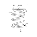
- FIG. 1 is a front view of a suspension coil spring according to an embodiment of the present invention.
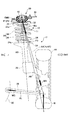
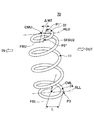
- FIG. 2 is a side view showing a configuration of a strut type suspension device to which a suspension coil spring according to an embodiment of the present invention is assembled.
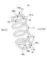
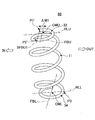
- FIG. 3 is a perspective view of a suspension coil spring according to an embodiment of the present invention.
- FIG. 4 is a diagram for explaining the shape of the spring effective portion of the suspension coil spring according to the embodiment of the present invention.
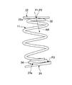
- FIG. 5A is a diagram for explaining the operation of the suspension coil spring according to the embodiment of the present invention.
- FIG. 5B is a diagram for explaining the operation of the suspension coil spring according to the embodiment of the present invention.
- FIG. 5C is a diagram for explaining the operation of the suspension coil spring according to the embodiment of the present invention.
- FIG. 6 is a perspective view showing a first modification of the suspension coil spring according to the embodiment of the present invention.
- FIG. 7 is a perspective view showing a second modification of the suspension coil spring according to the embodiment of the present invention.
- FIG. 1 and 3 are views illustrating a suspension coil spring 10 according to an embodiment of the present invention.
- FIG. 2 is a diagram illustrating a strut type suspension device 12 (hereinafter simply referred to as a suspension device 12) in which the suspension coil spring 10 is assembled.
- a portion excluding the support portion at the upper end of the suspension coil spring 10 is indicated by a two-dot chain line.
- the IN direction of the white arrow indicates the vehicle body side
- the OUT direction indicates the vehicle exterior side.
- the suspension device 12 includes a shock absorber 14 as a strut for positioning the wheel 44.
- the shock absorber 14 includes a cylinder 16 in which a fluid such as gas or oil is sealed, and a rod 18 that is connected to a piston (not shown) slidably disposed in the cylinder 16 and protrudes upward from the cylinder 16. It has.
- the upper end of the rod 18 is elastically connected to the vehicle body 30 of the automobile via the strut mount 20.
- An upper seat 22 is disposed on the upper end side of the rod 18, and a lower seat 24 is disposed on the middle portion of the cylinder 16.
- the suspension coil spring 10 is disposed in a compressed state between the upper seat 22 and the lower seat 24 at the outer peripheral position of the shock absorber 14. As a result, a spring reaction force WR is generated in the suspended coil spring 10 in the mounted state.
- the axis on which the spring reaction force WR acts is referred to as a spring reaction force axis AR.
- the lower end of the shock absorber 14 is rigidly connected to a knuckle 26 that supports the wheel 44 in a rotatable manner.
- the knuckle 26 is pivotally coupled to the vehicle body 30 via the lower arm 28.
- the wheel 44 that is pivotally supported by the knuckle 26 supports the vehicle body 30 via the shock absorber 14 and the suspension coil spring 10, and supports the vehicle body 30 via the lower arm 28.
- FIG. 1 is a front view illustrating a suspension coil spring 10 in a free state.
- the suspension coil spring 10 an upper end winding portion 32 that is seated on the upper seat 22 is formed above the spring effective portion 11, and a lower end winding portion 34 that is seated on the lower seat 24 is formed below.
- the suspension coil spring 10 is configured so that the outline m of the spring effective portion 11 is in a straight line in a free state in which no load is applied, but is not limited thereto. Further, in the free state, the front view outer diameter D of the portion of the coil other than the upper end winding portion 32, the lower end winding portion 34 and the transition portion to each end winding portion of the spring effective portion 11 is a constant size. Although formed, it is not limited to this.
- the suspension coil spring 10 is mounted on the suspension device 12 in a compressed state with the upper end winding portion 32 seated on the upper seat 22 and the lower end winding portion 34 seated on the lower seat 24.
- the upper seat 22 and the lower seat 24 of the suspension device 12 are formed in a substantially disc shape, and rib-shaped mounting portions 22 a and 24 a are formed at the respective central positions.
- the upper end winding portion 32 of the suspension coil spring 10 is mounted on the upper seat 22 such that the mounting portion 22a is inserted therein.
- the lower end winding part 34 is attached to the lower seat 24 so that the attachment part 24a is inserted therein. With this configuration, the suspension coil spring 10 is positioned between the upper seat 22 and the lower seat 24.
- the center position of the upper end winding portion 32 is referred to as an upper end winding center point CMU, and the center position of the lower end winding portion 34 is referred to as a lower end winding center point CML (see FIG. 3).
- a line segment that passes through the upper end winding center point CMU and extends in the longitudinal direction of the vehicle body is referred to as an upper longitudinal direction line FBU, and a line segment that passes through the upper end winding center point CMU and extends in the vehicle body left and right direction. This is referred to as the upper left / right direction line RLU.
- a line segment that passes through the lower end winding center point CML and extends in the longitudinal direction of the vehicle body is referred to as a lower longitudinal direction line FBL, and passes through the lower end winding center point CML and extends in the lateral direction of the vehicle body.
- This line segment is referred to as a lower left / right direction line RLL.
- the lower seat 24 and the lower end winding portion 34 are located on the lower end winding portion 34 on the vehicle outer side from the center point CML of the lower end winding portion 34. It forms so that it may contact substantially in the lower contact point P3 of a location.
- the fact that the lower seat 24 and the lower end winding part 34 substantially contact at one lower contact point P3 means a position other than the lower contact point P3 of the lower end winding part 34 (hereinafter referred to as the lower contact point P3). Even if the position other than P3 is in contact with the lower seat 24, the load acting on the position other than P3 is smaller than the load acting on the lower contact point P3.
- the lower end winding portion 34 has a reverse pitch that forms an angle ⁇ with respect to a direction orthogonal to the outline m of the spring effective portion 11 (the spring element wire is wound so that the pitch decreases). To be done). Further, as shown in FIG. 3, the lower contact portion P3 is provided at a position on the lower left-right direction line RLL and at a distance L from the lower end winding center point CML to the vehicle outer side.
- the number of turns of the upper end winding portion 32 is 0.5 (180 ° winding) and is bent at a portion connected to the spring effective portion 11, and FIG. 1 and FIG.
- the upper end winding portion 32 has a substantially semicircular arc shape and is configured to be positioned on the vehicle outer side with respect to the upper front-rear direction line FBU. Further, the upper contact portions P1, P2 of the upper end winding portion 32 are provided on the upper front-rear direction line FBU and spaced apart from each other by 180 °, and a line segment connecting the upper contact portions P1, P2 and the upper front-rear direction line The FBU is configured to overlap.
- the upper contact portion P ⁇ b> 1 of the upper end winding portion 32 is an end portion of a spring wire constituting the suspension coil spring 10.
- the upper contact portion P2 is a portion connected to the spring effective portion 11 at a position of 0.5 turns from the upper contact portion P1 (a position wound 180 ° from the upper contact portion P1).
- the upper end winding part 32 is configured to be substantially symmetric with respect to the upper left-right direction line RLU.
- the upper contact portions P ⁇ b> 1 and P ⁇ b> 2 substantially contact the upper seat 22 more strongly than other portions of the upper end winding portion 32, and the suspension device 12. It is attached to.
- the upper contact portions P1 and P2 are located on the upper front-rear direction line FBU, and the substantially center position between the upper contact portion P1 and the upper contact portion P2 is the upper end winding. It becomes the center point CMU.
- the upper seat 22 and the upper end winding portion 32 substantially contact only at the two upper contact points P1 and P2, and the positions other than the upper contact points P1 and P2 of the upper end winding portion 32 (hereinafter referred to as “the upper end winding portion 32”). Even if the position other than P1 and P2 is in contact with the upper seat 22, the load acting on the position other than P1 and P2 is smaller than the load acting on the upper contact points P1 and P2.
- AS is a strut shaft that is the central axis of the shock absorber 14
- AK is a kingpin axis that is the steering central axis of the wheel 44
- AL is a lower arm axis that is the central axis of the lower arm 28
- AA is the shock absorber 14 from the road surface. It is a load input shaft.
- a road surface reaction force W from the road surface acts on the suspension device 12 in the vertical direction from the center position of the contact surface of the wheel 44. Furthermore, the load axial force WU that opposes the road surface reaction force W acts on the suspension device 12 from the upper end of the shock absorber 14 along the load input axis AA.
- a lower arm axial force WC which is a combined force of the road surface reaction force W and the load axial force WU, acts on the root portion of the lower arm 28 along the lower arm axis AL.
- the load acting on the position other than P3 at the time of this contact is smaller than the load acting on the lower contact point P3. Therefore, even when a position other than P3 is in contact with the lower seat 24, the spring reaction force WR mainly acts on the lower contact point P3 or a position close thereto.
- the lower contact point P3 where the lower seat 24 and the lower end winding portion 34 substantially contact or its proximity point is the lower working point of the spring reaction force WR.
- the lower acting point of the spring reaction force WR can be moved by adjusting the angle ⁇ of the lower end winding portion 34 and the spring reaction force axis AR and the load input axis AA are substantially coincident (AR ⁇ AA). In the position. With such a configuration, it is possible to cancel the load axial force WU with the spring reaction force WR, avoid the occurrence of a lateral force in the shock absorber 14, and suppress the occurrence of friction.
- the substantially center position of the upper contact portions P1, P2 is the upper end winding center point CMU, and the upper end winding portion 32 is substantially the same as the upper seat 22. Since the contact is made at a point, the upper end winding portion 32 is configured to be swingable with respect to the upper seat 22 about the upper front-rear direction line FBU connecting the upper contact points P1, P2.
- the upper acting point of the spring reaction force WR is located at the substantially upper end winding center point CMU and does not deviate from this position.
- the suspension coil spring 10 When the suspension coil spring 10 is mounted on the suspension device 12, the suspension coil spring 10 is displaced with respect to the upper seat 22 by inputting the road surface reaction force W from the road surface via the wheels 44 to the suspension device 12 ( FIG. 5A to FIG. 5C). At this time, the upper end winding part 32 swings about the upper front-rear direction line FBU connecting the upper contact points P1 and P2, so that in addition to the upper contact points P1 and P2, the positions other than P1 and P2 and the upper seat 22 It is possible to come into contact.
- the load acting on the positions other than P1 and P2 at the time of this contact is smaller than the load acting on the upper contact points P1 and P2. Therefore, even if a position other than P1 and P2 contacts the upper seat 22, the spring reaction force WR mainly acts on the center position of the upper contact points P1 and P2, that is, the position of the upper end winding center point CMU. Therefore, a substantially uniform load is applied to the bearing portion 42 of the strut mount 20, and the mount is prevented from being twisted.
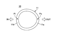
- FIG. 4 is a diagram for explaining the shape of the spring effective portion 11 of the suspension coil spring 10 according to the present embodiment.
- the spring effective portion 11 has a first spring portion 11a on the vehicle outer side and a second spring portion 11b on the vehicle body side.
- the first spring portion 11a and the second spring portion 11b are alternately formed approximately every half turn (0.5 turns).
- the curvature at Po located on the outermost side of the first spring part 11a is the other position of the first spring part 11a, all the positions of the second spring part 11b, and the first spring part 11a and the second spring part. 11b is formed so as to be larger than the curvature at all positions of the portion connecting with 11b.
- the curvature of the first spring portion 11a at Po is larger than the curvature of Pi at the most vehicle body side of the second spring portion 11b.
- the first spring portion 11a and the second spring portion 11b, each having a gradually changing curvature, are smoothly connected to each other, and the spring effective portion 11 is formed in a substantially egg shape when viewed from above.
- the shape of the spring effective portion 11 is obtained based on, for example, a curvature change calculation formula represented by the following formula (1).
- H is the coil radius in the longitudinal direction of the vehicle body
- W is the coil radius in the lateral direction of the vehicle body.
- the shape of the spring effective portion 11 is formed on the basis of a combination of shapes changed by using W, H, and a as variables.
- the spring effective portion 11 when the spring effective portion 11 is formed in a perfect circle shape in a top view, in addition to being a strut type suspension device, the lower contact portion P3 is biased toward the vehicle exterior, so that the compressed state In this case, the amount of torsion that the vehicle body side protrudes becomes larger. If the amount of bending of the suspension coil spring 10 is large, the direction of action of the spring reaction force WR deviates from the load input axis AA, and friction is generated in the shock absorber 14, preventing the smooth operation of the shock absorber 14 and riding comfort of the automobile. Will get worse. Moreover, if the amount of torsion is large, the stress increase location will generate
- the suspension coil spring 10 has the above-described shape, thereby reducing the amount of bending of the spring effective portion 11 toward the vehicle body in the compressed state. Therefore, the friction generated in the shock absorber 14 is reduced, and the riding comfort of the automobile is kept comfortable. In addition, in the compressed state, a local stress increase portion does not occur in the spring effective portion 11, and the suspension coil spring 10 can be used for a long time.
- FIG. 5A to 5C are diagrams illustrating the state of the suspension coil spring 10 when road surface reaction forces W of different magnitudes are input from the wheels 44.
- FIG. FIG. 5A shows a case where a road surface reaction force W A
- FIG. 5B shows a road surface reaction force W B (> W A )
- FIG. 5C shows a case where a road surface reaction force W C (> W B ) is inputted.
- the suspension coil spring 10 is deformed according to the change in the road surface reaction force W, but the amount of torsion during compression is reduced.
- the suspension coil spring 10 When the road surface reaction force W changes, the suspension coil spring 10 is deformed according to the magnitude of the road surface reaction force W. With the deformation of the suspension coil spring 10, the contact states of the lower end winding portion 34 with respect to the lower seat 24 and the upper end winding portion 32 with respect to the upper seat 22 change.
- the lower seat 24 and the lower end winding portion 34 are provided at a position below the one provided on the lower end winding portion 34. It is comprised so that it may contact substantially in the side contact point P3. As a result, the lower end winding part 34 also comes into strong contact with the lower side seat 24 at the lower contact point P3, and even if the suspension coil spring 10 is deformed according to the magnitude of the road surface reaction force W, the lower left-right direction line RLL A position that is above and separated from the lower end winding center point CML toward the vehicle outer side is maintained.
- the upper seat winding portion 32 and the upper seat 22 are in strong contact with each other at the upper contact points P1 and P2, so the upper seat 22 is connected to the upper front-rear direction line connecting the upper contact point P1 and the upper contact point P2. Swings around the FBU. For this reason, even if the suspension coil spring 10 is deformed according to the magnitude of the road surface reaction force W, the upper front-rear direction line FBU always maintains a position passing through the upper end winding center point CMU.
- FIGS. 1 to 5C are views showing suspension coil springs 60 and 70, which are modifications of the suspension coil spring 10, respectively. 6 and 7, the components corresponding to the configuration of the suspension coil spring 10 illustrated in FIGS. 1 to 5C are denoted by the same reference numerals and description thereof is omitted.
- the suspension coil spring 60 of the modification shown in FIG. 6 has the upper end winding portion 32 formed in about 0.6 turns.
- the suspension coil spring 60 is configured such that the upper front-rear direction line SFBU1, which is a line segment connecting the upper contact points P1 ', P2', and the upper front-rear direction line FBU are parallel to each other.
- the upper end winding portion 32 having approximately 0.6 turns is formed so as to be substantially symmetric with respect to the upper left-right direction line RLU.
- the upper front-rear direction line SFBU1 is formed so as to be separated from the upper end winding center point CMU by a dimension indicated by an arrow ⁇ M1 in the vehicle body side direction from the upper end winding center point CMU.
- the suspension coil spring 70 of the modification shown in FIG. 7 has the upper end winding portion 32 formed in about 0.4 turns.
- the suspension coil spring 70 is configured such that the upper front-rear direction line SFBU2, which is a line segment connecting the upper contact points P1 ", P2", and the upper front-rear direction line FBU are parallel to each other.
- the upper end winding portion 32 having about 0.4 turns is formed so as to be substantially symmetric with respect to the upper left-right direction line RLU.
- the upper front-rear direction line SFBU2 is formed so as to be separated from the upper end winding center point CMU by a dimension indicated by an arrow ⁇ M2 in the drawing in the vehicle outer side direction from the upper end winding center point CMU.
- the upper contact points P1, P2 are the upper end winding center point CMU.
- the amount of separation from the bearing becomes larger, the friction at the sliding portion of the shock absorber 14 increases, and the load (spring reaction force) acts on the bearing portion of the strut mount 20 to increase the possibility that the mount will be twisted. .
- the suspension coil spring 10 can be used in a compressed state even when the coil outer diameter is reduced or the size is reduced by reducing the number of turns. The amount of bending is reduced.
- the suspension device 12 including the suspension coil spring 10 can reduce the generation of friction in the shock absorber 14, suppress the strut mount 20 from being twisted, and can comfortably maintain the riding comfort of the automobile.
- the lower end winding portion 34 is set to a reverse pitch, whereby the lower end winding portion 34 comes into substantial contact with the lower seat 24 substantially at one point, so that the spring reaction force axis AR is inclined. It has a configuration.
- the spring reaction force axis AR may be inclined by making the lower end winding portion flat and forming an inclined portion on the lower seat.
- the said embodiment it was set as the structure which the upper part winding part 32 and the upper part seat 22 contact strongly at two points (upper contact part P1, P2) by making the upper part winding part 32 into 0.5 turns.
- the projection may be formed at a position corresponding to the upper contact portions P1 and P2 of the upper end winding portion 32 or the upper seat 22.
- Suspension coil spring 11 Spring effective portion 11a First spring portion 11b Second spring portion 12 Suspension device 14 Shock absorber 20 Strut mount 22 Upper seat 24 Lower seat 30 Vehicle body 32 Upper seat winding portion 34 Lower seat winding Part 42 Bearing 44 Wheel AA Load input axis AL Lower arm axis AR Spring reaction axis AS Strut axis CA Coil axis CMU Upper end winding center point CML Lower end winding center point FBU Upper front / rear direction line FBL Lower front / rear direction line FBM Front / rear Direction line m Outline line RLU Upper left / right direction line RLL Lower left / right direction line RLM Left / right direction line SFBU1. SFBU2 Upper front-rear direction line W Road surface reaction force WU Load axial force WC Lower arm axial force WR Spring reaction force P1, P2 Upper contact portion P3 Lower contact portion
Landscapes
- Engineering & Computer Science (AREA)
- General Engineering & Computer Science (AREA)
- Mechanical Engineering (AREA)
- Springs (AREA)
- Vehicle Body Suspensions (AREA)
- Fluid-Damping Devices (AREA)
Abstract
Description
自動車用のストラット型懸架装置における上側座と下側座との間に装着される懸架コイルばねであって、
前記上側座に着座する上側座巻と、
装着状態において、曲率の最も大きい部位が車外側に位置するように形成された巻きを1つ以上有するばね有効部と、
下側座巻中心点より車外側に位置する一箇所の下側接触点で前記下側座に接触して着座する下側座巻と、を有する
ことを特徴とする懸架コイルばねによって解決される。
Hは車体前後方向のコイル半径であり、Wは車体左右方向のコイル半径である。ばね有効部11形状は、W,H,aを変数として変化させた形状の組み合わせをベースに形成される。
11 ばね有効部
11a 第1ばね部
11b 第2ばね部
12 懸架装置
14 ショックアブソーバ
20 ストラットマウント
22 上側座
24 下側座
30 車体
32 上側座巻部
34 下側座巻部
42 軸受部
44 車輪
AA 荷重入力軸
AL ロアーアーム軸
AR ばね反力軸
AS ストラット軸
CA コイル軸
CMU 上側座巻中心点
CML 下側座巻中心点
FBU 上側前後方向線
FBL 下側前後方向線
FBM 前後方向線
m 外形線
RLU 上側左右方向線
RLL 下側左右方向線
RLM 左右方向線
SFBU1.SFBU2 上側前後方向線
W 路面反力
WU 荷重軸線力
WC ロアーアーム軸力
WR ばね反力
P1,P2 上側接触部
P3 下側接触部
Claims (4)
- 自動車用のストラット型懸架装置における上側座と下側座との間に装着される懸架コイルばねであって、
前記上側座に着座する上側座巻と、
装着状態において、曲率の最も大きい部位が車外側に位置するように形成された巻きを1つ以上有するばね有効部と、
下側座巻中心点より車外側に位置する一箇所の下側接触点で実質的に前記下側座に接触して着座する下側座巻と、を有する
ことを特徴とする懸架コイルばね。 - 前記上側座巻は、上側座巻中心点を通り前記自動車の左右方向に延在する線分に対して略対称に設けられており、前記自動車の前後方向に離間して設けられた二箇所の上側接触点で実質的に前記上側座に接触して着座する
ことを特徴とする請求項1に記載の懸架コイルばね。 - 前記上側座巻は、0.4巻以上0.6巻以下であり、前記二箇所の上側接触点が、前記自動車の前後方向に延在する線分に平行な線分上に形成されている
ことを特徴とする請求項2に記載の懸架コイルばね。 - 前記下側座巻は、逆ピッチに形成されている
ことを特徴とする請求項1に記載の懸架コイルばね。
Priority Applications (9)
| Application Number | Priority Date | Filing Date | Title |
|---|---|---|---|
| ES15798841T ES2849601T3 (es) | 2014-05-28 | 2015-05-25 | Resorte helicoidal de suspensión |
| BR112016026700-1A BR112016026700B1 (pt) | 2014-05-28 | 2015-05-25 | Mola helicoidal de suspensão |
| MX2016014430A MX2016014430A (es) | 2014-05-28 | 2015-05-25 | Resorte helicoidal para suspension. |
| CN201580025118.2A CN106457947B (zh) | 2014-05-28 | 2015-05-25 | 悬架螺旋弹簧 |
| EP15798841.1A EP3127727B1 (en) | 2014-05-28 | 2015-05-25 | Suspension coil spring |
| US15/307,083 US10300756B2 (en) | 2014-05-28 | 2015-05-25 | Suspension coil spring |
| KR1020187016169A KR20180066277A (ko) | 2014-05-28 | 2015-05-25 | 현가 코일 스프링 |
| KR1020167029571A KR102059115B1 (ko) | 2014-05-28 | 2015-05-25 | 현가 코일 스프링 |
| CA2946377A CA2946377C (en) | 2014-05-28 | 2015-05-25 | Suspension coil spring |
Applications Claiming Priority (2)
| Application Number | Priority Date | Filing Date | Title |
|---|---|---|---|
| JP2014-109767 | 2014-05-28 | ||
| JP2014109767A JP5981958B2 (ja) | 2014-05-28 | 2014-05-28 | 懸架コイルばね及びストラット型懸架装置 |
Publications (1)
| Publication Number | Publication Date |
|---|---|
| WO2015182543A1 true WO2015182543A1 (ja) | 2015-12-03 |
Family
ID=54698872
Family Applications (1)
| Application Number | Title | Priority Date | Filing Date |
|---|---|---|---|
| PCT/JP2015/064882 WO2015182543A1 (ja) | 2014-05-28 | 2015-05-25 | 懸架コイルばね |
Country Status (10)
| Country | Link |
|---|---|
| US (1) | US10300756B2 (ja) |
| EP (1) | EP3127727B1 (ja) |
| JP (1) | JP5981958B2 (ja) |
| KR (2) | KR102059115B1 (ja) |
| CN (1) | CN106457947B (ja) |
| BR (1) | BR112016026700B1 (ja) |
| CA (1) | CA2946377C (ja) |
| ES (1) | ES2849601T3 (ja) |
| MX (1) | MX2016014430A (ja) |
| WO (1) | WO2015182543A1 (ja) |
Families Citing this family (3)
| Publication number | Priority date | Publication date | Assignee | Title |
|---|---|---|---|---|
| JP6613095B2 (ja) | 2015-10-01 | 2019-11-27 | 日本発條株式会社 | 懸架用コイルばね |
| US10598242B2 (en) * | 2016-05-20 | 2020-03-24 | Sealy Technology, Llc | Coil springs with non-linear loading responses and mattresses including the same |
| DE102018220235A1 (de) * | 2018-11-26 | 2020-05-28 | Ford Global Technologies, Llc | Einzelradaufhängung für ein Kraftfahrzeug |
Citations (3)
| Publication number | Priority date | Publication date | Assignee | Title |
|---|---|---|---|---|
| JPS6095311U (ja) * | 1983-12-08 | 1985-06-28 | 日産自動車株式会社 | ストラツト式懸架装置 |
| JPH0249703U (ja) * | 1988-09-30 | 1990-04-06 | ||
| JP2000104772A (ja) * | 1998-07-31 | 2000-04-11 | Chuo Spring Co Ltd | 自動車用懸架コイルばね |
Family Cites Families (29)
| Publication number | Priority date | Publication date | Assignee | Title |
|---|---|---|---|---|
| JPS5832970A (ja) | 1981-08-19 | 1983-02-26 | Mitsubishi Electric Corp | 配電器の取付装置 |
| JPS5832970U (ja) | 1981-08-25 | 1983-03-03 | 泰東製綱株式会社 | オツタ−ボ−ド |
| JPS59190528A (ja) * | 1983-04-12 | 1984-10-29 | Mitsubishi Motors Corp | 異形断面つる巻きバネ |
| JPS60237235A (ja) * | 1984-05-10 | 1985-11-26 | Chuo Spring Co Ltd | コイルばね |
| JPS60241535A (ja) * | 1984-05-12 | 1985-11-30 | Sanko Senzai Kogyo Kk | コイルばね |
| JPS61167728A (ja) * | 1985-01-18 | 1986-07-29 | Murata Hatsujo Kk | コイルばね |
| DE3743450A1 (de) | 1987-12-08 | 1989-06-29 | Muhr & Bender | Radaufhaengung |
| FR2678035B1 (fr) * | 1991-06-20 | 1995-04-14 | Valeo | Ressort a boudin, notamment pour amortisseur de torsion. |
| DE4203658C2 (de) * | 1992-02-08 | 1995-07-13 | Bayerische Motoren Werke Ag | Schraubenfederabstützung, insbesondere an einem Fahrzeugfederbein |
| FR2730673B1 (fr) * | 1995-02-17 | 1997-05-09 | Allevard Sa | Dispositif de suspension du type mac pherson pour vehicule |
| FR2742830B1 (fr) * | 1995-12-21 | 1999-04-16 | Ace Engineering | Ressort helicoidal notamment pour suspension de vehicules automobiles |
| JPH1156119A (ja) | 1997-08-25 | 1999-03-02 | Kazuo Yoshitake | 温室カーテン開閉装置 |
| JP4601108B2 (ja) * | 2000-01-28 | 2010-12-22 | 中央発條株式会社 | 湾曲コイルばね及び該湾曲コイルばねの製造方法 |
| JP2002178736A (ja) * | 2000-12-14 | 2002-06-26 | Chuo Spring Co Ltd | 自動車用懸架コイルばね及び該懸架コイルばねを備えたストラット型懸架装置 |
| US6481701B2 (en) * | 2001-03-09 | 2002-11-19 | Delphi Technologies, Inc. | Spring having coils of varying diameters |
| US20020190452A1 (en) * | 2001-06-19 | 2002-12-19 | Barry Drager | Coil spring having non-circular coils |
| US20050051937A1 (en) * | 2001-11-27 | 2005-03-10 | Masahiro Umezawa | Compression coil spring device having discontinuous support structure |
| JP4212311B2 (ja) * | 2002-07-17 | 2009-01-21 | 中央発條株式会社 | 懸架コイルばね |
| US20040169324A1 (en) * | 2003-02-28 | 2004-09-02 | Bottene Marlon V. | Strut spring seat |
| FR2860752B1 (fr) * | 2003-10-09 | 2006-03-17 | Allevard Rejna Autosuspensions | Suspension de vehicule a raideur variable |
| FR2860753B1 (fr) * | 2003-10-09 | 2007-07-27 | Allevard Rejna Autosuspensions | Suspension de vehicule |
| JP2005226673A (ja) * | 2004-02-10 | 2005-08-25 | Nhk Spring Co Ltd | コイルばね及び懸架装置 |
| JP4862561B2 (ja) * | 2006-08-30 | 2012-01-25 | マツダ株式会社 | サスペンション装置のコイルスプリング取付構造 |
| EP1935678A3 (de) * | 2006-12-18 | 2010-04-14 | Muhr und Bender KG | Radaufhängung |
| JP5268261B2 (ja) * | 2007-01-26 | 2013-08-21 | 日本発條株式会社 | コイルばね |
| CN102016344B (zh) * | 2008-05-07 | 2012-09-05 | 株式会社东乡制作所 | 异形截面螺旋弹簧 |
| US8061696B2 (en) * | 2008-09-18 | 2011-11-22 | Yang Min Enterprise Corporation | Shock-absorbing spring for vehicles |
| JP5313210B2 (ja) * | 2010-06-30 | 2013-10-09 | 三菱製鋼株式会社 | コイルばね |
| DE202013002175U1 (de) * | 2013-03-07 | 2013-03-15 | Audi Ag | Schraubenfeder |
-
2014
- 2014-05-28 JP JP2014109767A patent/JP5981958B2/ja active Active
-
2015
- 2015-05-25 WO PCT/JP2015/064882 patent/WO2015182543A1/ja active Application Filing
- 2015-05-25 MX MX2016014430A patent/MX2016014430A/es unknown
- 2015-05-25 CN CN201580025118.2A patent/CN106457947B/zh active Active
- 2015-05-25 US US15/307,083 patent/US10300756B2/en active Active
- 2015-05-25 ES ES15798841T patent/ES2849601T3/es active Active
- 2015-05-25 BR BR112016026700-1A patent/BR112016026700B1/pt active IP Right Grant
- 2015-05-25 EP EP15798841.1A patent/EP3127727B1/en active Active
- 2015-05-25 CA CA2946377A patent/CA2946377C/en active Active
- 2015-05-25 KR KR1020167029571A patent/KR102059115B1/ko active IP Right Grant
- 2015-05-25 KR KR1020187016169A patent/KR20180066277A/ko active Application Filing
Patent Citations (3)
| Publication number | Priority date | Publication date | Assignee | Title |
|---|---|---|---|---|
| JPS6095311U (ja) * | 1983-12-08 | 1985-06-28 | 日産自動車株式会社 | ストラツト式懸架装置 |
| JPH0249703U (ja) * | 1988-09-30 | 1990-04-06 | ||
| JP2000104772A (ja) * | 1998-07-31 | 2000-04-11 | Chuo Spring Co Ltd | 自動車用懸架コイルばね |
Non-Patent Citations (1)
| Title |
|---|
| See also references of EP3127727A4 * |
Also Published As
| Publication number | Publication date |
|---|---|
| JP2015231751A (ja) | 2015-12-24 |
| BR112016026700A2 (pt) | 2017-08-15 |
| CA2946377C (en) | 2018-06-12 |
| KR102059115B1 (ko) | 2019-12-24 |
| ES2849601T3 (es) | 2021-08-19 |
| US10300756B2 (en) | 2019-05-28 |
| EP3127727A4 (en) | 2017-04-19 |
| JP5981958B2 (ja) | 2016-08-31 |
| CA2946377A1 (en) | 2015-12-03 |
| CN106457947A (zh) | 2017-02-22 |
| CN106457947B (zh) | 2019-11-01 |
| KR20160138192A (ko) | 2016-12-02 |
| EP3127727A1 (en) | 2017-02-08 |
| MX2016014430A (es) | 2017-02-23 |
| EP3127727B1 (en) | 2020-12-09 |
| BR112016026700A8 (pt) | 2021-06-22 |
| BR112016026700B1 (pt) | 2022-08-16 |
| US20170050486A1 (en) | 2017-02-23 |
| KR20180066277A (ko) | 2018-06-18 |
Similar Documents
| Publication | Publication Date | Title |
|---|---|---|
| JP5873891B2 (ja) | 懸架コイルばね及びストラット型懸架装置 | |
| JP5293770B2 (ja) | サスペンション構造、サスペンションリンク配置方法 | |
| US20110248465A1 (en) | Rear wheel suspension, the coil spring of which has a tilted line of action of force | |
| US10688843B2 (en) | Vehicle torsion beam suspension and vehicle torsion beam | |
| WO2015182543A1 (ja) | 懸架コイルばね | |
| JP2016047722A (ja) | 懸架コイルばね及びストラット型懸架装置 | |
| JP2008056002A (ja) | サスペンション装置のコイルスプリング取付構造 | |
| JP2005226673A (ja) | コイルばね及び懸架装置 | |
| JP4211667B2 (ja) | トーションビーム式サスペンション装置 | |
| JP6348766B2 (ja) | 車両用サスペンション | |
| JP2010260513A (ja) | サスペンションアーム | |
| JP6497343B2 (ja) | 車両のサスペンション構造 | |
| JP2006248256A (ja) | トレーリングアーム構造 | |
| JP2008201306A (ja) | スタビライザ装置 | |
| JP5326528B2 (ja) | ダブル・ジョイント式サスペンション | |
| JP2010047041A (ja) | サスペンション用ブッシュ | |
| JP2007168753A (ja) | ストラット式サスペンション装置 | |
| JP2006143001A (ja) | アクスルブラケットおよびそれを用いたサスペンション装置 | |
| KR20090119290A (ko) | 차량용 스테빌라이저 바 | |
| JP2008114696A (ja) | スタビライザ連結構造 | |
| KR20080006198A (ko) | 자동차의 전륜 현가장치 | |
| JP2010090960A (ja) | ブッシュ | |
| JP2010247672A (ja) | 車両用サスペンション |
Legal Events
| Date | Code | Title | Description |
|---|---|---|---|
| 121 | Ep: the epo has been informed by wipo that ep was designated in this application |
Ref document number: 15798841 Country of ref document: EP Kind code of ref document: A1 |
|
| ENP | Entry into the national phase |
Ref document number: 2946377 Country of ref document: CA |
|
| REEP | Request for entry into the european phase |
Ref document number: 2015798841 Country of ref document: EP |
|
| WWE | Wipo information: entry into national phase |
Ref document number: 2015798841 Country of ref document: EP |
|
| ENP | Entry into the national phase |
Ref document number: 20167029571 Country of ref document: KR Kind code of ref document: A |
|
| WWE | Wipo information: entry into national phase |
Ref document number: 15307083 Country of ref document: US |
|
| WWE | Wipo information: entry into national phase |
Ref document number: MX/A/2016/014430 Country of ref document: MX |
|
| WWE | Wipo information: entry into national phase |
Ref document number: IDP00201608096 Country of ref document: ID |
|
| NENP | Non-entry into the national phase |
Ref country code: DE |
|
| REG | Reference to national code |
Ref country code: BR Ref legal event code: B01A Ref document number: 112016026700 Country of ref document: BR |
|
| ENP | Entry into the national phase |
Ref document number: 112016026700 Country of ref document: BR Kind code of ref document: A2 Effective date: 20161114 |