WO2015182196A1 - 空気調和機、および空気調和機の制御方法 - Google Patents
空気調和機、および空気調和機の制御方法 Download PDFInfo
- Publication number
- WO2015182196A1 WO2015182196A1 PCT/JP2015/055812 JP2015055812W WO2015182196A1 WO 2015182196 A1 WO2015182196 A1 WO 2015182196A1 JP 2015055812 W JP2015055812 W JP 2015055812W WO 2015182196 A1 WO2015182196 A1 WO 2015182196A1
- Authority
- WO
- WIPO (PCT)
- Prior art keywords
- expansion valve
- opening
- opening degree
- processor
- defrosting operation
- Prior art date
- Legal status (The legal status is an assumption and is not a legal conclusion. Google has not performed a legal analysis and makes no representation as to the accuracy of the status listed.)
- Ceased
Links
Images






Classifications
-
- F—MECHANICAL ENGINEERING; LIGHTING; HEATING; WEAPONS; BLASTING
- F25—REFRIGERATION OR COOLING; COMBINED HEATING AND REFRIGERATION SYSTEMS; HEAT PUMP SYSTEMS; MANUFACTURE OR STORAGE OF ICE; LIQUEFACTION SOLIDIFICATION OF GASES
- F25B—REFRIGERATION MACHINES, PLANTS OR SYSTEMS; COMBINED HEATING AND REFRIGERATION SYSTEMS; HEAT PUMP SYSTEMS
- F25B13/00—Compression machines, plants or systems, with reversible cycle
-
- F—MECHANICAL ENGINEERING; LIGHTING; HEATING; WEAPONS; BLASTING
- F24—HEATING; RANGES; VENTILATING
- F24F—AIR-CONDITIONING; AIR-HUMIDIFICATION; VENTILATION; USE OF AIR CURRENTS FOR SCREENING
- F24F11/00—Control or safety arrangements
- F24F11/89—Arrangement or mounting of control or safety devices
-
- F—MECHANICAL ENGINEERING; LIGHTING; HEATING; WEAPONS; BLASTING
- F25—REFRIGERATION OR COOLING; COMBINED HEATING AND REFRIGERATION SYSTEMS; HEAT PUMP SYSTEMS; MANUFACTURE OR STORAGE OF ICE; LIQUEFACTION SOLIDIFICATION OF GASES
- F25B—REFRIGERATION MACHINES, PLANTS OR SYSTEMS; COMBINED HEATING AND REFRIGERATION SYSTEMS; HEAT PUMP SYSTEMS
- F25B1/00—Compression machines, plants or systems with non-reversible cycle
Definitions
- the present invention relates to a technology for an air conditioner, and more particularly to a technology for controlling an expansion valve of the air conditioner.
- an air conditioner has a refrigeration cycle in which components such as a compressor, a switching valve, an outdoor heat exchanger, an expansion valve that adjusts the flow rate of refrigerant when decompressing, an indoor heat exchanger, and the like are connected.
- the refrigeration cycle can be switched to either the cooling operation cycle or the heating operation cycle by switching the switching valve.
- the refrigerant circulates in the order of the compressor, the switching valve, the outdoor heat exchanger (condenser), the expansion valve, the indoor heat exchanger (evaporator), the switching valve, and the compressor.
- the indoor heat absorbed by the heat exchanger is released to the outside by the outdoor heat exchanger.
- the refrigerant circulates in the order of the compressor, the switching valve, the indoor heat exchanger (condenser), the expansion valve, the outdoor heat exchanger (evaporator), the switching valve, and the compressor.
- the outdoor heat absorbed by the heat exchanger is released indoors by the indoor heat exchanger.
- the degree of superheat is calculated by detecting the temperature of the evaporator and the outlet temperature of the evaporator, and the opening degree of the expansion valve is controlled using the degree of superheat.
- various methods are known for controlling an expansion valve of an air conditioner.
- Patent Document 1 discloses an air conditioner, an opening control method for an expansion valve, and a program.
- the air conditioner includes a first temperature sensor that detects a refrigerant temperature at the outlet of the compressor as a discharge temperature, and a condenser (1 or 3). And a second temperature sensor for detecting temperature.
- the control unit calculates the future predicted discharge temperature by extrapolating the compressor discharge temperatures detected at a plurality of times until now, and the temperature difference between the calculated predicted discharge temperature and the current temperature of the condenser Is calculated as the degree of superheat, and the opening degree of the expansion valve is set based on the calculated degree of superheat.
- JP 2002-349936 A discloses a method for controlling an air conditioner.
- Patent Document 2 in an air conditioner control method for controlling the opening / closing degree of an expansion valve constituting a refrigeration cycle, a frequency zone corresponding to the number of operations is determined, and an opening / closing degree table. The open / close degree according to the selected frequency zone is read, and the expansion valve is controlled to the read open / close degree. Then, the outside air temperature is detected, the zone corresponding to the outside air temperature is determined, and when the determined zone is the intermediate temperature Y zone, the current opening / closing degree of the expansion valve is maintained.
- Patent Document 3 discloses a heat pump type air conditioner.
- a heat pump having a refrigeration cycle in which refrigerant circulates in a closed circuit in which a compressor, a four-way valve, an indoor heat exchanger, a throttle mechanism, an outdoor heat exchanger, and the like are incorporated.
- an expansion valve manufactured for an air conditioner does not always have a constant flow rate.
- An object of the present invention is to provide an air conditioner, an air conditioner, and an air conditioner that can reduce the change in the opening degree of the expansion valve during heating operation more than before even when the flow rate of the expansion valve is larger or smaller than the standard. To provide a control method for a conditioner and a control program for an air conditioner.
- an air conditioner including an air conditioning mechanism including an expansion valve and a compressor and a control unit.
- the control unit determines a correction value based on the opening degree of the expansion valve immediately before the defrosting operation, and sets the opening degree of the expansion valve during the heating operation based on the correction value after the defrosting operation is completed.
- the control unit corrects the expansion valve so that the opening of the expansion valve during the heating operation after the completion of the defrosting operation increases as the opening of the expansion valve immediately before the defrosting operation is larger than the opening reference value.
- a control part determines a correction value so that the opening degree of the expansion valve at the time of heating operation after completion
- finish of a defrosting operation may be made small, so that the opening degree of the expansion valve immediately before a defrosting operation is smaller than an opening degree reference value. .
- the control unit opens the expansion valve during the heating operation after the defrosting operation when the opening degree of the expansion valve immediately before the defrosting operation is greater than the opening reference value by a first predetermined value or more.
- the correction value is determined so that the degree is increased by a second predetermined value from the opening degree reference value.
- the control unit opens the opening degree of the expansion valve during the heating operation after the completion of the defrosting operation.
- the correction value is determined so as to be smaller than the degree reference value by a fourth predetermined value.
- the second predetermined value is smaller than the first predetermined value.
- the fourth predetermined value is smaller than the third predetermined value.
- the control unit opens the expansion valve during the heating operation after the completion of the defrosting operation when the discharge temperature of the compressor immediately before the defrosting operation is higher than the discharge temperature reference value by a fifth predetermined value or more.
- the correction value is determined so that the degree is increased by a sixth predetermined value from the opening reference value.
- the controller opens the opening of the expansion valve during the heating operation after the defrosting operation as the discharge temperature of the compressor immediately before the defrosting operation is lower than the discharge temperature reference value by a seventh predetermined value or more.
- the correction value is determined to be smaller than the reference value by an eighth predetermined value.
- control unit stores a reference value.
- control unit uses the opening of the expansion valve immediately after any defrosting operation before the previous time as the opening reference value.
- a control method for an air conditioner including an air conditioning mechanism including an expansion valve and a compressor, and a control unit.
- the control method includes a step in which the control unit acquires the opening degree of the expansion valve immediately before the defrosting operation, a step in which the control unit determines a correction value from the opening degree of the expansion valve immediately before the defrosting operation, The step of causing the air conditioning mechanism to perform a defrosting operation, the step of setting the opening of the expansion valve during heating operation based on the correction value after the defrosting operation is completed, and the control unit And a step of causing the air-conditioning mechanism to perform a heating operation based on the set opening degree.
- a control program for an air conditioner including an air conditioning mechanism including an expansion valve and a compressor and a processor executes the step of obtaining the opening degree of the expansion valve immediately before the defrosting operation, the step of determining a correction value from the opening degree of the expansion valve immediately before the defrosting operation, and the defrosting operation to the air conditioning mechanism
- a step of setting the opening of the expansion valve during heating operation based on the correction value after the end of the defrosting operation, and a step of causing the air conditioning mechanism to perform the heating operation based on the set opening Are executed by the processor.
- an air conditioner an air conditioner control method, and a control program for the air conditioner are provided.
- the four-way selector valve is in the cooling operation state and the defrosting operation state.
- the four-way switching valve is in the heating operation state.
- FIG. 1 is a schematic configuration diagram of the air conditioner according to the first embodiment during the cooling operation and the defrosting operation.
- FIG. 2 is a schematic block diagram at the time of the heating operation of the air conditioner concerning 1st Embodiment.
- an air conditioner 1 is a separate type air conditioner, and mainly includes an outdoor unit 10, an indoor unit 30, and a remote controller 50. Yes.
- the air conditioner 1 is configured by connecting an indoor unit 30 and an outdoor unit 10 via refrigerant pipes 17 and 18.
- the outdoor unit 10, the indoor unit 30, the remote controller 50, and the refrigerant pipes 17 and 18 will be described in detail.
- Outdoor unit 10 mainly includes a housing 11, a compressor 12, a four-way switching valve 13, an outdoor heat exchanger 14, an expansion valve 15, an outdoor blower 16, a refrigerant pipe 17, a refrigerant pipe 18, It consists of a one-way valve 19, a three-way valve 20, an outdoor heat exchanger temperature sensor 21, a discharge temperature sensor 22, an intake temperature sensor 23, an outlet temperature sensor 24, an outdoor air temperature sensor 25, and an outdoor control unit 29.
- the outdoor unit 10 is installed outdoors.
- the casing 11 includes a compressor 12, a four-way switching valve 13, an outdoor heat exchanger 14, an expansion valve 15, an outdoor blower 16, a refrigerant pipe 17, a refrigerant pipe 18, a two-way valve 19, a three-way valve 20, and a temperature sensor 21. 25 and the outdoor control unit 29 and the like are accommodated.
- the compressor 12 has a discharge pipe 12a and a suction pipe 12b.
- the discharge pipe 12a and the suction pipe 12b are connected to different connection ports of the four-way switching valve 13, respectively.
- the compressor 12 is communicatively connected to the outdoor control unit 29 via a communication line, and operates according to a control signal transmitted from the outdoor control unit 29. During operation, the compressor 12 sucks low-pressure refrigerant gas from the suction pipe 12b, compresses the refrigerant gas to generate high-pressure refrigerant gas, and then discharges the high-pressure refrigerant gas from the discharge pipe 12a.
- the control format of the compressor 12 is not particularly limited, and may be a constant speed compressor or an inverter compressor.
- the four-way switching valve 13 is connected to the discharge pipe 12a and the suction pipe 12b of the compressor 12, the outdoor heat exchanger 14, and the indoor heat exchanger 32 via a refrigerant pipe.
- the four-way switching valve 13 is communicatively connected to the outdoor control unit 29 via a communication line, and operates according to a control signal transmitted from the outdoor control unit 29. Thereby, the four-way switching valve 13 connects the discharge pipe 12a of the compressor 12 to the outdoor heat exchanger 14 and connects the suction pipe 12b of the compressor 12 in accordance with a control signal transmitted from the outdoor control unit 29 during operation.
- the cooling operation state see FIG.
- the discharge pipe 12a of the compressor 12 is connected to the indoor heat exchanger 32
- the suction pipe 12b of the compressor 12 is connected to the outdoor heat exchanger 14.
- the heating operation state (see FIG. 2) to be switched is switched.
- the outdoor heat exchanger 14 has a plurality of heat radiating fins (not shown) attached to a heat transfer tube (not shown) bent back and forth at both left and right ends (fin and tube type), and is used during cooling operation. It functions as a condenser (see FIG. 1) and functions as an evaporator during heating operation (see FIG. 2). In addition, you may use a parallel flow type heat exchanger and a serpent type heat exchanger as a heat exchanger.
- the expansion valve 15 is an electronic expansion valve whose opening degree can be controlled via a stepping motor, which will be described later, and one is connected to the two-way valve 19 via the refrigerant pipe 17 and the other is the outdoor heat exchanger 14. It is connected to the.
- the stepping motor of the expansion valve 15 is communicatively connected to the outdoor control unit 29 via a communication line, and operates according to a control signal transmitted from the outdoor control unit 29.
- the expansion valve 15 reduces the pressure of the high-temperature and high-pressure liquid refrigerant flowing out of the condenser (the outdoor heat exchanger 14 at the time of cooling and the indoor heat exchanger 32 at the time of heating) to be easily evaporated during operation. At the same time, it plays the role of adjusting the amount of refrigerant supplied to the evaporator (the indoor heat exchanger 32 during cooling and the outdoor heat exchanger 14 during heating).
- the outdoor blower 16 is mainly composed of a propeller fan and a motor.
- the propeller fan is rotationally driven by a motor and supplies outdoor outdoor air to the outdoor heat exchanger 14.
- the motor is communicatively connected to the outdoor control unit 29 via a communication line, and operates according to a control signal transmitted from the outdoor control unit 29.
- the two-way valve 19 is disposed in the refrigerant pipe 17.
- the two-way valve 19 is closed when the refrigerant pipe 17 is removed from the outdoor unit 10 to prevent the refrigerant from leaking from the outdoor unit 10 to the outside.
- the three-way valve 20 is disposed in the refrigerant pipe 18.
- the three-way valve 20 is closed when the refrigerant pipe 18 is removed from the outdoor unit 10 to prevent the refrigerant from leaking from the outdoor unit 10 to the outside. Further, when it is necessary to recover the refrigerant from the outdoor unit 10 or from the entire refrigeration cycle including the indoor unit 30, the refrigerant is recovered through the three-way valve 20.
- the temperature sensors 21 to 25 are thermistors.
- the outdoor heat exchanger temperature sensor 21 is disposed in the outdoor heat exchanger 14, the discharge temperature sensor 22 is disposed in the discharge pipe 12 a of the compressor 12, and the suction temperature sensor 23 is disposed in the suction pipe 12 b of the compressor 12.
- the outlet temperature sensor 24 is arranged in the refrigerant pipe 17 in the vicinity of the outlet of the outdoor heat exchanger 14, and the outside air temperature sensor 25 is for measuring the outside air temperature and is arranged at a predetermined location inside the housing 11. Has been. All of these temperature sensors 21 to 25 are communicatively connected to the outdoor control unit 29 via communication lines, and transmit information on the measured temperature to the outdoor control unit 29.
- the outdoor control unit 29 is communicatively connected to the compressor 12, the four-way switching valve 13, the expansion valve 15, the outdoor blower 16, and the temperature sensors 21 to 25 via a communication line.
- the processor of the outdoor control unit 29 derives an appropriate control parameter by calculating the output information of the temperature sensors 21 to 25 and various control parameters stored in the memory at any time. It transmits to the compressor 12, the four-way switching valve 13, the expansion valve 15, and the outdoor blower 16. Further, the processor transmits and receives control parameters and the like to the indoor control unit 35 as necessary.
- the indoor unit 30 mainly includes a casing 31, an indoor heat exchanger 32, an indoor blower 33, a flap 36, an indoor heat exchanger temperature sensor 34, an indoor temperature sensor 37, and an indoor control unit 35. ing.
- the indoor unit 30 is generally installed on a wall surface in the room.
- the housing 31 houses an indoor heat exchanger 32, an indoor blower 33, an indoor heat exchanger temperature sensor 34, an indoor temperature sensor 37, an indoor control unit 35, and the like.
- the flap 36 constitutes a part of the housing 31.
- the indoor heat exchanger 32 is a combination of three heat exchangers 32A, 32B, and 32C like a roof that covers the indoor blower 33.
- Each of the heat exchangers 32A, 32B, and 32C has a plurality of radiating fins (not shown) attached to a heat transfer tube (not shown) that is bent back and forth at both left and right ends. It functions as an evaporator (see FIG. 1), and functions as a condenser during heating operation (see FIG. 2).
- the indoor blower 33 is mainly composed of a cross flow fan and a motor.
- the cross flow fan is rotationally driven by a motor, sucks indoor air into the casing 31 and supplies the air to the indoor heat exchanger 32, and sends out the air exchanged by the indoor heat exchanger 32 into the room.
- the motor is communicatively connected to the indoor control unit 35 via a communication line, and operates according to a control signal transmitted from the indoor control unit 35.
- the flap 36 includes a wind direction plate and a motor.
- the flap is rotated by a motor and adjusts the sending direction of the air sent into the room by the cross flow fan.
- the motor is communicatively connected to the indoor control unit 35 via a communication line, and operates according to a control signal transmitted from the indoor control unit 35.
- the temperature sensors 34 and 37 are thermistors.
- the indoor heat exchanger temperature sensor 34 is disposed in the indoor heat exchanger 32, and the indoor temperature sensor 37 measures the indoor temperature and is disposed in the vicinity of the suction port in the housing 31.
- the temperature sensors 34 and 37 are communicatively connected to the indoor control unit 35 via a communication line, and transmit information about the measured temperature to the indoor control unit 35.
- the indoor control unit 35 is communicatively connected to the indoor blower 33, the flap 36, and the temperature sensors 34 and 37 via a communication line.
- the processor of the indoor control unit 35 calculates the control signal from the remote controller 50, the output information of the temperature sensors 34 and 37, and the like as needed to derive appropriate control parameters. Or to the flap 36. Further, the processor transmits control parameters and the like to the outdoor control unit 29 and receives control parameters and the like from the outdoor control unit 29 as necessary.
- the infrared light receiving unit 35a receives flashing infrared light generated from the remote controller 50.
- the infrared light receiving unit 35 a converts the flashing infrared signal into a signal, and delivers the generated signal to the indoor control unit 35.
- the compressor 12, the four-way switching valve 13, the outdoor heat exchanger 14 and the expansion valve 15, and the indoor heat exchanger 32 of the indoor unit 30 are sequentially connected by the refrigerant pipes 17 and 18, and the refrigerant circuit. Is configured.
- the refrigerant circuit, the outdoor fan 16, the indoor fan 33, and the flap 36 are collectively referred to as an air conditioning mechanism, which is denoted by reference numeral 2 in FIGS.
- the remote controller 50 is for transmitting various commands of the user to the indoor control unit 35 of the indoor unit 30 by using blinking infrared rays, and mainly includes an infrared light emitting unit, a display panel, An operation stop button, a mode switching button, a temperature increase button, a temperature decrease button, an air volume increase button, an air volume decrease button, an air direction adjustment button, an automatic operation button, and the like are included.
- the refrigerant pipe 17 is a pipe thinner than the refrigerant pipe 18, and the liquid refrigerant flows during the cooling operation and the defrosting operation.
- the refrigerant pipe 18 is thicker than the refrigerant pipe 17, and a gas refrigerant flows during the cooling operation.
- the refrigerant for example, HFC type R410A or R32 is used.
- the four-way switching valve 13 is in the state shown in FIG. 1, that is, the discharge pipe 12 a of the compressor 12 is connected to the outdoor heat exchanger 14 and the suction pipe 12 b of the compressor 12. Is connected to the indoor heat exchanger 32. At this time, the two-way valve 19 and the three-way valve 20 are open.
- the compressor 12 is started in this state, the gas refrigerant is sucked into the compressor 12 and compressed, and then sent to the outdoor heat exchanger 14 via the four-way switching valve 13 for outdoor heat exchange. Cooled in the vessel 14 to become a liquid refrigerant. Thereafter, the liquid refrigerant is sent to the expansion valve 15 and is decompressed to be in a gas-liquid two-phase state.
- the gas-liquid two-phase refrigerant is supplied to the indoor heat exchanger 32 via the two-way valve 19 to cool the indoor air and evaporate to become a gas refrigerant. Finally, the gas refrigerant is sucked into the compressor 12 again via the three-way valve 20 and the four-way switching valve 13.
- the four-way switching valve 13 is in the state shown in FIG. 2, that is, the discharge pipe 12 a of the compressor 12 is connected to the indoor heat exchanger 32 and the suction pipe 12 b of the compressor 12. Is connected to the outdoor heat exchanger 14. At this time, the two-way valve 19 and the three-way valve 20 are open.
- the compressor 12 is started in this state, the gas refrigerant is sucked into the compressor 12 and compressed, and then supplied to the indoor heat exchanger 32 via the four-way switching valve 13 and the three-way valve 20.
- the indoor air is heated and condensed to become a liquid refrigerant.
- the liquid refrigerant is sent to the expansion valve 15 via the two-way valve 19 and is decompressed to be in a gas-liquid two-phase state.
- the gas-liquid two-phase refrigerant is sent to the outdoor heat exchanger 14 and evaporated in the outdoor heat exchanger 14 to become a gas refrigerant.
- the gas refrigerant is sucked into the compressor 12 again via the four-way switching valve 13.
- the outdoor control unit 29 determines whether or not the outdoor heat exchanger 14 is frosted based on the temperature from the temperature sensor 21 for the outdoor heat exchanger.
- the outdoor control unit 29 determines that frost is formed, the outdoor control unit 29 performs defrosting by switching the four-way switching valve 13 and performing the above-described cooling operation (reverse defrosting).
- the outdoor control unit 29 determines whether or not the frost of the outdoor heat exchanger 14 has been properly removed based on the temperature from the temperature sensor 21 for the outdoor heat exchanger.
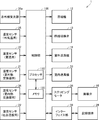
- FIG. 3 is a functional block diagram showing a functional configuration of the air conditioner 1 according to the first embodiment.
- the air conditioner 1 includes the outdoor control unit 29 and the indoor control unit 35.
- the outdoor control unit 29 and the indoor control unit 35 are collectively referred to as a control unit 100.
- the outdoor control unit 29 and the indoor control unit 35 can communicate with each other by wiring. And the process which the control part 100 performs may be fundamentally performed by the outdoor control part 29, and may be performed by the outdoor control part 29.
- FIG. 1
- the air conditioner 1 may not be provided with the indoor control unit 35, and almost all the functions of the control unit 100 may be mounted on the outdoor control unit 29. Alternatively, almost all functions of the control unit 100 may be mounted on the indoor control unit 35 without the air conditioner 1 having the outdoor control unit 29.
- the control unit 100 includes, for example, a processor 110 for performing various arithmetic processes and a memory 120 for storing various programs and data.
- the processor 110 is composed of, for example, a CPU (Central Processing Unit).
- the processor 110 executes various processes according to programs stored in the memory 120.
- the processor 110 controls the opening degree of the expansion valve 15 by controlling the stepping motor 38 according to a program.
- the memory 120 is realized by various RAMs (Random Access Memory), various ROMs (Read-Only Memory), flash memory, and the like.
- the air conditioner 1 may further include an interface unit 39 for reading and writing data and programs from a computer-readable non-transitory recording medium 28.
- the processor 110 may control the opening degree of the expansion valve 15 by storing the program read from the recording medium 28 by the interface unit 39 in the memory 120 or by updating an existing program. .
- USB Universal Serial Bus
- CD Compact Disc
- DVD Digital Versatile Disk
- memory card hard disk
- IC Integrated Circuit
- IC Integrated Circuit
- optical card mask ROM EPROM (Erasable Programmable Read Only Memory), EEPROM (Electronically Erasable Programmable Read-Only Memory), and the like.
- the opening degree of the expansion valve 15 is calculated as the number of phase excitation steps in the stepping motor 38.
- the expansion valve 15 is not limited to the one whose opening degree is adjusted by the stepping motor 38, and may be, for example, a temperature type expansion valve. That is, the temperature sensing cylinder enclosing the refrigerant and the expansion valve are connected, and the expansion valve has a structure separated by a diaphragm, and the temperature of the expansion valve is controlled by controlling the temperature of the temperature sensing cylinder and applying pressure to the diaphragm. Opening and closing may be controlled.
- control of the opening degree of the expansion valve 15 executed by the control unit 100 controls the opening degree of the expansion valve 15 so as to keep the degree of superheat of the evaporator at a predetermined value in order for the cycle to efficiently perform heat exchange.
- degree of superheat represents the temperature difference between the superheated steam temperature under a certain pressure and the dry saturated steam temperature.
- the processor 110 starts the defrosting operation when it is determined that the outdoor heat exchanger 14 is frosted during the heating operation. More specifically, the processor 110 determines that the outdoor heat exchanger 14 has been frosted when a predetermined condition is satisfied based on the temperature from the temperature sensor 21 for the outdoor heat exchanger 14, and the like. The switching valve 13 is switched to the cooling operation state. Then, the processor 110 determines the opening degree of the expansion valve 15 so that the target degree of superheat can be achieved when returning from the defrosting operation to the heating operation.
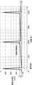
- FIG. 4 is a graph showing the relationship between the opening degree of the expansion valve 15 and the elapsed time in the air conditioner 1 in which the ideal or standard expansion valve 15 is mounted.
- FIG. 5 is a graph showing the relationship between the opening time of the expansion valve 15 and the elapsed time in the air conditioner 1 equipped with the expansion valve 15 having a smaller flow rate than the standard.
- FIG. 6 is a graph showing the relationship between the opening degree of the expansion valve 15 and the elapsed time in the air conditioner 1 equipped with the expansion valve 15 having a flow rate higher than that of the standard.
- the portion where the opening degree of the expansion valve 15 suddenly increases indicates when the defrosting operation is performed.
- the air conditioner 1 equipped with an ideal expansion valve 15 immediately after the completion of the first (n-th) defrosting operation, that is, from the start of the second (n + 1) -th heating operation.
- the change in the opening degree of the expansion valve 15 is small immediately before the start of the second (n + 1) defrosting operation, that is, immediately before the end of the second (n + 1) heating operation. That is, the refrigerant flow of the air conditioner 1 is stable and efficient operation is realized.
- the second (n + 1) heating operation starts from the second (n + 1) heating operation.
- the opening degree of the expansion valve 15 is increasing gradually until just before the end of the heating operation. That is, in this case, the refrigerant flow of the air conditioner 1 is not stable, and an efficient operation is not realized.
- the second time (n + 1) from the start of the second (n + 1) heating operation in the air conditioner 1 equipped with the expansion valve 15 having a smaller flow rate than the standard, the second time (n + 1) from the start of the second (n + 1) heating operation.
- the opening degree of the expansion valve 15 is gradually decreasing until immediately before the heating operation is completed. That is, also in this case, the flow of the refrigerant in the air conditioner 1 is not stable, and an efficient operation is not realized.
- the processor 110 includes the opening degree (Astep) of the expansion valve 15 immediately after the start of the first (n-th) heating operation and the expansion valve 15 immediately before the end of the first (n-th) heating operation.
- the correction value (Ystep) of the opening degree of the expansion valve 15 is determined in accordance with the difference (Xstep) between the opening degree (Bstep).
- the processor 110 adds a correction value (Ystep) to the value calculated as the opening degree of the expansion valve 15 immediately after the end of the second (n + 1) defrosting operation, that is, the third (n + 2) heating operation. .
- a correction value Ystep
- the change in the opening degree of the expansion valve 15 from the start of the third (n + 2) heating operation to just before the end of the third (n + 2) heating operation can be reduced.
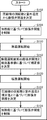
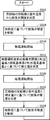
- FIG. 7 is a flowchart showing the expansion valve opening degree control process in the control unit 100 according to the present embodiment.
- processor 110 when heating operation is started, processor 110 first calculates the opening degree of expansion valve 15 based on the rotational speed of compressor 12 and the outdoor temperature (step S102). The processor 110 controls the stepping motor 38 to control the opening of the expansion valve 15 to the calculated opening. At this time, the processor 110 stores the opening of the expansion valve 15 at the start of the heating operation in the memory 120 as the opening reference value (Astep).
- the processor 110 controls the opening degree of the expansion valve 15 by controlling the stepping motor 38 so as to keep the heating degree of the outdoor heat exchanger 14 at a predetermined value (step S104).
- the processor 110 determines that the outdoor heat exchanger 14 is frosted when a predetermined condition is satisfied, and switches the four-way switching valve 13 to defrost. Operation starts (step S110). At this time, the processor 110 stores the opening degree of the expansion valve 15 immediately before the end of the heating operation in the memory 120 as the latest opening degree (Bstep).
- the processor 110 calculates an opening correction value (Ystep) based on the opening reference value (Astep) and the latest opening (Bstep) according to the above equation (1) (step S112).
- the processor 110 determines that the outdoor heat exchanger 14 has been defrosted when the predetermined condition is not satisfied, and switches to the heating operation (step S120).
- the processor 110 determines the opening degree of the expansion valve 15 at the start of the heating operation in consideration of the correction value (Ystep) (step S122).
- the processor 110 controls the stepping motor 38 to control the expansion valve 15 to the calculated opening.
- the processor 110 stores the opening of the expansion valve 15 at the start of the heating operation in the memory 120 as the opening reference value (Astep).
- the processor 110 controls the opening degree of the expansion valve 15 by controlling the stepping motor 38 so as to keep the heating degree of the outdoor heat exchanger 14 at a predetermined value (step S124).
- the processor 110 repeats the process from step S110.
- the difference between the opening (Astep) of the expansion valve 15 at the start of the n-th heating operation and the opening (Bstep) of the expansion valve 15 immediately before the end of the n-th heating operation (The correction value (Ystep) of the opening degree of the expansion valve 15 is determined so as to be proportional to Xstep).
- the control unit 100 may set the correction value (Ystep) step by step.
- the processor 110 ends the n-th defrosting operation when the opening degree (Bstep) of the expansion valve 15 immediately before the end of the n-th heating operation is larger than the opening reference value (Astep) by a first predetermined value or more.
- the correction value (Ystep) is determined so that the opening degree of the expansion valve at the time of the n + 1th heating operation immediately after that is larger by the second predetermined value than the opening degree reference value (Astep).
- the processor 110 performs the n-th defrosting operation when the opening degree (Bstep) of the expansion valve 15 immediately before the end of the n-th heating operation is smaller than the opening reference value (Astep) by a third predetermined value or more.
- the correction value (Ystep) is determined so that the opening degree of the expansion valve 15 during the (n + 1) th heating operation immediately after the end is made smaller by a fourth predetermined value than the opening degree reference value (Astep).
- the second predetermined value is smaller than the first predetermined value so as not to adversely affect other elements of the air conditioner 1 and to prevent overcorrection.
- the fourth predetermined value is preferably smaller than the third predetermined value.
- the first predetermined value is, for example, 40 steps.
- the second predetermined value is, for example, 30 steps.
- the third predetermined value is 40 steps, for example.
- the fourth predetermined value is, for example, 30 steps. Note that the first predetermined value and the third predetermined value may be different depending on the nature and purpose of the air conditioner 1. Similarly, the second predetermined value and the fourth predetermined value may be different.
- the expansion valve opening degree control process by the control unit 100 will be described, and the overall configuration of the air conditioner 1 and the basic operation of the air conditioner 1 are the same as those of the first embodiment. Since it is the same, description is not repeated here. And about the functional structure of the air conditioner 1, since the determination of the opening degree of an expansion valve is as above-mentioned description, since it is the same as that of 1st Embodiment about other functional structures, it is here. The explanation will not be repeated.
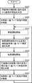
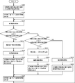
- FIG. 8 is a flowchart which shows the expansion valve opening degree control process in the control part 100 concerning this Embodiment.
- the processor 110 calculates the opening degree of the expansion valve 15 based on the rotation speed of the compressor 12 and the outdoor temperature (step S202).
- the processor 110 controls the stepping motor 38 to control the expansion valve 15 to the calculated opening.
- the processor 110 stores the opening of the expansion valve 15 at the start of the heating operation in the memory 120 as the opening reference value (Astep).
- the processor 110 controls the opening degree of the expansion valve 15 by controlling the stepping motor 38 so as to keep the heating degree of the outdoor heat exchanger 14 at a predetermined value (step S304).
- the processor 110 determines that the outdoor heat exchanger 14 is frosted when a predetermined condition is satisfied, and switches the four-way switching valve 13 to defrost. Operation is started (step S210). At this time, the processor 110 stores the opening degree of the expansion valve 15 immediately before the end of the heating operation in the memory 120 as the latest opening degree (Bstep).
- the processor 110 determines whether or not the difference between the opening degree reference value (Astep) and the latest opening degree (Bstep) is a predetermined value or more. That is, the processor 110 determines whether or not the latest opening degree (Bstep) ⁇ opening reference value (Astep) is equal to or greater than a first predetermined value (step S212). When the value of the latest opening degree (Bstep) ⁇ the opening degree reference value (Astep) is equal to or larger than the first predetermined value (YES in step S212), the processor 110 sets the second correction value (Ystep) as the second correction value (Ystep). Is set to a predetermined value (step S214).
- the processor 110 determines that the outdoor heat exchanger 14 has been defrosted when the predetermined condition is not satisfied, and switches to the heating operation (step S216).
- the processor 110 determines the opening degree of the expansion valve 15 at the start of the heating operation in consideration of the correction value (Ystep) (step S218).
- the processor 110 controls the stepping motor 38 to control the expansion valve 15 to the calculated opening.
- the processor 110 stores the opening of the expansion valve 15 at the start of the heating operation in the memory 120 as the opening reference value (Astep).
- the processor 110 controls the opening degree of the expansion valve 15 by controlling the stepping motor 38 so as to keep the heating degree of the outdoor heat exchanger 14 at a predetermined value (step S220).
- the processor 110 repeats the process from step S210.
- the processor 110 determines the opening reference value (Astep). -It is determined whether or not the latest opening degree (Bstep) is equal to or greater than a third predetermined value (step S222). When the value of the opening degree reference value (Astep) ⁇ the latest opening degree (Bstep) is equal to or greater than the third predetermined value (YES in step S222), the processor 110 sets the fourth correction value (Ystep) as the fourth correction value (Ystep). The predetermined value is converted to a negative value (step S224).
- the processor 110 determines that the outdoor heat exchanger 14 has been defrosted based on the temperature from the temperature sensor 21 for the outdoor heat exchanger, and switches to the heating operation (step S226).
- the processor 110 determines the opening degree of the expansion valve 15 at the start of the heating operation in consideration of the correction value (Ystep) (step S228).
- the processor 110 controls the stepping motor 38 to control the expansion valve 15 to the calculated opening.
- the processor 110 stores the opening of the expansion valve 15 at the start of the heating operation in the memory 120 as the opening reference value (Astep).
- the processor 110 repeats the process from step S220.
- the processor 110 reads the temperature sensor 21 for the outdoor heat exchanger. If the predetermined condition is no longer satisfied based on the temperature of the outdoor heat exchanger 14, it is determined that the outdoor heat exchanger 14 has been defrosted, and the operation is switched to the heating operation (step S236).
- the processor 110 calculates the opening degree of the expansion valve 15 based on the rotational speed of the compressor 12 and the outdoor temperature (step S238).
- the processor 110 controls the stepping motor 38 to control the expansion valve 15 to the calculated opening. At this time, the processor 110 stores the opening of the expansion valve 15 at the start of the heating operation in the memory 120 as the opening reference value (Astep).
- the processor 110 repeats the process from step S220.
- the correction value of the opening of the expansion valve 15 is changed only in one step in the positive direction and the negative direction in accordance with the change in the opening of the expansion valve 15.
- the correction value may be changed in multiple steps in a positive direction and a negative direction in accordance with a change in the opening degree of the expansion valve 15.
- the opening degree of the expansion valve 15 at the start of the first (n-th) heating operation is set to the opening degree of the expansion valve 15 at the start of the second (n + 1) -th heating operation.
- the opening reference value may be stored in advance in the memory 120 of the air conditioner 1.
- the memory 120 always stores 100 steps as the opening degree reference value (Astep).
- the control unit 100 may use the opening reference value as the expansion valve opening in step S102 in FIG. 7, step S202 in FIG. 8, and step S238.
- the opening reference value (Astep) for determining the opening of the expansion valve at the start of the n-th heating operation the opening of the expansion valve at the start of the n-2th heating operation or before may be used. Good.
- an opening reference value (Astep) for determining the opening degree of the expansion valve at the start of the n-th heating operation an average of the opening degree of the expansion valve at the start of a plurality of heating operations before the (n-1) th time A value may be used.
- the correction value (Ystep) for the opening of the expansion valve 15 is determined based on the difference (Xstep) between the opening (Bstep) of the expansion valve 15 immediately before the end of the second heating operation.
- the control unit 100 determines an ideal discharge temperature (D ° C.) immediately before the start of the defrosting operation in advance, and the ideal discharge temperature and the discharge temperature (E ° C.) of the compressor immediately before the end of the (n + 1) th heating operation.
- the correction value (Ystep) of the opening degree of the expansion valve 15 may be determined based on the difference (F ° C.).
- the processor 110 adds a correction value (Ystep) to the value calculated as the opening degree of the expansion valve 15 at the start of the second (n + 1) heating operation in FIGS.
- a correction value Ystep
- FIG. 9 is a flowchart which shows the expansion valve opening degree control process in the control part 100 concerning this Embodiment.
- the processor 110 stores a target ideal discharge temperature in the memory 120 as a discharge temperature reference value (D ° C.). Then, at the start of the N-th heating operation, the processor 110 calculates the opening degree of the expansion valve 15 based on the rotation speed of the compressor 12 and the outdoor temperature (step S302). The processor 110 controls the stepping motor 38 to control the expansion valve 15 to the calculated opening. At this time, the processor 110 stores the opening of the expansion valve 15 at the start of the heating operation in the memory 120 as the opening reference value (Astep).
- the processor 110 controls the opening degree of the expansion valve 15 by controlling the stepping motor 38 so as to keep the heating degree of the outdoor heat exchanger 14 at a predetermined value (step S304).
- the processor 110 determines that the outdoor heat exchanger 14 is frosted when a predetermined condition is satisfied, and switches the four-way switching valve 13 to defrost. Operation is started (step S310). At this time, the processor 110 stores the discharge temperature of the compressor 12 immediately before the start of the defrosting operation in the memory 120 as the latest discharge temperature (E ° C.).
- the processor 110 calculates the correction value (Ystep) of the opening degree based on the discharge temperature reference value (D ° C.) and the latest discharge temperature (E ° C.) according to the above equation (2) (step S312).
- the processor 110 determines that the outdoor heat exchanger 14 has been defrosted when the predetermined condition is not satisfied, and switches to the heating operation (step S320).
- the processor 110 determines the opening degree of the expansion valve 15 at the start of the heating operation in consideration of the correction value (Ystep) (step S322).
- the processor 110 controls the stepping motor 38 to control the expansion valve 15 to the calculated opening.
- the processor 110 stores the opening of the expansion valve 15 at the start of the heating operation in the memory 120 as the opening reference value (Astep).
- the processor 110 controls the opening degree of the expansion valve 15 by controlling the stepping motor 38 so as to keep the heating degree of the outdoor heat exchanger 14 at a predetermined value (step S324).
- the processor 110 repeats the process from step S310.
- the control unit 100 may set the correction value (Ystep) step by step.
- the processor 110 performs the n-th defrosting when the discharge temperature (E ° C.) of the compressor 12 immediately before the end of the n-th heating operation is higher than the discharge temperature reference value (D ° C.) by a fifth predetermined value or more.
- a correction value (Ystep) is determined so that the opening degree of the expansion valve at the start of the (n + 1) th heating operation immediately after the end of the operation is increased by a sixth predetermined value from the opening reference value.
- the processor 110 defrosts the nth time as the discharge temperature (E ° C.) of the compressor 12 immediately before the end of the nth heating operation is lower than the discharge temperature reference value (D ° C.) by a seventh predetermined value or more.
- the correction value (Ystep) is determined so that the opening degree of the expansion valve 15 during the (n + 1) th heating operation immediately after the end of the operation is made smaller by the eighth predetermined value than the opening degree reference value.
- the fifth predetermined value is 20 ° C., for example.
- the sixth predetermined value is, for example, 30 steps.
- the seventh predetermined value is, for example, 20 ° C.
- the eighth predetermined value is, for example, 30 steps. Note that the fifth predetermined value and the seventh predetermined value may be different depending on the nature and purpose of the air conditioner 1. Similarly, the sixth predetermined value and the eighth predetermined value may be different.
- the expansion valve opening degree control process by the control unit 100 will be described, and the overall configuration of the air conditioner 1 and the basic operation of the air conditioner 1 are the same as those of the first embodiment. Since it is the same, description is not repeated here. And about the functional structure of the air conditioner 1, since the determination of the opening degree of an expansion valve is as above-mentioned description, since it is the same as that of 1st Embodiment about other functional structures, it is here. The explanation will not be repeated.
- FIG. 10 is a flowchart which shows the expansion valve opening degree control process in the control part 100 concerning this Embodiment.
- the processor 110 stores a target ideal discharge temperature in the memory 120 as a discharge temperature reference value (D ° C.). Then, at the start of the N-th heating operation, the processor 110 calculates the opening degree of the expansion valve 15 based on the rotation speed of the compressor 12 and the outdoor temperature (step S402). The processor 110 controls the stepping motor 38 to control the expansion valve 15 to the calculated opening. At this time, the processor 110 stores the opening of the expansion valve 15 at the start of the heating operation in the memory 120 as the opening reference value (Astep).
- the processor 110 controls the opening degree of the expansion valve 15 by controlling the stepping motor 38 so as to keep the heating degree of the outdoor heat exchanger 14 at a predetermined value (step S404).
- the processor 110 determines that the outdoor heat exchanger 14 is frosted when a predetermined condition is satisfied, and switches the four-way switching valve 13 to defrost. Operation is started (step S410). At this time, the processor 110 stores the discharge temperature immediately before the start of the defrosting operation in the memory 120 as the latest discharge temperature (E ° C.).
- the processor 110 determines whether or not the difference between the discharge temperature reference value (D ° C.) and the latest discharge temperature (E ° C.) of the compressor 12 is a predetermined value or more. That is, the processor 110 determines whether or not the latest discharge temperature (E ° C.)-Discharge temperature reference value (D ° C.) of the compressor 12 is equal to or greater than a fifth predetermined value (step S412).
- a sixth predetermined value is set as (Ystep) (step S414).
- the processor 110 determines that the outdoor heat exchanger 14 has been defrosted when the predetermined condition is not satisfied, and switches to the heating operation (step S416).
- the processor 110 determines the opening degree of the expansion valve 15 at the start of the heating operation in consideration of the correction value (Ystep) (step S418).
- the processor 110 controls the stepping motor 38 to control the expansion valve 15 to the calculated opening.
- the processor 110 stores the opening of the expansion valve 15 at the start of the heating operation in the memory 120 as the opening reference value (Astep).
- the processor 110 controls the opening degree of the expansion valve 15 by controlling the stepping motor 38 so as to keep the heating degree of the outdoor heat exchanger 14 at a predetermined value (step S420).
- the processor 110 repeats the process from step S410.
- the processor 110 Temperature reference value (D ° C.) — Determines whether or not the latest discharge temperature (E ° C.) value of the compressor 12 is equal to or higher than a seventh predetermined value (step S422).
- the processor 110 determines a correction value when the discharge temperature reference value (D ° C.) ⁇
- the latest discharge temperature (E ° C.) of the compressor 12 is equal to or higher than a seventh predetermined value (YES in step S422).
- a value obtained by converting the eighth predetermined value into a negative value is set as (Ystep) (step S424).
- the processor 110 determines that the outdoor heat exchanger 14 has been defrosted based on the temperature from the temperature sensor 21 for the outdoor heat exchanger, and switches to heating operation (step S426).
- the processor 110 determines the opening degree of the expansion valve 15 at the start of the heating operation in consideration of the correction value (Ystep) (step S428).
- the processor 110 controls the stepping motor 38 to control the expansion valve 15 to the calculated opening.
- the processor 110 stores the opening of the expansion valve 15 at the start of the heating operation in the memory 120 as the opening reference value (Astep).
- the processor 110 repeats the process from step S420.
- the processor 110 When the discharge temperature reference value (D ° C.) ⁇ The latest discharge temperature (E ° C.) of the compressor 12 is less than the seventh predetermined value (NO in step S422), the processor 110 performs outdoor heat exchange. Based on the temperature from the temperature sensor 21 for the appliance, when the predetermined condition is not satisfied, it is determined that the outdoor heat exchanger 14 has been defrosted and switched to the heating operation (step S436). The processor 110 calculates the opening degree of the expansion valve 15 based on the rotation speed of the compressor 12 and the outdoor temperature (step S438). The processor 110 controls the stepping motor 38 to control the expansion valve 15 to the calculated opening. At this time, the processor 110 stores the opening of the expansion valve 15 at the start of the heating operation in the memory 120 as the opening reference value (Astep).
- the correction value of the opening of the expansion valve 15 is changed by one step in the positive direction and the negative direction in accordance with the change in the discharge temperature of the compressor 12.
- the correction value may be changed in multiple steps in a positive direction and a negative direction in accordance with the change in the discharge temperature of the compressor 12.
- the correction value (Ystep) for the opening of the expansion valve 15 is determined based on the difference (Xstep) between the opening (Bstep) of the expansion valve 15 immediately before the end of the second heating operation.
- the controller 100 immediately after the completion of the n-th defrosting operation, that is, the opening degree (Astep) of the expansion valve 15 at the start of the (n + 1) -th heating operation, and immediately before the start of the (n + 1) -th defrosting operation, ie, the end of the (n + 1) -th heating operation.
- the correction value (Ystep) of the opening degree of the expansion valve 15 may be determined based on the difference (F ° C.) from the discharge temperature (E ° C.).
- the processor 110 corrects the value to the value calculated as the opening degree of the expansion valve 15 immediately after the end of the second (n + 1) defrosting operation in FIGS. 4 to 6, that is, the third (n + 2) heating operation start. Add the value (Ystep). As a result, the change in the opening degree of the expansion valve 15 from the start of the third (n + 2) heating operation to just before the end of the third (n + 2) heating operation is reduced and brought closer to the ideal discharge temperature. Is possible.
- FIG. 11 is a flowchart which shows the expansion valve opening degree control process in the control part 100 concerning this Embodiment.
- the processor 110 stores a target ideal discharge temperature in the memory 120 as a discharge temperature reference value (D ° C.). Then, at the start of the N-th heating operation, the processor 110 calculates the opening degree of the expansion valve 15 based on the rotation speed of the compressor 12 and the outdoor temperature (step S502). The processor 110 controls the stepping motor 38 to control the expansion valve 15 to the calculated opening. At this time, the processor 110 stores the opening degree of the expansion valve 15 at the start of the N-th heating operation in the memory 120 as the opening reference value (Astep).
- the processor 110 controls the opening degree of the expansion valve 15 by controlling the stepping motor 38 so as to keep the heating degree of the outdoor heat exchanger 14 at a predetermined value (step S504).
- the processor 110 determines that the outdoor heat exchanger 14 is frosted when a predetermined condition is satisfied, and switches the four-way switching valve 13 to defrost. Operation is started (step S510). At this time, the processor 110 stores the opening degree of the expansion valve 15 immediately before the start of the defrosting operation in the memory 120 as the latest opening degree (Bstep). At this time, the processor 110 stores the discharge temperature of the compressor 12 immediately before the start of the defrosting operation in the memory 120 as the latest discharge temperature (E ° C.).
- the processor 110 A correction value (Ystep) of the opening is calculated (step S512).
- the processor 110 determines that the outdoor heat exchanger 14 has been defrosted when the predetermined condition is not satisfied, and switches to the heating operation (step S520).
- the processor 110 determines the opening degree of the expansion valve 15 at the start of the heating operation in consideration of the correction value (Ystep) (step S522).
- the processor 110 controls the stepping motor 38 to control the expansion valve 15 to the calculated opening.
- the processor 110 stores the opening of the expansion valve 15 at the start of the heating operation in the memory 120 as the opening reference value (Astep).
- the processor 110 controls the opening degree of the expansion valve 15 by controlling the stepping motor 38 so as to keep the heating degree of the outdoor heat exchanger 14 at a predetermined value (step S504).
- the processor 110 repeats the process from step S510.
- the opening degree (Astep) of the expansion valve 15 immediately after the end of the nth defrosting operation that is, the start of the n + 1th heating operation
- the time immediately before the start of the n + 1th defrosting operation that is, the n + 1th heating. It is proportional to the difference (Xstep) between the opening degree (Bstep) of the expansion valve 15 immediately before the end of the operation, and the ideal compressor discharge temperature (D ° C.) of the compressor 12 and the (n + 1) th time.
- the correction value (Ystep) of the opening degree of the expansion valve 15 is determined so as to be proportional to the difference (F ° C) between the discharge temperature (E ° C) of the compressor 12 immediately before the end of the heating operation.
- the control unit 100 may set the correction value (Ystep) step by step.
- the processor 110 determines that the opening degree (Bstep) of the expansion valve 15 immediately before the start of the n-th defrosting operation is larger than the opening reference value (Astep) by a first predetermined value and / or the n-th time.
- the discharge temperature (E ° C) of the compressor 12 immediately before the start of the defrosting operation is higher than the discharge temperature reference value (D ° C) by a fifth predetermined value or more, the n + 1th heating immediately after the end of the nth defrosting operation.
- a correction value (Ystep) is determined so that the opening of the expansion valve during operation is increased by a ninth predetermined value from the opening reference value.
- the processor 110 determines that the opening degree (Bstep) of the expansion valve 15 immediately before the start of the nth defrosting operation is smaller than the opening reference value (Astep) by a third predetermined value and / or nth time.
- the discharge temperature (E ° C) of the compressor 12 immediately before the start of the defrosting operation is lower than the discharge temperature reference value (D ° C) by a seventh predetermined value or more, the n + 1th heating immediately after the end of the nth defrosting operation
- a correction value (Ystep) is determined so that the opening degree of the expansion valve 15 during operation is made smaller by a tenth predetermined value than the opening degree reference value.
- the first to fourth predetermined values have the same properties as those of the second embodiment.
- the fifth to eighth predetermined values have the same properties as those of the fourth embodiment.
- the 9th predetermined value is 45step, for example.
- the 10th predetermined value is 45step, for example.
- the ninth predetermined value is, for example, 30 steps.
- the tenth predetermined value is, for example, 30 steps. Note that the ninth predetermined value and the tenth predetermined value may be different depending on the nature and purpose of the air conditioner 1.
- FIG. 12 is a flowchart which shows the expansion valve opening degree control process in the control part 100 concerning this Embodiment.
- the processor 110 stores a target ideal discharge temperature in the memory 120 as a discharge temperature reference value (D ° C.). Then, at the start of the N-th heating operation, the processor 110 calculates the opening degree of the expansion valve 15 based on the rotation speed of the compressor 12 and the outdoor temperature (step S602). The processor 110 controls the stepping motor 38 to control the expansion valve 15 to the calculated opening. At this time, the processor 110 stores the opening degree of the expansion valve 15 at the start of the N-th heating operation in the memory 120 as the opening reference value (Astep).
- the processor 110 controls the opening degree of the expansion valve 15 by controlling the stepping motor 38 so as to keep the heating degree of the outdoor heat exchanger 14 at a predetermined value (step S604).
- the processor 110 determines that frost has formed on the outdoor heat exchanger 14 when a predetermined condition is satisfied, and stores the discharge temperature of the compressor 12 at that time in the memory 120. And defrosting operation is started by switching the four-way switching valve 13 (step S610). At this time, the processor 110 stores the opening degree of the expansion valve 15 immediately before the start of the defrosting operation, that is, immediately before the end of the heating operation, in the memory 120 as the latest opening degree (Bstep). At this time, the processor 110 stores the discharge temperature of the compressor 12 immediately before the end of the heating operation in the memory 120 as the latest discharge temperature (E ° C.).
- the processor 110 determines whether or not the difference between the opening reference value (Astep) and the latest opening (Bstep) is a predetermined value or more, and / or the discharge temperature reference value (D ° C) and the latest compressor 12. It is determined whether or not the difference from the discharge temperature (E ° C.) is a predetermined value or more. That is, the processor 110 determines whether or not the latest opening degree (Bstep) ⁇ opening reference value (Astep) is equal to or higher than the first predetermined value and / or the discharge temperature (E of the latest compressor 12). ° C.) — Discharge temperature reference value (D ° C.) is determined whether it is equal to or greater than a fifth predetermined value (step S612).
- the processor 110 determines that the latest opening (Bstep) ⁇ opening reference value (Astep) is equal to or greater than the first predetermined value and / or the latest discharge temperature (E ° C.) of the compressor 12 ⁇ discharge. If the value of the temperature reference value (D ° C.) is greater than or equal to the fifth predetermined value (YES in step S612), a ninth predetermined value is set as the correction value (Ystep) (step S614).
- the processor 110 determines that the outdoor heat exchanger 14 has been defrosted when the predetermined condition is not satisfied, and switches to the heating operation (step S616).
- the processor 110 determines the opening degree of the expansion valve 15 at the start of the heating operation in consideration of the correction value (Ystep) (step S618).
- the processor 110 controls the stepping motor 38 to control the expansion valve 15 to the calculated opening.
- the processor 110 stores the opening of the expansion valve 15 at the start of the heating operation in the memory 120 as the opening reference value (Astep).
- the processor 110 controls the opening degree of the expansion valve 15 by controlling the stepping motor 38 so as to keep the heating degree of the outdoor heat exchanger 14 at a predetermined value (step S620).
- the processor 110 repeats the process from step S610.
- the processor 110 determines that the latest opening degree (Bstep) ⁇ the opening degree reference value (Astep) is less than the first predetermined value and / or the discharge temperature (E ° C.) of the latest compressor 12 ⁇ discharge.
- the opening reference value (Astep) ⁇ the latest opening (Bstep) value is the third value. It is determined whether or not the discharge temperature reference value (D ° C.) ⁇ The latest discharge temperature (E ° C.) of the compressor 12 is equal to or higher than a seventh predetermined value. (Step S622).
- the processor 110 determines whether the opening degree reference value (Astep) ⁇ the latest opening degree (Bstep) is equal to or greater than a third predetermined value and / or the discharge temperature reference value (D ° C.) ⁇ The latest compressor 12. If the value of the discharge temperature (E ° C.) is equal to or higher than the seventh predetermined value (YES in step S622), the tenth predetermined value converted to a negative value as the correction value (Ystep) Setting is made (step S624).
- the processor 110 determines that the outdoor heat exchanger 14 has been defrosted based on the temperature from the temperature sensor 21 for the outdoor heat exchanger, and switches to the heating operation (step S626).
- the processor 110 determines the opening degree of the expansion valve 15 at the start of the heating operation in consideration of the correction value (Ystep) (step S628).
- the processor 110 controls the stepping motor 38 to control the expansion valve 15 to the calculated opening.
- the processor 110 stores the opening of the expansion valve 15 at the start of the heating operation in the memory 120 as the opening reference value (Astep).
- the processor 110 repeats the process from step S620.
- the processor 110 determines whether the opening degree reference value (Astep) ⁇ the latest opening degree (Bstep) value is less than a third predetermined value and / or the discharge temperature reference value (D ° C.) ⁇ The latest compressor 12. Is less than the seventh predetermined value (NO in step S622), a predetermined condition is satisfied based on the temperature from the temperature sensor 21 for the outdoor heat exchanger. If it runs out, it will be judged that the outdoor heat exchanger 14 has been defrosted, and it will switch to heating operation (step S636).
- the processor 110 calculates the opening degree of the expansion valve 15 based on the rotation speed of the compressor 12 and the outdoor temperature (step S638).
- the processor 110 controls the stepping motor 38 to control the expansion valve 15 to the calculated opening. At this time, the processor 110 stores the opening of the expansion valve 15 at the start of the heating operation in the memory 120 as the opening reference value (Astep).
- the processor 110 repeats the process from step S620.
- step S612 and step S622 of FIG. 12 when the processor 110 makes a determination of YES based on the description “and”, NO is determined based on the description “or”. Judgment should be made. Conversely, if the processor 110 makes a determination of YES based on the description “or”, the processor 110 should make a determination of NO based on the description “and”.
- the correction value of the opening degree of the expansion valve 15 is set to 1 in the positive direction and the negative direction in accordance with the change in the opening degree of the expansion valve 15 and the change in the discharge temperature of the compressor 12. Although it is changed in steps, the correction value may be changed in multiple steps in a positive direction and a negative direction in accordance with a change in the opening of the expansion valve 15 and a change in the discharge temperature of the compressor 12. .
- the opening degree of the expansion valve 15 at the start of the second (n + 1) th heating operation immediately after the completion of the first (nth) defrosting operation that is, the second (n + 1)
- the opening reference value (Astep) when determining the opening of the expansion valve 15 at the start of the second heating operation, the present invention is not limited to such a form.
- the opening reference value may be stored in advance in the memory 120 of the air conditioner 1.
- the control unit 100 may use the opening reference value as the expansion valve opening in step S502 in FIG. 11 and in steps S602 and S638 in FIG.
- the opening reference value (Astep) for determining the opening of the expansion valve at the start of the n-th heating operation the opening of the expansion valve at the start of the n-2th heating operation or before may be used. Good.
- an opening reference value (Astep) for determining the opening degree of the expansion valve at the start of the n-th heating operation an average of the opening degree of the expansion valve at the start of a plurality of heating operations before the (n-1) th time A value may be used.
- Air conditioner 10 Outdoor unit 12: Compressor 13: Four-way switching valve 14: Outdoor heat exchanger 15: Expansion valve 16: Outdoor blower 17: Refrigerant pipe 18: Refrigerant pipe 19: Two-way valve 20: Three-way valve 21: Outdoor heat exchanger temperature sensor 22: Discharge temperature sensor 23: Suction temperature sensor 24: Outlet temperature sensor 25: Outside air temperature sensor 28: Recording medium 29: Outdoor control unit 30: Indoor unit 32: Indoor heat exchanger 33: Indoor Blower 34: Indoor heat exchanger temperature sensor 35: Indoor controller 37: Indoor temperature sensor 38: Stepping motor 39: Interface unit 50: Remote controller 100: Control unit 110: Processor 120: Memory
Landscapes
- Engineering & Computer Science (AREA)
- Mechanical Engineering (AREA)
- General Engineering & Computer Science (AREA)
- Physics & Mathematics (AREA)
- Thermal Sciences (AREA)
- Chemical & Material Sciences (AREA)
- Combustion & Propulsion (AREA)
- Air Conditioning Control Device (AREA)
- Compression-Type Refrigeration Machines With Reversible Cycles (AREA)
Abstract
膨張弁の流量が標準よりも多い場合あるいは少ない場合であっても、暖房運転中の膨張弁の開度の変化を従来よりも低減させることができる、空気調和機を提供する。 膨張弁15と圧縮機12とを含む空気調和機構2と、制御部100と、を備える空気調和機1が提供される。制御部100は、除霜動作の直前の膨張弁15の開度に基づいて補正値を決定し、除霜動作の終了後に補正値に基づいて暖房運転時の膨張弁15の開度を設定する。
Description
本発明は、空気調和機の技術に関し、より詳細には空気調和機の膨張弁を制御するための技術に関する。
一般に、空気調和機は、圧縮機、切換弁、室外熱交換器、減圧を行う際に冷媒流量を調節する膨張弁、室内熱交換器等の部品が接続されて冷凍サイクルが構成されている。このような空気調和機では、切換弁を切り換えることで、冷凍サイクルを冷房運転サイクルおよび暖房運転サイクルのいずれかに切り換えることができる。
そして、冷房運転サイクルでは、圧縮機、切換弁、室外熱交換器(凝縮器)、膨張弁、室内熱交換器(蒸発器)、切換弁、圧縮機の順に冷媒が循環し、これにより、室内熱交換器で吸収した室内の熱が室外熱交換器で室外に放出される。
また、暖房運転サイクルでは、圧縮機、切換弁、室内熱交換器(凝縮器)、膨張弁、室外熱交換器(蒸発器)、切換弁、圧縮機の順に冷媒が循環し、これにより、室外熱交換器で吸収した室外の熱が室内熱交換器で室内に放出される。
上記のような熱交換サイクルを形成する際に、蒸発器の温度と蒸発器の出口温度とを検出することによって過熱度を計算し、その過熱度を用いて膨張弁の開度を制御することが一般的である。そして、従来から、空気調和機の膨張弁の制御に関して様々な方法が知れている。
たとえば、特開2012-127525号公報(特許文献1)には、空気調和機、膨張弁の開度制御方法およびプログラムが開示されている。特開2012-127525号公報(特許文献1)によると、空気調和機は、圧縮機の出口での冷媒の温度を吐出温度として検出する第1の温度センサと、凝縮器(1または3)の温度を検出する第2の温度センサとを備える。制御部は、現在までの複数の時点で検出された圧縮機の吐出温度を外挿することによって未来の予測吐出温度を算出し、算出した予測吐出温度と凝縮器の現在の温度との温度差を過熱度として算出し、算出した過熱度に基づいて膨張弁の開度を設定する。
さらに、特開2002-349936公報(特許文献2)には、空気調和機の制御方法が開示されている。特開2002-349936号公報(特許文献2)によると、冷凍サイクルを構成する膨張弁の開閉度合を制御する空気調和機の制御方法において、運転数に対応する周波数ゾーンを判断し、開閉度合テーブルを参照して選択周波数ゾーンに応じた開閉度合を読み出すとともに、膨張弁を読み出した開閉度合に制御する。そして、外気温度を検出し、外気温度に対応するゾーンを判断し、判断したゾーンが中間的温度のYゾーンであるときには、膨張弁の現開閉度合を維持する。判断したゾーンが低い温度のXゾーンであるときには、現開閉度合(固定パルス)に-5パルスを加算して膨張弁を絞る方向に制御し、そのゾーンが高い温度のZゾーンであるときには現開閉度合(固定パルス)に+10パルスを加算して膨張弁を開く方向に制御する。
さらに、特開平8-226715公報(特許文献3)には、ヒートポンプ式空気調和機が開示されている。特開平8-226715号公報(特許文献3)によると、圧縮機、四方弁、室内熱交換器、絞り機構、室外熱交換器等が組み込まれた閉回路を冷媒が循環する冷凍サイクルを有するヒートポンプ式空気調和機において、室外熱交換器の温度分布の検出を行なう検出手段と、検出手段によって検出された検出値に基づいて流量を調整する流量調整手段と、流量調整手段を制御する制御手段と、を備えたことを特徴とするものである。
しかしながら、空気調和機のために製造される膨張弁は、流量が全て一定であるとは限らない。たとえば、製造された複数の膨張弁の中には、同じ開度における流量が標準値から離れた膨張弁が混じっている場合がある。本発明の目的は、膨張弁の流量が標準よりも多い場合あるいは少ない場合であっても、暖房運転中の膨張弁の開度の変化を従来よりも低減させることができる、空気調和機、空気調和機の制御方法、および空気調和機のための制御プログラムを提供することにある。
この発明のある態様に従うと、膨張弁と圧縮機とを含む空気調和機構と、制御部と、を備える空気調和機が提供される。制御部は、除霜動作の直前の膨張弁の開度に基づいて補正値を決定し、除霜動作の終了後に補正値に基づいて暖房運転時の膨張弁の開度を設定する。
好ましくは、制御部は、除霜動作の直前の膨張弁の開度が開度基準値よりも大きいほど、除霜動作の終了後の暖房運転時の膨張弁の開度を大きくするよう補正値を決定する。制御部は、除霜動作の直前の膨張弁の開度が開度基準値よりも小さいほど、除霜動作の終了後の暖房運転時の膨張弁の開度を小さくするよう補正値を決定する。
好ましくは、制御部は、除霜動作の直前の膨張弁の開度が開度基準値よりも第1の所定値以上大きい場合に、除霜動作の終了後の暖房運転時の膨張弁の開度を開度基準値よりも第2の所定値だけ大きくするよう補正値を決定する。制御部は、除霜動作の直前の膨張弁の開度が第1の基準値よりも第3の所定値以上小さい場合、除霜動作の終了後の暖房運転時の膨張弁の開度を開度基準値よりも第4の所定値だけ小さくするよう補正値を決定する。第2の所定値は、第1の所定値よりも小さい。第4の所定値は、第3の所定値よりも小さい。
好ましくは、制御部は、除霜動作の直前の圧縮機の吐出温度にも基づいて補正値を決定する。制御部は、除霜動作の直前の圧縮機の吐出温度が吐出温度基準値よりも高いほど、除霜動作の終了後の暖房運転時の膨張弁の開度を大きくするよう補正値を決定する。制御部は、除霜動作の直前の圧縮機の吐出温度が吐出温度基準値よりも低いほど、除霜動作の終了後の暖房運転時の膨張弁の開度を小さくするよう補正値を決定する。
好ましくは、制御部は、除霜動作の直前の圧縮機の吐出温度が吐出温度基準値よりも第5の所定値以上高い場合に、除霜動作の終了後の暖房運転時の膨張弁の開度を開度基準値よりも第6の所定値だけ大きくするよう補正値を決定する。制御部は、除霜動作の直前の圧縮機の吐出温度が吐出温度基準値よりも第7の所定値以上低いほど、除霜動作の終了後の暖房運転時の膨張弁の開度を開度基準値よりも第8の所定値だけ小さくするよう補正値を決定する。
好ましくは、制御部は、基準値を記憶している。
好ましくは、制御部は、前回以前のいずれかの除霜動作の直後の膨張弁の開度を開度基準値とする。
この発明の別の態様に従うと、膨張弁と圧縮機とを含む空気調和機構と、制御部と、を含む空気調和機における制御方法が提供される。制御方法は、制御部が、除霜動作の直前の膨張弁の開度を取得するステップと、制御部が、除霜動作の直前の膨張弁の開度から補正値を決定するステップと、制御部が、空気調和機構に除霜動作を実行させるステップと、制御部が、除霜動作の終了後に、補正値に基づいて暖房運転時の膨張弁の開度を設定するステップと、制御部が、設定された開度に基づいて空気調和機構に暖房動作を実行させるステップと、を備える。
この発明の別の態様に従うと、膨張弁と圧縮機とを含む空気調和機構と、プロセッサと、を含む空気調和機のための制御プログラムが提供される。制御プログラムは、除霜動作の直前の膨張弁の開度を取得するステップと、除霜動作の直前の膨張弁の開度から補正値を決定するステップと、空気調和機構に除霜動作を実行させるステップと、除霜動作の終了後に、補正値に基づいて暖房運転時の膨張弁の開度を設定するステップと、設定された開度に基づいて空気調和機構に暖房動作を実行させるステップと、をプロセッサに実行させる。
以上のように、この発明によれば、膨張弁の流量が標準よりも多い場合あるいは少ない場合であっても、暖房運転中の膨張弁の開度の変化を従来よりも低減させることができる、空気調和機、空気調和機の制御方法、および空気調和機のための制御プログラムが提供される。
以下、図面を参照しつつ、本発明の実施の形態について説明する。以下の説明では、同一の部品には同一の符号を付してある。それらの名称および機能も同じである。したがって、それらについての詳細な説明は繰り返さない。
<第1の実施の形態>
<空気調和機の全体構成>
<第1の実施の形態>
<空気調和機の全体構成>
まず、本実施の形態にかかる空気調和機1の全体構成と基本的な動作概要とについて説明する。なお、図1は、第1の実施の形態にかかる空気調和機の冷房運転時および除霜運転時の概略構成図である。また、図2は、第1の実施の形態にかかる空気調和機の暖房運転時の概略構成図である。
図1および図2を参照して、本実施の形態にかかる空気調和機1は、セパレート式の空気調和機であって、主に、室外機10、室内機30およびリモートコントローラ50から構成されている。なお、空気調和機1は、室内機30と室外機10とが冷媒配管17および18を介して接続されることによって構成されている。以下、室外機10、室内機30、リモートコントローラ50、冷媒配管17および18について詳述する。
(1)室外機
室外機10は、主に、筐体11、圧縮機12、四路切換弁13、室外熱交換器14、膨張弁15、室外送風機16、冷媒配管17、冷媒配管18、二方弁19、三方弁20、室外熱交換器温度センサ21、吐出温度センサ22、吸入温度センサ23、出口温度センサ24、外気温度センサ25および室外制御部29から構成されている。なお、この室外機10は、屋外に設置されている。
室外機10は、主に、筐体11、圧縮機12、四路切換弁13、室外熱交換器14、膨張弁15、室外送風機16、冷媒配管17、冷媒配管18、二方弁19、三方弁20、室外熱交換器温度センサ21、吐出温度センサ22、吸入温度センサ23、出口温度センサ24、外気温度センサ25および室外制御部29から構成されている。なお、この室外機10は、屋外に設置されている。
筐体11には、圧縮機12、四路切換弁13、室外熱交換器14、膨張弁15、室外送風機16、冷媒配管17、冷媒配管18、二方弁19、三方弁20、温度センサ21~25および室外制御部29等が収納されている。
圧縮機12は、吐出管12aおよび吸入管12bを有している。吐出管12aおよび吸入管12bは、それぞれ、四路切換弁13の異なる接続口に接続されている。また、圧縮機12は、通信線を介して室外制御部29に通信接続されており、室外制御部29から送信される制御信号に従って動作する。圧縮機12は、運転時、吸入管12bから低圧の冷媒ガスを吸入し、その冷媒ガスを圧縮して高圧の冷媒ガスを生成した後、その高圧の冷媒ガスを吐出管12aから吐出する。なお、本実施の形態において、この圧縮機12の制御形式は、特に限定されず、定速式の圧縮機であってもよいし、インバータ式の圧縮機であってもよい。
四路切換弁13は、冷媒配管を介して圧縮機12の吐出管12aおよび吸入管12b、室外熱交換器14ならびに室内熱交換器32に接続されている。そして、この四路切換弁13は、通信線を介して室外制御部29に通信接続されており、室外制御部29から送信される制御信号に従って動作する。これによって、四路切換弁13は、運転時、室外制御部29から送信される制御信号に従って、圧縮機12の吐出管12aを室外熱交換器14に連結させると共に圧縮機12の吸入管12bを室内熱交換器32に連結させる冷房運転状態(図1参照)と、圧縮機12の吐出管12aを室内熱交換器32に連結させると共に圧縮機12の吸入管12bを室外熱交換器14に連結させる暖房運転状態(図2参照)とを切り換える。
室外熱交換器14は、左右両端で複数回折り返された伝熱管(図示せず)に多数の放熱フィン(図示せず)が取り付けられたもの(フィン&チューブ型)であって、冷房運転時(図1参照)には凝縮器として機能し、暖房運転時(図2参照)には蒸発器として機能する。なお、熱交換器としてパラレルフロー型熱交換器やサーペン型熱交換器を用いてもよい。
膨張弁15は、後述するステッピングモータを介して開度制御が可能な電子膨張弁であって、一方が冷媒配管17を介して二方弁19に接続されると共に、他方が室外熱交換器14に接続されている。また、この膨張弁15のステッピングモータは、通信線を介して室外制御部29に通信接続されており、室外制御部29から送信される制御信号に従って動作する。膨張弁15は、運転時において、凝縮器(冷房時は室外熱交換器14であり、暖房時は室内熱交換器32である)から流出する高温高圧の液冷媒を蒸発しやすい状態に減圧すると共に、蒸発器(冷房時は室内熱交換器32であり、暖房時は室外熱交換器14である)への冷媒供給量を調節する役目を担っている。
室外送風機16は、主に、プロペラファンおよびモータから構成されている。プロペラファンは、モータによって回転駆動され、屋外の外気を室外熱交換器14に供給する。モータは、通信線を介して室外制御部29に通信接続されており、室外制御部29から送信される制御信号に従って動作する。
二方弁19は、冷媒配管17に配設されている。なお、二方弁19は、室外機10から冷媒配管17が取り外されるときに閉じられ、冷媒が室外機10から外部に漏れることを防ぐ。
三方弁20は、冷媒配管18に配設されている。なお、三方弁20は、室外機10から冷媒配管18が取り外されるときに閉じられ、冷媒が室外機10から外部に漏れることを防ぐ。また、室外機10から、あるいは室内機30を含めた冷凍サイクル全体から、冷媒を回収する必要があるときは、三方弁20を通じて冷媒の回収が行われる。
温度センサ21~25は、サーミスタである。室外熱交換器温度センサ21は室外熱交換器14に配置されており、吐出温度センサ22は圧縮機12の吐出管12aに配置されており、吸入温度センサ23は圧縮機12の吸入管12bに配置されており、出口温度センサ24は室外熱交換器14の出口付近の冷媒配管17に配置されており、外気温度センサ25は外気温度測定用であって筐体11の内部の所定箇所に配置されている。これらの温度センサ21~25は、全て、通信線を介して室外制御部29に通信接続されており、計測された温度に関する情報を室外制御部29に送信している。
室外制御部29は、通信線を介して圧縮機12、四路切換弁13、膨張弁15、室外送風機16および温度センサ21~25に通信接続されている。たとえば、室外制御部29のプロセッサは、随時、温度センサ21~25の出力情報や、メモリに記憶される種々の制御パラメータ等を演算処理して適切な制御パラメータを導出し、その制御パラメータを、圧縮機12や、四路切換弁13、膨張弁15、室外送風機16に送信する。また、プロセッサは、必要に応じて、制御パラメータ等を室内制御部35に送信したり、受信したりする。
(2)室内機
室内機30は、主に、筐体31、室内熱交換器32、室内送風機33、フラップ36、室内熱交換器温度センサ34、室内温度センサ37および室内制御部35から構成されている。なお、この室内機30は、一般的に室内の壁面に設置されている。
室内機30は、主に、筐体31、室内熱交換器32、室内送風機33、フラップ36、室内熱交換器温度センサ34、室内温度センサ37および室内制御部35から構成されている。なお、この室内機30は、一般的に室内の壁面に設置されている。
筐体31には、室内熱交換器32、室内送風機33、室内熱交換器温度センサ34、室内温度センサ37および室内制御部35等が収納されている。フラップ36は、筐体31の一部を構成している。
室内熱交換器32は、3個の熱交換器32A、32B、32Cを、室内送風機33を覆う屋根のように組み合わせたものである。なお、各熱交換器32A、32B、32Cは、左右両端で複数回折り返された伝熱管(図示せず)に多数の放熱フィン(図示せず)が取り付けられたものであって、冷房運転時(図1参照)には蒸発器として機能し、暖房運転時(図2参照)には凝縮器として機能する。
室内送風機33は、主に、クロスフローファンおよびモータから構成されている。クロスフローファンは、モータによって回転駆動され、室内の空気を筐体31に吸い込んで室内熱交換器32に供給すると共に、室内熱交換器32で熱交換された空気を室内に送出する。モータは、通信線を介して室内制御部35に通信接続されており、室内制御部35から送信される制御信号に従って動作する。
フラップ36は、風向板およびモータから構成されている。フラップは、モータによって回動され、クロスフローファンによって室内に送出される空気の送出方向を調節する。モータは、通信線を介して室内制御部35に通信接続されており、室内制御部35から送信される制御信号に従って動作する。
温度センサ34,37は、サーミスタである。室内熱交換器温度センサ34は室内熱交換器32に配置されており、室内温度センサ37は、室内温度を測定するものであって筐体31内の吸込口付近に配置されている。温度センサ34,37は、通信線を介して室内制御部35に通信接続されており、計測された温度に関する情報を室内制御部35に送信している。
室内制御部35は、通信線を介して室内送風機33、フラップ36および温度センサ34,37に通信接続されている。室内制御部35のプロセッサは、随時、リモートコントローラ50からの制御信号や、温度センサ34,37の出力情報等を演算処理して適切な制御パラメータを導出し、その制御パラメータ等を、室内送風機33や、フラップ36に送信する。また、プロセッサは、必要に応じて、制御パラメータ等を室外制御部29に送信したり、制御パラメータ等を室外制御部29から受信したりする。赤外線受光部35aは、リモートコントローラ50から発生される点滅赤外線を受光するものである。この赤外線受光部35aは、点滅赤外線を信号化処理し、生成した信号を室内制御部35に受け渡す。
なお、室外機10の圧縮機12、四路切換弁13、室外熱交換器14および膨張弁15、ならびに室内機30の室内熱交換器32は、冷媒配管17,18によって順次接続され、冷媒回路を構成している。本実施の形態において、この冷媒回路、室外送風機16、室内送風機33およびフラップ36を併せて空気調和機構と称し、図1および図2中において符号2で示す。
(3)リモートコントローラ
リモートコントローラ50は、点滅赤外線を利用してユーザの様々な指令を室内機30の室内制御部35に伝達するためのものであって、主に、赤外線発光部、表示パネル、運転停止ボタン、モード切換ボタン、温度上昇ボタン、温度下降ボタン、風量上昇ボタン、風量下降ボタン、風向調節ボタン、自動運転ボタン等から構成されている。
リモートコントローラ50は、点滅赤外線を利用してユーザの様々な指令を室内機30の室内制御部35に伝達するためのものであって、主に、赤外線発光部、表示パネル、運転停止ボタン、モード切換ボタン、温度上昇ボタン、温度下降ボタン、風量上昇ボタン、風量下降ボタン、風向調節ボタン、自動運転ボタン等から構成されている。
(4)冷媒配管
冷媒配管17は、冷媒配管18よりも細い管であって、冷房運転時および除霜運転時に液冷媒が流れる。冷媒配管18は、冷媒配管17よりも太い管であって、冷房運転時にガス冷媒が流れる。なお、冷媒としては、例えば、HFC系のR410AやR32等が用いられる。
冷媒配管17は、冷媒配管18よりも細い管であって、冷房運転時および除霜運転時に液冷媒が流れる。冷媒配管18は、冷媒配管17よりも太い管であって、冷房運転時にガス冷媒が流れる。なお、冷媒としては、例えば、HFC系のR410AやR32等が用いられる。
<空気調和機の基本的な動作>
以下、本実施の形態にかかる空気調和機1の冷房運転、暖房運転、および除霜運転について詳述する。
以下、本実施の形態にかかる空気調和機1の冷房運転、暖房運転、および除霜運転について詳述する。
(1)冷房運転
冷房運転では、四路切換弁13が図1に示される状態、すなわち、圧縮機12の吐出管12aが室外熱交換器14に接続され、かつ、圧縮機12の吸入管12bが室内熱交換器32に接続された状態となる。また、このとき、二方弁19および三方弁20は開状態とされている。この状態で、圧縮機12が起動されると、ガス冷媒が、圧縮機12に吸入され、圧縮された後、四路切換弁13を経由して室外熱交換器14に送られ、室外熱交換器14において冷却され、液冷媒となる。その後、この液冷媒は、膨張弁15に送られ、減圧されて気液二相状態となる。気液二相状態の冷媒は、二方弁19を経由して室内熱交換器32に供給され、室内空気を冷却するとともに蒸発されてガス冷媒となる。最後に、そのガス冷媒は、三方弁20および四路切換弁13を経由して、再び、圧縮機12に吸入される。
冷房運転では、四路切換弁13が図1に示される状態、すなわち、圧縮機12の吐出管12aが室外熱交換器14に接続され、かつ、圧縮機12の吸入管12bが室内熱交換器32に接続された状態となる。また、このとき、二方弁19および三方弁20は開状態とされている。この状態で、圧縮機12が起動されると、ガス冷媒が、圧縮機12に吸入され、圧縮された後、四路切換弁13を経由して室外熱交換器14に送られ、室外熱交換器14において冷却され、液冷媒となる。その後、この液冷媒は、膨張弁15に送られ、減圧されて気液二相状態となる。気液二相状態の冷媒は、二方弁19を経由して室内熱交換器32に供給され、室内空気を冷却するとともに蒸発されてガス冷媒となる。最後に、そのガス冷媒は、三方弁20および四路切換弁13を経由して、再び、圧縮機12に吸入される。
(2)暖房運転
暖房運転では、四路切換弁13が図2に示される状態、すなわち、圧縮機12の吐出管12aが室内熱交換器32に接続され、かつ、圧縮機12の吸入管12bが室外熱交換器14に接続された状態となる。また、このとき、二方弁19および三方弁20は開状態とされている。この状態で、圧縮機12が起動されると、ガス冷媒が、圧縮機12に吸入され、圧縮された後、四路切換弁13および三方弁20を経由して室内熱交換器32に供給され、室内空気を加熱すると共に凝縮されて液冷媒となる。その後、この液冷媒は、二方弁19を経由して膨張弁15に送られ、減圧されて気液二相状態となる。気液二相状態の冷媒は、室外熱交換器14に送られて、室外熱交換器14において蒸発させられてガス冷媒となる。最後に、そのガス冷媒は、四路切換弁13を経由して、再び、圧縮機12に吸入される。
暖房運転では、四路切換弁13が図2に示される状態、すなわち、圧縮機12の吐出管12aが室内熱交換器32に接続され、かつ、圧縮機12の吸入管12bが室外熱交換器14に接続された状態となる。また、このとき、二方弁19および三方弁20は開状態とされている。この状態で、圧縮機12が起動されると、ガス冷媒が、圧縮機12に吸入され、圧縮された後、四路切換弁13および三方弁20を経由して室内熱交換器32に供給され、室内空気を加熱すると共に凝縮されて液冷媒となる。その後、この液冷媒は、二方弁19を経由して膨張弁15に送られ、減圧されて気液二相状態となる。気液二相状態の冷媒は、室外熱交換器14に送られて、室外熱交換器14において蒸発させられてガス冷媒となる。最後に、そのガス冷媒は、四路切換弁13を経由して、再び、圧縮機12に吸入される。
(3)除霜運転
暖房運転時には、室外熱交換器14に霜が付き熱交換能力が落ちる場合がある。そこで、室外制御部29が、室外熱交換器用の温度センサ21からの温度に基づいて、室外熱交換器14に霜が付いたか否かを判定する。室外制御部29は、霜が付いたと判断した場合に、四路切換弁13を切り換えて上述の冷房運転を行なうことによって除霜する(リバース除霜)。なお、室外制御部29は、室外熱交換器用の温度センサ21からの温度に基づいて、適切に室外熱交換器14の霜が除かれたか否かを判定する。
<空気調和機1の機能構成>
暖房運転時には、室外熱交換器14に霜が付き熱交換能力が落ちる場合がある。そこで、室外制御部29が、室外熱交換器用の温度センサ21からの温度に基づいて、室外熱交換器14に霜が付いたか否かを判定する。室外制御部29は、霜が付いたと判断した場合に、四路切換弁13を切り換えて上述の冷房運転を行なうことによって除霜する(リバース除霜)。なお、室外制御部29は、室外熱交換器用の温度センサ21からの温度に基づいて、適切に室外熱交換器14の霜が除かれたか否かを判定する。
<空気調和機1の機能構成>
次に、図3を参照しながら、本実施の形態にかかる空気調和機1の機能構成について説明する。なお、図3は、第1の実施の形態にかかる空気調和機1の機能構成を表わす機能ブロック図である。
まず、上述したように、空気調和機1は、室外制御部29と室内制御部35とを含む。以下では、説明のために、室外制御部29と室内制御部35とを合わせて制御部100という。なお、室外制御部29と室内制御部35とは、配線によって通信可能である。そして、制御部100が実行する処理は、基本的に、室外制御部29によって実行されてもよいし、室外制御部29によって実行されてもよい。
また、空気調和機1が室内制御部35を有さずに、制御部100のほとんど全ての機能が室外制御部29に搭載されてもよい。あるいは、空気調和機1が室外制御部29を有さずに、制御部100のほとんど全ての機能が室内制御部35に搭載されてもよい。
制御部100は、例えば、各種演算処理を行なうためのプロセッサ110と、各種プログラムやデータを記憶するためのメモリ120とを含む。プロセッサ110は、例えばCPU(Central Processing Unit)により構成される。プロセッサ110は、メモリ120内に格納されたプログラムに従って各種の処理を実行する。特に、本実施の形態においては、プロセッサ110は、プログラムに従ってステッピングモータ38を制御することによって、膨張弁15の開度の制御を行なう。メモリ120は、各種のRAM(Random Access Memory)、各種のROM(Read-Only Memory)、フラッシュメモリーなどによって実現される。
空気調和機1は、さらに、コンピュータが読取可能な一時的でない(non-transitory)記録媒体28からデータやプログラムの読出しや書き込みを行なうためのインターフェイス部39を備えていてもよい。この場合、プロセッサ110は、インターフェイス部39が記録媒体28から読出したプログラムをメモリ120に格納することで、あるいは既存のプログラムをアップデートすることで、膨張弁15の開度の制御を行なってもよい。
なお、記録媒体28としては、USB(Universal Serial Bus)(登録商標)メモリ、CD(Compact Disc)、DVD(Digital Versatile Disk)、メモリカード、ハードディスク、IC(Integrated Circuit)カード、光カード、マスクROM、EPROM(Erasable Programmable Read Only Memory)、EEPROM(Electronically Erasable Programmable Read-Only Memory)などが挙げられる。
本実施の形態においては、膨張弁15の開度は、ステッピングモータ38での相の励磁ステップ数として算出されることとする。ただし、膨張弁15は、ステッピングモータ38により開度が調整されるものに限定されず、例えば、温度式膨張弁であってもよい。すなわち、冷媒を封入した感温筒と膨張弁とが接続されており、膨張弁内部ではダイヤフラムにて分離された構造で、感温筒温度を制御してダイヤフラムに圧力をかけることで膨張弁の開閉を制御してもよい。
次に、制御部100(プロセッサ110)が実行する、膨張弁15の開度の制御について説明する。一般的に、制御部100は、サイクルが効率よく熱交換を行うために、蒸発器の過熱度を所定値に保つように、膨張弁15の開度の制御を行う。なお、「過熱度」という文言は、ある圧力のもとにある過熱蒸気温度と乾き飽和蒸気温度との間の温度差を表わす。
プロセッサ110は、暖房運転時に、室外熱交換器14に霜が付いたと判定したときに除霜運転を開始する。より詳細には、プロセッサ110は、室外熱交換器14用の温度センサ21からの温度などに基づいて、所定の条件を満たした場合に室外熱交換器14に霜が付いたと判定し、四路切換弁13を冷房運転状態に切り替える。そして、プロセッサ110は、除霜運転から暖房運転に戻すときに、目標の過熱度を達成できるように、膨張弁15の開度を決定する。
ここで、図4は、理想的すなわち標準的な膨張弁15を搭載している空気調和機1における膨張弁15の開度と経過時間との関係を示すグラフである。図5は、標準よりも流量が少ない膨張弁15を搭載している空気調和機1における膨張弁15の開度と経過時間との関係を示すグラフである。図6は、標準よりも流量が多い膨張弁15を搭載している空気調和機1における膨張弁15の開度と経過時間との関係を示すグラフである。いずれのグラフにおいても、膨張弁15の開度が急に大きくなっている部分が、除霜運転を行っているときを示す。
図4を参照して、理想的な膨張弁15を搭載している空気調和機1においては、1回目(n回目)の除霜運転終了直後すなわち2回目(n+1回目)の暖房運転開始時から、2回目(n+1回目)の除霜運転開始直前すなわち2回目(n+1回目)の暖房運転終了直前までの、膨張弁15の開度の変化が小さい。すなわち、空気調和機1の冷媒の流れが安定しており、効率的な運転が実現されている。
しかしながら、図5を参照して、標準よりも流量が少ない膨張弁15を搭載している空気調和機1においては、2回目(n+1回目)の暖房運転開始時から、2回目(n+1回目)の暖房運転終了直前までの、膨張弁15の開度が徐々に大きくなってきている。すなわち、この場合は、空気調和機1の冷媒の流れが安定しておらず、効率的な運転が実現されていない。
逆に、図6を参照して、標準よりも流量が少ない膨張弁15を搭載している空気調和機1においては、2回目(n+1回目)の暖房運転開始時から、2回目(n+1回目)の暖房運転終了直前までの、膨張弁15の開度が徐々に小さくなってきている。すなわち、この場合も、空気調和機1の冷媒の流れが安定しておらず、効率的な運転が実現されていない。
そこで、本実施の形態にかかるプロセッサ110は、1回目(n回目)の暖房運転開始直後の膨張弁15の開度(Astep)と、1回目(n回目)の暖房運転終了直前の膨張弁15の開度(Bstep)と、の差(Xstep)に応じて、膨張弁15の開度の補正値(Ystep)を決定する。たとえば、本実施の形態にかかるプロセッサ110は、以下の式(1)に基づいて、補正値(Ystep)を決定する。なお、図5のような状態においては、Yは正の値である。また、膨張弁15のスペックに寄るが、たとえば、0<a<1である。
Y=a(B-A)・・・(1)
Y=a(B-A)・・・(1)
そして、プロセッサ110は、2回目(n+1回目)の除霜運転終了直後すなわち3回目(n+2回目)の暖房運転開始時の膨張弁15の開度として計算される値に補正値(Ystep)を加える。これによって、3回目(n+2回目)の暖房運転開始時から、3回目(n+2回目)の暖房運転終了直前までの、膨張弁15の開度の変化を小さくすることができる。
<制御部100による膨張弁開度制御処理>
<制御部100による膨張弁開度制御処理>
次に、本実施の形態にかかる制御部100における膨張弁開度制御処理について説明する。図7は、本実施の形態にかかる制御部100における膨張弁開度制御処理を示すフローチャートである。
図7を参照して、暖房運転開始時、まず、プロセッサ110は、圧縮機12の回転数や室外温度に基づいて、膨張弁15の開度を計算する(ステップS102)。プロセッサ110は、ステッピングモータ38を制御することによって、膨張弁15の開度を計算した開度に制御する。このとき、プロセッサ110は、暖房運転開始時の膨張弁15の開度を、開度基準値(Astep)としてメモリ120に記憶させる。
次に、プロセッサ110は、室外熱交換器14の加熱度を所定値に保つように、ステッピングモータ38を制御することによって、膨張弁15の開度を制御する(ステップS104)。
プロセッサ110は、室外熱交換器用の温度センサ21からの温度に基づいて、所定の条件が満たされると室外熱交換器14に霜が付いたと判断し、四路切換弁13を切り替えることによって除霜運転を開始する(ステップS110)。このとき、プロセッサ110は、暖房運転終了直前の膨張弁15の開度を、最新の開度(Bstep)としてメモリ120に記憶させる。
プロセッサ110は、上記の式(1)に従って、開度基準値(Astep)と最新の開度(Bstep)とに基づいて、開度の補正値(Ystep)を計算する(ステップS112)。
プロセッサ110は、室外熱交換器用の温度センサ21からの温度に基づいて、所定の条件が満たされなくなると室外熱交換器14が除霜されたと判断し、暖房運転に切り替える(ステップS120)。プロセッサ110は、補正値(Ystep)を考慮して、暖房運転開始時の膨張弁15の開度を決定する(ステップS122)。プロセッサ110は、ステッピングモータ38を制御することによって、膨張弁15を計算した開度に制御する。このとき、プロセッサ110は、暖房運転開始時の膨張弁15の開度を、開度基準値(Astep)としてメモリ120に記憶させる。
プロセッサ110は、室外熱交換器14の加熱度を所定値に保つように、ステッピングモータ38を制御することによって、膨張弁15の開度を制御する(ステップS124)。プロセッサ110は、ステップS110からの処理を繰り返す。
<第2の実施の形態>
<第2の実施の形態>
第1の実施の形態においては、n回目の暖房運転開始時の膨張弁15の開度(Astep)と、n回目の暖房運転終了直前の膨張弁15の開度(Bstep)と、の差(Xstep)に比例するように膨張弁15の開度の補正値(Ystep)を決定するものであった。しかしながら、制御部100は、段階的に、補正値(Ystep)を設定してもよい。
たとえば、プロセッサ110は、n回目の暖房運転終了直前の膨張弁15の開度(Bstep)が開度基準値(Astep)よりも第1の所定値以上大きい場合に、n回目の除霜運転終了直後のn+1回目の暖房運転時の膨張弁の開度を開度基準値(Astep)よりも第2の所定値だけ大きくするよう補正値(Ystep)を決定する。逆に、プロセッサ110は、n回目の暖房運転終了直前の膨張弁15の開度(Bstep)が開度基準値(Astep)よりも第3の所定値以上小さい場合に、n回目の除霜運転終了直後のn+1回目の暖房運転時の膨張弁15の開度を開度基準値(Astep)よりも第4の所定値だけ小さくするよう補正値(Ystep)を決定する。
空気調和機1の他の要素に対する悪影響がでないように、また補正し過ぎることを防止するために、第2の所定値は、第1の所定値よりも小さいことが好ましい。また、第4の所定値は、第3の所定値よりも小さいことが好ましい。
ここで、第1の所定値は、たとえば、40stepである。第2の所定値は、たとえば、30stepである。第3の所定値は、たとえば、40stepである。第4の所定値は、たとえば、30stepである。なお、空気調和機1の性質や目的に応じて、第1の所定値と第3の所定値が異なるものであってもよい。同様に、第2の所定値と第4の所定値が異なるものであってもよい。
なお、以下では、制御部100による膨張弁開度制御処理について説明するものとし、空気調和機1の全体構成、空気調和機1の基本的な動作については、第1の実施の形態のそれらと同様であるため、ここでは説明を繰り返さない。そして、空気調和機1の機能構成については、膨張弁の開度の決定については上述の説明の通りであり、他の機能構成については、第1の実施の形態のそれらと同様であるためここでは説明を繰り返さない。
図8を参照して、本実施の形態にかかる制御部100における膨張弁開度制御処理について説明する。なお、図8は、本実施の形態にかかる制御部100における膨張弁開度制御処理を示すフローチャートである。
暖房運転開始時、まず、プロセッサ110は、圧縮機12の回転数や室外温度に基づいて、膨張弁15の開度を計算する(ステップS202)。プロセッサ110は、ステッピングモータ38を制御することによって、膨張弁15を計算した開度に制御する。このとき、プロセッサ110は、暖房運転開始時の膨張弁15の開度を、開度基準値(Astep)としてメモリ120に記憶させる。
次に、プロセッサ110は、室外熱交換器14の加熱度を所定値に保つように、ステッピングモータ38を制御することによって、膨張弁15の開度を制御する(ステップS304)。
プロセッサ110は、室外熱交換器用の温度センサ21からの温度に基づいて、所定の条件が満たされると室外熱交換器14に霜が付いたと判断し、四路切換弁13を切り替えることによって除霜運転を開始する(ステップS210)。このとき、プロセッサ110は、暖房運転終了直前の膨張弁15の開度を、最新の開度(Bstep)としてメモリ120に記憶させる。
プロセッサ110は、開度基準値(Astep)と最新の開度(Bstep)との差が所定値以上であるか否かを判断する。すなわち、プロセッサ110は、最新の開度(Bstep)-開度基準値(Astep)の値が第1の所定値以上であるか否かを判断する(ステップS212)。プロセッサ110は、最新の開度(Bstep)-開度基準値(Astep)の値が第1の所定値以上である場合(ステップS212にてYESである場合)、補正値(Ystep)として第2の所定値を設定する(ステップS214)。
プロセッサ110は、室外熱交換器用の温度センサ21からの温度に基づいて、所定の条件が満たされなくなると室外熱交換器14が除霜されたと判断し、暖房運転に切り替える(ステップS216)。プロセッサ110は、補正値(Ystep)を考慮して、暖房運転開始時の膨張弁15の開度を決定する(ステップS218)。プロセッサ110は、ステッピングモータ38を制御することによって、膨張弁15を計算した開度に制御する。このとき、プロセッサ110は、暖房運転開始時の膨張弁15の開度を、開度基準値(Astep)としてメモリ120に記憶させる。
プロセッサ110は、室外熱交換器14の加熱度を所定値に保つように、ステッピングモータ38を制御することによって、膨張弁15の開度を制御する(ステップS220)。プロセッサ110は、ステップS210からの処理を繰り返す。
そして、プロセッサ110は、最新の開度(Bstep)-開度基準値(Astep)の値が第1の所定値未満である場合(ステップS212にてNOの場合)、開度基準値(Astep)-最新の開度(Bstep)の値が第3の所定値以上であるか否かを判断する(ステップS222)。プロセッサ110は、開度基準値(Astep)-最新の開度(Bstep)の値が第3の所定値以上である場合(ステップS222にてYESである場合)、補正値(Ystep)として第4の所定値を負の値に変換したものを設定する(ステップS224)。
プロセッサ110は、室外熱交換器用の温度センサ21からの温度に基づいて、所定の条件が満たされなくなると室外熱交換器14が除霜されたと判断し、暖房運転に切り替える(ステップS226)。プロセッサ110は、補正値(Ystep)を考慮して、暖房運転開始時の膨張弁15の開度を決定する(ステップS228)。プロセッサ110は、ステッピングモータ38を制御することによって、膨張弁15を計算した開度に制御する。このとき、プロセッサ110は、暖房運転開始時の膨張弁15の開度を、開度基準値(Astep)としてメモリ120に記憶させる。プロセッサ110は、ステップS220からの処理を繰り返す。
プロセッサ110は、開度基準値(Astep)-最新の開度(Bstep)の値が第3の所定値未満である場合(ステップS222にてNOの場合)、室外熱交換器用の温度センサ21からの温度に基づいて、所定の条件が満たされなくなると室外熱交換器14が除霜されたと判断し、暖房運転に切り替える(ステップS236)。プロセッサ110は、圧縮機12の回転数や室外温度に基づいて、膨張弁15の開度を計算する(ステップS238)。プロセッサ110は、ステッピングモータ38を制御することによって、膨張弁15を計算した開度に制御する。このとき、プロセッサ110は、暖房運転開始時の膨張弁15の開度を、開度基準値(Astep)としてメモリ120に記憶させる。プロセッサ110は、ステップS220からの処理を繰り返す。
なお、本実施の形態においては、膨張弁15の開度の変化に合わせて膨張弁15の開度の補正値を正の方向と負の方向とに1段階だけ変化させたものであるが、膨張弁15の開度の変化に合わせて補正値を正の方向と負の方向とに複数段階変化させてもよい。
<第1および2の実施の形態の補足>
<第1および2の実施の形態の補足>
第1および第2の実施の形態においては、1回目(n回目)の暖房運転開始時の膨張弁15の開度を、2回目(n+1)回目の暖房運転開始時の膨張弁15の開度を決定する際の開度基準値(Astep)として利用しているが、このような形態に限らない。
たとえば、開度基準値は、空気調和機1のメモリ120に予め格納されているものであってもよい。たとえば、メモリ120は、開度基準値(Astep)として常に100stepを記憶する。この場合は、制御部100は、図7のステップS102と図8のステップS202およびステップS238の膨張弁開度として、開度基準値を用いてもよい。
あるいは、n回目の暖房運転開始時の膨張弁の開度を決定する際の開度基準値(Astep)として、n-2回目以前の暖房運転開始時の膨張弁の開度を利用してもよい。
あるいは、n回目の暖房運転開始時の膨張弁の開度を決定する際の開度基準値(Astep)として、n-1回目以前の複数回の暖房運転開始時の膨張弁の開度の平均値を利用してもよい。
<第3の実施の形態>
<第3の実施の形態>
第1および第2の実施の形態においては、n回目の除霜運転終了直後すなわちn+1回目の暖房運転開始時の膨張弁15の開度(Astep)と、n+1回目の除霜運転開始直前すなわちn+1回目の暖房運転終了直前の膨張弁15の開度(Bstep)と、の差(Xstep)に基づいて膨張弁15の開度の補正値(Ystep)を決定するものであった。しかしながら、制御部100は、予め除霜運転開始直前の理想的な吐出温度(D℃)を決めておきその理想的な吐出温度とn+1回目の暖房運転終了直前の圧縮機の吐出温度(E℃)との差(F℃)に基づいて膨張弁15の開度の補正値(Ystep)を決定してもよい。
具体的には、本実施の形態にかかるプロセッサ110は、以下の式(2)に基づいて、補正値(Ystep)を決定する。また、膨張弁15のスペックに寄るが、たとえば、0.5<b<2である。
Y=b(E-D)・・・(2)
Y=b(E-D)・・・(2)
そして、プロセッサ110は、図4~図6における2回目(n+1回目)の暖房運転開始時の膨張弁15の開度として計算される値に補正値(Ystep)を加える。これによって、2回目(n+1回目)の暖房運転終了直前の吐出温度を理想的な吐出温度に近付ける事が可能であり、また膨張弁15の開度の変化を小さくすることができる。
なお、以下では、制御部100による膨張弁開度制御処理について説明するものとし、空気調和機の全体構成、空気調和機の基本的な動作については、第1の実施の形態のそれらと同様であるため、ここでは説明を繰り返さない。そして、空気調和機1の機能構成については、膨張弁の開度の決定については上述の説明の通りであり、他の機能構成については、第1の実施の形態のそれらと同様であるためここでは説明を繰り返さない。
図9を参照して、本実施の形態にかかる制御部100における膨張弁開度制御処理について説明する。なお、図9は、本実施の形態にかかる制御部100における膨張弁開度制御処理を示すフローチャートである。
まず、プロセッサ110は、目標とする理想的な吐出温度を吐出温度基準値(D℃)としてメモリ120に記憶している。そして、N回目の暖房運転開始時、プロセッサ110は、圧縮機12の回転数や室外温度に基づいて、膨張弁15の開度を計算する(ステップS302)。プロセッサ110は、ステッピングモータ38を制御することによって、膨張弁15を計算した開度に制御する。このとき、プロセッサ110は、暖房運転開始時の膨張弁15の開度を、開度基準値(Astep)としてメモリ120に記憶させる。
次に、プロセッサ110は、室外熱交換器14の加熱度を所定値に保つように、ステッピングモータ38を制御することによって、膨張弁15の開度を制御する(ステップS304)。
プロセッサ110は、室外熱交換器用の温度センサ21からの温度に基づいて、所定の条件が満たされると室外熱交換器14に霜が付いたと判断し、四路切換弁13を切り替えることによって除霜運転を開始する(ステップS310)。このとき、プロセッサ110は、除霜運転開始直前の圧縮機12の吐出温度を、最新の吐出温度(E℃)としてメモリ120に記憶させる。
プロセッサ110は、上記の式(2)に従って、吐出温度基準値(D℃)と最新の吐出温度(E℃)とに基づいて、開度の補正値(Ystep)を計算する(ステップS312)。
プロセッサ110は、室外熱交換器用の温度センサ21からの温度に基づいて、所定の条件が満たされなくなると室外熱交換器14が除霜されたと判断し、暖房運転に切り替える(ステップS320)。プロセッサ110は、補正値(Ystep)を考慮して、暖房運転開始時の膨張弁15の開度を決定する(ステップS322)。プロセッサ110は、ステッピングモータ38を制御することによって、膨張弁15を計算した開度に制御する。このとき、プロセッサ110は、暖房運転開始時の膨張弁15の開度を、開度基準値(Astep)としてメモリ120に記憶させる。
プロセッサ110は、室外熱交換器14の加熱度を所定値に保つように、ステッピングモータ38を制御することによって、膨張弁15の開度を制御する(ステップS324)。プロセッサ110は、ステップS310からの処理を繰り返す。
<第4の実施の形態>
<第4の実施の形態>
第3の実施の形態においては、理想とする吐出温度(D℃)と、n回目の暖房運転終了直前の圧縮機12の吐出温度(E℃)と、の差(F℃)に比例するように膨張弁15の開度の補正値(Ystep)を決定するものであった。しかしながら、制御部100は、段階的に、補正値(Ystep)を設定してもよい。
たとえば、プロセッサ110は、n回目の暖房運転終了直前の圧縮機12の吐出温度(E℃)が吐出温度基準値(D℃)よりも第5の所定値以上大きい場合に、n回目の除霜運転終了直後のn+1回目の暖房運転開始時の膨張弁の開度を開度基準値よりも第6の所定値だけ大きくするよう補正値(Ystep)を決定する。逆に、プロセッサ110は、n回目の暖房運転終了直前の圧縮機12の吐出温度(E℃)が吐出温度基準値(D℃)よりも第7の所定値以上小さいほど、n回目の除霜運転終了直後のn+1回目の暖房運転時の膨張弁15の開度を開度基準値よりも第8の所定値だけ小さくするよう補正値(Ystep)を決定する。
ここで、第5の所定値は、たとえば、20℃である。第6の所定値は、たとえば、30stepである。第7の所定値は、たとえば、20℃である。第8の所定値は、たとえば、30stepである。なお、空気調和機1の性質や目的に応じて、第5の所定値と第7の所定値が異なるものであってもよい。同様に、第6の所定値と第8の所定値が異なるものであってもよい。
なお、以下では、制御部100による膨張弁開度制御処理について説明するものとし、空気調和機1の全体構成、空気調和機1の基本的な動作については、第1の実施の形態のそれらと同様であるため、ここでは説明を繰り返さない。そして、空気調和機1の機能構成については、膨張弁の開度の決定については上述の説明の通りであり、他の機能構成については、第1の実施の形態のそれらと同様であるためここでは説明を繰り返さない。
図10を参照して、本実施の形態にかかる制御部100における膨張弁開度制御処理について説明する。なお、図10は、本実施の形態にかかる制御部100における膨張弁開度制御処理を示すフローチャートである。
まず、プロセッサ110は、目標とする理想的な吐出温度を吐出温度基準値(D℃)としてメモリ120に記憶している。そして、N回目の暖房運転開始時、プロセッサ110は、圧縮機12の回転数や室外温度に基づいて、膨張弁15の開度を計算する(ステップS402)。プロセッサ110は、ステッピングモータ38を制御することによって、膨張弁15を計算した開度に制御する。このとき、プロセッサ110は、暖房運転開始時の膨張弁15の開度を、開度基準値(Astep)としてメモリ120に記憶させる。
次に、プロセッサ110は、室外熱交換器14の加熱度を所定値に保つように、ステッピングモータ38を制御することによって、膨張弁15の開度を制御する(ステップS404)。
プロセッサ110は、室外熱交換器用の温度センサ21からの温度に基づいて、所定の条件が満たされると室外熱交換器14に霜が付いたと判断し、四路切換弁13を切り替えることによって除霜運転を開始する(ステップS410)。このとき、プロセッサ110は、除霜運転開始直前の吐出温度を、最新の吐出温度(E℃)としてメモリ120に記憶させる。
プロセッサ110は、吐出温度基準値(D℃)と最新の圧縮機12の吐出温度(E℃)との差が所定値以上であるか否かを判断する。すなわち、プロセッサ110は、最新の圧縮機12の吐出温度(E℃)-吐出温度基準値(D℃)の値が第5の所定値以上であるか否かを判断する(ステップS412)。プロセッサ110は、最新の圧縮機12の吐出温度(E℃)-吐出温度基準値(D℃)の値が第5の所定値以上である場合(ステップS412にてYESである場合)、補正値(Ystep)として第6の所定値を設定する(ステップS414)。
プロセッサ110は、室外熱交換器用の温度センサ21からの温度に基づいて、所定の条件が満たされなくなると室外熱交換器14が除霜されたと判断し、暖房運転に切り替える(ステップS416)。プロセッサ110は、補正値(Ystep)を考慮して、暖房運転開始時の膨張弁15の開度を決定する(ステップS418)。プロセッサ110は、ステッピングモータ38を制御することによって、膨張弁15を計算した開度に制御する。このとき、プロセッサ110は、暖房運転開始時の膨張弁15の開度を、開度基準値(Astep)としてメモリ120に記憶させる。
プロセッサ110は、室外熱交換器14の加熱度を所定値に保つように、ステッピングモータ38を制御することによって、膨張弁15の開度を制御する(ステップS420)。プロセッサ110は、ステップS410からの処理を繰り返す。
そして、プロセッサ110は、最新の圧縮機12の吐出温度(E℃)-吐出温度基準値(D℃)の値が第5の所定値未満である場合(ステップS412にてNOの場合)、吐出温度基準値(D℃)-最新の圧縮機12の吐出温度(E℃)の値が第7の所定値以上であるか否かを判断する(ステップS422)。プロセッサ110は、吐出温度基準値(D℃)-最新の圧縮機12の吐出温度(E℃)の値が第7の所定値以上である場合(ステップS422にてYESである場合)、補正値(Ystep)として第8の所定値を負の値に変換したものを設定する(ステップS424)。
プロセッサ110は、室外熱交換器用の温度センサ21からの温度に基づいて、所定の条件が満たされなくなると室外熱交換器14が除霜されたと判断し、暖房運転に切り替える(ステップS426)。プロセッサ110は、補正値(Ystep)を考慮して、暖房運転開始時の膨張弁15の開度を決定する(ステップS428)。プロセッサ110は、ステッピングモータ38を制御することによって、膨張弁15を計算した開度に制御する。このとき、プロセッサ110は、暖房運転開始時の膨張弁15の開度を、開度基準値(Astep)としてメモリ120に記憶させる。プロセッサ110は、ステップS420からの処理を繰り返す。
プロセッサ110は、吐出温度基準値(D℃)-最新の圧縮機12の吐出温度(E℃)の値が第7の所定値未満である場合(ステップS422にてNOの場合)、室外熱交換器用の温度センサ21からの温度に基づいて、所定の条件が満たされなくなると室外熱交換器14が除霜されたと判断し、暖房運転に切り替える(ステップS436)。プロセッサ110は、圧縮機12の回転数や室外温度に基づいて、膨張弁15の開度を計算する(ステップS438)。プロセッサ110は、ステッピングモータ38を制御することによって、膨張弁15を計算した開度に制御する。このとき、プロセッサ110は、暖房運転開始時の膨張弁15の開度を、開度基準値(Astep)としてメモリ120に記憶させる。
なお、本実施の形態においては、圧縮機12の吐出温度の変化に合わせて膨張弁15の開度の補正値を正の方向と負の方向とに1段階だけ変化させたものであるが、圧縮機12の吐出温度の変化に合わせて補正値を正の方向と負の方向とに複数段階変化させてもよい。
<第5の実施の形態>
<第5の実施の形態>
第1および第2の実施の形態においては、n回目の除霜運転終了直後すなわちn+1回目の暖房運転開始時の膨張弁15の開度(Astep)と、n+1回目の除霜運転開始直前すなわちn+1回目の暖房運転終了直前の膨張弁15の開度(Bstep)と、の差(Xstep)に基づいて膨張弁15の開度の補正値(Ystep)を決定するものであった。しかしながら、制御部100は、n回目の除霜運転終了直後すなわちn+1回目の暖房運転開始時の膨張弁15の開度(Astep)と、n+1回目の除霜運転開始直前すなわちn+1回目の暖房運転終了直前の膨張弁15の開度(Bstep)と、の差(Xstep)と、暖房運転終了直前の理想的な圧縮機の吐出温度(D℃)と、n+1回目の暖房運転終了直前の圧縮機の吐出温度(E℃)と、の差(F℃)と、に基づいて膨張弁15の開度の補正値(Ystep)を決定してもよい。
具体的には、本実施の形態にかかるプロセッサ110は、以下の式(3)に基づいて、補正値(Ystep)を決定する。また、膨張弁15のスペックに寄るが、たとえば、0<a<1であり、0.5<b<2である。
Y=a(B-A)+b(E-D)・・・(3)
Y=a(B-A)+b(E-D)・・・(3)
そして、プロセッサ110は、図4~図6における2回目(n+1回目)の除霜運転終了直後すなわち3回目(n+2回目)の暖房運転開始時の膨張弁15の開度として計算される値に補正値(Ystep)を加える。これによって、3回目(n+2回目)の暖房運転開始時から、3回目(n+2回目)の暖房運転終了直前までの、膨張弁15の開度の変化を小さくすると共に理想的な吐出温度に近付ける事が可能となる。
なお、以下では、制御部100による膨張弁開度制御処理について説明するものとし、空気調和機の全体構成、空気調和機の基本的な動作については、第1の実施の形態のそれらと同様であるため、ここでは説明を繰り返さない。そして、空気調和機1の機能構成については、膨張弁の開度の決定については上述の説明の通りであり、他の機能構成については、第1の実施の形態のそれらと同様であるためここでは説明を繰り返さない。
図11を参照して、本実施の形態にかかる制御部100における膨張弁開度制御処理について説明する。なお、図11は、本実施の形態にかかる制御部100における膨張弁開度制御処理を示すフローチャートである。
まず、プロセッサ110は、目標とする理想的な吐出温度を吐出温度基準値(D℃)としてメモリ120に記憶している。そして、N回目の暖房運転開始時、プロセッサ110は、圧縮機12の回転数や室外温度に基づいて、膨張弁15の開度を計算する(ステップS502)。プロセッサ110は、ステッピングモータ38を制御することによって、膨張弁15を計算した開度に制御する。このとき、プロセッサ110は、N回目の暖房運転開始時の膨張弁15の開度を、開度基準値(Astep)としてメモリ120に記憶させる。
次に、プロセッサ110は、室外熱交換器14の加熱度を所定値に保つように、ステッピングモータ38を制御することによって、膨張弁15の開度を制御する(ステップS504)。
プロセッサ110は、室外熱交換器用の温度センサ21からの温度に基づいて、所定の条件が満たされると室外熱交換器14に霜が付いたと判断し、四路切換弁13を切り替えることによって除霜運転を開始する(ステップS510)。このとき、プロセッサ110は、除霜運転開始直前の膨張弁15の開度を、最新の開度(Bstep)としてメモリ120に記憶させる。また、このとき、プロセッサ110は、除霜運転開始直前の圧縮機12の吐出温度を、最新の吐出温度(E℃)としてメモリ120に記憶させる。
プロセッサ110は、上記の式(3)に従って、開度基準値(Astep)と最新の開度(Bstep)と吐出温度基準値(D℃)と最新の吐出温度(E℃)とに基づいて、開度の補正値(Ystep)を計算する(ステップS512)。
プロセッサ110は、室外熱交換器用の温度センサ21からの温度に基づいて、所定の条件が満たされなくなると室外熱交換器14が除霜されたと判断し、暖房運転に切り替える(ステップS520)。プロセッサ110は、補正値(Ystep)を考慮して、暖房運転開始時の膨張弁15の開度を決定する(ステップS522)。プロセッサ110は、ステッピングモータ38を制御することによって、膨張弁15を計算した開度に制御する。このとき、プロセッサ110は、暖房運転開始時の膨張弁15の開度を、開度基準値(Astep)としてメモリ120に記憶させる。
プロセッサ110は、室外熱交換器14の加熱度を所定値に保つように、ステッピングモータ38を制御することによって、膨張弁15の開度を制御する(ステップS504)。プロセッサ110は、ステップS510からの処理を繰り返す。
<第6の実施の形態>
<第6の実施の形態>
第5の実施の形態においては、n回目の除霜運転終了直後すなわちn+1回目の暖房運転開始時の膨張弁15の開度(Astep)と、n+1回目の除霜運転開始直前すなわちn+1回目の暖房運転終了直前の膨張弁15の開度(Bstep)と、の差(Xstep)に比例するように、また、予め決めた圧縮機12の理想的な圧縮機吐出温度(D℃)と、n+1回目の暖房運転終了直前の圧縮機12の吐出温度(E℃)と、の差(F℃)にも比例するように膨張弁15の開度の補正値(Ystep)を決定するものであった。しかしながら、制御部100は、段階的に、補正値(Ystep)を設定してもよい。
たとえば、プロセッサ110は、n回目の除霜運転開始直前の膨張弁15の開度(Bstep)が開度基準値(Astep)よりも第1の所定値以上大きい場合、および/または、n回目の除霜運転開始直前の圧縮機12の吐出温度(E℃)が吐出温度基準値(D℃)よりも第5の所定値以上高い場合に、n回目の除霜運転終了直後のn+1回目の暖房運転時の膨張弁の開度を開度基準値よりも第9の所定値だけ大きくするよう補正値(Ystep)を決定する。逆に、プロセッサ110は、n回目の除霜運転開始直前の膨張弁15の開度(Bstep)が開度基準値(Astep)よりも第3の所定値以上小さい場合、および/または、n回目の除霜運転開始直前の圧縮機12の吐出温度(E℃)が吐出温度基準値(D℃)よりも第7の所定値以上低いほど、n回目の除霜運転終了直後のn+1回目の暖房運転時の膨張弁15の開度を開度基準値よりも第10の所定値だけ小さくするよう補正値(Ystep)を決定する。
ここで、第1~第4の所定値に関しては、第2の実施の形態のそれらと同様の性質を持つ。第5~第8の所定値に関しては、第4の実施の形態のそれらと同様の性質を持つ。そして、本実施の形態にかかる上記の判断に関する「および/または」という記載に関して、「および」を選択する場合は、第9の所定値は、たとえば、45stepである。そして、第10の所定値は、たとえば、45stepである。逆に、上記の判断に関する「および/または」という記載に関して、「または」を選択する場合は、第9の所定値は、たとえば、30stepである。そして、第10の所定値は、たとえば、30stepである。なお、空気調和機1の性質や目的に応じて、第9の所定値と第10の所定値が異なるものであってもよい。
なお、以下では、制御部100による膨張弁開度制御処理について説明するものとし、空気調和機の全体構成、空気調和機の基本的な動作については、第1の実施の形態のそれらと同様であるため、ここでは説明を繰り返さない。そして、空気調和機1の機能構成については、膨張弁の開度の決定については上述の説明の通りであり、他の機能構成については、第1の実施の形態のそれらと同様であるためここでは説明を繰り返さない。
図12を参照して、本実施の形態にかかる制御部100における膨張弁開度制御処理について説明する。なお、図12は、本実施の形態にかかる制御部100における膨張弁開度制御処理を示すフローチャートである。
まず、プロセッサ110は、目標とする理想的な吐出温度を吐出温度基準値(D℃)としてメモリ120に記憶している。そして、N回目の暖房運転開始時、プロセッサ110は、圧縮機12の回転数や室外温度に基づいて、膨張弁15の開度を計算する(ステップS602)。プロセッサ110は、ステッピングモータ38を制御することによって、膨張弁15を計算した開度に制御する。このとき、プロセッサ110は、N回目の暖房運転開始時の膨張弁15の開度を、開度基準値(Astep)としてメモリ120に記憶させる。
次に、プロセッサ110は、室外熱交換器14の加熱度を所定値に保つように、ステッピングモータ38を制御することによって、膨張弁15の開度を制御する(ステップS604)。
プロセッサ110は、室外熱交換器用の温度センサ21からの温度に基づいて、所定の条件が満たされると室外熱交換器14に霜が付いたと判断し、その時の圧縮機12の吐出温度をメモリ120に記憶させ、四路切換弁13を切り替えることによって除霜運転を開始する(ステップS610)。このとき、プロセッサ110は、除霜運転開始直前すなわち暖房運転終了直前の膨張弁15の開度を、最新の開度(Bstep)としてメモリ120に記憶させる。また、このとき、プロセッサ110は、暖房運転終了直前の圧縮機12の吐出温度を、最新の吐出温度(E℃)としてメモリ120に記憶させる。
プロセッサ110は、開度基準値(Astep)と最新の開度(Bstep)との差が所定値以上であるか否か、および/または、吐出温度基準値(D℃)と最新の圧縮機12の吐出温度(E℃)との差が所定値以上であるか否かを判断する。すなわち、プロセッサ110は、最新の開度(Bstep)-開度基準値(Astep)の値が第1の所定値以上であるか否か、および/または、最新の圧縮機12の吐出温度(E℃)-吐出温度基準値(D℃)の値が第5の所定値以上であるか否かを判断する(ステップS612)。プロセッサ110は、最新の開度(Bstep)-開度基準値(Astep)の値が第1の所定値以上である場合、および/または、最新の圧縮機12の吐出温度(E℃)-吐出温度基準値(D℃)の値が第5の所定値以上である場合(ステップS612にてYESである場合)、補正値(Ystep)として第9の所定値を設定する(ステップS614)。
プロセッサ110は、室外熱交換器用の温度センサ21からの温度に基づいて、所定の条件が満たされなくなると室外熱交換器14が除霜されたと判断し、暖房運転に切り替える(ステップS616)。プロセッサ110は、補正値(Ystep)を考慮して、暖房運転開始時の膨張弁15の開度を決定する(ステップS618)。プロセッサ110は、ステッピングモータ38を制御することによって、膨張弁15を計算した開度に制御する。このとき、プロセッサ110は、暖房運転開始時の膨張弁15の開度を、開度基準値(Astep)としてメモリ120に記憶させる。
プロセッサ110は、室外熱交換器14の加熱度を所定値に保つように、ステッピングモータ38を制御することによって、膨張弁15の開度を制御する(ステップS620)。プロセッサ110は、ステップS610からの処理を繰り返す。
プロセッサ110は、最新の開度(Bstep)-開度基準値(Astep)の値が第1の所定値未満である場合、および/または、最新の圧縮機12の吐出温度(E℃)-吐出温度基準値(D℃)の値が第5の所定値未満である場合(ステップS612にてNOの場合)、開度基準値(Astep)-最新の開度(Bstep)の値が第3の所定値以上であるか否か、および/または、吐出温度基準値(D℃)-最新の圧縮機12の吐出温度(E℃)の値が第7の所定値以上であるか否かを判断する(ステップS622)。プロセッサ110は、開度基準値(Astep)-最新の開度(Bstep)の値が第3の所定値以上である場合、および/または、吐出温度基準値(D℃)-最新の圧縮機12の吐出温度(E℃)の値が第7の所定値以上である場合(ステップS622にてYESである場合)、補正値(Ystep)として第10の所定値を負の値に変換したものを設定する(ステップS624)。
プロセッサ110は、室外熱交換器用の温度センサ21からの温度に基づいて、所定の条件が満たされなくなると室外熱交換器14が除霜されたと判断し、暖房運転に切り替える(ステップS626)。プロセッサ110は、補正値(Ystep)を考慮して、暖房運転開始時の膨張弁15の開度を決定する(ステップS628)。プロセッサ110は、ステッピングモータ38を制御することによって、膨張弁15を計算した開度に制御する。このとき、プロセッサ110は、暖房運転開始時の膨張弁15の開度を、開度基準値(Astep)としてメモリ120に記憶させる。プロセッサ110は、ステップS620からの処理を繰り返す。
プロセッサ110は、開度基準値(Astep)-最新の開度(Bstep)の値が第3の所定値未満である場合、および/または、吐出温度基準値(D℃)-最新の圧縮機12の吐出温度(E℃)の値が第7の所定値未満である場合(ステップS622にてNOの場合)、室外熱交換器用の温度センサ21からの温度に基づいて、所定の条件が満たされなくなると室外熱交換器14が除霜されたと判断し、暖房運転に切り替える(ステップS636)。プロセッサ110は、圧縮機12の回転数や室外温度に基づいて、膨張弁15の開度を計算する(ステップS638)。プロセッサ110は、ステッピングモータ38を制御することによって、膨張弁15を計算した開度に制御する。このとき、プロセッサ110は、暖房運転開始時の膨張弁15の開度を、開度基準値(Astep)としてメモリ120に記憶させる。プロセッサ110は、ステップS620からの処理を繰り返す。
なお、図12のステップS612とステップS622の「および/または」という記載に関して、プロセッサ110は、「および」と言う記載に基づいてYESの判断を行う場合は、「または」という記載に基づいてNOの判断を行うべきである。逆に、プロセッサ110は、「または」と言う記載に基づいてYESの判断を行う場合は、「および」という記載に基づいてNOの判断を行うべきである。
また、本実施の形態においては、膨張弁15の開度の変化と圧縮機12の吐出温度の変化とに合わせて膨張弁15の開度の補正値を正の方向と負の方向とに1段階だけ変化させたものであるが、膨張弁15の開度の変化と圧縮機12の吐出温度の変化とに合わせて補正値を正の方向と負の方向とに複数段階変化させてもよい。
<第5および第6の実施の形態の補足>
<第5および第6の実施の形態の補足>
第5および第6の実施の形態においても、1回目(n回目)の除霜運転終了直後すなわち2回目(n+1)回目の暖房運転開始時の膨張弁15の開度を、2回目(n+1)回目の暖房運転開始時の膨張弁15の開度を決定する際の開度基準値(Astep)として利用しているが、このような形態に限らない。
たとえば、開度基準値は、空気調和機1のメモリ120に予め格納されているものであってもよい。この場合は、制御部100は、図11のステップS502および図12のステップS602およびステップS638の膨張弁開度として、開度基準値を用いてもよい。
あるいは、n回目の暖房運転開始時の膨張弁の開度を決定する際の開度基準値(Astep)として、n-2回目以前の暖房運転開始時の膨張弁の開度を利用してもよい。
あるいは、n回目の暖房運転開始時の膨張弁の開度を決定する際の開度基準値(Astep)として、n-1回目以前の複数回の暖房運転開始時の膨張弁の開度の平均値を利用してもよい。
今回開示された実施の形態はすべての点で例示であって制限的なものではないと考えられるべきである。本発明の範囲は、上記した説明ではなく、特許請求の範囲によって示され、特許請求の範囲と均等の意味および範囲内でのすべての変更が含まれることが意図される。
1 :空気調和機
10 :室外機
12 :圧縮機
13 :四路切換弁
14 :室外熱交換器
15 :膨張弁
16 :室外送風機
17 :冷媒配管
18 :冷媒配管
19 :二方弁
20 :三方弁
21 :室外熱交換器温度センサ
22 :吐出温度センサ
23 :吸入温度センサ
24 :出口温度センサ
25 :外気温度センサ
28 :記録媒体
29 :室外制御部
30 :室内機
32 :室内熱交換器
33 :室内送風機
34 :室内熱交換器温度センサ
35 :室内制御部
37 :室内温度センサ
38 :ステッピングモータ
39 :インターフェイス部
50 :リモートコントローラ
100 :制御部
110 :プロセッサ
120 :メモリ
10 :室外機
12 :圧縮機
13 :四路切換弁
14 :室外熱交換器
15 :膨張弁
16 :室外送風機
17 :冷媒配管
18 :冷媒配管
19 :二方弁
20 :三方弁
21 :室外熱交換器温度センサ
22 :吐出温度センサ
23 :吸入温度センサ
24 :出口温度センサ
25 :外気温度センサ
28 :記録媒体
29 :室外制御部
30 :室内機
32 :室内熱交換器
33 :室内送風機
34 :室内熱交換器温度センサ
35 :室内制御部
37 :室内温度センサ
38 :ステッピングモータ
39 :インターフェイス部
50 :リモートコントローラ
100 :制御部
110 :プロセッサ
120 :メモリ
Claims (8)
- 膨張弁と圧縮機とを含む空気調和機構と、
制御部と、を備え、
前記制御部は、除霜動作の直前の前記膨張弁の開度に基づいて補正値を決定し、前記除霜動作の終了後に前記補正値に基づいて暖房運転時の前記膨張弁の開度を設定する、空気調和機。 - 前記制御部は、前記除霜動作の直前の前記膨張弁の開度が開度基準値よりも大きいほど、前記除霜動作の終了後の暖房運転時の前記膨張弁の開度を大きくするよう前記補正値を決定し、前記除霜動作の直前の前記膨張弁の開度が前記開度基準値よりも小さいほど、前記除霜動作の終了後の暖房運転時の前記膨張弁の開度を小さくするよう前記補正値を決定する、請求項1に記載の空気調和機。
- 前記制御部は、前記除霜動作の直前の前記膨張弁の開度が前記開度基準値よりも第1の所定値以上大きい場合に、前記除霜動作の終了後の暖房運転時の前記膨張弁の開度を前記開度基準値よりも第2の所定値だけ大きくするよう前記補正値を決定し、前記除霜動作の直前の前記膨張弁の開度が前記開度基準値よりも第3の所定値以上小さいほど、前記除霜動作の終了後の暖房運転時の前記膨張弁の開度を前記開度基準値よりも第4の所定値だけ小さくするよう前記補正値を決定し、
前記第2の所定値は、前記第1の所定値よりも小さく、
前記第4の所定値は、前記第3の所定値よりも小さい、請求項2に記載の空気調和機。 - 前記制御部は、前記除霜動作の直前の前記圧縮機の吐出温度にも基づいて前記補正値を決定し、
前記制御部は、前記除霜動作の直前の前記圧縮機の吐出温度が吐出温度基準値よりも高いほど、前記除霜動作の終了後の暖房運転時の前記膨張弁の開度を大きくするよう前記補正値を決定し、前記除霜動作の直前の前記圧縮機の吐出温度が吐出温度基準値よりも低いほど、前記除霜動作の終了後の暖房運転時の前記膨張弁の開度を小さくするよう前記補正値を決定する、請求項1から3のいずれか1項に記載の空気調和機。 - 前記制御部は、前記除霜動作の直前の前記圧縮機の吐出温度が吐出温度基準値よりも第5の所定値以上高い場合に、前記除霜動作の終了後の暖房運転時の前記膨張弁の開度を開度基準値よりも第6の所定値だけ大きくするよう前記補正値を決定し、前記除霜動作の直前の前記圧縮機の吐出温度が吐出温度基準値よりも第7の所定値以上低いほど、前記除霜動作の終了後の暖房運転時の前記膨張弁の開度を前記開度基準値よりも第8の所定値だけ小さくするよう前記補正値を決定する、請求項4に記載の空気調和機。
- 前記制御部は、前記基準値を記憶している、請求項2から5のいずれか1項に記載の空気調和機。
- 前記制御部は、前回以前のいずれかの除霜動作の直後の前記膨張弁の開度を開度基準値とする、請求項2または3に記載の空気調和機。
- 膨張弁と圧縮機とを含む空気調和機構と、制御部と、を含む空気調和機における制御方法であって、
前記制御部が、除霜動作の直前の前記膨張弁の開度を取得するステップと、
前記制御部が、前記除霜動作の直前の前記膨張弁の開度から補正値を決定するステップと、
前記制御部が、前記空気調和機構に前記除霜動作を実行させるステップと、
前記制御部が、前記除霜動作の終了後に、前記補正値に基づいて暖房運転時の前記膨張弁の開度を設定するステップと、
前記制御部が、設定された開度に基づいて前記空気調和機構に暖房動作を実行させるステップと、を備える、空気調和機における制御方法。
Priority Applications (1)
| Application Number | Priority Date | Filing Date | Title |
|---|---|---|---|
| CN201580011329.0A CN106062486B (zh) | 2014-05-30 | 2015-02-27 | 空气调节机和空气调节机的控制方法 |
Applications Claiming Priority (2)
| Application Number | Priority Date | Filing Date | Title |
|---|---|---|---|
| JP2014-112108 | 2014-05-30 | ||
| JP2014112108A JP6408792B2 (ja) | 2014-05-30 | 2014-05-30 | 空気調和機、空気調和機の制御方法、および空気調和機のための制御プログラム |
Publications (1)
| Publication Number | Publication Date |
|---|---|
| WO2015182196A1 true WO2015182196A1 (ja) | 2015-12-03 |
Family
ID=54698538
Family Applications (1)
| Application Number | Title | Priority Date | Filing Date |
|---|---|---|---|
| PCT/JP2015/055812 Ceased WO2015182196A1 (ja) | 2014-05-30 | 2015-02-27 | 空気調和機、および空気調和機の制御方法 |
Country Status (3)
| Country | Link |
|---|---|
| JP (1) | JP6408792B2 (ja) |
| CN (1) | CN106062486B (ja) |
| WO (1) | WO2015182196A1 (ja) |
Cited By (1)
| Publication number | Priority date | Publication date | Assignee | Title |
|---|---|---|---|---|
| CN113639409A (zh) * | 2021-07-06 | 2021-11-12 | 青岛海尔空调电子有限公司 | 空调系统的电子膨胀阀开度调节控制方法及装置、介质 |
Families Citing this family (3)
| Publication number | Priority date | Publication date | Assignee | Title |
|---|---|---|---|---|
| CN107023945A (zh) * | 2017-04-01 | 2017-08-08 | 青岛海尔空调电子有限公司 | 空调系统及用于空调系统的控制方法 |
| CN111503722B (zh) * | 2020-02-14 | 2021-10-01 | 青岛海信日立空调系统有限公司 | 一种空调设备 |
| CN111457466B (zh) * | 2020-02-14 | 2021-08-10 | 青岛海信日立空调系统有限公司 | 一种空调设备 |
Citations (8)
| Publication number | Priority date | Publication date | Assignee | Title |
|---|---|---|---|---|
| JPS6055960U (ja) * | 1983-09-27 | 1985-04-19 | 株式会社東芝 | 空気調和機 |
| JPS6071838A (ja) * | 1983-09-27 | 1985-04-23 | Toshiba Corp | 空気調和機 |
| JPS6449870A (en) * | 1987-08-19 | 1989-02-27 | Daikin Ind Ltd | Refrigerator |
| JPH01134182A (ja) * | 1987-11-18 | 1989-05-26 | Matsushita Electric Ind Co Ltd | 膨張弁の制御方法 |
| JPH06265243A (ja) * | 1993-03-11 | 1994-09-20 | Mitsubishi Heavy Ind Ltd | 空気調和機の除霜装置 |
| JPH0719674A (ja) * | 1993-06-29 | 1995-01-20 | Daikin Ind Ltd | 冷凍装置の運転制御装置 |
| JPH1194406A (ja) * | 1997-09-25 | 1999-04-09 | Daikin Ind Ltd | 空気調和機 |
| JP2014081174A (ja) * | 2012-10-18 | 2014-05-08 | Fujitsu General Ltd | 空気調和機 |
Family Cites Families (2)
| Publication number | Priority date | Publication date | Assignee | Title |
|---|---|---|---|---|
| JP2013178046A (ja) * | 2012-02-29 | 2013-09-09 | Hitachi Appliances Inc | 空気調和装置 |
| CN102654337B (zh) * | 2012-05-09 | 2016-04-27 | 海尔集团公司 | 空调器中电子膨胀阀的控制方法 |
-
2014
- 2014-05-30 JP JP2014112108A patent/JP6408792B2/ja active Active
-
2015
- 2015-02-27 CN CN201580011329.0A patent/CN106062486B/zh not_active Expired - Fee Related
- 2015-02-27 WO PCT/JP2015/055812 patent/WO2015182196A1/ja not_active Ceased
Patent Citations (8)
| Publication number | Priority date | Publication date | Assignee | Title |
|---|---|---|---|---|
| JPS6055960U (ja) * | 1983-09-27 | 1985-04-19 | 株式会社東芝 | 空気調和機 |
| JPS6071838A (ja) * | 1983-09-27 | 1985-04-23 | Toshiba Corp | 空気調和機 |
| JPS6449870A (en) * | 1987-08-19 | 1989-02-27 | Daikin Ind Ltd | Refrigerator |
| JPH01134182A (ja) * | 1987-11-18 | 1989-05-26 | Matsushita Electric Ind Co Ltd | 膨張弁の制御方法 |
| JPH06265243A (ja) * | 1993-03-11 | 1994-09-20 | Mitsubishi Heavy Ind Ltd | 空気調和機の除霜装置 |
| JPH0719674A (ja) * | 1993-06-29 | 1995-01-20 | Daikin Ind Ltd | 冷凍装置の運転制御装置 |
| JPH1194406A (ja) * | 1997-09-25 | 1999-04-09 | Daikin Ind Ltd | 空気調和機 |
| JP2014081174A (ja) * | 2012-10-18 | 2014-05-08 | Fujitsu General Ltd | 空気調和機 |
Cited By (1)
| Publication number | Priority date | Publication date | Assignee | Title |
|---|---|---|---|---|
| CN113639409A (zh) * | 2021-07-06 | 2021-11-12 | 青岛海尔空调电子有限公司 | 空调系统的电子膨胀阀开度调节控制方法及装置、介质 |
Also Published As
| Publication number | Publication date |
|---|---|
| CN106062486B (zh) | 2019-09-03 |
| CN106062486A (zh) | 2016-10-26 |
| JP2015224860A (ja) | 2015-12-14 |
| JP6408792B2 (ja) | 2018-10-17 |
Similar Documents
| Publication | Publication Date | Title |
|---|---|---|
| US20180180317A1 (en) | Air conditioner and method of controlling the same | |
| JP2018071886A (ja) | 空調機 | |
| WO2017030068A1 (ja) | 冷凍装置 | |
| JP6408792B2 (ja) | 空気調和機、空気調和機の制御方法、および空気調和機のための制御プログラム | |
| JP6714471B2 (ja) | 空気調和機 | |
| JP2020193759A (ja) | 空気調和システム | |
| WO2018078709A1 (ja) | 空調システム、空調制御装置、空調方法及びプログラム | |
| JP6032330B2 (ja) | 空調機 | |
| AU2015267776B2 (en) | Refrigeration apparatus | |
| JP2016053452A (ja) | 空気調和機 | |
| JP7420562B2 (ja) | 空気調和機およびサーバ | |
| JP2006145204A (ja) | 空気調和機 | |
| JP2021105472A (ja) | 空気調和機、空気調和システム、およびサーバ | |
| KR20140112681A (ko) | 공기 조화기의 제어방법 | |
| CN109186043B (zh) | 壁挂式空调及其控制方法 | |
| JP6220707B2 (ja) | 空気調和機および空気調和システム | |
| JP6439890B2 (ja) | 空調システム | |
| WO2018029872A1 (ja) | 空気調和機 | |
| WO2020110842A1 (ja) | 空気調和機およびサーバ | |
| CN104864517A (zh) | 空气调节装置 | |
| JP6562139B2 (ja) | 冷凍装置 | |
| JP7219266B2 (ja) | 空気調和システム | |
| JP2022177478A (ja) | 空気調和機 | |
| JP2019020019A (ja) | 空気調和機 | |
| WO2016084796A1 (ja) | 空調機 |
Legal Events
| Date | Code | Title | Description |
|---|---|---|---|
| 121 | Ep: the epo has been informed by wipo that ep was designated in this application |
Ref document number: 15800047 Country of ref document: EP Kind code of ref document: A1 |
|
| NENP | Non-entry into the national phase |
Ref country code: DE |
|
| 122 | Ep: pct application non-entry in european phase |
Ref document number: 15800047 Country of ref document: EP Kind code of ref document: A1 |