WO2015178443A1 - 立体物造形装置および立体物造形方法、並びに立体物 - Google Patents
立体物造形装置および立体物造形方法、並びに立体物 Download PDFInfo
- Publication number
- WO2015178443A1 WO2015178443A1 PCT/JP2015/064566 JP2015064566W WO2015178443A1 WO 2015178443 A1 WO2015178443 A1 WO 2015178443A1 JP 2015064566 W JP2015064566 W JP 2015064566W WO 2015178443 A1 WO2015178443 A1 WO 2015178443A1
- Authority
- WO
- WIPO (PCT)
- Prior art keywords
- layer
- ink
- colored
- region
- dimensional object
- Prior art date
- Legal status (The legal status is an assumption and is not a legal conclusion. Google has not performed a legal analysis and makes no representation as to the accuracy of the status listed.)
- Ceased
Links
Images







Classifications
-
- B—PERFORMING OPERATIONS; TRANSPORTING
- B33—ADDITIVE MANUFACTURING TECHNOLOGY
- B33Y—ADDITIVE MANUFACTURING, i.e. MANUFACTURING OF THREE-DIMENSIONAL [3D] OBJECTS BY ADDITIVE DEPOSITION, ADDITIVE AGGLOMERATION OR ADDITIVE LAYERING, e.g. BY 3D PRINTING, STEREOLITHOGRAPHY OR SELECTIVE LASER SINTERING
- B33Y80/00—Products made by additive manufacturing
-
- B—PERFORMING OPERATIONS; TRANSPORTING
- B29—WORKING OF PLASTICS; WORKING OF SUBSTANCES IN A PLASTIC STATE IN GENERAL
- B29C—SHAPING OR JOINING OF PLASTICS; SHAPING OF MATERIAL IN A PLASTIC STATE, NOT OTHERWISE PROVIDED FOR; AFTER-TREATMENT OF THE SHAPED PRODUCTS, e.g. REPAIRING
- B29C64/00—Additive manufacturing, i.e. manufacturing of three-dimensional [3D] objects by additive deposition, additive agglomeration or additive layering, e.g. by 3D printing, stereolithography or selective laser sintering
- B29C64/10—Processes of additive manufacturing
- B29C64/106—Processes of additive manufacturing using only liquids or viscous materials, e.g. depositing a continuous bead of viscous material
-
- B—PERFORMING OPERATIONS; TRANSPORTING
- B29—WORKING OF PLASTICS; WORKING OF SUBSTANCES IN A PLASTIC STATE IN GENERAL
- B29C—SHAPING OR JOINING OF PLASTICS; SHAPING OF MATERIAL IN A PLASTIC STATE, NOT OTHERWISE PROVIDED FOR; AFTER-TREATMENT OF THE SHAPED PRODUCTS, e.g. REPAIRING
- B29C64/00—Additive manufacturing, i.e. manufacturing of three-dimensional [3D] objects by additive deposition, additive agglomeration or additive layering, e.g. by 3D printing, stereolithography or selective laser sintering
- B29C64/10—Processes of additive manufacturing
- B29C64/106—Processes of additive manufacturing using only liquids or viscous materials, e.g. depositing a continuous bead of viscous material
- B29C64/112—Processes of additive manufacturing using only liquids or viscous materials, e.g. depositing a continuous bead of viscous material using individual droplets, e.g. from jetting heads
-
- B—PERFORMING OPERATIONS; TRANSPORTING
- B33—ADDITIVE MANUFACTURING TECHNOLOGY
- B33Y—ADDITIVE MANUFACTURING, i.e. MANUFACTURING OF THREE-DIMENSIONAL [3D] OBJECTS BY ADDITIVE DEPOSITION, ADDITIVE AGGLOMERATION OR ADDITIVE LAYERING, e.g. BY 3D PRINTING, STEREOLITHOGRAPHY OR SELECTIVE LASER SINTERING
- B33Y10/00—Processes of additive manufacturing
-
- B—PERFORMING OPERATIONS; TRANSPORTING
- B33—ADDITIVE MANUFACTURING TECHNOLOGY
- B33Y—ADDITIVE MANUFACTURING, i.e. MANUFACTURING OF THREE-DIMENSIONAL [3D] OBJECTS BY ADDITIVE DEPOSITION, ADDITIVE AGGLOMERATION OR ADDITIVE LAYERING, e.g. BY 3D PRINTING, STEREOLITHOGRAPHY OR SELECTIVE LASER SINTERING
- B33Y30/00—Apparatus for additive manufacturing; Details thereof or accessories therefor
-
- H—ELECTRICITY
- H04—ELECTRIC COMMUNICATION TECHNIQUE
- H04N—PICTORIAL COMMUNICATION, e.g. TELEVISION
- H04N1/00—Scanning, transmission or reproduction of documents or the like, e.g. facsimile transmission; Details thereof
- H04N1/46—Colour picture communication systems
- H04N1/56—Processing of colour picture signals
- H04N1/58—Edge or detail enhancement; Noise or error suppression, e.g. colour misregistration correction
-
- B—PERFORMING OPERATIONS; TRANSPORTING
- B29—WORKING OF PLASTICS; WORKING OF SUBSTANCES IN A PLASTIC STATE IN GENERAL
- B29K—INDEXING SCHEME ASSOCIATED WITH SUBCLASSES B29B, B29C OR B29D, RELATING TO MOULDING MATERIALS OR TO MATERIALS FOR MOULDS, REINFORCEMENTS, FILLERS OR PREFORMED PARTS, e.g. INSERTS
- B29K2105/00—Condition, form or state of moulded material or of the material to be shaped
- B29K2105/0002—Condition, form or state of moulded material or of the material to be shaped monomers or prepolymers
-
- B—PERFORMING OPERATIONS; TRANSPORTING
- B29—WORKING OF PLASTICS; WORKING OF SUBSTANCES IN A PLASTIC STATE IN GENERAL
- B29K—INDEXING SCHEME ASSOCIATED WITH SUBCLASSES B29B, B29C OR B29D, RELATING TO MOULDING MATERIALS OR TO MATERIALS FOR MOULDS, REINFORCEMENTS, FILLERS OR PREFORMED PARTS, e.g. INSERTS
- B29K2995/00—Properties of moulding materials, reinforcements, fillers, preformed parts or moulds
- B29K2995/0018—Properties of moulding materials, reinforcements, fillers, preformed parts or moulds having particular optical properties, e.g. fluorescent or phosphorescent
- B29K2995/002—Coloured
-
- B—PERFORMING OPERATIONS; TRANSPORTING
- B29—WORKING OF PLASTICS; WORKING OF SUBSTANCES IN A PLASTIC STATE IN GENERAL
- B29K—INDEXING SCHEME ASSOCIATED WITH SUBCLASSES B29B, B29C OR B29D, RELATING TO MOULDING MATERIALS OR TO MATERIALS FOR MOULDS, REINFORCEMENTS, FILLERS OR PREFORMED PARTS, e.g. INSERTS
- B29K2995/00—Properties of moulding materials, reinforcements, fillers, preformed parts or moulds
- B29K2995/0018—Properties of moulding materials, reinforcements, fillers, preformed parts or moulds having particular optical properties, e.g. fluorescent or phosphorescent
- B29K2995/0026—Transparent
Definitions
- the present invention relates to a three-dimensional object modeling apparatus, a three-dimensional object modeling method, and a three-dimensional object, and more specifically, a three-dimensional object modeling apparatus that forms a layer by depositing ink and performs three-dimensional modeling by stacking the layers, and The present invention relates to a three-dimensional object modeling method and a three-dimensional object.
- a melt deposition method FDM: Fused Deposition Modeling
- a sheet lamination method As a technique for modeling a three-dimensional solid object, in addition to the ink jet method as in Patent Document 1, a melt deposition method (FDM: Fused Deposition Modeling), a sheet lamination method, an ink jet binder method, an optical modeling method (SL: Stereo (Lithography), powder sintering (SLS: Selective Laser (Sintering), etc.) are known.
- FDM Fused Deposition Modeling
- SL Stereo (Lithography)
- SLS Selective Laser
- an ink jet method a method of laminating a pattern by spraying an ultraviolet curable resin with a 3D printer is frequently used.
- the design and mechanism of the appearance and appearance of the final product is converted into data by three-dimensional CAD, and then the data is sliced by a computer and multilayer pattern data is created such that thin plates are superimposed, and UV curable.
- a three-dimensional object is manufactured by spraying and laminating resin from a head in accordance with pattern data.
- the present inventor ejects ink for modeling and ink for decoration (for example, colored inks of yellow, magenta, cyan, black, etc.) by the ink jet method to perform color decoration. It was found that when the three-dimensional object was modeled by the lamination method, a problem might occur in color decoration.
- this invention is made
- a three-dimensional object modeling apparatus includes a forming unit that stacks layers formed from colored ink or transparent ink, and the forming unit includes layers formed by the same ink.
- the overlapping region is formed so that the ink discharge volume per unit volume is smaller than the region other than the overlapping region formed by the ink and the layer formed by the ink does not overlap each other. It is a feature.
- the ink is an ink containing a colored ink
- the colored layer is formed by connecting the colored portions in the stacking direction without overlapping the colored portions of the layers, the colored portions of the layers are formed. Since it is necessary to adjust the position to be performed with high accuracy, it is difficult to quickly model a three-dimensional object.
- the portions formed by the same ink are overlapped, which can contribute to rapid modeling of a three-dimensional object.
- the overlapping region is formed such that the discharge volume of the colored ink per unit volume is smaller than that of the non-overlapping region.
- the color tone of the superimposition region is adjusted so that a desired color tone can be expressed only after superimposition. As a result, there is no problem that the color tone is undesirably dark due to the superposition, and it is possible to provide a good three-dimensional object that is quick and has no problem with the color tone.
- the overlapping region is a region where colored portions formed from ink containing colored ink are overlapped, and the forming portion is And forming the overlapping region and an adjacent region adjacent to the overlapping region in a direction perpendicular to the stacking direction as the colored portion of each layer, and the forming unit defines the overlapping region from the adjacent region. Also, the discharge volume of the colored ink per unit volume is reduced.
- the colored portions of each layer are formed so as to overlap each other. If the colored layer is formed by connecting the colored portions in the stacking direction without overlapping the colored portions of each layer, the position of forming the colored portion of each layer must be adjusted with high precision (carefully). Therefore, it is difficult to quickly model a three-dimensional object.
- said structure of this invention since a part of colored part of each layer is overlapped, it can contribute to the rapid modeling of a three-dimensional object.
- the overlapping region is formed so that the discharge volume of the colored ink per unit volume is smaller than that of the adjacent region.
- the color tone of the superimposition region is adjusted so that a desired color tone can be expressed only after superimposition. As a result, there is no problem that the color tone is undesirably dark due to the superposition, and it is possible to provide a good three-dimensional object that is quick and has no problem with the color tone.
- the forming unit forms the overlapping region by discharging colored ink and transparent ink.
- an embodiment of the three-dimensional object modeling apparatus includes a discharge portion of colored ink per unit volume of the overlapping region of the two upper and lower layers stacked in the formation unit.
- the overlap region is formed so that the total volume of the ink and the discharge volume of the colored ink per unit volume of the adjacent region of one layer are equal.
- the color tone of the overlap region becomes a desired color tone (the color tone of the adjacent region of one layer) only after the overlap.
- the color tone is undesirably dark due to the superposition, and it is possible to provide a good three-dimensional object that is quick and has no problem with the color tone.
- the forming unit forms the first overlapping region and the second overlapping region in each of the layers.
- the forming unit may superimpose the first overlapping region of the layer stacked below the second overlapping region of the layer stacked above on the two stacked layers, or It superimposes on the said 1st superimposition area
- the colored layer formed by linking the colored portions can be formed to be inclined with respect to the stacking direction.
- one form of the three-dimensional object formation apparatus may be configured such that, in each of the layers, the formation width of the first overlapping region along the inner direction of the layer And the formation width of the second overlapping region are equal, and each of the formation widths is w, the formation width of the colored portion in the one layer is 2 w or more.
- the one-dimensional object shaping apparatus which concerns on this invention forms the overlapping area
- a second forming unit wherein the second forming unit sets the ink discharge volume per unit volume of the entire region to the ink discharge amount per unit volume of the overlapping region formed by the forming unit; Form equal to the volume.
- a 2nd formation part adjusts so that a desired color tone may be expressed only by superimposing the said all area
- the superposition can contribute to the improvement of the modeling speed as compared with the case where the superposition is not performed.
- the said 2nd formation part sets the formation width of the said all area
- the overlapping region (second colored region 53b) formed by the forming unit and the entire region in which the ink discharge volume per unit volume is configured to be visible are viewed from the direction along the internal direction. Even in this case, there is no problem with the color tone. That is, the entire area is configured such that the ink discharge volume per unit volume is smaller than the non-overlapping area, but the color tone is inconvenient because the thickness along the internal direction is relatively thick. There is no such thing as thinning.
- one embodiment of the three-dimensional object formation apparatus may be configured such that the three-dimensional object formation apparatus includes a transparent ink in at least two layers above the colored portion.
- one form of the solid thing shaping apparatus which concerns on this invention is more than said transparent part in the said solid thing shaping apparatus in the said at least 2 layer of the said layer which has the said transparent part.
- a fourth forming portion that forms a light reflecting portion using white ink or light reflecting ink is provided on the inner side of the layer, and the fourth forming portion includes the light reflecting portion of the layer having the light reflecting portion. A part of the light reflecting part of the layer laminated on the layer is superimposed on a part of the light reflecting part.
- molding method which concerns on this invention makes the layer which has the colored part formed from the ink containing a colored ink into a superposition area
- the forming step of overlapping and stacking the forming step forming the overlapping region and the adjacent region adjacent to the overlapping region in the direction perpendicular to the stacking direction as the colored portion of each layer,
- the formation step is characterized in that the overlapping region is formed such that the discharge volume of the colored ink per unit volume is smaller than that of the adjacent region.
- the portions formed by the same ink are overlapped, if the ink is an ink containing a colored ink, the colored portions in the stacking direction are not overlapped without overlapping the colored portions of each layer.
- the ink is an ink containing a colored ink
- the colored portions in the stacking direction are not overlapped without overlapping the colored portions of each layer.
- it is difficult to rapidly form a three-dimensional object because the position where the colored portion of each layer is formed must be adjusted with high accuracy.
- the overlapping region is formed such that the discharge volume of the colored ink per unit volume is smaller than that of the non-overlapping region.
- the color tone of the superimposition region is adjusted so that a desired color tone can be expressed only after superimposition. As a result, there is no problem that the color tone is undesirably dark due to the superposition, and it is possible to provide a good three-dimensional object that is quick and has no problem with the color tone.
- the three-dimensional object according to the present invention has layers formed from colored inks or transparent inks, and the overlapping region of the layers formed by the same inks depends on the inks.
- the ink discharge volume per unit volume is smaller than the region other than the overlap region to be formed and the layer formed by the ink does not overlap.
- (A) is a figure which shows the external appearance of the solid thing in one form of this invention
- (b) is an arrow sectional drawing in the cutting
- It is a top view of one layer laminated in a solid thing shaping apparatus and a solid thing shaping method in one embodiment of the present invention.
- It is a figure which shows the structure of a part of solid object of the laminated structure shape
- (a) is an upper surface perspective view
- (b) is. It is a side view. It is a figure showing the main composition of the solid thing shaping apparatus in one embodiment of the present invention.
- FIG. 1A is an external view of a three-dimensional object according to this embodiment
- FIG. 1B is a cutting line A in FIG.
- FIG. 10 is a cross-sectional view of the three-dimensional object at ⁇ A ′.
- the three-dimensional object 5 has a substantially cylindrical shape in which an upper surface, a lower surface, and a side surface are flat, a curved surface is formed from the side surface to the upper surface, and a curved surface is formed from the side surface to the lower surface.
- the shape of the three-dimensional object 5 is not limited to the shape shown in FIG. 1 and can be applied to all shapes such as a hexahedron described later, a spherical shape, a hollow structure, a ring structure, and a horseshoe type.
- the three-dimensional object 5 is a three-dimensional structure, and is formed of the second transparent layer 4 and ink containing a colorant (colored ink) from the surface layer side (outer peripheral side) toward the inner side (center side).
- b)) and the modeling layer M which comprises a modeling main-body part are formed in this order. That is, the three-dimensional object 5 is formed by coating the modeling layer M in the center with the light reflecting layer 1, the first transparent layer 2, the colored layer 3, and the second transparent layer 4 in this order. Yes.
- the three-dimensional object 5 is a three-dimensional structure decorated with color (from the colored layer 3, the first transparent layer 2, the light reflecting layer 1 and the modeling layer M, with the colored layer 3 as a surface layer). It can be said that the structure) is covered with a transparent layer (second transparent layer 4).
- the modeling main body part may be configured together with the light reflecting layer 1, or only the light reflecting layer 1 is provided without providing the modeling layer M.
- You may comprise a modeling main-body part.
- the cavity may be provided in the modeling main body part.
- the light reflecting layer 1, the first transparent layer 2, the colored layer 3, the second transparent layer 4, and the modeling layer M are all formed by depositing ink using an ink jet method. .
- the ultraviolet curable ink can be used. If an ultraviolet curable ink is used, since it can be cured in a short time, it is easy to stack, and there is an advantage that a three-dimensional object can be manufactured in a shorter time.
- the ultraviolet curable ink contains an ultraviolet curable compound.
- the ultraviolet curable compound is not limited as long as it is a compound that cures when irradiated with ultraviolet rays.
- Examples of the ultraviolet curable compound include a curable monomer and a curable oligomer that are polymerized by irradiation with ultraviolet rays.
- the curable monomer include low-viscosity acrylic monomers, vinyl ethers, oxetane monomers, and cycloaliphatic epoxy monomers.
- the curable oligomer include acrylic oligomers.
- an inorganic or organic pigment or dye is used as a coloring material included in the coloring ink. The transparent ink does not contain these coloring materials.
- the present invention is not limited to the ultraviolet curable ink, and for example, a thermoplastic ink can be used. If thermoplastic ink is used, the discharged heated ink is cured by being cooled. At this time, a method of forcibly cooling in order to cure in a shorter time may be used.
- the cross section of the three-dimensional object 5 shown in FIG. 1B is a cross section along the YZ plane at the center position of the three-dimensional object 5 with respect to the XYZ coordinate system shown in FIG.
- the three-dimensional object 5 includes a plurality of layers 5a (1), 5a (2), 5a (3), 5a (4), 5a (5). It is a structure that is three-dimensionally shaped by the lamination method.
- a coordinate system is shown in which the axis along the stacking direction is the Z axis.
- the total number of layers to be stacked is not particularly limited.
- the light reflecting layer 1, the first transparent layer 2, the colored layer 3, and the second transparent layer 4 are arranged in this order from the modeling layer M in the center to the surface layer side.
- Layers 5a (1), 5a (2), 5a (3) obtained by slicing the three-dimensional object 5 coated with the modeling layer M into a plurality of layers in the Z-axis direction as shown in FIG. 5a (4), 5a (5)... Are part of the modeling layer M (hereinafter, part of the modeling layer 50) and part of the light reflecting layer 1 (hereinafter, part of the light reflecting layer) according to the stacking position.
- a portion 54) of the second transparent layer is included.
- the layer at the lowest position not shown in FIG. 1 (b) is a layer composed of only a part 54 of the second transparent layer. Then, a layer in which a part 54 of the second transparent layer is formed on the outer periphery of a part 53 (colored part) of the colored layer on the opposite side (inside) of these layers 5a (the uppermost position in FIG. 1B). (Only the layer 5a (2) immediately below the layer 5a (1) is shown).
- a layer in which a second transparent layer portion 54, a colored layer portion 53, and a first transparent layer portion 52 (transparent portion) are formed in this order from the outer peripheral edge toward the center (FIG. 1).
- the second transparent layer portion 54, the colored layer portion 53, the first transparent layer portion 52 and the light reflecting layer 1 portion 51 (light reflecting portion) are arranged in this order from the outer peripheral edge toward the center.
- the layer 5a (4) immediately below the layer 5a (3) is shown in FIG. 1B) is formed.
- the intermediate region sandwiched between them is a part 54 of the second transparent layer, a part 53 of the colored layer, a part 52 of the first transparent layer, a part 51 of the light reflecting layer, and a modeling layer from the outer peripheral end toward the center.
- a layer (a layer 5a (5), 5a (6) is shown in FIG. 1B) is formed in which a portion 50 of the layer is formed in this order.
- the layer from the lowest position to the last uppermost layer 5a (1) in the Z-axis direction can be formed in a stacked manner.
- the number of these various layers is not limited to that shown in FIG.
- the structure of each layer 5a (1) ... will not be limited to what was mentioned above.
- a plurality of layers 5a (1), 5a (2), 5a (3), 5a (4), 5a (5)... are stacked in the Z-axis direction.
- a part 54 of the second transparent layer of each layer 5a (1), 5a (2), 5a (3), 5a (4), 5a (5). 2 transparent layers 4 are formed.
- the colored layer portion 53 of each of the layers 5a (2), 5a (3), 5a (4), 5a (5)... That includes the colored layer portion 53 is generally continuous in the direction of the outermost peripheral surface of the three-dimensional object 5.
- the colored layer 3 is formed.
- the part 52 of the first transparent layer is substantially in the direction of the outermost peripheral surface of the three-dimensional object 5.
- the first transparent layer 2 is formed.
- Including the part 51 of the light reflecting layer is substantially continuous to the outermost peripheral surface direction of the three-dimensional object 5 to form the light reflecting layer 1.
- the modeling layer M is formed by laminating the modeling layer portions 50 of the respective layers 5 a (5), 5 a (6),.
- the three-dimensional object 5 of the present embodiment has a substantially cylindrical shape in which the upper surface, the lower surface, and the side surface are flat surfaces, the curved surface is curved from the side surface to the upper surface, and the curved surface is curved from the side surface to the lower surface. is doing.
- This is the external shape of the three-dimensional object 5 and also the shape of the colored layer 3 arranged along the outermost peripheral surface direction (FIG. 1 (b) shows the colored image surface viewed macroscopically with a broken line. ) Therefore, when the colored layer 3 is roughly divided, as shown in FIG. 1B, the horizontal surface area H and the curved surface area R, in which the positions of the portions 53 of the colored layer are slightly shifted, and the colored layer are arranged.
- FIG. 14 are both views showing a laminated state of a part of the three-dimensional object of the comparative form.
- 14A and 14B show two stacked layers 500a (1) and 500a (2), and each of the layers 500a (1) and 500a (2) is a portion 530 ( 1) and 530 (2) are arranged so as to be shifted in a manner similar to the horizontal plane area H and the curved plane area R shown in FIG. 1B, and parts 530 (1) and 530 (2) of these colored layers. ) To form the colored layer 300.
- the colored layer portion 530 (2) and the layer 500a (1) are not connected, and a gap is formed between them.
- the laminated body is viewed from above, it is visually recognized as if a color loss NG2 has occurred in a part of the colored layer 300.
- Such a problem is that when the layers 500a (1) and 500a (2) are formed by depositing ink by the ink jet method, the portions 530 (1) and 530 (2) of the colored layer are accurately aligned with each other. This is because it is not easy to form (so that there is no gap).
- the colored layer 3 (three-dimensional) that does not have the above-described problems and exhibits a desired color tone even if the horizontal plane area H and the curved plane area R shown in FIG. Realize object 5).
- the layers 5a (2), 5a (3) including the colored layer portion 53 which are configured in the horizontal plane area H and the curved surface area R of the three-dimensional object 5.
- the layers 53 of the colored layers in the stacking direction are slightly shifted in the stacking direction, and the overlapping regions of the portions 53 of the colored layers of the respective layers are overlapped.
- Colored ink per unit volume rather than the non-overlapping area, that is, the remaining area (adjacent area) (adjacent area of the colored layer 53) adjacent to the overlapping area in the direction perpendicular to the stacking direction Discharge volume is small It is formed to be small.
- FIG. 2 shows the configuration of the XY plane of the layer 5a (4).
- the layer 5 a (4) has an elliptical shape. From the outer peripheral side toward the center side, the second transparent layer portion 54 and the colored layer portion 53 (colored portion). ), A part 52 (transparent part) of the first transparent layer, and a part 51 (light reflective part) of the light reflecting layer are formed in this order.
- the portion 53 of the colored layer is formed along the inner periphery of the portion 54 of the second transparent layer having a ring shape.
- a portion 53 of the colored layer includes a first colored region 53a having a ring shape (a region other than the overlapping region, a region not overlapping, an adjacent region), and a ring shape formed along the inner periphery and the outer periphery of the first colored region 53a.
- a second colored region 53b (overlapping region). That is, from the center (center) side to the outer peripheral side of the layer 5a (4), the portion 53 of the colored layer has the second colored region 53b, the first colored region 53a, and the second colored region 53b in this order. It is formed with.
- the formation width (w) along the inner direction (radial direction) of the layer 5a (4) is equal to the second colored region 53b in both the inner peripheral side and the outer peripheral side of the first colored region 53a. Moreover, the formation width
- variety of the part 53 of the colored layer along the internal direction (radial direction) of the layer 5a (4) is larger than 2w.
- Both the first colored region 53a and the second colored region 53b are formed from an ink containing a colored ink. It should be noted that the second colored region 53b is colored ink per unit volume more than the first colored region 53a. The discharge volume is small, and the layers 5a (4) and 5a (5) are characterized in that the second colored regions 53b of the portions 53 of the colored layers are overlapped with each other. It is in.
- the first colored region 53a is only the first colored region 53a formed in one layer 5a (4), and when viewed from above, as a part of the colored layer 3 (FIG. 1). It is comprised so that a desired color tone may be exhibited.
- the second colored region 53b in which the discharge volume of the colored ink per unit volume is smaller than that of the first colored region 53a, is only from the second colored region 53b formed in one layer 5a (4) from above. When viewed, it is not configured to exhibit a desired color tone as part of the colored layer 3 (FIG. 1), and is adjusted so that the desired color tone can be expressed only by superposition.
- the ratio of the discharge volume of the colored ink per unit volume of the first colored region 53a for exhibiting a desired color tone as part of the colored layer 3 is 100, the same unit of the second colored region 53b.
- the ratio of the discharge volume of the colored ink per volume is less than 100.
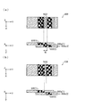
- FIG. 3 shows a part of the laminated structure in which the layer 5a (4) is laminated on the layer 5a (5).
- FIG. 3 (a) is a top view and FIG. 3 (b) is a diagram.
- FIG. 4 is a cross-sectional view taken along the arrow line showing a state where the laminate of (a) of 3 is cut along a cutting line BB ′.
- the shape of the XY plane of the layers 5a (4) and 5a (5) is a strip shape in FIG.
- the portions 53 of the colored layers of the stacked layers 5a (4) and 5a (5) overlap each other in the second colored region 53b.
- the first colored region 53a adjacent to the second colored region 53b in the portion 53 of each colored layer does not overlap any part of the portion 53 of the colored layer included in the stacked layers.
- the layer 5a (5) corresponding to the lower layer has a larger diameter than the layer 5a (4) corresponding to the upper layer, and accordingly, the portion 53 of the colored layer of the lower layer 5a (5) is higher in the upper layer 5a (4).
- the second colored region 53b on the inner peripheral side of the portion 53 of the colored layer of the lower layer 5a (5) overlaps with the second colored region 53b on the outer peripheral side of the portion 53 of the colored layer of the upper layer 5a (4). .
- the second colored region 53b is configured such that the discharge volume of the colored ink per unit volume is smaller than that of the first colored region 53a.
- the colored layers 3 are not seen until the two layers 5a (4) and 5a (5) are seen through the overlapping regions. It is configured to be visually recognized as exhibiting a desired color tone as a part of.
- the discharge volume of the colored ink per unit volume is adjusted so that the region where the second colored regions 53b overlap each other has the same color tone as the non-overlapped first colored region 53a. .
- the ratio of the discharge volume of the colored ink per unit volume of the first colored region 53a per layer the color ink per unit volume of the second colored region 53b.
- the ratio of the discharge volume is half (50%).
- the formation region is shifted in the direction in which the diameter 53 of the colored layer 53 of the lower layer 5 a (5) is larger than the portion 53 of the colored layer of the upper layer 5 a (4).
- the second colored region 53b on the outer peripheral side of the colored layer portion 53 of (5) does not overlap with the colored layer portion 53 of the upper layer 5a (4), but is laminated below the lower layer 5a (5). It overlaps with a portion 53 of the colored layer of the layer 5a (6).
- the second colored region 53b on the inner peripheral side of the colored layer portion 53 of the upper layer 5a (4) does not overlap with the colored layer portion 53 of the lower layer 5a (5), but is further above the upper layer 5a (4). Is superimposed on the second colored region 53b on the outer peripheral side of the layer 5a (3) stacked on the outer periphery.
- the discharge volume of the colored ink per unit volume of the second colored region 53b may be slightly smaller than the discharge volume of the colored ink per unit volume of the first colored region 53a.
- the sum of the discharge volumes of the colored ink in the two overlapping second colored regions 53b is obtained by dividing by the volume of the second colored region 53b per layer. It is preferable that the discharge volume of the colored ink per unit volume is equal to the discharge volume of the colored ink per unit volume of the first colored region 53a.
- the discharge volume of the colored ink per unit volume of the second colored region 53b is the same for all the layers 5a (4), 5a (5), and 5a (6), and the same for the first colored region 53a.
- the discharge volume of colored ink per unit volume is 50%.
- the second colored regions 53b that overlap vertically may have different discharge volumes of colored ink per unit volume.
- the ratio of the discharge volume of the color ink per unit volume is [30].
- the second colored region 53b with the ratio of the discharge volume of the colored ink per unit volume as [70] may be superimposed.
- the horizontal surface area H and the curved surface area R of the three-dimensional object 5 in which the second colored regions 53b in which the discharge volume of the colored ink per unit volume is smaller than the first colored region 53a are laminated are the colored layer. 3 does not cause a problem of the color tone described above, and the colored layer 3 is expressed in a desired color tone even when the surface of the three-dimensional object 5 is viewed from all directions of X, Y, and Z.
- the three-dimensional object 5 is in the order of the second transparent layer 4, the colored layer 3, the first transparent layer 2, and the light reflecting layer 1 from the surface layer side toward the center side.
- the color tone expressed by subtractive color mixture can be visually recognized.
- FIG. 1B shows a state in which a part 52 of the first transparent layer is overlapped with each other as a broken-line frame s1. Further, FIG. 1B also shows a state in which a part 51 of the light reflecting layer is partially overlapped in the upper and lower layers as a broken-line frame s2. In this way, not only the colored layer but also other layers can be superposed one on top of the other to realize a good three-dimensional object that does not cause color problems such as color loss from any direction. Can contribute.
- the discharge volume of the transparent ink per unit volume of the portion where the first transparent layer portions 52 are overlapped with each other is set to be the same per unit volume of the portion of the first transparent layer 52 where the portions 52 are not overlapped with each other. You may make it smaller than the discharge volume of transparent ink. Thereby, in the superposed part, it can contribute to realization of a favorable three-dimensional object, without producing a malfunction in a color tone.
- the light reflective ink ejection volume per unit volume of the portion where the portions 51 of the light reflecting layer overlap each other is set as the light reflection per unit volume of the portion of the portion 51 of the light reflecting layer which does not overlap each other. It may be smaller than the discharge volume of the functional ink.
- all of the colored layers 53 of all the layers constituting the horizontal plane area H and the curved surface area R have the second colored region 53b and the first colored region 53b along the inner direction (radial direction).
- One colored region 53a and a second colored region 53b are formed in this order.
- the present invention is not limited to this, and there is no first colored region 53a, and only the second colored region 53b is formed, and a part of the second colored region 53b is formed as the second colored region 53b of the upper layer. And a layer in a mode of overlapping the remaining portion with the second colored region 53b of the lower layer.
- the formation width of the second colored region 53b which includes the portion overlapping the second colored region 53b of the upper layer and the portion overlapping the second colored region 53b of the lower layer, 2w (w is the formation width of the overlapping portion in the upper and lower two layers as described above).
- the vertical plane area V shown in FIG. 1B is an area extending substantially perpendicular to the horizontal plane, and the layer 5a constituting the vertical plane area V In (7) to 5a (14), the portions 53 of the colored layers overlap in almost the entire region. Therefore, for the laminated region in which almost the entire region of the colored layer portion 53 needs to be superposed in this way, the discharge volume of the colored ink per unit volume of the entire region of the colored layer portion 53 is the second described above. It is made equal to the discharge volume of the colored ink per unit volume of the colored region 53b.
- the formation width of the portion 53 of the colored layer along the internal direction (radial direction) of the layers 5a (7) to 5a (14) is set to be the width of each of the layers 5a (7) to 5a (14).
- the thickness (d) is twice (2d) the thickness (d) along the stacking direction.
- the thickness (height) in the Z direction of each layer 5 a (1) is the precision of the shape required for the modeled object, the resolution and number of gradations of the colored layer 3, the size of the ink jet ink droplets, the inner side of the colored layer 3 It can be set as appropriate depending on the formation width along the direction, the number of stacked layers, and the like.
- the thickness of one layer 5a (1)... In the Z direction is in the range of 5 ⁇ m to 200 ⁇ m suitable for multicolor formation mainly by subtractive color mixing of the colored layer 3.
- a preferable range is 10 ⁇ m to 100 ⁇ m.
- a plurality of layers may be stacked with the same data, or larger ink droplets may be used. In that case, a reduction in data volume and an increase in modeling speed can be expected.
- the colored layer 3 may be ejected a plurality of times to form one layer with a plurality of ink droplets in the Z direction.
- the light reflecting layer 1 (a part 51 of the light reflecting layer), the first transparent layer 2 (a part 52 of the first transparent layer), the colored layer 3 (a part 53 of the colored layer), the second The transparent layer 4 (a part 54 of the second transparent layer) will be described.
- Light reflecting layer 1 (a part 51 of the light reflecting layer)
- the light reflection layer 1 (a part 51 of the light reflection layer) is a layer formed of white ink or light-reflective ink, and at least the surface of the light reflection layer 1 on the colored layer 3 side has the entire visible light region. It has light reflectivity that can reflect light.
- the light reflecting layer 1 (a portion 51 of the light reflecting layer) can be formed from an ink containing a metal powder or an ink containing a white pigment, but is preferably formed from a white ink.
- a white ink By forming from a white ink, the light which entered from the surface layer side of the molded article in the light reflection layer 1 can be favorably reflected, and coloring by subtractive color mixture can be realized.
- the thickness of the light reflecting layer 1 can be 5 ⁇ m to 200 ⁇ m.
- the thickness of the light reflection layer 1 here is the same as the width along the inner side direction (center side direction) from the outer peripheral end side of the part 51 of the light reflection layer included in the layer 5a.
- the present invention is not limited to this numerical range.
- the first transparent layer 2 (a part 52 of the first transparent layer) is formed from a transparent ink.
- the transparent ink may be any ink that can form a transparent layer having a light transmittance of 50% or more per unit thickness. If the light transmittance per unit thickness of the transparent layer is less than 50%, the light transmission is undesirably blocked, and the molded article cannot exhibit a desired color tone due to subtractive color mixing, which is not desirable.
- an ink having a light transmittance of 80% or more per unit thickness of the transparent layer is used, and an ink having a light transmittance of 90% or more per unit thickness of the transparent layer is more preferably used.
- the first transparent layer 2 (a part 52 of the first transparent layer) between the light reflecting layer 1 (a part 51 of the light reflecting layer) and the colored layer 3 (a part 53 of the colored layer). It is possible to avoid mixing the colored ink forming the colored layer 3 and the ink forming the light reflecting layer 1. Even if the colored ink that forms the colored layer is mixed with the transparent ink that forms the first transparent layer, the color of the colored layer 3 is not lost, and therefore, an undesirable change in color tone is not caused. Therefore, it is possible to realize a shaped article that exhibits a desired color tone (decoration) in the colored layer 3.
- the thickness of the first transparent layer 2 can be 5 ⁇ m to 20 ⁇ m.
- the thickness of the 1st transparent layer 2 here is the same as the width
- the present invention is not limited to this numerical range.
- Colored layer 3 (colored layer part 53)
- the ink used for forming the colored layer 3 (colored layer portion 53) includes a colored ink containing a colorant.
- the colored ink examples include yellow (Y), magenta (M), cyan (C), black (K), and light-colored inks, but are not limited thereto, and include red (R), green (G), blue (B), orange (Or), or the like may be added. It is also possible to use metallic, pearl and phosphor colors. One or more kinds of these colored inks may be used in order to express a desired color tone.
- the amount of the colored ink used for forming the first colored region 53a of the colored layer 3 (colored layer portion 53) varies depending on the desired (desired) color tone. Therefore, in the case of a light color tone with low density, the ink filling density of the first colored region 53a does not satisfy the predetermined ink filling density with only colored ink, and unevenness is formed at the height in the Z direction, In some cases, a recess having no colored ink is formed in the middle along the Y direction. In any case, inconvenient irregularities are generated in the shaped article formed by the lamination method as in this embodiment, which is not preferable. In particular, on the vertical modeling surface near the middle of the laminated structure shown in FIG.
- the ink is formed by the error diffusion method, so that one cross section of the colored layer 3 has a total of 4 drops, 2 ink drops vertically and horizontally.
- the number of colored inks is 4 drops at the maximum (maximum density) and 0 at the minimum (zero density, that is, white), so in the case of the minimum, a gap space of 4 drops is formed.
- the quality is greatly impaired from both the modeling surface and the color surface.
- the colored layer 3 (with the supplementary ink is used for the portion where the ink filling density of the first colored region 53a of the colored layer 3 (the colored layer portion 53) does not satisfy the predetermined ink filling density with only the colored ink.
- the ink filling density of the first colored region 53a of the colored layer portion 53) is compensated.
- 3 drops of supplementary ink when there is 1 drop of colored ink 1 drop of supplementary ink when there are 3 drops of colored ink, and supplementary ink when there is no colored ink 4 drops.
- the first colored region 53a of the colored layer 3 (the colored layer portion 53) is formed so that the total density (number of ink droplets) of the colored ink and the supplemental ink is constant.
- production of the dent mentioned above can be avoided and the shape of the solid object 5 can be modeled densely.
- the compensation amount and the compensation position (landing position) of the compensation ink can be determined by taking these into account. The determination can be made by the inkjet head device 10 or the control device 30 (FIG. 4) or other control means.
- the surface formed by the first colored region 53a of the colored layer 3 becomes flat, so that a glossy feeling can be given.
- the supplementary ink may be any ink that does not adversely affect the color tone to be exhibited by the first colored region 53a of the colored layer 3 (colored layer portion 53).
- the first transparent layer 2 first transparent layer 2
- the transparent ink used in the layer portion 52) and the second transparent layer 4 first transparent layer portion 54
- the thickness of the colored layer 3 can be, for example, 10 ⁇ m to 100 ⁇ m.
- the thickness of the colored layer 3 here is the same as the width along the center side direction from the outer peripheral end side of the portion 53 of the colored layer included in each layer 5a (2).
- this embodiment demonstrates based on the colored layer 3, this invention is not limited to a colored layer, There will be no restriction
- the second transparent layer 4 (a part 54 of the second transparent layer) is the first transparent layer 2 (of the first transparent layer). It is formed using the transparent ink described in the part 52).
- the second transparent layer 4 and the first transparent layer 2 may be formed using the same type of transparent ink, or may be formed using different types of transparent ink.
- the thickness of the second transparent layer 4 may be, for example, 10 ⁇ m or more, and the upper limit value can be appropriately changed according to the size of the outer shape of the three-dimensional object 5.
- the thickness of the second transparent layer 4 is the thickness of the second transparent layer portion 54 along the inner side direction from the outer peripheral end side of each layer 5a (1) including the second transparent layer portion 54. Same as width.
- the second transparent layer 4 not only has a function as a protective layer for the colored layer 3, but also enables the three-dimensional object 5 to be densely manufactured in the present invention (this embodiment) that employs a lamination method. It has an advantageous effect of making it. That is, if the colored layer 3 constitutes the outermost layer of the three-dimensional object 5, that is, if the part 53 of the colored layer is located at the end most in the layer 5a having the part 53 of the colored layer, There is a possibility that the colored layer 3 (a part 53 of the colored layer) cannot be formed with high accuracy.
- the second transparent layer 4 (a part 54 of the second transparent layer) is formed on the outermost layer of the three-dimensional object 5 as in the present embodiment, the colored layer 3 (a part 53 of the colored layer) is formed. Since it is formed with high accuracy, it can contribute to exhibiting a desired color tone.
- the colored layer 3 constitutes the outermost layer of the three-dimensional object 5
- the colored layer 3 is exposed, so that discoloration due to rubbing and fading due to ultraviolet rays are likely to occur.
- the second transparent layer 4 (a part 54 of the second transparent layer) is formed on the outermost layer of the three-dimensional object 5 as in the present embodiment, decolorization and fading can be prevented.
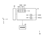
- FIG. 4 is a diagram illustrating a main configuration of the three-dimensional object modeling device of the present embodiment.
- the three-dimensional object formation apparatus 40 of the present embodiment includes an inkjet head device 10 (formation unit, second formation unit, third formation unit, fourth formation unit), an ultraviolet irradiation device 20, and a control device 30 (formation). Part, second formation part, third formation part, fourth formation part).
- Inkjet head device 10 On the lower surface of the inkjet head device 10 shown in FIG. 4, roughly three inkjet heads 11H to 13H are mounted. As shown in FIG. 4, the arrangement positions of the first inkjet head 11H, the second inkjet head 12H, and the third inkjet head 13H are shifted along the X direction. Further, as shown in FIG. 4, the first ink jet head 11H, the second ink jet head 12H, and the third ink jet head 13H are arranged at different positions along the Y direction. That is, the inkjet heads 11H to 13H are arranged in a so-called staggered arrangement.
- the first inkjet head 11H includes a cyan ink nozzle 10 (C) for discharging cyan ink, a magenta ink nozzle 10 (M) for discharging magenta ink, and a yellow ink nozzle 10 (Y for discharging yellow ink). ) And a black ink nozzle 10 (K) for discharging black ink.
- the order and number of the nozzles 10 (C), 10 (M), 10 (Y) and 10 (K) are not limited to those shown in FIG.
- the ink ejected from these nozzles is a colored ink used for forming the colored layer 3 (colored layer portion 53) shown in FIG.
- the second inkjet head 12H is provided with a white ink nozzle 10 (W) for discharging white ink (W).
- This white ink (W) is an ink used for forming the light reflecting layer 1 (a part 51 of the light reflecting layer 1) shown in FIG.
- the third inkjet head 13H is provided with a transparent ink nozzle 10 (CL) for discharging transparent ink (CL).
- the transparent ink (CL) includes a first transparent layer 2 (a portion 52 of the first transparent layer) shown in FIG. 1B and a second transparent layer shown in FIGS. 1A and 1B. Ink used to form layer 4 (second transparent layer portion 54).
- a nozzle for discharging the dedicated ink may be provided in combination with the other nozzle described above, or discharged from the other nozzle described above. Ink may be used.
- the inkjet head device 10 is provided so that the lower surface shown in FIG. 4 faces the forming surface of the forming table (the forming surface D of the forming table is shown in FIG. 6) or the formed layer. Further, the inkjet head device 10 can reciprocate in the X direction, and ejects ink during the movement. The movement is controlled by a control device 30 described later.
- the relative position between the inkjet head device 10 and the formation surface D only needs to change in a predetermined direction, and the inkjet head device 10 may move in a predetermined direction in the XYZ coordinate system.
- the surface D may be moved in a predetermined direction in the XYZ coordinate system.
- the ultraviolet irradiation device 20 has a light source that irradiates ultraviolet rays in order to cure the ultraviolet curable ink ejected from the inkjet head device 10.
- the ultraviolet irradiation device 20 is disposed in the vicinity of the inkjet head device 10 so that the ink ejected from the inkjet head device 10 can be irradiated with ultraviolet rays.
- the ultraviolet irradiation of the ultraviolet irradiation device 20 is controlled by a control unit (not shown).
- Control device 30 controls ink ejection from a specific nozzle of the inkjet head device 10, its ejection amount, and its ejection force based on the pattern data.
- the pattern data is data in which the appearance / interior design, mechanism, etc. of the three-dimensional object 5 that is a modeling object is converted into data by three-dimensional CAD, and then the data is sliced by a computer and patterned into a multilayer type. is there.
- the ejection is performed by controlling the voltage application to the inkjet head device 10 from a power source (not shown), and the ejection amount and the ejection force are controlled by controlling the voltage application amount to the nozzle of the inkjet head device 10 that ejects ink. By doing. Further, the control device 30 also controls the movement of the inkjet head device 10 as described above.
- control apparatus 30 controls the inkjet head apparatus 10, and the solid object 5 shown in FIG. 1 is modeled by the lamination
- the control device 30 is formed by controlling the inkjet head device 10.
- FIG. 5 is a specific example of FIG. 3 and shows a part of the XY plane configuration of the layer 5a (4) and the layer 5a (5) of the three-dimensional object 5.
- the shape of the XY plane of the layers 5a (4) and 5a (5) is a strip shape, and only the characteristic portions are clearly shown.
- the second colored region 53b adjacent to the first colored region 53a has a colored ink deposition region A and a transparent ink deposition region B.
- the colored ink accumulation area A of the second colored area 53b has the same configuration in the Z direction as the colored ink accumulation area of the first colored area 53a.
- the colored ink accumulation region A is formed in a shape in which a plurality of triangles are arranged in the X direction on the XY plane shown in FIG.
- the first colored region 53a and the second colored region 53b are expressed with the same density for the sake of convenience, but the number of ink droplets of the colored ink in this region and the number corresponding to the density of the image data, Place it at a position according to the data.
- the transparent ink accumulation area B of the second colored area 53b is an area where only transparent ink is accumulated, and has a shape symmetrical to the colored ink accumulation area A by arranging a plurality of triangles in the X direction on the XY plane shown in FIG. have.
- the transparent ink that forms the transparent ink accumulation region B is ejected from the transparent ink nozzle 10 (CL) of the inkjet head device 10 (FIG. 4).
- the ink accumulation amount constituting the colored ink accumulation region A occupies half of the ink accumulation amount constituting the second coloring region 53b, and the ink accumulation amount constituting the transparent ink accumulation region B is equal to the second coloring region. It accounts for the other half of 53b. That is, in the XY plane, the discharge volume of the colored ink per unit volume of the second colored region 53b is half of the discharge volume of the colored ink per unit volume of the first colored region 53a.
- the control device 30 realizes the colored ink accumulation region A and the transparent ink accumulation region B having the shapes shown in FIG. 5 by controlling the discharge of various inks from the inkjet head device 10.
- control device 30 forms the colored layer of the lower layer 5a (5) when the upper layer 5a (4) is laminated on the lower layer 5a (5) after forming the portion 53 of the colored layer of the lower layer 5a (5).
- the second colored region 53b of the portion 53 of the colored layer of the upper layer 5a (4) is superimposed on the second colored region 53b of the portion 53.
- the control device 30 forms the transparent ink deposition region B on the colored ink deposition region A of the second colored region 53b of the lower layer 5a (5), and the second colored region 53b of the lower layer 5a (5).
- a colored ink accumulation area A is formed on the transparent ink accumulation area B of the first ink.
- the transparent ink deposition region B and the colored ink deposition region A are formed so as to be reversed, whereby coloring when the upper and lower layers of the overlapping region w are seen through from above.
- the density of the ink becomes equal to the density of the colored ink in the first colored region 53a.
- the formation width of the colored layer portion 53 along the inner direction (radial direction) of the layer is larger than twice the formation width (w) of the overlapping region (> 2w).
- an excellent three-dimensional object 5 that does not have the color tone defects described above in the horizontal surface area H and the curved surface area R of the colored layer 3 is formed. Can do.
- the portions 53 of the colored layers are formed with each other. Are superimposed in almost the entire region.
- the discharge volume of the colored ink per unit volume of the entire region of the portion 53 of the colored layer is set to the same per unit volume of the second colored region 53b described above. The discharge volume of the colored ink is made equal.
- a portion 53 of the colored layers of the layers 5a (7) to 5a (14) constituting the vertical surface area V of the three-dimensional object 5 forms the colored ink deposition region A and the transparent ink deposition region B having the shapes shown in FIG. To do.
- the concentration of the colored ink when the overlapping portion is seen through the inside of the model is colored in the first colored region 53a. It becomes equal to the ink density.
- the formation width of the colored layer portion 53 along the internal direction (radial direction) of the layers 5a (7) to 5a (14) is The thickness (d) of each layer 5a (7) to 5a (14) in the stacking direction is twice (2d).
- the colored layer portion 53 of the layers 5a (7) to 5a (14) is configured such that the discharge volume of the colored ink per unit volume is smaller than that of the first colored region 53a. 2), the color tone is not unduly thinned.
- the control device 30 may be realized by a logic circuit (hardware) formed in an integrated circuit (IC chip) or the like, or may be realized by software using a CPU (Central Processing Unit).
- the control device 30 includes a CPU that executes instructions of a program that is software that realizes each function, a ROM (Read Only Memory) in which the program and various data are recorded so as to be readable by a computer (or CPU)
- a storage device (these are referred to as “recording media”), a RAM (Random Access Memory) for expanding the program, and the like are provided.
- the objective of this invention is achieved when a computer (or CPU) reads the said program from the said recording medium and runs it.
- a “non-temporary tangible medium” such as a tape, a disk, a card, a semiconductor memory, a programmable logic circuit, or the like can be used.
- the program may be supplied to the computer via an arbitrary transmission medium (such as a communication network or a broadcast wave) that can transmit the program.
- the present invention can also be realized in the form of a data signal embedded in a carrier wave in which the program is embodied by electronic transmission.
- the superposition is performed as the portion 53 of the colored layer of each of the layers with respect to the horizontal plane area H and the curved plane area R.
- the overlapping second colored region 53b is more per unit volume than the first colored region 53a.
- the colored ink is formed so as to have a small discharge volume (forming step).
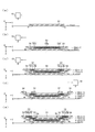
- FIG. 6 is a cross-sectional view schematically illustrating a process of modeling (manufacturing) the entire configuration of the three-dimensional object 5 of the present embodiment, and corresponds to the horizontal plane area H and the curved surface area R in FIG.
- region of the solid object 5 is shown.
- the lowest layer 5a (described as the nth layer 5a (n)) is formed on the forming surface D of the forming table which is a modeling stage.
- the transparent ink is ejected from the ink-jet head device 10 at a predetermined timing by using an ink-jet method, and the transparent ink is irradiated with ultraviolet rays and cured.
- the n-th layer 5a (n) consisting of only a part 54 of the second transparent layer is formed.
- an overhang portion 4h in which the diameter of the layer gradually increases as it goes in the stacking direction is formed at the outer peripheral end of the nth layer 5a (n). This overhang portion 4h is formed.
- an ink jet head may be added to the ink jet head device 10 to form a support layer on the outside of the shaped object.
- the (n-1) th layer 5a (n-1) is formed on the nth layer 5a (n).
- the inkjet head device 10 moves above the formed nth layer 5a (n) and ejects ink at a predetermined timing.
- a part of the second transparent layer is included so as to include the part 53 of the colored layer in the central part and surround the periphery of the part 53 of the colored layer.
- An n-1th layer 5a (n-1) including 54 is formed.
- the first colored region 53a and the second colored region 53b described above are formed in a portion 53 of the colored layer.
- the colored layer portion 53 and the second transparent layer portion 54 may be formed in parallel, or one of the colored layer portion 53 and the second transparent layer portion 54 is formed first, Thereafter, the other may be formed.
- the (n-2) th layer 5a (n-2) is formed on the (n-1) th layer 5a (n-1).
- the inkjet head device 10 moves above the already formed (n-1) th layer 5a (n-1), and has a predetermined timing.
- Ink is discharged to cure the ink by ultraviolet irradiation.
- the n-2th layer 5a (n-2) includes a first transparent layer portion 52, a colored layer portion 53, and a second transparent layer from the central portion to the end portion in the radial direction of the layer. Are formed so as to include a part 54 in this order.
- the first colored region 53a and the second colored region 53b described above are formed in the portion 53 of the colored layer, and the second colored region 53b is the lower layer of the (n ⁇ 1) th layer 5a (n ⁇ 1).
- the formation position of the second colored region 53b is controlled so as to overlap the second colored region 53b.
- the first transparent layer portion 52, the colored layer portion 53, and the second transparent layer portion 54 are arranged in parallel.
- the colored layer portion 53 may be formed after the first transparent layer portion 52 and the second transparent layer portion 54 are first formed.
- the n-3th layer 5a (n-3) is formed on the n-2th layer 5a (n-2).
- the step of forming (manufacturing) the n-3th layer 5a (n-3) first, as shown in FIG. 6D, the formed n-2th layer 5a (n-2)
- the inkjet head device 10 moves upward, ejects transparent ink at a predetermined timing, and cures the transparent ink by ultraviolet irradiation, whereby the first transparent layer portion 52 and the second transparent layer portion 54. Form.
- the overhang portion 4h is formed in the portion 54 of the second transparent layer by the method described above. Then, as shown in FIG.
- a part 51 of the light reflecting layer and a part 53 of the colored layer are formed. Also in this case, the first colored region 53a and the second colored region 53b described above are formed in the portion 53 of the colored layer, and the second colored region 53b is the lower layer of the n-2th layer 5a (n-2). ) To control the formation position of the second colored region 53b so as to overlap the second colored region 53b.
- n-3th layer 5a (n-3) By forming (manufacturing) the n-3th layer 5a (n-3), a part 51 of the light reflecting layer and a part of the first transparent layer are formed from the central part to the end part in the radial direction of the layer. 52, a colored layer portion 53, and a second transparent layer portion 54 in this order, the n-3th layer 5a (n-3).
- the step of forming the first transparent layer portion 52 and the second transparent layer portion 54 are formed.
- the process of forming is performed.
- a colored layer portion 53 is formed between the first transparent layer portion 52 and the second transparent layer portion 54, and the light reflecting layer. Part 51 of the substrate. Accordingly, when the second transparent layer portion 54 forms the colored layer portion 53, the second transparent layer portion 54 functions as an outer moat for the ink pool constituting the colored layer portion 53. There is no risk of undesirably spreading and the portion 53 of the colored layer can be formed with high accuracy.
- a part 52s of the portion 52 of the first transparent layer is replaced with the lower layer n-2th layer 5a (n-2).
- a part 52 of the first transparent layer is partially overlapped as a broken-line frame s1.
- FIG. 1B also shows a state in which a part 51 of the light reflecting layer is overlapped with each other in the upper and lower layers as a broken-line frame s ⁇ b> 2. .
- the colored layer 3 but also other layers can be partially overlapped with each other to contribute to the realization of a good three-dimensional object that does not cause a problem in color tone from any direction. it can.
- the colored layer forming ink composed of the colored ink and the supplemental ink is ejected so that the total amount of both inks is constant, UV cure.
- the horizontal surface area H and the curved surface area R of the three-dimensional object 5 shown in FIG. 1B can be manufactured.
- the colored layer portion 53 is formed only from the second colored region 53b so that the colored layer portions 53 overlap each other in substantially the entire region. That's fine.
- a part of the colored layers of each layer is overlapped and formed. can do. If a colored layer is formed by linking a part of the colored layer in the stacking direction without overlapping a part of the colored layer of each layer, the position of forming a part of the colored layer of each layer is highly accurate (careful). Therefore, it is difficult to quickly form a three-dimensional object. However, according to this embodiment, since a part of colored layers of each layer is overlapped, it can contribute to rapid modeling of a three-dimensional object.
- the color tone of the superimposed portion is adjusted so that a desired color tone can be expressed for the first time by superimposition, a good three-dimensional object that does not cause a color tone defect and that does not have a color tone defect is provided. Can do.
- FIG. 7 is a view showing another aspect of the second colored region 53b, and shows a part of the XY plane configuration of the layer 5a (4) and the layer 5a (5) as in FIG.
- a colored ink accumulation area A and a transparent ink accumulation area B are formed in a striped pattern alternately arranged in the X-axis direction, and each colored ink accumulation area A and each transparent ink accumulation area B is formed.
- This elongated shape is a size in which a plurality of ink droplets ejected from the nozzles of the inkjet head device 10 (FIG. 4) are formed in a line, as shown in the enlarged view of the dotted circle in FIG. It is.
- the inkjet head device 10 (FIG. 4) capable of ejecting the same color ink from a plurality of nozzles is used, the above-described elongated shape is obtained from the nozzles of even lines while moving the inkjet head device 10 in the Y-axis direction. It can be formed by continuously ejecting ink for forming the colored ink accumulation region A and continuously ejecting transparent ink for forming the transparent ink accumulation region B from the nozzles of odd-numbered lines. It can be said that this aspect is an X-direction (line) interlace method that extends over two adjacent upper and lower layers.
- This discharge mode is performed by controlling the inkjet head device 10 by the control device 30 (FIG. 4).
- the transparent ink deposited region B of the layer 5a (5) is superimposed on the colored ink deposited region A of the layer 5a (4).
- the colored ink deposition region A of the layer 5a (5) is superimposed on the transparent ink deposition region B of the layer 5a (4).
- FIG. 8 shows still another aspect of the colored ink accumulation area A and the transparent ink accumulation area B of the second coloring area 53b.
- a colored ink accumulation area A and a transparent ink accumulation area B are formed in a striped pattern alternately arranged in the Y-axis direction, and each colored ink accumulation area A and each transparent ink accumulation area B is It has an elongated shape and extends in the X-axis direction.
- This elongated shape is a size formed by arranging a plurality of ink droplets ejected from the nozzles of the inkjet head device 10 (FIG. 4) in a line, as in FIG.
- This elongated shape can be formed by ejecting ink continuously while moving the inkjet head device 10 (FIG. 4) in the X-axis direction. It can be said that this mode is a Y-direction (line) interlace method that straddles two adjacent upper and lower layers.
- the layer 5 a is formed on the colored ink accumulation region A of the layer 5 a (4).
- the upper and lower layers are adjusted so that the transparent ink deposition region B of (5) overlaps and the colored ink deposition region A of layer 5a (5) overlaps the transparent ink deposition region B of layer 5a (4). .
- the gap transparent ink accumulation region B between the colored ink accumulation region A and the colored ink accumulation region A of the layer 5a (4). Therefore, the colored ink accumulation region A of the layer 5a (5) can be seen, and the entire second colored region 53b is visually recognized in the same color tone as the first colored region 53a.
- FIG. 9 is a graph showing the relationship between the number of pixels on which colored ink is to be recorded and the position.
- the pixel on which the colored ink is to be recorded is a pixel at a position where the colored ink is to be disposed, and the colored ink or the supplementary ink is ejected to the pixel in accordance with the image data.
- the gradient is reversed in the second colored region 53b of the layer 5a (5) overlapping the second colored region 53b of the layer 5a (4). Accordingly, when the layers 5a (4) and 5a (5) are seen through from above while the second colored regions 53b are superimposed on each other in the layers 5a (4) and 5a (5), the overlapping regions are It is visually recognized with the same color tone as the first colored region 53a.
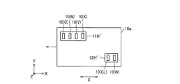
- the three-dimensional object 5 is manufactured using the inkjet head device 10 shown in FIG. 4, but the inkjet head device to be used is not limited to these, It is also possible to use the inkjet head devices shown in FIGS. 10 to 13 respectively.
- two inkjet heads 11H ′ and 12H ′ are mounted on the lower surface of the inkjet head device 10a. As shown in FIG. 10, the first inkjet head 11H ′ and the second inkjet head 12H ′ are displaced in the arrangement direction along the X direction and are displaced in the Y direction. .
- FIG. 11 is a view showing a modified example of the ink jet head device.
- a cyan ink nozzle 10 (C) On the lower surface of the inkjet head device 10b shown in FIG. 11, a cyan ink nozzle 10 (C), a magenta ink nozzle 10 (M), a yellow ink nozzle 10 (Y), and a black ink nozzle 10 (K ), White ink nozzles 10 (W), and transparent ink nozzles 10 (CL) are arranged in this order in the X direction.
- C cyan ink nozzle 10
- M magenta ink nozzle 10
- Y yellow ink nozzle 10
- K black ink nozzle 10
- W White ink nozzles 10
- CL transparent ink nozzles 10
- FIG. 12 is a view showing still another modified example of the inkjet head device.
- a white ink nozzle 10 (W) On the lower surface of the inkjet head device 10c shown in FIG. 12, a white ink nozzle 10 (W), a transparent ink nozzle 10 (CL), a yellow ink nozzle 10 (Y), and a magenta ink nozzle 10 (M ),
- the cyan ink nozzle 10 (C), the black ink nozzle 10 (K), the transparent ink nozzle 10 (CL), and the white ink nozzle 10 (W) in this order in the X direction. They are arranged.
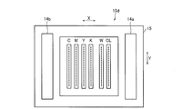
- FIG. 13 is a view showing still another modified example of the ink jet head device.
- An inkjet head device 10 d shown in FIG. 13 includes a carriage 15 that can reciprocate along the X axis, a plurality of nozzle rows mounted on the carriage 15, and ultraviolet irradiators 14 a and 14 b mounted on the carriage 15. .
- the carriage 15 is moved in the X direction, and ultraviolet curable ink is ejected from the nozzle row, and scanning is performed to irradiate ultraviolet rays from the ultraviolet irradiators 14a and 14b.
- the plurality of nozzle rows are provided along the X direction as shown in FIG.
- the cyan ink nozzle row C, the magenta ink nozzle row M, and the yellow ink are arranged from the left side to the right side in the X direction.
- the nozzle row Y for black, the nozzle row K for black ink, the nozzle row W for white ink, and the nozzle row CL for transparent ink are arranged in this order. Since each of the plurality of nozzle rows is mounted on the carriage 15, it is possible to eject ultraviolet curable ink when moving in the X direction as the carriage 15 moves.
- FIG. 11 since all the nozzles are arranged in the X direction, it is possible to form a layer by ejecting all ink in one layer by a single movement in the X direction. .
- ultraviolet irradiation is performed simultaneously with ink ejection by a single movement in the X direction, so that further curing in the case of ultraviolet curable ink can be performed at the same timing as ejection.
- the three-dimensional object modeling apparatus 40 includes a forming unit (inkjet head device 10 and control device 30) that stacks layers formed from colored ink or transparent ink, and the forming unit (inkjet head device 10). And the control device 30), the overlapping region (second colored region 53 b) of the layers formed by the same ink (ink for forming the colored layer part 53) is formed by the overlapping region (second colored region 53 b) formed by the ink.
- the discharge volume of ink per unit volume is smaller than the region (first colored region 53a) other than the colored region 53b) (the first colored region 53a) where the layers formed by the ink do not overlap each other (first colored region 53a). It is characterized by forming.
- the portions formed by the same ink are overlapped, if the ink is an ink containing a colored ink, the colored portions in the stacking direction are not overlapped without overlapping the colored portions of each layer.
- the ink is an ink containing a colored ink
- the colored portions in the stacking direction are not overlapped without overlapping the colored portions of each layer.
- the portions formed by the same ink are overlapped, for example, as described in the above-described embodiment, a part of the colored portion (a portion 53 of the colored layer) of each layer 5a (2). By doing so, there is no possibility that a gap is formed between some of the colored portions (colored layer portion 53) included in the upper and lower layers 5a (2).
- the overlapping area (second colored area 53b) has a smaller discharge volume of colored ink per unit volume than the non-overlapping area (first colored area 53a). Formed.
- the color tone of the superimposed region (second colored region 53b) is adjusted so that a desired color tone can be expressed only after the color tone is superimposed. As a result, there is no inconvenience that the color tone becomes undesirably dark due to the superimposition, and it is possible to provide a good three-dimensional object 5 that is quick and has no inconvenience in the color tone.
- the three-dimensional object formation apparatus 40 includes a layer 5a in which the overlapping region includes a colored portion (a colored layer portion 53) formed from an ink containing a colored ink. (2)... Is a region in which the layers overlap each other, and the forming unit (inkjet head device 10 and control device 30) is used as the colored portion (colored layer portion 53) of each of the layers 5a (2).
- a region (second colored region 53b) and an adjacent region (first colored region 53a) adjacent to the overlapping region in a direction perpendicular to the stacking direction are formed, and the forming unit includes the overlapping region (second colored region).
- the region 53b) is formed so that the discharge volume of the colored ink per unit volume is smaller than the adjacent region (first colored region 53a) (horizontal plane area H, curved surface area R).
- the colored portions (parts 53 of the colored layer) of each layer 5a (2) when the three-dimensional object 5 is formed in the stacking method, the colored portions (parts 53 of the colored layer) of each layer 5a (2). If the colored layer is formed by connecting the colored portions in the stacking direction without overlapping the colored portions of each layer, the position of forming the colored portion of each layer must be adjusted with high precision (carefully). Therefore, it is difficult to quickly model a three-dimensional object.
- the colored portions (the colored layer portion 53) of each layer 5a (2)... Are overlapped with each other, which can contribute to rapid modeling of the three-dimensional object 5. .
- the discharge volume of the colored ink per unit volume is smaller in the overlapping region (second colored region 53b) than in the adjacent region (first colored region 53a).
- the color tone of the superimposed region (second colored region 53b) is adjusted so that a desired color tone can be expressed only after the color tone is superimposed.
- the color tone becomes undesirably dark due to the superimposition, and it is possible to provide a good three-dimensional object 5 that is quick and has no inconvenience in the color tone.
- the three-dimensional object formation device 40 is configured so that the forming unit (the inkjet head device 10 and the control device 30) defines the overlapping region (second colored region 53b). It is formed by discharging colored ink and transparent ink.
- the three-dimensional object formation device 40 includes the above-described formation unit (inkjet head device 10 and control device 30) in which the upper and lower two layers 5a (2) are stacked. ... the total volume of the discharge volumes of the colored ink per unit volume of the overlapping area (second colored area 53b) and the same of the adjacent area (first colored area 53a) of one layer 5a (2).
- the overlapping region (second colored region 53b) is formed so that the discharge volume of the colored ink per unit volume is equal.
- region 53b) becomes a desired color tone only after superimposing (it is not until superimposition, the said adjacent area
- the three-dimensional object formation device 40 is configured so that the formation unit (the inkjet head device 10 and the control device 30) includes the first layer 5a (2).
- the overlapping region (second colored region 53b) and the second overlapping region (second colored region 53b) are formed, and the forming unit is configured to stack the two layers 5a (2).
- the first overlapping region (second colored region 53b) of the layer stacked below is superimposed on the second overlapping region (second colored region 53b) of the layer stacked above or above Is superimposed on the first overlapping region (second colored region 53b) of the layer stacked on the substrate.
- the colored layer 3 formed by linking colored portions can be formed to be inclined with respect to the stacking direction.
- the three-dimensional object formation device 40 is configured so that the forming unit (the inkjet head device 10 and the control device 30) has an internal direction (diameter) of each layer.
- the width of formation of the first overlapping region (second colored region 53b) and the width of formation of the second overlapping region (second colored region 53b) are equal to each other.
- the formation width is w
- the formation width of the colored portion (colored layer portion 53) is 2 w or more.
- the three-dimensional object formation apparatus 40 includes a second forming unit that forms overlapping regions of layers formed by the same ink over the entire region of each layer (
- the ink jet head device 10 and the control device 30 are further provided (vertical surface area V), and the second forming portion (the ink jet head device 10 and the control device 30) is arranged in the entire region (layers 5a (7) to 5a (14).
- the discharge volume of the ink per unit volume of the colored layer portion 53) is equal to the unit volume of the overlapping area (second colored area 53b) formed by the forming unit (inkjet head device 10 and control device 30). It is formed so as to be equal to the discharge volume of the ink (colored ink).
- the 2nd formation part (the inkjet head apparatus 10 and the control apparatus 30) combines the color tone of the said all area
- the area is adjusted so that a desired color tone can be expressed only after overlapping. As a result, there is no problem that the color tone becomes undesirably dark due to the superimposition.
- the superposition can contribute to the improvement of the modeling speed as compared with the case where the superposition is not performed.
- the three-dimensional object formation apparatus 40 includes the second forming unit (the inkjet head device 10 and the control device 30) in which the layers 5a (7) to 5a ( 14)
- the formation width of the entire region (the colored layer portion 53 of the layers 5a (7) to 5a (14)) along the internal direction (radial direction) of 14) is set to the layer 5a (7 ) To 5a (14) twice the thickness (d) (2d).
- the overlapping region (second colored region 53b) formed by the forming unit (inkjet head device 10 and control device 30) and the discharge volume of ink (colored ink) per unit volume are configured to be equal. Even if it is a case where all the said area
- the three-dimensional object formation apparatus 40 includes at least two layers 5a (3)... In the layer 5a rather than the colored portion (colored layer portion 53). Is provided with a third forming portion (inkjet head device 10 and control device 30) for forming a transparent portion (a portion 52 of the first transparent layer) using a transparent ink, and the third forming portion ( The inkjet head device 10 and the control device 30) are arranged on a part of the transparent portion (a part 52 of the first transparent layer) of the layer having the transparent part (a part 52 of the first transparent layer). A part of the transparent portion (a portion 52 of the first transparent layer) of the layer to be laminated is overlapped.
- the three-dimensional object modeling apparatus 40 which concerns on one form of this invention is at least 2 of the said layers 5a (3) ... which have the said transparent part (a part 52 of a 1st transparent layer).
- a light reflecting portion (a portion 51 of the light reflecting layer) is formed using an ink having light reflectivity inside the layer from the transparent portion (a portion 52 of the first transparent layer).
- a fourth forming unit (inkjet head device 10 and control device 30) is provided, and the fourth forming unit (inkjet head device 10 and control device 30) has the light reflecting portion (a portion 51 of the light reflecting layer).
- a part of the light reflecting portion (a portion 51 of the light reflecting layer) of the layer 5a laminated on the layer 5a is superimposed on a part of the light reflecting portion (a portion 51 of the light reflecting layer) of the layer 5a.
- molding method which concerns on one form of this invention is equipped with the formation process which laminates
- the overlapping region (second colored region 53b) of the layers formed by the ink) is a region (first colored region 53a) other than the overlapping region (second colored region 53b) formed by the ink, It is characterized in that the ink discharge volume per unit volume is smaller than the area where the layers formed by ink do not overlap (the first colored area 53a).
- the colored portions formed by the same ink are overlapped, if the ink is an ink containing a colored ink, the colored portions in the stacking direction are not overlapped without overlapping the colored portions of each layer.
- the position where the colored portion of each layer is to be formed must be adjusted with high accuracy (careful), so that it is difficult to quickly model a three-dimensional object.
- the colored portions (the colored layer portion 53) of each layer 5a (2)... are overlapped with each other, which can contribute to rapid modeling of the three-dimensional object 5. .
- the portions formed by the same ink are overlapped, for example, as described in the above-described embodiment, a part of the colored portion (a portion 53 of the colored layer) of each layer 5a (2). If this is the case, there is no possibility that a gap is generated between some of the colored portions (colored layer portion 53) included in the upper and lower layers 5a (2).
- the overlapping area (second colored area 53b) has a smaller discharge volume of colored ink per unit volume than the non-overlapped area (first colored area 53a).
- the color tone of the superimposed region (second colored region 53b) is adjusted so that a desired color tone can be expressed only after the color tone is superimposed.
- the color tone becomes undesirably dark due to the superimposition, and it is possible to provide a good three-dimensional object 5 that is quick and has no inconvenience in the color tone.
- the three-dimensional object 5 is formed by stacking layers formed from colored ink or transparent ink, and the layers formed by the same ink (ink for forming a portion 53 of the colored layer) overlap each other.
- the region (second colored region 53b) is a region (first colored region 53a) other than the overlapping region (second colored region 53b) formed by the ink, and the layers formed by the ink do not overlap each other.
- the ink discharge volume per unit volume is smaller than the area (first colored area 53a).
- the present invention can be used for any three-dimensional object forming apparatus that forms a three-dimensional object, such as a three-dimensional object vending machine that automatically forms and sells a three-dimensional object.
Landscapes
- Engineering & Computer Science (AREA)
- Chemical & Material Sciences (AREA)
- Materials Engineering (AREA)
- Manufacturing & Machinery (AREA)
- Physics & Mathematics (AREA)
- Mechanical Engineering (AREA)
- Optics & Photonics (AREA)
- Multimedia (AREA)
- Signal Processing (AREA)
Abstract
所望のカラー加飾を呈する立体物を提供する。 造形される立体物5は、層5a(4)、5a(5)同士の第2着色領域53bを重畳させ、この第2着色領域53bは、隣接する第1着色領域53aよりも、単位容積あたりの着色インクの吐出容積が小さい。
Description
本発明は、立体物造形装置および立体物造形方法、並びに立体物に関し、より詳細には、インクを堆積させて層を形成し、該層を積層することによって立体造形をおこなう立体物造形装置および立体物造形方法、並びに立体物に関する。
三次元の立体物を造形する手法としては、特許文献1にあるようなインクジェット法のほか、溶融物堆積法(FDM:Fused Deposition Modeling)、シート積層法、インクジェットバインダ法、光造形法(SL:Stereo Lithography)、粉末焼結法(SLS:Selective Laser Sintering)などが知られている。
中でも、インクジェット法として、3Dプリンターによって紫外線硬化性樹脂を噴射しパターンを積層する方法が多用されている。この方法は、最終製品の外観内観のデザイン・機構等を三次元CADによってデータ化した後、コンピュータによって該データをスライスして薄板を重ね合わせるような多層型のパターンデータを作成し、紫外線硬化性樹脂をパターンデータに則してヘッドより噴射して積層することにより立体物を製造する。
また、このような手法を用いて造形した立体物に対して、加飾(模様や色)を施すことも知られている。
従来周知のインクジェット法による立体造形に関して、本願発明者が、造形用のインク、および加飾用のインク(例えばイエロー、マゼンタ、シアン、ブラック等の着色インク)をインクジェット法によって吐出してカラー加飾された立体物を積層方式で造形してみると、カラー加飾に不具合が生じる場合があることがわかった。
具体的には、積層方向に隣り合う上下の層に関して、各層に形成されているカラー加飾部分同士が重畳すると、重畳部分が所望の色調よりも濃く視認されてしまうという問題が生じる。また、これとは反対に、各層に形成されているカラー加飾部分同士が離間していると、上層のカラー加飾部分と下層のカラー加飾部分との境界に色抜けが生じているように見える場合がある。その結果、地形を縮小したジオラマ等を造形した場合に、等高線状の線となり、画質を損なうことになる。これら、重畳や色抜けの寸法は僅か数ミクロンの幅でも視認される。3Dプリンターは三次元方向の走査の一部が機械的走査で行われており、且つインクジェットでのインク滴の飛翔方向精度からも、数ミクロン以下の位置精度のばらつきに抑えるのは困難である。
そこで、本発明は、上記課題に鑑みてなされたものであり、所望のカラー加飾を呈する立体物を造形する立体物造形装置および立体物造形方法、並びに立体物を提供することを目的とする。
上記の課題を解決するために、本発明に係る立体物造形装置は、着色インクまたは透明インクから形成された層を積層する形成部を備え、上記形成部は、同じインクによって形成する層同士の重畳領域を、該インクによって形成する該重畳領域以外の領域であって該インクによって形成する層同士が重畳しない領域よりも、単位容積あたりの該インクの吐出容積が小さくなるように形成することを特徴としている。
該インクを、着色インクを含むインクとするならば、仮に、各層の着色部分を重畳させずに積層方向に着色部分を連ならせて着色層を形成する場合には、各層の着色部分を形成する位置を高精度に調整しなければならないため、立体物を迅速に造形することが困難である。しかしながら、本発明の上記の構成によれば、同じインクによって形成する部分を重畳させるので、立体物の迅速な造形に寄与することができる。
また、同じインクによって形成する部分を重畳させているので、例えば、上述のような色抜けもない。
また、本発明の上記の構成によれば、その重畳領域を、上記重畳しない領域よりも単位容積あたりの着色インクの吐出容積が小さくなるように形成する。例えば、重畳領域の色調を、重畳して初めて所望の色調が表現できるように調整する。これにより、重畳したことによって色調が不都合に濃くなるような不具合が生じることがなく、迅速且つ色調に不具合が無い良好な立体物を提供することができる。
また、本発明に係る立体物造形装置の一形態は、上記の構成に加えて、上記重畳領域は、着色インクを含むインクから形成された着色部分同士が重畳する領域であり、上記形成部は、各上記層の上記着色部分として、上記重畳領域と、積層方向に対して垂直方向に該重畳領域と隣接した隣接領域とを形成し、上記形成部は、上記重畳領域を、上記隣接領域よりも単位容積あたりの着色インクの吐出容積が小さくなるように形成する。
上記の構成によれば、積層方式において立体物を造形するにあたって、各層の着色部分を重畳させて形成する。仮に、各層の着色部分を重畳させずに積層方向に着色部分を連ならせて着色層を形成する場合には、各層の着色部分を形成する位置を高精度(慎重)に調整しなければならないため、立体物を迅速に造形することが困難である。しかしながら、本発明の上記の構成によれば、各層の着色部分の一部同士を重畳させるので、立体物の迅速な造形に寄与することができる。
また、各層の着色部分の一部同士を重畳させていれば、上下の層に含まれている着色部分の一部同士の間に隙間が生じて色抜けのように見える虞もない。
また、上記の構成では、重畳領域を隣接領域よりも単位容積あたりの着色インクの吐出容積が小さくなるように形成する。例えば、重畳領域の色調を、重畳して初めて所望の色調が表現できるように調整する。これにより、重畳したことによって色調が不都合に濃くなるような不具合が生じることがなく、迅速且つ色調に不具合が無い良好な立体物を提供することができる。
また、本発明に係る立体物造形装置の一形態は、上記の構成に加えて、上記形成部が、上記重畳領域を、着色インクおよび透明インクを吐出して形成する。
また、本発明に係る立体物造形装置の一形態は、上記の構成に加えて、上記形成部が、積層された上下2つの上記層の上記重畳領域の単位容積あたりの着色インクの吐出容積同士の合計容積と、1つの上記層の上記隣接領域の同単位容積あたりの着色インクの吐出容積とが等しくなるように、上記重畳領域を形成する。
上記の構成によれば、重畳領域の色調が、重畳して初めて所望の色調(1つの層の上記隣接領域の色調)となる。これにより、重畳したことによって色調が不都合に濃くなるような不具合が生じることがなく、迅速且つ色調に不具合が無い良好な立体物を提供することができる。
また、本発明に係る立体物造形装置の一形態は、上記の構成に加えて、上記形成部が、各上記層において、第1の上記重畳領域と、第2の上記重畳領域とを形成し、上記形成部は、積層される2つの上記層について、下に積層される上記層の上記第1の重畳領域を、上に積層される上記層の上記第2の重畳領域に重畳させるか、上に積層される上記層の上記第1の重畳領域に重畳させる。
上記の構成によれば、着色部分同士が連なって形成される着色層を、積層方向に対して傾斜させて形成することができる。
また、本発明に係る立体物造形装置の一形態は、上記の構成に加えて、上記形成部は、各上記層において、該層の内部方向に沿った、上記第1の重畳領域の形成幅と、上記第2の重畳領域の形成幅とを等しく形成し、且つ、これら各該形成幅をwとした場合、上記1つの層における、上記着色部分の形成幅を2w以上とする。
また、本発明に係る立体物造形装置の一形態は、上記の構成に加えて、上記立体物造形装置は、同じインクによって形成する層同士の重畳領域を、各該層の全領域にわたって形成する第2の形成部を更に備え、上記第2の形成部は、上記全領域の単位容積あたりの上記インクの吐出容積を、上記形成部が形成する重畳領域の同単位容積あたりの上記インクの吐出容積と等しく形成する。
上記の構成によれば、第2の形成部は、上記全領域の色調を、上記重畳領域の色調と併せることにより、上記全領域を、重畳して初めて所望の色調が表現されるように調整している。これにより、重畳したことによって色調が不都合に濃くなるような不具合が生じることがない。
また、重畳させない場合と比べて、重畳させることによって造形スピードの向上に寄与することができる。
また、本発明に係る立体物造形装置の一形態は、上記の構成に加えて、上記第2の形成部が、上記層の内部方向に沿った上記全領域の形成幅を、上記積層の方向に沿った該層の厚さ(d)の2倍(2d)とする。
上記の構成とすれば、上記形成部が形成する重畳領域(第2着色領域53b)と単位容積あたりのインクの吐出容積が等しく構成されている上記全領域を、内部方向に沿った方向から視認した場合であっても、色調に不具合が生じない。すなわち、上記全領域は、上記重畳しない領域よりも単位容積あたりのインクの吐出容積が小さく構成されているが、上記内部方向に沿った厚さが比較的厚く形成されているため、色調が不都合に薄くなるようなことがない。
また、本発明に係る立体物造形装置の一形態は、上記の構成に加えて、上記立体物造形装置が、少なくとも2つの上記層において、上記着色部分よりも該層の内部側に、透明インクを用いて透明部分を形成する第3の形成部を備え、上記第3の形成部は、上記透明部分を有する上記層の該透明部分の一部に、該層に積層する層の上記透明部分の一部を重畳させる。
また、本発明に係る立体物造形装置の一形態は、上記の構成に加えて、上記立体物造形装置が、上記透明部分を有する上記層のうちの少なくとも2つの層において、上記透明部分よりも該層の内部側に、白色インクあるいは光反射性を有するインクを用いて光反射部分を形成する第4の形成部を備え、上記第4の形成部は、上記光反射部分を有する上記層の該光反射部分の一部に、該層に積層する層の上記光反射部分の一部を重畳させる。
上記の構成によれば、白色インクの外部側に着色インクであるY(イエロー)、M(マゼンタ)、C(シアン)、K(ブラック)のプロセスカラーを使用すれば、減法混色によるフルカラーの画像が形成される。
また、上記の課題を解決するために、本発明に係る立体物造形方法は、着色インクを含むインクから形成された着色部分を有する層同士を、各々の該着色部分の一部を重畳領域として重畳させて積層する形成工程を含み、上記形成工程は、各上記層の上記着色部分として、上記重畳領域と、積層方向に対して垂直方向に該重畳領域と隣接した隣接領域とを形成し、上記形成工程は、上記重畳領域を、上記隣接領域よりも単位容積あたりの着色インクの吐出容積が小さくなるように形成することを特徴としている。
上記の構成によれば、同じインクによって形成する部分を重畳させているので、該インクを、着色インクを含むインクとするならば、仮に、各層の着色部分を重畳させずに積層方向に着色部分を連ならせて着色層を形成する場合には、各層の着色部分を形成する位置を高精度に調整しなければならないため、立体物を迅速に造形することが困難である。しかしながら、本発明の上記の構成によれば、重畳させるので、立体物の迅速な造形に寄与することができる。
また、同じインクによって形成する部分を重畳させているので、例えば、上述のような色抜けもない。
また、本発明の上記の構成によれば、その重畳領域を、上記重畳しない領域よりも単位容積あたりの着色インクの吐出容積が小さくなるように形成する。例えば、重畳領域の色調を、重畳して初めて所望の色調が表現できるように調整する。これにより、重畳したことによって色調が不都合に濃くなるような不具合が生じることがなく、迅速且つ色調に不具合が無い良好な立体物を提供することができる。
また、上記の課題を解決するために、本発明に係る立体物は、着色インクまたは透明インクから形成された層を積層しており、同じインクによって形成する層同士の重畳領域は、該インクによって形成する該重畳領域以外の領域であって、該インクによって形成する層同士が重畳しない該領域よりも単位容積あたりの該インクの吐出容積が小さい、ことを特徴としている。
上記の構成によれば、色調に不具合が無い良好な立体物を提供することができる。
本発明によれば、色調に不具合が無い良好な立体物を提供することができるという効果を奏する。
〔実施形態1〕
本発明の一実施形態について説明する。
本発明の一実施形態について説明する。
<1>立体物
<1-1>全体構成
図1の(a)は、本実施形態の立体物の外観図であり、図1の(b)は、図1の(a)の切断線A-A´における立体物の矢視断面図である。
<1-1>全体構成
図1の(a)は、本実施形態の立体物の外観図であり、図1の(b)は、図1の(a)の切断線A-A´における立体物の矢視断面図である。
立体物5は、上面、下面、および側面が平面であり、且つ側面から上面にかけて湾曲面であり、また側面から下面にかけて湾曲面である、略円柱形状を有している。なお、立体物5の形状は、図1に示す形状に限定されるものではなく、例えば後述する六面体のほか、球型や中空構造やリング構造や蹄鉄型などあらゆる形状に適用することができる。
立体物5は、三次元構造物であり、その表層側(外周側)から内側(中心部側)に向かって、第2の透明層4と、着色剤(着色インク)を含むインクによって形成された着色層3と、透明インクによって形成された第1の透明層2(図1の(b))と、白色インクあるいは光反射性を有するインクから形成された光反射層1(図1の(b))と、造形本体部分を構成する造形層Mとがこの順番で形成されている。すなわち、立体物5は、中心部に在る造形層Mを、光反射層1と、第1の透明層2と、着色層3と、第2の透明層4とがこの順でコーティングしている。また、別の解釈をすれば、立体物5は、カラー加飾された立体構造物(着色層3を表層として、着色層3、第1の透明層2、光反射層1および造形層Mからなる構造物)が透明層(第2の透明層4)によって覆われたものであると言える。
なお、本実施形態では、造形層Mのみを造形本体部分と見なすが、光反射層1と併せて造形本体部分を構成してもよいし、あるいは造形層Mを設けずに光反射層1のみで造形本体部分を構成してもよい。また、造形本体部分には空洞が設けられていてもよい。
光反射層1と、第1の透明層2と、着色層3と、第2の透明層4と、造形層Mとは、いずれもインクジェット法を用いてインクを堆積することによって形成されている。
インクは、紫外線硬化型インクを用いることができる。紫外線硬化型インクを用いれば、短時間で硬化できるため、積層させることが容易であり、立体物をより短時間で製造することができるというメリットがある。紫外線硬化型インクは紫外線硬化型化合物を含む。紫外線硬化型化合物としては、紫外線を照射した際に硬化する化合物であれば限定されない。紫外線硬化型化合物としては、例えば、紫外線の照射により重合する硬化型モノマー及び硬化型オリゴマーが挙げられる。硬化型モノマーとしては、例えば、低粘度アクリルモノマー、ビニルエーテル類、オキセタン系モノマーまたは環状脂肪族エポキシモノマー等が挙げられる。硬化型オリゴマーとしては、例えば、アクリル系オリゴマーが挙げられる。また、着色インクが含む着色材料は、無機あるいは有機の顔料や染料が用いられる。透明インクはこれらの着色材料を含まないものである。
なお、本発明は紫外線硬化型インクに限定されるものではなく、例えば熱可塑性インクを用いることができる。熱可塑性インクを用いれば、吐出された加熱インクが冷却されることによって硬化する。このとき、より短時間で硬化させるために強制的に冷却する手法を用いてもよい。
図1の(b)に示す立体物5の断面は、図1の(a)に示すXYZ座標系に関して、立体物5の中央位置においてYZ平面に沿った断面を出現させたものである。
立体物5は、図1の(b)に示すように、複数の層5a(1)、5a(2)、5a(3)、5a(4)、5a(5)…をインクジェット法を用いて積層する積層方式によって立体造形された構造体である。なお、図面には、積層方向に沿った軸をZ軸とする座標系を示している。この座標系において、各層5a(1)、5a(2)、5a(3)、5a(4)、5a(5)…は、それぞれXY平面に沿って広がっている。なお、積層する層の総数は特に制限はない。
先述のように中心部に在る造形層Mから、表層側に向かって、光反射層1と、第1の透明層2と、着色層3と、第2の透明層4とがこの順で造形層Mをコーティングした立体物5を、図1の(b)のようにZ軸方向に複数の層にスライスしたかたちで得られる層5a(1)、5a(2)、5a(3)、5a(4)、5a(5)…にはそれぞれ、その積層位置に応じて、造形層Mの一部分(以下、造形層の一部分50)、光反射層1の一部分(以下、光反射層の一部分51)、第1の透明層2の一部分(以下、第1の透明層の一部分52)、着色層3の一部分(以下、着色層の一部分53)または第2の透明層4の一部分(以下、第2の透明層の一部分54)が含まれる。
具体的には、図1の(b)に示すように、複数の層5a(1)…のうち、図1の(b)には示されていない最下位置に在る層と、最上位置に在る層5a(1)を、第2の透明層の一部分54のみからなる層とする。そして、これらの層5aの対向側(内側)にそれぞれ、第2の透明層の一部分54が着色層の一部分53(着色部分)の外周に形成された層(図1の(b)では最上位置の層5a(1)の直下に在る層5a(2)のみを図示)を配置する。さらにその内側に、外周端から中央に向かって第2の透明層の一部分54、着色層の一部分53および第1の透明層の一部分52(透明部分)がこの順で形成された層(図1の(b)では層5a(2)の直下に在る層5a(3)のみを図示)を配置する。さらにその内側に外周端から中央に向かって第2の透明層の一部分54、着色層の一部分53、第1の透明層の一部分52および光反射層1の一部分51(光反射部分)がこの順で形成された層(図1の(b)では層5a(3)の直下に在る層5a(4)のみを図示)を配置する。そして、これらに挟まれる中間領域を、外周端から中央に向かって第2の透明層の一部分54、着色層の一部分53、第1の透明層の一部分52、光反射層の一部分51および造形層の一部分50がこの順で形成された層(図1の(b)では層5a(5)、5a(6)を図示)を配置する。インクジェット法を用いて最下位置に在る層からZ軸方向を上方に向かって最後の最上位置に在る層5a(1)に至るまでを積層方式で形成することができる。なお、これら各種の層の配設数は図1の(b)に示したものに限定されるものではない。また、図1の(a)に示す立体物5を積層方式によって立体造形するものであれば、各層5a(1)…の構成は上述したものに限定されない。
図1の(b)に示すように複数の層5a(1)、5a(2)、5a(3)、5a(4)、5a(5)…がZ軸方向に積層されていることにより、各層5a(1)、5a(2)、5a(3)、5a(4)、5a(5)…の第2の透明層の一部分54が概ね立体物5の最外周表面方向に連なって、第2の透明層4を形成している。また、着色層の一部分53を含んでいる各層5a(2)、5a(3)、5a(4)、5a(5)…の着色層の一部分53が概ね立体物5の最外周表面方向に連なって、着色層3を形成している。また、第1の透明層の一部分52を含んでいる各層5a(3)、5a(4)、5a(5)…の第1の透明層の一部分52が概ね立体物5の最外周表面方向に連なって、第1の透明層2を形成している。また、光反射層の一部分51を含んでいる各層5a(4)、5a(5)…の光反射層の一部分51が概ね立体物5の最外周表面方向に連なって、光反射層1を形成している。また、造形層の一部分50を含んでいる各層5a(5)、5a(6)…の造形層の一部分50が積層されて造形層Mを形成している。
先述のように、本実施形態の立体物5は、上面、下面、および側面が平面であり、且つ側面から上面にかけて湾曲面であり、また側面から下面にかけて湾曲面である、略円柱形状を有している。これは立体物5の外形であるとともに、最外周表面方向に沿って配された着色層3の形状でもある(図1(b)には、巨視的に見た着色画像面を破線で示している)。そこで、着色層3を大きく分けると、図1の(b)に示すように、着色層の一部分53同士の位置を少しずつずらして配されている水平面エリアHおよび湾曲面エリアRと、着色層の一部分53同士をZ軸方向に積んでなる垂直面エリアVとに分類することができるが、この水平面エリアHおよび湾曲面エリアRにおいては、着色層の一部分53同士の位置関係によっては、或る方向から立体物を見ると、色調に不具合が生じる虞があるエリアであると言える。
そこで、この不具合について図14を用いて説明する。
図14の(a)および(b)は共に、比較形態の立体物の一部の積層状態を示した図である。図14の(a)および(b)には、積層した2つの層500a(1)、500a(2)を示しており、各層500a(1)、500a(2)は、着色層の一部分530(1)、530(2)を、図1の(b)に示した水平面エリアHおよび湾曲面エリアRに模して位置をずらして配し、これら着色層の一部分530(1)、530(2)が連なって着色層300を形成しているものとする。
ここで、各着色層の一部分530(1)、530(2)は着色層の一部として所望の色調を呈しているものとすると、図14の(a)に示す比較形態の積層体では、層500a(2)に含まれている着色層の一部分530(2)と、層500a(1)に含まれている着色層の一部分530(1)とが一部において重畳しているため、積層体を上方から視認すると、図14の(a)の上側に示しているように、重畳している領域wが所望の色調よりも濃い領域NG1として視認されることになる。
また、図14の(b)に示す比較形態の積層体では、着色層の一部分530(2)と、層500a(1)とが連なっておらず、両者の間に隙間が形成されている。この場合、積層体を上方から視認すると、着色層300の一部に色抜けNG2が生じたかの様に視認されることになる。
このような不具合は、インクジェット法によってインクを堆積させて層500a(1)、500a(2)を形成する際に、着色層の一部分530(1)、530(2)同士を精度良く(重畳も隙間もなく連なるように)形成することが容易でないために生じるものである。
そこで、本実施形態では、上述のような不具合が無く、図1の(b)に示した水平面エリアHおよび湾曲面エリアRについてあらゆる方向から視認しても所望の色調を呈する着色層3(立体物5)を実現する。
<1-2>水平面エリアHおよび湾曲面エリアRの積層形態
図1の(b)に示した水平面エリアHおよび湾曲面エリアRについてあらゆる方向から視認しても所望の色調を呈する着色層3(立体物5)を実現するために、本実施形態では、立体物5の水平面エリアHおよび湾曲面エリアRに構成される、着色層の一部分53を含んでいる層5a(2)、5a(3)…のうちの、積層方向に互いの着色層の一部分53の一部同士が位置を少しずつずらして重畳している層に関して、各層の着色層の一部分53について、その重畳している領域を、重畳していない領域、すなわち重畳している領域と積層方向に対して垂直方向に隣接している(着色層の一部分53の)残りの部分(隣接領域)よりも、単位容積あたりの着色インクの吐出容積が小さくなるように形成している。
図1の(b)に示した水平面エリアHおよび湾曲面エリアRについてあらゆる方向から視認しても所望の色調を呈する着色層3(立体物5)を実現するために、本実施形態では、立体物5の水平面エリアHおよび湾曲面エリアRに構成される、着色層の一部分53を含んでいる層5a(2)、5a(3)…のうちの、積層方向に互いの着色層の一部分53の一部同士が位置を少しずつずらして重畳している層に関して、各層の着色層の一部分53について、その重畳している領域を、重畳していない領域、すなわち重畳している領域と積層方向に対して垂直方向に隣接している(着色層の一部分53の)残りの部分(隣接領域)よりも、単位容積あたりの着色インクの吐出容積が小さくなるように形成している。
以下、この点について、本実施形態の立体物5の一部である図1の(b)に示す層5a(4)および層5a(5)を取り上げて詳述する。
図2は、層5a(4)のXY平面の構成を示している。
層5a(4)は、図2に示すように、楕円形状を有しており、その外周側から中心側に向けて、第2の透明層の一部分54と、着色層の一部分53(着色部分)と、第1の透明層の一部分52(透明部分)と、光反射層の一部分51(光反射部分)とがこの順で形成されている。
着色層の一部分53は、環形を有する第2の透明層の一部分54の内周に沿って形成されている。着色層の一部分53は、環形を有する第1着色領域53a(重畳領域以外の領域、重畳しない領域、隣接領域)と、この第1着色領域53aの内周および外周に沿って形成された環形を有する第2着色領域53b(重畳領域)とを有している。つまり、層5a(4)の中心(中央)側から外周側に向けて、着色層の一部分53は、第2着色領域53bと、第1着色領域53aと、第2着色領域53bとがこの順で形成されている。
第2着色領域53bは、第1着色領域53aの内周側のものにおいても外周側のものにおいても、層5a(4)の内部方向(径方向)に沿った形成幅(w)は互いに等しい。また、層5a(4)の内部方向(径方向)に沿った着色層の一部分53の形成幅は、2wよりも大きい。
第1着色領域53aおよび第2着色領域53bは共に、着色インクを含むインクから形成されており、注目すべきは、第2着色領域53bが、第1着色領域53aよりも単位容積あたりの着色インクの吐出容積が小さく、層5a(4)と層5a(5)とが、互いの着色層の一部分53の第2着色領域53b同士を重畳させて積層しているという特徴を具備している点にある。
具体的には、第1着色領域53aは、1つの層5a(4)に形成されている第1着色領域53aだけで、上方から見たときに、着色層3(図1)の一部として所望の色調を呈するように構成されている。一方、その第1着色領域53aよりも単位容積あたりの着色インクの吐出容積が小さい第2着色領域53bは、1つの層5a(4)に形成されている第2着色領域53bだけでは、上方から見たときに、着色層3(図1)の一部として所望の色調を呈するように構成されておらず、重畳によって初めて所望の色調が表現できるように調整されている。
すなわち、着色層3(図1)の一部として所望の色調を呈するための第1着色領域53aの単位容積あたりの着色インクの吐出容積の割合を100とすると、第2着色領域53bの同単位容積あたりの着色インクの吐出容積の割合は100未満である。
図3は、層5a(5)の上に層5a(4)を積層した積層構造の一部を示しており、図3の(a)が上面図であり、図3の(b)が図3の(a)の積層体を切断線B-B´において切断した状態を示す矢視断面図である。なお、説明の便宜上、図3では層5a(4)、5a(5)のXY平面の形状を短冊形状としている。
図3に示すように、積層した層5a(4)および層5a(5)の各々の着色層の一部分53は、第2着色領域53bにおいて互いに重畳している。一方、各々の着色層の一部分53における、第2着色領域53bに隣接した第1着色領域53aは、積層されている層に含まれる着色層の一部分53の何処とも重畳していない。なお、本実施形態では、下層にあたる層5a(5)は、上層にあたる層5a(4)よりも径が大きく、それに伴って下層5a(5)の着色層の一部分53のほうが、上層5a(4)の着色層の一部分53よりも径が拡がる方向に形成領域がずれている。そのため、下層5a(5)の着色層の一部分53の内周側の第2着色領域53bが、上層5a(4)の着色層の一部分53の外周側の第2着色領域53bと重畳している。
そして、1つの層5a(4)に関して、第2着色領域53bを、第1着色領域53aよりも単位容積あたりの着色インクの吐出容積を小さく構成している。
具体的には、第2着色領域53b同士を重畳させることによって、その重畳している領域において2つの層5a(4)、5a(5)を透してみて、はじめて着色層3(図1)の一部として所望の色調を呈して視認されるように構成している。本実施形態では、第2着色領域53b同士が重畳している領域が、重畳していない第1着色領域53aと等しい色調になるように、単位容積あたりの着色インクの吐出容積が調整されている。
本実施形態では、1つの層あたりの、第1着色領域53aの単位容積あたりの着色インクの吐出容積の割合(100%)に対して、第2着色領域53bの同単位容積あたりの着色インクの吐出容積の割合を半分(50%)としている。これにより、重畳している2つの第2着色領域53bにおける着色インクの吐出容積の合計を、1つの第2着色領域53bの容積で除算して得られる単位容積あたりの着色インクの吐出容積の割合が、第1着色領域53aの同単位容積あたりの着色インクの吐出容積の割合と等しくなっている。
なお、先述のように図3では下層5a(5)の着色層の一部分53のほうが上層5a(4)の着色層の一部分53よりも径が拡がる方向に形成領域がずれているため、下層5a(5)の着色層の一部分53の外周側の第2着色領域53bは、上層5a(4)の着色層の一部分53とは重畳しないが、下層5a(5)の更に下に積層されている層5a(6)の着色層の一部分53と重畳している。また、上層5a(4)の着色層の一部分53の内周側の第2着色領域53bは、下層5a(5)の着色層の一部分53とは重畳しないが、上層5a(4)の更に上に積層されている層5a(3)の外周側の第2着色領域53bと重畳している。
なお、第2着色領域53bの単位容積あたりの着色インクの吐出容積は、第1着色領域53aの同単位容積あたりの着色インクの吐出容積よりも僅かでも小さければよい。例えば、1つの層あたりの、第1着色領域53aの単位容積あたりの着色インクの吐出容積の割合[100]に対して、第2着色領域53bの同単位容積あたりの着色インクの吐出容積の割合[90]とした態様であってもよい。つまり、単位容積あたりの着色インクの吐出容積の割合が全領域にわたって均一[100]である着色層の一部分同士をその一部分において重畳させた場合(100+100=200)よりも、重畳している領域を上方からみたときの色調の不具合が僅かでも軽減する(90+90=180(<200))ものについては本発明の範囲に含まれる。
ただし、理想的には、先述のように、重畳している2つの第2着色領域53bにおける着色インクの吐出容積の合計を、1つの層あたりの第2着色領域53bの容積で除算して得られる単位容積あたりの着色インクの吐出容積が、第1着色領域53aの同単位容積あたりの着色インクの吐出容積と等しい態様が好ましい。
なお、本実施形態では、第2着色領域53bの単位容積あたりの着色インクの吐出容積を、何れの層5a(4)、5a(5)、5a(6)も等しく第1着色領域53aの同単位容積あたりの着色インクの吐出容積の50%にしている。しかしながら、上下に重なる第2着色領域53bは、単位容積あたりの着色インクの吐出容積が互いに異なっていても良い。例えば、第1着色領域53aの単位容積あたりの着色インクの吐出容積の割合[100]に対して、同単位容積あたりの着色インクの吐出容積の割合を[30]とした第2着色領域53bに、同単位容積あたりの着色インクの吐出容積の割合を[70]とした第2着色領域53bを重畳させてもよい。
このように、単位容積あたりの着色インクの吐出容積が、第1着色領域53aよりも小さい第2着色領域53b同士を積層している立体物5の水平面エリアHおよび湾曲面エリアRは、着色層3に先述したような色調の不具合が生じず、立体物5の表面をX、Y、Zのあらゆる方向から見ても、着色層3が所望の色調に表現されている。
なお、立体物5は、表層側から中心側に向かって第2の透明層4、着色層3、第1の透明層2、光反射層1の順となっていることから、着色層3の減法混色によって表現された色調を視認することができる。
また、図1の(b)には破線の枠囲みs1として、第1の透明層の一部分52がその一部同士において重畳している様子を示している。また、図1の(b)に破線の枠囲みs2として、光反射層の一部分51が上下の層において一部同士を重畳させている様子も示している。このように、着色層だけでなく、他の層についても、一部同士を上下に重畳させることにより、あらゆる方向からみても、色抜けのような色調の不具合が生じない良好な立体物の実現に寄与することができる。
また、第1の透明層の一部分52同士が重畳している部分の単位容積あたりの透明インクの吐出容積を、第1の透明層の一部分52の互いに重畳していない部分の同単位容積あたりの透明インクの吐出容積よりも小さくしてもよい。これにより、重畳している部分において、色調に不具合が生じることなく、良好な立体物の実現に寄与することができる。
また、光反射層の一部分51同士が重畳している部分の単位容積あたりの光反射性インクの吐出容積を、光反射層の一部分51の互いに重畳していない部分の同単位容積あたりの光反射性インクの吐出容積よりも小さくしてもよい。これにより、重畳している部分と重畳していない部分とで光反射特性に違いが生じて色調に不具合が生じるということがなく、良好な立体物の実現に寄与することができる。
なお、本実施形態では、水平面エリアHおよび湾曲面エリアRを構成する全ての層の着色層の一部分53は、いずれも、内部方向(径方向)に沿って、第2着色領域53bと、第1着色領域53aと、第2着色領域53bとがこの順で形成されている。しかしながら、本発明はこれに限定されるものではなく、第1着色領域53aが無く、第2着色領域53bのみから構成され、第2着色領域53bの一部を上の層の第2着色領域53bと重畳し、残りの部分を下の層の第2着色領域53bと重畳させる態様の層を具備していてもよい。この層の場合には、上の層の第2着色領域53bと重畳する部分と、下の層の第2着色領域53bと重畳する部分とを合わせた、第2着色領域53bの形成幅は、2w(wは先述したように上下の2層において重畳している部分の形成幅)となる。
<1-3>垂直面エリアVの積層形態
図1の(b)に示す垂直面エリアVについては、水平面に対して概ね垂直に拡がったエリアであり、この垂直面エリアVを構成する層5a(7)~5a(14)では、着色層の一部分53同士が、そのほぼ全領域において重畳している。そこで、このように着色層の一部分53のほぼ全領域を重畳させる必要がある積層領域については、その着色層の一部分53の全領域の単位容積あたりの着色インクの吐出容積を、先述した第2着色領域53bの同単位容積あたりの着色インクの吐出容積と等しくしている。
図1の(b)に示す垂直面エリアVについては、水平面に対して概ね垂直に拡がったエリアであり、この垂直面エリアVを構成する層5a(7)~5a(14)では、着色層の一部分53同士が、そのほぼ全領域において重畳している。そこで、このように着色層の一部分53のほぼ全領域を重畳させる必要がある積層領域については、その着色層の一部分53の全領域の単位容積あたりの着色インクの吐出容積を、先述した第2着色領域53bの同単位容積あたりの着色インクの吐出容積と等しくしている。
また、この垂直面エリアVでは、層5a(7)~5a(14)の内部方向(径方向)に沿った着色層の一部分53の形成幅を、各層5a(7)~5a(14)の積層方向に沿った厚さ(d)の2倍(2d)とする。これにより、第2着色領域53bと単位容積あたり着色インクの吐出容積が等しく構成されている層5a(7)~5a(14)の着色層の一部分53を、内部(内側)に沿った方向から視認した場合であっても、色調に不具合が生じない。すなわち、層5a(7)~5a(14)の着色層の一部分53は、第1着色領域53aよりも単位容積あたりの着色インクの吐出容積が小さく構成されているが、上記内部(内側)に沿った厚さを2倍とすることによって、色調が不都合に薄くなるようなことはない。
<1-4>その他
上記では、本発明の特徴的構成に直接的に関係する部分のみを説明した。そこで、図1の(b)に示した立体物5のその他の構成について以下に説明する。
上記では、本発明の特徴的構成に直接的に関係する部分のみを説明した。そこで、図1の(b)に示した立体物5のその他の構成について以下に説明する。
各層5a(1)…のZ方向の厚さ(高さ)は、造形物に求められる形状の精緻さ、着色層3の解像度や階調数、インクジェットのインク滴のサイズ、着色層3の内側方向に沿った形成幅、積層数等により適宜設定することができる。本実施形態ではインクジェット法を用いて積層するため、その積層方法において実現可能な層5a(1)…のZ方向の厚さを考慮すれば良い。1つの層5a(1)…のZ方向の厚さは主に着色層3の減法混色による多色形成に適切な5μm~200μmの範囲である。また、本実施形態では紫外線硬化型インクをインクジェット法で層形成するため、好ましい範囲は10μm~100μmである。なお、大型の造形物で解像度が要求されない場合は複数層を同じデータで積層してもよく、より大きなインク滴にしても良い。その場合、データ量の減少と造形速度の高速化が見込める。また逆に、着色層3に高解像度や多階調数が要求される場合は、着色層3だけ複数回吐出し、Z方向に複数のインク滴で1つの層を形成してもよい。
以下に、光反射層1(光反射層の一部分51)と、第1の透明層2(第1の透明層の一部分52)と、着色層3(着色層の一部分53)と、第2の透明層4(第2の透明層の一部分54)とについて、それぞれ説明する。
●光反射層1(光反射層の一部分51)
光反射層1(光反射層の一部分51)は、白色インク或いは光反射性を有するインクによって形成された層であり、光反射層1の少なくとも着色層3側の表面において可視光の全領域の光を反射することができる光反射性を有している。
光反射層1(光反射層の一部分51)は、白色インク或いは光反射性を有するインクによって形成された層であり、光反射層1の少なくとも着色層3側の表面において可視光の全領域の光を反射することができる光反射性を有している。
光反射層1(光反射層の一部分51)は、具体的には、金属粉末を含んだインク、あるいは、白色顔料を含むインクから形成することができるが、白色インクから形成することが好ましい。白色インクから形成することにより、光反射層1において造形物の表層側から入った光を良好に反射し、減法混色による着色を実現することができる。
光反射層1の厚さは5μm~200μmとすることができる。ここでいう光反射層1の厚さとは、層5aに含まれる光反射層の一部分51の外周端側から内側方向(中心側方向)に沿った幅と同じである。なお、本発明はこの数値範囲に限定されるものではない。
●第1の透明層2(第1の透明層の一部分52)の構成
第1の透明層2(第1の透明層の一部分52)は、透明インクから形成される。
第1の透明層2(第1の透明層の一部分52)は、透明インクから形成される。
ここで、透明インクとは、単位厚さ当たりの光透過率が50%以上である透明層を形成することができるインクであれば良い。透明層の単位厚さ当たりの光透過率が50%を下回ると、光の透過が不都合に阻止されて、造形物が減法混色による所望の色調を呈することができないため望ましくない。また、好ましくは、透明層の単位厚さ当たりの光透過率が80%以上となるインクを用い、透明層の単位厚さ当たりの光透過率が90%以上となるインクを用いることがより好ましい。
光反射層1(光反射層の一部分51)と、着色層3(着色層の一部分53)との間に第1の透明層2(第1の透明層の一部分52)を配設することにより、着色層3を形成する着色インクと光反射層1を形成するインクとが混じり合うことを回避することができる。仮に、着色層を形成する着色インクが、第1の透明層を形成する透明インクと混じり合っても着色層3の色は失われないので色調に不都合な変化を生じさせることはない。したがって、着色層3において所望の色調(加飾)を呈した造形物を実現することができる。
第1の透明層2の厚さは、5μm~20μmとすることができる。ここでいう第1の透明層2の厚さとは、層5aに含まれる第1の透明層の一部分52の外周端側から中心側方向に沿った幅と同じである。なお、本発明はこの数値範囲に限定されるものではない。
●着色層3(着色層の一部分53)
着色層3(着色層の一部分53)の形成に用いられるインクは、着色剤を含有する着色インクを含む。
着色層3(着色層の一部分53)の形成に用いられるインクは、着色剤を含有する着色インクを含む。
着色インクとしては、イエロー(Y)、マゼンタ(M)およびシアン(C)、ブラック(K)、各々の淡色のインクが含まれるが、これに限定されるものではなく、赤(R)、緑(G)、青(B)や、オレンジ(Or)等を加えても良い。また、メタリックやパールや蛍光体色を使用することも可能である。所望の色調を表現するべく、これらの着色インクの一種類または複数種類を用いて良い。
ところで、着色層3(着色層の一部分53)の第1着色領域53aを形成するために用いられる着色インクの量は、所望の(呈したい)色調によってばらつきがある。そのため、低濃度の明るい色調の場合は着色インクのみでは第1着色領域53aのインク充填密度が所定のインク充填密度を満たすに至らず、Z方向の高さに凹凸が形成される場合や、X、Y方向に沿った途中に着色インクが無い凹みが形成される場合がある。何れの場合も、本実施形態のように積層方式によって形成される造形物には不都合な凹凸を生じることになり、好ましくない。特に、図1の(b)に示す積層構造の真ん中付近の垂直な造形面では、誤差拡散法によるインク形成で、着色層3の一つの断面が縦横各々のインク滴2滴の計4滴の充填密度の場合で、着色インクの数は最大(最高濃度)で4滴、最小(濃度ゼロ、つまり白色)でゼロとなるので、最小の場合は4滴分の隙間の空間を形成してしまう場合があり、造形面からも色調面からも大きく品質を損なう。
そこで、本実施形態では、着色インクのみでは着色層3(着色層の一部分53)の第1着色領域53aのインク充填密度が所定のインク充填密度を満たさない箇所について、補填インクによって着色層3(着色層の一部分53)の第1着色領域53aのインク充填密度を補填することをおこなう。前記の例で、最大で4滴の場合で、着色インクが1滴の場合に補填インクを3滴、着色インクが3滴の場合に補填インクを1滴、着色インクが無しの場合に補填インクを4滴とする。すなわち、着色層3(着色層の一部分53)の第1着色領域53aを、着色インクと補填インクの合算の密度(インク滴の数)が一定となるように形成する。これにより、上述した凹みの発生を回避して、立体物5の形状をち密に造形することができる。
着色インクの吐出量、着色インクを構成する各色インクの着弾位置は予めわかっているため、これらを考慮すれば補填インクの補填量と補填位置(着弾位置)を判断することができる。該判断は、インクジェットヘッド装置10または制御装置30(図4)、あるいは他の制御手段においておこなうことができる。
また、補填インクによりインク充填密度を補填することにより、着色層3の第1着色領域53aで形成される面が平坦になるために光沢感を持たせることができる。
補填インクは、着色層3(着色層の一部分53)の第1着色領域53aが呈すべき色調に悪影響を与えないインクであればよく、一例としては、第1の透明層2(第1の透明層の一部分52)および第2の透明層4(第1の透明層の一部分54)において用いる透明インクを採用することができる。
着色層3の厚さは、例えば10μm~100μmとすることができる。ここでいう着色層3の厚さとは、各層5a(2)…に含まれる着色層の一部分53の外周端側から中心側方向に沿った幅と同じである。
なお、本実施形態では着色層3に基づいて説明しているが、本発明は着色層に限定されるものではなく、加飾層であれば特に制限はない。
●第2の透明層4(第2の透明層の一部分54)の構成
第2の透明層4(第2の透明層の一部分54)は、第1の透明層2(第1の透明層の一部分52)において説明した透明インクを用いて形成される。なお、第2の透明層4と第1の透明層2とは同一種の透明インクを用いても形成されても良く、異種の透明インクを用いても形成されても良い。
第2の透明層4(第2の透明層の一部分54)は、第1の透明層2(第1の透明層の一部分52)において説明した透明インクを用いて形成される。なお、第2の透明層4と第1の透明層2とは同一種の透明インクを用いても形成されても良く、異種の透明インクを用いても形成されても良い。
第2の透明層4の厚さは、例えば10μm以上とすればよく、上限値については、立体物5の外形の大きさに応じて適宜変更することができる。ここでいう第2の透明層4の厚さとは、第2の透明層の一部分54を含む各層5a(1)…の外周端側から内部側方向に沿った第2の透明層の一部分54の幅と同じである。
第2の透明層4は、着色層3の保護層としての機能を有するだけでなく、積層方式を採用している本発明(本実施形態)において、立体物5をち密に製造することを可能にするという優位な効果を奏する。すなわち、仮に着色層3が立体物5の最表層を構成している場合、つまり着色層の一部分53を有する層5aにおいて仮に着色層の一部分53が最も端部に位置している場合には、着色層3(着色層の一部分53)が精度よく形成できない虞がある。しかしながら、本実施形態のように立体物5の最表層に第2の透明層4(第2の透明層の一部分54)が形成されていることにより、着色層3(着色層の一部分53)が精度よく形成されることから、所望の色調を呈することに寄与できる。
また、仮に着色層3が立体物5の最表層を構成している場合は、着色層3がむき出しになるので、擦れによる脱色や、紫外線による退色が起き易くなる。しかしながら、本実施形態のように立体物5の最表層に第2の透明層4(第2の透明層の一部分54)が形成されていることにより、脱色や退色を防止することができる。
次に、先述した水平面エリアHおよび湾曲面エリアRにおける第1着色領域53aと第2着色領域53bの具体的な態様を、本発明に係る立体物造形装置および立体物造形方法の一形態と併せて説明する。
<2>立体物造形装置
図4は、本実施形態の立体物造形装置の主要な構成を示す図である。
図4は、本実施形態の立体物造形装置の主要な構成を示す図である。
本実施形態の立体物造形装置40は、インクジェットヘッド装置10(形成部、第2の形成部、第3の形成部、第4の形成部)と、紫外線照射装置20と、制御装置30(形成部、第2の形成部、第3の形成部、第4の形成部)とを備えている。
●インクジェットヘッド装置10
図4に示すインクジェットヘッド装置10の下面には、大きく分けて3つのインクジェットヘッド11H~13Hが搭載されている。図4に示すように、第1インクジェットヘッド11Hと、第2インクジェットヘッド12Hおよび第3インクジェットヘッド13Hとは、X方向に沿って配設位置がずれている。また、図4に示すように、第1インクジェットヘッド11Hと、第2インクジェットヘッド12Hと、第3インクジェットヘッド13Hとは、Y方向に沿って配設位置がずれている。つまりインクジェットヘッド11H~13Hは、いわゆるスタガ配列で並んでいる。
図4に示すインクジェットヘッド装置10の下面には、大きく分けて3つのインクジェットヘッド11H~13Hが搭載されている。図4に示すように、第1インクジェットヘッド11Hと、第2インクジェットヘッド12Hおよび第3インクジェットヘッド13Hとは、X方向に沿って配設位置がずれている。また、図4に示すように、第1インクジェットヘッド11Hと、第2インクジェットヘッド12Hと、第3インクジェットヘッド13Hとは、Y方向に沿って配設位置がずれている。つまりインクジェットヘッド11H~13Hは、いわゆるスタガ配列で並んでいる。
第1インクジェットヘッド11Hには、シアンインクを吐出するシアンインク用ノズル10(C)と、マゼンタインクを吐出するマゼンタインク用ノズル10(M)と、イエローインクを吐出するイエローインク用ノズル10(Y)と、ブラックインクを吐出するブラックインク用ノズル10(K)とが設けられている。なお、各ノズル10(C)、10(M)、10(Y)および10(K)の配列順や数は図4に示すものに限定されない。これらノズルから吐出されるインクは何れも図1の(b)に示す着色層3(着色層の一部分53)を形成するために用いる着色インクである。
第2インクジェットヘッド12Hには、白色インク(W)を吐出する白色インク用ノズル10(W)が設けられている。この白色インク(W)は、図1の(b)に示す光反射層1(光反射層1の一部分51)を形成するために用いるインクである。
第3インクジェットヘッド13Hには、透明インク(CL)を吐出する透明インク用ノズル10(CL)が設けられている。この透明インク(CL)は、図1の(b)に示す第1の透明層2(第1の透明層の一部分52)、および図1の(a)および(b)に示す第2の透明層4(第2の透明層の一部分54)を形成するために用いるインクである。
造形層M(造形層の一部分50)を形成するためのインクについては、その専用のインクを吐出するノズルを先述の他のノズルと併せて設けても良いし、先述の他のノズルから吐出するインクを用いてもよい。
インクジェットヘッド装置10は、図4に示す下面を形成台の形成面(形成台の形成面Dを図6に図示)あるいは形成済みの層に対向させるように設けられている。また、インクジェットヘッド装置10はX方向に往復移動することができ、その移動中にインクを吐出する。移動は、後述する制御装置30によって制御される。
なお、移動に関しては、インクジェットヘッド装置10と、形成面Dとの相対位置が所定の方向に変化すればよく、インクジェットヘッド装置10がXYZ座標系において所定の方向に移動してもよいし、形成面DをXYZ座標系において所定の方向に移動させてもよい。
●紫外線照射装置20
紫外線照射装置20は、インクジェットヘッド装置10から吐出される紫外線硬化型インクを硬化させるために紫外線を照射する光源を有する。紫外線照射装置20は、インクジェットヘッド装置10から吐出されたインクに対して紫外線を照射できるように、インクジェットヘッド装置10の近傍に配置される。紫外線照射装置20の紫外線照射は、図示しない制御部によって制御される。
紫外線照射装置20は、インクジェットヘッド装置10から吐出される紫外線硬化型インクを硬化させるために紫外線を照射する光源を有する。紫外線照射装置20は、インクジェットヘッド装置10から吐出されたインクに対して紫外線を照射できるように、インクジェットヘッド装置10の近傍に配置される。紫外線照射装置20の紫外線照射は、図示しない制御部によって制御される。
●制御装置30
制御装置30は、パターンデータに基づいて、インクジェットヘッド装置10の特定のノズルからのインクの吐出、その吐出量およびその吐出力を制御する。なお、パターンデータとは、造形対象物である立体物5の外観内観のデザイン・機構等を、三次元CADによってデータ化した後、コンピュータによって該データをスライスして多層型にパターン化したデータである。
制御装置30は、パターンデータに基づいて、インクジェットヘッド装置10の特定のノズルからのインクの吐出、その吐出量およびその吐出力を制御する。なお、パターンデータとは、造形対象物である立体物5の外観内観のデザイン・機構等を、三次元CADによってデータ化した後、コンピュータによって該データをスライスして多層型にパターン化したデータである。
吐出は、図示しない電源からのインクジェットヘッド装置10への電圧印加を制御することによっておこない、吐出量および吐出力の制御は、インクジェットヘッド装置10のインクを吐出するノズルへの電圧印加量を制御することによりおこなう。また、制御装置30は、先述のようにインクジェットヘッド装置10の移動も制御する。
そして、制御装置30がインクジェットヘッド装置10を制御することによって、図1に示す立体物5が積層方式によって造形され、図2および図3に示す第1着色領域53aおよび第2着色領域53bについても、制御装置30がインクジェットヘッド装置10を制御することによって形成される。
図5は、図3の一具体例であり、立体物5の層5a(4)および層5a(5)のXY平面の構成の一部を示している。なお、図5も図3と同様に、層5a(4)、5a(5)のXY平面の形状を短冊形状として、特徴部分のみを明示している。
図5では、各層5a(4)、5a(5)において、第1着色領域53aに隣接した第2着色領域53bが、着色インク堆積領域Aと、透明インク堆積領域Bとを有している。
第2着色領域53bの着色インク堆積領域Aは、第1着色領域53aの着色インクの堆積領域とZ方向には同じ構成である。着色インク堆積領域Aは、図5に示すXY平面においてX方向に複数の三角形を並べた形状に形成されている。また図5では、第1着色領域53aと第2着色領域53bを便宜上同じ濃さで表現しているが、この領域内で着色インクのインク滴を、画像データの濃度に応じた数と、画像データに応じた位置に配置する。
また、第2着色領域53bの透明インク堆積領域Bは、透明インクのみが堆積した領域であり、図5に示すXY平面においてX方向に複数の三角形を並べて着色インク堆積領域Aと対称的な形状を有している。透明インク堆積領域Bを形成する透明インクは、インクジェットヘッド装置10(図4)の透明インク用ノズル10(CL)から吐出される。
そして、着色インク堆積領域Aを構成するインク堆積量は、第2着色領域53bを構成するインク堆積量の半分を占めており、透明インク堆積領域Bを構成するインク堆積量が、第2着色領域53bの残りの半分を占めている。すなわち、XY平面において、第2着色領域53bの単位容積あたりの着色インクの吐出容積は、第1着色領域53aの同単位容積あたりの着色インクの吐出容積の半分となっている。
制御装置30は、図5に示す形状の着色インク堆積領域Aおよび透明インク堆積領域Bを、インクジェットヘッド装置10からの各種インクの吐出を制御することによって実現している。
更に制御装置30は、下層5a(5)の着色層の一部分53を形成した後に、下層5a(5)の上に上層5a(4)を積層する際に、下層5a(5)の着色層の一部分53の第2着色領域53bの上に、上層5a(4)の着色層の一部分53の第2着色領域53bを重畳させる。このとき、制御装置30は、下層5a(5)の第2着色領域53bの着色インク堆積領域Aの上に透明インク堆積領域Bを形成し、且つ、下層5a(5)の第2着色領域53bの透明インク堆積領域Bの上に着色インク堆積領域Aを形成する。
このように、上下の層において、透明インク堆積領域Bと着色インク堆積領域Aとを反転させて形成することによって、重畳している領域wの上下の層を上方から透してみたときの着色インクの濃度が、第1着色領域53aの着色インクの濃度と等しくなる。
これにより、着色層の一部分53の一部同士を積層方向に重畳させていても、重畳させている領域と、重畳させていない領域との着色インクの濃度に差が生じない。従って、重畳部分が濃く視認されたり、色抜けが生じているように見えることがない。
図1の(b)に示すように、第2着色領域53bと、第1着色領域53aと、第2着色領域53bとをこの順で層の内部側から外周側に向かって有している層の、層の内部方向(径方向)に沿った着色層の一部分53の形成幅は、重畳している領域の形成幅(w)の2倍より大きく(>2w)している。
以上のように本実施形態の立体物造形装置40によれば、着色層3の水平面エリアHおよび湾曲面エリアRに先述したような色調の不具合が生じていない優良な立体物5を造形することができる。
また、本実施形態の立体物造形装置40によれば、立体物5の垂直面エリアVを構成する層5a(7)~5a(14)を形成する際には、その着色層の一部分53同士を、そのほぼ全領域において重畳させる。このように全領域を重畳させる必要がある積層領域については、その着色層の一部分53の全領域の単位容積あたりの着色インクの吐出容積を、先述した第2着色領域53bの同単位容積あたりの着色インクの吐出容積と等しくする。すなわち、立体物5の垂直面エリアVを構成する層5a(7)~5a(14)の着色層の一部分53は、図5に示す形状の着色インク堆積領域Aおよび透明インク堆積領域Bを形成する。
このように垂直面エリアVの着色層の一部分53を形成することによって、重畳している部分を造形物の内側方向に透してみたときの着色インクの濃度が、第1着色領域53aの着色インクの濃度と等しくなる。
また、本実施形態の立体物造形装置40は、この垂直面エリアVでは、層5a(7)~5a(14)の内部方向(径方向)に沿った着色層の一部分53の形成幅を、各層5a(7)~5a(14)の積層方向に沿った厚さ(d)の2倍(2d)とする。このように垂直面エリアVの着色層の一部分53を形成することによって、内部方向(径方向)に沿った方向から視認した場合であっても、色調に不具合が生じない。すなわち、層5a(7)~5a(14)の着色層の一部分53は、第1着色領域53aよりも単位容積あたりの着色インクの吐出容積が小さく構成されているが、上記内部方向(径方向)に沿った厚さを2倍とすることによって、色調が不都合に薄くなるようなことはない。
なお、制御装置30は、集積回路(ICチップ)等に形成された論理回路(ハードウェア)によって実現してもよいし、CPU(Central Processing Unit)を用いてソフトウェアによって実現してもよい。後者の場合、制御装置30は、各機能を実現するソフトウェアであるプログラムの命令を実行するCPU、上記プログラムおよび各種データがコンピュータ(またはCPU)で読み取り可能に記録されたROM(Read Only Memory)または記憶装置(これらを「記録媒体」と称する)、上記プログラムを展開するRAM(Random Access Memory)などを備えている。そして、コンピュータ(またはCPU)が上記プログラムを上記記録媒体から読み取って実行することにより、本発明の目的が達成される。上記記録媒体としては、「一時的でない有形の媒体」、例えば、テープ、ディスク、カード、半導体メモリ、プログラマブルな論理回路などを用いることができる。また、上記プログラムは、該プログラムを伝送可能な任意の伝送媒体(通信ネットワークや放送波等)を介して上記コンピュータに供給されてもよい。なお、本発明は、上記プログラムが電子的な伝送によって具現化された、搬送波に埋め込まれたデータ信号の形態でも実現され得る。
<3>立体物造形方法
以上の構成を具備する本実施形態の立体物造形装置40を用いることにより、水平面エリアHおよび湾曲面エリアRに関して、各上記層の着色層の一部分53として、上記重畳している第2着色領域53bと、これに隣接した第1着色領域53aとが形成される形成工程において、重畳している第2着色領域53bが、第1着色領域53aよりも、単位容積あたりの着色インクの吐出容積が小さくなるように形成される(形成工程)。これにより、水平面エリアHおよび湾曲面エリアRに関して、色調の不具合が生じない立体物5を造形することができる。
以上の構成を具備する本実施形態の立体物造形装置40を用いることにより、水平面エリアHおよび湾曲面エリアRに関して、各上記層の着色層の一部分53として、上記重畳している第2着色領域53bと、これに隣接した第1着色領域53aとが形成される形成工程において、重畳している第2着色領域53bが、第1着色領域53aよりも、単位容積あたりの着色インクの吐出容積が小さくなるように形成される(形成工程)。これにより、水平面エリアHおよび湾曲面エリアRに関して、色調の不具合が生じない立体物5を造形することができる。
以下に、この水平面エリアHおよび湾曲面エリアRを含む立体物5の全体構成の造形方法を図6を用いて説明する。
図6は、本実施形態の立体物5の全体構成を造形(製造)する過程を模式的に示した断面図であり、図1の(b)の水平面エリアHおよび湾曲面エリアRに該当する立体物5の下端領域の造形(製造)過程を示している。
まず、図6の(a)に示すように、最下位置にある層5a(第nの層5a(n)と記載する)を、造形用ステージである形成台の形成面Dに形成する。この第nの層5a(n)の形成(製造)工程では、インクジェット法を用いてインクジェットヘッド装置10から透明インクを所定のタイミングで吐出して、透明インクに紫外線を照射して硬化させることによって、第2の透明層の一部分54のみからなる第nの層5a(n)を形成する。なお、第nの層5a(n)の外周端部には、積層方向に向かうにしたがって層の径が徐々に拡がったオーバーハング部分4hが形成されるが、このオーバーハング部分4hを形成するために、インクジェットヘッド装置10にインクジェットヘッドを追加して、造形物の外側にサポート層を形成してもよい。
次に、図6の(b)に示すように、第nの層5a(n)の上に第n-1の層5a(n-1)を形成する。この第n-1の層5a(n-1)の形成(製造)工程では、形成済みの第nの層5a(n)の上方をインクジェットヘッド装置10が移動し、所定のタイミングでインクを吐出して、インクを紫外線照射により硬化させることによって、層の径方向において、中心部分に着色層の一部分53を含み、且つ該着色層の一部分53の周囲を囲むように第2の透明層の一部分54を含む第n-1の層5a(n-1)を形成する。このとき、着色層の一部分53に、先述の第1着色領域53aおよび第2着色領域53bを形成する。
なお、着色層の一部分53と第2の透明層の一部分54とを並行して形成してもよいし、着色層の一部分53および第2の透明層の一部分54の一方を先に形成し、その後で他方を形成してもよい。
次に、図6の(c)に示すように、第n-1の層5a(n-1)の上に第n-2の層5a(n-2)を形成する。この第n-2の層5a(n-2)の形成(製造)工程では、形成済みの第n-1の層5a(n-1)の上方をインクジェットヘッド装置10が移動し、所定のタイミングでインクを吐出して、インクを紫外線照射により硬化させる。第n-2の層5a(n-2)は、層の径方向における中心部分から端部に向かって、第1の透明層の一部分52と、着色層の一部分53と、第2の透明層の一部分54とをこの順番で含むように形成する。このときも、着色層の一部分53に、先述の第1着色領域53aおよび第2着色領域53bを形成し、この第2着色領域53bが下層である第n-1の層5a(n-1)の第2着色領域53bに重畳するように第2着色領域53bの形成位置を制御する。
この第n-2の層5a(n-2)の形成(製造)工程では、第1の透明層の一部分52と、着色層の一部分53と、第2の透明層の一部分54とを並行して形成してもよいが、第1の透明層の一部分52および第2の透明層の一部分54を先に形成した後に、着色層の一部分53を形成してもよい。
次に、図6の(d)に示すように、第n-2の層5a(n-2)の上に第n-3の層5a(n-3)を形成する。この第n-3の層5a(n-3)の形成(製造)工程では、まず、図6の(d)に示すように、形成済みの第n-2の層5a(n-2)の上方をインクジェットヘッド装置10が移動し、所定のタイミングで透明インクを吐出して、この透明インクを紫外線照射により硬化させることによって、第1の透明層の一部分52および第2の透明層の一部分54を形成する。このとき、先述した方法で第2の透明層の一部分54にオーバーハング部分4hを形成する。そして、その後に、図6の(e)に示すように、光反射層の一部分51および着色層の一部分53を形成する。このときも、着色層の一部分53に、先述の第1着色領域53aおよび第2着色領域53bを形成し、この第2着色領域53bが、下層である第n-2の層5a(n-2)の第2着色領域53bに重畳するように第2着色領域53bの形成位置を制御する。
この第n-3の層5a(n-3)の形成(製造)工程により、層の径方向における中心部分から端部に向かって、光反射層の一部分51と、第1の透明層の一部分52と、着色層の一部分53と、第2の透明層の一部分54とをこの順番で含む第n-3の層5a(n-3)が形成される。
図6の(d)に示す第n-3の層5a(n-3)の形成(製造)工程では、第1の透明層の一部分52を形成する工程と、第2の透明層の一部分54を形成する工程とをおこなう。そして、その後に、図6の(e)に示すように、第1の透明層の一部分52と第2の透明層の一部分54との間に着色層の一部分53を形成するとともに、光反射層の一部分51を形成する。これにより、第2の透明層の一部分54が、着色層の一部分53を形成する際に、着色層の一部分53を構成するインク溜まりの外堀として機能し、着色層の一部分53を構成するインクが不都合に濡れ拡がる虞がなく、精度良く着色層の一部分53を形成することができる。
なお、この第n-3の層5a(n-3)の形成(製造)工程では、第1の透明層の一部分52の一部52sを、下層の第n-2の層5a(n-2)の第1の透明層の一部分52に重畳させる。このように上下の層において第1の透明層の一部分52も一部同士を重畳させることにより、色調の不具合をより一層確実に抑制することができる。図1の(b)においても、破線の枠囲みs1として、第1の透明層の一部分52が一部同士において重畳している様子を示している。また、図6には図示していないが、図1の(b)に破線の枠囲みs2として、光反射層の一部分51が上下の層において一部同士を重畳させている様子も示している。このように、着色層3だけでなく、他の層についても、一部同士を上下に重畳させることにより、あらゆる方向からみても色調に不具合が生じない良好な立体物の実現に寄与することができる。
なお、各層において着色層の一部分53の第1着色領域53aを形成する際、着色インクおよび補填インクからなる着色層形成用インクを、両者のインクの合算量が一定となるように吐出して、紫外線硬化させる。
このようにZ方向に積層を繰り返すことにより、図1の(b)に示す立体物5の水平面エリアHおよび湾曲面エリアRを製造することができる。
なお、一層を形成するにあたっては、二次元の画像形成の公知のインターレイス走査をすることによってムラの少ない良好な造形や加飾が得られる。また、各層の形成の度に層の上面を図示せぬローラーで平坦化することで、造形物のZ方向の寸法の安定化、ムラの低減がはかれる。
なお、垂直面エリアVについては、図1の(b)に示すように着色層の一部分53同士を略全領域において重畳させるために、第2着色領域53bのみから着色層の一部分53を形成すればよい。
以上のように、本実施形態の立体物造形装置40および、これを用いた立体物造形方法によれば、積層方式において立体物5を造形するにあたって、各層の着色層の一部分を重畳させて形成することができる。仮に、各層の着色層の一部分を重畳させずに積層方向に着色層の一部分を連ならせて着色層を形成する場合には、各層の着色層の一部分を形成する位置を高精度(慎重)に調整しなければならないため、立体物を迅速に造形することが困難である。しかしながら、本実施形態によれば、各層の着色層の一部分同士を重畳させるので、立体物の迅速な造形に寄与することができる。また、その重畳部分の色調を、重畳によって初めて所望の色調が表現できるように調整しているので、色調に不具合が生じることがなく、迅速且つ色調に不具合が無い良好な立体物を提供することができる。
<4>第2着色領域53bの変形例
<4-1>変形例1
先述の図5の第2着色領域53bでは、着色インク堆積領域Aと、透明インク堆積領域Bとが、図5に示すXY平面においてX方向に複数の三角形を並べた形状に形成されているが、本発明はこれに限定されるものではない。
<4-1>変形例1
先述の図5の第2着色領域53bでは、着色インク堆積領域Aと、透明インク堆積領域Bとが、図5に示すXY平面においてX方向に複数の三角形を並べた形状に形成されているが、本発明はこれに限定されるものではない。
図7は、第2着色領域53bの他の態様を示した図であり、図5と同じく層5a(4)および層5a(5)のXY平面の構成の一部を示している。図7に示す態様では、着色インク堆積領域Aと、透明インク堆積領域BとがX軸方向に交互に並んだ縞模様を形成しており、各着色インク堆積領域Aおよび各透明インク堆積領域Bは細長い形状で、Y軸方向に延びている。この細長い形状は、図7に示す破線の丸囲みの拡大図で示したように、ちょうどインクジェットヘッド装置10(図4)のノズルから吐出される複数のインク滴が一列に並んで形成されるサイズである。
複数のノズルから同一色のインクを吐出できるインクジェットヘッド装置10(図4)を用いた場合には、上記した細長い形状は、インクジェットヘッド装置10をY軸方向に移動させながら、偶数ラインのノズルから着色インク堆積領域Aを形成するためのインクを連続して吐出し、奇数ラインのノズルから透明インク堆積領域Bを形成するための透明インクを連続して吐出することによって形成することができる。この態様は、隣り合う上下の2層にまたがったX方向(ライン)インターレイス方式であると言える。
この吐出形態は、制御装置30(図4)によるインクジェットヘッド装置10を制御することによっておこなう。
そして、層5a(4)および層5a(5)において第2着色領域53b同士を重畳させるときには、層5a(4)の着色インク堆積領域Aに層5a(5)の透明インク堆積領域Bを重畳させ、層5a(4)の透明インク堆積領域Bに、層5a(5)の着色インク堆積領域Aを重畳させる。これにより、層5a(4)および層5a(5)を上方から透してみると、層5a(4)の着色インク堆積領域Aと着色インク堆積領域Aとの隙間(透明インク堆積領域B)から、層5a(5)の着色インク堆積領域Aが見える構成となって、第2着色領域53b全体が第1着色領域53aと同じ色調で視認される。
<4-2>変形例2
第2着色領域53bの着色インク堆積領域Aおよび透明インク堆積領域Bの更に別の態様を図8に示す。
第2着色領域53bの着色インク堆積領域Aおよび透明インク堆積領域Bの更に別の態様を図8に示す。
図8の態様では、着色インク堆積領域Aと、透明インク堆積領域BとがY軸方向に交互に並んだ縞模様を形成しており、各着色インク堆積領域Aおよび各透明インク堆積領域Bは細長い形状で、X軸方向に延びている。この細長い形状は、図7と同様に、ちょうどインクジェットヘッド装置10(図4)のノズルから吐出される複数のインク滴が一列に並ぶことで形成されるサイズである。この細長い形状は、インクジェットヘッド装置10(図4)をX軸方向に移動させながら連続してインクを吐出することによって形成することができる。この態様は、隣り合う上下の2層にまたがったY方向(ライン)インターレイス方式であると言える。
また、図7と同様に、図8の態様も、層5a(4)および層5a(5)において第2着色領域53b同士が重畳すると、層5a(4)の着色インク堆積領域Aに層5a(5)の透明インク堆積領域Bが重畳し、層5a(4)の透明インク堆積領域Bに、層5a(5)の着色インク堆積領域Aが重畳するように上下の層で調整されている。これにより、層5a(4)および層5a(5)を上方から透してみると、層5a(4)の着色インク堆積領域Aと着色インク堆積領域Aとの隙間(透明インク堆積領域B)から、層5a(5)の着色インク堆積領域Aが見える構成となって、第2着色領域53b全体が第1着色領域53aと同じ色調で視認される。
<4-3>変形例3
第2着色領域53bの別の態様を図9に示す。
第2着色領域53bの別の態様を図9に示す。
図9の態様では、層5a(4)の第2着色領域53bの、着色インクを記録すべき画素数が、第1着色領域53a側の端部を起点として、第1着色領域53aから離れるにつれて小さくなるように勾配がついている。図9には、着色インクを記録すべき画素数と、位置との関係をグラフに示している。ここで、着色インクを記録すべき画素とは、着色インクを配置すべき位置の画素のことであり、この画素に対して着色インク或いは補填インクを画像データに応じて吐出するのである。
一方、層5a(4)の第2着色領域53bに重畳する層5a(5)の第2着色領域53bでは、勾配が反転している。これにより、層5a(4)および層5a(5)において第2着色領域53b同士が重畳した状態で層5a(4)および層5a(5)を上方から透してみると、この重畳領域が、第1着色領域53aと同じ色調で視認される。
<5>インクジェットヘッド装置の変形例
上記の実施形態では図4に示すインクジェットヘッド装置10を用いて立体物5を製造しているが、用いるインクジェットヘッド装置はこれらに限定されるものではなく、図10から図13にそれぞれ示すインクジェットヘッド装置を用いることも可能である。
上記の実施形態では図4に示すインクジェットヘッド装置10を用いて立体物5を製造しているが、用いるインクジェットヘッド装置はこれらに限定されるものではなく、図10から図13にそれぞれ示すインクジェットヘッド装置を用いることも可能である。
図10に示すインクジェットヘッド装置10aの下面には、大きく分けて2つのインクジェットヘッド11H´および12H´が搭載されている。図10に示すように、第1インクジェットヘッド11H´と、第2インクジェットヘッド12H´とは、X方向に沿って配設位置がずれており、且つY方向に沿って配設位置がずれている。
図11は、インクジェットヘッド装置の変形例を示す図である。図11に示すインクジェットヘッド装置10bの下面には、シアンインク用ノズル10(C)と、マゼンタインク用ノズル10(M)と、イエローインク用ノズル10(Y)と、ブラックインク用ノズル10(K)と、白色インク用ノズル10(W)と、透明インク用ノズル10(CL)とが、この順でX方向に配列して設けられている。
図12は、インクジェットヘッド装置の更に別の変形例を示す図である。図12に示すインクジェットヘッド装置10cの下面には、白色インク用ノズル10(W)と、透明インク用ノズル10(CL)と、イエローインク用ノズル10(Y)と、マゼンタインク用ノズル10(M)と、シアンインク用ノズル10(C)と、ブラックインク用ノズル10(K)と、透明インク用ノズル10(CL)と、白色インク用ノズル10(W)とが、この順でX方向に配列して設けられている。
図13は、インクジェットヘッド装置の更に別の変形例を示す図である。図13に示すインクジェットヘッド装置10dは、X軸に沿って往復移動可能なキャリッジ15と、キャリッジ15に搭載された複数のノズル列と、キャリッジ15に搭載された紫外線照射器14a,14bとを備える。キャリッジ15をX方向に移動させて、ノズル列から紫外線硬化型インクを吐出するとともに、紫外線照射器14a,14bから紫外線を照射させる走査をおこなう。複数のノズル列は、図13に示すようにX方向に沿って併設されており、X方向における紙面左側から紙面右側に向けて、シアンインク用ノズル列C、マゼンタインク用ノズル列M、イエローインク用ノズル列Y、ブラックインク用ノズル列K、白色インク用ノズル列W、および透明インク用ノズル列CLがこの順に配列されている。複数のノズル列各々は、キャリッジ15に搭載されているため、キャリッジ15の移動に伴うX方向への移動時に紫外線硬化型インクを吐出することが可能となっている。
図11、図12および図13では全てのノズルがX方向に配列して設けられているため、一回のX方向への移動で一層の全てのインクを吐出しての層形成も可能である。図13では一回のX方向への移動でインクの吐出と同時に紫外線照射もおこなわれるため、紫外線硬化型インクの場合での一層の硬化も吐出と同じタイミングでおこなうことができる。
[付記事項]
本発明の一態様に係る立体物造形装置40は、着色インクまたは透明インクから形成された層を積層する形成部(インクジェットヘッド装置10および制御装置30)を備え、上記形成部(インクジェットヘッド装置10および制御装置30)は、同じインク(着色層の一部分53を形成するためのインク)によって形成する層同士の重畳領域(第2着色領域53b)を、該インクによって形成する該重畳領域(第2着色領域53b)以外の領域(第1着色領域53a)であって、該インクによって形成する層同士が重畳しない領域(第1着色領域53a)よりも単位容積あたりのインクの吐出容積が小さくなるように形成することを特徴としている。
本発明の一態様に係る立体物造形装置40は、着色インクまたは透明インクから形成された層を積層する形成部(インクジェットヘッド装置10および制御装置30)を備え、上記形成部(インクジェットヘッド装置10および制御装置30)は、同じインク(着色層の一部分53を形成するためのインク)によって形成する層同士の重畳領域(第2着色領域53b)を、該インクによって形成する該重畳領域(第2着色領域53b)以外の領域(第1着色領域53a)であって、該インクによって形成する層同士が重畳しない領域(第1着色領域53a)よりも単位容積あたりのインクの吐出容積が小さくなるように形成することを特徴としている。
上記の構成によれば、同じインクによって形成する部分を重畳させているので、該インクを着色インクを含むインクとするならば、仮に、各層の着色部分を重畳させずに積層方向に着色部分を連ならせて着色層を形成する場合には、各層の着色部分を形成する位置を高精度(慎重)に調整しなければならないため、立体物を迅速に造形することが困難である。しかしながら、上記の構成によれば、各層5a(2)…の着色部分(着色層の一部分53)の一部同士を重畳させるので、立体物5の迅速な造形に寄与することができる。
また、同じインクによって形成される部分を重畳させているので、例えば、上述の実施形態で説明したように、各層5a(2)…の着色部分(着色層の一部分53)の一部同士が重畳されていることにより、上下の層5a(2)…に含まれている着色部分(着色層の一部分53)の一部同士の間に隙間が生じて色抜けのように見える虞もない。
また、本発明の上記の構成によれば、その重畳領域(第2着色領域53b)は、上記重畳しない領域(第1着色領域53a)よりも単位容積あたりの着色インクの吐出容積が小さくなるように形成される。例えば、重畳領域(第2着色領域53b)の色調を、重畳して初めて所望の色調が表現できるように調整する。これにより、重畳したことによって色調が不都合に濃くなるような不具合が生じることがなく、迅速且つ色調に不具合が無い良好な立体物5を提供することができる。
また、本発明の一形態に係る立体物造形装置40は、上記の構成に加えて、上記重畳領域は、着色インクを含むインクから形成された着色部分(着色層の一部分53)を有する層5a(2)…同士が重畳する領域であり、上記形成部(インクジェットヘッド装置10および制御装置30)は、各上記層5a(2)…の上記着色部分(着色層の一部分53)として、上記重畳領域(第2着色領域53b)と、積層方向に対して垂直方向に該重畳領域と隣接した隣接領域(第1着色領域53a)とを形成し、上記形成部は、上記重畳領域(第2着色領域53b)を、上記隣接領域(第1着色領域53a)よりも単位容積あたりの着色インクの吐出容積が小さくなるように形成する(水平面エリアH、湾曲面エリアR)。
上記の構成によれば、積層方式において立体物5を造形するにあたって、各層5a(2)…の着色部分(着色層の一部分53)を重畳させて形成する。仮に、各層の着色部分を重畳させずに積層方向に着色部分を連ならせて着色層を形成する場合には、各層の着色部分を形成する位置を高精度(慎重)に調整しなければならないため、立体物を迅速に造形することが困難である。しかしながら、本発明の上記の構成によれば、各層5a(2)…の着色部分(着色層の一部分53)の一部同士を重畳させるので、立体物5の迅速な造形に寄与することができる。
また、各層5a(2)…の着色部分(着色層の一部分53)の一部同士を重畳させていれば、上下の層5a(2)…に含まれている着色部分(着色層の一部分53)の一部同士の間に隙間が生じて色抜けのように見える虞もない。
また、本発明の一形態に係る立体物造形装置40は、重畳領域(第2着色領域53b)を、隣接領域(第1着色領域53a)よりも単位容積あたりの着色インクの吐出容積が小さくなるように形成する。例えば、重畳領域(第2着色領域53b)の色調を、重畳して初めて所望の色調が表現できるように調整する。これにより、重畳したことによって色調が不都合に濃くなるような不具合が生じることがなく、迅速且つ色調に不具合が無い良好な立体物5を提供することができる。
また、本発明の一形態に係る立体物造形装置40は、上記の構成に加えて、上記形成部(インクジェットヘッド装置10および制御装置30)が、上記重畳領域(第2着色領域53b)を、着色インクおよび透明インクを吐出して形成する。
また、本発明の一形態に係る立体物造形装置40は、上記の構成に加えて、上記形成部(インクジェットヘッド装置10および制御装置30)が、積層された上下2つの上記層5a(2)…の上記重畳領域(第2着色領域53b)の単位容積あたりの着色インクの吐出容積同士の合計容積と、1つの上記層5a(2)…の上記隣接領域(第1着色領域53a)の同単位容積あたりの着色インクの吐出容積とが等しくなるように、上記重畳領域(第2着色領域53b)を形成する。
上記の構成によれば、重畳領域(第2着色領域53b)の色調が、重畳して初めて所望の色調となる(重畳して初めて、1つの層5a(2)…の上記隣接領域(第1着色領域53a)の色調となる)。これにより、重畳したことによって色調が不都合に濃くなるような不具合が生じることがなく、迅速且つ色調に不具合が無い良好な立体物を提供することができる。
また、本発明の一形態に係る立体物造形装置40は、上記の構成に加えて、上記形成部(インクジェットヘッド装置10および制御装置30)が、各上記層5a(2)…において、第1の上記重畳領域(第2着色領域53b)と、第2の上記重畳領域(第2着色領域53b)とを形成し、上記形成部は、積層される2つの上記層5a(2)…について、下に積層される上記層の上記第1の重畳領域(第2着色領域53b)を、上に積層される上記層の上記第2の重畳領域(第2着色領域53b)に重畳させるか、上に積層される上記層の上記第1の重畳領域(第2着色領域53b)に重畳させる。
上記の構成によれば、着色部分(着色層の一部分53)同士が連なって形成される着色層3を、積層方向に対して傾斜させて形成することができる。
また、本発明の一形態に係る立体物造形装置40は、上記の構成に加えて、上記形成部(インクジェットヘッド装置10および制御装置30)は、各上記層において、該層の内部方向(径方向)に沿った、上記第1の重畳領域(第2着色領域53b)の形成幅と、上記第2の重畳領域(第2着色領域53b)の形成幅とを等しく形成し、且つ、これら各該形成幅をwとした場合、上記着色部分(着色層の一部分53)の形成幅を2w以上とする。
また、本発明の一形態に係る立体物造形装置40は、上記の構成に加えて、同じインクによって形成する層同士の重畳領域を、各該層の全領域にわたって形成する第2の形成部(インクジェットヘッド装置10および制御装置30)を更に備え(垂直面エリアV)、上記第2の形成部(インクジェットヘッド装置10および制御装置30)は、上記全領域(層5a(7)~5a(14)の着色層の一部分53)の単位容積あたりの上記インクの吐出容積を、上記形成部(インクジェットヘッド装置10および制御装置30)が形成する重畳領域(第2着色領域53b)の同単位容積あたりの上記インク(着色インク)の吐出容積と等しくなるように形成する。
上記の構成によれば、第2の形成部(インクジェットヘッド装置10および制御装置30)は、上記全領域の色調を、上記重畳領域(第2着色領域53b)の色調と併せることにより、上記全領域を、重畳して初めて所望の色調が表現されるように調整している。これにより、重畳したことによって色調が不都合に濃くなるような不具合が生じることがない。
また、重畳させない場合と比べて、重畳させることによって造形スピードの向上に寄与することができる。
また、本発明の一形態に係る立体物造形装置40は、上記の構成に加えて、上記第2の形成部(インクジェットヘッド装置10および制御装置30)が、上記層5a(7)~5a(14)の内部方向(径方向)に沿った上記全領域(層5a(7)~5a(14)の着色層の一部分53)の形成幅を、上記積層の方向に沿った該層5a(7)~5a(14)の厚さ(d)の2倍(2d)とする。
上記の構成とすれば、上記形成部(インクジェットヘッド装置10および制御装置30)が形成する重畳領域(第2着色領域53b)と、単位容積あたりのインク(着色インク)の吐出容積が等しく構成されている上記全領域を、内部方向(径方向)に沿った方向から視認した場合であっても、色調に不具合が生じない。すなわち、上記全領域は、上記重畳しない領域よりも単位容積あたりのインク(着色インク)の吐出容積が小さく構成されているが、上記内部方向(径方向)に沿った厚さが比較的厚く形成されているため、色調が不都合に薄くなるようなことがない。
また、本発明の一形態に係る立体物造形装置40は、上記の構成に加えて、少なくとも2つの上記層5a(3)…において、上記着色部分(着色層の一部分53)よりも該層5aの内部側に、透明インクを用いて透明部分(第1の透明層の一部分52)を形成する第3の形成部(インクジェットヘッド装置10および制御装置30)を備え、上記第3の形成部(インクジェットヘッド装置10および制御装置30)は、上記透明部分(第1の透明層の一部分52)を有する上記層の該透明部分(第1の透明層の一部分52)の一部に、該層に積層する層の上記透明部分(第1の透明層の一部分52)の一部を重畳させる。
また、本発明の一形態に係る立体物造形装置40は、上記の構成に加えて、上記透明部分(第1の透明層の一部分52)を有する上記層5a(3)…のうちの少なくとも2つの層5aにおいて、上記透明部分(第1の透明層の一部分52)よりも該層の内部側に、光反射性を有するインクを用いて光反射部分(光反射層の一部分51)を形成する第4の形成部(インクジェットヘッド装置10および制御装置30)を備え、上記第4の形成部(インクジェットヘッド装置10および制御装置30)は、上記光反射部分(光反射層の一部分51)を有する上記層5aの該光反射部分(光反射層の一部分51)の一部に、該層5aに積層する層5aの上記光反射部分(光反射層の一部分51)の一部を重畳させる。
また、本発明の一形態に係る立体物造形方法は、着色インクまたは透明インクから形成された層を積層する形成工程を備え、上記形成工程は、同じインク(着色層の一部分53を形成するためのインク)によって形成する層同士の重畳領域(第2着色領域53b)を、該インクによって形成する該重畳領域(第2着色領域53b)以外の領域(第1着色領域53a)であって、該インクによって形成する層同士が重畳しない領域(第1着色領域53a)よりも単位容積あたりのインクの吐出容積が小さくなるように形成することを特徴としている。
上記の構成によれば、同じインクによって形成する部分を重畳させているので、該インクを、着色インクを含むインクとするならば、仮に、各層の着色部分を重畳させずに積層方向に着色部分を連ならせて着色層を形成する場合には、各層の着色部分を形成する位置を高精度(慎重)に調整しなければならないため、立体物を迅速に造形することが困難である。しかしながら、本発明の上記の構成によれば、各層5a(2)…の着色部分(着色層の一部分53)の一部同士を重畳させるので、立体物5の迅速な造形に寄与することができる。
また、同じインクによって形成する部分を重畳させているので、例えば、上述の実施形態で説明したように、各層5a(2)…の着色部分(着色層の一部分53)の一部同士を重畳させていれば、上下の層5a(2)…に含まれている着色部分(着色層の一部分53)の一部同士の間に隙間が生じて色抜けのように見える虞もない。
また、本発明の上記の構成によれば、その重畳領域(第2着色領域53b)を、上記重畳しない領域(第1着色領域53a)よりも単位容積あたりの着色インクの吐出容積が小さくなるように形成する。例えば、重畳領域(第2着色領域53b)の色調を、重畳して初めて所望の色調が表現できるように調整する。これにより、重畳したことによって色調が不都合に濃くなるような不具合が生じることがなく、迅速且つ色調に不具合が無い良好な立体物5を提供することができる。
本発明の一形態に係る立体物5は、着色インクまたは透明インクから形成された層を積層しており、同じインク(着色層の一部分53を形成するためのインク)によって形成する層同士の重畳領域(第2着色領域53b)が、該インクによって形成する該重畳領域(第2着色領域53b)以外の領域(第1着色領域53a)であって、該インクによって形成する層同士が重畳しない該領域(第1着色領域53a)よりも単位容積あたりのインクの吐出容積が小さい、ことを特徴としている。
上記の構成によれば、色調に不具合が無い良好な立体物を提供することができる。
本発明は上述した各実施形態に限定されるものではなく、請求項に示した範囲で種々の変更が可能であり、異なる実施形態にそれぞれ開示された技術的手段を適宜組み合わせて得られる実施形態についても本発明の技術的範囲に含まれる。
本発明は、立体物を自動造形して販売する立体物自動販売機等の、立体物を造形するあらゆる立体物造形装置に利用することができる。
Claims (13)
- 着色インクまたは透明インクから形成された層を積層する形成部を備え、
上記形成部は、同じインクによって形成する層同士の重畳領域を、該インクによって形成する該重畳領域以外の領域であって該インクによって形成する層同士が重畳しない領域よりも、単位容積あたりの該インクの吐出容積が小さくなるように形成することを特徴とする立体物造形装置。 - 上記重畳領域は、着色インクを含むインクから形成された着色部分を有する層同士が重畳する領域であり、
上記形成部は、各上記層の上記着色部分として、上記重畳領域と、積層方向に対して垂直方向に該重畳領域と隣接した隣接領域とを形成し、
上記形成部は、上記重畳領域を、上記隣接領域よりも単位容積あたりの着色インクの吐出容積が小さくなるように形成することを特徴とする請求項1に記載の立体物造形装置。 - 上記形成部は、上記重畳領域を、着色インクおよび透明インクを吐出して形成することを特徴とする請求項2に記載の立体物造形装置。
- 上記形成部は、積層された上下2つの上記層の上記重畳領域の単位容積あたりの着色インクの吐出容積同士の合計容積と、1つの上記層の上記隣接領域の同単位容積あたりの着色インクの吐出容積とが等しくなるように、上記重畳領域を形成することを特徴とする請求項2に記載の立体物造形装置。
- 上記形成部は、各上記層において、第1の上記重畳領域と、第2の上記重畳領域とを形成し、
上記形成部は、積層される2つの上記層について、下に積層される上記層の上記第1の重畳領域を、上に積層される上記層の上記第2の重畳領域に重畳させるか、上に積層される上記層の上記第1の重畳領域に重畳させることを特徴とする請求項1に記載の立体物造形装置。 - 上記形成部は、各上記層において、第1の上記重畳領域と、第2の上記重畳領域とを形成し、
上記形成部は、積層される2つの上記層について、下に積層される上記層の上記第1の重畳領域を、上に積層される上記層の上記第2の重畳領域に重畳させるか、上に積層される上記層の上記第1の重畳領域に重畳させることを特徴とする請求項2に記載の立体物造形装置。 - 上記形成部は、各上記層において、該層の内部方向に沿った、上記第1の重畳領域の形成幅と、上記第2の重畳領域の形成幅とを等しく形成し、且つ、これら各該形成幅をwとした場合、1つの上記層における、上記着色部分の形成幅を2w以上とすることを特徴とする請求項6に記載の立体物造形装置。
- 上記立体物造形装置は、同じインクによって形成する層同士の重畳領域を、各該層の全領域にわたって形成する第2の形成部を更に備え、
上記第2の形成部は、上記全領域の単位容積あたりの上記インクの吐出容積を、上記形成部が形成する重畳領域の同単位容積あたりの上記インクの吐出容積と等しく形成することを特徴とする請求項1に記載の立体物造形装置。 - 上記第2の形成部は、上記層の内部方向に沿った上記全領域の形成幅を、上記積層の方向に沿った該層の厚さ(d)の2倍(2d)とすることを特徴とする請求項8に記載の立体物造形装置。
- 上記立体物造形装置は、少なくとも2つの上記層において、上記着色部分よりも該層の内部側に、透明インクを用いて透明部分を形成する第3の形成部を備え、
上記第3の形成部は、上記透明部分を有する上記層の該透明部分の一部に、該層に積層する層の上記透明部分の一部を重畳させることを特徴とする請求項2に記載の立体物造形装置。 - 上記立体物造形装置は、上記透明部分を有する上記層のうちの少なくとも2つの層において、上記透明部分よりも該層の内部側に、白色インクあるいは光反射性を有するインクを用いて光反射部分を形成する第4の形成部を備え、
上記第4の形成部は、上記光反射部分を有する上記層の該光反射部分の一部に、該層に積層する層の上記光反射部分の一部を重畳させることを特徴とする請求項10に記載の立体物造形装置。 - 着色インクまたは透明インクから形成された層を積層する形成工程を含み、
上記形成工程は、同じインクによって形成する層同士の重畳領域を、該インクによって形成する該重畳領域以外の領域であって、該インクによって形成する層同士が重畳しない領域よりも単位容積あたりの該インクの吐出容積が小さくなるように形成することを特徴とする立体物造形方法。 - 着色インクまたは透明インクから形成された層を積層しており、
同じインクによって形成する層同士の重畳領域は、該インクによって形成する該重畳領域以外の領域であって、該インクによって形成する層同士が重畳しない該領域よりも単位容積あたりの該インクの吐出容積が小さい、ことを特徴とする立体物。
Priority Applications (1)
| Application Number | Priority Date | Filing Date | Title |
|---|---|---|---|
| US15/312,665 US10065376B2 (en) | 2014-05-22 | 2015-05-21 | Three-dimensional object fabrication device, three-dimensional object fabrication method, and three-dimensional object |
Applications Claiming Priority (2)
| Application Number | Priority Date | Filing Date | Title |
|---|---|---|---|
| JP2014106501A JP6389061B2 (ja) | 2014-05-22 | 2014-05-22 | 立体物造形装置および立体物造形方法、並びに立体物 |
| JP2014-106501 | 2014-05-22 |
Publications (1)
| Publication Number | Publication Date |
|---|---|
| WO2015178443A1 true WO2015178443A1 (ja) | 2015-11-26 |
Family
ID=54554105
Family Applications (1)
| Application Number | Title | Priority Date | Filing Date |
|---|---|---|---|
| PCT/JP2015/064566 Ceased WO2015178443A1 (ja) | 2014-05-22 | 2015-05-21 | 立体物造形装置および立体物造形方法、並びに立体物 |
Country Status (3)
| Country | Link |
|---|---|
| US (1) | US10065376B2 (ja) |
| JP (1) | JP6389061B2 (ja) |
| WO (1) | WO2015178443A1 (ja) |
Cited By (10)
| Publication number | Priority date | Publication date | Assignee | Title |
|---|---|---|---|---|
| EP3345763A1 (en) * | 2017-01-06 | 2018-07-11 | XYZprinting, Inc. | Three dimension printing coloring method and three dimension printing system |
| EP3345762A1 (en) * | 2017-01-05 | 2018-07-11 | Xyzprinting Inc. | Method for compensating coloring range of colored 3d object |
| EP3364641A1 (en) * | 2017-02-16 | 2018-08-22 | Xerox Corporation | System and method for decreasing time for printing layers in three-dimensional objects and for enhancing color fidelity at the surface of three-dimensional objects |
| US20190043268A1 (en) * | 2017-08-03 | 2019-02-07 | Mimaki Engineering Co., Ltd. | Object shaping method and object shaping system |
| US10606244B2 (en) | 2017-04-20 | 2020-03-31 | Xyzprinting, Inc. | Method of inwardly decreasing coloring contour of color 3D object |
| US11148353B2 (en) * | 2017-12-18 | 2021-10-19 | Mimaki Engineering Co., Ltd. | Manufacturing method for shaped object, shaping system, and shaping device |
| US11633919B2 (en) | 2019-06-12 | 2023-04-25 | Stratasys Ltd. | System and method for three-dimensional printing |
| US11890816B2 (en) | 2018-07-30 | 2024-02-06 | Stratasys Ltd. | System and method of mitigating color offset discrepancies in 3D printing systems |
| US12552103B2 (en) | 2019-06-12 | 2026-02-17 | Stratasys Ltd. | System and method for selection of a print head of a three-dimensional printer |
| US12554904B2 (en) | 2019-06-13 | 2026-02-17 | Stratasys Ltd. | Systems and methods for calculating a time duration and an amount of material required for printing a three-dimensional object |
Families Citing this family (26)
| Publication number | Priority date | Publication date | Assignee | Title |
|---|---|---|---|---|
| JP6485005B2 (ja) * | 2014-11-12 | 2019-03-20 | セイコーエプソン株式会社 | 立体物造形装置 |
| JP6710506B2 (ja) * | 2015-08-21 | 2020-06-17 | 株式会社ミマキエンジニアリング | インクジェット造形方法 |
| JP6527816B2 (ja) * | 2015-12-11 | 2019-06-05 | 株式会社ミマキエンジニアリング | 立体物の製造方法および立体物の製造装置 |
| JP6788373B2 (ja) * | 2016-04-07 | 2020-11-25 | ローランドディー.ジー.株式会社 | スライス画像作成装置、三次元造形システム、および、スライス画像作成方法 |
| JP6725361B2 (ja) * | 2016-08-12 | 2020-07-15 | 株式会社ミマキエンジニアリング | 立体物の造形方法および造形装置 |
| JP6629152B2 (ja) * | 2016-08-17 | 2020-01-15 | 株式会社ミマキエンジニアリング | 造形装置及び造形方法 |
| JP7129753B2 (ja) * | 2016-10-20 | 2022-09-02 | 株式会社ミマキエンジニアリング | 造形装置及び造形方法 |
| TWI690807B (zh) * | 2017-01-05 | 2020-04-11 | 三緯國際立體列印科技股份有限公司 | 3d物件的內部顏色資訊刪除方法 |
| CN110505953B (zh) | 2017-03-07 | 2022-07-08 | 维纳米技术公司 | 使用喷墨打印制造复合组件 |
| US10982710B2 (en) * | 2017-04-13 | 2021-04-20 | Hamilton Sundstrand Corporation | Shaft disconnects |
| US20200198225A1 (en) * | 2017-05-19 | 2020-06-25 | Sony Corporation | Three-dimensional structure and method of manufacturing three-dimensional structure |
| KR102217758B1 (ko) | 2017-05-29 | 2021-02-22 | 스트라타시스 엘티디. | 박리가능한 희생 구조물의 적층 가공을 위한 방법 및 시스템 |
| JP2019025877A (ja) * | 2017-08-03 | 2019-02-21 | 株式会社ミマキエンジニアリング | 立体造形物及び立体造形物の造形方法 |
| CN109421256A (zh) | 2017-08-31 | 2019-03-05 | 三纬国际立体列印科技股份有限公司 | 具有保护层的彩色3d实体模型的切层与打印方法 |
| JP6954017B2 (ja) * | 2017-11-09 | 2021-10-27 | 株式会社リコー | 立体造形物の製造方法及び立体造形物の製造装置 |
| ES2970494T3 (es) | 2017-12-28 | 2024-05-29 | Stratasys Ltd | Procedimiento y sistema para fabricación aditiva de estructura sacrificial desprendible |
| JP7082452B2 (ja) * | 2018-06-26 | 2022-06-08 | 株式会社ミマキエンジニアリング | 造形方法 |
| CN110696351A (zh) * | 2018-07-09 | 2020-01-17 | 三纬国际立体列印科技股份有限公司 | 喷墨位置调整方法以及立体打印设备 |
| CN112714689B (zh) | 2018-09-27 | 2022-11-15 | 斯特拉塔西斯公司 | 用于具有供简易移除的牺牲结构的增材制造的方法及系统 |
| WO2020070033A1 (en) * | 2018-10-01 | 2020-04-09 | Signify Holding B.V. | Method for printing objects with inclination angles less than 45° with respect to building plate |
| JP7123738B2 (ja) * | 2018-10-24 | 2022-08-23 | 株式会社神戸製鋼所 | 積層造形物の製造方法及び積層造形物 |
| JP7141943B2 (ja) | 2018-12-19 | 2022-09-26 | 株式会社ミマキエンジニアリング | 造形装置及び造形方法 |
| WO2021175780A1 (en) * | 2020-03-05 | 2021-09-10 | Signify Holding B.V. | 3d item with interpenetrating layers produced by multi-material printing |
| PL244367B1 (pl) * | 2021-07-13 | 2024-01-15 | 3Dartech Spolka Z Ograniczona Odpowiedzialnoscia | Sposób drukowania teksturowych obrazów barwnych za pomocą mas, zapraw i tynków polimerowych, mineralnych i fryt szklanych na panelach elewacyjnych i do wnętrz oraz sterowana komputerowo głowica do druku teksturowych obrazów barwnych za pomocą mas, zapraw i tynków |
| JP7817671B2 (ja) | 2021-07-28 | 2026-02-19 | 株式会社リコー | 造形方法及び造形装置 |
| JP2023140216A (ja) | 2022-03-22 | 2023-10-04 | 株式会社リコー | 立体造形物の製造方法、立体造形物の製造装置、及び人工歯造形物の製造方法 |
Citations (4)
| Publication number | Priority date | Publication date | Assignee | Title |
|---|---|---|---|---|
| JP2000280354A (ja) * | 1999-03-29 | 2000-10-10 | Minolta Co Ltd | 三次元造形装置および三次元造形方法 |
| JP2004230895A (ja) * | 2003-01-29 | 2004-08-19 | Hewlett-Packard Development Co Lp | 物体層に吹き付けられる吐出材料の濃度を変化させることによって三次元自由造形で物体を製造する方法及びシステム |
| JP2011104875A (ja) * | 2009-11-18 | 2011-06-02 | Brother Industries Ltd | インクジェット記録装置、インクジェット記録方法及びインクジェット記録に用いられるプログラム |
| JP2014024252A (ja) * | 2012-07-26 | 2014-02-06 | Brother Ind Ltd | 立体造形装置および立体造形データ作成プログラム |
Family Cites Families (2)
| Publication number | Priority date | Publication date | Assignee | Title |
|---|---|---|---|---|
| JP2001018297A (ja) | 1999-07-09 | 2001-01-23 | Canon Inc | カラー立体モデル形成方法及び装置 |
| US20150197063A1 (en) * | 2014-01-12 | 2015-07-16 | Zohar SHINAR | Device, method, and system of three-dimensional printing |
-
2014
- 2014-05-22 JP JP2014106501A patent/JP6389061B2/ja active Active
-
2015
- 2015-05-21 US US15/312,665 patent/US10065376B2/en active Active
- 2015-05-21 WO PCT/JP2015/064566 patent/WO2015178443A1/ja not_active Ceased
Patent Citations (4)
| Publication number | Priority date | Publication date | Assignee | Title |
|---|---|---|---|---|
| JP2000280354A (ja) * | 1999-03-29 | 2000-10-10 | Minolta Co Ltd | 三次元造形装置および三次元造形方法 |
| JP2004230895A (ja) * | 2003-01-29 | 2004-08-19 | Hewlett-Packard Development Co Lp | 物体層に吹き付けられる吐出材料の濃度を変化させることによって三次元自由造形で物体を製造する方法及びシステム |
| JP2011104875A (ja) * | 2009-11-18 | 2011-06-02 | Brother Industries Ltd | インクジェット記録装置、インクジェット記録方法及びインクジェット記録に用いられるプログラム |
| JP2014024252A (ja) * | 2012-07-26 | 2014-02-06 | Brother Ind Ltd | 立体造形装置および立体造形データ作成プログラム |
Cited By (22)
| Publication number | Priority date | Publication date | Assignee | Title |
|---|---|---|---|---|
| EP3345762A1 (en) * | 2017-01-05 | 2018-07-11 | Xyzprinting Inc. | Method for compensating coloring range of colored 3d object |
| US10417537B2 (en) | 2017-01-05 | 2019-09-17 | Xyzprinting, Inc. | Method for compensating coloring range of colored 3D object |
| US10303158B2 (en) | 2017-01-06 | 2019-05-28 | Xyzprinting, Inc. | Three dimension printing coloring method and three dimension printing system |
| KR20180081428A (ko) * | 2017-01-06 | 2018-07-16 | 엑스와이지프린팅, 인크. | 3차원 인쇄 착색 방법 및 3차원 인쇄 시스템 |
| JP2018111303A (ja) * | 2017-01-06 | 2018-07-19 | 三緯國際立體列印科技股▲ふん▼有限公司XYZprinting, Inc. | 3dプリンティング着色方法及び3dプリンティングシステム |
| KR102186197B1 (ko) * | 2017-01-06 | 2020-12-04 | 엑스와이지프린팅, 인크. | 3차원 인쇄 착색 방법 및 3차원 인쇄 시스템 |
| EP3345763A1 (en) * | 2017-01-06 | 2018-07-11 | XYZprinting, Inc. | Three dimension printing coloring method and three dimension printing system |
| US10457034B2 (en) | 2017-02-16 | 2019-10-29 | Xerox Corporation | System and method for decreasing time for printing layers in three-dimensional objects and for enhancing color fidelity at the surface of three-dimensional objects |
| EP3364641A1 (en) * | 2017-02-16 | 2018-08-22 | Xerox Corporation | System and method for decreasing time for printing layers in three-dimensional objects and for enhancing color fidelity at the surface of three-dimensional objects |
| KR20180094780A (ko) * | 2017-02-16 | 2018-08-24 | 제록스 코포레이션 | 3차원 오브젝트에서 계층 프린트 시간을 감소시키고 3차원 오브젝트 표면에서 색 재현성을 향상하는 시스템 및 방법 |
| JP2018130954A (ja) * | 2017-02-16 | 2018-08-23 | ゼロックス コーポレイションXerox Corporation | 三次元物体に層を印刷する時間を短縮し、三次元物体の表面の色忠実度を強化するシステムおよび方法 |
| KR102279557B1 (ko) | 2017-02-16 | 2021-07-19 | 제록스 코포레이션 | 3차원 오브젝트에서 계층 프린트 시간을 감소시키고 3차원 오브젝트 표면에서 색 재현성을 향상하는 시스템 및 방법 |
| US10606244B2 (en) | 2017-04-20 | 2020-03-31 | Xyzprinting, Inc. | Method of inwardly decreasing coloring contour of color 3D object |
| TWI723156B (zh) * | 2017-04-20 | 2021-04-01 | 三緯國際立體列印科技股份有限公司 | 彩色3d物件的著色輪廓內縮方法 |
| US20190043268A1 (en) * | 2017-08-03 | 2019-02-07 | Mimaki Engineering Co., Ltd. | Object shaping method and object shaping system |
| US11270518B2 (en) * | 2017-08-03 | 2022-03-08 | Mimaki Engineering Co., Ltd. | Object shaping method and object shaping system |
| US11148353B2 (en) * | 2017-12-18 | 2021-10-19 | Mimaki Engineering Co., Ltd. | Manufacturing method for shaped object, shaping system, and shaping device |
| US11890816B2 (en) | 2018-07-30 | 2024-02-06 | Stratasys Ltd. | System and method of mitigating color offset discrepancies in 3D printing systems |
| US11633919B2 (en) | 2019-06-12 | 2023-04-25 | Stratasys Ltd. | System and method for three-dimensional printing |
| US12202207B2 (en) | 2019-06-12 | 2025-01-21 | Stratasys Ltd. | System and method for three-dimensional printing |
| US12552103B2 (en) | 2019-06-12 | 2026-02-17 | Stratasys Ltd. | System and method for selection of a print head of a three-dimensional printer |
| US12554904B2 (en) | 2019-06-13 | 2026-02-17 | Stratasys Ltd. | Systems and methods for calculating a time duration and an amount of material required for printing a three-dimensional object |
Also Published As
| Publication number | Publication date |
|---|---|
| US10065376B2 (en) | 2018-09-04 |
| JP6389061B2 (ja) | 2018-09-12 |
| JP2015221515A (ja) | 2015-12-10 |
| US20170136706A1 (en) | 2017-05-18 |
Similar Documents
| Publication | Publication Date | Title |
|---|---|---|
| JP6389061B2 (ja) | 立体物造形装置および立体物造形方法、並びに立体物 | |
| JP6461488B2 (ja) | 三次元構造物を形成する形成装置 | |
| JP6444077B2 (ja) | 三次元構造物の形成装置および形成方法 | |
| JP6378932B2 (ja) | 三次元構造物の形成装置および形成方法 | |
| WO2015119130A1 (ja) | 造形物およびその製造方法 | |
| JP6462466B2 (ja) | 三次元造形物の製造方法および製造装置 | |
| JP6454497B2 (ja) | 立体物造形装置および立体物造形方法 | |
| JP6836897B2 (ja) | 造形物および造形方法 | |
| US10926455B2 (en) | Apparatus for forming three-dimensional object and method for forming three-dimensional object | |
| JP6725361B2 (ja) | 立体物の造形方法および造形装置 | |
| JP2017196797A (ja) | 造形装置及び造形方法 | |
| JP6532390B2 (ja) | 立体物造形装置および立体物造形方法 | |
| JP6316611B2 (ja) | 造形物およびその製造方法 | |
| JP6612404B2 (ja) | 三次元構造物の形成装置および形成方法 | |
| JP6261363B2 (ja) | 造形物およびその製造方法 | |
| JP6276049B2 (ja) | 造形物およびその製造方法 | |
| JP6600548B2 (ja) | 三次元造形物の製造方法および製造装置 | |
| JP6824950B2 (ja) | 三次元構造物を形成する形成装置 | |
| JP2018027707A (ja) | 造形物およびその製造方法 |
Legal Events
| Date | Code | Title | Description |
|---|---|---|---|
| 121 | Ep: the epo has been informed by wipo that ep was designated in this application |
Ref document number: 15796122 Country of ref document: EP Kind code of ref document: A1 |
|
| WWE | Wipo information: entry into national phase |
Ref document number: 15312665 Country of ref document: US |
|
| NENP | Non-entry into the national phase |
Ref country code: DE |
|
| 122 | Ep: pct application non-entry in european phase |
Ref document number: 15796122 Country of ref document: EP Kind code of ref document: A1 |