WO2015178137A1 - 化学蓄熱装置 - Google Patents
化学蓄熱装置 Download PDFInfo
- Publication number
- WO2015178137A1 WO2015178137A1 PCT/JP2015/061744 JP2015061744W WO2015178137A1 WO 2015178137 A1 WO2015178137 A1 WO 2015178137A1 JP 2015061744 W JP2015061744 W JP 2015061744W WO 2015178137 A1 WO2015178137 A1 WO 2015178137A1
- Authority
- WO
- WIPO (PCT)
- Prior art keywords
- pressure
- heater
- valve
- ammonia
- reservoir
- Prior art date
- Legal status (The legal status is an assumption and is not a legal conclusion. Google has not performed a legal analysis and makes no representation as to the accuracy of the status listed.)
- Ceased
Links
Images






Classifications
-
- F—MECHANICAL ENGINEERING; LIGHTING; HEATING; WEAPONS; BLASTING
- F28—HEAT EXCHANGE IN GENERAL
- F28D—HEAT-EXCHANGE APPARATUS, NOT PROVIDED FOR IN ANOTHER SUBCLASS, IN WHICH THE HEAT-EXCHANGE MEDIA DO NOT COME INTO DIRECT CONTACT
- F28D20/00—Heat storage plants or apparatus in general; Regenerative heat-exchange apparatus not covered by groups F28D17/00 or F28D19/00
-
- F—MECHANICAL ENGINEERING; LIGHTING; HEATING; WEAPONS; BLASTING
- F28—HEAT EXCHANGE IN GENERAL
- F28F—DETAILS OF HEAT-EXCHANGE AND HEAT-TRANSFER APPARATUS, OF GENERAL APPLICATION
- F28F27/00—Control arrangements or safety devices specially adapted for heat-exchange or heat-transfer apparatus
-
- F—MECHANICAL ENGINEERING; LIGHTING; HEATING; WEAPONS; BLASTING
- F01—MACHINES OR ENGINES IN GENERAL; ENGINE PLANTS IN GENERAL; STEAM ENGINES
- F01N—GAS-FLOW SILENCERS OR EXHAUST APPARATUS FOR MACHINES OR ENGINES IN GENERAL; GAS-FLOW SILENCERS OR EXHAUST APPARATUS FOR INTERNAL-COMBUSTION ENGINES
- F01N3/00—Exhaust or silencing apparatus having means for purifying, rendering innocuous, or otherwise treating exhaust
- F01N3/08—Exhaust or silencing apparatus having means for purifying, rendering innocuous, or otherwise treating exhaust for rendering innocuous
- F01N3/10—Exhaust or silencing apparatus having means for purifying, rendering innocuous, or otherwise treating exhaust for rendering innocuous by thermal or catalytic conversion of noxious components of exhaust
- F01N3/18—Exhaust or silencing apparatus having means for purifying, rendering innocuous, or otherwise treating exhaust for rendering innocuous by thermal or catalytic conversion of noxious components of exhaust characterised by methods of operation; Control
-
- F—MECHANICAL ENGINEERING; LIGHTING; HEATING; WEAPONS; BLASTING
- F01—MACHINES OR ENGINES IN GENERAL; ENGINE PLANTS IN GENERAL; STEAM ENGINES
- F01N—GAS-FLOW SILENCERS OR EXHAUST APPARATUS FOR MACHINES OR ENGINES IN GENERAL; GAS-FLOW SILENCERS OR EXHAUST APPARATUS FOR INTERNAL-COMBUSTION ENGINES
- F01N3/00—Exhaust or silencing apparatus having means for purifying, rendering innocuous, or otherwise treating exhaust
- F01N3/08—Exhaust or silencing apparatus having means for purifying, rendering innocuous, or otherwise treating exhaust for rendering innocuous
- F01N3/10—Exhaust or silencing apparatus having means for purifying, rendering innocuous, or otherwise treating exhaust for rendering innocuous by thermal or catalytic conversion of noxious components of exhaust
- F01N3/24—Exhaust or silencing apparatus having means for purifying, rendering innocuous, or otherwise treating exhaust for rendering innocuous by thermal or catalytic conversion of noxious components of exhaust characterised by constructional aspects of converting apparatus
-
- F—MECHANICAL ENGINEERING; LIGHTING; HEATING; WEAPONS; BLASTING
- F01—MACHINES OR ENGINES IN GENERAL; ENGINE PLANTS IN GENERAL; STEAM ENGINES
- F01N—GAS-FLOW SILENCERS OR EXHAUST APPARATUS FOR MACHINES OR ENGINES IN GENERAL; GAS-FLOW SILENCERS OR EXHAUST APPARATUS FOR INTERNAL-COMBUSTION ENGINES
- F01N5/00—Exhaust or silencing apparatus combined or associated with devices profiting by exhaust energy
- F01N5/02—Exhaust or silencing apparatus combined or associated with devices profiting by exhaust energy the devices using heat
-
- Y—GENERAL TAGGING OF NEW TECHNOLOGICAL DEVELOPMENTS; GENERAL TAGGING OF CROSS-SECTIONAL TECHNOLOGIES SPANNING OVER SEVERAL SECTIONS OF THE IPC; TECHNICAL SUBJECTS COVERED BY FORMER USPC CROSS-REFERENCE ART COLLECTIONS [XRACs] AND DIGESTS
- Y02—TECHNOLOGIES OR APPLICATIONS FOR MITIGATION OR ADAPTATION AGAINST CLIMATE CHANGE
- Y02E—REDUCTION OF GREENHOUSE GAS [GHG] EMISSIONS, RELATED TO ENERGY GENERATION, TRANSMISSION OR DISTRIBUTION
- Y02E60/00—Enabling technologies; Technologies with a potential or indirect contribution to GHG emissions mitigation
- Y02E60/14—Thermal energy storage
-
- Y—GENERAL TAGGING OF NEW TECHNOLOGICAL DEVELOPMENTS; GENERAL TAGGING OF CROSS-SECTIONAL TECHNOLOGIES SPANNING OVER SEVERAL SECTIONS OF THE IPC; TECHNICAL SUBJECTS COVERED BY FORMER USPC CROSS-REFERENCE ART COLLECTIONS [XRACs] AND DIGESTS
- Y02—TECHNOLOGIES OR APPLICATIONS FOR MITIGATION OR ADAPTATION AGAINST CLIMATE CHANGE
- Y02T—CLIMATE CHANGE MITIGATION TECHNOLOGIES RELATED TO TRANSPORTATION
- Y02T10/00—Road transport of goods or passengers
- Y02T10/10—Internal combustion engine [ICE] based vehicles
- Y02T10/12—Improving ICE efficiencies
Definitions
- the present invention relates to a chemical heat storage device.
- a catalyst or the like is provided to purify environmental pollutants (HC, CO, NOx, etc.) contained in exhaust gas discharged from the engine.
- the catalyst has an optimum temperature (activation temperature) for activating the purification capacity.
- activation temperature When starting the engine, the temperature of the exhaust gas is low, and it takes time to reach the activation temperature of the catalyst. Therefore, there is a case where a heating device for warming up the catalyst is provided in order to raise the temperature in a short time to the activation temperature of the catalyst when the temperature of the exhaust gas is low at the time of starting the engine.
- this heating device there is a chemical heat storage device using reaction heat of a chemical reaction between a reaction medium and a heat storage material in order to reduce energy loss (fuel consumption loss) and warm up.
- a chemical heat storage device for example, in Patent Document 1, in a heat storage device that warms up a vehicle exhaust system catalyst as a heating object, a reactor (heater) having a heat storage material provided on the outer periphery of the catalyst; It is disclosed that a reservoir for storing ammonia as a reaction medium is connected via a pipe line, and an open / close valve is provided in the pipe line.
- a desired amount of ammonia is added to the heater and storage device. Move between.
- the on-off valve provided in the pipe line is controlled to open, and ammonia can be moved through the pipe line.
- an abnormality occurs in the ammonia movement path (moving system), such as a failure of the on-off valve or clogging of the pipeline, the movement of ammonia between the heater and the reservoir is hindered, and the Ammonia cannot be recovered.
- a chemical heat storage device is a chemical heat storage device that heats an object to be heated, includes a heat storage material that chemically reacts with a reaction medium to generate heat, and heats the object to be heated. And a reservoir for storing the reaction medium, a heater and a reservoir, a connection pipe through which the reaction medium flows, an on-off valve provided in the connection pipe, a controller for controlling opening and closing of the on-off valve, and heating
- a pressure detection unit for detecting the pressure of the system constituted by the vessel, the reservoir, and the connecting pipe, and the control unit determines whether there is an abnormality based on the detection result of the system pressure detected by the pressure detection unit. judge.
- This chemical heat storage device includes a heater disposed at a location where the object to be heated can be heated and a reservoir disposed at other locations, and the heater and the reservoir are connected by a connecting pipe.
- An opening / closing valve is provided in the connection pipe, and the opening / closing valve is opened when the reaction medium is supplied from the reservoir to the heater or when the reaction medium is recovered from the heater to the reservoir.
- the control unit performs opening / closing control of the opening / closing valve.
- the on-off valve when the on-off valve is opened, the reaction medium moves from the reservoir to the heater through the connecting pipe, and when the pressure reaches an equilibrium state, the pressure in the heater and the pressure in the reservoir become the same pressure.
- the pressure in the heater is higher than that in the reservoir before the on-off valve is opened. Therefore, when the on-off valve is opened, the reaction medium moves from the heater to the reservoir through the connecting pipe, and when the pressure reaches an equilibrium state, the pressure in the heater and the pressure in the reservoir become the same pressure.
- the reaction medium cannot move through the connecting pipe due to a failure such as the on / off valve not opening, the pressure in the heater and storage will be maintained even if the on / off valve is controlled to open.
- the chemical heat storage device includes a pressure detection unit that detects the pressure of a system constituted by a heater, a reservoir, and a connecting pipe, and the system detected by the pressure detection unit. The presence or absence of abnormality is determined based on the detection result of the pressure. If there is an abnormality in the pressure of this system, the control unit can determine that there is an abnormality because there is an abnormality in the reaction medium moving system (connection pipe, on-off valve). Thus, in the chemical heat storage device, it is possible to detect an abnormality in the reaction medium moving system by determining the presence or absence of an abnormality based on the detection result of the pressure in the system detected by the pressure detection unit.
- the chemical heat storage device of one embodiment is a chemical heat storage device that heats an object to be heated, has a heat storage material that chemically reacts with a reaction medium to generate heat, a heater that heats the object to be heated, and a reaction
- a storage unit for storing a medium, a heater and a storage unit, a connection pipe through which a reaction medium flows, an on-off valve provided in the connection pipe, a control unit for controlling opening and closing of the on-off valve,
- a heater internal pressure detecting unit for detecting pressure and a reservoir internal pressure detecting unit for detecting pressure in the reservoir, and the control unit is an on-off valve for moving the reaction medium between the heater and the reservoir. It is determined whether or not there is a difference between the pressure in the heater detected by the heater internal pressure detector after the opening control of the heater and the pressure in the reservoir detected by the reservoir internal pressure detector. The presence or absence of abnormality is determined based on the result.
- This chemical heat storage device includes a heater disposed at a location where the object to be heated can be heated and a reservoir disposed at other locations, and the heater and the reservoir are connected by a connecting pipe.
- An opening / closing valve is provided in the connection pipe, and the opening / closing valve is opened when the reaction medium is supplied from the reservoir to the heater or when the reaction medium is recovered from the heater to the reservoir.
- the control unit performs opening / closing control of the opening / closing valve.
- the on-off valve when the on-off valve is opened, the reaction medium moves from the reservoir to the heater through the connecting pipe, and when the pressure reaches an equilibrium state, the pressure in the heater and the pressure in the reservoir become the same pressure.
- the pressure in the heater is higher than that in the reservoir before the on-off valve is opened. Therefore, when the on-off valve is opened, the reaction medium moves from the heater to the reservoir through the connecting pipe, and when the pressure reaches an equilibrium state, the pressure in the heater and the pressure in the reservoir become the same pressure.
- the reaction medium cannot move through the connecting pipe due to a failure such as the on / off valve not opening, the pressure in the heater and storage will be maintained even if the on / off valve is controlled to open.
- the chemical heat storage device has a heater internal pressure detection unit and a storage internal pressure detection unit. After the control unit performs open control of the on-off valve, it is detected by the heater internal pressure detection unit. It is determined whether there is a difference between the pressure in the heater and the pressure in the reservoir detected by the reservoir internal pressure detector. This difference does not include a difference due to a detection error or the like in the heater internal pressure detection unit or the reservoir internal pressure detection unit. When there is no difference between the pressure in the heater and the pressure in the reservoir, the reaction medium can move through the connecting pipe. On the other hand, when there is a difference between the pressure in the heater and the pressure in the reservoir, the reaction medium cannot move through the connection pipe.
- the control unit can determine that there is an abnormality.
- the reaction medium moving system connection pipe, on-off valve
- the control unit can determine that there is an abnormality.
- the reaction is performed by determining the presence or absence of abnormality based on whether or not there is a difference between the pressure in the heater and the pressure in the storage. Abnormalities in the moving system of media can be detected.
- control unit calculates a pressure difference between the pressure in the heater detected by the heater internal pressure detection unit and the pressure in the reservoir detected by the storage internal pressure detection unit, and the calculation When the measured pressure difference is equal to or greater than the threshold value, it is determined as abnormal.
- the control unit calculates the pressure difference between the pressure in the heater and the pressure in the reservoir, and the pressure difference is It is determined whether or not the threshold value is exceeded. If the pressure difference is less than the threshold, there is no difference between the pressure in the heater and the pressure in the reservoir. On the other hand, when the pressure difference is equal to or greater than the threshold value, there is a difference between the pressure in the heater and the pressure in the storage, and the reaction medium moving system is abnormal. Thus, in the chemical heat storage device, there is a difference between the pressure in the heater and the pressure in the reservoir by determining whether the pressure difference between the pressure in the heater and the pressure in the reservoir is greater than or equal to a threshold value. It can be determined whether or not.
- control unit makes a determination after a certain period of time has elapsed since the start of the open / close valve control.
- the control unit performs the above-described determination after a lapse of a certain time from the start of the open / close valve control.
- stable abnormality detection can be performed by performing the determination after a lapse of a certain time since the opening control of the on-off valve is started.
- the chemical heat storage apparatus which concerns on one Embodiment is a chemical heat storage apparatus which heats a heating target object, Comprising: It has a thermal storage material which chemically reacts with a reaction medium and generate
- the heater which heats a heating target object
- a pressure detection unit for detecting the pressure in the vessel, and the control unit detects the storage detected by the pressure detection unit before performing the open control of the on-off valve in order to move the reaction medium between the heater and the reservoir. It is determined whether the pressure in the reservoir has changed using the pressure in the reservoir and the pressure in the reservoir detected by the pressure detector after performing the opening control of the on-off valve. Based on this, the presence or absence of abnormality is determined.
- This chemical heat storage device includes a heater disposed at a location where the object to be heated can be heated and a reservoir disposed at other locations, and the heater and the reservoir are connected by a connecting pipe.
- An opening / closing valve is provided in the connection pipe, and the opening / closing valve is opened when the reaction medium is supplied from the reservoir to the heater or when the reaction medium is recovered from the heater to the reservoir.
- the control unit performs opening / closing control of the opening / closing valve.
- the on-off valve when the on-off valve is opened, the reaction medium moves from the reservoir to the heater through the connecting pipe, and the pressure in the reservoir is lower than before the on-off valve is opened.
- the pressure in the heater is higher than that in the reservoir before the on-off valve is opened. Therefore, when the on-off valve is opened, the reaction medium moves from the heater to the reservoir through the connecting pipe, and the pressure in the reservoir increases more than before the on-off valve is opened.
- the reaction medium cannot move through the connecting pipe due to a failure such as the on-off valve not opening, the reservoir before and after the open control is controlled even if the on-off valve open control is performed. The pressure inside does not fluctuate.
- the chemical heat storage device includes a pressure detection unit that detects the pressure in the reservoir, and is detected by the pressure detection unit before the control unit performs open control of the on-off valve. It is determined whether or not there is a change in the pressure in the reservoir and the pressure in the reservoir detected by the pressure detector after the opening control of the on-off valve. This variation does not include variation due to detection error or the like in the pressure detection unit.
- the reaction medium can move through the connecting pipe.
- the reaction medium cannot move through the connection pipe.
- the control unit can determine that there is an abnormality.
- the abnormality of the moving system of the reaction medium is detected by determining the presence or absence of abnormality based on whether or not the pressure in the reservoir is fluctuated before and after opening control of the on-off valve. it can. Further, in the chemical heat storage device, abnormality detection can be performed using only the pressure on the reservoir side. In addition, since the fluctuation
- control unit detects the pressure in the reservoir detected by the pressure detection unit before performing the open control of the on-off valve, and the pressure detection unit after performing the open control of the on-off valve. A pressure difference from the pressure in the reservoir is calculated, and when the calculated pressure difference is less than a threshold value, it is determined that there is an abnormality.
- the control unit in order to determine whether there is a fluctuation in the pressure in the reservoir before and after the opening control of the on-off valve, the pressure between the pressure in the reservoir before the opening control and the pressure in the reservoir after the opening control. The difference is calculated, and it is determined whether the pressure difference is less than a threshold value.
- the pressure difference is greater than or equal to the threshold value, the pressure in the reservoir varies before and after the opening control.
- the pressure difference is less than the threshold value, there is no fluctuation in the pressure in the reservoir before and after the opening control, and there is an abnormality in the reaction medium moving system.
- the pressure in the reservoir varies before and after the open / close valve open control. It can be determined whether or not there is.
- control unit makes a determination after a certain period of time has elapsed since the start of the open / close valve control.
- the pressure in the heater is the same as the pressure in the reservoir. Since the pressure in the reservoir changes rapidly until the pressure reaches an equilibrium state, it is possible to detect abnormality more stably by determining the fluctuation of the pressure in the reservoir after the pressure reaches the equilibrium state.
- the time until this equilibrium state is reached depends on the diffusion rate of the reaction medium, the length of the connecting pipe, the pipe diameter, and the like.
- the pressure detection unit takes time until the pressure after the change is detected after the pressure in the reservoir changes according to the response performance of the detection. Therefore, in consideration of these times, the control unit performs the above-described determination after a lapse of a certain time from the start of the open / close valve control.
- stable abnormality detection can be performed by performing the determination after a lapse of a certain time since the opening control of the on-off valve is started.
- the chemical heat storage device includes a recovery rate acquisition unit that acquires the recovery rate of the reaction medium in the reservoir, and the control unit controls the opening of the on-off valve to recover the reaction medium from the heater to the reservoir. If the recovery rate acquired by the recovery rate acquisition unit before performing is above a predetermined rate, no determination is made.
- the chemical heat storage device includes a recovery rate acquisition unit that acquires the recovery rate of the reaction medium in the reservoir, and before performing the open control of the on-off valve in order to recover the reaction medium, When the recovery rate is equal to or higher than a predetermined rate, the abnormality determination is not performed. In this way, the chemical heat storage device does not perform abnormality determination when the recovery rate before recovery of the reaction medium is equal to or higher than a predetermined rate, and therefore can perform abnormality determination only when abnormality can be detected.
- This chemical heat storage device can detect abnormalities in the moving system of the reaction medium.
- a chemical heat storage device is applied to a chemical heat storage device provided in an exhaust gas purification system provided in an exhaust system of a vehicle engine.
- An exhaust gas purification system is a system that purifies harmful substances (environmental pollutants) contained in exhaust gas discharged from an engine (particularly a diesel engine), and is a catalyst DOC [Diesel Oxidation Catalyst]. SCR [Selective Catalytic Reduction], ASC [Ammonia Slip Catalyst], and DPF [Diesel Particulate Filter] of the filter.
- the exhaust gas purification system also includes a chemical heat storage device for warming up, and the chemical heat storage device is provided in a heat exchanger disposed between the engine and the DOC.
- FIG. 1 is a schematic configuration diagram of an exhaust gas purification system 1 according to the first embodiment.
- the exhaust gas purification system 1 includes a heat exchanger 4, a diesel oxidation catalyst (DOC) 5, a diesel exhaust particulate removal filter (DPF) from the upstream side to the downstream side of the exhaust pipe 3 connected to the exhaust side of the engine 2. 6.
- a selective reduction catalyst (SCR) 7 and an ammonia slip catalyst (ASC) 8 are provided.
- Each part where these heat exchangers 4, DOC5, DPF6, SCR7, and ASC8 are arranged is larger than the diameter of the exhaust pipe 3 where the parts are not arranged.
- Exhaust gas discharged from the engine 2 flows inside the exhaust pipe 3 and the heat exchanger 4, DOC5, DPF6, SCR7, and ASC8, and the upstream side and the downstream side are defined by the direction in which the exhaust gas flows.
- the heat exchanger 4 is a device that exchanges (transmits) heat between exhaust gas discharged from the engine 2 and a heater 11 described later.
- the heat exchanger 4 is formed of a metal material having high thermal conductivity, and the inside of the outer cylinder has a honeycomb structure.
- the heat exchanger 4 is not limited to the honeycomb structure, and a known heat exchange structure can be applied.
- the DOC 5 is a catalyst that oxidizes HC, CO, and the like contained in the exhaust gas.
- the DPF 6 is a filter that collects and removes PM contained in the exhaust gas.
- SCR 7 When SCR 7 is supplied with ammonia (NH 3 ) or urea water (hydrolyzed into ammonia) to the upstream side of the exhaust pipe 3 by the injector 7a, it chemically reacts with NOx contained in the exhaust gas. This is a catalyst that reduces and purifies NOx.
- the ASC 8 is a catalyst that oxidizes ammonia that has passed through the SCR 7 and has flowed downstream.
- Each of the catalysts 5, 7, 8 has a temperature range (that is, an activation temperature) that can exhibit a purification ability against environmental pollutants.
- the temperature of the exhaust gas immediately after being discharged from the engine 2 is relatively low and may be lower than its activation temperature.
- the temperature at each of the catalysts 5, 7, and 8 needs to be quickly brought to the active temperature in order to exert the purification capability at each of the catalysts 5, 7, and 8.
- the exhaust gas purification system 1 includes a chemical heat storage device 10 that heats the most upstream heat exchanger 4 (exhaust gas flowing inside) and warms up the catalyst.
- the chemical heat storage device 10 is a chemical heat storage device that warms up a heating target such as a catalyst without external energy. Specifically, the chemical heat storage device 10 stores a reaction medium that stores heat from an object to be heated and desorbs from the heat storage material, and supplies the stored reaction medium to the heat storage material when necessary. In this way, the heat storage material and the reaction medium are chemically reacted, and the object to be heated is heated using reaction heat (heat radiation) during the chemical reaction. That is, it can be said that the chemical heat storage device 10 uses a reversible chemical reaction to store heat from the object to be heated and supply heat to the object to be heated.
- the chemical heat storage device 10 heats the heat exchanger 4 disposed on the upstream side of the DOC 5 that is the catalyst located on the most upstream side.
- Exhaust gas flows inside the heat exchanger 4 and is configured to exchange heat with the exhaust gas. Therefore, by disposing the chemical heat storage device 10 on the most upstream side of the pipe through which the exhaust gas flows (the side close to the engine 2), the exhaust gas in a state where the temperature at the time of starting the engine 2 is not so high is converted into a heat exchanger.
- the temperature can be quickly raised before reaching the catalyst (DOC5, SCR7, ASC8) disposed downstream of the No.4.
- the heat exchanger 4 corresponds to the heating object described in the claims.
- the chemical heat storage device 10 includes a heater 11, a storage 12, a connection pipe 13, a valve 14, and the like, and is controlled by a controller 15.
- the heater 11 corresponds to the heater described in the claims
- the storage 12 corresponds to the reservoir described in the claims
- the connecting pipe 13 corresponds to the claims.
- the valve 14 corresponds to an on-off valve described in the claims
- the controller 15 corresponds to a control unit described in the claims.
- the heater 11 is provided on the entire circumference of the outer periphery of the heat exchanger 4, and the cross-sectional shape is an annular shape surrounding the heat exchanger 4.
- the heater 11 has a heat storage material 11a that generates heat by a chemical reaction with a reaction medium (ammonia), and the heat storage material 11a is housed in a casing.
- ammonia is used as the reaction medium.
- the ammonia and the heat storage material 11a chemically react (chemical adsorption or coordination bond) to generate heat.
- the heater 11 when the heat storage material 11a is heated to a predetermined temperature or more by receiving exhaust heat of the exhaust gas, the heat storage material 11a and ammonia are separated (desorbed), and ammonia is released, making it possible to recover the ammonia.
- This predetermined temperature is determined by the combination of the heat storage material 11a used in the heater 11 and the reaction medium.
- the heat storage material 11 a is disposed so as to be in contact with the entire circumference of the outer peripheral surface of the outer cylinder of the heat exchanger 4.
- a material that generates heat by chemically reacting with ammonia and can raise the temperature of the exhaust gas passing through the heat exchanger 4 to the activation temperature of the catalyst (DOC5 or the like) is used.
- the additive which improves thermal conductivity with the thermal storage material 11a.
- the additive include carbon fibers, carbon beads, SiC beads, metal beads such as Cu, Ag, Ni, Ci—Cr, Al, Fe, and stainless steel, polymer beads, and polymer fibers.
- the casing is disposed so as to cover the entire outer peripheral surface of the heater 11 and the entire upstream end and downstream end of the heater 11, and a sealed space between the outer peripheral surface of the outer cylinder of the heat exchanger 4.
- the heat storage material 11a is enclosed therein. Thus, since the heat storage material 11a is enclosed in the sealed space, it can repeatedly react with ammonia.
- the heat storage material 11a after reacting with ammonia stores heat from the high-temperature exhaust gas flowing through the heat exchanger 4, it desorbs ammonia.
- the storage 12 includes an adsorbent 12a that can hold (adsorb) and separate (release) ammonia as a reaction medium.
- adsorbent 12a for example, activated carbon capable of storing ammonia by physical adsorption is used.
- ammonia is separated from the adsorbent 12 a and supplied to the heater 11, and after the warm-up is completed, the exhaust heat of exhaust gas is received and the ammonia desorbed from the heat storage material 11 a is physically adsorbed to the adsorbent 12 a. Collect again.
- the adsorbent 12a is not limited to activated carbon, and for example, mesoporous material having mesopores such as mesoporous silica, mesoporous carbon and mesoporous alumina, or zeolite and silica gel may be used.
- mesoporous material having mesopores such as mesoporous silica, mesoporous carbon and mesoporous alumina, or zeolite and silica gel may be used.
- the connecting pipe 13 is a pipe that connects the heater 11 and the storage 12, and serves as a flow path through which a reaction medium (ammonia) flows between the heater 11 and the storage 12.
- the valve 14 is disposed in the middle of the connection pipe 13 and opens and closes the ammonia flow path between the heater 11 and the storage 12. When the valve 14 is opened, ammonia can be transferred between the heater 11 and the storage 12 via the connecting pipe 13.
- the controller 15 performs opening / closing control of the valve 14.
- the valve 14 is an electromagnetic normally closed valve and opens when a current is passed.
- the valve 14 may be a non-electromagnetic valve.
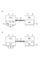
- FIG. 2 is a conceptual diagram showing an operation after the valve 14 of the chemical heat storage device 10 is opened, in which (a) is a warm-up time and (b) is an ammonia recovery time.
- NH 3 present in the heat storage material 11a of the heater 11 indicates ammonia chemically adsorbed on the heat storage material 11a
- NH 3 present in the adsorption material 12a of the storage 12 is present in the adsorbent 12a. It shows physisorbed ammonia.
- Ammonia A 11 in the heater 11 shown in FIG. 2 shows the ammonia gas phase in the heat storage material 11a is not chemically adsorbed. This is, for example, ammonia desorbed from the heat storage material 11a as the temperature of the heat storage material 11a increases, or residual ammonia remaining without being recovered in the storage 12. Depending on the amount of the ammonia A 11, it varies the pressure in the heater 11. In addition to the ammonia physically adsorbed on the adsorbent 12a, ammonia A 12 (gas) not adsorbed on the adsorbent 12a exists in the storage 12. Depending on the amount of adsorbent 12a ammonia A 12 that are not ammonia and adsorption adsorbed to vary the pressure in the storage 12.
- the heater 11 Before the heating object is warmed up, a sufficient amount of ammonia is stored in the storage 12, so the pressure in the storage 12 is higher than the pressure in the heater 11.
- the valve 14 When the valve 14 is controlled to open in this state, when the moving system is in a normal state, the valve 14 provided in the connection pipe 13 is opened, and the pressure difference between the storage 12 and the heater 11 causes a change in FIG. As shown, ammonia (gas) moves from the storage 12 to the heater 11 via the connecting pipe 13.
- the heater 11 receives heat from the object to be heated, for example, exhaust heat from high-temperature exhaust gas, and the ammonia from the heat storage material 11a inside the heater 11.
- the pressure in the heater 11 becomes higher than the pressure in the storage 12.
- the valve 14 is controlled to open, when the moving system is in a normal state, the valve 14 provided in the connection pipe 13 is opened, and the pressure difference between the heater 11 and the storage 12 causes a difference as shown in FIG. As described above, ammonia (gas) moves from the heater 11 to the storage 12 via the connection pipe 13.
- the pressure in the heater 11 and the pressure in the storage 12 are Become the same pressure (equilibrium adsorption pressure).
- the time until this equilibrium state is reached varies depending on the diffusion rate of ammonia, the length of the connecting pipe 13, the pipe diameter, and the like.
- the controller 15 includes a CPU [Central Processing Unit], a ROM [Read Only Memory], a RAM [Random Access Memory], and the like, and is a control unit that controls the chemical heat storage device 10.
- the controller 15 is connected to a temperature sensor 16 and pressure sensors 17 and 18, and acquires information necessary for control from these. Further, the controller 15 is connected to the valve 14, performs each process for controlling the chemical heat storage device 10 based on the acquired information, and performs opening / closing control of the valve 14 as necessary.
- the temperature sensor 16 and the pressure sensors 17 and 18 will be described.
- the controller 15 may be dedicated to the chemical heat storage device 10, or may be incorporated as a function of an ECU such as an engine ECU [Electronic Control Unit].
- the temperature sensor 16 is a sensor that detects the temperature of the exhaust gas flowing in the exhaust pipe 3 between the engine 2 and the heat exchanger 4.
- the temperature sensor 16 detects the temperature of the exhaust gas at regular intervals, and transmits the detected temperature information to the controller 15.
- the temperature of the exhaust gas detected by the temperature sensor 16 is substituted for the temperature of the heater 11 (and thus the heat storage material 11a), and is used in the processing of the controller 15 described below.
- the temperature of the exhaust gas detected by the temperature sensor 16 may be converted by a predetermined conversion formula to estimate the temperature of the heater 11, and the estimated temperature may be used in the processing of the controller 15 below.
- the pressure sensor 17 is a sensor that detects the pressure in the heater 11.
- the pressure sensor 17 detects the pressure in the heater 11 at regular intervals, and transmits the detected pressure information to the controller 15.
- the pressure sensor 17 corresponds to the heater internal pressure detection unit described in the claims.
- the pressure sensor 18 is a sensor that detects the pressure in the storage 12.
- the pressure sensor 18 detects the pressure in the storage 12 at regular time intervals, and transmits the detected pressure information to the controller 15.
- the pressure sensor 18 corresponds to the reservoir internal pressure detection unit described in the claims.
- the pressure sensors 17 and 18 have pressure detection response performance (response speed, etc.). Therefore, in the pressure sensors 17 and 18, it takes time until the pressure after the change is detected after the pressure in the heater 11 or the storage 12 changes according to the response speed.
- the controller 15 determines whether the temperature of the exhaust gas upstream of the heat exchanger 4 detected by the temperature sensor 16 during operation of the engine 2 is equal to or lower than the warm-up start temperature. When the controller 15 determines that the temperature of the exhaust gas is equal to or lower than the warm-up start temperature, it supplies current to the valve 14 to open the valve 14.
- the warm-up start temperature is a temperature that requires warm-up in the exhaust gas purification system 1.
- the warm-up start temperature is set based on the activation temperature of the catalyst (such as DOC5).
- the controller 15 determines whether or not the temperature of the exhaust gas detected by the temperature sensor 16 (corresponding to the temperature of the heater 11 (heat storage material 11a)) is higher than the ammonia recoverable temperature. judge.
- the controller 15 determines that the temperature of the exhaust gas is higher than the temperature at which ammonia can be recovered, current is supplied to the valve 14 to open the valve 14.
- the controller 15 determines that the temperature of the exhaust gas is equal to or lower than the temperature at which ammonia can be recovered, the controller 15 stops supplying current to the valve 14 in order to close the valve 14.
- the ammonia recoverable temperature is a temperature at which ammonia can be recovered from the heater 11 after warming up.
- the ammonia recoverable temperature is set based on the temperature at which ammonia is separated from the heat storage material 11a determined by the combination of the heat storage material 11a used in the heater 11 and ammonia. Further, the ammonia recoverable temperature may be set in consideration of the outside air temperature. For example, the higher the outside air temperature, the higher the temperature.
- the controller 15 When supplying current to the valve 14 for warm-up or supplying current to the valve 14 for ammonia recovery, the controller 15 starts supplying current to the valve 14 (that is, opening control of the valve 14). The time after the measurement is measured, and it is determined whether or not the measured time has passed for a certain time.
- the certain time is a time required for performing a stable abnormality determination using a pressure difference between the pressure in the heater 11 and the pressure in the storage 12.
- This fixed time is based on the longest time among the time from when the valve 14 is opened until the pressure reaches an equilibrium state, the delay time of pressure detection according to the response speed of the pressure sensors 17 and 18, and the like. It is good to set.
- the fixed time is, for example, several seconds.
- the controller 15 causes the pressure difference between the pressure in the heater 11 detected by the pressure sensor 17 and the pressure in the storage 12 detected by the pressure sensor 18 ( (Absolute value) is calculated. Then, the controller 15 determines whether or not the pressure difference (absolute value) is less than a threshold value.
- the threshold value is a threshold value for determining whether or not there is a difference between the pressure in the heater 11 and the pressure in the storage 12 (whether the pressure in the heater 11 and the pressure in the storage 12 are the same pressure). . This threshold value may be set based on each detection error of the pressure sensors 17 and 18.
- the controller 15 determines that the ammonia moving system including the connecting pipe 13 and the valve 14 is normal. On the other hand, when the pressure difference (absolute value) is equal to or greater than the threshold value, the controller 15 determines that there is some abnormality in the ammonia moving system, and notifies the vehicle driver of the abnormality. Examples of the abnormality notification include lighting of a warning lamp of the chemical heat storage device 10, display of information for notifying the abnormality of the chemical heat storage device 10 (particularly, the connection pipe 13 and the valve 14), and output of sound.
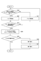
- FIG. 3 is a flowchart showing an abnormality detection operation during warm-up in the chemical heat storage device 10.
- FIG. 4 is a flowchart showing an abnormality detection operation during ammonia recovery in the chemical heat storage device 10.
- the controller 15 determines whether or not the temperature of the exhaust gas detected by the temperature sensor 16 is equal to or lower than the warm-up start temperature (S10). When it is determined in S10 that the temperature of the exhaust gas is higher than the warm-up start temperature, the controller 15 stops the supply of current to the valve 14 (S11). The valve 14 is closed because no current is supplied. In this case, ammonia cannot move through the connecting pipe 13. The determination in S10 is repeatedly performed until the temperature of the exhaust gas detected by the temperature sensor 16 becomes equal to or lower than the warm-up start temperature.
- the controller 15 supplies a current to the valve 14 (S12).
- the valve 14 opens when the supplied current flows.
- ammonia can be moved through the connecting pipe 13.
- the pressure in the storage 12 is higher than the pressure in the heater 11, and ammonia moves to the heater 11 side and flows in the connection pipe 13.
- ammonia flowing in the connection pipe 13 is supplied to the heater 11.
- the pressure in the heater 11 and the pressure in the storage 12 become the same pressure in a short time after opening the valve 14 (pressure equilibrium state).
- the supplied ammonia and the heat storage material 11a chemically react to generate heat.
- this heat is transferred to the outer cylinder of the heat exchanger 4 and is transferred to the inside of the heat exchanger 4 due to the heat transfer effect.
- the entire heat exchanger 4 is heated, and the exhaust gas flowing inside the heat exchanger 4 is quickly heated. Further, the heated exhaust gas flows downstream, and the temperature of each catalyst of DOC5, SCR7, and ASC8 rises. And when the temperature of each catalyst becomes more than the activation temperature, the exhaust gas can be purified.
- the controller 15 measures the time from the start of the opening control of the valve 14 in S12, and determines whether or not a certain time has elapsed from the start (S13). The determination in S13 is repeatedly performed until a predetermined time has elapsed. If it is determined in S13 that the predetermined time has elapsed, the controller 15 acquires the pressure in the heater 11 detected by the pressure sensor 17 and the pressure in the storage 12 detected by the pressure sensor 18 (S14). . Then, the controller 15 calculates a pressure difference (absolute value) between the pressure in the heater 11 and the pressure in the storage 12, and determines whether the pressure difference is less than a threshold value (S15).
- the controller 15 When it is determined that the pressure difference is less than the threshold value in S15 (when the pressure in the heater 11 and the pressure in the storage 12 are the same pressure after a certain time has elapsed since the start of the valve 14 opening control), the controller 15 It is determined that there is no abnormality in the ammonia moving system. On the other hand, when it is determined in S15 that the pressure difference is equal to or greater than the threshold value (when there is a difference between the pressure in the heater 11 and the pressure in the storage 12 after a certain time has elapsed since the start of the opening control of the valve 14), the controller 15 Is detected (S16), and the vehicle driver is notified of the abnormality (S17). In this case, the ammonia separated from the adsorbent 12a in the storage 12 has not moved normally to the heater 11, and either the connecting pipe 13 or the valve 14 has an abnormality.
- the controller 15 determines whether or not the temperature of the exhaust gas detected by the temperature sensor 16 (corresponding to the temperature of the heater 11 (heat storage material 11a)) is higher than the ammonia recoverable temperature (S20). .
- the controller 15 stops supplying current to the valve 14 (S21).
- the valve 14 is closed when the supply of current is stopped. In this case, ammonia cannot move through the connecting pipe 13.
- the determination in S20 is repeatedly performed until the temperature of the exhaust gas detected by the temperature sensor 16 becomes higher than the ammonia recoverable temperature.
- the controller 15 supplies a current to the valve 14 (S22).
- the valve 14 opens when the supplied current flows.
- ammonia can be moved through the connecting pipe 13.
- the pressure in the heater 11 is higher than the pressure in the storage 12, and ammonia moves to the storage 12 side and flows in the connection pipe 13.
- the ammonia flowing through the connection pipe 13 is collected by the storage 12.
- the pressure in the heater 11 and the pressure in the storage 12 become the same pressure in a short time after opening the valve 14.
- ammonia is adsorbed by the adsorbent 12a and stored.
- the controller 15 measures the time from the start of the opening control of the valve 14 in S22, and determines whether or not a certain time has elapsed from the start (S23). The determination in S23 is repeated until a certain time has elapsed. If it is determined in S23 that the predetermined time has elapsed, the controller 15 acquires the pressure in the heater 11 detected by the pressure sensor 17 and the pressure in the storage 12 detected by the pressure sensor 18 (S24). . Then, the controller 15 calculates a pressure difference between the pressure in the heater 11 and the pressure in the storage 12, and determines whether the pressure difference is less than a threshold value (S25).
- the controller 15 determines that there is no abnormality in the ammonia moving system.
- the controller 15 detects that the ammonia moving system is abnormal (S26), and notifies the vehicle driver of the abnormality (S26). S27). In this case, the ammonia separated from the heat storage material 11a in the heater 11 has not moved normally to the storage 12, and either the connecting pipe 13 or the valve 14 has an abnormality.
- this chemical heat storage device 10 when the pressure difference between the pressure in the heater 11 and the pressure in the storage 12 is greater than or equal to the threshold value after the valve 14 is controlled to open (the pressure in the heater 11 and the pressure in the storage 12. In the case where there is a difference between them, it is possible to detect an abnormality in the ammonia moving system composed of the connecting pipe 13 and the valve 14. Moreover, according to the chemical heat storage device 10, stable abnormality detection can be performed by determining abnormality after a lapse of a certain time from the start of opening control of the valve. Moreover, according to the chemical heat storage device 10, when an abnormality is detected, the driver can be prompted to promptly deal with the abnormality (repair, etc.) by notifying the driver of the abnormality.
- the present invention is applied to an exhaust gas purification system including DOC, SCR, and ASC as a catalyst and DPF as a filter.
- the present invention may be applied to an exhaust gas purification system having other configurations, for example, DOC, SCR, ASC. It is an exhaust gas purification system provided with catalysts other than DOC, SCR, and ASC.
- the vehicle is a diesel engine vehicle, it can also be applied to a gasoline engine vehicle. Further, the present invention can also be applied to other mounted objects such as ships and generators using an engine as a drive source.
- any catalyst of DOC, SCR, and ASC is heated. It is good also as a thing.
- the said embodiment although it was set as the structure which provides a heater in the perimeter of the outer peripheral part of a heat exchanger, you may provide a heater only in a part of outer peripheral part of a heating target object, and the outer peripheral part of a heating target object For example, it is set as the structure which laminated
- the reaction medium is ammonia, but other mediums such as alcohol and water may be used.
- the thermal storage material and adsorption material in case the reaction medium is ammonia was illustrated, respectively, another material is suitably used for thermal storage material and adsorption material according to the reaction medium used with a chemical thermal storage apparatus. .
- the temperature sensor for detecting the temperature of the exhaust gas is provided between the heat exchanger and the engine.
- the temperature sensor for detecting the temperature of the exhaust gas is provided in another part of the exhaust gas purification system.
- a temperature sensor may be provided between the heat exchanger and the DOC, or a temperature sensor may be provided between the heat exchanger and the engine and between the heat exchanger and the DOC. If the heater can be provided with a temperature sensor, the heater may be provided with a temperature sensor to directly detect the temperature in the heater (particularly the heat storage material).
- the abnormality is determined after a lapse of a certain time from the start of the valve opening control.
- the abnormality may be determined without waiting for a certain time after the valve opening control is started. Good.
- it is not necessary to wait for a certain time it is a case where the delay time of detection of the pressure sensor or the time from when the valve is opened until the pressure reaches an equilibrium state is very short, and it is not necessary to consider those times.
- the pressure difference between the pressure in the heater and the pressure in the storage is calculated, and the pressure difference is
- the determination as to whether or not there is this difference may be made by another method. For example, it is determined whether or not the pressure in the heater and the pressure in the storage are the same value, and if they are not the same value, it is determined that there is a difference.
- the absolute value of the pressure difference between the pressure in the heater and the pressure in the storage is calculated, and it is determined whether or not the absolute value of the pressure difference is greater than or equal to a threshold value. You may judge without. For example, in the case of warm-up, the pressure in the storage is higher before the valve opening control, so the pressure difference is obtained by subtracting the pressure in the heater from the pressure in the storage, and whether the pressure difference is greater than or equal to the threshold value. judge. In the case of ammonia recovery, since the pressure in the heater is high before the valve opening control, the pressure in the storage is subtracted from the pressure in the heater to obtain a pressure difference, and it is determined whether or not the pressure difference is equal to or greater than a threshold value. . [Second Embodiment]
- FIG. 5 is a schematic configuration diagram of an exhaust gas purification system 101 according to an embodiment.
- the exhaust gas purification system 101 includes a heat exchanger 104, a diesel oxidation catalyst (DOC) 105, and a diesel exhaust particulate removal filter (DPF) from the upstream side to the downstream side of the exhaust pipe 103 connected to the exhaust side of the engine 102. 106, a selective reduction catalyst (SCR) 107, and an ammonia slip catalyst (ASC) 108.
- Each portion where the heat exchanger 104, the DOC 105, the DPF 106, the SCR 107, and the ASC 108 are disposed is larger than the diameter of the exhaust pipe 103 where the heat exchanger 104, the DOC 105, the DPF 106, and the ASC 108 are not disposed.
- Exhaust gas discharged from the engine 102 flows through the exhaust pipe 103 and the heat exchanger 104, the DOC 105, the DPF 106, the SCR 107, and the ASC 108, and the upstream side and the downstream side are defined by the direction in which the exhaust gas flows.
- the heat exchanger 104 is a device that exchanges (transmits) heat between exhaust gas discharged from the engine 102 and a heater 111 described later.
- the heat exchanger 104 is formed of a metal material having high thermal conductivity, and the inside of the outer cylinder has a honeycomb structure.
- the heat exchanger 104 is not limited to the honeycomb structure, and a known heat exchange structure can be applied.
- the DOC 105 is a catalyst that oxidizes HC, CO, and the like contained in exhaust gas.
- the DPF 106 is a filter that collects and removes PM contained in the exhaust gas.
- SCR 107 When SCR 107 is supplied with ammonia (NH 3 ) or urea water (hydrolyzed into ammonia) by the injector 107a upstream of the exhaust pipe 103, it chemically reacts with NOx contained in the exhaust gas. This is a catalyst that reduces and purifies NOx.
- the ASC 108 is a catalyst that oxidizes ammonia flowing through the SCR 107 and flowing downstream.
- Each of the catalysts 105, 107, 108 has a temperature range (that is, an activation temperature) that can exhibit the ability to purify environmental pollutants.
- the temperature of the exhaust gas immediately after being exhausted from the engine 102 is relatively low and may be lower than its activation temperature.
- the temperature at each catalyst 105, 107, 108 needs to be quickly brought to the active temperature in order for each catalyst 105, 107, 108 to exert its purification capability.
- the exhaust gas purification system 101 includes a chemical heat storage device 110 that heats the most upstream heat exchanger 104 (exhaust gas flowing inside) and warms up the catalyst.
- the chemical heat storage device 110 is a chemical heat storage device that warms up a heating target such as a catalyst without external energy. Specifically, the chemical heat storage device 110 stores a reaction medium that stores heat from an object to be heated and desorbs from the heat storage material, and supplies the stored reaction medium to the heat storage material when necessary. In this way, the heat storage material and the reaction medium are chemically reacted, and the object to be heated is heated using reaction heat (heat radiation) during the chemical reaction. That is, it can be said that the chemical heat storage device 110 uses a reversible chemical reaction to store heat from the object to be heated and supply heat to the object to be heated.
- the chemical heat storage device 110 heats the heat exchanger 104 disposed on the upstream side of the DOC 105 that is the catalyst located on the most upstream side. Exhaust gas flows inside the heat exchanger 104, and heat exchange is performed with the exhaust gas. Therefore, by disposing the chemical heat storage device 110 on the most upstream side of the pipe through which the exhaust gas flows (the side closer to the engine 102), the exhaust gas whose temperature is not so high at the time of starting the engine 102 or the like is converted into a heat exchanger. The temperature can be quickly raised before reaching the catalyst (DOC 105, SCR 107, ASC 108) arranged downstream of the 104.
- the heat exchanger 104 corresponds to the heating object described in the claims.
- the chemical heat storage device 110 includes a heater 111, a storage 112, a connection pipe 113, a valve 114, and the like, and is controlled by a controller 115.
- the heater 111 corresponds to the heater described in the claims
- the storage 112 corresponds to the reservoir described in the claims
- the connecting pipe 113 corresponds to the claims. It corresponds to a connecting pipe
- the valve 114 corresponds to the on-off valve described in the claims
- the controller 115 corresponds to the control unit described in the claims.
- the heater 111 is provided on the entire circumference of the outer periphery of the heat exchanger 104, and the cross-sectional shape is an annular shape surrounding the heat exchanger 104.
- the heater 111 has a heat storage material 111a that generates heat by a chemical reaction with the reaction medium, and the heat storage material 111a is housed in a casing.
- ammonia is used as the reaction medium.
- the supplied ammonia and the heat storage material 111a chemically react (chemical adsorption or coordinate bond) to generate heat.
- the heat storage material 111a when the heat storage material 111a reaches a predetermined temperature or more due to exhaust heat of the exhaust gas, the heat storage material 111a and ammonia are separated (desorbed) to release ammonia, and ammonia can be recovered.
- This predetermined temperature is determined by the combination of the heat storage material 111a used in the heater 111 and the reaction medium.
- the heat storage material 111 a is disposed so as to be in contact with the entire circumference of the outer peripheral surface of the outer cylinder of the heat exchanger 104.
- a material that generates heat by chemically reacting with ammonia as a reaction medium and can raise the exhaust gas passing through the heat exchanger 104 to an activation temperature of a catalyst (such as DOC 105) or higher is used.
- the additive which improves thermal conductivity with the thermal storage material 111a.
- the additive include carbon fibers, carbon beads, SiC beads, metal beads such as Cu, Ag, Ni, Ci—Cr, Al, Fe, and stainless steel, polymer beads, and polymer fibers.
- the casing is disposed so as to cover the entire outer peripheral side of the heater 111 and the entire upstream end and downstream end of the heater 111, and a sealed space is formed between the outer peripheral surface of the outer cylinder of the heat exchanger 104.
- the heat storage material 111a is enclosed therein. Thus, since the heat storage material 111a is sealed in the sealed space, it can repeatedly react with ammonia.
- the heat storage material 111a after reacting with ammonia stores heat from the high-temperature exhaust gas flowing through the heat exchanger 104, it desorbs ammonia.
- the storage 112 contains an adsorbent 112a that can hold (adsorb) and separate (release) ammonia as a reaction medium.
- adsorbent 112a for example, activated carbon capable of storing ammonia by physical adsorption is used.
- ammonia is separated from the adsorbent 112 a and supplied to the heater 111, and after the warm-up is completed, exhaust heat of the exhaust gas is received and the ammonia desorbed from the heat storage material 111 a is physically adsorbed to the adsorbent 112 a. Collect again.
- the adsorbent 112a is not limited to activated carbon, and for example, mesoporous material having mesopores such as mesoporous silica, mesoporous carbon and mesoporous alumina, or zeolite and silica gel may be used.
- the total amount of ammonia that can be stored is determined according to the size of the storage 112 (particularly, the capacity of the built-in adsorbent 112a).
- FIG. 6A is a graph showing the relationship between the temperature in the storage 112 and the ammonia saturated vapor pressure, where the horizontal axis is temperature (° C.) and the vertical axis is ammonia saturated vapor pressure (kPa).
- Adsorption amount (g) is a graph showing the relationship between the temperature in the storage 112 and the ammonia saturated vapor pressure, where the horizontal axis is temperature (° C.) and the vertical axis is ammonia saturated vapor pressure (kPa).
- the temperature in the storage 112 and the ammonia saturated vapor pressure have a relationship indicated by an ammonia saturated vapor pressure curve C1 in which the ammonia saturated vapor pressure increases as the temperature increases. Therefore, the ammonia saturated vapor pressure in the storage 112 can be obtained from the temperature in the storage 112 with reference to the ammonia saturated vapor pressure curve C1.
- the relative pressure in the storage 112 and the ammonia adsorption amount are represented by an ammonia adsorption amount curve C2 in which the ammonia adsorption amount (ammonia storage amount) increases as the relative pressure increases. There is.
- the ammonia adsorption amount in the storage 112 can be obtained from the relative pressure with reference to the ammonia adsorption amount curve C2. If the temperature and pressure in the storage 112 can be obtained from these two relationships, the ammonia saturated vapor pressure is obtained from the temperature in the storage 112, the relative pressure is calculated from the ammonia saturated vapor pressure and the pressure in the storage 112, and this The ammonia adsorption amount can be determined from the relative pressure.
- the ammonia adsorption amount stored in the storage 112 can be estimated from the temperature and pressure in the storage 112. In order to keep the pressure of the storage 112 at a predetermined pressure from the ammonia adsorption amount of the storage 112, the remaining amount is subtracted to estimate the recovery amount. Further, the amount of ammonia recovered in the storage 112 is divided by the amount of ammonia required for the exothermic reaction in order to obtain a desired amount of heat (this amount is hereinafter referred to as “ammonia total recovery amount”). The recovery rate of ammonia recovered in the storage 112 can be obtained.
- the connection pipe 113 is a pipe that connects the heater 111 and the storage 112, and serves as a flow path through which a reaction medium (ammonia) flows between the heater 111 and the storage 112.
- the valve 114 is disposed in the middle of the connecting pipe 113 and is a valve that opens and closes the ammonia flow path between the heater 111 and the storage 112. When the valve 114 is opened, ammonia can be transferred between the heater 111 and the storage 112 via the connection pipe 113. Control of opening / closing of the valve 114 is performed by the controller 115.
- the valve 114 is an electromagnetic normally closed valve and opens when a current is passed.
- the valve 114 may be a valve other than an electromagnetic type.
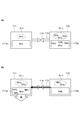
- FIGS. 7A and 7B are conceptual diagrams showing the warm-up operation of the chemical heat storage device 110, where FIG. 7A shows a state before the valve 114 is opened, and FIG. 7B shows a state after the valve 114 is opened.
- FIGS. 8A and 8B are conceptual diagrams showing the operation of the chemical heat storage device 110 during recovery of ammonia.
- FIG. 8A shows a state before the valve 114 is opened
- FIG. 8B shows a state after the valve 114 is opened.
- NH 3 present in the heat storage material 111 a of the heater 111 indicates ammonia chemically adsorbed on the heat storage material 111 a
- NH 3 present in the adsorption material 112 a of the storage 112 is the adsorbent.
- 112a shows ammonia physically adsorbed.
- This is, for example, ammonia desorbed from the heat storage material 111a as the temperature of the heat storage material 111a increases, or residual ammonia remaining without being recovered in the storage 112.
- the pressure in the heater 111 changes.
- ammonia A 112 (gas) that is not adsorbed by the adsorbent 112a is present in addition to the ammonia that is physically adsorbed by the adsorbent 112a.
- the pressure in the storage 112 changes according to the amount of ammonia adsorbed on the adsorbent 112a and the amount of ammonia A12 not adsorbed.
- a sufficient amount of ammonia is stored in the storage 112, so the pressure in the storage 112 is higher than the pressure in the heater 111.
- the valve 114 is controlled to open in this state, when the moving system is in a normal state, the valve 114 provided in the connection pipe 113 is opened, and the pressure difference between the storage 112 and the heater 111 causes the difference in FIG. As shown, ammonia (gas) moves from the storage 112 to the heater 111 via the connecting pipe 113. Therefore, the amount of ammonia in the storage 112 is reduced, and the pressure in the storage 112 is lowered.
- the heater 111 receives heat from the object to be heated (for example, exhaust heat of high-temperature exhaust gas), and ammonia is received from the heat storage material 111a inside the heater 111. Since desorption occurs, the pressure in the heater 111 becomes higher than the pressure in the storage 112.
- the valve 114 is controlled to open, when the moving system is in a normal state, the valve 114 provided in the connection pipe 113 is opened, and the pressure difference between the heater 111 and the storage 112 causes a difference in FIG. As shown, ammonia (gas) moves from the heater 111 to the storage 112 via the connection pipe 113.
- the amount of ammonia in the storage 112 increases and the pressure in the storage 112 increases.
- the storage 112 has already recovered a quantity of ammonia that is in a fully recovered state or close to the fully recovered state before the ammonia recovery, the ammonia (gas) will remain in the heater 111 even if the valve 114 is opened for ammonia recovery. To the storage 112 via the connection pipe 113 or hardly.
- the pressure in the heater 111 and the pressure in the storage 112 are Become the same pressure (equilibrium adsorption pressure). From the opening of the valve 114 to the equilibrium state, the pressure in the heater 111 and the pressure in the storage 112 fluctuate rapidly. The time until this equilibrium state is reached varies depending on the diffusion rate of ammonia, the length of the connecting pipe 113, the pipe diameter, and the like.
- an abnormality occurs in the ammonia moving system composed of the connection pipe 113 and the valve 114, the movement of ammonia between the heater 111 and the storage 112 via the connection pipe 113 is not performed as in the normal state. There is a case. In this case, even if a predetermined time has elapsed since the opening control of the valve 114 was started, the pressure in the storage 112 does not change or hardly changes.
- an abnormality of the ammonia moving system for example, when the valve 114 does not open due to mechanical failure or electrical failure due to aging or the like, or when a part of the heat storage material 111a is missing is clogged in the connection pipe 113, For example, a part of the connection pipe 113 is damaged.
- the controller 115 includes a CPU [Central Processing Unit], a ROM [Read Only Memory], a RAM [Random Access Memory], and the like, and is a control unit that controls the chemical heat storage device 110.
- Various sensors such as temperature sensors 116 and 117 and a pressure sensor 118 are connected to the controller 115, and information necessary for control is appropriately acquired from these by a plurality of sensors.
- the controller 115 is connected to the valve 114, performs each process for controlling the chemical heat storage device 110 based on the acquired information, and performs opening / closing control of the valve 114 as necessary.
- the controller 115 may be dedicated to the chemical heat storage device 110, or may be incorporated as a function of an ECU such as an engine ECU [Electronic Control Unit].
- the temperature sensor 116 is a sensor that detects the temperature of the exhaust gas flowing in the exhaust pipe 103 between the engine 102 and the heat exchanger 104.
- the temperature sensor 116 detects the temperature of the exhaust gas at regular intervals, and transmits the detected temperature information to the controller 115.
- the temperature of the exhaust gas detected by the temperature sensor 116 is substituted for the temperature of the heater 111 (and thus the heat storage material 111a), and is used in the processing of the controller 115 below.
- the temperature of the heater 111 may be estimated by converting the temperature of the exhaust gas detected by the temperature sensor 116 using a predetermined conversion formula, and the estimated temperature may be used in the processing of the controller 115 below.
- the temperature sensor 117 is a sensor that detects the temperature in the storage 112.
- the temperature sensor 117 detects the temperature in the storage 112 at regular intervals, and transmits the detected temperature information to the controller 115.
- the pressure sensor 118 is a sensor that detects the pressure in the storage 112.
- the pressure sensor 118 detects the pressure in the storage 112 at regular intervals, and transmits the detected pressure information to the controller 115.
- the pressure sensor 118 has pressure detection response performance (response speed, etc.). Therefore, in the pressure sensor 118, it takes time until the pressure after the change is detected after the pressure in the storage 112 changes according to the response speed.
- the pressure sensor 118 corresponds to the pressure detector described in the claims.
- the controller 115 determines whether or not the temperature of the exhaust gas upstream of the heat exchanger 104 detected by the temperature sensor 116 during operation of the engine 102 is equal to or lower than the warm-up start temperature. When the controller 115 determines that the exhaust gas temperature is equal to or lower than the warm-up start temperature, the controller 115 supplies current to the valve 114 to open the valve 114.
- the warm-up start temperature is a temperature that requires warm-up in the exhaust gas purification system 101.
- the warm-up start temperature is set based on the activation temperature of the catalyst (such as DOC 105).
- the controller 115 determines whether or not the temperature of the exhaust gas detected by the temperature sensor 116 (corresponding to the temperature of the heater 111 (heat storage material 111a)) is higher than the ammonia recoverable temperature. judge. When the controller 115 determines that the temperature of the exhaust gas is higher than the temperature at which ammonia can be recovered, current is supplied to the valve 114 to open the valve 114. Further, when the controller 115 determines that the temperature of the exhaust gas is equal to or lower than the temperature at which ammonia can be recovered, the controller 115 stops the supply of current to the valve 114 in order to close the valve 114.
- the ammonia recoverable temperature is a temperature at which ammonia can be recovered from the heater 111 after warm-up.
- the ammonia recoverable temperature is set based on the temperature at which ammonia is separated from the heat storage material 111a determined by the combination of the heat storage material 111a and ammonia used in the heater 111. Further, the ammonia recoverable temperature may be set in consideration of the outside air temperature. For example, the higher the outside air temperature, the higher the temperature.
- the controller 115 When supplying current to the valve 114 for warm-up or supplying current to the valve 114 for ammonia recovery, the controller 115 detects the pressure in the storage 112 detected by the pressure sensor 118 immediately before supplying the current. Keep it. Then, the controller 115 measures the time since the supply of current to the valve 114 (that is, the opening control of the valve 114) is started, and determines whether or not the measured time has passed for a certain time.
- the certain time is a time necessary for performing a stable abnormality determination using a difference in pressure in the storage 112 before and after the opening control of the valve 114.
- This fixed time is set based on the longest time among the time from when the valve 114 is opened until the pressure reaches an equilibrium state, the delay time of pressure detection according to the response speed of the pressure sensor 118, and the like. Good.
- the fixed time is, for example, several seconds.
- the controller 115 detects the pressure in the storage 112 before the opening control of the valve 114 being held and the pressure sensor 118 after a certain period of time has elapsed after the opening control.
- the pressure difference (absolute value) from the stored pressure in the storage 112 is calculated.
- the controller 115 determines whether or not the pressure difference (absolute value) is equal to or greater than a threshold value.
- the threshold value is a threshold value for determining whether or not there is a change in pressure in the storage 112 before and after the opening control of the valve 114. This threshold value may be set based on a detection error of the pressure sensor 118 or the like.
- the controller 115 determines that the ammonia moving system including the connection pipe 113 and the valve 114 is normal. On the other hand, when the pressure difference (absolute value) is less than the threshold value, the controller 115 determines that there is some abnormality in the ammonia moving system, and notifies the vehicle driver of the abnormality.
- This abnormality notification includes, for example, lighting of a warning lamp of the chemical heat storage device 110, display of information for notifying the abnormality of the chemical heat storage device 110 (particularly, the connection pipe 113 and the valve 114), and output of sound.
- the controller 115 uses the temperature in the storage 112 detected by the temperature sensor 117 before supplying current, as shown in FIG.
- the ammonia saturation vapor pressure is obtained with reference to the ammonia saturation vapor pressure curve C1.
- the controller 115 calculates the relative pressure by dividing the pressure in the storage 112 detected by the pressure sensor 118 by the ammonia saturated vapor pressure.
- the controller 115 uses this relative pressure to acquire the ammonia adsorption amount in the storage 112 with reference to the ammonia adsorption amount curve C2 shown in FIG.
- the controller 115 subtracts the remaining amount in order to keep the pressure of the storage 112 at a predetermined pressure from the ammonia adsorption amount, and acquires the ammonia recovery amount.
- the controller 115 calculates the ammonia recovery rate by dividing this ammonia recovery amount by the total ammonia recovery amount. Then, the controller 115 determines whether or not the ammonia recovery rate is equal to or higher than a predetermined rate. When the controller 115 determines that the ammonia recovery rate is equal to or higher than the predetermined rate, the controller 115 does not perform abnormality determination based on the pressure difference in the storage 112 before and after the opening control of the valve 114.
- abnormality determination is performed only when the ammonia recovery rate is less than a predetermined rate. Whether the ammonia recovery rate is equal to or higher than a predetermined rate may be determined before the opening control of the valve 114 or after the opening control of the valve 114.
- the ammonia recovery rate is a value from 0 to 100%, and is 100% when the ammonia recovery amount recovered in the storage 112 becomes equal to the total ammonia recovery amount.
- the temperature sensor 117, the pressure sensor 118, and the controller 115 correspond to the recovery rate acquisition unit described in the claims.
- the predetermined rate is a threshold value for determining whether the ammonia recovery state in the storage 112 is a fully recovered state or a state close to the fully recovered state.
- the predetermined rate is, for example, 90% to 99%.
- the pressure in the storage 112 does not or hardly fluctuate before and after the opening control of the valve 114, and an abnormality cannot be detected from the pressure difference in the storage 112 before and after the opening control.
- a predetermined rate may be set in relation to this threshold value. For example, the predetermined rate is decreased as the threshold value increases.
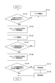
- FIG. 9 is a flowchart showing an abnormality detection operation during warm-up in the chemical heat storage device 110.
- FIG. 10 is a flowchart showing an abnormality detection operation during ammonia recovery in the chemical heat storage device 110.
- the controller 115 determines whether or not the temperature of the exhaust gas detected by the temperature sensor 116 is equal to or lower than the warm-up start temperature (S110). If it is determined in S110 that the temperature of the exhaust gas is higher than the warm-up start temperature, the controller 115 stops supplying current to the valve 114 (S111). The valve 114 is closed because no current is supplied. In this case, the movement of ammonia through the connecting pipe 113 is impossible. The determination in S110 is repeatedly performed until the temperature of the exhaust gas detected by the temperature sensor 116 becomes equal to or lower than the warm-up start temperature.
- the controller 115 acquires the pressure in the storage 112 detected by the pressure sensor 118 and maintains the pressure before the valve 114 is opened. (S112). Then, the controller 115 supplies current to the valve 114 (S113). When there is no abnormality in the connection pipe 113 and the valve 114, the valve 114 opens when the supplied current flows. As a result, ammonia can be moved through the connecting pipe 113. At this time, the pressure in the storage 112 is higher than the pressure in the heater 111, and ammonia moves to the heater 111 side and flows through the connection pipe 113. Then, ammonia flowing in the connection pipe 113 is supplied to the heater 111.
- the pressure in the heater 111 and the pressure in the storage 112 become the same pressure (pressure equilibrium state).
- the pressure in the storage 112 decreases.
- the supplied ammonia and the heat storage material 111a chemically react to generate heat.
- this heat is transferred to the outer cylinder of the heat exchanger 104 and is transferred to the inside of the heat exchanger 104 by the heat transfer effect.
- the entire heat exchanger 104 is heated, and the exhaust gas flowing inside the heat exchanger 104 is quickly heated.
- the exhaust gas whose temperature has been increased flows downstream, and each catalyst of the DOC 105, the SCR 107, and the ASC 108 is increased in temperature. And when the temperature of each catalyst becomes more than the activation temperature, the exhaust gas can be purified.
- the controller 115 measures the time from the start of the opening control of the valve 114 in S113, and determines whether or not a certain time has elapsed from the start (S114). The determination in S114 is repeated until a certain time has elapsed. If it is determined in S114 that the predetermined time has elapsed, the controller 115 acquires the pressure in the storage 112 detected by the pressure sensor 118 after the opening control of the valve 114 (S115). Then, the controller 115 calculates the pressure difference (absolute value) between the pressure in the storage 112 before the valve 114 is opened and the pressure in the storage 112 after the valve 114 is opened. It is determined whether or not (S116).
- the controller 115 If it is determined in S116 that the pressure difference is equal to or greater than the threshold value (when the pressure in the storage 112 fluctuates (especially decreases) before and after the opening control of the valve 114), the controller 115 has an abnormality in the ammonia moving system. Judge that there is no. On the other hand, when it is determined in S116 that the pressure difference is less than the threshold value (when the pressure in the storage 112 has not changed before and after the opening control of the valve 114), the controller 115 indicates that the ammonia moving system is abnormal. It detects (S117) and notifies the driver of the vehicle that there is an abnormality (S118). In this case, the ammonia separated from the adsorbent 112a in the storage 112 has not moved normally to the heater 111, and either the connection pipe 113 or the valve 114 has an abnormality.
- the controller 115 determines whether or not the temperature of the exhaust gas detected by the temperature sensor 116 (corresponding to the temperature of the heater 111 (heat storage material 111a)) is higher than the ammonia recoverable temperature (S120). .
- the controller 115 stops supplying current to the valve 114 (S121).
- the valve 114 is closed when the supply of current is stopped. In this case, ammonia cannot move through the connecting pipe 113.
- the determination in S120 is repeatedly performed until the temperature of the exhaust gas detected by the temperature sensor 116 becomes higher than the ammonia recoverable temperature.
- the controller 115 stores the temperature from the temperature in the storage 112 detected by the temperature sensor 117 and the pressure in the storage 112 detected by the pressure sensor 118.
- the ammonia adsorption amount at 112 is acquired, and the ammonia recovery amount is obtained by subtracting the remaining residual amount from the ammonia adsorption amount to maintain the pressure of the storage 112 at a predetermined pressure.
- the ammonia recovery rate is obtained by dividing by the recovered amount (S122). Then, the controller 115 determines whether or not the ammonia recovery rate is equal to or higher than a predetermined rate (S123). When it is determined in S123 that the ammonia recovery rate is equal to or higher than the predetermined rate, the controller 115 supplies a current to the valve 114 (S124). When there is no abnormality in the connection pipe 113 and the valve 114, the valve 114 opens when the supplied current flows. As a result, ammonia can be moved through the connecting pipe 113. At this time, the pressure in the heater 111 is higher than the pressure in the storage 112, and ammonia moves to the storage 112 side and flows in the connection pipe 113.
- the ammonia flowing through the connection pipe 113 is collected by the storage 112.
- the pressure in the heater 111 and the pressure in the storage 112 become the same pressure in a short time after opening the valve 114.
- the pressure in the storage 112 has increased.
- ammonia is adsorbed by the adsorbent 112a and stored.
- the controller 115 acquires the pressure in the storage 112 detected by the pressure sensor 118 and holds the pressure before the valve 114 is opened. (S125). Then, the controller 115 supplies a current to the valve 114 in the same manner as the process of S124 (S126). The controller 115 measures the time from the start of the opening control of the valve 114 in S126, and determines whether or not a certain time has elapsed from the start (S127). The determination in S127 is repeated until a certain time has elapsed.
- the controller 115 acquires the pressure in the storage 112 detected by the pressure sensor 118 after the opening control of the valve 114 (S128). Then, the controller 115 calculates the pressure difference (absolute value) between the pressure in the storage 112 before the valve 114 is opened and the pressure in the storage 112 after the valve 114 is opened. It is determined whether or not (S129). If it is determined in S129 that the pressure difference is equal to or greater than the threshold (when the pressure in the storage 112 fluctuates (especially increases) before and after the valve 114 is opened), the controller 115 has an abnormality in the ammonia moving system. Judge that there is no.
- the controller 115 when it is determined in S129 that the pressure difference is less than the threshold value (when the pressure in the storage 112 has not changed before and after the opening control of the valve 114), the controller 115 indicates that there is an abnormality in the ammonia moving system. It detects (S130) and notifies the driver of the vehicle that there is an abnormality (S131). In this case, the ammonia separated from the heat storage material 111a in the heater 111 has not moved normally to the storage 112, and either the connection pipe 113 or the valve 114 has an abnormality.
- this chemical heat storage device 110 when the pressure difference in the storage 112 before and after the opening control of the valve 114 is less than the threshold value (when there is no fluctuation in the pressure in the storage 112), it is determined that there is an abnormality. Abnormality of the ammonia moving system composed of the pipe 113 and the valve 114 can be detected. Further, according to the chemical heat storage device 110, it is possible to detect abnormality using only the pressure on the storage 112 side. Since the temperature in the storage 112 is smaller than that in the heater 111, the pressure in the storage 112 is less affected by the temperature than the pressure in the heater 111. Therefore, stable abnormality detection can be performed by using the pressure on the storage 112 side.
- stable abnormality detection can be performed by performing the determination after a lapse of a certain period of time after starting the opening control of the valve 114. Further, according to the chemical heat storage device 110, when the ammonia recovery rate is equal to or higher than a predetermined rate during ammonia recovery, the abnormality determination is not performed. Therefore, the abnormality determination can be performed only when the abnormality can be detected. Further, according to the chemical heat storage device 110, when an abnormality is detected, the driver can be promptly dealt with (such as repair) by notifying the driver of the abnormality.
- the present invention is applied to an exhaust gas purification system including DOC, SCR, and ASC as a catalyst and DPF as a filter.
- the present invention may be applied to an exhaust gas purification system having other configurations, for example, DOC, SCR, ASC.
- the present invention may be applied to an exhaust gas purification system that does not include any one or two of these catalysts, or an exhaust gas purification system that includes a catalyst other than DOC, SCR, and ASC.
- the vehicle is a diesel engine vehicle, it can also be applied to a gasoline engine vehicle. Further, the present invention can also be applied to other mounted objects such as ships and generators using an engine as a drive source.
- any catalyst of DOC, SCR, and ASC is heated. It is good also as a thing.
- a heater may be provided inside the exhaust gas pipe.
- a configuration in which a plurality of heaters and heat exchange units are alternately stacked may be employed.
- reaction medium is ammonia in the above embodiment
- other reaction medium such as alcohol or water
- each material of the heat storage material and the adsorbent when the reaction medium is ammonia is exemplified, but depending on the reaction medium used in the chemical heat storage device, other materials may be used as appropriate for the heat storage material and the adsorbent. Used.
- the temperature sensor for detecting the temperature of the exhaust gas is provided between the heat exchanger and the engine.
- the temperature sensor for detecting the temperature of the exhaust gas is provided in another part of the exhaust gas purification system.
- a temperature sensor may be provided between the heat exchanger and the DOC, or a temperature sensor may be provided between the heat exchanger and the engine and between the heat exchanger and the DOC. If the heater can be provided with a temperature sensor, the heater may be provided with a temperature sensor to directly detect the temperature in the heater (particularly the heat storage material).
- the abnormality is determined after a lapse of a certain time from the start of the valve opening control.
- the abnormality may be determined without waiting for a certain time after the valve opening control is started. Good.
- it is a case where the delay time of detection of the pressure sensor or the time from when the valve is opened until the pressure reaches an equilibrium state is very short, and it is not necessary to consider those times.
- the pressure at the time when the pressure in the storage before the pressure reaches the equilibrium state after the opening control of the valve is rapidly detected is detected. You may determine abnormality using a pressure.
- the pressure between the pressure in the storage before the opening control and the pressure in the storage after the opening control is calculated, and it is determined whether or not the pressure difference is equal to or greater than a threshold value.
- the determination as to whether or not there is a change in the pressure may be performed by another method. For example, it is determined whether or not the pressure in the storage before the opening control and the pressure in the storage after the opening control are the same value.
- the absolute value of the pressure difference between the pressure in the storage before the valve opening control and the pressure in the storage after the opening control is calculated, and it is determined whether or not the absolute value of the pressure difference is greater than or equal to a threshold value.
- the determination may be made without using the absolute value. For example, in warm-up, the pressure in the storage decreases after the open control, so the pressure difference is obtained by subtracting the pressure in the storage after the open control from the pressure in the storage before the open control. It is determined whether or not the threshold value is exceeded. In the case of ammonia recovery, the pressure in the storage increases after the open control, so the pressure difference is obtained by subtracting the pressure in the storage before the open control from the pressure in the storage after the open control. It is determined whether or not.
- the ammonia recovery rate is equal to or higher than a predetermined rate at the time of ammonia recovery.
- a certain amount of ammonia exists in the heater before ammonia recovery (for example, In the case where warm-up is performed before ammonia recovery), it is not necessary to determine whether the ammonia recovery rate is equal to or higher than a predetermined rate.
- ASC Ammonia slip contact
- 110 chemical heat storage device, 111 ... heater, 111a ... heat storage material, 112 ... storage, 112a ... adsorbent, 113 ... connecting pipe, 114 ... valve, 115 ... controller, 116,117 ... temperature sensor, 118 ... Pressure sensor.
- DOC diesel oxidation catalyst
- DPF diesel exhaust particulate removal Filter
- SCR Selective reduction catalyst
- ASC Ammonia slip contact
- 110 ... chemical heat storage device, 111 ... heater, 111a ... heat storage material, 112 ... storage, 112a ... adsorbent, 113 ... connecting pipe, 114 ... valve, 115 ... controller, 116,117 ... temperature sensor, 118 ... Pressure sensor.
Landscapes
- Engineering & Computer Science (AREA)
- Physics & Mathematics (AREA)
- Thermal Sciences (AREA)
- Mechanical Engineering (AREA)
- General Engineering & Computer Science (AREA)
- Exhaust Gas After Treatment (AREA)
Abstract
加熱対象物を加熱する化学蓄熱装置であって、反応媒体と化学反応して熱を発生させる蓄熱材を有し、加熱対象物を加熱する加熱器と、反応媒体を貯蔵する貯蔵器と、加熱器と貯蔵器とを接続し、反応媒体が流れる接続管と、接続管に設けられる開閉弁と、開閉弁の開閉を制御する制御部と、加熱器、加熱器、及び接続管によって構成される系の圧力を検出する圧力検出部と、を備え、制御部は、圧力検出部によって検出された系の圧力の検出結果に基づいて異常の有無を判定する。
Description
本発明は、化学蓄熱装置に関する。
車両等の排気系には、エンジンから排出される排気ガスに含まれる環境汚染物質(HC、CO、NOx等)を浄化するために、触媒等が設けられている。触媒には、浄化能力を活性化するための最適温度(活性温度)が存在する。エンジン始動時は、排気ガスの温度が低く、触媒の活性温度に達するまでに時間を要する。そこで、エンジン始動時等の排気ガスの温度が低いときに触媒の活性温度まで短時間で温度上昇させるために、触媒を暖機するための加熱装置を設ける場合がある。この加熱装置としては、エネルギロス(燃費ロス)を低減して暖機を行うために、反応媒体と蓄熱材との化学反応の反応熱を利用した化学蓄熱装置がある。化学蓄熱装置としては、例えば、特許文献1に、加熱対象物としての車両排気系の触媒を暖機する蓄熱装置において、触媒の外周部に設けられた蓄熱材を有する反応器(加熱器)と反応媒体としてのアンモニアを貯蔵する貯蔵器とが管路を介して接続され、この管路に開閉弁が設けられることが開示されている。
加熱器でアンモニアを蓄熱材と反応させて加熱対象物を加熱する暖機を行う場合又は貯蔵器で蓄熱材から脱離したアンモニアの回収を行う場合、所望の量のアンモニアを加熱器と貯蔵器との間で移動させる。このとき、管路に設けられた開閉弁は開制御され、管路を介したアンモニアの移動が可能となっている。しかしながら、開閉弁の故障や管路の詰まり等、アンモニアの移動経路(移動系)に異常が発生すると、加熱器と貯蔵器との間におけるアンモニアの移動が阻害され、意図したとおりの暖機やアンモニアの回収ができなくなる。
そこで、本技術分野においては、反応媒体の移動系の異常を検知できる化学蓄熱装置が要請されている。
本発明の一側面に係る化学蓄熱装置は、加熱対象物を加熱する化学蓄熱装置であって、反応媒体と化学反応して熱を発生させる蓄熱材を有し、加熱対象物を加熱する加熱器と、反応媒体を貯蔵する貯蔵器と、加熱器と貯蔵器とを接続し、反応媒体が流れる接続管と、接続管に設けられる開閉弁と、開閉弁の開閉を制御する制御部と、加熱器、貯蔵器、及び接続管によって構成される系の圧力を検出する圧力検出部と、を備え、制御部は、圧力検出部によって検出された系の圧力の検出結果に基づいて異常の有無を判定する。
この化学蓄熱装置は、加熱対象物を加熱可能な箇所に配置される加熱器とそれ以外の箇所に配置される貯蔵器を備え、加熱器と貯蔵器とが接続管によって接続されている。接続管には開閉弁が配設されており、貯蔵器から加熱器に反応媒体を供給する場合や加熱器から貯蔵器に反応媒体を回収する場合に開閉弁が開かれる。化学蓄熱装置では、この開閉弁の開閉制御を制御部で行う。貯蔵器から加熱器に反応媒体を供給する場合、開閉弁が開かれる前は貯蔵器内のほうが加熱器内よりも圧力が高い。そのため、開閉弁が開かれると、反応媒体が貯蔵器から加熱器へ接続管を介して移動し、圧力が平衡状態になると加熱器内の圧力と貯蔵器内の圧力とが同じ圧力になる。加熱器から貯蔵器に反応媒体を回収する場合、開閉弁が開かれる前は加熱器内のほうが貯蔵器内よりも圧力が高い。そのため、開閉弁が開かれると、反応媒体が加熱器から貯蔵器へ接続管を介して移動し、圧力が平衡状態になると加熱器内の圧力と貯蔵器内の圧力とが同じ圧力になる。しかし、故障で開閉弁が開かないなどの要因で接続管を介して反応媒体が移動できないような状態になっていると、開閉弁の開制御が行われても、加熱器内の圧力と貯蔵器内の圧力とが同じ圧力にならない。このような異常を検知するために、化学蓄熱装置は、加熱器、貯蔵器、及び接続管によって構成される系の圧力を検出する圧力検出部を備えており、圧力検出部によって検出された系の圧力の検出結果に基づいて異常の有無を判定する。この系の圧力に異常がある場合、反応媒体の移動系(接続管、開閉弁)に異常があるので、制御部では異常があると判定できる。このように、化学蓄熱装置では、圧力検出部によって検出された系の圧力の検出結果に基づいて異常の有無を判定することにより、反応媒体の移動系の異常を検知できる。
一実施形態の化学蓄熱装置は、加熱対象物を加熱する化学蓄熱装置であって、反応媒体と化学反応して熱を発生させる蓄熱材を有し、加熱対象物を加熱する加熱器と、反応媒体を貯蔵する貯蔵器と、加熱器と貯蔵器とを接続し、反応媒体が流れる接続管と、接続管に設けられる開閉弁と、開閉弁の開閉を制御する制御部と、加熱器内の圧力を検出する加熱器内圧検出部と、貯蔵器内の圧力を検出する貯蔵器内圧検出部とを備え、制御部は、反応媒体を加熱器と貯蔵器との間で移動させるために開閉弁の開制御を行った後に加熱器内圧検出部で検出した加熱器内の圧力と、貯蔵器内圧検出部で検出した貯蔵器内の圧力とに差異があるか否かを判定し、当該判定の結果に基づいて異常の有無を判定する。
この化学蓄熱装置は、加熱対象物を加熱可能な箇所に配置される加熱器とそれ以外の箇所に配置される貯蔵器を備え、加熱器と貯蔵器とが接続管によって接続されている。接続管には開閉弁が配設されており、貯蔵器から加熱器に反応媒体を供給する場合や加熱器から貯蔵器に反応媒体を回収する場合に開閉弁が開かれる。化学蓄熱装置では、この開閉弁の開閉制御を制御部で行う。貯蔵器から加熱器に反応媒体を供給する場合、開閉弁が開かれる前は貯蔵器内のほうが加熱器内よりも圧力が高い。そのため、開閉弁が開かれると、反応媒体が貯蔵器から加熱器へ接続管を介して移動し、圧力が平衡状態になると加熱器内の圧力と貯蔵器内の圧力とが同じ圧力になる。加熱器から貯蔵器に反応媒体を回収する場合、開閉弁が開かれる前は加熱器内のほうが貯蔵器内よりも圧力が高い。そのため、開閉弁が開かれると、反応媒体が加熱器から貯蔵器へ接続管を介して移動し、圧力が平衡状態になると加熱器内の圧力と貯蔵器内の圧力とが同じ圧力になる。しかし、故障で開閉弁が開かないなどの要因で接続管を介して反応媒体が移動できないような状態になっていると、開閉弁の開制御が行われても、加熱器内の圧力と貯蔵器内の圧力とが同じ圧力にならない。このような異常を検知するために、化学蓄熱装置は、加熱器内圧検出部と貯蔵器内圧検出部を備えており、制御部で開閉弁の開制御を行った後に加熱器内圧検出部で検出された加熱器内の圧力と貯蔵器内圧検出部で検出された貯蔵器内の圧力とに差異があるか否かを判定する。この差異には、加熱器内圧検出部や貯蔵器内圧検出部での検出誤差等による差異は含まれない。加熱器内の圧力と貯蔵器内の圧力とに差異がない場合、接続管を介して反応媒体が移動できている。一方、加熱器内の圧力と貯蔵器内の圧力とに差異がある場合、接続管を介して反応媒体が移動できていない。この場合、反応媒体の移動系(接続管、開閉弁)に異常があるので、制御部では異常があると判定できる。このように、化学蓄熱装置では、開閉弁の開制御を行った後に加熱器内の圧力と貯蔵器内の圧力とに差異があるか否かに基づいて異常の有無を判定することにより、反応媒体の移動系の異常を検知できる。
一実施形態の化学蓄熱装置では、制御部は、加熱器内圧検出部で検出した加熱器内の圧力と貯蔵器内圧検出部で検出した貯蔵器内の圧力との圧力差を算出し、当該算出した圧力差が閾値以上の場合に異常と判定する。
制御部では、加熱器内の圧力と貯蔵器内の圧力とに差異があるかを判定するために、加熱器内の圧力と貯蔵器内の圧力との圧力差を算出し、その圧力差が閾値以上か否かを判定する。圧力差が閾値未満の場合、加熱器内の圧力と貯蔵器内の圧力とに差異がない。一方、圧力差が閾値以上の場合、加熱器内の圧力と貯蔵器内の圧力とに差異があり、反応媒体の移動系に異常がある。このように、化学蓄熱装置では、加熱器内の圧力と貯蔵器内の圧力との圧力差が閾値以上かを判定することにより、加熱器内の圧力と貯蔵器内の圧力とに差異があるか否かを判定できる。
一実施形態の化学蓄熱装置では、制御部は、開閉弁の開制御を開始してから一定時間経過後に判定を行う。
開閉弁が開かれると、圧力が平衡状態となって、加熱器内の圧力と貯蔵器内の圧力とが同じ圧力になる。この平衡状態になるまでの時間は、反応媒体の拡散速度及び接続管の長さや管径等による。また、加熱器内圧検出部や貯蔵器内圧検出部は、検出の応答性能に応じて、加熱器内や貯蔵器内の圧力が変化してからその変化後の圧力を検出するまでに時間を要する。そこで、これらの時間を考慮して、制御部では、開閉弁の開制御を開始してから一定時間経過後に上記の判定を行う。このように、化学蓄熱装置では、開閉弁の開制御を開始してから一定時間経過後に判定を行うことにより、安定した異常検知を行うことができる。
また、一実施形態に係る化学蓄熱装置は、加熱対象物を加熱する化学蓄熱装置であって、反応媒体と化学反応して熱を発生させる蓄熱材を有し、加熱対象物を加熱する加熱器と、反応媒体を貯蔵する貯蔵器と、加熱器と貯蔵器とを接続し、反応媒体が流れる接続管と、接続管に設けられる開閉弁と、開閉弁の開閉を制御する制御部と、貯蔵器内の圧力を検出する圧力検出部とを備え、制御部は、反応媒体を加熱器と貯蔵器との間で移動させるために開閉弁の開制御を行う前に圧力検出部で検出した貯蔵器内の圧力と、開閉弁の開制御を行った後に圧力検出部で検出した貯蔵器内の圧力とを用いて貯蔵器内の圧力に変動があったか否かを判定し、当該判定の結果に基づいて異常の有無を判定する。
この化学蓄熱装置は、加熱対象物を加熱可能な箇所に配置される加熱器とそれ以外の箇所に配置される貯蔵器を備え、加熱器と貯蔵器とが接続管によって接続されている。接続管には開閉弁が配設されており、貯蔵器から加熱器に反応媒体を供給する場合や加熱器から貯蔵器に反応媒体を回収する場合に開閉弁が開かれる。化学蓄熱装置では、この開閉弁の開閉制御を制御部で行う。貯蔵器から加熱器に反応媒体を供給する場合、開閉弁が開かれる前は貯蔵器内のほうが加熱器内よりも圧力が高い。そのため、開閉弁が開かれると、反応媒体が貯蔵器から加熱器へ接続管を介して移動し、開閉弁が開かれる前よりも貯蔵器内の圧力が低下する。加熱器から貯蔵器に反応媒体を回収する場合、開閉弁が開かれる前は加熱器内のほうが貯蔵器内よりも圧力が高い。そのため、開閉弁が開かれると、反応媒体が加熱器から貯蔵器へ接続管を介して移動し、開閉弁が開かれる前よりも貯蔵器内の圧力が増加する。しかし、故障で開閉弁が開かないなどの要因で接続管を介して反応媒体が移動できないような状態になっていると、開閉弁の開制御が行われても、開制御の前後で貯蔵器内の圧力が変動しない。このような異常を検知するために、化学蓄熱装置は、貯蔵器内の圧力を検出する圧力検出部を備えており、制御部で開閉弁の開制御を行う前に圧力検出部で検出された貯蔵器内の圧力と開閉弁の開制御を行った後に圧力検出部で検出された貯蔵器内の圧力とに変動があるか否かを判定する。この変動には、圧力検出部での検出誤差等による変動は含まれない。開閉弁の開制御の前後で貯蔵器内の圧力の変動がある場合、接続管を介して反応媒体が移動できている。一方、開閉弁の開制御の前後で貯蔵器内の圧力の変動がない場合、接続管を介して反応媒体が移動できていない。この場合、反応媒体の移動系(接続管、開閉弁)に異常があるので、制御部では異常があると判定できる。このように、化学蓄熱装置では、開閉弁の開制御の前後で貯蔵器内の圧力に変動があるか否かに基づいて異常の有無を判定することにより、反応媒体の移動系の異常を検知できる。また、化学蓄熱装置では、貯蔵器側の圧力だけを用いて異常検知を行うことができる。なお、貯蔵器内は加熱器内に比べて温度の変動が小さいので、貯蔵器内の圧力は加熱器内の圧力よりも温度の影響を受けない。そのため、貯蔵器側の圧力を用いることによって、安定した異常検知を行うことができる。
一実施形態の化学蓄熱装置では、制御部は、開閉弁の開制御を行う前に圧力検出部で検出した貯蔵器内の圧力と、開閉弁の開制御を行った後に圧力検出部で検出した貯蔵器内の圧力との圧力差を算出し、当該算出した圧力差が閾値未満の場合には異常と判定する。
制御部では、開閉弁の開制御の前後で貯蔵器内の圧力に変動があるかを判定するために、開制御前の貯蔵器内の圧力と開制御後の貯蔵器内の圧力との圧力差を算出し、その圧力差が閾値未満か否かを判定する。圧力差が閾値以上の場合、開制御の前後で貯蔵器内の圧力に変動がある。一方、圧力差が閾値未満の場合、開制御の前後で貯蔵器内の圧力に変動がなく、反応媒体の移動系に異常がある。このように、化学蓄熱装置では、開閉弁の開制御の前後での貯蔵器内の圧力差が閾値未満かを判定することにより、開閉弁の開制御の前後で貯蔵器内の圧力に変動があるか否かを判定できる。
一実施形態の化学蓄熱装置では、制御部は、開閉弁の開制御を開始してから一定時間経過後に判定を行う。
開閉弁が開かれると、圧力が平衡状態となって、加熱器内の圧力と貯蔵器内の圧力とが同じ圧力になる。圧力が平衡状態になるまでは貯蔵器内の圧力が急速に変化するので、圧力が平衡状態になった後に貯蔵器内の圧力の変動を判定したほうが安定した異常検知ができる。この平衡状態になるまでの時間は、反応媒体の拡散速度及び接続管の長さや管径等による。また、圧力検出部は、検出の応答性能に応じて、貯蔵器内の圧力が変化してからその変化後の圧力を検出するまでに時間を要する。そこで、これらの時間を考慮して、制御部では、開閉弁の開制御を開始してから一定時間経過後に上記の判定を行う。このように、化学蓄熱装置では、開閉弁の開制御を開始してから一定時間経過後に判定を行うことにより、安定した異常検知を行うことができる。
一実施形態の化学蓄熱装置では、貯蔵器での反応媒体の回収率を取得する回収率取得部を備え、制御部は、反応媒体を加熱器から貯蔵器に回収するために開閉弁の開制御を行う前に回収率取得部で取得した回収率が所定率以上の場合には判定を行わない。
反応媒体の回収前に貯蔵器での反応媒体の回収率がある程度以上高いと、開閉弁が開かれても、反応媒体が加熱器から貯蔵器へ移動しないかあるいは殆ど移動しない。この場合、開閉弁が開かれる前後で貯蔵器内の圧力が変動しないかあるいは殆ど変動しないので、貯蔵器内の圧力の変動があるか否かによって反応媒体の移動系の異常を検知できない。そこで、化学蓄熱装置は、貯蔵器での反応媒体の回収率を取得する回収率取得部を備えおり、反応媒体を回収するために開閉弁の開制御を行う前に貯蔵器での反応媒体の回収率が所定率以上の場合には異常判定を行わない。このように、化学蓄熱装置は、反応媒体の回収前の回収率が所定率以上の場合には異常判定を行わないので、異常を検知可能な場合にのみ異常判定を行うことができる。
この化学蓄熱装置によれば、反応媒体の移動系の異常を検知できる。
以下、図面を参照して、本発明の実施形態に係る化学蓄熱装置を説明する。なお、各図において同一又は相当する要素については同一の符号を付し、重複する説明を省略する。
一実施形態に係る化学蓄熱装置は、車両のエンジンの排気系に設けられる排気ガス浄化システムに備えられる化学蓄熱装置に適用する。一実施形態に係る排気ガス浄化システムは、エンジン(特に、ディーゼルエンジン)から排出される排気ガス中に含まれる有害物質(環境汚染物質)を浄化するシステムであり、触媒のDOC[Diesel Oxidation Catalyst]、SCR[SelectiveCatalytic Reduction]とASC[Ammonia Slip Catalyst]及びフィルタのDPF[Diesel Particulate Filter]を備えている。また、一実施形態に係る排気ガス浄化システムは、暖機用の化学蓄熱装置も備えており、化学蓄熱装置がエンジンとDOCとの間に配置される熱交換器に設けられる。
[第1実施形態]
[第1実施形態]
図1を参照して、第1実施形態に係る排気ガス浄化システム1の全体構成について説明する。図1は、第1実施形態に係る排気ガス浄化システム1の概略構成図である。
排気ガス浄化システム1は、エンジン2の排気側に接続された排気管3の上流側から下流側に向けて、熱交換器4、ディーゼル酸化触媒(DOC)5、ディーゼル排気微粒子除去フィルタ(DPF)6、選択還元触媒(SCR)7、アンモニアスリップ触媒(ASC)8を備えている。これら熱交換器4、DOC5、DPF6、SCR7、ASC8が配設される各部分は、配設されない部分の排気管3の径よりも大きくなっている。排気管3及び熱交換器4、DOC5、DPF6、SCR7、ASC8の各内部にはエンジン2から排出される排気ガスが流れ、排気ガスの流れる方向によって上流側や下流側が規定される。
熱交換器4は、エンジン2から排出された排気ガスと後述するヒータ11との間で熱の交換(伝達)を行う機器である。熱交換器4は、高熱伝導性を有する金属材料で形成され、外筒の内部がハニカム構造となっている。なお、熱交換器4はハニカム構造に限らず、周知の熱交換構造を適用可能である。
DOC5は、排気ガス中に含まれるHCやCO等を酸化する触媒である。DPF6は、排気ガス中に含まれるPMを捕集して取り除くフィルタである。SCR7は、インジェクタ7aによって排気管3内の上流側にアンモニア(NH3)あるいは尿素水(加水分解してアンモニアになる)が供給されると、アンモニアと排気ガス中に含まれるNOxとを化学反応させることによって、NOxを還元して浄化する触媒である。ASC8は、SCR7をすり抜けて下流側に流れたアンモニアを酸化する触媒である。
各触媒5,7,8には、環境汚染物質に対する浄化能力を発揮できる温度領域(すなわち、活性温度)が存在する。しかし、エンジン2の始動直後などは、エンジン2から排出された直後の排気ガスの温度は比較的低温であり、その活性温度より低い場合がある。そこで、エンジン2の始動直後などでも、各触媒5,7,8で浄化能力を発揮させるために、各触媒5,7,8での温度を迅速に活性温度にする必要がある。そのために、排気ガス浄化システム1は、最上流の熱交換器4(内部を流れる排気ガス)を加熱し、触媒の暖機を行う化学蓄熱装置10を備えている。
化学蓄熱装置10は、外部エネルギレスで触媒などの加熱対象物を暖機する化学蓄熱装置である。具体的には、化学蓄熱装置10は、加熱対象物からの熱を蓄熱して蓄熱材から脱離する反応媒体を蓄えておき、その蓄えられた反応媒体を必要なときに蓄熱材に供給することで蓄熱材と反応媒体とを化学反応させ、化学反応時の反応熱(放熱)を利用して加熱対象物を暖めるものである。即ち、化学蓄熱装置10は、可逆的な化学反応を利用して、加熱対象物からの熱を蓄えるとともに、加熱対象物に熱を供給するものであるといえる。この実施形態では、化学蓄熱装置10は、最も上流に位置する触媒であるDOC5より上流側に配置した熱交換器4を加熱する。熱交換器4の内部には排気ガスが流れており、排気ガスとの間で熱交換をする構成となっている。したがって、排気ガスの流れる配管の最も上流側(エンジン2に近い側)に化学蓄熱装置10を配置することによって、エンジン2の始動時等における温度がさほど高くない状態の排気ガスを、熱交換器4の下流に配置された触媒(DOC5,SCR7、ASC8)へ到達する前に迅速に昇温できる。なお、この実施形態では、熱交換器4が特許請求の範囲に記載の加熱対象物に相当する。
化学蓄熱装置10は、ヒータ11、ストレージ12、接続管13、バルブ14等を備えており、コントローラ15によって制御される。なお、この実施形態では、ヒータ11が特許請求の範囲に記載の加熱器に相当し、ストレージ12が特許請求の範囲に記載の貯蔵器に相当し、接続管13が特許請求の範囲に記載の接続管に相当し、バルブ14が特許請求の範囲に記載の開閉弁に相当し、コントローラ15が特許請求の範囲に記載の制御部に相当する。
ヒータ11は、熱交換器4の外周部の全周に設けられ、断面形状が熱交換器4を囲む環状である。ヒータ11は、反応媒体(アンモニア)との化学反応により発熱する蓄熱材11aを有しており、この蓄熱材11aがケーシングに収納されている。ここでは、反応媒体としてアンモニアを用いている。ヒータ11では、アンモニアが供給されるとアンモニアと蓄熱材11aとが化学反応(化学吸着または配位結合)し、熱を発生させる。また、ヒータ11では、排気ガスの排熱を受けて蓄熱材11aが所定温度以上になると蓄熱材11aとアンモニアとが分離(脱離)して、アンモニアを放出し、アンモニアの回収が可能となる。この所定温度は、ヒータ11で用いられる蓄熱材11aと反応媒体との組み合わせなどによって決まる。
蓄熱材11aは、熱交換器4の外筒の外周面の全周に接するように配設される。蓄熱材11aとしては、アンモニアと化学反応して発熱し、熱交換器4を通過する排気ガスを触媒(DOC5等)の活性温度以上に昇温できる材料を用いる。この材料としては、ハロゲン化合物のMXaの組成を持つ材料であり、M=Mg、Ca、Srなどのアルカリ土類金属、Cr、Mn、Fe、Co、Ni、Cu、Znなどの遷移金属であり、XがCl、Br、Iなどであり、a=2、3である。なお、蓄熱材11aには、熱伝導性を向上させる添加物を混合してもよい。添加物としては、例えば、カーボンファイバ、カーボンビーズ、SiCビーズ、Cu、Ag、Ni、Ci-Cr、Al、Fe、ステンレスなどの金属ビーズ、高分子ビーズ、高分子ファイバである。ケーシングは、ヒータ11の外周側の全面及びヒータ11の上流端部と下流端部の全面を覆うように配設され、熱交換器4の外筒の外周面との間で密閉された空間を形成し、その中に蓄熱材11aを封入している。このように、蓄熱材11aは密閉空間内に封入されているので、アンモニアと繰り返し化学反応できる。なお、蓄熱材11aとケーシングとの間に断熱材を設けてもよいし、グラファイトシート、アルミニウムなどの金属シートなどで形成された熱伝導シートを設けてもよい。アンモニアと反応した後の蓄熱材11aは、熱交換器4を流れる高温の排気ガスからの熱を蓄熱すると、アンモニアを脱離する。
ストレージ12は、反応媒体であるアンモニアを保持(吸着)及び分離(放出)が可能な吸着材12aが内蔵されている。吸着材12aとしては、例えば、物理吸着によるアンモニアの貯蔵が可能な活性炭が用いられる。ストレージ12では、アンモニアを吸着材12aから分離させてヒータ11に供給するとともに、暖機終了後には排気ガスの排熱を受けて蓄熱材11aより脱離したアンモニアを吸着材12aに物理吸着させることで再び回収する。なお、吸着材12aとしては、活性炭に限られず、例えば、メソポーラスシリカ、メソポーラスカーボンやメソポーラスアルミナ等のメソ孔を有するメソポーラス材、または、ゼオライト、シリカゲルを用いてもよい。
接続管13は、ヒータ11とストレージ12とを接続する管であり、ヒータ11とストレージ12との間で反応媒体(アンモニア)が流れる流路となる。バルブ14は、接続管13の途中に配設され、ヒータ11とストレージ12との間のアンモニアの流路を開閉するバルブである。バルブ14が開かれると、接続管13を介してヒータ11とストレージ12との間でアンモニアの移動が可能となる。バルブ14の開閉制御は、コントローラ15で行われる。バルブ14は、電磁式のノーマリクローズのバルブであり、電流を流したときに開く。なお、バルブ14は、電磁式以外のバルブでもよい。
図2を参照して、この接続管13及びバルブ14によるヒータ11とストレージ12との間のアンモニアの移動について説明する。図2は、化学蓄熱装置10のバルブ14を開いた後の動作を示す概念図であり、(a)が暖機時であり、(b)がアンモニア回収時である。なお、図2において、ヒータ11の蓄熱材11a内に存在するNH3は蓄熱材11aに化学吸着されたアンモニアを示しており、ストレージ12の吸着材12a内に存在するNH3は吸着材12aに物理吸着されたアンモニアを示している。
図2に示すヒータ11内のアンモニアA11は、蓄熱材11aに化学吸着されていない気相のアンモニアを示す。これは、例えば、蓄熱材11aの昇温にともなって蓄熱材11aから脱離したアンモニアや、ストレージ12に回収されずに残留した残留アンモニアなどである。このアンモニアA11の量に応じて、ヒータ11内の圧力が変わる。また、ストレージ12内には、吸着材12aに物理吸着されたアンモニア以外にも、吸着材12aに吸着されていないアンモニアA12(気体)が存在する。これら吸着材12aに吸着されたアンモニア及び吸着されていないアンモニアA12の量に応じて、ストレージ12内の圧力が変わる。
加熱対象物の暖機前は、ストレージ12内に十分な量のアンモニアが貯蔵されているので、ストレージ12の圧力がヒータ11内の圧力よりも高くなっている。この状態でバルブ14を開制御すると、移動系が正常状態にある時には、接続管13に設けられたバルブ14が開かれて、ストレージ12とヒータ11との圧力差により、図2(a)に示すように、アンモニア(気体)がストレージ12からヒータ11へ接続管13を介して移動する。一方、加熱対象物の暖機終了後のアンモニアの回収前は、ヒータ11が加熱対象物からの熱、例えば、高温の排気ガスからの排熱を受けて、ヒータ11内部の蓄熱材11aよりアンモニアが脱離するので、ヒータ11内の圧力がストレージ12内の圧力よりも高くなる。このとき、バルブ14を開制御すると、移動系が正常状態にある時には、接続管13に設けられたバルブ14が開かれて、ヒータ11とストレージ12の圧力差により、図2(b)に示すように、アンモニア(気体)がヒータ11からストレージ12へ接続管13を介して移動する。
この何れの場合もバルブ14が開かれると、短時間後に接続管13で接続されたヒータ11とストレージ12との間で圧力が平衡状態になり、ヒータ11内の圧力とストレージ12内の圧力とが同じ圧力(平衡吸着圧)になる。この平衡状態になるまでの時間は、アンモニアの拡散速度及び接続管13の長さや管径等により異なる。
しかし、接続管13とバルブ14からなるアンモニアの移動系に異常が発生すると、接続管13を介したヒータ11とストレージ12との間でのアンモニアの移動が、正常状態と同じように行われない場合がある。この場合、バルブ14の開制御が開始されてから所定時間が経過しても、圧力が平衡状態にならず、ヒータ11内の圧力とストレージ12内の圧力とが同じ圧力にならない。アンモニアの移動系の異常としては、例えば、経年劣化等による機械的故障又は電気的故障でバルブ14が開かない場合、蓄熱材11aの一部が欠落したものが接続管13内に詰まった場合、接続管13の一部が破損した場合などがある。
コントローラ15は、CPU[CentralProcessing Unit]、ROM[ReadOnly Memory]、RAM[Random Access Memory]などからなり、化学蓄熱装置10を制御する制御部である。コントローラ15は、温度センサ16、圧力センサ17,18が接続されており、これらから制御に必要な情報を取得する。また、コントローラ15は、バルブ14が接続されており、取得した情報に基づいて化学蓄熱装置10を制御するための各処理を行い、必要に応じてバルブ14の開閉制御を行う。コントローラ15での具体的な処理について説明する前に、温度センサ16、圧力センサ17,18について説明しておく。コントローラ15は化学蓄熱装置10専用のものでもよいし、エンジンECU[Electronic Control Unit]等のECUの一機能として組み込まれるものとしてもよい。
温度センサ16は、エンジン2と熱交換器4との間の排気管3内を流れる排気ガスの温度を検出するセンサである。温度センサ16では、一定時間毎に、排気ガスの温度を検出し、その検出した温度情報をコントローラ15に送信する。この温度センサ16で検出される排気ガスの温度は、ヒータ11(ひいては、蓄熱材11a)の温度としても代用され、以下のコントローラ15の処理で用いられる。この温度センサ16で検出される排気ガスの温度を所定の換算式で換算してヒータ11の温度を推定し、その推定温度を以下のコントローラ15の処理で用いてもよい。
圧力センサ17は、ヒータ11内の圧力を検出するセンサである。圧力センサ17では、一定時間毎に、ヒータ11内の圧力を検出し、その検出した圧力情報をコントローラ15に送信する。なお、この実施形態では、圧力センサ17が特許請求の範囲に記載の加熱器内圧検出部に相当する。
圧力センサ18は、ストレージ12内の圧力を検出するセンサである。圧力センサ18では、一定時間毎に、ストレージ12内の圧力を検出し、その検出した圧力情報をコントローラ15に送信する。なお、この実施形態では、圧力センサ18が特許請求の範囲に記載の貯蔵器内圧検出部に相当する。
なお、圧力センサ17,18には、圧力検出の応答性能(応答速度等)がある。そのため、圧力センサ17,18では、応答速度に応じて、ヒータ11内やストレージ12内の圧力が変化してからその変化後の圧力を検出するまでに時間を要する。
それでは、コントローラ15での具体的な処理について説明する。コントローラ15では、エンジン2の稼働中、温度センサ16で検出された熱交換器4の上流側での排気ガスの温度が暖機開始温度以下か否かを判定する。コントローラ15では、排気ガスの温度が暖機開始温度以下と判定すると、バルブ14を開くためにバルブ14に電流を供給する。暖機開始温度は、排気ガス浄化システム1において暖機が必要な温度である。暖機開始温度は、触媒(DOC5等)の活性温度等に基づいて設定される。
エンジン2の稼働中の暖機終了後、コントローラ15では、温度センサ16で検出された排気ガスの温度(ヒータ11(蓄熱材11a)の温度に相当)がアンモニア回収可能温度より高いか否かを判定する。コントローラ15では、排気ガスの温度がアンモニア回収可能温度より高いと判定すると、バルブ14を開くためにバルブ14に電流を供給する。また、コントローラ15では、排気ガスの温度がアンモニア回収可能温度以下と判定すると、バルブ14を閉じるためにバルブ14への電流の供給を停止する。アンモニア回収可能温度は、暖機後にヒータ11からアンモニアを回収可能な温度である。アンモニア回収可能温度は、ヒータ11で用いられる蓄熱材11aとアンモニアの組み合わせによって決まる蓄熱材11aからアンモニアが分離する温度等に基づいて設定される。また、アンモニア回収可能温度は、外気温も考慮して設定されてもよく、例えば、外気温が高いほど高い温度が設定される。
暖機のためにバルブ14に電流を供給する場合又はアンモニア回収のためにバルブ14に電流を供給する場合、コントローラ15では、バルブ14への電流の供給(つまり、バルブ14の開制御)を開始してからの時間を計測し、その計測した時間が一定時間経過したか否かを判定する。一定時間は、ヒータ11内の圧力とストレージ12内の圧力との圧力差を用いて安定した異常判定を行うために必要な時間である。この一定時間は、上記したバルブ14が開かれてから圧力が平衡状態になるまでの時間、圧力センサ17,18の応答速度に応じた圧力検出の遅れ時間等のうちの最も長い時間に基づいて設定するとよい。一定時間としては、例えば、数秒である。
バルブ14の開制御を開始してから一定時間が経過すると、コントローラ15では、圧力センサ17で検出されたヒータ11内の圧力と圧力センサ18で検出されたストレージ12内の圧力との圧力差(絶対値)を算出する。そして、コントローラ15では、その圧力差(絶対値)が閾値未満か否かを判定する。閾値は、ヒータ11内の圧力とストレージ12内の圧力とに差異があるか否か(ヒータ11内の圧力とストレージ12内の圧力とが同じ圧力か否か)を判定するための閾値である。この閾値は、圧力センサ17,18の各検出誤差等に基づいて設定するとよい。圧力差(絶対値)が閾値未満の場合、コントローラ15では、接続管13とバルブ14からなるアンモニアの移動系は正常と判定する。一方、圧力差(絶対値)が閾値以上の場合、コントローラ15では、アンモニアの移動系に何らかの異常があると判定し、車両の運転者に対して異常通知を行う。この異常通知としては、例えば、化学蓄熱装置10の警告灯の点灯、化学蓄熱装置10(特に、接続管13やバルブ14)の異常を知らせる情報のディスプレイの表示や音声の出力がある。
以上のように構成した化学蓄熱装置10の動作を説明する。特に、暖機時の異常検知の動作について図3のフローチャートに沿って説明し、アンモニア回収時の異常検知の動作について図4のフローチャートに沿って説明する。図3は、化学蓄熱装置10における暖機時の異常検知の動作を示すフローチャートである。図4は、化学蓄熱装置10におけるアンモニア回収時の異常検知の動作を示すフローチャートである。
エンジン2の稼働中、コントローラ15では、温度センサ16で検出された排気ガスの温度が暖機開始温度以下か否かを判定する(S10)。S10にて排気ガスの温度が暖機開始温度より高いと判定した場合、コントローラ15では、バルブ14への電流の供給を停止する(S11)。バルブ14では、電流が供給されないので、閉じる。この場合、接続管13を介したアンモニアの移動は不能である。S10の判定は、温度センサ16で検出される排気ガスの温度が暖機開始温度以下になるまで繰り返し行われる。
S10にて排気ガスの温度が暖機開始温度以下と判定した場合、コントローラ15では、バルブ14に電流を供給する(S12)。接続管13やバルブ14に異常がない場合、バルブ14は、供給された電流が流れると、開く。これによって、接続管13を介したアンモニアの移動が可能となる。このとき、ストレージ12内の圧力がヒータ11内の圧力よりも高く、アンモニアがヒータ11側に移動し、接続管13内を流れる。そして、接続管13内を流れるアンモニアが、ヒータ11に供給される。この際、バルブ14を開いてから短時間で、ヒータ11内の圧力とストレージ12内の圧力とが同じ圧力になる(圧力の平衡状態)。ヒータ11では、この供給されたアンモニアと蓄熱材11aとが化学反応して、熱を発生する。この熱は、ヒータ11を暖めると熱交換器4の外筒に伝わり、伝熱効果によって熱交換器4の内部にまで伝わる。熱交換器4全体が加熱され、熱交換器4の内部を流れる排気ガスが迅速に昇温する。さらに、この昇温された排気ガスが下流側に流れ、DOC5、SCR7、ASC8の各触媒が昇温する。そして、この各触媒の温度が活性温度以上になると、排気ガスを浄化できる。
コントローラ15では、S12のバルブ14の開制御の開始からの時間を計測し、開始から一定時間経過したか否かを判定する(S13)。S13の判定は、一定時間経過するまで繰り返し行われる。S13にて一定時間経過したと判定すると、コントローラ15では、圧力センサ17で検出されたヒータ11内の圧力を取得するとともに、圧力センサ18で検出されたストレージ12内の圧力を取得する(S14)。そして、コントローラ15では、ヒータ11内の圧力とストレージ12内の圧力との圧力差(絶対値)を算出し、その圧力差が閾値未満か否かを判定する(S15)。S15にて圧力差が閾値未満と判定した場合(バルブ14の開制御開始から一定時間経過後にヒータ11内の圧力とストレージ12内の圧力とが同じ圧力になっている場合)、コントローラ15では、アンモニアの移動系に異常がないと判定する。一方、S15にて圧力差が閾値以上と判定した場合(バルブ14の開制御開始から一定時間経過後にヒータ11内の圧力とストレージ12内の圧力とに差異がある場合)、コントローラ15では、アンモニアの移動系に異常があることを検知し(S16)、異常があることを車両の運転者に対して通知する(S17)。この場合、ストレージ12内の吸着材12aから分離したアンモニアがヒータ11に正常に移動しておらず、接続管13とバルブ14のうちのいずれかに異常がある。
暖機が終了すると、コントローラ15では、温度センサ16で検出された排気ガスの温度(ヒータ11(蓄熱材11a)の温度に相当)がアンモニア回収可能温度より高いか否かを判定する(S20)。S20にて排気ガスの温度がアンモニア回収可能温度以下と判定した場合、コントローラ15では、バルブ14への電流の供給を停止する(S21)。バルブ14は、電流の供給が停止されると、閉じる。この場合、接続管13を介してアンモニアの移動は不能である。S20の判定は、温度センサ16で検出される排気ガスの温度がアンモニア回収可能温度より高くなるまで繰り返し行われる。
暖機終了後、エンジン2の稼働がある程度継続し、エンジン2から排出された排気ガスの温度が高くなると、ヒータ11では、アンモニアと蓄熱材11aとが分離し、アンモニアが発生する。S20にて排気ガスの温度がアンモニア回収可能温度より高いと判定した場合、コントローラ15では、バルブ14に電流を供給する(S22)。接続管13やバルブ14に異常がない場合、バルブ14は、供給された電流が流れると、開く。これによって、接続管13を介してアンモニアの移動が可能となる。このとき、ヒータ11内の圧力がストレージ12内の圧力よりも高く、アンモニアがストレージ12側に移動し、接続管13内を流れる。そして、接続管13内を流れるアンモニアが、ストレージ12で回収される。この際、バルブ14を開いてから短時間で、ヒータ11内の圧力とストレージ12内の圧力が同じ圧力になる。ストレージ12では、吸着材12aでアンモニアを吸着して貯蔵する。
コントローラ15では、S22のバルブ14の開制御の開始からの時間を計測し、開始から一定時間経過したか否かを判定する(S23)。S23の判定は、一定時間経過するまで繰り返し行われる。S23にて一定時間経過したと判定すると、コントローラ15では、圧力センサ17で検出されたヒータ11内の圧力を取得するとともに、圧力センサ18で検出されたストレージ12内の圧力を取得する(S24)。そして、コントローラ15では、ヒータ11内の圧力とストレージ12内の圧力との圧力差を算出し、圧力差が閾値未満か否かを判定する(S25)。S25にて圧力差が閾値未満と判定した場合、コントローラ15では、アンモニアの移動系に異常がないと判定する。一方、S25にて圧力差が閾値以上と判定した場合、コントローラ15では、アンモニアの移動系に異常があることを検知し(S26)、異常があることを車両の運転者に対して通知する(S27)。この場合、ヒータ11内で蓄熱材11aから分離したアンモニアがストレージ12に正常に移動しておらず、接続管13とバルブ14のうちのいずれかに異常がある。
この化学蓄熱装置10によれば、バルブ14の開制御を行った後にヒータ11内の圧力とストレージ12内の圧力との圧力差が閾値以上の場合(ヒータ11内の圧力とストレージ12内の圧力とに差異がある場合)に異常と判定することにより、接続管13とバルブ14からなるアンモニアの移動系の異常を検知できる。また、化学蓄熱装置10によれば、バルブ14の開制御を開始してから一定時間経過後に異常の判定を行うことにより、安定した異常検知を行うことができる。また、化学蓄熱装置10によれば、異常を検知した場合には運転者に異常を通知することにより、異常に対する迅速な対処(修理等)を運転者に促すことができる。
以上、第1実施形態について説明したが、上記実施形態に限定されることなく様々な形態で実施される。
例えば、上記実施形態では触媒としてDOC、SCR及びASC、フィルタとしてDPFを備える排気ガス浄化システムに適用したが、他の構成の排気ガス浄化システムに適用してもよく、例えば、DOC、SCR、ASCのうちのいずれか1つ又は2つの触媒を備えない排気ガス浄化システム、DOC、SCR、ASC以外の触媒を備える排気ガス浄化システムである。また、車両もディーゼルエンジン車としたが、ガソリンエンジン車等にも適用できる。また、エンジンを駆動源とする船、発電機等の他の搭載対象物にも適用できる。
また、上記実施形態では加熱対象物としてDOCの上流側の熱交換器としたが、加熱対象物としては他のものでよく、例えば、DOC、SCR、ASCのうちのいずれかの触媒を加熱対象物としてもよい。
また、上記実施形態ではヒータを熱交換器の外周部の全周に設ける構成としたが、加熱対象物の外周部の一部分にだけヒータを設けてもよいし、また、加熱対象物の外周部以外の箇所に設けてもよく、例えば、複数の加熱器と熱交換部とを交互に積層した構成とする。
また、上記実施形態で反応媒体をアンモニアとしたが、アルコール、水等の他の媒体でもよい。また、上記実施形態では反応媒体がアンモニアの場合の蓄熱材、吸着材の各材料をそれぞれ例示したが、化学蓄熱装置で用いられる反応媒体に応じて蓄熱材、吸着材を適宜他の材料を用いる。
また、上記実施形態では排気ガスの温度を検出する温度センサを熱交換器とエンジンとの間に設けたが、排気ガスの温度を検出する温度センサを排気ガス浄化システムの他の箇所に設けてもよく、例えば、熱交換器とDOCとの間に温度センサを設けてもよいし、熱交換器とエンジンとの間及び熱交換器とDOCとの間に温度センサをそれぞれ設けてもよい。また、ヒータに温度センサを設けることが可能であれば、ヒータに温度センサを設けて、ヒータ内(特に、蓄熱材)の温度を直接検出してもよい。
また、上記実施形態ではバルブの開制御を開始してから一定時間経過後に異常の判定を行う構成としたが、バルブの開制御を開始してから一定時間待たずに異常の判定を行ってもよい。一定時間待たないでよい場合は、圧力センサの検出の遅れ時間やバルブが開かれてから圧力が平衡状態になるまでの時間が非常に短く、それらの時間を考慮する必要がない場合である。
また、上記実施形態ではヒータ内の圧力とストレージ内の圧力とに差異があるか否かを判定するために、ヒータ内の圧力とストレージ内の圧力との圧力差を算出し、その圧力差が閾値以上か否かを判定する構成としたが、この差異があるか否かの判定については他の方法によって判定してもよい。例えば、ヒータ内の圧力とストレージ内の圧力とが同じ値か否かを判定し、同じ値でない場合に差異があると判定する。この判定方法の場合、圧力センサの検出誤差等を考慮して、値が完全一致していない場合でも同じ値とみなす許容範囲を設定しておき、その許容範囲内なら同じ値(差異がない)と判定するようにしてもよい。
また、上記実施形態ではヒータ内の圧力とストレージ内の圧力との圧力差の絶対値を算出し、その圧力差の絶対値が閾値以上か否かを判定する構成としたが、絶対値を用いずに判定してもよい。例えば、暖機の場合、バルブの開制御前はストレージ内の圧力ほうが高いので、ストレージ内の圧力からヒータ内の圧力を減算して圧力差を取得し、その圧力差が閾値以上か否かを判定する。アンモニア回収の場合、バルブの開制御前はヒータ内の圧力が高いので、ヒータ内の圧力からストレージ内の圧力を減算して圧力差を取得し、その圧力差が閾値以上か否かを判定する。
[第2実施形態]
[第2実施形態]
図5を参照して、一実施形態に係る排気ガス浄化システム101の全体構成について説明する。図5は、一実施形態に係る排気ガス浄化システム101の概略構成図である。
排気ガス浄化システム101は、エンジン102の排気側に接続された排気管103の上流側から下流側に向けて、熱交換器104、ディーゼル酸化触媒(DOC)105、ディーゼル排気微粒子除去フィルタ(DPF)106、選択還元触媒(SCR)107、アンモニアスリップ触媒(ASC)108を備えている。これら熱交換器104、DOC105、DPF106、SCR107、ASC108が配設される各部分は、配設されない部分の排気管103の径よりも大きくなっている。排気管103及び熱交換器104、DOC105、DPF106、SCR107、ASC108の各内部にはエンジン102から排出される排気ガスが流れ、排気ガスの流れる方向によって上流側や下流側が規定される。
熱交換器104は、エンジン102から排出された排気ガスと後述するヒータ111との間で熱の交換(伝達)を行う機器である。熱交換器104は、高熱伝導性を有する金属材料で形成され、外筒の内部がハニカム構造となっている。なお、熱交換器104はハニカム構造に限らず、周知の熱交換構造を適用可能である。
DOC105は、排気ガス中に含まれるHCやCO等を酸化する触媒である。DPF106は、排気ガス中に含まれるPMを捕集して取り除くフィルタである。SCR107は、インジェクタ107aによって排気管103内の上流側にアンモニア(NH3)あるいは尿素水(加水分解してアンモニアになる)が供給されると、アンモニアと排気ガス中に含まれるNOxとを化学反応させることによって、NOxを還元して浄化する触媒である。ASC108は、SCR107をすり抜けて下流側に流れたアンモニアを酸化する触媒である。
各触媒105,107,108には、環境汚染物質に対する浄化能力を発揮できる温度領域(すなわち、活性温度)が存在する。しかし、エンジン102の始動直後などは、エンジン102から排出された直後の排気ガスの温度は比較的低温であり、その活性温度より低い場合がある。そこで、エンジン102の始動直後などでも、各触媒105,107,108で浄化能力を発揮させるために、各触媒105,107,108での温度を迅速に活性温度にする必要がある。そのために、排気ガス浄化システム101は、最上流の熱交換器104(内部を流れる排気ガス)を加熱し、触媒の暖機を行う化学蓄熱装置110を備えている。
化学蓄熱装置110は、外部エネルギレスで触媒などの加熱対象物を暖機する化学蓄熱装置である。具体的には、化学蓄熱装置110は、加熱対象物からの熱を蓄熱して蓄熱材から脱離する反応媒体を蓄えておき、その蓄えられた反応媒体を必要なときに蓄熱材に供給することで蓄熱材と反応媒体とを化学反応させ、化学反応時の反応熱(放熱)を利用して加熱対象物を暖めるものである。即ち、化学蓄熱装置110は、可逆的な化学反応を利用して、加熱対象物からの熱を蓄えるとともに、加熱対象物に熱を供給するものであるといえる。この実施形態では、化学蓄熱装置110は、最も上流に位置する触媒であるDOC105より上流側に配置した熱交換器104を加熱する。熱交換器104の内部には排気ガスが流れており、排気ガスとの間で熱交換をする構成となっている。したがって、排気ガスの流れる配管の最も上流側(エンジン102に近い側)に化学蓄熱装置110を配置することによって、エンジン102の始動時等における温度がさほど高くない状態の排気ガスを、熱交換器104の下流に配置された触媒(DOC105,SCR107、ASC108)へ到達する前に迅速に昇温できる。なお、この実施形態では、熱交換器104が特許請求の範囲に記載の加熱対象物に相当する。
化学蓄熱装置110は、ヒータ111、ストレージ112、接続管113、バルブ114等を備えており、コントローラ115によって制御される。なお、この実施形態では、ヒータ111が特許請求の範囲に記載の加熱器に相当し、ストレージ112が特許請求の範囲に記載の貯蔵器に相当し、接続管113が特許請求の範囲に記載の接続管に相当し、バルブ114が特許請求の範囲に記載の開閉弁に相当し、コントローラ115が特許請求の範囲に記載の制御部に相当する。
ヒータ111は、熱交換器104の外周部の全周に設けられ、断面形状が熱交換器104を囲む環状である。ヒータ111は、反応媒体との化学反応により発熱する蓄熱材111aを有しており、この蓄熱材111aがケーシングに収納されている。ここでは、反応媒体としてアンモニアを用いている。ヒータ111では、供給されたアンモニアと蓄熱材111aとが化学反応(化学吸着または配位結合)し、熱を発生させる。また、ヒータ111では、排気ガスの排熱を受けて蓄熱材111aが所定温度以上になると蓄熱材111aとアンモニアとが分離(脱離)して、アンモニアを放出し、アンモニアの回収が可能となる。この所定温度は、ヒータ111で用いられる蓄熱材111aと反応媒体との組み合わせなどによって決まる。
蓄熱材111aは、熱交換器104の外筒の外周面の全周に接するように配設される。蓄熱材111aとしては、反応媒体であるアンモニアと化学反応して発熱し、熱交換器104を通過する排気ガスを触媒(DOC105等)の活性温度以上に昇温できる材料を用いる。この材料としては、ハロゲン化合物のMXaの組成を持つ材料であり、M=Mg、Ca、Srなどのアルカリ土類金属、Cr、Mn、Fe、Co、Ni、Cu、Znなどの遷移金属であり、XがCl、Br、Iなどであり、a=2、3である。なお、蓄熱材111aには、熱伝導性を向上させる添加物を混合してもよい。添加物としては、例えば、カーボンファイバ、カーボンビーズ、SiCビーズ、Cu、Ag、Ni、Ci-Cr、Al、Fe、ステンレスなどの金属ビーズ、高分子ビーズ、高分子ファイバである。ケーシングは、ヒータ111の外周側の全面及びヒータ111の上流端部と下流端部の全面を覆うように配設され、熱交換器104の外筒の外周面との間で密閉された空間を形成し、その中に蓄熱材111aを封入している。このように、蓄熱材111aは密閉空間内に封入されているので、アンモニアと繰り返し化学反応できる。なお、蓄熱材111aとケーシングとの間に断熱材を設けてもよいし、グラファイトシート、アルミニウムなどの金属シートなどで形成された熱伝導シートを設けてもよい。アンモニアと反応した後の蓄熱材111aは、熱交換器104に流れる高温の排気ガスからの熱を蓄熱すると、アンモニアを脱離する。
ストレージ112は、反応媒体であるアンモニアを保持(吸着)及び分離(放出)が可能な吸着材112aが内蔵されている。吸着材112aとしては、例えば、物理吸着によるアンモニアの貯蔵が可能な活性炭が用いられる。ストレージ112では、アンモニアを吸着材112aから分離させてヒータ111に供給するとともに、暖機終了後には排気ガスの排熱を受けて蓄熱材111aより脱離したアンモニアを吸着材112aに物理吸着させることで再び回収する。なお、吸着材112aとしては、活性炭に限られず、例えば、メソポーラスシリカ、メソポーラスカーボンやメソポーラスアルミナ等のメソ孔を有するメソポーラス材、または、ゼオライト、シリカゲルを用いてもよい。そして、ストレージ112のサイズ(特に、内蔵されている吸着材112aの容量)に応じて貯蔵可能なアンモニアの総貯蔵量が決まっている。
図6を参照して、ストレージ112の温度、圧力、アンモニア吸着量(ストレージ112で貯蔵されているアンモニアの貯蔵量)の関係について説明する。図6(a)は、ストレージ112内の温度-アンモニア飽和蒸気圧の関係を示すグラフであり、横軸が温度(℃)であり、縦軸がアンモニア飽和蒸気圧(kPa)である。図6(b)は、ストレージ112内の相対圧力(=ストレージ112内の圧力/アンモニア飽和蒸気圧)-アンモニア吸着量の関係を示すグラフであり、横軸が相対圧力であり、縦軸がアンモニア吸着量(g)である。
ストレージ112内の温度とアンモニア飽和蒸気圧とは、図6(a)に示すように、温度が高くなるとアンモニア飽和蒸気圧が高くなるアンモニア飽和蒸気圧曲線C1で示す関係がある。したがって、このアンモニア飽和蒸気圧曲線C1を参照して、ストレージ112内の温度からストレージ112内のアンモニア飽和蒸気圧を求めることができる。また、ストレージ112内の相対圧力とアンモニア吸着量とは、図6(b)に示すように、相対圧力が高くなるとアンモニア吸着量(アンモニアの貯蔵量)が増加するアンモニア吸着量曲線C2で示す関係がある。したがって、このアンモニア吸着量曲線C2を参照して、相対圧力からストレージ112内のアンモニア吸着量を求めることができる。この2つの関係から、ストレージ112内の温度と圧力を取得できると、ストレージ112内の温度からアンモニア飽和蒸気圧を求め、このアンモニア飽和蒸気圧とストレージ112内の圧力から相対圧力を算出し、この相対圧力からアンモニア吸着量を求めることができる。
このように、ストレージ112内の温度と圧力から、ストレージ112に貯蔵されているアンモニア吸着量を推定できる。このストレージ112のアンモニアの吸着量からストレージ112の圧力を所定圧に保つために残存している残存量を減算して回収量を推定する。さらに、そのストレージ112でのアンモニアの回収量を所望の熱量を得るために発熱反応に必要とされるアンモニアの量(この量を、以下では「アンモニア総回収量」と呼ぶ)で除算することにより、ストレージ112で回収されているアンモニアの回収率を得ることができる。
接続管113は、ヒータ111とストレージ112とを接続する管であり、ヒータ111とストレージ112との間で反応媒体(アンモニア)が流れる流路となる。バルブ114は、接続管113の途中に配設され、ヒータ111とストレージ112との間のアンモニアの流路を開閉するバルブである。バルブ114が開かれると、接続管113を介してヒータ111とストレージ112との間でアンモニアの移動が可能となる。バルブ114の開閉制御は、コントローラ115で行われる。バルブ114は、電磁式のノーマリクローズのバルブであり、電流を流したときに開く。なお、バルブ114は、電磁式以外のバルブでもよい。
図7及び図8を参照して、この接続管113及びバルブ114によるヒータ111とストレージ112との間のアンモニアの移動について説明する。図7は、化学蓄熱装置110の暖機時の動作を示す概念図であり、(a)がバルブ114を開く前の状態であり、(b)がバルブ114を開いた後の状態である。図8は、化学蓄熱装置110のアンモニア回収時の動作を示す概念図であり、(a)がバルブ114を開く前の状態であり、(b)がバルブ114を開いた後の状態である。なお、図7,8において、ヒータ111の蓄熱材111a内に存在するNH3は蓄熱材111aに化学吸着されたアンモニアを示しており、ストレージ112の吸着材112a内に存在するNH3は吸着材112aに物理吸着されたアンモニアを示している。
図7,8に示されるヒータ111内のアンモニアA111は、蓄熱材111aに化学吸着されていない気相のアンモニアである。これは、例えば、蓄熱材111aの昇温にともなって蓄熱材111aから脱離したアンモニアや、ストレージ112に回収されずに残留した残留アンモニアなどである。このアンモニアA111の量に応じて、ヒータ111内の圧力が変わる。また、ストレージ112内には、吸着材112aに物理吸着されたアンモニア以外にも、吸着材112aに吸着されていないアンモニアA112(気体)が存在する。これら吸着材112aに吸着されたアンモニア及び吸着されていないアンモニアA12の量に応じて、ストレージ112内の圧力が変わる。
加熱対象物の暖機前は、ストレージ112内に十分な量のアンモニアが貯蔵されているので、ストレージ112内の圧力がヒータ111内の圧力よりも高くなっている。この状態でバルブ114を開制御すると、移動系が正常状態である時には、接続管113に設けられたバルブ114が開かれて、ストレージ112とヒータ111との圧力差により、図7(b)に示すように、アンモニア(気体)がストレージ112からヒータ111へ接続管113を介して移動する。したがって、ストレージ112内のアンモニアの量が減少し、ストレージ112内の圧力が低くなる。
一方、加熱対象物の暖機終了後のアンモニア回収前は、ヒータ111が加熱対象物からの熱(例えば、高温の排気ガスの排熱)を受けて、ヒータ111内部の蓄熱材111aよりアンモニアが脱離するので、ヒータ111内の圧力がストレージ112内の圧力よりも高くなる。このとき、バルブ114を開制御すると、移動系が正常状態にある時には、接続管113に設けられたバルブ114が開かれて、ヒータ111とストレージ112との圧力差により、図8(b)に示すように、アンモニア(気体)がヒータ111からストレージ112へ接続管113を介して移動する。したがって、ストレージ112内のアンモニアの量が増加し、ストレージ112内の圧力が高くなる。但し、アンモニア回収前に満回収状態かあるいは満回収状態に近い量のアンモニアがストレージ112に既に回収されている場合、アンモニア回収のためにバルブ114が開かれても、アンモニア(気体)がヒータ111からストレージ112へ接続管113を介して移動しないかあるいは殆ど移動しない。
この何れの場合もバルブ114が開かれると、短時間後に接続管113で接続されたヒータ111とストレージ112との間で圧力が平衡状態になり、ヒータ111内の圧力とストレージ112内の圧力とが同じ圧力(平衡吸着圧)になる。バルブ114が開かれてから平衡状態になるまでは、ヒータ111内の圧力及びストレージ112内の圧力は急速に変動する。この平衡状態になるまでの時間は、アンモニアの拡散速度及び接続管113の長さや管径等により異なる。
しかし、接続管113とバルブ114からなるアンモニアの移動系に異常が発生すると、接続管113を介したヒータ111とストレージ112との間でのアンモニアの移動が、正常状態と同じように行われない場合がある。この場合、バルブ114の開制御が開始されてから所定時間が経過しても、ストレージ112内の圧力が変動しないかあるいは殆ど変動しない。アンモニアの移動系の異常としては、例えば、経年劣化等による機械的故障又は電気的故障でバルブ114が開かない場合、蓄熱材111aの一部が欠落したものが接続管113内に詰まった場合、接続管113の一部が破損した場合などである。
コントローラ115は、CPU[CentralProcessing Unit]、ROM[ReadOnly Memory]、RAM[Random Access Memory]などからなり、化学蓄熱装置110を制御する制御部である。コントローラ115には、温度センサ116,117、圧力センサ118などの各種センサが接続されており、これらから複数のセンサにより、適宜、制御に必要な情報を取得する。また、コントローラ115は、バルブ114が接続されており、取得した情報に基づいて化学蓄熱装置110を制御するための各処理を行い、必要に応じてバルブ114の開閉制御を行う。コントローラ115での具体的な処理について説明する前に、温度センサ116,117、圧力センサ118について説明しておく。コントローラ115は化学蓄熱装置110専用のものでもよいし、エンジンECU[Electronic Control Unit]等のECUの一機能として組み込まれるものとしてもよい。
温度センサ116は、エンジン102と熱交換器104との間の排気管103内を流れる排気ガスの温度を検出するセンサである。温度センサ116では、一定時間毎に、排気ガスの温度を検出し、その検出した温度情報をコントローラ115に送信する。この温度センサ116で検出される排気ガスの温度は、ヒータ111(ひいては、蓄熱材111a)の温度としても代用され、以下のコントローラ115の処理で用いられる。この温度センサ116で検出される排気ガスの温度を所定の換算式で換算してヒータ111の温度を推定し、その推定温度を以下のコントローラ115の処理で用いてもよい。
温度センサ117は、ストレージ112内の温度を検出するセンサである。温度センサ117では、一定時間毎に、ストレージ112内の温度を検出し、その検出した温度情報をコントローラ115に送信する。
圧力センサ118は、ストレージ112内の圧力を検出するセンサである。圧力センサ118では、一定時間毎に、ストレージ112内の圧力を検出し、その検出した圧力情報をコントローラ115に送信する。圧力センサ118には、圧力検出の応答性能(応答速度等)がある。そのため、圧力センサ118では、応答速度に応じて、ストレージ112内の圧力が変化してからその変化後の圧力を検出するまでに時間を要する。なお、この実施形態では、圧力センサ118が特許請求の範囲に記載の圧力検出部に相当する。
それでは、コントローラ115での具体的な処理について説明する。コントローラ115では、エンジン102の稼働中、温度センサ116で検出された熱交換器104の上流側での排気ガスの温度が暖機開始温度以下か否かを判定する。コントローラ115では、排気ガスの温度が暖機開始温度以下と判定すると、バルブ114を開くためにバルブ114に電流を供給する。暖機開始温度は、排気ガス浄化システム101において暖機が必要な温度である。暖機開始温度は、触媒(DOC105等)の活性温度等に基づいて設定される。
エンジン102の稼働中の暖機終了後、コントローラ115では、温度センサ116で検出された排気ガスの温度(ヒータ111(蓄熱材111a)の温度に相当)がアンモニア回収可能温度より高いか否かを判定する。コントローラ115では、排気ガスの温度がアンモニア回収可能温度より高いと判定すると、バルブ114を開くためにバルブ114に電流を供給する。また、コントローラ115では、排気ガスの温度がアンモニア回収可能温度以下と判定すると、バルブ114を閉じるためにバルブ114への電流の供給を停止する。アンモニア回収可能温度は、暖機後にヒータ111からアンモニアを回収可能な温度である。アンモニア回収可能温度は、ヒータ111で用いられる蓄熱材111aとアンモニアの組み合わせによって決まる蓄熱材111aからアンモニアが分離する温度等に基づいて設定される。また、アンモニア回収可能温度は、外気温も考慮して設定されてもよく、例えば、外気温が高いほど高い温度が設定される。
暖機のためにバルブ114に電流を供給する場合又はアンモニア回収のためにバルブ114に電流を供給する場合、コントローラ115では、電流を供給する直前に圧力センサ118で検出されたストレージ112内の圧力を保持しておく。そして、コントローラ115では、バルブ114への電流の供給(つまり、バルブ114の開制御)を開始してからの時間を計測し、その計測した時間が一定時間経過したか否かを判定する。一定時間は、バルブ114の開制御の前と後のストレージ112内の圧力の差を用いて安定した異常判定を行うために必要な時間である。この一定時間は、上記したバルブ114が開かれてから圧力が平衡状態になるまでの時間、圧力センサ118の応答速度に応じた圧力検出の遅れ時間等のうちの最も長い時間に基づいて設定するとよい。一定時間としては、例えば、数秒である。
バルブ114の開制御を開始してから一定時間が経過すると、コントローラ115では、保持しているバルブ114の開制御前のストレージ112内の圧力と開制御後の一定時間経過後に圧力センサ118で検出されたストレージ112内の圧力との圧力差(絶対値)を算出する。そして、コントローラ115では、その圧力差(絶対値)が閾値以上か否かを判定する。閾値は、バルブ114の開制御の前後でストレージ112内の圧力の変動があるか否かを判定するための閾値である。この閾値は、圧力センサ118の検出誤差等に基づいて設定するとよい。圧力差(絶対値)が閾値以上の場合、コントローラ115では、接続管113とバルブ114からなるアンモニアの移動系は正常と判定する。一方、圧力差(絶対値)が閾値未満の場合、コントローラ115では、アンモニアの移動系に何らかの異常があると判定し、車両の運転者に対して異常通知を行う。この異常通知としては、例えば、化学蓄熱装置110の警告灯の点灯、化学蓄熱装置110(特に、接続管113やバルブ114)の異常を知らせる情報のディスプレイの表示や音声の出力がある。
特に、アンモニア回収のためにバルブ114に電流を供給する場合、コントローラ115では、電流を供給する前に、温度センサ117で検出されたストレージ112内の温度を用いて、図6(a)に示すアンモニア飽和蒸気圧曲線C1を参照してアンモニア飽和蒸気圧を取得する。コントローラ115では、圧力センサ118で検出されたストレージ112内の圧力をこのアンモニア飽和蒸気圧で除算して相対圧力を算出する。コントローラ115では、この相対圧力を用いて、図6(b)に示すアンモニア吸着量曲線C2を参照してストレージ112でのアンモニア吸着量を取得する。コントローラ115では、このアンモニア吸着量からストレージ112の圧力を所定圧に保つために残存している残存量を減算してアンモニア回収量を取得する。コントローラ115では、このアンモニア回収量をアンモニア総回収量で除算してアンモニア回収率を算出する。そして、コントローラ115では、このアンモニア回収率が所定率以上か否かを判定する。コントローラ115では、アンモニア回収率が所定率以上と判定した場合、上記のバルブ114の開制御の前と後でのストレージ112内の圧力差による異常判定を行わない。したがって、アンモニア回収の場合はアンモニア回収率が所定率未満のときだけ、異常判定が行われる。このアンモニア回収率が所定率以上か否かを判定は、バルブ114の開制御の前に行ってもよいしあるいはバルブ114の開制御の後に行ってもよい。なお、アンモニア回収率は、0~100%の値であり、ストレージ112に回収されているアンモニア回収量がアンモニア総回収量と等しい量になった場合が100%である。この実施形態では、温度センサ117、圧力センサ118及びコントローラ115が特許請求の範囲に記載の回収率取得部に相当する。
所定率は、ストレージ112でのアンモニアの回収状態が満回収状態かあるいは満回収状態に近い状態かを判定するための閾値である。所定率としては、例えば、90%~99%である。上記したようにアンモニア回収前に満回収状態かあるいは満回収状態に近い量のアンモニアがストレージ112に既に回収されている場合、アンモニア回収のためにバルブ114が開かれても、アンモニアがヒータ111からストレージ112へ接続管113を介して移動しないかあるいは殆ど移動しない。この場合、バルブ114の開制御の前と後でストレージ112内の圧力が変動しないかあるいは殆ど変動せず、開制御の前と後でのストレージ112内の圧力差からは異常検知できない。なお、圧力差を判定するための閾値が大きいほど、開制御の前と後で圧力が多少変動した場合でも異常と判定されることになる。そこで、この閾値との関係で所定率を設定してもよく、例えば、閾値が大きいほど所定率を小さくする。
以上のように構成した化学蓄熱装置110の動作を説明する。特に、暖機時の異常検知の動作について図9のフローチャートに沿って説明し、アンモニア回収時の異常検知の動作について図10のフローチャートに沿って説明する。図9は、化学蓄熱装置110における暖機時の異常検知の動作を示すフローチャートである。図10は、化学蓄熱装置110におけるアンモニア回収時の異常検知の動作を示すフローチャートである。
エンジン102の稼働中、コントローラ115では、温度センサ116で検出された排気ガスの温度が暖機開始温度以下か否かを判定する(S110)。S110にて排気ガスの温度が暖機開始温度より高いと判定した場合、コントローラ115では、バルブ114への電流の供給を停止する(S111)。バルブ114では、電流が供給されないので、閉じる。この場合、接続管113を介したアンモニアの移動は不能である。S110の判定は、温度センサ116で検出される排気ガスの温度が暖機開始温度以下になるまで繰り返し行われる。
S110にて排気ガスの温度が暖機開始温度以下と判定した場合、コントローラ115では、バルブ114の開制御前に、圧力センサ118で検出されたストレージ112内の圧力を取得し、その圧力を保持しておく(S112)。そして、コントローラ115では、バルブ114に電流を供給する(S113)。接続管113やバルブ114に異常がない場合、バルブ114は、供給された電流が流れると、開く。これによって、接続管113を介したアンモニアの移動が可能となる。このとき、ストレージ112内の圧力がヒータ111内の圧力よりも高く、アンモニアがヒータ111側に移動し、接続管113内を流れる。そして、接続管113内を流れるアンモニアが、ヒータ111に供給される。この際、バルブ114を開いてから短時間で、ヒータ111内の圧力とストレージ112内の圧力とが同じ圧力になる(圧力の平衡状態)。特に、アンモニアをストレージ112からヒータ111に供給したので、ストレージ112内の圧力が低下している。ヒータ111では、この供給されたアンモニアと蓄熱材111aとが化学反応して、熱を発生する。この熱は、ヒータ111を暖めると熱交換器104の外筒に伝わり、伝熱効果によって熱交換器104の内部にまで伝わる。熱交換器104全体が加熱され、熱交換器104の内部を流れる排気ガスが迅速に昇温する。さらに、この昇温された排気ガスが下流側に流れ、DOC105、SCR107、ASC108の各触媒が昇温する。そして、この各触媒の温度が活性温度以上になると、排気ガスを浄化できる。
コントローラ115では、S113のバルブ114の開制御の開始からの時間を計測し、開始から一定時間経過したか否かを判定する(S114)。S114の判定は、一定時間経過するまで繰り返し行われる。S114にて一定時間経過したと判定すると、コントローラ115では、バルブ114の開制御後に、圧力センサ118で検出されたストレージ112内の圧力を取得する(S115)。そして、コントローラ115では、バルブ114の開制御前のストレージ112内の圧力とバルブ114の開制御後のストレージ112内の圧力との圧力差(絶対値)を算出し、その圧力差が閾値以上か否かを判定する(S116)。S116にて圧力差が閾値以上と判定した場合(バルブ114の開制御の前後でストレージ112内の圧力が変動(特に、低下)している場合)、コントローラ115では、アンモニアの移動系に異常がないと判定する。一方、S116にて圧力差が閾値未満と判定した場合(バルブ114の開制御の前後でストレージ112内の圧力が変動していない場合)、コントローラ115では、アンモニアの移動系に異常があることを検知し(S117)、異常があることを車両の運転者に対して通知する(S118)。この場合、ストレージ112内の吸着材112aから分離したアンモニアがヒータ111に正常に移動しておらず、接続管113とバルブ114のうちのいずれかに異常がある。
暖機が終了すると、コントローラ115では、温度センサ116で検出された排気ガスの温度(ヒータ111(蓄熱材111a)の温度に相当)がアンモニア回収可能温度より高いか否かを判定する(S120)。S120にて排気ガスの温度がアンモニア回収可能温度以下と判定した場合、コントローラ115では、バルブ114への電流の供給を停止する(S121)。バルブ114は、電流の供給が停止されると、閉じる。この場合、接続管113を介してアンモニアの移動は不能である。S120の判定は、温度センサ116で検出される排気ガスの温度がアンモニア回収可能温度より高くなるまで繰り返し行われる。
暖機終了後、エンジン102の稼働がある程度継続し、エンジン102から排出された排気ガスの温度が高くなると、ヒータ111では、アンモニアと蓄熱材111aとが分離し、アンモニアが発生する。S120にて排気ガスの温度がアンモニア回収可能温度より高いと判定した場合、コントローラ115では、温度センサ117で検出されたストレージ112内の温度と圧力センサ118で検出されたストレージ112内の圧力からストレージ112でのアンモニア吸着量を取得し、このアンモニア吸着量からストレージ112の圧力を所定圧に保つために残存している残存量を減算してアンモニア回収量を取得し、このアンモニア回収量をアンモニア総回収量で除算してアンモニア回収率を取得する(S122)。そして、コントローラ115では、そのアンモニア回収率が所定率以上か否かを判定する(S123)。S123にてアンモニア回収率が所定率以上と判定した場合、コントローラ115では、バルブ114に電流を供給する(S124)。接続管113やバルブ114に異常がない場合、バルブ114は、供給された電流が流れると、開く。これによって、接続管113を介してアンモニアの移動が可能となる。このとき、ヒータ111内の圧力がストレージ112内の圧力よりも高く、アンモニアがストレージ112側に移動し、接続管113内を流れる。そして、接続管113内を流れるアンモニアが、ストレージ112で回収される。この際、バルブ114を開いてから短時間で、ヒータ111内の圧力とストレージ112内の圧力が同じ圧力になる。特に、アンモニアをヒータ111からストレージ112に回収したので、ストレージ112内の圧力は増加している。ストレージ112では、吸着材112aでアンモニアを吸着して貯蔵する。
S123にてアンモニア回収率が所定率未満と判定した場合、コントローラ115では、バルブ114の開制御前に、圧力センサ118で検出されたストレージ112内の圧力を取得し、その圧力を保持しておく(S125)。そして、コントローラ115では、S124の処理と同様に、バルブ114に電流を供給する(S126)。コントローラ115では、S126のバルブ114の開制御の開始からの時間を計測し、開始から一定時間経過したか否かを判定する(S127)。S127の判定は、一定時間経過するまで繰り返し行われる。S127にて一定時間経過したと判定すると、コントローラ115では、バルブ114の開制御後に、圧力センサ118で検出されたストレージ112内の圧力を取得する(S128)。そして、コントローラ115では、バルブ114の開制御前のストレージ112内の圧力とバルブ114の開制御後のストレージ112内の圧力との圧力差(絶対値)を算出し、その圧力差が閾値以上か否かを判定する(S129)。S129にて圧力差が閾値以上と判定した場合(バルブ114の開制御の前後でストレージ112内の圧力が変動(特に、増加)している場合)、コントローラ115では、アンモニアの移動系に異常がないと判定する。一方、S129にて圧力差が閾値未満と判定した場合(バルブ114の開制御の前後でストレージ112内の圧力が変動していない場合)、コントローラ115では、アンモニアの移動系に異常があることを検知し(S130)、異常があることを車両の運転者に対して通知する(S131)。この場合、ヒータ111内で蓄熱材111aから分離したアンモニアがストレージ112に正常に移動しておらず、接続管113とバルブ114のうちのいずれかに異常がある。
この化学蓄熱装置110によれば、バルブ114の開制御の前後でのストレージ112内の圧力差が閾値未満の場合(ストレージ112内の圧力に変動がない場合)に異常と判定することにより、接続管113とバルブ114からなるアンモニアの移動系の異常を検知できる。また、化学蓄熱装置110によれば、ストレージ112側の圧力だけを用いて異常検知を行うことができる。なお、ストレージ112内はヒータ111内に比べて温度の変動が小さいので、ストレージ112内の圧力はヒータ111内の圧力よりも温度の影響を受けない。そのため、ストレージ112側の圧力を用いることによって、安定した異常検知を行うことができる。
また、化学蓄熱装置110によれば、バルブ114の開制御を開始してから一定時間経過後に判定を行うことにより、安定した異常検知を行うことができる。また、化学蓄熱装置110によれば、アンモニア回収時にはアンモニア回収率が所定率以上の場合には異常判定を行わないので、異常を検知可能な場合にのみ異常判定を行うことができる。また、化学蓄熱装置110によれば、異常を検知した場合には運転者に異常を通知することにより、異常に対する迅速な対処(修理等)を運転者に促すことができる。
以上、第2実施形態について説明したが、上記実施形態に限定されることなく様々な形態で実施される。
例えば、上記実施形態では触媒としてDOC、SCR及びASC、フィルタとしてDPFを備える排気ガス浄化システムに適用したが、他の構成の排気ガス浄化システムに適用してもよく、例えば、DOC、SCR、ASCのうちのいずれか1つ又は2つの触媒を備えない排気ガス浄化システムや、DOC、SCR、ASC以外の触媒を備える排気ガス浄化システムに適用してもよい。また、車両もディーゼルエンジン車としたが、ガソリンエンジン車等にも適用できる。また、エンジンを駆動源とする船、発電機等の他の搭載対象物にも適用できる。
また、上記実施形態では加熱対象物としてDOCの上流側の熱交換器としたが、加熱対象物としては他のものでよく、例えば、DOC、SCR、ASCのうちのいずれかの触媒を加熱対象物としてもよい。
また、上記実施形態ではヒータを熱交換器の外周部の全周に設ける構成としたが、加熱対象物の外周部の一部分にだけヒータを設けてもよいし、また、加熱対象物の外周部以外の箇所に設けてもよく、例えば、排気ガスを加熱するために、排気ガス配管の内部にヒータを設けてもよい。排気ガス配管の内部にヒータを設ける場合には、複数の加熱器と熱交換部とを交互に積層した構成としてもよい。
また、上記実施形態で反応媒体をアンモニアとしたが、アルコール、水等の他の反応媒体でもよい。また、上記実施形態では反応媒体がアンモニアの場合の蓄熱材、吸着材の各材料をそれぞれ例示したが、化学蓄熱装置で用いられる反応媒体に応じて、蓄熱材、吸着材は適宜他の材料が用いられる。
また、上記実施形態では排気ガスの温度を検出する温度センサを熱交換器とエンジンとの間に設けたが、排気ガスの温度を検出する温度センサを排気ガス浄化システムの他の箇所に設けてもよく、例えば、熱交換器とDOCとの間に温度センサを設けてもよいし、熱交換器とエンジンとの間及び熱交換器とDOCとの間に温度センサをそれぞれ設けてもよい。また、ヒータに温度センサを設けることが可能であれば、ヒータに温度センサを設けて、ヒータ内(特に、蓄熱材)の温度を直接検出してもよい。
また、上記実施形態ではバルブの開制御を開始してから一定時間経過後に異常の判定を行う構成としたが、バルブの開制御を開始してから一定時間待たずに異常の判定を行ってもよい。一定時間待たないでよい場合は、圧力センサの検出の遅れ時間やバルブが開かれてから圧力が平衡状態になるまでの時間が非常に短く、それらの時間を考慮する必要がない場合である。あるいは、圧力が平衡状態になるのを待つことなく、バルブの開制御を開始してから圧力が平衡状態になる前のストレージ内の圧力が急速に変化しているときの圧力を検出し、その圧力を用いて異常の判定を行ってもよい。
また、上記実施形態ではバルブの開制御の前後のストレージ内の圧力に変動があるか否かを判定するために、開制御前のストレージ内の圧力と開制御後のストレージ内の圧力との圧力差を算出し、その圧力差が閾値以上か否かを判定する構成としたが、この圧力の変動があるか否かの判定については他の方法によって判定してもよい。例えば、開制御前のストレージ内の圧力と開制御後のストレージ内の圧力とが同じ値か否かを判定し、同じ値の場合に変動がないと判定する。この判定方法の場合、圧力センサの検出誤差等を考慮して、値が完全一致していない場合でも同じ値とみなす許容範囲を設定しておき、その許容範囲内なら同じ値(変動がない)と判定するようにしてもよい。
また、上記実施形態ではバルブの開制御前のストレージ内の圧力と開制御後のストレージ内の圧力との圧力差の絶対値を算出し、その圧力差の絶対値が閾値以上か否かを判定する構成としたが、絶対値を用いずに判定してもよい。例えば、暖機の場合、開制御後にストレージ内の圧力が低下するので、開制御前のストレージ内の圧力から開制御後のストレージ内の圧力を減算して圧力差を取得し、その圧力差が閾値以上か否かを判定する。アンモニア回収の場合、開制御後にストレージ内の圧力が増加するので、開制御後のストレージ内の圧力から開制御前のストレージ内の圧力を減算して圧力差を取得し、その圧力差が閾値以上か否かを判定する。
また、上記実施形態ではアンモニア回収時にはアンモニア回収率が所定率以上か否かの判定を行っているが、アンモニア回収前にヒータ内にある程度量のアンモニアが存在することが予め判っている場合(例えば、アンモニア回収前に暖機が行われた場合)にはアンモニア回収率が所定率以上か否かの判定を行わなくてもよい。
1…排気ガス浄化システム、2…エンジン、3…排気管、4…熱交換器、5…ディーゼル酸化触媒(DOC)、6…ディーゼル排気微粒子除去フィルタ(DPF)、7…選択還元触媒(SCR)、7a…インジェクタ、8…アンモニアスリップ触媒(ASC)、10…化学蓄熱装置、11…ヒータ、11a…蓄熱材、12…ストレージ、12a…吸着材、13…接続管、14…バルブ、15…コントローラ、16…温度センサ、17,18…圧力センサ、101…排気ガス浄化システム、102…エンジン、103…排気管、104…熱交換器、105…ディーゼル酸化触媒(DOC)、106…ディーゼル排気微粒子除去フィルタ(DPF)、107…選択還元触媒(SCR)、107a…インジェクタ、108…アンモニアスリップ触媒(ASC)、110…化学蓄熱装置、111…ヒータ、111a…蓄熱材、112…ストレージ、112a…吸着材、113…接続管、114…バルブ、115…コントローラ、116,117…温度センサ、118…圧力センサ。
Claims (8)
- 加熱対象物を加熱する化学蓄熱装置であって、
反応媒体と化学反応して熱を発生させる蓄熱材を有し、前記加熱対象物を加熱する加熱器と、
反応媒体を貯蔵する貯蔵器と、
前記加熱器と前記貯蔵器とを接続し、反応媒体が流れる接続管と、
前記接続管に設けられる開閉弁と、
前記開閉弁の開閉を制御する制御部と、
前記加熱器、前記貯蔵器、及び前記接続管によって構成される系の圧力を検出する圧力検出部と、
を備え、
前記制御部は、前記圧力検出部によって検出された前記系の圧力の検出結果に基づいて異常の有無を判定する、化学蓄熱装置。 - 前記圧力検出部は、前記加熱器内の圧力を検出する加熱器内圧検出部と、前記貯蔵器内の圧力を検出する貯蔵器内圧検出部と、を備え、
前記制御部は、反応媒体を前記加熱器と前記貯蔵器との間で移動させるために前記開閉弁の開制御を行った後に前記加熱器内圧検出部で検出した前記加熱器内の圧力と、前記貯蔵器内圧検出部で検出した前記貯蔵器内の圧力とに差異があるか否かを判定し、当該判定の結果に基づいて異常の有無を判定する、請求項1に記載の化学蓄熱装置。 - 前記制御部は、前記加熱器内圧検出部で検出した前記加熱器内の圧力と、前記貯蔵器内圧検出部で検出した前記貯蔵器内の圧力との圧力差を算出し、当該算出した圧力差が閾値以上の場合に異常と判定する、請求項2に記載の化学蓄熱装置。
- 前記制御部は、前記開閉弁の開制御を開始してから一定時間経過後に前記判定を行う、請求項2又は請求項3に記載の化学蓄熱装置。
- 前記圧力検出部は、前記貯蔵器内の圧力を検出する圧力検出部であり、
前記制御部は、反応媒体を前記加熱器と前記貯蔵器との間で移動させるために前記開閉弁の開制御を行う前に前記圧力検出部で検出した前記貯蔵器内の圧力と、前記開閉弁の開制御を行った後に前記圧力検出部で検出した前記貯蔵器内の圧力とを用いて前記貯蔵器内の圧力に変動があったか否かを判定し、当該判定の結果に基づいて異常の有無を判定する、請求項1に記載の化学蓄熱装置。 - 前記制御部は、前記開閉弁の開制御を行う前に前記圧力検出部で検出した前記貯蔵器内の圧力と、前記開閉弁の開制御を行った後に前記圧力検出部で検出した前記貯蔵器内の圧力との圧力差を算出し、当該算出した圧力差が閾値未満の場合には異常と判定する、請求項5に記載の化学蓄熱装置。
- 前記制御部は、前記開閉弁の開制御を開始してから一定時間経過後に前記判定を行う、請求項5又は請求項6に記載の化学蓄熱装置。
- 前記貯蔵器での反応媒体の回収率を取得する回収率取得部を備え、
前記制御部は、反応媒体を前記加熱器から前記貯蔵器に回収するために前記開閉弁の開制御を行う前に前記回収率取得部で取得した回収率が所定率以上の場合には前記判定を行わない、請求項5~請求項7のいずれか1項に記載の化学蓄熱装置。
Applications Claiming Priority (4)
| Application Number | Priority Date | Filing Date | Title |
|---|---|---|---|
| JP2014103121A JP2015218957A (ja) | 2014-05-19 | 2014-05-19 | 化学蓄熱装置 |
| JP2014-103121 | 2014-05-19 | ||
| JP2014106975A JP2015222153A (ja) | 2014-05-23 | 2014-05-23 | 化学蓄熱装置 |
| JP2014-106975 | 2014-05-23 |
Publications (1)
| Publication Number | Publication Date |
|---|---|
| WO2015178137A1 true WO2015178137A1 (ja) | 2015-11-26 |
Family
ID=54553813
Family Applications (1)
| Application Number | Title | Priority Date | Filing Date |
|---|---|---|---|
| PCT/JP2015/061744 Ceased WO2015178137A1 (ja) | 2014-05-19 | 2015-04-16 | 化学蓄熱装置 |
Country Status (1)
| Country | Link |
|---|---|
| WO (1) | WO2015178137A1 (ja) |
Citations (6)
| Publication number | Priority date | Publication date | Assignee | Title |
|---|---|---|---|---|
| JPH07180539A (ja) * | 1993-12-24 | 1995-07-18 | Mitsubishi Electric Corp | 化学発熱装置 |
| WO2009072290A1 (ja) * | 2007-12-04 | 2009-06-11 | Panasonic Corporation | 蓄熱システムおよび蓄熱方法 |
| JP2010107093A (ja) * | 2008-10-29 | 2010-05-13 | Denso Corp | 車両用蓄熱装置 |
| JP2012097997A (ja) * | 2010-11-04 | 2012-05-24 | Aisin Seiki Co Ltd | 暖房装置 |
| JP2012225566A (ja) * | 2011-04-19 | 2012-11-15 | Toyota Motor Corp | 熱制御装置 |
| JP2013137125A (ja) * | 2011-12-28 | 2013-07-11 | Aisin Seiki Co Ltd | 化学蓄熱装置 |
-
2015
- 2015-04-16 WO PCT/JP2015/061744 patent/WO2015178137A1/ja not_active Ceased
Patent Citations (6)
| Publication number | Priority date | Publication date | Assignee | Title |
|---|---|---|---|---|
| JPH07180539A (ja) * | 1993-12-24 | 1995-07-18 | Mitsubishi Electric Corp | 化学発熱装置 |
| WO2009072290A1 (ja) * | 2007-12-04 | 2009-06-11 | Panasonic Corporation | 蓄熱システムおよび蓄熱方法 |
| JP2010107093A (ja) * | 2008-10-29 | 2010-05-13 | Denso Corp | 車両用蓄熱装置 |
| JP2012097997A (ja) * | 2010-11-04 | 2012-05-24 | Aisin Seiki Co Ltd | 暖房装置 |
| JP2012225566A (ja) * | 2011-04-19 | 2012-11-15 | Toyota Motor Corp | 熱制御装置 |
| JP2013137125A (ja) * | 2011-12-28 | 2013-07-11 | Aisin Seiki Co Ltd | 化学蓄熱装置 |
Similar Documents
| Publication | Publication Date | Title |
|---|---|---|
| JP5954123B2 (ja) | 排気ガス浄化システム | |
| JP6107563B2 (ja) | 化学蓄熱装置 | |
| WO2015194400A1 (ja) | 化学蓄熱装置 | |
| JP2015121382A (ja) | 化学蓄熱装置 | |
| JP2015218957A (ja) | 化学蓄熱装置 | |
| JP2017120130A (ja) | 化学蓄熱装置 | |
| WO2015178137A1 (ja) | 化学蓄熱装置 | |
| JP6070402B2 (ja) | 化学蓄熱装置 | |
| JP2015222153A (ja) | 化学蓄熱装置 | |
| JP2015081519A (ja) | 排気ガス浄化システム | |
| JP2016102433A (ja) | エンジンの排気浄化制御方法 | |
| JP6007859B2 (ja) | 化学蓄熱装置 | |
| WO2015182275A1 (ja) | 化学蓄熱装置 | |
| JP6493338B2 (ja) | 化学蓄熱装置 | |
| EP3217133A1 (en) | Chemical heat storage apparatus | |
| JP2017122511A (ja) | 化学蓄熱装置 | |
| JP2016200321A (ja) | 化学蓄熱装置 | |
| JP6102527B2 (ja) | 化学蓄熱装置 | |
| JP6131777B2 (ja) | 化学蓄熱装置 | |
| JPWO2016056488A1 (ja) | 化学蓄熱装置 | |
| JP2015052442A (ja) | 化学蓄熱装置 | |
| WO2015001910A1 (ja) | 化学蓄熱装置 | |
| JP2014066163A (ja) | 排気浄化装置 | |
| WO2016163167A1 (ja) | 化学蓄熱装置 | |
| WO2017013907A1 (ja) | 化学蓄熱装置 |
Legal Events
| Date | Code | Title | Description |
|---|---|---|---|
| 121 | Ep: the epo has been informed by wipo that ep was designated in this application |
Ref document number: 15796109 Country of ref document: EP Kind code of ref document: A1 |
|
| NENP | Non-entry into the national phase |
Ref country code: DE |
|
| 122 | Ep: pct application non-entry in european phase |
Ref document number: 15796109 Country of ref document: EP Kind code of ref document: A1 |