WO2015178096A1 - 工作機械 - Google Patents
工作機械 Download PDFInfo
- Publication number
- WO2015178096A1 WO2015178096A1 PCT/JP2015/059076 JP2015059076W WO2015178096A1 WO 2015178096 A1 WO2015178096 A1 WO 2015178096A1 JP 2015059076 W JP2015059076 W JP 2015059076W WO 2015178096 A1 WO2015178096 A1 WO 2015178096A1
- Authority
- WO
- WIPO (PCT)
- Prior art keywords
- tool
- magazine
- machine tool
- machining
- work table
- Prior art date
Links
Images


Classifications
-
- B—PERFORMING OPERATIONS; TRANSPORTING
- B23—MACHINE TOOLS; METAL-WORKING NOT OTHERWISE PROVIDED FOR
- B23Q—DETAILS, COMPONENTS, OR ACCESSORIES FOR MACHINE TOOLS, e.g. ARRANGEMENTS FOR COPYING OR CONTROLLING; MACHINE TOOLS IN GENERAL CHARACTERISED BY THE CONSTRUCTION OF PARTICULAR DETAILS OR COMPONENTS; COMBINATIONS OR ASSOCIATIONS OF METAL-WORKING MACHINES, NOT DIRECTED TO A PARTICULAR RESULT
- B23Q1/00—Members which are comprised in the general build-up of a form of machine, particularly relatively large fixed members
- B23Q1/25—Movable or adjustable work or tool supports
- B23Q1/64—Movable or adjustable work or tool supports characterised by the purpose of the movement
-
- B—PERFORMING OPERATIONS; TRANSPORTING
- B23—MACHINE TOOLS; METAL-WORKING NOT OTHERWISE PROVIDED FOR
- B23Q—DETAILS, COMPONENTS, OR ACCESSORIES FOR MACHINE TOOLS, e.g. ARRANGEMENTS FOR COPYING OR CONTROLLING; MACHINE TOOLS IN GENERAL CHARACTERISED BY THE CONSTRUCTION OF PARTICULAR DETAILS OR COMPONENTS; COMBINATIONS OR ASSOCIATIONS OF METAL-WORKING MACHINES, NOT DIRECTED TO A PARTICULAR RESULT
- B23Q11/00—Accessories fitted to machine tools for keeping tools or parts of the machine in good working condition or for cooling work; Safety devices specially combined with or arranged in, or specially adapted for use in connection with, machine tools
- B23Q11/08—Protective coverings for parts of machine tools; Splash guards
-
- B—PERFORMING OPERATIONS; TRANSPORTING
- B23—MACHINE TOOLS; METAL-WORKING NOT OTHERWISE PROVIDED FOR
- B23Q—DETAILS, COMPONENTS, OR ACCESSORIES FOR MACHINE TOOLS, e.g. ARRANGEMENTS FOR COPYING OR CONTROLLING; MACHINE TOOLS IN GENERAL CHARACTERISED BY THE CONSTRUCTION OF PARTICULAR DETAILS OR COMPONENTS; COMBINATIONS OR ASSOCIATIONS OF METAL-WORKING MACHINES, NOT DIRECTED TO A PARTICULAR RESULT
- B23Q3/00—Devices holding, supporting, or positioning work or tools, of a kind normally removable from the machine
- B23Q3/155—Arrangements for automatic insertion or removal of tools, e.g. combined with manual handling
- B23Q3/157—Arrangements for automatic insertion or removal of tools, e.g. combined with manual handling of rotary tools
- B23Q3/15706—Arrangements for automatic insertion or removal of tools, e.g. combined with manual handling of rotary tools a single tool being inserted in a spindle directly from a storage device, i.e. without using transfer devices
-
- B—PERFORMING OPERATIONS; TRANSPORTING
- B23—MACHINE TOOLS; METAL-WORKING NOT OTHERWISE PROVIDED FOR
- B23Q—DETAILS, COMPONENTS, OR ACCESSORIES FOR MACHINE TOOLS, e.g. ARRANGEMENTS FOR COPYING OR CONTROLLING; MACHINE TOOLS IN GENERAL CHARACTERISED BY THE CONSTRUCTION OF PARTICULAR DETAILS OR COMPONENTS; COMBINATIONS OR ASSOCIATIONS OF METAL-WORKING MACHINES, NOT DIRECTED TO A PARTICULAR RESULT
- B23Q11/00—Accessories fitted to machine tools for keeping tools or parts of the machine in good working condition or for cooling work; Safety devices specially combined with or arranged in, or specially adapted for use in connection with, machine tools
- B23Q11/08—Protective coverings for parts of machine tools; Splash guards
- B23Q11/0891—Protective coverings for parts of machine tools; Splash guards arranged between the working area and the operator
-
- B—PERFORMING OPERATIONS; TRANSPORTING
- B23—MACHINE TOOLS; METAL-WORKING NOT OTHERWISE PROVIDED FOR
- B23Q—DETAILS, COMPONENTS, OR ACCESSORIES FOR MACHINE TOOLS, e.g. ARRANGEMENTS FOR COPYING OR CONTROLLING; MACHINE TOOLS IN GENERAL CHARACTERISED BY THE CONSTRUCTION OF PARTICULAR DETAILS OR COMPONENTS; COMBINATIONS OR ASSOCIATIONS OF METAL-WORKING MACHINES, NOT DIRECTED TO A PARTICULAR RESULT
- B23Q3/00—Devices holding, supporting, or positioning work or tools, of a kind normally removable from the machine
- B23Q3/155—Arrangements for automatic insertion or removal of tools, e.g. combined with manual handling
- B23Q3/1552—Arrangements for automatic insertion or removal of tools, e.g. combined with manual handling parts of devices for automatically inserting or removing tools
- B23Q3/15526—Storage devices; Drive mechanisms therefor
- B23Q2003/15537—Linearly moving storage devices
Definitions
- the present invention relates to a machine tool that cuts a workpiece using a processing tool.
- Patent Document 1 discloses a portal machining center (machine tool) in which a tool magazine for holding a plurality of machining tools is provided between both legs of a portal column that supports a machining head so as to be capable of moving back and forth with respect to the machining head. It is disclosed.
- the present invention has been made to cope with the above problems, and an object of the present invention is to provide a machine tool capable of improving the machining efficiency by performing the machining tool replacement process in a short time.
- the present invention is characterized by a work table that detachably holds a workpiece, a machining head that detachably holds a machining tool for machining the workpiece, and the machining head as a work table.
- a machining tool displacing means for relatively displacing the tool a tool magazine capable of detachably holding a plurality of machining tools held by the machining head, and a magazine displacing means for displacing the tool magazine relative to the machining head
- an NC control device for numerically controlling the machining tool displacement means and the magazine displacement means, respectively, to relatively displace the machining head and the tool magazine.
- the machine tool can efficiently perform the processing tool replacement process because the NC control device can displace the tool magazine by numerical control.
- the machine tool can displace the tool magazine at the same time as the work table retracting process or the returning process from the retracted position, and the tool magazine can be physically contacted or collided even while the workpiece is being processed.
- the time required for displacement from the tool change position can be shortened.
- the machine tool changes the displacement speed of the tool magazine according to the relative positional relationship with the work table. For example, when the distance from the work table is a predetermined amount or more, the displacement speed of the tool magazine is changed. The time required for displacement from the tool change position can also be shortened by increasing the speed.
- the NC control device controls the operation of the magazine displacing means according to the relative position with respect to the work table to position the tool magazine.
- the machine tool efficiently processes the processing tool replacement process because the NC control device positions the tool magazine according to the relative positional relationship with the work table. Can be done.
- the NC control device maintains a tool interval according to the relative distance between the work table and the tool magazine, more specifically, the tool magazine maintains an interval at which the work table does not contact or collide.
- the magazine positioning position and displacement speed can be determined and actuated.
- Another feature of the present invention is that, in the machine tool, the NC control device displaces the tool magazine simultaneously with the displacement of the work table when the machining tool is exchanged with respect to the machining head.
- the machine tool displaces the tool magazine simultaneously with the displacement of the work table when the NC control device performs a processing tool replacement process on the processing head.
- the processing tool replacement process can be performed efficiently.
- the machine tool further includes a magazine cover which is provided between the work table and the tool magazine so as to be freely opened and closed and prevents scattered matter from being scattered on the processing tool held by the tool magazine,
- a magazine cover opening / closing means for opening / closing the magazine cover is provided, and the NC controller is to open / close the magazine cover by controlling the operation of the opening / closing means.
- the machine tool is provided with a magazine cover that can be freely opened and closed between the work table and the tool magazine. It is possible to prevent scattered matter such as chips and processing oil from adhering to the processing tool held by the tool magazine.
- the magazine cover is provided on the tool magazine and is integrally displaced with the tool magazine.
- the machine tool displaces the tool magazine as compared with the case where the magazine cover is fixedly provided because the magazine cover is integrally displaced together with the tool magazine.
- the variation of increases. Specifically, the machine tool can displace the tool magazine even while the workpiece is being processed.
- the machine tool further includes an exterior cover surrounding the work table and the tool magazine, and the exterior cover is a part other than the side facing the work table in the periphery of the tool magazine.
- a magazine opening that can be freely opened and closed is provided on the wall surface.
- the machine tool includes an exterior cover surrounding the work table and the tool magazine, and the exterior cover can be opened and closed on a wall surface other than the side facing the work table. Therefore, even when the workpiece is being processed, the operator can perform operations such as maintenance of the tool magazine and replacement of the processing tool with respect to the tool magazine.
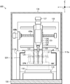
- FIG. 1 is a partially broken side sectional view schematically showing an outline of the overall configuration of a machine tool according to an embodiment of the present invention.
- FIG. 2 is a front sectional view schematically showing the outline of the entire configuration of the machine tool as viewed from line 2-2 shown in FIG. It is a rear view which shows typically the outline of the whole structure of the machine tool shown in FIG. It is a block diagram of the control system for controlling the action
- FIG. 2 is a partially cutaway side sectional view schematically showing a state at the time of tool replacement in the machine tool shown in FIG. 1.
- FIG. 2 is a partially broken side cross-sectional view schematically showing a state in which a workpiece is machined in a state in which a tool magazine unit in the machine tool shown in FIG. 1 is brought close to a machining head.
- FIG. 1 is a side sectional view schematically showing a configuration of a main part of a machine tool 100 according to the present invention.
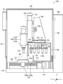
- FIG. 2 is a front cross-sectional view schematically showing the outline of the entire configuration of the machine tool 100 as viewed from line 2-2 shown in FIG.
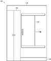
- FIG. 3 is a rear view schematically showing the outline of the overall configuration of the machine tool 100 shown in FIG.
- FIG. 4 is a block diagram of a control system for controlling the operation of the machine tool 100 shown in FIG.
- the machine tool 100 is a machine device that performs machining (for example, cutting, drilling, milling, boring, etc.) on the workpiece WK by computer control (NC control).
- NC control computer control
- the machine tool 100 includes a processing head 101.
- the processing head 101 is a mechanical device that detachably holds a processing tool 102 that performs a cutting process on the workpiece WK and that rotationally drives the held processing tool 102.
- the processing tool 102 is a cutting tool for metal processing such as a milling cutter, an end mill, a drill, or a tap that performs a cutting process on the workpiece WK.
- the machining head 101 is mainly configured by including a spindle 103, a spindle drive motor 104, and a head main body 105.
- the spindle 103 is a metal shaft-like component that incorporates a tool chuck (not shown) that holds the machining tool 102 in a freely magnetizable manner and is driven to rotate by a spindle drive motor 104.
- the spindle drive motor 104 is an actuator whose operation is controlled by an NC controller 140 described later.
- the head main body 105 is a metal structure that supports the spindle 103 and the spindle drive motor 104, respectively.
- the processing head 101 is supported by the movable support 106 via the head main body 105.
- the head support 106 is a metal structure that supports the head main body 105 in a state that it can be displaced in the Z-axis direction, which is the vertical direction in the figure, and is formed mainly extending in the Z-axis direction.
- the head support 106 includes a feed screw mechanism (not shown) for displacing the head main body 105 in the Z-axis direction and a Z-axis drive motor 107 for driving the feed screw mechanism.
- the feed screw mechanism includes a screw shaft (not shown) having a male screw formed on the outer peripheral surface of the shaft-like body and a movable body (not shown) having a female screw meshing with the male screw.
- the mechanical device is configured to drive the movable body linearly along the axial direction of the screw shaft by rotating the screw shaft.
- the Z-axis drive motor 107 is an actuator whose operation is controlled by the NC control device 140.
- the head support 106 is supported by the column 108.
- the column 108 is a metal structure that supports the head support 106 in a state in which the head support 106 can be displaced in the X-axis direction that is perpendicular to the paper surface of FIG. 1 orthogonal to the Z-axis direction (left-right direction in FIG. 2). Yes, mainly extending in the X-axis direction.
- the column 108 mainly includes a feed screw mechanism 108a for displacing the head support 106 in the X-axis direction and an X-axis drive motor 109b for driving the feed screw mechanism 109a.
- the X-axis drive motor 109b is an actuator whose operation is controlled by the NC control device 140.
- the column 108 is supported by two column bases 110a and 110b, respectively.
- the column bases 110a and 110b support the column 108 in a fixed manner and support the tool magazine 120 in a state displaceable in the Y-axis direction, which is the left-right direction in FIG. 1, which is orthogonal to the Z-axis direction and the X-axis direction, respectively.
- It is a pair of metal structures, and is mainly formed in a column shape extending in the Z-axis direction and the Y-axis direction. That is, the machine tool 100 is configured as a so-called gate type in which a column 108 is constructed on two column bases 110a and 110b.
- a tool magazine unit 120 is supported on the upper ends of the two column bases 110a and 110b.
- the tool magazine unit 120 is a mechanical device that can hold a plurality of processing tools 102 used by the processing head 101, and mainly includes a movable support base 121, a magazine cover 124, and a tool magazine 125.
- the movable support base 121 is a metal part that supports the magazine cover 124 and the tool magazine 125.
- the movable support base 121 is formed in a hollow cone shape extending from the lower side to the upper side in the drawing, and the upper end portion of the cone body is a flange shape. It is formed overhanging.
- the movable support base 121 is constructed such that an upper end portion that projects in a flange shape is slidable along the Y-axis direction between the two column bases 110a and 110b.
- the movable support base 121 rotationally drives a feed screw mechanism (not shown) for displacing the tool magazine 125 in the Y-axis direction, a magazine drive motor 122 for driving the feed screw mechanism, and the tool magazine 122.
- Index drive motors 123 are provided.
- the magazine drive motor 122 and the index drive motor 123 are actuators whose operations are controlled by the NC control device 140, respectively.
- the movable support base 121 is provided with a magazine cover 124.
- the magazine cover 124 is a plate-like component for preventing flying objects such as chips and cutting oil scattered by processing the workpiece WK from flying to the tool magazine 125.
- the work table 131 and the tool magazine described later are used as the magazine cover 124. It is provided in a state where it hangs down from the movable support base 121.
- the magazine cover 124 is provided with a pair of slide doors 124b that are paired on the left and right sides that can be opened and closed in the X-axis direction by an air cylinder 124a that is controlled by the NC controller 140.
- the tool magazine 125 is a mechanical device that detachably holds a processing tool 102 delivered to the processing head 101, and is configured by a plurality of chucks that hold a plurality of processing tools 102 one by one in the circumferential direction. ing.
- the tool magazine 125 is provided so as to hang down from the lower surface of the movable support base 121 while being connected to an indexing drive motor 123 provided in the movable support base 121.
- the base 130 is a metal structure that serves as a base for supporting each component and various devices of the machine tool 100, and is formed mainly extending in the Y-axis direction.
- the base 130 is provided with a receiving plate 131 below the column 108 and a work table 132 below the processing head 101.
- the receiving plate 131 is a metal plate-like component for preventing the machine tool 100 parts and equipment from being stained below the tool magazine 125.
- the work table 132 is a metal plate-like member that detachably holds the workpiece WK, and is formed in a planar view shape extending in the X-axis direction and the Y-axis direction.
- the work table 132 is supported by the feed screw mechanism 133 and the Y-axis drive motor 134 so as to be displaceable in the Y-axis direction with respect to the machining head 101.
- the feed screw mechanism 133 includes a screw shaft 133a in which a male screw is formed on the outer peripheral surface of the shaft-like body, and a movable body 133b in which a female screw meshing with the male screw 133a is formed.
- This is a mechanical device that drives the work table 132 provided with the movable body 133b linearly along the axial direction of the screw shaft 133a, that is, the Y-axis direction.
- the Y-axis drive motor 134 is an actuator whose operation is controlled by the NC control device 140.
- a bellows-shaped bottom cover 135 is provided between the work table 132 and the feed screw mechanism 133 to prevent the scattered matter from flying into the feed screw mechanism 133.
- the exterior cover 136 is provided around the base 130.
- the exterior cover 136 is a metal plate-like component that covers the processing head 101, the column 108, the work table 131, and the like on all sides and constitutes the housing of the machine tool 100.
- the exterior cover 136 has a front opening 137 formed on the front surface of the machine tool 100 and a magazine opening 138 formed on the rear surface of the machine tool 100.
- the front opening 137 is a portion that opens and closes so that an operator can perform work on the work table 132 and perform maintenance of the machine tool 100, and is configured by a double-open slide door.
- the magazine opening 138 is a portion that opens and closes for an operator to perform work on the tool magazine 125 and perform maintenance of the machine tool 100, and can be opened and closed as indicated by a broken line arrow in FIG. It consists of a sliding door.
- the NC control device 140 is provided on the back surface of the exterior cover 134.
- the NC control device 140 is constituted by a microcomputer including a CPU, a ROM, a RAM, etc., and comprehensively controls the entire operation of the machine tool 100, and a machining program (not shown) prepared by an operator (a so-called NC). (Numerical Control) program) controls the operations of the spindle drive motor 104, Z-axis drive motor 107, X-axis drive motor 109b, magazine drive motor 122, index drive motor 123, air cylinder 124a and Y-axis drive motor 134. Then, the machining head 101 is displaced relative to the workpiece WK to control the cutting of the workpiece WK.
- the NC control device 140 is provided with an operation panel 141 having a liquid crystal display device for inputting an instruction from an operator to the NC control device 140 and displaying an operation status of the NC control male value 140.
- the operation panel 141 is provided on the front surface of the exterior cover 134.
- the operator sets the workpiece WK on the work table 132 of the machine tool 100 and sets the processing tool 102 necessary for processing the workpiece WK in the tool magazine 125.
- the operator sets the workpiece WK on the work table 132 through the front opening 137 by opening the front opening 137 of the machine tool 100, and performs a plurality of processing through the magazine opening 138.
- NC program a machining program for three-dimensionally cutting the workpiece WK to the NC control device 140, and then executes the machining program to the NC control device 140.
- a command for selecting the machining tool 102 corresponding to the machining content and exchanging the tool with respect to the machining head 101 that is, Instructions for controlling the operation of the magazine drive motor 122, the index drive motor 123, and the air cylinder 124a are included.
- the NC control device 140 causes the spindle drive motor 104, the Z-axis drive motor 107, the X-axis drive motor 109b, the magazine drive motor 122, the index drive motor 123, the air cylinder 124a, and the Y-axis drive motor 134.
- the position of the tip (blade edge) of the machining tool 102 held by the machining head 101 with respect to the workpiece WK is changed.
- the workpiece WK held on the work table 132 is three-dimensionally cut by the processing tool 102.
- the NC control device 140 displaces the tool magazine unit 120 according to the machining status of the workpiece WK.
- Examples of displacement modes 1 and 2 of a typical tool magazine 120 are shown below.
- the standby position of the tool magazine 120 is a position where the processing tool 102, the workpiece WK, and the work table 132 that are being processed do not contact the tool magazine unit 120 (for example, in the machine tool 100). This is the farthest end position in the Y-axis direction (see FIG. 1), and the tool change position is the foremost part in the tool magazine 125 at a position directly below the machining head 101 with the machining head 101 located at the center in the X-axis direction.
- the retraction position of the work table 132 is the foremost end of the machine tool 100 in the Y-axis direction (see FIG. 5).
- the NC control device 140 can displace the tool magazine unit 120 together with the displacement of the work table 142 when exchanging the machining tool 102 with respect to the machining head 101. Specifically, as shown in FIG. 5, the NC control device 140 advances the tool magazine unit 120 from the standby position simultaneously with the displacement of the work table 132 to the retracted position when changing the tool with respect to the machining head 101. And can be positioned at the tool change position. Further, the NC control device 140 changes the tool with respect to the machining head 101 and then moves the tool magazine unit 120 backward from the tool change position to the standby position simultaneously with the displacement for returning the work table 132 from the retracted position to the machining position. be able to. According to these, the machine tool 100 can finish the tool change process earlier than the case where the tool magazine unit 120 is displaced after the displacement of the work table 132 is completed.
- the tool change process in the machining head 101 is performed by the NC control device 140 executing the following sub-steps 1 to 7.
- Substep 1 The NC control device 140 positions the machining head 101 at a position in the Z-axis direction where the tool can be changed.
- Substep 2 The NC control device 140 determines the chuck in the tool magazine 125 that holds the processing tool 102 held by the processing head 101.
- Substep 3 The NC control device 140 positions the tool magazine unit 120 at the alternate exchange position and grips the processing tool 102 by the tool magazine 124.
- Substep 4 The NC control device 140 raises the machining head 101 in the Z-axis direction and removes the machining tool 102 from the machining head 101.
- Sub-step 5 The NC control device 140 determines the chuck of the tool magazine 125 that holds the machining tool 102 newly held by the machining head 101.
- Substep 6 The NC control device 140 lowers the machining head 101 in the Z-axis direction and holds the new machining tool 102 on the machining head 101.
- Substep 7 The NC control device 140 retracts the tool magazine unit 120.
- the air cylinder 124a is moved when the distance between the machining head 101 and the magazine cover 124 reaches a predetermined amount. Is controlled to open the pair of left and right sliding doors 124 b so that the machining head 101 can pass through the magazine cover 124.
- the NC control device 140 when separating the magazine unit 120 from the processing head 101, sets the air cylinder 124a in the air cylinder 124a when the distance between the processing head 101 and the magazine cover 124 reaches a predetermined amount or more. By controlling the operation, the sliding door 124b is closed so that the scattered matter generated by the processing does not fly into the tool magazine 125.
- the chuck that holds the processing tool 102 in the tool magazine 125 by driving the index drive motor 123 can be selected before or during the displacement of the tool magazine unit 120.
- the NC control device 140 can change the displacement speed of the tool magazine 120 according to the relative position of the work table 142. For example, when the distance between the work table 142 and the tool magazine unit 120 in the Y-axis direction is greater than or equal to a predetermined distance, the NC controller 140 fast-forwards the tool magazine unit 120 and the distance is equal to the predetermined distance. If it is less, the displacement speed of the tool magazine unit 120 can be made equal to or lower than the displacement speed of the work table 142.
- the NC control device 140 can position the tool magazine unit 120 at a standby position corresponding to the position during processing of the workpiece WK. Specifically, as shown in FIG. 6, the NC control device 140 is closest to the workpiece WK or the work table 132 in a region that does not contact the workpiece WK and the work table 132 during the processing of the workpiece WK.
- the tool magazine unit 120 is positioned using the position as a standby position. In this case, the standby position of the tool magazine unit 120 may be specified in advance by the operator during the machining program, or the NC control device 140 may automatically calculate the machine program by executing the machining program on the computer. May be.
- the machine tool 100 may set the standby position of the tool magazine unit 120 throughout the machining process for the workpiece WK, or the tool magazine unit 120 for each machining tool 102 in the machining process for the workpiece WK.
- the standby position may be set. According to this, since the machine tool 100 can perform the tool change process from the standby position with the shortest distance with respect to the machining head 101, the tool change process can be completed early.
- the machine tool 100 operates the magazine drive motor 122 and the index drive motor 123 while the tool magazine unit 120 is positioned at the standby position during the processing of the workpiece WK.
- the operator can maintain the tool magazine unit 120.
- the operator can perform maintenance of the tool magazine unit 120 itself or the processing tool 102 held by the tool magazine 124 by opening the magazine opening 138 in a state where power supply to the tool magazine unit 120 is stopped. .
- the machine tool 100 can efficiently replace the machining tool 102 because the NC control device 140 can displace the tool magazine 124 by numerical control. Can be done.
- the machining head 101 is displaced in the X axis direction and the Z axis direction with respect to the work table 132, and the work table 132 is moved in the Y axis direction with respect to the machining head 101. It is configured to be displaced. That is, the Z-axis drive motor 107, the X-axis drive motor 109b, and the Y-axis drive motor 134 correspond to the processing tool displacement means according to the present invention.
- the processing tool displacing means is not necessarily limited to the above embodiment as long as the processing head 101 is configured to displace the processing head 101 relative to the work table 132.
- the machine tool 100 can be configured to displace the machining head 101 in the X-axis direction, the Y-axis direction, and the Z-axis direction with respect to the work table 132, and the work table 132 can be moved with respect to the machining head 101. It can also be configured to be displaced in the X-axis direction, the Y-axis direction, and the Z-axis direction.
- the machine tool 100 is configured such that the tool magazine unit 120 is displaced in the Y-axis direction with respect to the machining head 101. That is, the magazine drive motor 122 corresponds to the magazine displacement means according to the present invention.
- the magazine displacing means is not necessarily limited to the above embodiment as long as it is configured to displace the tool magazine 125 relative to the machining head 101. Therefore, the machine tool 100 can be configured to displace the machining head 101 in the Y-axis direction, further in the X-axis direction and the Z-axis direction with respect to the tool magazine 125.
- the tool magazine unit 120 includes the magazine cover 124.
- the magazine cover 124 is for preventing the flying material from flying to the tool magazine 125 and the processing tool 102 held by the tool magazine 125, and is unnecessary when the flying material is allowed to fly to these. It is.
- the magazine cover 124 is provided in the tool magazine unit 120 so as to be displaced integrally with the tool magazine 125.
- the magazine cover 124 may be provided separately from the tool magazine 125, for example, the column 108.
- the magazine opening 138 is provided on the back surface of the exterior cover 136.
- the magazine opening 138 is formed at a position where the tool magazine 125 can be accessed, in other words, on the wall surface other than the side facing the work table 132 in the periphery of the tool magazine 125, the magazine opening 138 is not necessarily in the above embodiment. It is not limited. Therefore, the magazine opening 138 can be provided on at least one of the left and right side surfaces of the exterior cover 136, for example. Further, the magazine opening 138 can be omitted when access to the tool magazine 125 is unnecessary.
- WK ... Workpiece 100 ... Machine tool, DESCRIPTION OF SYMBOLS 101 ... Processing head, 102 ... Processing tool, 103 ... Spindle, 104 ... Spindle drive motor, 105 ... Head main body, 106 ... Head support, 107 ... Z-axis drive motor, 108 ... Column, 109a ... Feed screw mechanism, 109b ... X-axis drive motor, 110a, 110b ... Column base, DESCRIPTION OF SYMBOLS 120 ... Tool magazine unit, 121 ... Movable support base, 122 ... Magazine drive motor, 123 ... Indexing drive motor, 124 ... Magazine cover, 124a ... Air cylinder, 124b ... Slide door, 125 ...
- Tool magazine DESCRIPTION OF SYMBOLS 130 ... Base, 131 ... Base plate, 132 ... Work table, 133 ... Feed screw mechanism, 133a ... Male screw, 133b ... Movable body, 134 ... Y-axis drive motor, 135 ... Bottom cover, 136 ... Exterior cover, 137 ... Front opening, 138 ... Magazine opening, 140: NC control device, 141: Operation panel.
Abstract
加工工具の交換処理を短時間に行うことにより加工効率が向上した工作機械の提供を目的とする。工作機械(100)は、被加工物(WK)を切削加工する加工工具(102)を保持する加工ヘッド(101)および被加工物(WK)を着脱自在に保持するワークテーブル(132)のほかに、ツールマガジン(125)、マガジン駆動モータ(122)およびNC制御装置(140)をそれぞれ備えている。ツールマガジン(125)は、加工ヘッド(101)が保持する加工工具(102)を複数保持する。マガジン駆動モータ(122)は、ツールマガジン(125)を加工ヘッド(101)に対して接近または離隔する方向に変位させる。NC制御装置(140)は、加工ヘッド(101)およびワークテーブル(132)のほかにマガジン駆動モータ(122)を数値制御することによってツールマガジン(125)を加工ヘッド(101)に対して相対変位させる。
Description
本発明は、加工工具を用いて被加工物を切削加工する工作機械に関する。
従来から、被加工物に対する加工工具の位置をNC(Numerical Control)制御によって変化させて被加工物を切削加工する工作機械が知られている。この場合、NC制御とは、被加工物に対する加工工具の位置や送り速度を数値情報で指令するプログラム制御方式である。例えば、下記特許文献1には、加工ヘッドを支持する門型コラムの両脚間に複数の加工工具を保持するツールマガジンが加工ヘッドに対して進退可能に設けられた門型マシニングセンタ(工作機械)が開示されている。
しかしながら、上記特許文献1に示された工作機械においては、ツールマガジンがシリンダによって所定の工具交換位置と待機位置との間を常に往復変位するため、加工ヘッドに対する加工工具の交換処理に時間が掛かって加工処理全体の効率が低いという問題があった。すなわち、従来の工作機械においては、ツールマガジンの変位時における位置や速度が制御対象とされていないため、変位するツールマガジンがワークテーブルや被加工物に衝突することを避けるためのワークテーブルの退避処理に時間が掛かるという問題がある。また、従来の工作機械においては、ツールマガジンは工作機械の加工エリアの外側に設定された待機位置に位置決めされるため、工具交換位置との間の変位に時間が掛かるという問題があった。
本発明は上記問題に対処するためなされたもので、その目的は、加工工具の交換処理を短時間に行うことによって加工効率を向上させることができる工作機械を提供することにある。
上記目的を達成するため、本発明の特徴は、被加工物を着脱自在に保持するワークテーブルと、被加工物を加工する加工工具を着脱自在に保持する加工ヘッドと、加工ヘッドをワークテーブルに対して相対的に変位させる加工工具変位手段と、加工ヘッドが保持する加工工具を複数着脱自在に保持することができるツールマガジンと、ツールマガジンを加工ヘッドに対して相対的に変位させるマガジン変位手段と、加工工具変位手段およびマガジン変位手段をそれぞれ数値制御して加工ヘッドおよびツールマガジンを相対変位させるNC制御装置とを備えたことにある。
このように構成した本発明の特徴によれば、工作機械は、NC制御装置がツールマガジンを数値制御により変位させることができるため、加工工具の交換処理を効率的に行うことができる。具体的には、工作機械は、ワークテーブルの退避処理または退避位置からの復帰処理と同時にツールマガジンを変位させることができるとともに、被加工物の加工中においてもツールマガジンを物理的な接触や衝突が生じない最低限の位置に位置決めすることによって工具交換位置との間の変位に要する時間を短縮することができる。また、工作機械は、ワークテーブルとの相対的な位置関係に応じてツールマガジンの変位の速度を変化、例えば、ワークテーブルとの間の距離が所定量以上の場合にはツールマガジンの変位速度を速めることによっても工具交換位置との間の変位に要する時間を短縮することができる。
また、本発明の他の特徴は、前記工作機械において、NC制御装置は、ワークテーブルとの相対的な位置に応じてマガジン変位手段の作動を制御してツールマガジンの位置決めを行うことにある。
このように構成した本発明の他の特徴によれば、工作機械は、NC制御装置がツールマガジンをワークテーブルとの相対的な位置関係に応じて位置決めするため、加工工具の交換処理を効率的に行うことができる。例えば、工作機械は、NC制御装置がワークテーブルとツールマガジンとの相対的な距離に応じて、より具体的には、ツールマガジンがワークテーブルに接触や衝突が生じない間隔を維持するようにツールマガジンの位置決め位置および変位速度を決定して作動させることができる。
また、本発明の他の特徴は、前記工作機械において、NC制御装置は、加工ヘッドに対して加工工具の交換処理を行う場合にワークテーブルの変位と同時にツールマガジンを変位させることにある。
このように構成した本発明の他の特徴によれば、工作機械は、NC制御装置が加工ヘッドに対して加工工具の交換処理を行う場合にワークテーブルの変位と同時にツールマガジンを変位させるため、加工工具の交換処理を効率的に行うことができる。
また、本発明の他の特徴は、前記工作機械において、さらに、ワークテーブルとツールマガジンとの間に開閉自在に設けられてツールマガジンが保持する加工工具への飛散物を阻止するマガジンカバーと、マガジンカバーを開閉するマガジンカバー開閉手段とを備え、NC制御装置は、開閉手段の作動を制御してマガジンカバーを開閉することにある。
このように構成した本発明の他の特徴によれば、工作機械は、ワークテーブルとツールマガジンとの間に開閉自在なマガジンカバーが設けられているため、被加工物の加工中におけるツールマガジンおよびこのツールマガジンが保持する加工工具への切粉や加工油などの飛散物の付着を防止することができる。
また、本発明の他の特徴は、前記工作機械において、マガジンカバーは、ツールマガジンに設けられて同ツールマガジンと一体的に変位することにある。
このように構成した本発明の他の特徴によれば、工作機械は、マガジンカバーがツールマガジンとともに一体的に変位するため、マガジンカバーが固定的に設けられている場合に比べてツールマガジンの変位のバリエーションが増加する。具体的には、工作機械は、被加工物の加工中であってもツールマガジンを変位させることができる。
また、本発明の他の特徴は、前記工作機械において、さらに、ワークテーブルおよびツールマガジンの周囲を囲む外装カバーを備え、外装カバーは、ツールマガジンの周囲のうちのワークテーブルに対向する側以外の壁面に開閉自在のマガジン開口部が設けられていることにある。
このように構成した本発明の他の特徴によれば、工作機械は、ワークテーブルおよびツールマガジンの周囲を囲む外装カバーを備えるとともに、この外装カバーはワークテーブルに対向する側以外の壁面に開閉自在のマガジンス開口部が設けられているため、被加工物の加工中であっても作業者がツールマガジンのメンテナンスやツールマガジンに対して加工工具の交換などの作業を行うことができる。
(工作機械100の構成)
以下、本発明に係る工作機械の一実施形態について図面を参照しながら説明する。図1は、本発明に係る工作機械100の主要部の構成を模式的に示した側面断面図である。また、図2は、図1に示す2-2線から見た工作機械100の全構成の概略を模式的に示す正面断面図である。また、図3は、図1に示す工作機械100の全体構成の概略を模式的に示す背面図である。また、図4は、図1に示す工作機械100の作動を制御するための制御システムのブロック図である。なお、本明細書において参照する図は、本発明の理解を容易にするために一部の構成要素を誇張して表わすなど模式的に表している。このため、各構成要素間の寸法や比率などは異なっていることがある。この工作機械100は、コンピュータ制御(NC制御)によって被加工物WKに対して機械加工(例えば、切削、穴開け、フライス削り、中ぐりなど)を行う機械装置である。
以下、本発明に係る工作機械の一実施形態について図面を参照しながら説明する。図1は、本発明に係る工作機械100の主要部の構成を模式的に示した側面断面図である。また、図2は、図1に示す2-2線から見た工作機械100の全構成の概略を模式的に示す正面断面図である。また、図3は、図1に示す工作機械100の全体構成の概略を模式的に示す背面図である。また、図4は、図1に示す工作機械100の作動を制御するための制御システムのブロック図である。なお、本明細書において参照する図は、本発明の理解を容易にするために一部の構成要素を誇張して表わすなど模式的に表している。このため、各構成要素間の寸法や比率などは異なっていることがある。この工作機械100は、コンピュータ制御(NC制御)によって被加工物WKに対して機械加工(例えば、切削、穴開け、フライス削り、中ぐりなど)を行う機械装置である。
工作機械100は、加工ヘッド101を備えている。加工ヘッド101は、被加工物WKに対して切削加工を行う加工工具102を着脱自在に保持するとともに保持した加工工具102を回転駆動する機械装置である。加工工具102は、被加工物WKに対して切削加工を行うフライス、エンドミル、ドリルまたはタップなどの金属加工用の刃物である。この加工ヘッド101は、主として、スピンドル103、スピンドル駆動モータ104およびヘッド本体部105をそれぞれ備えて構成されている。
スピンドル103は、加工工具102を着磁自在に保持する図示しないツールチャックを内蔵してスピンドル駆動モータ104によって回転駆動する金属製の軸状部品である。スピンドル駆動モータ104は、後述するNC制御装置140によって作動が制御されるアクチュエータである。ヘッド本体部105は、スピンドル103およびスピンドル駆動モータ104をそれぞれ支持する金属製の構造体である。この加工ヘッド101は、ヘッド本体部105を介して可動支持体106に支持されている。
ヘッド支持体106は、ヘッド本体部105を図示上下方向であるZ軸方向に変位可能な状態で支持する金属製の構造体であり、主としてZ軸方向に延びて形成されている。このヘッド支持体106は、ヘッド本体部105をZ軸方向に変位させるための図示しない送りネジ機構およびこの送りネジ機構を駆動するためのZ軸駆動モータ107をそれぞれ備えている。この場合、送りネジ機構とは、軸状体の外周面に雄ネジが形成されたネジ軸(図示せず)とこの雄ネジに噛み合う雌ネジが形成された可動体(図示せず)とで構成されており、ネジ軸を回転駆動させることにより可動体をネジ軸の軸線方向に沿って直線的に駆動させる機械装置である。Z軸駆動モータ107は、NC制御装置140によって作動が制御されるアクチュエータである。このヘッド支持体106は、コラム108に支持されている。
コラム108は、ヘッド支持体106をZ軸方向に直交する図1の紙面に対して垂直方向(図2において左右方向)であるX軸方向に変位可能な状態で支持する金属製の構造体であり、主としてX軸方向に延びて形成されている。このコラム108は、主として、ヘッド支持体106をX軸方向に変位させるための送りネジ機構108aおよびこの送りネジ機構109aを駆動するためのX軸駆動モータ109bをそれぞれ備えている。X軸駆動モータ109bは、NC制御装置140によって作動が制御されるアクチュエータである。このコラム108は、2つのコラムベース110a,110bにそれぞれ支持されている。
コラムベース110a,110bは、コラム108を固定的に支持するとともにツールマガジン120をZ軸方向およびX軸方向にそれぞれ直交する図1の左右方向であるY軸方向に変位可能な状態で支持する左右一対の金属製の構造体であり、主としてZ軸方向およびY軸方向にそれぞれ延びる柱状に形成されている。すなわち、工作機械100は、2つのコラムベース110a,110b上にコラム108が架設された所謂門型で構成されている。これら2つのコラムベース110a,110bの各上端部には、ツールマガジンユニット120が支持されている。
ツールマガジンユニット120は、加工ヘッド101が使用する加工工具102を複数保持することができる機械装置であり、主として、可動支持ベース121、マガジンカバー124およびツールマガジン125をそれぞれ備えている。可動支持ベース121は、マガジンカバー124およびツールマガジン125を支持する金属製の部品であり、図示下方から上方に向かって広がる空洞の錐体状に形成されるとともに同錐体の上端部がフランジ状に張り出して形成されている。この可動支持ベース121は、フランジ状に張り出した上端部が2つのコラムベース110a,110b間にY軸方向に沿って摺動自在な状態で架設されている。
そして、この可動支持ベース121には、ツールマガジン125をY軸方向に変位させるための図示しない送りネジ機構、この送りネジ機構を駆動するためのマガジン駆動モータ122、およびツールマガジン122を回転駆動するための割出駆動モータ123をそれぞれ備えている。マガジン駆動モータ122および割出駆動モータ123は、NC制御装置140によってそれぞれ作動が制御されるアクチュエータである。また、可動支持ベース121には、マガジンカバー124が設けられている。
マガジンカバー124は、被加工物WKの加工によって飛散する切粉や切削油などの飛散物のツールマガジン125への飛来を防止するための板状の部品であり、後述するワークテーブル131とツールマガジン125との間で可動支持ベース121から下垂した状態で設けられている。このマガジンカバー124は、NC制御装置140によって作動制御されるエアシリンダ124aによってX軸方向に開閉可能な左右2つで一対を構成するスライドドア124bをそれぞれ備えている。
ツールマガジン125は、加工ヘッド101に対して受け渡しする加工工具102を着脱自在に保持する機械装置であり、複数の加工工具102を1つずつ保持するチャックが円周方向に複数配置されて構成されている。このツールマガジン125は、可動支持ベース121内に設けられた割出駆動モータ123に連結された状態で可動支持ベース121の下面から下垂して設けられている。
そして、これらの2つのコラムベース110a,110bは、基台130上に起立した状態で取り付けられている。基台130は、工作機械100の各構成部品および各種機器を支持する土台となる金属製の構造体であり、主としてY軸方向に延びて形成されている。この基台130には、コラム108の下方に受け板131が設けられるとともに加工ヘッド101の下方にワークテーブル132が設けられる。受け板131は、ツールマガジン125の下方における工作機械100の部品や機器の汚損を防止するための金属製の板状部品である。
ワークテーブル132は、被加工物WKを着脱自在に保持する金属製の板状部材であり、X軸方向およびY軸方向に延びる平面視方形状に形成されている。このワークテーブル132は、送りネジ機構133およびY軸駆動モータ134によって加工ヘッド101に対してY軸方向に変位可能な状態で支持されている。送りネジ機構133は、軸状体の外周面に雄ネジが形成されたネジ軸133aとこの雄ネジ133aに噛み合う雌ネジが形成された可動体133bとで構成されており、ネジ軸133aを回転駆動させることにより可動体133bが設けられたワークテーブル132をネジ軸133aの軸線方向、すなわちY軸方向に沿って直線的に駆動させる機械装置である。Y軸駆動モータ134は、NC制御装置140によって作動が制御されるアクチュエータである。また、ワークテーブル132と送りネジ機構133との間には、送りネジ機構133への飛散物の飛来を防止するための蛇腹状の底部カバー135が設けられている。
基台130の周囲には外装カバー136が設けられている。外装カバー136は、加工ヘッド101、コラム108およびワークテーブル131などを四方および上方を覆って工作機械100の筐体を構成する金属製の板状部品である。この外装カバー136には、工作機械100の前面となる面に前面開口部137が形成されるとともに、工作機械100の背面となる面にマガジン開口部138が形成されている。前面開口部137は、作業者がワークテーブル132に対して作業を行なったり、工作機械100のメンテナンスを行うために開閉する部分であり、両開きのスライドドアによって構成されている。また、マガジン開口部138は、作業者がツールマガジン125に対して作業を行なったり、工作機械100のメンテナンスを行うために開閉する部分であり、図3において破線矢印に示すように、開閉可能なスライドドアによって構成されている。
また、外装カバー134における背面には、NC制御装置140が設けられている。NC制御装置140は、CPU、ROM、RAMなどからなるマイクロコンピュータによって構成されており、工作機械100の全体の作動を総合的に制御するとともに、作業者によって用意される図示しない加工プログラム(所謂NC(Numerical Control)プログラム)に従ってスピンドル駆動モータ104、Z軸駆動モータ107、X軸駆動モータ109b、マガジン駆動モータ122、割出駆動モータ123、エアシリンダ124aおよびY軸駆動モータ134の各作動を制御して被加工物WKに対して加工ヘッド101を相対変位させることにより被加工物WKへの切削加工を制御する。また、このNC制御装置140には、NC制御装置140に対して作業者からの指示を入力するとともにNC制御雄値140の作動状況を表示する液晶表示装置を備えた操作パネル141を備えている。この操作パネル141は、外装カバー134の前面に設けられている。
(工作機械100の作動)
次に、上記のように構成した工作機械100の作動について説明する。まず、作業者、工作機械100の電源をONにする。これにより、工作機械100は、NC制御装置140内のROMに予め記憶されている図示しない所定の制御プログラムを実行することにより、加工ヘッド101を原点復帰させた後、作業者からの指示を待つ待機状態となる。
次に、上記のように構成した工作機械100の作動について説明する。まず、作業者、工作機械100の電源をONにする。これにより、工作機械100は、NC制御装置140内のROMに予め記憶されている図示しない所定の制御プログラムを実行することにより、加工ヘッド101を原点復帰させた後、作業者からの指示を待つ待機状態となる。
次に、作業者は、工作機械100のワークテーブル132上に被加工物WKをセットするとともに、この被加工物WKの加工に必要な加工工具102をツールマガジン125にセットする。この場合、作業者は、工作機械100の前面開口部137を開くことによりこの前面開口部137を介して被加工物WKをワークテーブル132にセットするとともに、マガジン開口部138を介して複数の加工工具102をそれぞれツールマガジン125にセットする
次に、作業者は、被加工物WKに対して3次元的に切削加工するための加工プログラム(NCプログラム)をNC制御装置140に入力した後、この加工プログラムの実行をNC制御装置140に指示する。この場合、被加工物WKに対して3次元的な切削加工を行うための加工プログラムには、加工内容に応じた加工工具102を選択して加工ヘッド101に対して工具交換を行う指令、すなわち、マガジン駆動モータ122、割出駆動モータ123およびエアシリンダ124aの作動を制御する指令が含まれている。
この指示に応答して、NC制御装置140は、スピンドル駆動モータ104、Z軸駆動モータ107、X軸駆動モータ109b、マガジン駆動モータ122、割出駆動モータ123、エアシリンダ124aおよびY軸駆動モータ134の各作動を制御することにより被加工物WKに対する加工ヘッド101が保持する加工工具102の先端部(刃先)の位置を変化させる。これにより、ワークテーブル132上に保持された被加工物WKは、加工工具102によって3次元的に切削加工される。
この被加工物WKに対する切削加工においては、NC制御装置140は、被加工物WKの加工状況に応じてツールマガジンユニット120を変位させる。以下に典型的なツールマガジン120の変位態様例1,2をそれぞれ示す。なお、以下の変形態様例においては、ツールマガジン120の待機位置とは加工中の加工工具102、被加工物WKおよびワークテーブル132がそれぞれツールマガジンユニット120に接触しない位置(例えば、工作機械100におけるY軸方向の最奥端位置(図1参照))であり、工具交換位置とは加工ヘッド101がX軸方向中央部に位置した状態で加工ヘッド101の真下の位置にツールマガジン125における最前部のチャックを位置させる位置であり(図5参照)、ワークテーブル132の退避位置とは工作機械100におけるY軸方向の最前端である(図5参照)。
(変位態様例1)
NC制御装置140は、加工ヘッド101に対する加工工具102の工具交換時にワークテーブル142の変位とともにツールマガジンユニット120を変位させることができる。具体的には、NC制御装置140は、図5に示すように、加工ヘッド101に対して工具交換を行う際、ワークテーブル132の退避位置への変位と同時にツールマガジンユニット120を待機位置から前進させて工具交換位置に位置決めすることができる。また、NC制御装置140は、加工ヘッド101に対して工具交換を行った後、ワークテーブル132を退避位置から加工位置に復帰させる変位と同時にツールマガジンユニット120を工具交換位置から待機位置に後退させることができる。これらによれば、工作機械100は、ワークテーブル132の変位の完了の後にツールマガジンユニット120を変位させる場合に比べて早期に工具交換処理を終えることができる。
NC制御装置140は、加工ヘッド101に対する加工工具102の工具交換時にワークテーブル142の変位とともにツールマガジンユニット120を変位させることができる。具体的には、NC制御装置140は、図5に示すように、加工ヘッド101に対して工具交換を行う際、ワークテーブル132の退避位置への変位と同時にツールマガジンユニット120を待機位置から前進させて工具交換位置に位置決めすることができる。また、NC制御装置140は、加工ヘッド101に対して工具交換を行った後、ワークテーブル132を退避位置から加工位置に復帰させる変位と同時にツールマガジンユニット120を工具交換位置から待機位置に後退させることができる。これらによれば、工作機械100は、ワークテーブル132の変位の完了の後にツールマガジンユニット120を変位させる場合に比べて早期に工具交換処理を終えることができる。
なお、加工ヘッド101における工具交換処理は、NC制御装置140が以下のサブステップ1~7を実行することによって行われる。
サブステップ1:NC制御装置140は、加工ヘッド101を工具交換可能なZ軸方向の位置に位置決めする。
サブステップ2:NC制御装置140は、加工ヘッド101が保持する加工工具102を掴むツールマガジン125におけるチャックを割り出す。
サブステップ3:NC制御装置140は、ツールマガジンユニット120を交互交換位置に位置決めしてツールマガジン124によって加工工具102を把持させる。
サブステップ4:NC制御装置140は、加工ヘッド101をZ軸方向に上昇させて加工工具102を加工ヘッド101から抜く。
サブステップ5:NC制御装置140は、加工ヘッド101が新たに保持する加工工具102を保持するツールマガジン125のチャックを割り出す。
サブステップ6:NC制御装置140は、加工ヘッド101をZ軸方向に下降させて新たな加工工具102を加工ヘッド101に保持させる。
サブステップ7:NC制御装置140は、ツールマガジンユニット120を退避させる。
そして、この工具交換処理においては、NC制御装置140は、ツールマガジンユニット120を加工ヘッド101側に変位させる際、加工ヘッド101とマガジンカバー124との間隔が所定量に達したときにエアシリンダ124aの作動を制御することにより左右一対のスライドドア124bを開いて加工ヘッド101がマガジンカバー124を通過できるようにする。また、NC制御装置140は、工具交換処理後においては、マガジンユニット120を加工ヘッド101から離隔させる際、加工ヘッド101とマガジンカバー124との間隔が所定量以上に達したときにエアシリンダ124aの作動を制御することによりスライドドア124bを閉じて加工によって生じる飛散物がツールマガジン125に飛散しないようにする。なお、割出駆動モータ123の駆動によるツールマガジン125における加工工具102を保持するチャックの選択は、ツールマガジンユニット120の変位の前または変位中に行うことができる。
このような、ワークテーブル142の変位に同期したツールマガジンユニット120を変位は、加工プログラムにマガジン駆動モータ122、割出駆動モータ123およびエアシリンダ124aの各作動を制御する指令を含ませておくことで実現できる。なお、この場合、NC制御装置140は、ツールマガジン120の変位速度をワークテーブル142の相対位置に応じて変化させることができる。例えば、NC制御装置140は、ワークテーブル142とツールマガジンユニット120とのY軸方向での間隔が所定の間隔以上に離れている場合にはツールマガジンユニット120を早送りするとともに前記間隔が所定の間隔未満の場合にはツールマガジンユニット120の変位速度をワークテーブル142の変位速度以下にすることができる。
(変位態様例2)
NC制御装置140は、被加工物WKの加工中における位置に応じた待機位置にツールマガジンユニット120を位置決めすることができる。具体的には、NC制御装置140は、図6に示すように、被加工物WKの加工中における被加工物WKおよびワークテーブル132に接触しない領域における最も被加工物WKまたはワークテーブル132に近い位置を待機位置としてツールマガジンユニット120を位置決めする。この場合、ツールマガジンユニット120の待機位置は、作業者が予め加工プログラム中に指示しておいてもよいし、NC制御装置140が加工プログラムをコンピュータ上で実行して自動的に算出するようにしてもよい。これらの場合、工作機械100は、被加工物WKに対する加工工程全体でツールマガジンユニット120の待機位置を設定してもよいし、被加工物WKに対する加工工程における加工工具102ごとにツールマガジンユニット120の待機位置を設定してもよい。これによれば、工作機械100は、加工ヘッド101に対して最短距離の待機位置から工具交換処理を行なえるため、早期に工具交換処理を終えることができる。
NC制御装置140は、被加工物WKの加工中における位置に応じた待機位置にツールマガジンユニット120を位置決めすることができる。具体的には、NC制御装置140は、図6に示すように、被加工物WKの加工中における被加工物WKおよびワークテーブル132に接触しない領域における最も被加工物WKまたはワークテーブル132に近い位置を待機位置としてツールマガジンユニット120を位置決めする。この場合、ツールマガジンユニット120の待機位置は、作業者が予め加工プログラム中に指示しておいてもよいし、NC制御装置140が加工プログラムをコンピュータ上で実行して自動的に算出するようにしてもよい。これらの場合、工作機械100は、被加工物WKに対する加工工程全体でツールマガジンユニット120の待機位置を設定してもよいし、被加工物WKに対する加工工程における加工工具102ごとにツールマガジンユニット120の待機位置を設定してもよい。これによれば、工作機械100は、加工ヘッド101に対して最短距離の待機位置から工具交換処理を行なえるため、早期に工具交換処理を終えることができる。
また、上記各変位態様例1,2においては、工作機械100は、被加工物WKの加工中にツールマガジンユニット120が待機位置に位置する状態でマガジン駆動モータ122および割出駆動モータ123の作動を停止させることにより作業者にツールマガジンユニット120のメンテナンスをさせることができる。この場合、作業者は、ツールマガジンユニット120への動力供給の停止状態においてマガジン開口部138を開口することによってツールマガジンユニット120自体やツールマガジン124が保持する加工工具102のメンテナンスを行うことができる。
上記作動説明からも理解できるように、上記実施形態によれば、工作機械100は、NC制御装置140がツールマガジン124を数値制御により変位させることができるため、加工工具102の交換処理を効率的に行うことができる。
さらに、本発明の実施にあたっては、上記実施形態に限定されるものではなく、本発明の目的を逸脱しない限りにおいて種々の変更が可能である。
例えば、上記実施形態においては、工作機械100は、加工ヘッド101がワークテーブル132に対してX軸方向およびZ軸方向にそれぞれ変位するとともに、ワークテーブル132が加工ヘッド101に対してY軸方向に変位するように構成されている。すなわち、Z軸駆動モータ107、X軸駆動モータ109bおよびY軸駆動モータ134が本発明に係る加工工具変位手段に相当する。しかし、加工工具変位手段は、加工ヘッド101をワークテーブル132に対して相対的に変位させるよう構成されていれば、必ずしも上記実施形態に限定されるものではない。したがって、工作機械100は、加工ヘッド101をワークテーブル132に対してX軸方向、Y軸方向およびZ軸方向に変位させるように構成することもできるとともに、ワークテーブル132を加工ヘッド101に対してX軸方向、Y軸方向およびZ軸方向に変位させるように構成することもできる。
また、上記実施形態においては、工作機械100は、ツールマガジンユニット120が加工ヘッド101に対してY軸方向に変位するように構成されている。すなわち、マガジン駆動モータ122が本発明に係るマガジン変位手段に相当する。しかし、マガジン変位手段は、ツールマガジン125を加工ヘッド101に対して相対的に変位させるよう構成されていれば、必ずしも上記実施形態に限定されるものではない。したがって、工作機械100は、加工ヘッド101をツールマガジン125に対してY軸方向、さらには、X軸方向およびZ軸方向に変位させるように構成することもできる。
また、上記実施形態においては、ツールマガジンユニット120は、マガジンカバー124を備えて構成されている。しかし、マガジンカバー124は、ツールマガジン125およびツールマガジン125が保持する加工工具102への飛散物の飛来を防止するためのものであり、これらへの飛散物の飛来が許容される場合には不要である。また、上記実施形態においては、マガジンカバー124は、ツールマガジンユニット120に設けてツールマガジン125と一体的に変位するように構成した。しかし、マガジンカバー124は、ツールマガジン125とは別体、例えば、コラム108に固定的に設けることもできる。
また、上記実施形態においては、外装カバー136における背面にマガジン開口部138を設けた。しかし、マガジン開口部138は、ツールマガジン125にアクセスできる位置、換言すれば、ツールマガジン125の周囲のうちのワークテーブル132に対向する側以外の壁面に形成されていれば、必ずしも上記実施形態に限定されるものではない。したがって、マガジン開口部138は、例えば、外装カバー136における左右の側面の少なくとも一方に設けることもできる。また、マガジン開口部138は、ツールマガジン125へのアクセスが不要の場合には、省略することもできる。
WK…被加工物、
100…工作機械、
101…加工ヘッド、102…加工工具、103…スピンドル、104…スピンドル駆動モータ、105…ヘッド本体部、106…ヘッド支持体、107…Z軸駆動モータ、108…コラム、109a…送りネジ機構、109b…X軸駆動モータ、110a,110b…コラムベース、
120…ツールマガジンユニット、121…可動支持ベース、122…マガジン駆動モータ、123…割出駆動モータ、124…マガジンカバー、124a…エアシリンダ、124b…スライドドア、125…ツールマガジン、
130…基台、131…受け板、132…ワークテーブル、133…送りネジ機構、133a…雄ネジ、133b…可動体、134…Y軸駆動モータ、135…底部カバー、136…外装カバー、137…前面開口部、138…マガジン開口部、
140…NC制御装置、141…操作パネル。
Claims (6)
- 被加工物を着脱自在に保持するワークテーブルと、
前記被加工物を加工する加工工具を着脱自在に保持する加工ヘッドと、
前記加工ヘッドを前記ワークテーブルに対して相対的に変位させる加工工具変位手段と、
前記加工ヘッドが保持する前記加工工具を複数着脱自在に保持することができるツールマガジンと、
前記ツールマガジンを前記加工ヘッドに対して相対的に変位させるマガジン変位手段と、
前記加工工具変位手段および前記マガジン変位手段をそれぞれ数値制御して前記加工ヘッドおよび前記ツールマガジンを相対変位させるNC制御装置とを備えたことを特徴とする工作機械。 - 請求項1に記載した工作機械において、
前記NC制御装置は、
前記ワークテーブルとの相対的な位置に応じて前記マガジン変位手段の作動を制御して前記ツールマガジンの位置決めを行うことを特徴とする工作機械。 - 請求項1または請求項2に記載した工作機械において、
前記NC制御装置は、
前記加工ヘッドに対して前記加工工具の交換処理を行う場合に前記ワークテーブルの変位と同時に前記ツールマガジンを変位させることを特徴とする工作機械。 - 請求項1ないし請求項3のうちのいずれか1つに記載した工作機械において、さらに、
前記ワークテーブルと前記ツールマガジンとの間に開閉自在に設けられて前記ツールマガジンが保持する前記加工工具への飛散物を阻止するマガジンカバーと、
前記マガジンカバーを開閉するマガジンカバー開閉手段とを備え、
前記NC制御装置は、
前記開閉手段の作動を制御して前記マガジンカバーを開閉することを特徴とする工作機械。 - 請求項4に記載した工作機械において、
前記マガジンカバーは、
前記ツールマガジンに設けられて同ツールマガジンと一体的に変位することを特徴とする工作機械。 - 請求項1ないし請求項5のうちのいずれか1つに記載した工作機械において、さらに、
前記ワークテーブルおよび前記ツールマガジンの周囲を囲む外装カバーを備え、
前記外装カバーは、
前記ツールマガジンの周囲のうちの前記ワークテーブルに対向する側以外の壁面に開閉自在のマガジン開口部が設けられていることを特徴とする工作機械。
Priority Applications (1)
| Application Number | Priority Date | Filing Date | Title |
|---|---|---|---|
| DE112015002391.7T DE112015002391T5 (de) | 2014-05-20 | 2015-03-25 | Werkzeugmaschine |
Applications Claiming Priority (2)
| Application Number | Priority Date | Filing Date | Title |
|---|---|---|---|
| JP2014-104052 | 2014-05-20 | ||
| JP2014104052A JP6376440B2 (ja) | 2014-05-20 | 2014-05-20 | 工作機械 |
Publications (1)
| Publication Number | Publication Date |
|---|---|
| WO2015178096A1 true WO2015178096A1 (ja) | 2015-11-26 |
Family
ID=54553773
Family Applications (1)
| Application Number | Title | Priority Date | Filing Date |
|---|---|---|---|
| PCT/JP2015/059076 WO2015178096A1 (ja) | 2014-05-20 | 2015-03-25 | 工作機械 |
Country Status (3)
| Country | Link |
|---|---|
| JP (1) | JP6376440B2 (ja) |
| DE (1) | DE112015002391T5 (ja) |
| WO (1) | WO2015178096A1 (ja) |
Cited By (3)
| Publication number | Priority date | Publication date | Assignee | Title |
|---|---|---|---|---|
| US10220478B2 (en) * | 2014-08-20 | 2019-03-05 | Fuji Corporation | Machining center |
| CN112705774A (zh) * | 2019-10-24 | 2021-04-27 | 东和株式会社 | 刀片更换装置、切断装置和切断物的制造方法 |
| CN112872430A (zh) * | 2021-01-27 | 2021-06-01 | 安庆金野新材料有限公司 | 一种高温合金金属材料的加工系统 |
Families Citing this family (5)
| Publication number | Priority date | Publication date | Assignee | Title |
|---|---|---|---|---|
| JP2018094673A (ja) * | 2016-12-13 | 2018-06-21 | ローランドディー.ジー.株式会社 | 加工システム及びプログラム |
| US10661313B2 (en) | 2017-01-05 | 2020-05-26 | Fives Cinetic Corp. | Multi-tool part cleaning machine |
| WO2019151147A1 (ja) * | 2018-01-31 | 2019-08-08 | 学校法人慶應義塾 | 工作機械、製造方法及びプログラム |
| US20230158622A1 (en) * | 2020-04-24 | 2023-05-25 | Dmg Mori Co., Ltd. | Processing machine |
| DE102021125634A1 (de) | 2021-10-04 | 2023-04-06 | Homag Bohrsysteme Gmbh | Werkzeugmaschine sowie Verfahren |
Citations (6)
| Publication number | Priority date | Publication date | Assignee | Title |
|---|---|---|---|---|
| JPS634583Y2 (ja) * | 1981-09-05 | 1988-02-05 | ||
| JPS6357039U (ja) * | 1986-10-02 | 1988-04-16 | ||
| JPH07171728A (ja) * | 1993-12-17 | 1995-07-11 | Showa Seiko Kk | 工作機械におけるマルチ・スピンドル同時ツール交換装置 |
| JPH1034473A (ja) * | 1996-07-17 | 1998-02-10 | Seiko Seiki Co Ltd | Cnc三次元加工ユニット |
| JP2004001229A (ja) * | 2003-07-29 | 2004-01-08 | Mori Seiki Co Ltd | Nc工作機械 |
| JP4443380B2 (ja) * | 2004-10-27 | 2010-03-31 | コマツNtc株式会社 | 工具マガジン装置およびこれを備えた立形マシニングセンタ |
Family Cites Families (4)
| Publication number | Priority date | Publication date | Assignee | Title |
|---|---|---|---|---|
| US5181898A (en) * | 1991-09-16 | 1993-01-26 | Cincinnati Milacron, Inc. | Cover assembly for multi-configurable machine tool |
| JP5575673B2 (ja) * | 2011-01-20 | 2014-08-20 | 光洋機械工業株式会社 | 自動工具交換装置 |
| JP5949182B2 (ja) * | 2012-06-05 | 2016-07-06 | ブラザー工業株式会社 | 工作機械 |
| JP2015123575A (ja) * | 2013-12-27 | 2015-07-06 | キヤノン電子株式会社 | 工作機械、及び工作機械用の工具マガジン |
-
2014
- 2014-05-20 JP JP2014104052A patent/JP6376440B2/ja active Active
-
2015
- 2015-03-25 DE DE112015002391.7T patent/DE112015002391T5/de active Pending
- 2015-03-25 WO PCT/JP2015/059076 patent/WO2015178096A1/ja active Application Filing
Patent Citations (6)
| Publication number | Priority date | Publication date | Assignee | Title |
|---|---|---|---|---|
| JPS634583Y2 (ja) * | 1981-09-05 | 1988-02-05 | ||
| JPS6357039U (ja) * | 1986-10-02 | 1988-04-16 | ||
| JPH07171728A (ja) * | 1993-12-17 | 1995-07-11 | Showa Seiko Kk | 工作機械におけるマルチ・スピンドル同時ツール交換装置 |
| JPH1034473A (ja) * | 1996-07-17 | 1998-02-10 | Seiko Seiki Co Ltd | Cnc三次元加工ユニット |
| JP2004001229A (ja) * | 2003-07-29 | 2004-01-08 | Mori Seiki Co Ltd | Nc工作機械 |
| JP4443380B2 (ja) * | 2004-10-27 | 2010-03-31 | コマツNtc株式会社 | 工具マガジン装置およびこれを備えた立形マシニングセンタ |
Cited By (3)
| Publication number | Priority date | Publication date | Assignee | Title |
|---|---|---|---|---|
| US10220478B2 (en) * | 2014-08-20 | 2019-03-05 | Fuji Corporation | Machining center |
| CN112705774A (zh) * | 2019-10-24 | 2021-04-27 | 东和株式会社 | 刀片更换装置、切断装置和切断物的制造方法 |
| CN112872430A (zh) * | 2021-01-27 | 2021-06-01 | 安庆金野新材料有限公司 | 一种高温合金金属材料的加工系统 |
Also Published As
| Publication number | Publication date |
|---|---|
| JP2015217492A (ja) | 2015-12-07 |
| DE112015002391T5 (de) | 2017-02-09 |
| JP6376440B2 (ja) | 2018-08-22 |
Similar Documents
| Publication | Publication Date | Title |
|---|---|---|
| JP6376440B2 (ja) | 工作機械 | |
| JP2015217492A5 (ja) | ||
| JP6604592B2 (ja) | 工作機械 | |
| TWI763939B (zh) | 車床 | |
| JPWO2019211887A1 (ja) | デフケースの加工機 | |
| JP2013202693A (ja) | 歯車加工機械 | |
| JP6209568B2 (ja) | 工作機械 | |
| JP6688829B2 (ja) | 工作機械 | |
| JP2002205209A (ja) | 三次元切削による穴開け加工方法 | |
| JP2013063488A (ja) | 立形マシニングセンタ | |
| JP2007094458A (ja) | 数値制御装置 | |
| JP2012161904A (ja) | 複合工具、加工方法および工作機械 | |
| JP2021102266A (ja) | 孔加工機および孔加工機を用いた楕円孔および内径変化孔の加工方法 | |
| KR101323890B1 (ko) | 터릿형 수직선반과 그의 제어 방법 및 이를 이용하여 제조된 베벨기어박스 | |
| JP2002331433A (ja) | 切削加工ユニット | |
| JP2017007061A (ja) | マシニングセンタ | |
| JP6754870B1 (ja) | 工作機械および制御方法 | |
| JP2002254408A (ja) | ドア部材などの加工装置 | |
| JP7085076B1 (ja) | 工作機械、制御方法、および制御プログラム | |
| US20230321731A1 (en) | Combined processing machine | |
| US20240075632A1 (en) | Assembly, apparatus and method for machining mechanical part | |
| JP2023019252A (ja) | 工作機械 | |
| JP6405115B2 (ja) | 孔加工方法、シリンダブロックの製造方法および孔加工機 | |
| JPS6158242B2 (ja) | ||
| JP2023009413A (ja) | 工作機械 |
Legal Events
| Date | Code | Title | Description |
|---|---|---|---|
| 121 | Ep: the epo has been informed by wipo that ep was designated in this application |
Ref document number: 15796111 Country of ref document: EP Kind code of ref document: A1 |
|
| WWE | Wipo information: entry into national phase |
Ref document number: 112015002391 Country of ref document: DE |
|
| 122 | Ep: pct application non-entry in european phase |
Ref document number: 15796111 Country of ref document: EP Kind code of ref document: A1 |