WO2015178096A1 - Machine-outil - Google Patents
Machine-outil Download PDFInfo
- Publication number
- WO2015178096A1 WO2015178096A1 PCT/JP2015/059076 JP2015059076W WO2015178096A1 WO 2015178096 A1 WO2015178096 A1 WO 2015178096A1 JP 2015059076 W JP2015059076 W JP 2015059076W WO 2015178096 A1 WO2015178096 A1 WO 2015178096A1
- Authority
- WO
- WIPO (PCT)
- Prior art keywords
- tool
- magazine
- machine tool
- machining
- work table
- Prior art date
Links
Images


Classifications
-
- B—PERFORMING OPERATIONS; TRANSPORTING
- B23—MACHINE TOOLS; METAL-WORKING NOT OTHERWISE PROVIDED FOR
- B23Q—DETAILS, COMPONENTS, OR ACCESSORIES FOR MACHINE TOOLS, e.g. ARRANGEMENTS FOR COPYING OR CONTROLLING; MACHINE TOOLS IN GENERAL CHARACTERISED BY THE CONSTRUCTION OF PARTICULAR DETAILS OR COMPONENTS; COMBINATIONS OR ASSOCIATIONS OF METAL-WORKING MACHINES, NOT DIRECTED TO A PARTICULAR RESULT
- B23Q1/00—Members which are comprised in the general build-up of a form of machine, particularly relatively large fixed members
- B23Q1/25—Movable or adjustable work or tool supports
- B23Q1/64—Movable or adjustable work or tool supports characterised by the purpose of the movement
-
- B—PERFORMING OPERATIONS; TRANSPORTING
- B23—MACHINE TOOLS; METAL-WORKING NOT OTHERWISE PROVIDED FOR
- B23Q—DETAILS, COMPONENTS, OR ACCESSORIES FOR MACHINE TOOLS, e.g. ARRANGEMENTS FOR COPYING OR CONTROLLING; MACHINE TOOLS IN GENERAL CHARACTERISED BY THE CONSTRUCTION OF PARTICULAR DETAILS OR COMPONENTS; COMBINATIONS OR ASSOCIATIONS OF METAL-WORKING MACHINES, NOT DIRECTED TO A PARTICULAR RESULT
- B23Q11/00—Accessories fitted to machine tools for keeping tools or parts of the machine in good working condition or for cooling work; Safety devices specially combined with or arranged in, or specially adapted for use in connection with, machine tools
- B23Q11/08—Protective coverings for parts of machine tools; Splash guards
-
- B—PERFORMING OPERATIONS; TRANSPORTING
- B23—MACHINE TOOLS; METAL-WORKING NOT OTHERWISE PROVIDED FOR
- B23Q—DETAILS, COMPONENTS, OR ACCESSORIES FOR MACHINE TOOLS, e.g. ARRANGEMENTS FOR COPYING OR CONTROLLING; MACHINE TOOLS IN GENERAL CHARACTERISED BY THE CONSTRUCTION OF PARTICULAR DETAILS OR COMPONENTS; COMBINATIONS OR ASSOCIATIONS OF METAL-WORKING MACHINES, NOT DIRECTED TO A PARTICULAR RESULT
- B23Q3/00—Devices holding, supporting, or positioning work or tools, of a kind normally removable from the machine
- B23Q3/155—Arrangements for automatic insertion or removal of tools, e.g. combined with manual handling
- B23Q3/157—Arrangements for automatic insertion or removal of tools, e.g. combined with manual handling of rotary tools
- B23Q3/15706—Arrangements for automatic insertion or removal of tools, e.g. combined with manual handling of rotary tools a single tool being inserted in a spindle directly from a storage device, i.e. without using transfer devices
-
- B—PERFORMING OPERATIONS; TRANSPORTING
- B23—MACHINE TOOLS; METAL-WORKING NOT OTHERWISE PROVIDED FOR
- B23Q—DETAILS, COMPONENTS, OR ACCESSORIES FOR MACHINE TOOLS, e.g. ARRANGEMENTS FOR COPYING OR CONTROLLING; MACHINE TOOLS IN GENERAL CHARACTERISED BY THE CONSTRUCTION OF PARTICULAR DETAILS OR COMPONENTS; COMBINATIONS OR ASSOCIATIONS OF METAL-WORKING MACHINES, NOT DIRECTED TO A PARTICULAR RESULT
- B23Q11/00—Accessories fitted to machine tools for keeping tools or parts of the machine in good working condition or for cooling work; Safety devices specially combined with or arranged in, or specially adapted for use in connection with, machine tools
- B23Q11/08—Protective coverings for parts of machine tools; Splash guards
- B23Q11/0891—Protective coverings for parts of machine tools; Splash guards arranged between the working area and the operator
-
- B—PERFORMING OPERATIONS; TRANSPORTING
- B23—MACHINE TOOLS; METAL-WORKING NOT OTHERWISE PROVIDED FOR
- B23Q—DETAILS, COMPONENTS, OR ACCESSORIES FOR MACHINE TOOLS, e.g. ARRANGEMENTS FOR COPYING OR CONTROLLING; MACHINE TOOLS IN GENERAL CHARACTERISED BY THE CONSTRUCTION OF PARTICULAR DETAILS OR COMPONENTS; COMBINATIONS OR ASSOCIATIONS OF METAL-WORKING MACHINES, NOT DIRECTED TO A PARTICULAR RESULT
- B23Q3/00—Devices holding, supporting, or positioning work or tools, of a kind normally removable from the machine
- B23Q3/155—Arrangements for automatic insertion or removal of tools, e.g. combined with manual handling
- B23Q3/1552—Arrangements for automatic insertion or removal of tools, e.g. combined with manual handling parts of devices for automatically inserting or removing tools
- B23Q3/15526—Storage devices; Drive mechanisms therefor
- B23Q2003/15537—Linearly moving storage devices
Definitions
- the present invention relates to a machine tool that cuts a workpiece using a processing tool.
- Patent Document 1 discloses a portal machining center (machine tool) in which a tool magazine for holding a plurality of machining tools is provided between both legs of a portal column that supports a machining head so as to be capable of moving back and forth with respect to the machining head. It is disclosed.
- the present invention has been made to cope with the above problems, and an object of the present invention is to provide a machine tool capable of improving the machining efficiency by performing the machining tool replacement process in a short time.
- the present invention is characterized by a work table that detachably holds a workpiece, a machining head that detachably holds a machining tool for machining the workpiece, and the machining head as a work table.
- a machining tool displacing means for relatively displacing the tool a tool magazine capable of detachably holding a plurality of machining tools held by the machining head, and a magazine displacing means for displacing the tool magazine relative to the machining head
- an NC control device for numerically controlling the machining tool displacement means and the magazine displacement means, respectively, to relatively displace the machining head and the tool magazine.
- the machine tool can efficiently perform the processing tool replacement process because the NC control device can displace the tool magazine by numerical control.
- the machine tool can displace the tool magazine at the same time as the work table retracting process or the returning process from the retracted position, and the tool magazine can be physically contacted or collided even while the workpiece is being processed.
- the time required for displacement from the tool change position can be shortened.
- the machine tool changes the displacement speed of the tool magazine according to the relative positional relationship with the work table. For example, when the distance from the work table is a predetermined amount or more, the displacement speed of the tool magazine is changed. The time required for displacement from the tool change position can also be shortened by increasing the speed.
- the NC control device controls the operation of the magazine displacing means according to the relative position with respect to the work table to position the tool magazine.
- the machine tool efficiently processes the processing tool replacement process because the NC control device positions the tool magazine according to the relative positional relationship with the work table. Can be done.
- the NC control device maintains a tool interval according to the relative distance between the work table and the tool magazine, more specifically, the tool magazine maintains an interval at which the work table does not contact or collide.
- the magazine positioning position and displacement speed can be determined and actuated.
- Another feature of the present invention is that, in the machine tool, the NC control device displaces the tool magazine simultaneously with the displacement of the work table when the machining tool is exchanged with respect to the machining head.
- the machine tool displaces the tool magazine simultaneously with the displacement of the work table when the NC control device performs a processing tool replacement process on the processing head.
- the processing tool replacement process can be performed efficiently.
- the machine tool further includes a magazine cover which is provided between the work table and the tool magazine so as to be freely opened and closed and prevents scattered matter from being scattered on the processing tool held by the tool magazine,
- a magazine cover opening / closing means for opening / closing the magazine cover is provided, and the NC controller is to open / close the magazine cover by controlling the operation of the opening / closing means.
- the machine tool is provided with a magazine cover that can be freely opened and closed between the work table and the tool magazine. It is possible to prevent scattered matter such as chips and processing oil from adhering to the processing tool held by the tool magazine.
- the magazine cover is provided on the tool magazine and is integrally displaced with the tool magazine.
- the machine tool displaces the tool magazine as compared with the case where the magazine cover is fixedly provided because the magazine cover is integrally displaced together with the tool magazine.
- the variation of increases. Specifically, the machine tool can displace the tool magazine even while the workpiece is being processed.
- the machine tool further includes an exterior cover surrounding the work table and the tool magazine, and the exterior cover is a part other than the side facing the work table in the periphery of the tool magazine.
- a magazine opening that can be freely opened and closed is provided on the wall surface.
- the machine tool includes an exterior cover surrounding the work table and the tool magazine, and the exterior cover can be opened and closed on a wall surface other than the side facing the work table. Therefore, even when the workpiece is being processed, the operator can perform operations such as maintenance of the tool magazine and replacement of the processing tool with respect to the tool magazine.
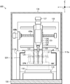
- FIG. 1 is a partially broken side sectional view schematically showing an outline of the overall configuration of a machine tool according to an embodiment of the present invention.
- FIG. 2 is a front sectional view schematically showing the outline of the entire configuration of the machine tool as viewed from line 2-2 shown in FIG. It is a rear view which shows typically the outline of the whole structure of the machine tool shown in FIG. It is a block diagram of the control system for controlling the action
- FIG. 2 is a partially cutaway side sectional view schematically showing a state at the time of tool replacement in the machine tool shown in FIG. 1.
- FIG. 2 is a partially broken side cross-sectional view schematically showing a state in which a workpiece is machined in a state in which a tool magazine unit in the machine tool shown in FIG. 1 is brought close to a machining head.
- FIG. 1 is a side sectional view schematically showing a configuration of a main part of a machine tool 100 according to the present invention.
- FIG. 2 is a front cross-sectional view schematically showing the outline of the entire configuration of the machine tool 100 as viewed from line 2-2 shown in FIG.
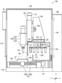
- FIG. 3 is a rear view schematically showing the outline of the overall configuration of the machine tool 100 shown in FIG.
- FIG. 4 is a block diagram of a control system for controlling the operation of the machine tool 100 shown in FIG.
- the machine tool 100 is a machine device that performs machining (for example, cutting, drilling, milling, boring, etc.) on the workpiece WK by computer control (NC control).
- NC control computer control
- the machine tool 100 includes a processing head 101.
- the processing head 101 is a mechanical device that detachably holds a processing tool 102 that performs a cutting process on the workpiece WK and that rotationally drives the held processing tool 102.
- the processing tool 102 is a cutting tool for metal processing such as a milling cutter, an end mill, a drill, or a tap that performs a cutting process on the workpiece WK.
- the machining head 101 is mainly configured by including a spindle 103, a spindle drive motor 104, and a head main body 105.
- the spindle 103 is a metal shaft-like component that incorporates a tool chuck (not shown) that holds the machining tool 102 in a freely magnetizable manner and is driven to rotate by a spindle drive motor 104.
- the spindle drive motor 104 is an actuator whose operation is controlled by an NC controller 140 described later.
- the head main body 105 is a metal structure that supports the spindle 103 and the spindle drive motor 104, respectively.
- the processing head 101 is supported by the movable support 106 via the head main body 105.
- the head support 106 is a metal structure that supports the head main body 105 in a state that it can be displaced in the Z-axis direction, which is the vertical direction in the figure, and is formed mainly extending in the Z-axis direction.
- the head support 106 includes a feed screw mechanism (not shown) for displacing the head main body 105 in the Z-axis direction and a Z-axis drive motor 107 for driving the feed screw mechanism.
- the feed screw mechanism includes a screw shaft (not shown) having a male screw formed on the outer peripheral surface of the shaft-like body and a movable body (not shown) having a female screw meshing with the male screw.
- the mechanical device is configured to drive the movable body linearly along the axial direction of the screw shaft by rotating the screw shaft.
- the Z-axis drive motor 107 is an actuator whose operation is controlled by the NC control device 140.
- the head support 106 is supported by the column 108.
- the column 108 is a metal structure that supports the head support 106 in a state in which the head support 106 can be displaced in the X-axis direction that is perpendicular to the paper surface of FIG. 1 orthogonal to the Z-axis direction (left-right direction in FIG. 2). Yes, mainly extending in the X-axis direction.
- the column 108 mainly includes a feed screw mechanism 108a for displacing the head support 106 in the X-axis direction and an X-axis drive motor 109b for driving the feed screw mechanism 109a.
- the X-axis drive motor 109b is an actuator whose operation is controlled by the NC control device 140.
- the column 108 is supported by two column bases 110a and 110b, respectively.
- the column bases 110a and 110b support the column 108 in a fixed manner and support the tool magazine 120 in a state displaceable in the Y-axis direction, which is the left-right direction in FIG. 1, which is orthogonal to the Z-axis direction and the X-axis direction, respectively.
- It is a pair of metal structures, and is mainly formed in a column shape extending in the Z-axis direction and the Y-axis direction. That is, the machine tool 100 is configured as a so-called gate type in which a column 108 is constructed on two column bases 110a and 110b.
- a tool magazine unit 120 is supported on the upper ends of the two column bases 110a and 110b.
- the tool magazine unit 120 is a mechanical device that can hold a plurality of processing tools 102 used by the processing head 101, and mainly includes a movable support base 121, a magazine cover 124, and a tool magazine 125.
- the movable support base 121 is a metal part that supports the magazine cover 124 and the tool magazine 125.
- the movable support base 121 is formed in a hollow cone shape extending from the lower side to the upper side in the drawing, and the upper end portion of the cone body is a flange shape. It is formed overhanging.
- the movable support base 121 is constructed such that an upper end portion that projects in a flange shape is slidable along the Y-axis direction between the two column bases 110a and 110b.
- the movable support base 121 rotationally drives a feed screw mechanism (not shown) for displacing the tool magazine 125 in the Y-axis direction, a magazine drive motor 122 for driving the feed screw mechanism, and the tool magazine 122.
- Index drive motors 123 are provided.
- the magazine drive motor 122 and the index drive motor 123 are actuators whose operations are controlled by the NC control device 140, respectively.
- the movable support base 121 is provided with a magazine cover 124.
- the magazine cover 124 is a plate-like component for preventing flying objects such as chips and cutting oil scattered by processing the workpiece WK from flying to the tool magazine 125.
- the work table 131 and the tool magazine described later are used as the magazine cover 124. It is provided in a state where it hangs down from the movable support base 121.
- the magazine cover 124 is provided with a pair of slide doors 124b that are paired on the left and right sides that can be opened and closed in the X-axis direction by an air cylinder 124a that is controlled by the NC controller 140.
- the tool magazine 125 is a mechanical device that detachably holds a processing tool 102 delivered to the processing head 101, and is configured by a plurality of chucks that hold a plurality of processing tools 102 one by one in the circumferential direction. ing.
- the tool magazine 125 is provided so as to hang down from the lower surface of the movable support base 121 while being connected to an indexing drive motor 123 provided in the movable support base 121.
- the base 130 is a metal structure that serves as a base for supporting each component and various devices of the machine tool 100, and is formed mainly extending in the Y-axis direction.
- the base 130 is provided with a receiving plate 131 below the column 108 and a work table 132 below the processing head 101.
- the receiving plate 131 is a metal plate-like component for preventing the machine tool 100 parts and equipment from being stained below the tool magazine 125.
- the work table 132 is a metal plate-like member that detachably holds the workpiece WK, and is formed in a planar view shape extending in the X-axis direction and the Y-axis direction.
- the work table 132 is supported by the feed screw mechanism 133 and the Y-axis drive motor 134 so as to be displaceable in the Y-axis direction with respect to the machining head 101.
- the feed screw mechanism 133 includes a screw shaft 133a in which a male screw is formed on the outer peripheral surface of the shaft-like body, and a movable body 133b in which a female screw meshing with the male screw 133a is formed.
- This is a mechanical device that drives the work table 132 provided with the movable body 133b linearly along the axial direction of the screw shaft 133a, that is, the Y-axis direction.
- the Y-axis drive motor 134 is an actuator whose operation is controlled by the NC control device 140.
- a bellows-shaped bottom cover 135 is provided between the work table 132 and the feed screw mechanism 133 to prevent the scattered matter from flying into the feed screw mechanism 133.
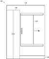
- the exterior cover 136 is provided around the base 130.
- the exterior cover 136 is a metal plate-like component that covers the processing head 101, the column 108, the work table 131, and the like on all sides and constitutes the housing of the machine tool 100.
- the exterior cover 136 has a front opening 137 formed on the front surface of the machine tool 100 and a magazine opening 138 formed on the rear surface of the machine tool 100.
- the front opening 137 is a portion that opens and closes so that an operator can perform work on the work table 132 and perform maintenance of the machine tool 100, and is configured by a double-open slide door.
- the magazine opening 138 is a portion that opens and closes for an operator to perform work on the tool magazine 125 and perform maintenance of the machine tool 100, and can be opened and closed as indicated by a broken line arrow in FIG. It consists of a sliding door.
- the NC control device 140 is provided on the back surface of the exterior cover 134.
- the NC control device 140 is constituted by a microcomputer including a CPU, a ROM, a RAM, etc., and comprehensively controls the entire operation of the machine tool 100, and a machining program (not shown) prepared by an operator (a so-called NC). (Numerical Control) program) controls the operations of the spindle drive motor 104, Z-axis drive motor 107, X-axis drive motor 109b, magazine drive motor 122, index drive motor 123, air cylinder 124a and Y-axis drive motor 134. Then, the machining head 101 is displaced relative to the workpiece WK to control the cutting of the workpiece WK.
- the NC control device 140 is provided with an operation panel 141 having a liquid crystal display device for inputting an instruction from an operator to the NC control device 140 and displaying an operation status of the NC control male value 140.
- the operation panel 141 is provided on the front surface of the exterior cover 134.
- the operator sets the workpiece WK on the work table 132 of the machine tool 100 and sets the processing tool 102 necessary for processing the workpiece WK in the tool magazine 125.
- the operator sets the workpiece WK on the work table 132 through the front opening 137 by opening the front opening 137 of the machine tool 100, and performs a plurality of processing through the magazine opening 138.
- NC program a machining program for three-dimensionally cutting the workpiece WK to the NC control device 140, and then executes the machining program to the NC control device 140.
- a command for selecting the machining tool 102 corresponding to the machining content and exchanging the tool with respect to the machining head 101 that is, Instructions for controlling the operation of the magazine drive motor 122, the index drive motor 123, and the air cylinder 124a are included.
- the NC control device 140 causes the spindle drive motor 104, the Z-axis drive motor 107, the X-axis drive motor 109b, the magazine drive motor 122, the index drive motor 123, the air cylinder 124a, and the Y-axis drive motor 134.
- the position of the tip (blade edge) of the machining tool 102 held by the machining head 101 with respect to the workpiece WK is changed.
- the workpiece WK held on the work table 132 is three-dimensionally cut by the processing tool 102.
- the NC control device 140 displaces the tool magazine unit 120 according to the machining status of the workpiece WK.
- Examples of displacement modes 1 and 2 of a typical tool magazine 120 are shown below.
- the standby position of the tool magazine 120 is a position where the processing tool 102, the workpiece WK, and the work table 132 that are being processed do not contact the tool magazine unit 120 (for example, in the machine tool 100). This is the farthest end position in the Y-axis direction (see FIG. 1), and the tool change position is the foremost part in the tool magazine 125 at a position directly below the machining head 101 with the machining head 101 located at the center in the X-axis direction.
- the retraction position of the work table 132 is the foremost end of the machine tool 100 in the Y-axis direction (see FIG. 5).
- the NC control device 140 can displace the tool magazine unit 120 together with the displacement of the work table 142 when exchanging the machining tool 102 with respect to the machining head 101. Specifically, as shown in FIG. 5, the NC control device 140 advances the tool magazine unit 120 from the standby position simultaneously with the displacement of the work table 132 to the retracted position when changing the tool with respect to the machining head 101. And can be positioned at the tool change position. Further, the NC control device 140 changes the tool with respect to the machining head 101 and then moves the tool magazine unit 120 backward from the tool change position to the standby position simultaneously with the displacement for returning the work table 132 from the retracted position to the machining position. be able to. According to these, the machine tool 100 can finish the tool change process earlier than the case where the tool magazine unit 120 is displaced after the displacement of the work table 132 is completed.
- the tool change process in the machining head 101 is performed by the NC control device 140 executing the following sub-steps 1 to 7.
- Substep 1 The NC control device 140 positions the machining head 101 at a position in the Z-axis direction where the tool can be changed.
- Substep 2 The NC control device 140 determines the chuck in the tool magazine 125 that holds the processing tool 102 held by the processing head 101.
- Substep 3 The NC control device 140 positions the tool magazine unit 120 at the alternate exchange position and grips the processing tool 102 by the tool magazine 124.
- Substep 4 The NC control device 140 raises the machining head 101 in the Z-axis direction and removes the machining tool 102 from the machining head 101.
- Sub-step 5 The NC control device 140 determines the chuck of the tool magazine 125 that holds the machining tool 102 newly held by the machining head 101.
- Substep 6 The NC control device 140 lowers the machining head 101 in the Z-axis direction and holds the new machining tool 102 on the machining head 101.
- Substep 7 The NC control device 140 retracts the tool magazine unit 120.
- the air cylinder 124a is moved when the distance between the machining head 101 and the magazine cover 124 reaches a predetermined amount. Is controlled to open the pair of left and right sliding doors 124 b so that the machining head 101 can pass through the magazine cover 124.
- the NC control device 140 when separating the magazine unit 120 from the processing head 101, sets the air cylinder 124a in the air cylinder 124a when the distance between the processing head 101 and the magazine cover 124 reaches a predetermined amount or more. By controlling the operation, the sliding door 124b is closed so that the scattered matter generated by the processing does not fly into the tool magazine 125.
- the chuck that holds the processing tool 102 in the tool magazine 125 by driving the index drive motor 123 can be selected before or during the displacement of the tool magazine unit 120.
- the NC control device 140 can change the displacement speed of the tool magazine 120 according to the relative position of the work table 142. For example, when the distance between the work table 142 and the tool magazine unit 120 in the Y-axis direction is greater than or equal to a predetermined distance, the NC controller 140 fast-forwards the tool magazine unit 120 and the distance is equal to the predetermined distance. If it is less, the displacement speed of the tool magazine unit 120 can be made equal to or lower than the displacement speed of the work table 142.
- the NC control device 140 can position the tool magazine unit 120 at a standby position corresponding to the position during processing of the workpiece WK. Specifically, as shown in FIG. 6, the NC control device 140 is closest to the workpiece WK or the work table 132 in a region that does not contact the workpiece WK and the work table 132 during the processing of the workpiece WK.
- the tool magazine unit 120 is positioned using the position as a standby position. In this case, the standby position of the tool magazine unit 120 may be specified in advance by the operator during the machining program, or the NC control device 140 may automatically calculate the machine program by executing the machining program on the computer. May be.
- the machine tool 100 may set the standby position of the tool magazine unit 120 throughout the machining process for the workpiece WK, or the tool magazine unit 120 for each machining tool 102 in the machining process for the workpiece WK.
- the standby position may be set. According to this, since the machine tool 100 can perform the tool change process from the standby position with the shortest distance with respect to the machining head 101, the tool change process can be completed early.
- the machine tool 100 operates the magazine drive motor 122 and the index drive motor 123 while the tool magazine unit 120 is positioned at the standby position during the processing of the workpiece WK.
- the operator can maintain the tool magazine unit 120.
- the operator can perform maintenance of the tool magazine unit 120 itself or the processing tool 102 held by the tool magazine 124 by opening the magazine opening 138 in a state where power supply to the tool magazine unit 120 is stopped. .
- the machine tool 100 can efficiently replace the machining tool 102 because the NC control device 140 can displace the tool magazine 124 by numerical control. Can be done.
- the machining head 101 is displaced in the X axis direction and the Z axis direction with respect to the work table 132, and the work table 132 is moved in the Y axis direction with respect to the machining head 101. It is configured to be displaced. That is, the Z-axis drive motor 107, the X-axis drive motor 109b, and the Y-axis drive motor 134 correspond to the processing tool displacement means according to the present invention.
- the processing tool displacing means is not necessarily limited to the above embodiment as long as the processing head 101 is configured to displace the processing head 101 relative to the work table 132.
- the machine tool 100 can be configured to displace the machining head 101 in the X-axis direction, the Y-axis direction, and the Z-axis direction with respect to the work table 132, and the work table 132 can be moved with respect to the machining head 101. It can also be configured to be displaced in the X-axis direction, the Y-axis direction, and the Z-axis direction.
- the machine tool 100 is configured such that the tool magazine unit 120 is displaced in the Y-axis direction with respect to the machining head 101. That is, the magazine drive motor 122 corresponds to the magazine displacement means according to the present invention.
- the magazine displacing means is not necessarily limited to the above embodiment as long as it is configured to displace the tool magazine 125 relative to the machining head 101. Therefore, the machine tool 100 can be configured to displace the machining head 101 in the Y-axis direction, further in the X-axis direction and the Z-axis direction with respect to the tool magazine 125.
- the tool magazine unit 120 includes the magazine cover 124.
- the magazine cover 124 is for preventing the flying material from flying to the tool magazine 125 and the processing tool 102 held by the tool magazine 125, and is unnecessary when the flying material is allowed to fly to these. It is.
- the magazine cover 124 is provided in the tool magazine unit 120 so as to be displaced integrally with the tool magazine 125.
- the magazine cover 124 may be provided separately from the tool magazine 125, for example, the column 108.
- the magazine opening 138 is provided on the back surface of the exterior cover 136.
- the magazine opening 138 is formed at a position where the tool magazine 125 can be accessed, in other words, on the wall surface other than the side facing the work table 132 in the periphery of the tool magazine 125, the magazine opening 138 is not necessarily in the above embodiment. It is not limited. Therefore, the magazine opening 138 can be provided on at least one of the left and right side surfaces of the exterior cover 136, for example. Further, the magazine opening 138 can be omitted when access to the tool magazine 125 is unnecessary.
- WK ... Workpiece 100 ... Machine tool, DESCRIPTION OF SYMBOLS 101 ... Processing head, 102 ... Processing tool, 103 ... Spindle, 104 ... Spindle drive motor, 105 ... Head main body, 106 ... Head support, 107 ... Z-axis drive motor, 108 ... Column, 109a ... Feed screw mechanism, 109b ... X-axis drive motor, 110a, 110b ... Column base, DESCRIPTION OF SYMBOLS 120 ... Tool magazine unit, 121 ... Movable support base, 122 ... Magazine drive motor, 123 ... Indexing drive motor, 124 ... Magazine cover, 124a ... Air cylinder, 124b ... Slide door, 125 ...
- Tool magazine DESCRIPTION OF SYMBOLS 130 ... Base, 131 ... Base plate, 132 ... Work table, 133 ... Feed screw mechanism, 133a ... Male screw, 133b ... Movable body, 134 ... Y-axis drive motor, 135 ... Bottom cover, 136 ... Exterior cover, 137 ... Front opening, 138 ... Magazine opening, 140: NC control device, 141: Operation panel.
Abstract
L'objectif de la présente invention est de proposer une machine-outil avec laquelle le rendement peut être amélioré en mettant en œuvre le procédé d'échange d'outil en peu de temps. Ladite machine-outil (100) est pourvue d'une tête de travail (101) qui comporte un outil de travail (102) pour découper une pièce à usiner (WK), et une table de travail (132) pour retenir de manière détachable la pièce à usiner (WK), et d'un magasin d'outils (125), d'un moteur d'entraînement de magasin (122), et d'un dispositif de contrôle par commande numérique (140), respectivement. Le magasin d'outils (125) maintient une pluralité d'outils de travail (102) conçus pour être maintenus par la tête de travail (101). Le moteur d'entraînement de magasin (122) déplace le magasin d'outils (125) dans une direction se rapprochant ou s'éloignant de la tête de travail (101). Le dispositif de contrôle par commande numérique (140) provoque un déplacement relatif du magasin d'outils (125) par rapport à la tête de travail (101) à travers la commande numérique de la tête de travail (101) et la table de travail (132), ainsi que du moteur d'entraînement du magasin (122).
Priority Applications (1)
| Application Number | Priority Date | Filing Date | Title |
|---|---|---|---|
| DE112015002391.7T DE112015002391T5 (de) | 2014-05-20 | 2015-03-25 | Werkzeugmaschine |
Applications Claiming Priority (2)
| Application Number | Priority Date | Filing Date | Title |
|---|---|---|---|
| JP2014104052A JP6376440B2 (ja) | 2014-05-20 | 2014-05-20 | 工作機械 |
| JP2014-104052 | 2014-05-20 |
Publications (1)
| Publication Number | Publication Date |
|---|---|
| WO2015178096A1 true WO2015178096A1 (fr) | 2015-11-26 |
Family
ID=54553773
Family Applications (1)
| Application Number | Title | Priority Date | Filing Date |
|---|---|---|---|
| PCT/JP2015/059076 WO2015178096A1 (fr) | 2014-05-20 | 2015-03-25 | Machine-outil |
Country Status (3)
| Country | Link |
|---|---|
| JP (1) | JP6376440B2 (fr) |
| DE (1) | DE112015002391T5 (fr) |
| WO (1) | WO2015178096A1 (fr) |
Cited By (3)
| Publication number | Priority date | Publication date | Assignee | Title |
|---|---|---|---|---|
| US10220478B2 (en) * | 2014-08-20 | 2019-03-05 | Fuji Corporation | Machining center |
| CN112705774A (zh) * | 2019-10-24 | 2021-04-27 | 东和株式会社 | 刀片更换装置、切断装置和切断物的制造方法 |
| CN112872430A (zh) * | 2021-01-27 | 2021-06-01 | 安庆金野新材料有限公司 | 一种高温合金金属材料的加工系统 |
Families Citing this family (5)
| Publication number | Priority date | Publication date | Assignee | Title |
|---|---|---|---|---|
| JP2018094673A (ja) * | 2016-12-13 | 2018-06-21 | ローランドディー.ジー.株式会社 | 加工システム及びプログラム |
| US10661313B2 (en) * | 2017-01-05 | 2020-05-26 | Fives Cinetic Corp. | Multi-tool part cleaning machine |
| JPWO2019151147A1 (ja) * | 2018-01-31 | 2021-04-15 | 学校法人慶應義塾 | 工作機械、製造方法及びプログラム |
| WO2021215001A1 (fr) * | 2020-04-24 | 2021-10-28 | Dmg森精機株式会社 | Machine de traitement |
| DE102021125634A1 (de) | 2021-10-04 | 2023-04-06 | Homag Bohrsysteme Gmbh | Werkzeugmaschine sowie Verfahren |
Citations (6)
| Publication number | Priority date | Publication date | Assignee | Title |
|---|---|---|---|---|
| JPS634583Y2 (fr) * | 1981-09-05 | 1988-02-05 | ||
| JPS6357039U (fr) * | 1986-10-02 | 1988-04-16 | ||
| JPH07171728A (ja) * | 1993-12-17 | 1995-07-11 | Showa Seiko Kk | 工作機械におけるマルチ・スピンドル同時ツール交換装置 |
| JPH1034473A (ja) * | 1996-07-17 | 1998-02-10 | Seiko Seiki Co Ltd | Cnc三次元加工ユニット |
| JP2004001229A (ja) * | 2003-07-29 | 2004-01-08 | Mori Seiki Co Ltd | Nc工作機械 |
| JP4443380B2 (ja) * | 2004-10-27 | 2010-03-31 | コマツNtc株式会社 | 工具マガジン装置およびこれを備えた立形マシニングセンタ |
Family Cites Families (4)
| Publication number | Priority date | Publication date | Assignee | Title |
|---|---|---|---|---|
| US5181898A (en) * | 1991-09-16 | 1993-01-26 | Cincinnati Milacron, Inc. | Cover assembly for multi-configurable machine tool |
| JP5575673B2 (ja) * | 2011-01-20 | 2014-08-20 | 光洋機械工業株式会社 | 自動工具交換装置 |
| JP5949182B2 (ja) * | 2012-06-05 | 2016-07-06 | ブラザー工業株式会社 | 工作機械 |
| JP2015123575A (ja) * | 2013-12-27 | 2015-07-06 | キヤノン電子株式会社 | 工作機械、及び工作機械用の工具マガジン |
-
2014
- 2014-05-20 JP JP2014104052A patent/JP6376440B2/ja active Active
-
2015
- 2015-03-25 WO PCT/JP2015/059076 patent/WO2015178096A1/fr active Application Filing
- 2015-03-25 DE DE112015002391.7T patent/DE112015002391T5/de active Pending
Patent Citations (6)
| Publication number | Priority date | Publication date | Assignee | Title |
|---|---|---|---|---|
| JPS634583Y2 (fr) * | 1981-09-05 | 1988-02-05 | ||
| JPS6357039U (fr) * | 1986-10-02 | 1988-04-16 | ||
| JPH07171728A (ja) * | 1993-12-17 | 1995-07-11 | Showa Seiko Kk | 工作機械におけるマルチ・スピンドル同時ツール交換装置 |
| JPH1034473A (ja) * | 1996-07-17 | 1998-02-10 | Seiko Seiki Co Ltd | Cnc三次元加工ユニット |
| JP2004001229A (ja) * | 2003-07-29 | 2004-01-08 | Mori Seiki Co Ltd | Nc工作機械 |
| JP4443380B2 (ja) * | 2004-10-27 | 2010-03-31 | コマツNtc株式会社 | 工具マガジン装置およびこれを備えた立形マシニングセンタ |
Cited By (3)
| Publication number | Priority date | Publication date | Assignee | Title |
|---|---|---|---|---|
| US10220478B2 (en) * | 2014-08-20 | 2019-03-05 | Fuji Corporation | Machining center |
| CN112705774A (zh) * | 2019-10-24 | 2021-04-27 | 东和株式会社 | 刀片更换装置、切断装置和切断物的制造方法 |
| CN112872430A (zh) * | 2021-01-27 | 2021-06-01 | 安庆金野新材料有限公司 | 一种高温合金金属材料的加工系统 |
Also Published As
| Publication number | Publication date |
|---|---|
| JP2015217492A (ja) | 2015-12-07 |
| DE112015002391T5 (de) | 2017-02-09 |
| JP6376440B2 (ja) | 2018-08-22 |
Similar Documents
| Publication | Publication Date | Title |
|---|---|---|
| JP6376440B2 (ja) | 工作機械 | |
| JP2015217492A5 (fr) | ||
| JP6604592B2 (ja) | 工作機械 | |
| TWI763939B (zh) | 車床 | |
| JPWO2019211887A1 (ja) | デフケースの加工機 | |
| JP2013202693A (ja) | 歯車加工機械 | |
| JP6209568B2 (ja) | 工作機械 | |
| JP6688829B2 (ja) | 工作機械 | |
| JP2002205209A (ja) | 三次元切削による穴開け加工方法 | |
| JP2013063488A (ja) | 立形マシニングセンタ | |
| JP2007094458A (ja) | 数値制御装置 | |
| JP2012161904A (ja) | 複合工具、加工方法および工作機械 | |
| JP2021102266A (ja) | 孔加工機および孔加工機を用いた楕円孔および内径変化孔の加工方法 | |
| KR101323890B1 (ko) | 터릿형 수직선반과 그의 제어 방법 및 이를 이용하여 제조된 베벨기어박스 | |
| JP2002331433A (ja) | 切削加工ユニット | |
| JP2017007061A (ja) | マシニングセンタ | |
| JP6754870B1 (ja) | 工作機械および制御方法 | |
| JP2002254408A (ja) | ドア部材などの加工装置 | |
| JP7085076B1 (ja) | 工作機械、制御方法、および制御プログラム | |
| US20230321731A1 (en) | Combined processing machine | |
| US20240075632A1 (en) | Assembly, apparatus and method for machining mechanical part | |
| JP2023019252A (ja) | 工作機械 | |
| JP6405115B2 (ja) | 孔加工方法、シリンダブロックの製造方法および孔加工機 | |
| JPS6158242B2 (fr) | ||
| JP2023009413A (ja) | 工作機械 |
Legal Events
| Date | Code | Title | Description |
|---|---|---|---|
| 121 | Ep: the epo has been informed by wipo that ep was designated in this application |
Ref document number: 15796111 Country of ref document: EP Kind code of ref document: A1 |
|
| WWE | Wipo information: entry into national phase |
Ref document number: 112015002391 Country of ref document: DE |
|
| 122 | Ep: pct application non-entry in european phase |
Ref document number: 15796111 Country of ref document: EP Kind code of ref document: A1 |