WO2015178083A1 - カメラモジュール及び電子機器 - Google Patents
カメラモジュール及び電子機器 Download PDFInfo
- Publication number
- WO2015178083A1 WO2015178083A1 PCT/JP2015/057952 JP2015057952W WO2015178083A1 WO 2015178083 A1 WO2015178083 A1 WO 2015178083A1 JP 2015057952 W JP2015057952 W JP 2015057952W WO 2015178083 A1 WO2015178083 A1 WO 2015178083A1
- Authority
- WO
- WIPO (PCT)
- Prior art keywords
- lens
- camera module
- imaging lens
- displacement
- imaging
- Prior art date
- Legal status (The legal status is an assumption and is not a legal conclusion. Google has not performed a legal analysis and makes no representation as to the accuracy of the status listed.)
- Ceased
Links
Images




Classifications
-
- G—PHYSICS
- G03—PHOTOGRAPHY; CINEMATOGRAPHY; ANALOGOUS TECHNIQUES USING WAVES OTHER THAN OPTICAL WAVES; ELECTROGRAPHY; HOLOGRAPHY
- G03B—APPARATUS OR ARRANGEMENTS FOR TAKING PHOTOGRAPHS OR FOR PROJECTING OR VIEWING THEM; APPARATUS OR ARRANGEMENTS EMPLOYING ANALOGOUS TECHNIQUES USING WAVES OTHER THAN OPTICAL WAVES; ACCESSORIES THEREFOR
- G03B13/00—Viewfinders; Focusing aids for cameras; Means for focusing for cameras; Autofocus systems for cameras
- G03B13/32—Means for focusing
- G03B13/34—Power focusing
- G03B13/36—Autofocus systems
-
- G—PHYSICS
- G02—OPTICS
- G02B—OPTICAL ELEMENTS, SYSTEMS OR APPARATUS
- G02B7/00—Mountings, adjusting means, or light-tight connections, for optical elements
- G02B7/02—Mountings, adjusting means, or light-tight connections, for optical elements for lenses
- G02B7/04—Mountings, adjusting means, or light-tight connections, for optical elements for lenses with mechanism for focusing or varying magnification
- G02B7/08—Mountings, adjusting means, or light-tight connections, for optical elements for lenses with mechanism for focusing or varying magnification adapted to co-operate with a remote control mechanism
-
- G—PHYSICS
- G02—OPTICS
- G02B—OPTICAL ELEMENTS, SYSTEMS OR APPARATUS
- G02B27/00—Optical systems or apparatus not provided for by any of the groups G02B1/00 - G02B26/00, G02B30/00
- G02B27/64—Imaging systems using optical elements for stabilisation of the lateral and angular position of the image
- G02B27/646—Imaging systems using optical elements for stabilisation of the lateral and angular position of the image compensating for small deviations, e.g. due to vibration or shake
-
- G—PHYSICS
- G02—OPTICS
- G02B—OPTICAL ELEMENTS, SYSTEMS OR APPARATUS
- G02B7/00—Mountings, adjusting means, or light-tight connections, for optical elements
- G02B7/02—Mountings, adjusting means, or light-tight connections, for optical elements for lenses
- G02B7/04—Mountings, adjusting means, or light-tight connections, for optical elements for lenses with mechanism for focusing or varying magnification
- G02B7/09—Mountings, adjusting means, or light-tight connections, for optical elements for lenses with mechanism for focusing or varying magnification adapted for automatic focusing or varying magnification
-
- G—PHYSICS
- G03—PHOTOGRAPHY; CINEMATOGRAPHY; ANALOGOUS TECHNIQUES USING WAVES OTHER THAN OPTICAL WAVES; ELECTROGRAPHY; HOLOGRAPHY
- G03B—APPARATUS OR ARRANGEMENTS FOR TAKING PHOTOGRAPHS OR FOR PROJECTING OR VIEWING THEM; APPARATUS OR ARRANGEMENTS EMPLOYING ANALOGOUS TECHNIQUES USING WAVES OTHER THAN OPTICAL WAVES; ACCESSORIES THEREFOR
- G03B3/00—Focusing arrangements of general interest for cameras, projectors or printers
- G03B3/10—Power-operated focusing
-
- H—ELECTRICITY
- H04—ELECTRIC COMMUNICATION TECHNIQUE
- H04N—PICTORIAL COMMUNICATION, e.g. TELEVISION
- H04N23/00—Cameras or camera modules comprising electronic image sensors; Control thereof
- H04N23/50—Constructional details
- H04N23/55—Optical parts specially adapted for electronic image sensors; Mounting thereof
-
- H—ELECTRICITY
- H04—ELECTRIC COMMUNICATION TECHNIQUE
- H04N—PICTORIAL COMMUNICATION, e.g. TELEVISION
- H04N23/00—Cameras or camera modules comprising electronic image sensors; Control thereof
- H04N23/57—Mechanical or electrical details of cameras or camera modules specially adapted for being embedded in other devices
-
- G—PHYSICS
- G03—PHOTOGRAPHY; CINEMATOGRAPHY; ANALOGOUS TECHNIQUES USING WAVES OTHER THAN OPTICAL WAVES; ELECTROGRAPHY; HOLOGRAPHY
- G03B—APPARATUS OR ARRANGEMENTS FOR TAKING PHOTOGRAPHS OR FOR PROJECTING OR VIEWING THEM; APPARATUS OR ARRANGEMENTS EMPLOYING ANALOGOUS TECHNIQUES USING WAVES OTHER THAN OPTICAL WAVES; ACCESSORIES THEREFOR
- G03B17/00—Details of cameras or camera bodies; Accessories therefor
- G03B17/02—Bodies
-
- G—PHYSICS
- G03—PHOTOGRAPHY; CINEMATOGRAPHY; ANALOGOUS TECHNIQUES USING WAVES OTHER THAN OPTICAL WAVES; ELECTROGRAPHY; HOLOGRAPHY
- G03B—APPARATUS OR ARRANGEMENTS FOR TAKING PHOTOGRAPHS OR FOR PROJECTING OR VIEWING THEM; APPARATUS OR ARRANGEMENTS EMPLOYING ANALOGOUS TECHNIQUES USING WAVES OTHER THAN OPTICAL WAVES; ACCESSORIES THEREFOR
- G03B2205/00—Adjustment of optical system relative to image or object surface other than for focusing
- G03B2205/0053—Driving means for the movement of one or more optical element
Definitions
- the present invention relates to a camera module having an autofocus function and an electronic device such as a mobile phone equipped with the camera module, and more particularly to an autofocus camera module capable of feedback control and an electronic device having the same. is there.
- lens drive devices such as a type that uses a stepping motor, a type that uses a piezoelectric element, and a type that uses a VCM (Voice Coil Motor: voice coil motor). .
- VCM Voice Coil Motor: voice coil motor
- Patent Document 1 describes a focus control circuit used for a camera module that performs an autofocus operation while performing feedback control.
- feedback control based on a difference from a target position of a lens set from the outside is performed using an output signal of a position detection element for detecting the position of the lens, and focusing accuracy is improved. It has been shown that it is possible.
- Patent Document 2 discloses that an elastic body is used as a member serving as a stopper to reduce collision noise.
- Patent Document 3 Japanese Patent Application Laid-Open No.
- Patent Document 2 is a mechanical response method
- Patent Document 3 shows a response method from the control surface.
- Such collision noise is not always generated during autofocus operation.
- mobile devices such as smartphones, camera modules, electrical circuit components, vibrators, speakers, microphones, and the like are mounted with high density, and vibration sources such as vibrators and speakers have to be placed close to the camera modules. It is getting lost.
- the vibration source when the vibration source is arranged close to the camera module, the vibration is transmitted to the camera module as a disturbance, which may lead to movement of the movable part including the lens.
- Such disturbance vibration may cause the movable part including the lens to collide with the stopper and generate a collision sound.
- a movable part including a lens is often pressed against a mechanical end (stopper) on the infinity side by applying a preload by a spring force.
- the movable part floats slightly from the mechanical end, and in the case of periodic disturbance vibration, it floats from the mechanical end or collides with the mechanical end. So-called chatter vibration may occur.
- the chatter noise is also generated by the chatter vibration, which is harsh.
- the focus control circuit of Patent Document 1 is a circuit for performing feedback control in an autofocus operation.
- the above-described collision sound and chatter noise are not mentioned at all, and can be applied to applications other than autofocus operation. I can't imagine it easily.
- the collision sound countermeasure of Patent Document 2 is also assumed to be an autofocus operation, and no sound countermeasure due to disturbance vibration is mentioned.
- the countermeasure of Patent Document 2 is a mechanical countermeasure, and a certain degree of suppression effect against disturbance vibration may be obtained. However, since it is not a measure for avoiding a collision, as long as the collision occurs, some collision sound is generated even if there is an attenuation effect. Further, since the elastic body is used as a stopper, the restriction effect as the movable range is small, and the movable range may vary. There is also a large risk that the elastic body will be deformed by a drop impact or the like. In addition, when receiving a disturbance vibration at the resonance frequency of the elastic body, the vibration may be increased. As described above, the mechanical countermeasures are inferior in the sound suppressing effect and may cause various harmful effects.
- Patent Document 3 The collision sound countermeasure of Patent Document 3 is also assumed to be an autofocus operation, and no sound countermeasure due to disturbance vibration is mentioned. As in Patent Document 3, the method of finely dividing and moving the movable amount is not a countermeasure against disturbance vibration.
- the collision noise and chatter noise caused by the disturbance vibration as described above is a physical phenomenon, although the effect of reducing the sound itself can be obtained by reducing the collision speed or reducing the area of the collision part, As long as physical phenomena such as collision and chatter have occurred, the generation of sound cannot be eliminated. In order not to generate sound, it is ideal that the movable part is not vibrated even when subjected to disturbance vibration.
- the present invention has been made in view of the above-described conventional problems, and an object of the present invention is to receive vibration from a vibration source such as a vibrator or a speaker in a camera module having an autofocus function and an electronic device on which the camera module is mounted.
- a vibration source such as a vibrator or a speaker
- an electronic device on which the camera module is mounted it is desirable to provide a camera module and an electronic device that prevent a movable part in the camera module from colliding with a fixed part such as a stopper or chattering vibrations and generating no harsh sound.
- a camera module is a camera module including an imaging lens and a lens driving device that drives the imaging lens in the optical axis direction.
- a displacement detector for detecting the displacement of the lens, and when the displacement detector detects a displacement of the imaging lens that is not based on driving by the lens driver, the lens driver The imaging lens is driven so as to reduce the image quality.
- the movable part in the camera module collides with a fixed part such as a stopper. It is an object of the present invention to provide a camera module that prevents chatter vibrations and does not generate harsh sounds.
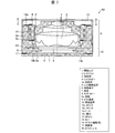
- FIG. 2 is a cross-sectional view of the camera module in the electronic apparatus of FIG.
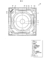
- FIG. 4 is a cross-sectional view of the camera module of FIG. 3 taken along line BB. It is sectional drawing equivalent to FIG. 3 in the camera module which concerns on 2nd Embodiment of this invention.
- FIG. 6 is a cross-sectional view of the camera module of FIG. It is sectional drawing equivalent to FIG. 3 in the camera module which concerns on 3rd Embodiment of this invention.
- FIG. 8 is a cross-sectional view of the camera module of FIG.
- FIG. 1 is a partially broken perspective view of a smartphone-type mobile phone 50 (electronic device) according to the first embodiment of the present invention.
- FIG. 1 only the casing 51 of the mobile phone 50, the vibration source represented by the vibrator 60, and the camera module 40 are shown so that the inside of the casing 51 can be seen by cutting a part of the casing 51. Above, other members having low relevance to the present invention are not shown.
- FIG. 2 is a schematic diagram for explaining a feedback control system using a displacement detection signal.
- FIG. 3 is a cross-sectional view of the camera module in the electronic apparatus of FIG. 4 is a cross-sectional view of the camera module of FIG.
- three directions orthogonal to each other are defined as an X direction, a Y direction, and a Z direction
- the Z direction is an optical axis of light incident on a camera module provided in the mobile phone 50.
- the X direction is a first direction orthogonal to the optical axis direction
- the Y direction is a second direction orthogonal to the optical axis direction and the X direction.
- the smartphone-type mobile phone 50 includes a camera module 40 and a vibration source represented by a vibrator 60 inside a casing 51 that is an outer shell.
- the camera module of the present invention includes a Hall element 41 as a displacement detection means (displacement detection unit) for detecting the displacement of the imaging lens in the optical axis direction.
- the lens position detection signal 42 detected by the hall element 41 is compared with the set position information 44 by the lens position comparison unit 43.
- the set position information 44 is position information of a target to which the imaging lens is to be moved in the autofocus operation, and is initial position information when the imaging lens is not operating when the autofocus operation is not performed. .
- a drive signal is output from the drive signal output unit 45 based on the differential signal obtained from the lens position comparison unit 43, and the drive driver 46 is operated by this drive signal to control the optical unit drive device 47. In this way, it is possible to feed back the position information signal and control it to the target position.
- position control aiming at the target position at high speed can be performed in the autofocus operation, and transient response vibration when the target position is reached can be suppressed.
- the target position is not to move from the initial position, and when the movable part tries to move due to disturbance vibration, the optical part drive device is controlled so as to suppress the movement 47 is operated. In this way, it is possible to prevent the occurrence of collision noise and chatter noise due to disturbance vibration.
- the camera module 40 includes an imaging lens 1, a lens barrel 2 that houses the imaging lens 1, and a lens holder 4 that holds the lens barrel 2 inside and is fixed by an adhesive 3.
- the camera module 40 includes a lens driving device 5 for driving the imaging lens 1 in the optical axis direction (Z direction), and an imaging element 6 having an imaging surface that performs photoelectric conversion of light passing through the imaging lens 1.
- a sensor cover 8 that covers the imaging surface of the imaging device 6 and an imaging device 10 that includes a glass substrate 9 are stacked in the optical axis direction while being placed on the substrate 7.
- the imaging lens 1 side is referred to as the upper side
- the imaging device 10 side is referred to as the lower side.
- the lens driving device 5 has an operation state in which the imaging lens 1 is driven based on an autofocus operation or a manual focus operation, and a pause state in which the imaging lens 1 is not driven.
- the lens driving device 5 moves the imaging lens 1 in the optical axis direction when in the operating state. Further, when the lens driving device 5 is in a resting state, the imaging lens 1 is disposed at the initial position. In the camera module 40 of this embodiment, when the imaging lens 1 is in the initial position, the lens holder 4 is in contact with a base 13 (fixed portion) described later.
- the lens holder 4 is configured to fix the lens barrel 2 with the adhesive 3.
- the lens holder 4 is supported movably in the Z direction with respect to the base 13 by one AF spring 12a (elastic body) on the upper side and one AF spring 12b (elastic body) on the lower side.
- the upper AF spring 12a may be fixed to the top surface of the portion where the base 13 is protruded to this height in a columnar shape, or a columnar body different from the base 13 is laminated on the base 13 to form a columnar body. You may fix to the top of the.
- the lens holder 4 has an AF coil 14 fixed to the outer periphery thereof.
- the lens holder 4 has a protrusion 4 a that is in contact with the base 13 at a mechanical end on the infinity side in the movable range in the Z direction (a reference position or an initial position on the imaging element 6 side of the movable range).
- a cover 15 is provided on the base 13 so as to surround the entire lens driving device 5, and a magnet 16 is installed on the inner wall of the cover 15 so as to face the AF coil 14.
- the cover 15 may be made of a magnetic material such as electromagnetic soft iron so as to have a function as a yoke.
- the imaging device 10 includes a substrate 7, an imaging element 6, a sensor cover 8, a glass substrate 9, and the like, and these are stacked and arranged in the optical axis direction.
- the protrusion 8a (projection 8a) on the lower side of the sensor cover 8 is disposed so as to contact the image sensor 6 as a reference surface, and is bonded to a gap generated between the sensor cover 8 and the substrate 7 due to tolerance.
- Agent 17 is filled.
- the upper AF spring 12a includes a movable side fixed end 12c fixed to the lens holder 4, a fixed side end portion 12d fixed to a fixing portion such as the base 13, and a flexible portion 12e having flexibility. ing.
- the lower AF spring 12b has the same configuration. However, the shapes need not be exactly the same.
- the AF springs 12 a and 12 b may be used as a means for energizing the AF coil 14.
- the movable side fixed end 12c is divided into two parts, and both ends of the AF coil 14 are connected to respective electrically independent parts. It ’s fine.
- a displacement detecting magnet 18 is fixed to the corner portion of the lens holder 4, and a hall element 19 is fixed to the base 13 via the FPC 20 so as to face this.
- the FPC 20 is used as a means for energizing the Hall element 19, and the other end of the FPC 20 is connected to the substrate 7 of the camera module, for example.
- the displacement detection magnet 18 and the Hall element 19 are arranged at a substantially intermediate position between the two adjacent magnets 16. This is to avoid the magnetic flux from the driving magnet 16 from entering the Hall element 19 as much as possible, and the arrangement is not limited to the one shown in the figure as long as this influence is at a level that causes no problem.
- the displacement detection magnet 18 may be installed on the base 13 side, and the Hall element 19 may be installed on the lens holder 4 side. However, in such an arrangement, wiring to the Hall element (usually 4 terminals) is required on the side of the lens holder 4 serving as a movable part, and wiring work becomes difficult.
- a part of the lens barrel 2 enters the opening 13 a of the base 13. Since it is difficult to obtain a sufficiently large flange back (distance from the lower end surface of the lens barrel 2 to the surface of the image sensor 6) of the image pickup lens 1, such a configuration is often used.
- the lens barrel 2 and the lens holder 4 are not threaded, and are fixed so that the lens barrel 2 is positioned at a predetermined position with the lens holder 4 positioned at the mechanical end on the infinity side.
- a gap of about 10 ⁇ m is formed between the lens barrel 2 and the sensor cover 8.
- the sensor cover 8 is installed on the image sensor 6 and the lens driving device 5 is mounted on the sensor cover 8.
- the position of the imaging lens 1 is desirably set to a distance from the surface of the imaging element 6 so as to be focused at the infinity side mechanical end position.
- the position of the imaging lens 1 is desirably set to a distance from the surface of the imaging element 6 so as to be focused at the infinity side mechanical end position.
- overinf This shift amount is called overinf. If the overinf is set to a large value, the stroke of the lens driving device 5 is increased by that amount, so the overinf needs to be kept to the minimum necessary. When the above various tolerances are accumulated, an overinf amount of about 25 ⁇ m is appropriate. However, since this value is affected by manufacturing tolerances and assembly tolerances of parts, it can be set to a minimum value that matches the actual situation. desirable.
- the lower reference surface of the sensor cover 8 is directly abutted against the image sensor 6, and the sensor cover 8 with increased thickness accuracy is used, and the upper surface of the sensor cover 8 is used.
- the lens barrel 2 is positioned with high accuracy because it can be said that the overinf amount is about 25 ⁇ m.
- the lens barrel 2 is attached at a position closer to the image sensor 6 side by 25 ⁇ m than the in-focus position for a subject at infinity, and in this state, there is a gap between the sensor cover 8 and the lens barrel 2. Existing.
- a vibration source represented by a vibrator 60 is disposed.
- the vibration source may be a speaker or a microphone, and may have a plurality of vibration sources.
- the vibrator 60 (vibration source) is fixed in the vicinity of the camera module 40.
- the vibration is transmitted to the camera module 40 via the housing 51.
- the movable part including the imaging lens 1 tends to move due to inertial force.
- the protruding portion of the lens holder 4 4a is in contact with the base 13 and receives contact pressure by the spring force (preload) applied by the AF spring 12a or 12b.
- the inertial force overcomes the preload and the lens holder 4 tries to lift from the base 13.
- the lens holder is lifted as it is, and when the inertial force is lost, the lens holder 4 and the base 13 come into contact again, and chatter vibrations are generated by repeating such movement.
- the displacement detecting magnet 18 and the Hall element 19 are provided as the displacement detecting means, and the displacement is always detected even when not operating as a camera module.
- the displacement of the imaging lens 1 that is not based on the driving by is detected. Therefore, when the vibrator 60 is operated and the lens holder 4 is lifted from the base 13, the displacement detection signal does not change, that is, feedback control is performed to suppress the signal change to zero, and the contact pressure Since an electric current is applied to the AF coil 14 so as to obtain a driving force in the direction of increasing, the lens holder 4 can be prevented from being lifted, and as a result, chatter noise can be prevented.
- the operation of the feedback system including the displacement detection means may be triggered by the operation signal of the vibrator 60. If the feedback system is always operated under the condition that there is no incoming call to the mobile phone 50, the power consumption increases. However, if the feedback system is also operated by using an operation command to the vibrator 60 as a trigger, the feedback system is on standby. Power consumption can be reduced.
- the displacement detection means in the optical axis direction is provided, and feedback control is possible so that the position of the movable part becomes a predetermined position. Therefore, even when the camera is not operating, the vibrator When a moving part in the camera module tries to displace due to disturbance vibration from a vibration source such as the driving force, a driving force acts in a direction to suppress the displacement, and as a result, it is not displaced by disturbance vibration, that is, no chatter noise is generated. Electronic equipment can be realized.
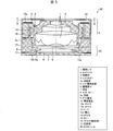
- FIG. 5 is a cross-sectional view equivalent to FIG. 3 in the camera module according to the second embodiment of the present invention.
- FIG. 6 is a cross-sectional view of the camera module of FIG.
- the second embodiment differs from the first embodiment in that the lens holder 4 and the base 13 are in contact with each other in a state where no current is applied to the AF coil 14 (resting state, the imaging lens 1 is in the initial position).
- the movable portion including the imaging lens 1, the lens barrel 2, the lens holder 4, the AF coil 14 and the like is hollowly supported by AF springs 12a and 12b (elastic body). In such a configuration, chatter that repeats contact / detachment at a minute interval does not occur.
- the projection 4a on the lower surface of the lens holder 4 may collide with the base 13 if the force becomes larger than the reaction force generated by the deformation of the spring.
- the gap between the lens holder 4 and the cover 15 is smaller than in the first embodiment, and the lens holder 4 and the cover 15 may collide.
- the second embodiment of the present invention as in the first embodiment, it is provided with a displacement detection means in the optical axis direction, and feedback control is possible so that the position of the movable part becomes a predetermined position.
- a vibration source such as a vibrator
- the driving force acts in a direction to suppress the displacement, resulting in displacement by disturbance vibrations.
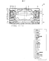
- FIG. 7 is a cross-sectional view equivalent to FIG. 3 in the camera module according to the third embodiment of the present invention.
- 8 is a cross-sectional view of the camera module of FIG.
- the third embodiment differs from the first embodiment in that a camera shake correction function is provided in addition to the autofocus function.
- the present invention can also be applied to a camera module having a camera shake correction function.
- the structure of the drive part for autofocus is almost the same as in the first embodiment.
- the magnet 16 is fixed not to the base 13 but to the intermediate holding member 21, and the protrusion 4 a of the lens holder 4 is in contact with the intermediate holding member 21 in a state where no current is applied to the AF coil 14.
- the upper AF spring 12 a and the lower AF spring 12 b are fixed to the lens holder 4 on the inner side and to the intermediate holding member 21 on the outer side.
- a portion of the upper AF spring 12a extends outward from the intermediate holding member 21, and the upper end of the suspension wire 22 is fixed to the extended portion 12f.
- the lower end of the suspension wire 22 is fixed to a substrate or the like (not shown) that is a part of the base 13.
- the number of suspension wires 22 is not particularly limited.
- the magnet for correcting camera shake (OIS magnet) is also used as the magnet 16 for autofocus.
- OIS magnet The magnet for correcting camera shake
- the magnet 16 for autofocus As shown in FIG. 8, eight OIS coils 23 are provided outside the intermediate holding member 21.
- the OIS coil 23 is for moving (swinging) the movable part in the X direction and the Y direction.
- the combination of the OIS coil 23 and the magnet 16 functions as a voice coil motor (VCM).
- VCM voice coil motor
- the OIS coil 23 only needs to be arranged at a predetermined distance from the magnet 16.
- the OIS coil 23 may be provided in a state of being fixed to the base 13 below the intermediate holding member 21. Further, the number of OIS coils 23 is not particularly limited.
- the displacement detection magnet 18 is fixed to the lens holder 4, and the Hall element 19 and the FPC 20 are fixed to the intermediate holding member 21.
- the FPC 20 is for energizing the Hall element 19, and the other end of the FPC 20 is connected to, for example, the suspension wire 22 and energized via the suspension wire 22.
- the suspension wire 22 is also used for energizing the AF coil 14, two energizing means are required for the AF coil 14 and four energizing means for the Hall element 19, and the four suspension wires 22 are insufficient. In this case, it is desirable to provide at least six suspension wires 22 in consideration of balance.
- the third embodiment is almost the same as the first embodiment with respect to the autofocus unit, and the same effect can be obtained.
- a camera module (40) is a camera module including an imaging lens (1) and a lens driving device (5) that drives the imaging lens in the optical axis direction.
- a displacement detection unit (Hall element 19) for detecting the displacement of the lens is provided, and when the displacement detection unit detects the displacement of the imaging lens that is not based on the drive by the lens drive device, the lens drive
- the apparatus is characterized in that the imaging lens is driven so as to reduce the displacement.
- the position of the imaging lens is controlled so as to reduce the displacement. Therefore, for example, even when it is affected by disturbance vibrations from a vibration source such as a vibrator or a speaker, it is possible to prevent the generation of a collision sound caused by the movable part including the imaging lens colliding with the fixed part, Generation of chatter noise due to minute changes in the contact state between the movable part and the fixed part included can be prevented.
- the camera module according to aspect 2 of the present invention is the camera module according to aspect 1, wherein the lens driving device includes a lens holder (4) that holds the imaging lens, and a fixed portion (base 13) that is not displaced when the imaging lens is driven.
- the lens driving device has an operation state for driving the imaging lens and a resting state in which the imaging lens is not driven. In the resting state, the lens holder and the fixing portion May be in contact with each other.
- the position of the imaging lens is controlled so as to reduce the displacement, so that the lens holder and the fixed part are in contact with each other. Further, chatter noise generated by minute changes in the contact state between the lens holder and the fixed portion can be suppressed.
- the camera module according to Aspect 3 of the present invention is the camera module according to Aspect 1, wherein the lens driving device includes a lens holder (4) that holds the imaging lens, and a fixed portion that is not displaced when the imaging lens is driven (base 13), and the lens driving device has an operation state of driving the imaging lens and a resting state of not driving the imaging lens, and the lens holder is an elastic body (AF springs 12a and 12b).
- the lens holder and the fixing portion may be held so as not to contact each other in the resting state.
- the lens holder and the fixing portion are held so as not to contact each other, even when the camera module is affected by disturbance vibration in the resting state, the lens holder and the fixing portion are fixed. It is possible to prevent chatter noise from occurring between the two parts.
- the position of the imaging lens is controlled so as to reduce the displacement. In this state, it is possible to suppress a collision sound generated by the collision between the lens holder and the fixed portion.
- the electronic device (mobile phone 50) according to aspect 4 of the present invention may have a configuration in which any one of the camera modules according to aspects 1 to 3 is mounted.
- the electronic device has the vibration source (vibrator 60) that operates electrically in the aspect 4, and operates the displacement detection unit when the operation of the vibration source is detected. It may be a configuration.
- the displacement detection unit can be operated when detecting the operation of a vibration source such as a vibrator or a speaker mounted in an electronic device, and can be prepared for the occurrence of a collision sound or chatter noise.
- the power consumption can be reduced compared to the case where the detection unit is operated.
- an example of a mobile phone has been described.
- an electronic device including a camera module in the present invention is not limited to a mobile phone.
- Examples of the electronic device include a portable game machine and a digital camera.
- the present invention can also be expressed as follows.
- the camera module of the present invention includes an imaging element that converts an optical signal into an electrical signal, an imaging lens that causes light to enter the imaging element, and a lens that drives the imaging lens in the optical axis direction for an autofocus operation.
- a camera module including a driving device, the lens driving device including a displacement detection means for detecting the displacement of the imaging lens, and the displacement detection means even when the autofocus operation is not performed.
- the displacement detecting means detects a movement signal
- the lens driving device can be operated so as to prevent the movement.
- the lens driving device has a lens holder that holds the imaging lens and a fixing portion that is not displaced when the imaging lens is driven, and the lens driving device is not applied with a signal for moving the lens holder.
- fixed part are contacting may be sufficient.
- the lens driving device includes a lens holder that holds the imaging lens and a fixing portion that does not displace when the imaging lens is driven, and the lens holder is supported by an elastic body to move the lens holder.
- the lens holder and the fixed portion may be held so as not to contact each other in a state where the signal is not applied.
- the electronic device of the present invention is characterized by mounting the above camera module.
- the electronic device may have a vibration source that operates electrically, and the displacement detection unit may be operated when the operation of the vibration source is detected.
- the present invention can be used for a camera module having an autofocus function and an electronic device such as a mobile phone equipped with the camera module.
Landscapes
- Physics & Mathematics (AREA)
- General Physics & Mathematics (AREA)
- Optics & Photonics (AREA)
- Engineering & Computer Science (AREA)
- Multimedia (AREA)
- Signal Processing (AREA)
- Studio Devices (AREA)
- Lens Barrels (AREA)
- Camera Bodies And Camera Details Or Accessories (AREA)
Abstract
Description
本発明に係るカメラモジュールおよび電子機器の一実施形態(第1実施形態)について、図1~図4を参照しつつ説明する。図1は、本発明の第1実施形態に係るスマートフォン型の携帯電話50(電子機器)の部分破断斜視図である。なお、図1では、携帯電話50の筐体51、バイブレーター60で代表される振動源、およびカメラモジュール40のみを、筐体51の一部を切断して筐体51内が見えるように示した上で、本発明との関連性が低い他の部材は示していない。図2は、変位検出信号を利用したフィードバック制御系を説明するための概略図である。図3は、図1の電子機器の中のカメラモジュールのA-A矢視断面図である。図4は、図3のカメラモジュールのB-B矢視断面図である。
図2を用いてフィードバック制御について説明する。カメラモジュールの詳細構造については後述するが、本発明のカメラモジュールは、撮像レンズの光軸方向の変位を検出するための変位検出手段(変位検出部)としてのホール素子41を備えている。ホール素子41により検出されたレンズ位置検出信号42は、レンズ位置比較部43で設定位置情報44と比較される。ここで、設定位置情報44は、オートフォーカス動作においては、撮像レンズを移動させたい目標の位置情報となり、オートフォーカス動作していないときは、撮像レンズが動作していない時の初期位置情報となる。レンズ位置比較部43から得られる差動信号に基づいて駆動信号出力部45で駆動信号が出力され、この駆動信号によって駆動ドライバー46が動作されて光学部駆動装置47が制御される。このように、位置情報信号をフィードバックして、目標位置に制御することが可能となっている。
カメラモジュール40の詳細について、図3および図4を用いて説明する。カメラモジュール40は、撮像レンズ1、撮像レンズ1を収納するレンズバレル2、およびレンズバレル2を内部に保持するとともに接着剤3によって固定されているレンズホルダー4を有している。そして、カメラモジュール40は、撮像レンズ1を光軸方向(Z方向)に駆動するためのレンズ駆動装置5と、撮像レンズ1を経由した光の光電変換を行う、撮像面を有する撮像素子6を基板7上に載置するとともに、撮像素子6の撮像面をカバーするセンサーカバー8およびガラス基板9を備えた撮像装置10とが光軸方向に積層されている。以下の説明では、便宜上、撮像レンズ1側を上方、撮像装置10側を下方とする。
次に、カメラモジュール40を携帯電話50に実装固定(搭載)した場合について説明する。カメラモジュール40の近傍には、バイブレーター60で代表される振動源が配置されている。振動源は、スピーカーやマイクロフォンである可能性もあり、複数の振動源を保有する場合もある。
以上のように、本実施形態では、光軸方向の変位検出手段を備えており、可動部の位置が所定の位置になるようフィードバック制御が可能なため、カメラとしての非動作時においても、バイブレーター等の振動源からの外乱振動を受けて、カメラモジュール内の可動部が変位しようとすると、その変位を抑える方向に駆動力が作用し、結果として外乱振動によって変位しない、すなわちビビリ音が生じない電子機器が実現できる。
本発明の第2実施形態に係るカメラモジュールについて、図5および図6を用いて説明する。図5は、本発明の第2実施形態に係るカメラモジュールにおける、図3と同等の断面図である。図6は、図5のカメラモジュールのC-C矢視断面図である。
本発明の第3実施形態に係るカメラモジュールについて、図7および図8を用いて説明する。図7は、本発明の第3実施形態に係るカメラモジュールにおける、図3と同等の断面図である。図8は、図7のカメラモジュールのD-D矢視断面図である。
本発明の態様1に係るカメラモジュール(40)は、撮像レンズ(1)と、該撮像レンズを光軸方向に駆動するレンズ駆動装置(5)と、を備えたカメラモジュールであって、該撮像レンズの変位を検出するための変位検出部(ホール素子19)を備えており、該変位検出部が、該レンズ駆動装置による駆動に基づかない該撮像レンズの変位を検出した場合に、該レンズ駆動装置は、該変位を低減するように該撮像レンズを駆動することを特徴とする。
なお、第1実施形態では携帯電話における例を説明しているが、本発明における、カメラモジュールを備えた電子機器は携帯電話に限定されない。電子機器としては、携帯ゲーム機、デジタルカメラ等が挙げられる。
2 レンズバレル
3 接着剤
4 レンズホルダー
4a 突起部
5 レンズ駆動装置
6 撮像素子
7 基板
8 センサーカバー
8a 突起部
9 ガラス基板
10 撮像装置
12a AFバネ
12b AFバネ
13 ベース
14 AFコイル
15 カバー
16 マグネット(駆動用)
17 接着剤
18 マグネット(変位検出用)
19 ホール素子
20 FPC
21 中間保持部材
22 サスペンションワイヤー
23 OISコイル
40 カメラモジュール
50 携帯電話
51 筐体
60 バイブレーター(振動源)
Claims (5)
- 撮像レンズと、
該撮像レンズを光軸方向に駆動するレンズ駆動装置と、を備えたカメラモジュールであって、
該撮像レンズの変位を検出するための変位検出部を備えており、
該変位検出部が、該レンズ駆動装置による駆動に基づかない該撮像レンズの変位を検出した場合に、該レンズ駆動装置は、該変位を低減するように該撮像レンズを駆動することを特徴とするカメラモジュール。 - 上記レンズ駆動装置は、上記撮像レンズを保持するレンズホルダーと、該撮像レンズを駆動するときに変位しない固定部とを有し、
上記レンズ駆動装置は、上記撮像レンズを駆動する動作状態と、上記撮像レンズを駆動しない休止状態とを有しており、
該休止状態において、該レンズホルダーと該固定部とは、互いに接触していることを特徴とする請求項1に記載のカメラモジュール。 - 上記レンズ駆動装置は、上記撮像レンズを保持するレンズホルダーと、該撮像レンズを駆動するときに変位しない固定部とを有し、
上記レンズ駆動装置は、上記撮像レンズを駆動する動作状態と、上記撮像レンズを駆動しない休止状態とを有しており、
該レンズホルダーは弾性体により支持されており、該休止状態において、該レンズホルダーと該固定部とは、互いに接触しないように保持されていることを特徴とする請求項1に記載のカメラモジュール。 - 請求項1~3の何れか1項に記載のカメラモジュールを搭載したことを特徴とする電子機器。
- 電気的に動作する振動源を保有しており、
上記振動源の動作を検出したときに上記変位検出部を動作させることを特徴とする請求項4に記載の電子機器。
Priority Applications (3)
| Application Number | Priority Date | Filing Date | Title |
|---|---|---|---|
| US15/309,299 US10031401B2 (en) | 2014-05-19 | 2015-03-17 | Camera module and electronic device |
| JP2016520974A JP6271721B2 (ja) | 2014-05-19 | 2015-03-17 | カメラモジュール及び電子機器 |
| CN201580024854.6A CN106461910B (zh) | 2014-05-19 | 2015-03-17 | 相机模块及电子设备 |
Applications Claiming Priority (2)
| Application Number | Priority Date | Filing Date | Title |
|---|---|---|---|
| JP2014103767 | 2014-05-19 | ||
| JP2014-103767 | 2014-05-19 |
Publications (1)
| Publication Number | Publication Date |
|---|---|
| WO2015178083A1 true WO2015178083A1 (ja) | 2015-11-26 |
Family
ID=54553760
Family Applications (1)
| Application Number | Title | Priority Date | Filing Date |
|---|---|---|---|
| PCT/JP2015/057952 Ceased WO2015178083A1 (ja) | 2014-05-19 | 2015-03-17 | カメラモジュール及び電子機器 |
Country Status (4)
| Country | Link |
|---|---|
| US (1) | US10031401B2 (ja) |
| JP (1) | JP6271721B2 (ja) |
| CN (1) | CN106461910B (ja) |
| WO (1) | WO2015178083A1 (ja) |
Cited By (7)
| Publication number | Priority date | Publication date | Assignee | Title |
|---|---|---|---|---|
| CN106060375A (zh) * | 2015-04-08 | 2016-10-26 | 三星电机株式会社 | 数字拍摄设备和控制方法 |
| WO2017175505A1 (ja) * | 2016-04-08 | 2017-10-12 | アルプス電気株式会社 | レンズ駆動装置 |
| KR20180003284A (ko) * | 2016-06-30 | 2018-01-09 | 엘지이노텍 주식회사 | 렌즈 구동 장치, 카메라 모듈 및 광학기기 |
| CN112130400A (zh) * | 2019-06-25 | 2020-12-25 | 大阳科技股份有限公司 | 成像镜头模块与电子装置 |
| JP2021063971A (ja) * | 2019-10-11 | 2021-04-22 | 日本電産サンキョー株式会社 | 振れ補正機能付き光学ユニット |
| US12078866B2 (en) | 2016-05-09 | 2024-09-03 | Lg Innotek Co., Ltd. | Lens driving device, camera module, and optical device |
| US12395739B2 (en) | 2021-12-17 | 2025-08-19 | Rohm Co., Ltd. | Actuator driver, camera module using thereof, and electronic device |
Families Citing this family (3)
| Publication number | Priority date | Publication date | Assignee | Title |
|---|---|---|---|---|
| US10334170B2 (en) * | 2015-01-23 | 2019-06-25 | Samsung Electro-Mechanics Co., Ltd. | Camera module |
| WO2016200126A1 (ko) | 2015-06-08 | 2016-12-15 | 엘지이노텍(주) | 카메라 모듈 |
| CN111130304B (zh) * | 2020-01-21 | 2025-11-11 | 新思考电机有限公司 | 一种五轴ois结构的音圈马达、照相装置及电子设备 |
Citations (5)
| Publication number | Priority date | Publication date | Assignee | Title |
|---|---|---|---|---|
| JP2006337763A (ja) * | 2005-06-02 | 2006-12-14 | Sharp Corp | レンズ保持手段 |
| WO2008029944A1 (en) * | 2006-09-08 | 2008-03-13 | Sharp Kabushiki Kaisha | Imaging device and method of producing the same |
| JP2009115895A (ja) * | 2007-11-02 | 2009-05-28 | Alps Electric Co Ltd | カメラモジュール |
| JP2009182680A (ja) * | 2008-01-30 | 2009-08-13 | Kyocera Corp | 携帯電子機器及びその制御方法 |
| JP2011055564A (ja) * | 2009-08-31 | 2011-03-17 | Nidec Sankyo Corp | 直線駆動装置および光学素子駆動装置 |
Family Cites Families (11)
| Publication number | Priority date | Publication date | Assignee | Title |
|---|---|---|---|---|
| JPS61267974A (ja) * | 1985-05-22 | 1986-11-27 | Oki Electric Ind Co Ltd | キヤリツジ駆動装置 |
| JPH05281449A (ja) | 1992-03-31 | 1993-10-29 | Sony Corp | 焦点調節装置 |
| JP2006106070A (ja) * | 2004-09-30 | 2006-04-20 | Olympus Corp | 鏡枠 |
| US7623774B2 (en) * | 2006-08-01 | 2009-11-24 | Motorola, Inc. | Devices and methods for determining orientation of a camera |
| JP2008040017A (ja) | 2006-08-03 | 2008-02-21 | Nidec Sankyo Corp | レンズ駆動装置 |
| JP4986551B2 (ja) | 2006-09-06 | 2012-07-25 | 三洋電機株式会社 | レンズ駆動制御装置 |
| JP5767786B2 (ja) | 2009-06-18 | 2015-08-19 | セミコンダクター・コンポーネンツ・インダストリーズ・リミテッド・ライアビリティ・カンパニー | フォーカス制御回路 |
| CN101930150B (zh) | 2009-06-18 | 2012-01-04 | 三洋电机株式会社 | 聚焦控制电路 |
| US20130169832A1 (en) * | 2011-12-29 | 2013-07-04 | Lg Innotek Co., Ltd. | Camera module and auto focusing method of camera module |
| JP5955609B2 (ja) | 2012-03-30 | 2016-07-20 | 日本電産サンキョー株式会社 | レンズ駆動装置 |
| TWI516855B (zh) * | 2014-05-15 | 2016-01-11 | 台灣東電化股份有限公司 | 三軸閉迴路防手震結構 |
-
2015
- 2015-03-17 US US15/309,299 patent/US10031401B2/en not_active Expired - Fee Related
- 2015-03-17 CN CN201580024854.6A patent/CN106461910B/zh not_active Expired - Fee Related
- 2015-03-17 JP JP2016520974A patent/JP6271721B2/ja not_active Expired - Fee Related
- 2015-03-17 WO PCT/JP2015/057952 patent/WO2015178083A1/ja not_active Ceased
Patent Citations (5)
| Publication number | Priority date | Publication date | Assignee | Title |
|---|---|---|---|---|
| JP2006337763A (ja) * | 2005-06-02 | 2006-12-14 | Sharp Corp | レンズ保持手段 |
| WO2008029944A1 (en) * | 2006-09-08 | 2008-03-13 | Sharp Kabushiki Kaisha | Imaging device and method of producing the same |
| JP2009115895A (ja) * | 2007-11-02 | 2009-05-28 | Alps Electric Co Ltd | カメラモジュール |
| JP2009182680A (ja) * | 2008-01-30 | 2009-08-13 | Kyocera Corp | 携帯電子機器及びその制御方法 |
| JP2011055564A (ja) * | 2009-08-31 | 2011-03-17 | Nidec Sankyo Corp | 直線駆動装置および光学素子駆動装置 |
Cited By (11)
| Publication number | Priority date | Publication date | Assignee | Title |
|---|---|---|---|---|
| CN106060375A (zh) * | 2015-04-08 | 2016-10-26 | 三星电机株式会社 | 数字拍摄设备和控制方法 |
| US10432865B2 (en) | 2015-04-08 | 2019-10-01 | Samsung Electro-Mechanics Co., Ltd. | Digital photographing apparatus and control method |
| WO2017175505A1 (ja) * | 2016-04-08 | 2017-10-12 | アルプス電気株式会社 | レンズ駆動装置 |
| US12078866B2 (en) | 2016-05-09 | 2024-09-03 | Lg Innotek Co., Ltd. | Lens driving device, camera module, and optical device |
| KR20180003284A (ko) * | 2016-06-30 | 2018-01-09 | 엘지이노텍 주식회사 | 렌즈 구동 장치, 카메라 모듈 및 광학기기 |
| KR102812493B1 (ko) * | 2016-06-30 | 2025-05-27 | 엘지이노텍 주식회사 | 렌즈 구동 장치, 카메라 모듈 및 광학기기 |
| CN112130400A (zh) * | 2019-06-25 | 2020-12-25 | 大阳科技股份有限公司 | 成像镜头模块与电子装置 |
| CN112130400B (zh) * | 2019-06-25 | 2021-11-23 | 大阳科技股份有限公司 | 成像镜头模块与电子装置 |
| JP2021063971A (ja) * | 2019-10-11 | 2021-04-22 | 日本電産サンキョー株式会社 | 振れ補正機能付き光学ユニット |
| JP7344780B2 (ja) | 2019-10-11 | 2023-09-14 | ニデックインスツルメンツ株式会社 | 振れ補正機能付き光学ユニット |
| US12395739B2 (en) | 2021-12-17 | 2025-08-19 | Rohm Co., Ltd. | Actuator driver, camera module using thereof, and electronic device |
Also Published As
| Publication number | Publication date |
|---|---|
| JPWO2015178083A1 (ja) | 2017-04-20 |
| JP6271721B2 (ja) | 2018-01-31 |
| CN106461910A (zh) | 2017-02-22 |
| CN106461910B (zh) | 2019-05-28 |
| US10031401B2 (en) | 2018-07-24 |
| US20170219914A1 (en) | 2017-08-03 |
Similar Documents
| Publication | Publication Date | Title |
|---|---|---|
| JP6271721B2 (ja) | カメラモジュール及び電子機器 | |
| US11880126B2 (en) | Lens driving device, and camera module and optical device, which include same | |
| CN109975942B (zh) | 透镜驱动装置、摄像机模块及摄像机搭载装置 | |
| JP5405622B2 (ja) | カメラモジュール | |
| JP6199398B2 (ja) | カメラモジュール | |
| KR101184812B1 (ko) | 손떨림 보정용 서스펜션 와이어 및 이를 포함하는 영상 촬상 장치 | |
| JP5329629B2 (ja) | カメラモジュール | |
| JP6414396B2 (ja) | レンズホルダ駆動装置およびカメラ付き携帯端末 | |
| JP6250597B2 (ja) | 電磁駆動モジュールおよびそれを用いたレンズ装置 | |
| JP6129513B2 (ja) | 手振れ補正機能付きカメラモジュールおよびこれを搭載した電子機器 | |
| JP5512783B2 (ja) | カメラモジュール | |
| US10935752B2 (en) | Lens driving device, and camera module and optical device, which include same | |
| CN112114467A (zh) | 透镜驱动装置、摄影机模块及光学设备 | |
| CN105607383A (zh) | 透镜移动装置 | |
| CN107526232B (zh) | 镜头驱动装置 | |
| JP2023109669A (ja) | レンズ駆動装置 | |
| CN218099885U (zh) | 用于相机的致动器和相机模块 | |
| JP2019008329A (ja) | レンズホルダ駆動装置およびカメラ付き携帯端末 | |
| JP5985259B2 (ja) | 手振れ補正機能付きカメラモジュールを搭載した電子機器 | |
| JP2018173580A (ja) | レンズ駆動装置 | |
| JP2014089265A (ja) | カメラモジュールの組み立て方法およびカメラモジュール | |
| TWI440948B (zh) | 相機模組 | |
| JP6533821B2 (ja) | レンズ駆動装置 |
Legal Events
| Date | Code | Title | Description |
|---|---|---|---|
| 121 | Ep: the epo has been informed by wipo that ep was designated in this application |
Ref document number: 15796928 Country of ref document: EP Kind code of ref document: A1 |
|
| ENP | Entry into the national phase |
Ref document number: 2016520974 Country of ref document: JP Kind code of ref document: A |
|
| WWE | Wipo information: entry into national phase |
Ref document number: 15309299 Country of ref document: US |
|
| NENP | Non-entry into the national phase |
Ref country code: DE |
|
| 122 | Ep: pct application non-entry in european phase |
Ref document number: 15796928 Country of ref document: EP Kind code of ref document: A1 |