WO2015174237A1 - チャイルドシート - Google Patents
チャイルドシート Download PDFInfo
- Publication number
- WO2015174237A1 WO2015174237A1 PCT/JP2015/062343 JP2015062343W WO2015174237A1 WO 2015174237 A1 WO2015174237 A1 WO 2015174237A1 JP 2015062343 W JP2015062343 W JP 2015062343W WO 2015174237 A1 WO2015174237 A1 WO 2015174237A1
- Authority
- WO
- WIPO (PCT)
- Prior art keywords
- seat
- lock
- child seat
- rotation
- operation means
- Prior art date
Links
Images


Classifications
-
- B—PERFORMING OPERATIONS; TRANSPORTING
- B60—VEHICLES IN GENERAL
- B60N—SEATS SPECIALLY ADAPTED FOR VEHICLES; VEHICLE PASSENGER ACCOMMODATION NOT OTHERWISE PROVIDED FOR
- B60N2/00—Seats specially adapted for vehicles; Arrangement or mounting of seats in vehicles
- B60N2/24—Seats specially adapted for vehicles; Arrangement or mounting of seats in vehicles for particular purposes or particular vehicles
- B60N2/26—Seats specially adapted for vehicles; Arrangement or mounting of seats in vehicles for particular purposes or particular vehicles for children
- B60N2/28—Seats readily mountable on, and dismountable from, existing seats or other parts of the vehicle
- B60N2/2821—Seats readily mountable on, and dismountable from, existing seats or other parts of the vehicle having a seat and a base part
-
- A—HUMAN NECESSITIES
- A47—FURNITURE; DOMESTIC ARTICLES OR APPLIANCES; COFFEE MILLS; SPICE MILLS; SUCTION CLEANERS IN GENERAL
- A47C—CHAIRS; SOFAS; BEDS
- A47C3/00—Chairs characterised by structural features; Chairs or stools with rotatable or vertically-adjustable seats
- A47C3/18—Chairs or stools with rotatable seat
-
- B—PERFORMING OPERATIONS; TRANSPORTING
- B60—VEHICLES IN GENERAL
- B60N—SEATS SPECIALLY ADAPTED FOR VEHICLES; VEHICLE PASSENGER ACCOMMODATION NOT OTHERWISE PROVIDED FOR
- B60N2/00—Seats specially adapted for vehicles; Arrangement or mounting of seats in vehicles
- B60N2/24—Seats specially adapted for vehicles; Arrangement or mounting of seats in vehicles for particular purposes or particular vehicles
- B60N2/26—Seats specially adapted for vehicles; Arrangement or mounting of seats in vehicles for particular purposes or particular vehicles for children
- B60N2/28—Seats readily mountable on, and dismountable from, existing seats or other parts of the vehicle
- B60N2/2869—Seats readily mountable on, and dismountable from, existing seats or other parts of the vehicle rotatable about a vertical axis
Definitions
- the present invention relates to a child seat, and more particularly to a child seat provided with a rotation mechanism for rotating a seating seat with respect to a mounting base attached to a vehicle.
- the former is a child seat having a configuration as disclosed in Patent Document 1, for example.
- the operation means can always be operated from the same direction regardless of the direction in which the seating seat faces the traveling direction of the vehicle.
- a child seat having a structure disclosed in Patent Documents 2 and 3 is known.
- the child seat disclosed in Patent Document 2 is provided with operation means on the lower side of the seating portion of the seat.
- the child seat disclosed in Patent Document 3 is provided with operation means behind the backrest portion of the seat.
- the child seat provided with the operation means on the pedestal side and the child seat provided with the operation means on the seating seat side each have advantages specific to the configuration.
- the child seat of each configuration has a problem of special configuration.
- the rotation lock in the child seat provided with the rotation mechanism, the rotation lock can be released and the rotation operation can be performed with one hand, and the operation means can be easily operated regardless of the direction of the seating seat.
- the object is to provide a child seat that will be in position.
- a child seat includes a mounting base with a rotating base having a rotating path and a recess formed in at least a part of the rotating path, and a movement along the rotating path. And a lock portion disposed so as to be able to fit into the concave portion, biasing means for biasing the lock portion toward the surface on which the concave portion is formed, and the lock portion connected to the lock portion.
- a plurality of operation means having a lock release part for releasing the fitting between the lock part and the recessed part by moving to a side opposite to the urging direction by the urging means, and configured to be rotatable with respect to the rotation base; And a seat seat with an attached rotating plate.
- the concave portion is provided at a position corresponding to the front side of the mounting base on the circuit path, and the plurality of operation means are at least on the front side of the seating seat. It is good to provide in the position corresponding to the corresponding position and the back side.
- the operation means is always located on the front side of the mounting base in a state where the rotation operation of the seating seat is locked.
- a plurality of the recesses are provided radially from the rotation center of the rotating plate, and an arrangement angle between the plurality of recesses from the rotation center is set as the rotation center. It is desirable to make it smaller than the arrangement angle of the operation means as the base point.
- the rotation of the seating seat can be locked at an arbitrary position. Further, there is no possibility that the rotation is locked by another operation means while the rotation lock is released by one operation means.
- the operating means can be present at a position where it can be easily operated.
- FIG. 3 is a diagram showing a configuration of an AA cross section in FIG. 2.
- FIG. 3 is a diagram showing a configuration of a BB cross section in FIG. 2.
- FIG. 4 is a diagram illustrating a configuration of a CC cross section in FIG. 3.
- It is a figure which shows the planar structure of an attachment base.
- It is a figure which shows the planar structure of a rotating plate.
- It is a figure which shows the structure of the D direction arrow in FIG.
- FIG. 15 is a schematic diagram illustrating a configuration of a FF cross section in FIG. 14. It is sectional drawing which shows the characteristic structure of the 6th application form in the child seat which concerns on embodiment.
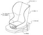
- the child seat 10 according to the present embodiment is mainly composed of a mounting base 12 and a seating seat 22.
- FIG. 1 is a perspective view showing the configuration of the front, plane, and right side of the child seat according to the embodiment
- FIG. 2 is a diagram showing the configuration of the right side of the child seat according to the embodiment.
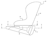
- 3 shows a cross section taken along the line AA in FIG. 2
- FIG. 4 shows a cross section taken along the line BB in FIG.
- FIG. 5 shows a CC cross section in FIG. *
- the mounting base 12 is a member fixed to a vehicle seat (not shown), and includes a base (referred to as a rotating base 14) in a rotating mechanism for rotating the seating seat 22. ing.
- FIG. 6 shows a plan view of the mounting base 12 (angle based on the state of FIG. 2). *
- the rotation base 14 is configured based on a support surface 16, a circulation path 18, and a recess 20.
- the support surface 16 is a surface that supports the weight of the seating sheet 22 including a rotating plate 26 (see FIG. 5), which will be described in detail later.
- the planar shape is substantially circular.
- a bearing hole 16 a is formed for allowing the rotary shaft 30 provided in the rotary plate 26 to pass therethrough.
- the circling path 18 is a path for circling a lock portion 34 (see FIG. 5) that projects to the lower side of the rotating plate 26, which will be described in detail later.
- the circulation path 18 is provided along the outer peripheral shape of the support surface 16.
- the circular path 18 is formed to be a concave groove with respect to the support surface 16 because the lock portion 34 protruding from the rotating plate 26 mounted on the support surface 16 is disposed.
- the circulation path 18 is comprised by three wall surfaces, such as the inner peripheral side wall surface 18a, the outer peripheral side wall surface 18b, and the bottom face 18c.
- the recess 20 is provided in the circulation path 18. Specifically, it is formed on the inner peripheral side wall surface 18 a among the wall surfaces constituting the circulation path 18. Further, the recess 20 is provided at a position (front side) corresponding to the front surface of the mounting base 12 in the rotation base 14. Further, in the present embodiment, as can be seen from FIG. 6, a support that is a part of the inner peripheral side wall surface 18 a and that corresponds to the side surface of the mounting base 12 has a substantially circular shape separately from the recess 20 described above. The surface 16 is provided with a cutout portion 16b that is partially cut out in a straight line shape in a plan view. *
- the lock portion 34 provided in the rotary plate 26, which will be described in detail later, is urged against the inner peripheral side wall surface 18 a forming the recess 20. For this reason, when the lock part 34 which moves the circumference path
- the seating seat 22 includes a seat body 24 having a backrest portion 24 a and a seating portion 24 b, and a rotating plate 26 provided below the seating portion 24 b constituting the seat body 24.
- FIG. 7 shows a plan view of the rotating plate
- FIGS. 8 and 9 show configurations of the D direction arrow and the E direction arrow in FIG. 7, respectively.
- the seat body 24 is a seat on which a child who uses the child seat 10 is seated.
- the rotary plate 26 includes a plate main body 28, a rotary shaft 30, and an operation means 32.
- the plate main body 28 has one surface that contacts and slides on the support surface of the rotary base 14 described above, and supports the sheet main body 24 by the other surface.
- a rotating shaft 30 is projected from one surface side of the plate body 28.
- the rotating shaft 30 is inserted into a bearing hole 16 a formed in the support surface 16 of the rotating base 14.
- a stopper 30 a that is engaged with the bearing hole 16 a is provided at the tip of the rotating shaft 30.
- the retaining structure of the rotating shaft 30 with respect to the bearing hole 16a is not limited to the present embodiment, and other existing retaining structures can be used.
- the plate body 28 is provided with an opening 28a (see FIG. 5) on the plate surface for arranging an operation means 32 to be described later in detail. *
- the operation means 32 includes a lock part 34 and a lock release part 36 connected to the lock part 34.
- the operation means 32 is disposed on the other surface of the plate main body 28, but the lock portion 34 is disposed so as to protrude to one surface side of the plate main body 28 through the opening 28a. .
- the lock part 34 and the lock release part 36 are respectively disposed on one surface and the other surface via the plate body 28.
- the plate main body 28 is formed in a circular shape, and the opening 28 a provided in the plate main body 28 can move the operating means 32 in the radial direction in a state where the lock portion 34 is arranged. Is formed.
- the movement width of the operating means 32 is such that at least the lock portion 34 is fitted into the recess 20 formed in the rotary base 14, the fitting of the lock portion 34 and the recess 20 is released, and the lock portion 34 is turned around.
- the range of the position arranged at 18 may be sufficient.
- the operating means 32 is urged toward the center of the plate body 28 by an urging means (not shown). For this reason, the lock part 34 will be in the state urged
- the lock portion 34 may be a protrusion that can be fitted into the recess 20.
- the unlocking portion 36 resists the urging force and needs to pull out the locking portion 34 from the recess 20.
- the unlocking part 36 is formed with a handle for placing a finger.
- At least two operation means 32 are arranged with respect to the plate body 28.
- the seat body 24 when the seat body 24 is mounted on the rotating plate 26, it is preferable to arrange the seat body 24 at a position on the front side of the seating portion 24b and a position on the backrest portion 24a side of the seating portion 24. Even if the front part of the seating part 24b faces the front of the mounting base 12 or the backrest part 24a is located in front of the mounting base 12, the operation can be performed.
- the means 32 is positioned in front of the mounting base 12, and the operability can be kept good.
- the lock portion 34 of the operating means 32 positioned on the front side of the mounting base 12 is used. Is fitted in a recess 20 provided in the rotary base 14. Therefore, by pulling the lock release portion 36 of the operating means 32 located on the front side of the mounting base 12 to the front side, the lock portion 34 and the recess 20 are disengaged, and the lock relating to the rotation operation is released. The By applying a force in the direction in which the seating seat 22 is rotated in the unlocked state, the seating seat 22 is rotated with the rotation shaft 30 as a base point.
- the lock portion 34 which has been disengaged from the recess 20, slides along the inner peripheral side wall surface 18 a of the circulation path 18 as the seating seat 22 rotates.
- the lock portion 34 reaches the notch portion 16b formed in the inner peripheral side wall surface 18a of the circulation path 18 and is temporarily locked.
- the temporary lock state is released, and the lock portion 34 slides along the inner peripheral side wall surface 18a of the circulation path 18 again.
- the operating means 32 disposed on the backrest portion 24 a side When the seating seat 22 is rotated about 180 degrees, the operating means 32 disposed on the backrest portion 24 a side is positioned in front of the mounting base 12. For this reason, the lock part 34 in the operating means 32 on the backrest part 24a side fits into the recess 20 and locks the rotation of the seating seat 22.
- the operation means 32 that functions to lock the rotation of the seating seat 22 is always located on the front side of the mounting base 12 when the rotation of the seating seat 22 is locked. It becomes. For this reason, the operability at the time of unlocking is always good.
- the arrangement position of the recessed part 20 was made into the position which becomes the front side of the mounting base 12, the arrangement position of the recessed part 20 is not restricted to this. That is, what is necessary is just to set it according to the operativity of the operation means 32, and the direction which wants to fix the seating sheet 22.
- FIG. The arrangement range of the recesses 20 is desirably a range of ⁇ 90 degrees around the center of rotation with the front side of the mounting base 12 as a base point. *
- the number of operation means 32 is four.
- the arrangement angle between the operation means 32 is preferably about 90 degrees.
- the lock is applied every time the seating seat 22 is rotated about 90 degrees.
- the operating means 32 that always contributes to unlocking is positioned in front of the mounting base 12. Further, the unlocking operation and the operation of rotating the seating seat 22 can be performed simultaneously with one hand.
- the support surface 16 is provided with the notch 16b having a straight line shape in plan view at a position about 90 degrees from the position where the recess 20 is formed, and the temporary lock is applied when the seating seat 22 is rotated. It was stated that it would occur. However, in this application form, since it is set as the structure which locks about every 90 degree
- the number of the recesses 20 is two.
- the arrangement angle is set to be smaller than the arrangement angle of the operation means 32.
- the arrangement angle of the two operation means 32 is about 180 degrees, and the arrangement angle of the two recesses 20 is about 90 degrees (both are based on the center of the support surface 16).
- the arrangement position of the recessed part 20 it is desirable to arrange
- the arrangement position of the recess 20 is a position where the operation means 32 is locked or unlocked. For this reason, the operation means 32 for performing the unlocking operation is provided on the front side or the side surface side of the mounting base 12 by providing the recess 20 in a range of ⁇ 90 degrees with the position on the front side of the mounting base 12 as a base point. Therefore, there is no possibility of impairing operability. *
- the number of recesses 20 and the number of operation means 32 are both three.
- the angle ⁇ 1 between the two recesses 20 at the most distant positions is the arrangement angle of the two operation means 32 arranged adjacent to each other. It is desirable to arrange so as to be smaller than ⁇ 2. While the locking operation with the concave portion 20 is released by one operation means 32 and the seating seat 22 is being rotated, the other operation means 32 is fitted into the recess 20 and the rotation of the seating seat 22 is locked. This is to avoid such a situation. *
- the arrangement angles of the adjacent recesses 20 are each about 30 degrees, and the arrangement angles of the adjacent operation means 32 are each about 120 degrees. Even in such an application mode, it is possible to exhibit the same effect as the second application mode described above. *
- the lock portion 34 constituting the operation means 32 is configured to be urged toward the inner peripheral side wall surface 18 a among the wall surfaces constituting the circulation path 18.
- the lock portion 34 is set as the structure which urges
- the operating means 32 is provided with a biasing means (not shown) so that a biasing force directed in a direction away from the rotation center of the rotating plate 26 (see FIG. 7) acts.
- FIG. 14 is a schematic diagram illustrating a planar configuration of the rotation mechanism
- FIG. 15 is a schematic diagram illustrating a cross section taken along line FF in FIG.
- the concave portion 20 is formed on the bottom surface 18 c of the wall surfaces constituting the circulation path 18.
- the locking portion 34 of the operating means 32 that slides along the circular path 18 formed in a groove shape falls into the recess 20, so that the rotation of the seating seat 22 is locked.
- FIG. 16 is a view showing a cross-sectional configuration (corresponding to the CC cross section in FIG. 3) in the child seat 10 according to this application form.
- the seating seat 22 and the mounting base 12 are Shown in a disassembled state. *
- the lock portion 34 of the operation means 32 is formed in a hook shape including a main body 34 a and a barb 34 b, and the circulation path 18 is also shaped to match the shape of the lock portion 34.
- the main body 34a constituting the hook portion 34 has a drooping portion that hangs down from the plate main body 28 toward the mounting base 12 side and a convex portion that protrudes toward the rotation center of the plate main body 28 in this application form. It is L-shaped.
- the barb 34b is a protrusion that protrudes in parallel with the above-described hanging portion from the convex portion of the main body 34a toward the unlocking portion 36 side.
- the circulation path 18 As an example of the specific shape of the circulation path 18, it is formed in the L-shaped groove 19a around which the main body 34a of the lock part 34 circulates and the ceiling part 16c formed by the formation of the L-shaped groove 19a, and the return 34b is circulated. It consists of a ceiling groove 19b to be performed. And the recessed part 20 which the lock
- the operation means 32 is biased toward the ceiling portion 16c where the recess 20 is formed.
- the return 34b of the lock portion 34 is fitted into the recess 20.
- the unlocking portion 36 of the operating means 32 protrudes toward the seat body 24 (upper side in the drawing) by the depth of the recess 20, and the rotation of the seating seat 22 is locked.
- the unlocking portion 36 of the protruding operating means 32 may be pushed into the plate body 28 side (lower side in the figure).
- FIG. 16 since the operation means 32 and the mounting base 12 are each shown as an integral object, it seems difficult to assemble, but FIG. 16 schematically shows an example of this application form. There is no problem in assembling as long as each component can be divided appropriately.
Abstract
回転機構を備えたチャイルドシートにおいて、回転ロック解除と回転操作を片手で行うことが可能であり、かつ着座シートがどの方向を向いている場合であっても操作手段が操作し易い位置に存在することとなるチャイルドシートを提供する。周回経路(18)と、周回経路(18)の少なくとも一部に形成された凹部(20)とを有する回転ベース(14)が付帯された取付台座(12)と、周回経路(18)に沿った移動と凹部(20)への嵌合を可能に配置されたロック部(34)と、ロック部(34)を前記凹部(20)を形成した面側へ付勢させる付勢手段と、ロック部34に接続されてロック部(34)を前記付勢手段による付勢方向と反対側へ移動させることでロック部(34)と凹部(20)との嵌合を解除するロック解除部(36)とを有する複数の操作手段(32)を備え、回転ベース(14)に対して回転可能に組付けられる回転板(26)が付帯された着座シート(22)と、を有することを特徴とする。
Description
本発明は、チャイルドシートに係り、特に車両に取り付ける取付台座に対して着座シートを回転させる回転機構を備えたチャイルドシートに関する。
車両に対する取付台座に対して、着座シートを回転可能に構成するチャイルドシートは種々提案されている。取付台座と着座シートとの間の回転機構に関しては、回転を止めるためにロックしたり、ロックを解除して回転可能にするための操作手段を台座側に設けるタイプと、着座シート側に設けるタイプに大別することができる。
前者は、例えば特許文献1に開示されているような構成のチャイルドシートである。このような構成のチャイルドシートでは、着座シートが車両の進行方向に対してどの方向を向いている場合であっても、常に同じ方向から操作手段を操作することができるという利点がある。
また、後者としては、例えば特許文献2、3に開示されているような構成のチャイルドシートが知られている。特許文献2に開示されているチャイルドシートは、着座シートの着座部分の下側に、操作手段を設けている。一方、特許文献3に開示されているチャイルドシートは、着座シートの背もたれ部分の後方に、操作手段を設けている。いずれの構成であっても、回転ロックの解除と、回転操作を同時に行うことができるため、片手での操作が可能となり、子供を抱えた状態で操作できるという利点がある。
上記のように、台座側に操作手段を備えるチャイルドシートと、着座シート側に操作手段を備えるチャイルドシートとには、それぞれ構成に特化した利点が存在する。一方で、それぞれの構成のチャイルドシートには、各構成特融の課題が存在する。
例えば、台座側に操作手段を備えた場合、回転ロックを解除する動作と、着座シートを回転させる動作とを同時に行う場合、両手を使わざるを得ず、子供を抱えた状態での操作は困難となる。
また、着座シート側に操作手段を備えた場合、着座シートを回転させると、操作手段の位置が変わってしまう。このため、操作手段が車両シートの背もたれ側に位置してしまうと、手元の確認がし難い、解除のための力が入り難いといった問題が生じることがある。
そこで本発明では、回転機構を備えたチャイルドシートにおいて、回転ロック解除と回転操作を片手で行うことが可能であり、かつ着座シートがどの方向を向いている場合であっても操作手段が操作し易い位置に存在することとなるチャイルドシートを提供することを目的とする。
上記目的を達成するための本発明に係るチャイルドシートは、周回経路と、前記周回経路の少なくとも一部に形成された凹部とを有する回転ベースが付帯された取付台座と、前記周回経路に沿った移動と前記凹部への嵌合を可能に配置されたロック部と、前記ロック部を前記凹部を形成した面側へ付勢させる付勢手段と、前記ロック部に接続されて前記ロック部を前記付勢手段による付勢方向と反対側へ移動させることで前記ロック部と前記凹部との嵌合を解除するロック解除部とを有する複数の操作手段を備え、前記回転ベースに対して回転可能に組付けられる回転板が付帯された着座シートと、を有することを特徴とする。
また、上記のような特徴を有するチャイルドシートにおいて前記凹部は、前記周回経路上で、前記取付台座の前方側に対応する位置に設けられ、前記複数の操作手段は、少なくとも前記着座シートの前方側に対応する位置と後方側に対応する位置に設けるようにすると良い。
このような特徴を有することによれば、着座シートの回転動作がロックされている状態では、常に操作手段が取付台座の前方側に位置することとなる。
また、上記のような特徴を有するチャイルドシートでは、前記回転板の回転中心を基点として放射状に複数の前記凹部を設け、前記回転中心を基点とした前記複数の凹部間の配置角度を前記回転中心を基点とした前記操作手段の配置角度よりも小さくすることが望ましい。
このような特徴を有することによれば、任意の位置で着座シートの回転をロックすることが可能となる。また、1つの操作手段により回転ロックを解除して回転操作を行っている最中に、他の操作手段により回転がロックされてしまう虞が無い。
さらに、上記のような特徴を有するチャイルドシートでは、前記周回経路を構成する壁面に前記ロック部の摺動抵抗を変化させる切欠き部を設けるようにすると良い。
このような特徴を有することによれば、切欠き部において着座シートの回転を仮ロックすることが可能となる。さらに、仮ロック状態からは、力を加えるだけで回転動作を行うことが可能となる。
上記のような特徴を有するチャイルドシートによれば、回転機構を備えたチャイルドシートにおいて、回転ロック解除と回転操作を片手で行うことが可能であり、かつ着座シートがどの方向を向いている場合であっても操作手段が操作し易い位置に存在させることが可能となる。
以下、本発明のチャイルドシートに係る実施の形態について、図面を参照して詳細に説明する。
本実施形態に係るチャイルドシート10は、図1、および図2に示すように、取付台座12と、着座シート22を主体として構成されている。なお、図1は、実施形態に係るチャイルドシートの正面、平面、および右側面の構成を示す斜視図であり、図2は、実施形態に係るチャイルドシートの右側面の構成を示す図である。また、図3には図2におけるA-A断面を示し、図4には、同図B-B断面を示す。さらに、図5には、図3におけるC-C断面を示すこととする。
実施形態に係るチャイルドシート10において、取付台座12は、車両のシート(不図示)に固定される部材であり、着座シート22を回転させるための回転機構におけるベース(回転ベース14と称す)が備えられている。図6に、取付台座12の平面図を示す(図2の状態を基本としたアングル)。
回転ベース14は、支持面16と、周回経路18、及び凹部20を基本として構成されている。支持面16は、詳細を後述する回転板26(図5参照)を含む着座シート22の重量を支える面であり、図6に示す形態では、その平面形状は、略円形としている。支持面16の中央には、回転板26に備えられる回転軸30を挿通させるための軸受け孔16aが形成されている。周回経路18は、詳細を後述する回転板26の下部側に突出させるロック部34(図5参照)を周回させるための経路である。本実施形態では、周回経路18は、支持面16の外周形状に沿って設けている。周回経路18は、支持面16に搭載される回転板26から突出するロック部34が配置されるため、支持面16に対して凹状の溝となるように形成されている。このため、周回経路18は、内周側壁面18aと外周側壁面18b、および底面18cといった3つの壁面により構成されることとなる。
本実施形態では、凹部20を周回経路18に設けるようにしている。具体的には、周回経路18を構成する壁面のうち、内周側壁面18aに形成している。また、凹部20は、回転ベース14において、取付台座12の正面に対応する位置(前方側)に設けている。また、本実施形態では、図6から読み取れるように、内周側壁面18aの一部であって、取付台座12の側面に対応する位置に、前述した凹部20とは別に、略円形を成す支持面16の平面視形態の一部直線状に切り欠く切欠き部16bを備えている。
詳細を後述する回転板26に備えられるロック部34は、凹部20を形成している内周側壁面18aに対して付勢されることとなる。このため、周回経路18を移動するロック部34が凹部20の形成位置に至った場合には、ロック部34が内周側壁面18aに形成された凹部20に引き寄せられて嵌合することとなる。また、ロック部34が、切欠き部16bに至った場合、切欠き部16bと円弧状の部分との間には角部が形成されることとなるため、ロック部34が角部を乗り越える際に摺動抵抗が変化し、大きな力が必要となる。このため、切欠き部16bを設けることにより、回転板26を回転させる際に、仮ロック作用を得ることができるようになる。
着座シート22は、背もたれ部24aと着座部24bとを有するシート本体24と、シート本体24を構成する着座部24bの下部備えられる回転板26を有する。ここで、図7には、回転板の平面図を示し、図8、図9にそれぞれ図7におけるD方向矢視、E方向矢視の構成を示す。
シート本体24は、チャイルドシート10を使用する子供を座らせる座席である。回転板26は、プレート本体28と回転軸30、および操作手段32を備えている。プレート本体28は、一方の面が上述した回転ベース14の支持面に当接して摺動すると共に、他方の面によりシート本体24を支持する役割を担う。プレート本体28における一方の面側には、回転軸30が突設されている。回転軸30は、回転ベース14の支持面16に形成された軸受け孔16aに挿入される。図8、図9に示す例の場合、回転軸30の先端には、軸受け孔16aとの係合を担う抜け止め30aが設けられている。尚、軸受け孔16aに対する回転軸30の抜け止め構造は、本実施例に限定されず、他の既存の抜け止め構造を使用することができる。また、プレート本体28には、その板面に、詳細を後述する操作手段32を配置するための開口部28a(図5参照)が設けられている。
操作手段32は、ロック部34と、ロック部34に連接されているロック解除部36を備える。操作手段32は、プレート本体28における他方の面に配置されているが、ロック部34は、開口部28aを介して、プレート本体28の一方の面側に突出するように配置されることとなる。このため、ロック部34とロック解除部36は、プレート本体28を介して、一方の面と他方の面にそれぞれ配置されることとなる。本実施形態においてプレート本体28は円形に形成されており、プレート本体28に設けられている開口部28aは、ロック部34を配置した状態で、操作手段32を半径方向へ移動させることがで
きるように形成されている。操作手段32の移動幅は、少なくとも、ロック部34が、回転ベース14に形成された凹部20に嵌合する位置から、ロック部34と凹部20の嵌合が解除され、ロック部34が周回経路18に配置される位置の範囲であれば良い。
きるように形成されている。操作手段32の移動幅は、少なくとも、ロック部34が、回転ベース14に形成された凹部20に嵌合する位置から、ロック部34と凹部20の嵌合が解除され、ロック部34が周回経路18に配置される位置の範囲であれば良い。
操作手段32は図示しない付勢手段により、プレート本体28の中心側へ付勢されている。このため、ロック部34は常時、周回経路18における内周側壁面18aに付勢された状態となる。よって、ロック部34が凹部20の配置位置に面した場合には、ロック部34は凹部20に対して自動的に嵌合することとなる。
ロック部34は、凹部20に嵌合可能な突起部であれば良い。一方、ロック解除部36は、付勢力に抗い、凹部20からロック部34を引き抜く必要がある。このため、本実施形態では、ロック解除部36には、指を掛けるための持ち手を形成するようにしている。
本実施形態に係るチャイルドシート10では、プレート本体28に対して、少なくとも2つの操作手段32を配置する構成としている。具体的な配置位置としては、回転板26にシート本体24を搭載した際に、着座部24bの前方側となる位置と、着座部24の背もたれ部24a側となる位置にそれぞれ配置すると良い。このような配置形態とすることで、着座部24bの前方が取付台座12の前方を向いている場合であっても、背もたれ部24aが取付台座12の前方に位置する場合であっても、操作手段32が取付台座12の前方に位置することとなり、操作性を良好に保つことができる。
上記のような構成の取付台座12に対して、上記のような構成の着座シート22を組み付けて構成されるチャイルドシート10では、取付台座12の前方側に位置している操作手段32のロック部34が、回転ベース14に設けられた凹部20に嵌合している。このため、取付台座12の前方側に位置している操作手段32のロック解除部36を前方側へ引っ張ることで、ロック部34と凹部20との嵌合が外れ、回転動作に関するロックが解除される。ロックが解除された状態で、着座シート22を回転させる方向に力を入れることで、着座シート22は、回転軸30を基点として回転することとなる。実施形態に係るチャイルドシート10では、操作手段32が着座シート22に付帯されているため、回転ロックの解除と回転動作の双方を片手で行うことが可能となる。このため、片手に子供や荷物を持った状態であっても、チャイルドシート10のロックを解除し、回転させるという動作を行うことが可能となる。
凹部20との嵌合が外されたロック部34は、着座シート22の回転に従って、周回経路18の内周側壁面18aに沿って摺動することとなる。着座シート22を約90度回転させると、ロック部34は、周回経路18の内周側壁面18aに形成された切欠き部16bに到達し、仮ロック状態となる。着座シート22に対して回転方向に力を加えると、仮ロック状態が解除され、ロック部34は、再び周回経路18の内周側壁面18aに沿って摺動する。
着座シート22を約180度回転させると、背もたれ部24a側に配置した操作手段32が取付台座12の前方に位置することとなる。このため、背もたれ部24a側の操作手段32におけるロック部34が、凹部20に嵌合し、着座シート22の回転をロックすることとなる。このように、実施形態に係るチャイルドシート10では、着座シート22の回転をロックする機能を果たす操作手段32が、着座シート22の回転がロックされる際、必ず取付台座12の前方側に位置することとなる。このため、ロック解除時の操作性が常に良好となる。なお、本実施形態では、凹部20の配置位置を取付台座12の前方側となる位置としたが、凹部20の配置位置は、これに限られるものでは無い。すなわち、操作手段32の操作性や、着座シート22を固定したい方向に合わせて定めるようにすれば良い。なお、凹部20の配置範囲は、取付台座12の前方側を基点として、回転中心回りに±90度の範囲とすることが望ましい。
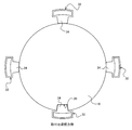
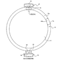
次に、上記実施形態のチャイルドシート10に適用可能な応用形態について、図面を参照しつつ説明する。なお、以下に示す応用形態は、いずれも、その殆どの構成を上述した実施形態に係るチャイルドシート10と同様とする。よって、各応用形態を示す図面に開示する特徴的な構成以外の構成は、上記実施形態に係るチャイルドシート10の構成を援用することとする。また、以下に示す応用形態では、主に、取付台座12と着座シート22の間に位置する回転機構の構成を模式的に示し、これを各応用形態の特徴的構成とする
まず、第1の応用形態について、図10を参照して説明する。本応用形態では、操作手段32の数を4つとしている。操作手段32を4つ設ける場合、各操作手段32間の配置角度は、約90度とすると良い。操作手段32をこのような形態で配置することで、着座シート22を約90度回転させる毎にロックがかかることとなる。本実施形態においても、ロックがかかる状態の時には、必ずロック解除に寄与することとなる操作手段32が取付台座12の前方に位置することとなる。また、ロック解除動作と着座シート22を回転させる動作を片手で同時に行うことも可能となる。
なお、上記実施形態では、支持面16において、凹部20の形成位置から約90度の位置に、平面視形状を直線とした切欠き部16bを設け、着座シート22を回転させる際に仮ロックを生じさせる旨記載した。しかしながら、本応用形態では、約90度毎にロックがかかる構成とするため、支持面16に切欠き部16bを設ける必要性は無い。
次に、第2の応用形態について、図11を参照して説明する。本応用形態では、凹部20の数を2つとしている。凹部20の数を増やす場合、その配置角度は、操作手段32の配置角度よりも小さくなるようにする。本応用形態では、2つの操作手段32の配置角度を約180度とし、2つの凹部20の配置角度を約90度としている(いずれも支持面16の中心を基点とする)。
なお、凹部20の配置位置は、取付台座12の前方側の位置を基点として、±90度の範囲に配置することが望ましい。凹部20の配置位置は、操作手段32によるロック、あるいはロック解除が成される位置である。このため、取付台座12の前方側の位置を基点とした±90度の範囲に凹部20を設けることで、ロック解除操作を行う操作手段32は、取付台座12の前方側か、側面側に位置することとなり、操作性を損なう虞が無い。
また、凹部20の配置角度を操作手段32の配置角度よりも小さくすることで、1つの操作手段32により凹部20とのロックを解除して着座シート22の回転操作を行っている最中に、他の操作手段32が凹部20に嵌合し、着座シート22の回転がロックされてしまうといった事態を生じさせる虞が無い。また、凹部20の数を増やすことで、着座シート22を回転させる際、任意の角度で着座シート22の回転をロックすることが可能となる。
次に、第3の応用形態について、図12を参照して説明する。本応用形態では、凹部20の数、操作手段32の数を共に3つとしている。凹部20や操作手段32の数を2つ以上に増やす場合には、最も離れた位置にある2つの凹部20の間の角度θ1が、隣り合って配置されている2つの操作手段32の配置角度θ2よりも小さくなるように配置することが望ましい。1つの操作手段32により凹部20とのロックを解除して着座シート22の回転操作を行っている最中に、他の操作手段32が凹部20に嵌合し、着座シート22の回転がロックされてしまうといった事態を避けるためである。
本応用形態では、隣り合う凹部20の配置角度をそれぞれ約30度、隣り合う操作手段32の配置角度をそれぞれ約120度としている。このような応用形態であっても、上述した第2の応用形態と同様の効果を発揮することが可能となる。
次に、第4の応用形態について、図13を参照して説明する。本応用形態では、凹部20の配置位置と操作手段32の付勢方向を異ならせる構成とした。上記実施形態では、操作手段32を構成するロック部34は、周回経路18を構成する壁面のうち、内周側壁面18aに付勢する構成としていた。これに対し、本応用形態では、周回経路18を構成する壁面のうち、外周側壁面18bに、ロック部34を付勢させる構成とする。すなわち、操作手段32には、回転板26(図7参照)の回転中心から離間する方向へ向けた付勢力が働くように、付勢手段(不図示)を設けるようにする。
また、本応用形態では、凹部20を外周側壁面18bに設ける構成としている。また、その配置位置は、取付台座12の前方側とすることが望ましい。
このように本応用形態では、ロック部34の付勢方向を周回経路18を構成する外周側壁面18bの方向とすることで、着座シート22の回転がロックされる際には、周回経路18の外周側壁面18bに形成された凹部20にロック部34が嵌合することとなる。このため、着座シート22のロックを解除する際には、操作手段32のロック解除部36を回転板26の回転中心方向へ押し込むこととなる。
次に、第5の応用形態について、図14、図15を参照して説明する。なお、図14は、回転機構の平面構成を示す模式図であり、図15は、図14におけるF-F断面を示す模式図である。本応用形態では、周回経路18を構成する壁面のうちの底面18cに、凹部20を構成している。このような構成では、溝状に形成された周回経路18に沿って摺動する操作手段32のロック部34が、凹部20に落ち込むことで、着座シート22の回転がロックされることとなる。
本応用形態の場合、着座シート22の回転ロックを解除する際には、操作手段32を構成するロック解除部36を上方へ引き上げれば良い。この動作により、凹部20に嵌合しているロック部34が引き抜かれることとなるからである。
次に、第6の応用形態について、図16を参照して説明する。ここで、図16は、本応用形態に係るチャイルドシート10における断面構成(図3におけるC-C断面に対応)を示す図であり、説明を容易にするために、着座シート22と取付台座12を分解した状態で示している。
本応用形態では、操作手段32のロック部34を本体34aと返し34bから成るフック形状に形成し、周回経路18も、このロック部34の形態に合わせた形状としている。ここで、フック部34を構成する本体34aは、本応用形態ではプレート本体28から取付台座側12側へ垂下する垂下部と、プレート本体28の回転中心に向けて突出している凸部とを有するL字状としている。返し34bは、本体34aの凸部からロック解除部36側へ向けて、前述した垂下部と平行に突出する突起部である。また、周回経路18の具体的形状の一例としては、ロック部34の本体34aが周回するL字溝19aと、L字溝19aの形成により構成される天井部16cに形成され、返し34bが周回することとなる天井溝19bから成る。そして、ロック部34が嵌合することとなる凹部20は、天井溝19bにおける取付台座12の前方側に対応する位置に設けられる。
このような構成では、操作手段32は、凹部20が形成されている天井部16c側に付勢されることとなる。そして、着座シート22の回転と共に操作手段32が天井溝19bの凹部20形成位置に到達すると、ロック部34の返し34bが凹部20に嵌合する。返し34bが凹部20に嵌合すると、凹部20の深さ分だけ、操作手段32のロック解除部36が、シート本体24側(図面上側)に突出し、着座シート22の回転がロックされることとなる。着座シート22の回転ロックを解除する場合には、突出している操作手段32のロック解除部36をプレート本体28側(図中下側)へ押し込めば良い。このような操作により、ロック部34の返し34bと凹部20との嵌合
外れ、ロックが解除されることとなる。
外れ、ロックが解除されることとなる。
このような構成であっても、操作手段32を片手で操作し、かつ着座シート22を回転させる力を加えることができる。このため、本発明の一部とみなすことができる。なお、図16においては、操作手段32や取付台座12をそれぞれ一体物として示しているため、組み付けが困難であるように見えるが、図16は、本応用形態の一例を模式的に示すものであり、各構成要素を適宜分割可能な構成とすれば、組み付け上の問題は生じない。
10………チャイルドシート、12………取付台座、14………回転ベース、16………支持面、16a………軸受け孔、16b………切欠き部、18………周回経路、18a………内周側壁面、18b………外周側壁面、18c………底面、20………凹部、22………着座シート、24………シート本体、24a………背もたれ部、24b………着座部、26………回転板、28………プレート本体、28a………開口部、30………回転軸、30a………抜け止め、32………操作手段、34………ロック部、36………ロック解除部。
Claims (4)
- 周回経路と、前記周回経路の少なくとも一部に形成された凹部とを有する回転ベースが付帯された取付台座と、 前記周回経路に沿った移動と前記凹部への嵌合を可能に配置されたロック部と、前記ロック部を前記凹部を形成した面側へ付勢させる付勢手段と、前記ロック部に接続されて前記ロック部を前記付勢手段による付勢方向と反対側へ移動させることで前記ロック部と前記凹部との嵌合を解除するロック解除部とを有する複数の操作手段を備え、前記回転ベースに対して回転可能に組付けられる回転板が付帯された着座シートと、 を有することを特徴とするチャイルドシート。
- 前記凹部は、前記周回経路上で、前記取付台座の前方側に対応する位置に設けられ、 前記複数の操作手段は、少なくとも前記着座シートの前方側に対応する位置と後方側に対応する位置に設けられていることを特徴とする請求項1に記載のチャイルドシート。
- 前記回転板の回転中心を基点として放射状に複数の前記凹部を設け、 前記回転中心を基点とした前記複数の凹部間の配置角度を前記回転中心を基点とした前記操作手段の配置角度よりも小さくしたことを特徴とする請求項2に記載のチャイルドシート。
- 前記周回経路を構成する壁面に前記ロック部の摺動抵抗を変化させる切欠き部を設けたことを特徴とする請求項1乃至3のいずれか1項に記載のチャイルドシート。
Priority Applications (1)
| Application Number | Priority Date | Filing Date | Title |
|---|---|---|---|
| EP15793086.8A EP3144178B1 (en) | 2014-05-14 | 2015-04-23 | Child seat |
Applications Claiming Priority (2)
| Application Number | Priority Date | Filing Date | Title |
|---|---|---|---|
| JP2014100273A JP6282927B2 (ja) | 2014-05-14 | 2014-05-14 | チャイルドシート |
| JP2014-100273 | 2014-05-14 |
Publications (1)
| Publication Number | Publication Date |
|---|---|
| WO2015174237A1 true WO2015174237A1 (ja) | 2015-11-19 |
Family
ID=54479781
Family Applications (1)
| Application Number | Title | Priority Date | Filing Date |
|---|---|---|---|
| PCT/JP2015/062343 WO2015174237A1 (ja) | 2014-05-14 | 2015-04-23 | チャイルドシート |
Country Status (3)
| Country | Link |
|---|---|
| EP (1) | EP3144178B1 (ja) |
| JP (1) | JP6282927B2 (ja) |
| WO (1) | WO2015174237A1 (ja) |
Cited By (3)
| Publication number | Priority date | Publication date | Assignee | Title |
|---|---|---|---|---|
| CN108237955A (zh) * | 2018-02-05 | 2018-07-03 | 安徽永驰婴童安全科技有限公司 | 儿童安全座椅及底座与椅体旋转连接结构 |
| CN114919475A (zh) * | 2022-04-28 | 2022-08-19 | 欧颂安全科技(湖北)有限公司 | 一种儿童安全座椅的一键解锁旋转调节结构 |
| WO2024034258A1 (ja) * | 2022-08-08 | 2024-02-15 | 株式会社カーメイト | チャイルドシート |
Families Citing this family (5)
| Publication number | Priority date | Publication date | Assignee | Title |
|---|---|---|---|---|
| CN109305073A (zh) * | 2017-07-26 | 2019-02-05 | 珠海阳光儿童用品有限公司 | 儿童安全座椅 |
| CN109606214A (zh) * | 2018-10-29 | 2019-04-12 | 宁波后乐婴童用品有限公司 | 一种儿童安全座椅 |
| CN113119821A (zh) * | 2019-12-30 | 2021-07-16 | 宝钜瑞士股份有限公司 | 角度调整结构及婴儿载具 |
| CN114789682A (zh) * | 2021-01-25 | 2022-07-26 | 宝钜瑞士股份有限公司 | 座椅旋转机构及儿童安全座椅 |
| CN113276740B (zh) * | 2021-05-24 | 2022-08-02 | 好孩子儿童用品有限公司 | 儿童汽车安全座椅 |
Citations (3)
| Publication number | Priority date | Publication date | Assignee | Title |
|---|---|---|---|---|
| JP2004504218A (ja) * | 2000-07-26 | 2004-02-12 | レノリュックス フランス アンデュストリ | 車両に取り付け可能な子供用安全装置 |
| JP2005193775A (ja) * | 2004-01-07 | 2005-07-21 | Fuso Engineering Corp | 車両用移動シート装置 |
| US20140084650A1 (en) * | 2011-04-29 | 2014-03-27 | Cosco Management, Inc. | Self-pivoting child car seat to be fitted to a vehicle seat |
Family Cites Families (2)
| Publication number | Priority date | Publication date | Assignee | Title |
|---|---|---|---|---|
| JP3288002B2 (ja) * | 1997-01-08 | 2002-06-04 | アップリカ▲葛▼西株式会社 | 自動車用年少者安全座席 |
| EP2295287B1 (fr) * | 2009-09-14 | 2012-08-01 | BÉBÉCAR - Utilidades para Criança, S.A. | Base de fixation pour un siège automobile pour enfant |
-
2014
- 2014-05-14 JP JP2014100273A patent/JP6282927B2/ja active Active
-
2015
- 2015-04-23 EP EP15793086.8A patent/EP3144178B1/en active Active
- 2015-04-23 WO PCT/JP2015/062343 patent/WO2015174237A1/ja active Application Filing
Patent Citations (3)
| Publication number | Priority date | Publication date | Assignee | Title |
|---|---|---|---|---|
| JP2004504218A (ja) * | 2000-07-26 | 2004-02-12 | レノリュックス フランス アンデュストリ | 車両に取り付け可能な子供用安全装置 |
| JP2005193775A (ja) * | 2004-01-07 | 2005-07-21 | Fuso Engineering Corp | 車両用移動シート装置 |
| US20140084650A1 (en) * | 2011-04-29 | 2014-03-27 | Cosco Management, Inc. | Self-pivoting child car seat to be fitted to a vehicle seat |
Cited By (4)
| Publication number | Priority date | Publication date | Assignee | Title |
|---|---|---|---|---|
| CN108237955A (zh) * | 2018-02-05 | 2018-07-03 | 安徽永驰婴童安全科技有限公司 | 儿童安全座椅及底座与椅体旋转连接结构 |
| CN108237955B (zh) * | 2018-02-05 | 2023-11-24 | 安徽永驰婴童科技股份有限公司 | 儿童安全座椅及底座与椅体旋转连接结构 |
| CN114919475A (zh) * | 2022-04-28 | 2022-08-19 | 欧颂安全科技(湖北)有限公司 | 一种儿童安全座椅的一键解锁旋转调节结构 |
| WO2024034258A1 (ja) * | 2022-08-08 | 2024-02-15 | 株式会社カーメイト | チャイルドシート |
Also Published As
| Publication number | Publication date |
|---|---|
| JP6282927B2 (ja) | 2018-02-21 |
| EP3144178A4 (en) | 2017-05-03 |
| EP3144178B1 (en) | 2020-06-17 |
| EP3144178A1 (en) | 2017-03-22 |
| JP2015217696A (ja) | 2015-12-07 |
Similar Documents
| Publication | Publication Date | Title |
|---|---|---|
| JP6282927B2 (ja) | チャイルドシート | |
| JP5051165B2 (ja) | 車両用シートリクライニング装置 | |
| US9527410B2 (en) | Hinge mechanism and vehicle seat comprising such a mechanism | |
| JP5434969B2 (ja) | 車両用シートリクライニング装置 | |
| JP5638994B2 (ja) | リクライニング装置 | |
| WO2012176738A1 (ja) | アームレスト及びシート | |
| JP3167699U (ja) | 換気口 | |
| US9108545B2 (en) | Reclining apparatus | |
| JP2016027968A (ja) | 車両用シートロック装置 | |
| JP6349905B2 (ja) | アンロックレバー装置 | |
| WO2012117772A1 (ja) | リクライニング装置 | |
| EP2963208A1 (en) | Lock for portable generators | |
| JP2016053291A (ja) | 打掛錠 | |
| JP5994151B2 (ja) | ドアロック装置のカウンタウェイト取付構造 | |
| KR101941589B1 (ko) | 레버 타입 dls 창호용 손잡이 | |
| JP2016188060A (ja) | 車両用シートスライド装置 | |
| WO2014147685A1 (ja) | マット用留め具 | |
| JP6732365B2 (ja) | ロック装置 | |
| JP5849242B2 (ja) | キャスタ | |
| JP6125374B2 (ja) | グローブボックス用操作装置 | |
| JP2008037158A (ja) | 車両用引出しテーブル構造 | |
| JP2010220937A (ja) | 車両用シートの連結装置 | |
| JP6361261B2 (ja) | アンロックレバー装置 | |
| JP6689522B2 (ja) | ロック装置 | |
| JP5615731B2 (ja) | 車両用シート |
Legal Events
| Date | Code | Title | Description |
|---|---|---|---|
| 121 | Ep: the epo has been informed by wipo that ep was designated in this application |
Ref document number: 15793086 Country of ref document: EP Kind code of ref document: A1 |
|
| REEP | Request for entry into the european phase |
Ref document number: 2015793086 Country of ref document: EP |
|
| WWE | Wipo information: entry into national phase |
Ref document number: 2015793086 Country of ref document: EP |
|
| NENP | Non-entry into the national phase |
Ref country code: DE |