WO2015174204A1 - Plating apparatus and container bath - Google Patents
Plating apparatus and container bath Download PDFInfo
- Publication number
- WO2015174204A1 WO2015174204A1 PCT/JP2015/061726 JP2015061726W WO2015174204A1 WO 2015174204 A1 WO2015174204 A1 WO 2015174204A1 JP 2015061726 W JP2015061726 W JP 2015061726W WO 2015174204 A1 WO2015174204 A1 WO 2015174204A1
- Authority
- WO
- WIPO (PCT)
- Prior art keywords
- plating
- space
- plating solution
- plated
- tank
- Prior art date
Links
Images


Classifications
-
- C—CHEMISTRY; METALLURGY
- C25—ELECTROLYTIC OR ELECTROPHORETIC PROCESSES; APPARATUS THEREFOR
- C25D—PROCESSES FOR THE ELECTROLYTIC OR ELECTROPHORETIC PRODUCTION OF COATINGS; ELECTROFORMING; APPARATUS THEREFOR
- C25D5/00—Electroplating characterised by the process; Pretreatment or after-treatment of workpieces
- C25D5/08—Electroplating with moving electrolyte e.g. jet electroplating
-
- C—CHEMISTRY; METALLURGY
- C23—COATING METALLIC MATERIAL; COATING MATERIAL WITH METALLIC MATERIAL; CHEMICAL SURFACE TREATMENT; DIFFUSION TREATMENT OF METALLIC MATERIAL; COATING BY VACUUM EVAPORATION, BY SPUTTERING, BY ION IMPLANTATION OR BY CHEMICAL VAPOUR DEPOSITION, IN GENERAL; INHIBITING CORROSION OF METALLIC MATERIAL OR INCRUSTATION IN GENERAL
- C23C—COATING METALLIC MATERIAL; COATING MATERIAL WITH METALLIC MATERIAL; SURFACE TREATMENT OF METALLIC MATERIAL BY DIFFUSION INTO THE SURFACE, BY CHEMICAL CONVERSION OR SUBSTITUTION; COATING BY VACUUM EVAPORATION, BY SPUTTERING, BY ION IMPLANTATION OR BY CHEMICAL VAPOUR DEPOSITION, IN GENERAL
- C23C18/00—Chemical coating by decomposition of either liquid compounds or solutions of the coating forming compounds, without leaving reaction products of surface material in the coating; Contact plating
- C23C18/16—Chemical coating by decomposition of either liquid compounds or solutions of the coating forming compounds, without leaving reaction products of surface material in the coating; Contact plating by reduction or substitution, e.g. electroless plating
- C23C18/1601—Process or apparatus
- C23C18/1619—Apparatus for electroless plating
- C23C18/1628—Specific elements or parts of the apparatus
- C23C18/163—Supporting devices for articles to be coated
-
- C—CHEMISTRY; METALLURGY
- C23—COATING METALLIC MATERIAL; COATING MATERIAL WITH METALLIC MATERIAL; CHEMICAL SURFACE TREATMENT; DIFFUSION TREATMENT OF METALLIC MATERIAL; COATING BY VACUUM EVAPORATION, BY SPUTTERING, BY ION IMPLANTATION OR BY CHEMICAL VAPOUR DEPOSITION, IN GENERAL; INHIBITING CORROSION OF METALLIC MATERIAL OR INCRUSTATION IN GENERAL
- C23C—COATING METALLIC MATERIAL; COATING MATERIAL WITH METALLIC MATERIAL; SURFACE TREATMENT OF METALLIC MATERIAL BY DIFFUSION INTO THE SURFACE, BY CHEMICAL CONVERSION OR SUBSTITUTION; COATING BY VACUUM EVAPORATION, BY SPUTTERING, BY ION IMPLANTATION OR BY CHEMICAL VAPOUR DEPOSITION, IN GENERAL
- C23C18/00—Chemical coating by decomposition of either liquid compounds or solutions of the coating forming compounds, without leaving reaction products of surface material in the coating; Contact plating
- C23C18/16—Chemical coating by decomposition of either liquid compounds or solutions of the coating forming compounds, without leaving reaction products of surface material in the coating; Contact plating by reduction or substitution, e.g. electroless plating
- C23C18/1601—Process or apparatus
- C23C18/1633—Process of electroless plating
- C23C18/1655—Process features
- C23C18/1664—Process features with additional means during the plating process
-
- C—CHEMISTRY; METALLURGY
- C25—ELECTROLYTIC OR ELECTROPHORETIC PROCESSES; APPARATUS THEREFOR
- C25D—PROCESSES FOR THE ELECTROLYTIC OR ELECTROPHORETIC PRODUCTION OF COATINGS; ELECTROFORMING; APPARATUS THEREFOR
- C25D17/00—Constructional parts, or assemblies thereof, of cells for electrolytic coating
- C25D17/02—Tanks; Installations therefor
-
- C—CHEMISTRY; METALLURGY
- C25—ELECTROLYTIC OR ELECTROPHORETIC PROCESSES; APPARATUS THEREFOR
- C25D—PROCESSES FOR THE ELECTROLYTIC OR ELECTROPHORETIC PRODUCTION OF COATINGS; ELECTROFORMING; APPARATUS THEREFOR
- C25D21/00—Processes for servicing or operating cells for electrolytic coating
- C25D21/10—Agitating of electrolytes; Moving of racks
-
- C—CHEMISTRY; METALLURGY
- C23—COATING METALLIC MATERIAL; COATING MATERIAL WITH METALLIC MATERIAL; CHEMICAL SURFACE TREATMENT; DIFFUSION TREATMENT OF METALLIC MATERIAL; COATING BY VACUUM EVAPORATION, BY SPUTTERING, BY ION IMPLANTATION OR BY CHEMICAL VAPOUR DEPOSITION, IN GENERAL; INHIBITING CORROSION OF METALLIC MATERIAL OR INCRUSTATION IN GENERAL
- C23C—COATING METALLIC MATERIAL; COATING MATERIAL WITH METALLIC MATERIAL; SURFACE TREATMENT OF METALLIC MATERIAL BY DIFFUSION INTO THE SURFACE, BY CHEMICAL CONVERSION OR SUBSTITUTION; COATING BY VACUUM EVAPORATION, BY SPUTTERING, BY ION IMPLANTATION OR BY CHEMICAL VAPOUR DEPOSITION, IN GENERAL
- C23C18/00—Chemical coating by decomposition of either liquid compounds or solutions of the coating forming compounds, without leaving reaction products of surface material in the coating; Contact plating
- C23C18/16—Chemical coating by decomposition of either liquid compounds or solutions of the coating forming compounds, without leaving reaction products of surface material in the coating; Contact plating by reduction or substitution, e.g. electroless plating
- C23C18/1601—Process or apparatus
- C23C18/1619—Apparatus for electroless plating
- C23C18/1632—Features specific for the apparatus, e.g. layout of cells and of its equipment, multiple cells
-
- C—CHEMISTRY; METALLURGY
- C25—ELECTROLYTIC OR ELECTROPHORETIC PROCESSES; APPARATUS THEREFOR
- C25D—PROCESSES FOR THE ELECTROLYTIC OR ELECTROPHORETIC PRODUCTION OF COATINGS; ELECTROFORMING; APPARATUS THEREFOR
- C25D17/00—Constructional parts, or assemblies thereof, of cells for electrolytic coating
- C25D17/005—Contacting devices
-
- C—CHEMISTRY; METALLURGY
- C25—ELECTROLYTIC OR ELECTROPHORETIC PROCESSES; APPARATUS THEREFOR
- C25D—PROCESSES FOR THE ELECTROLYTIC OR ELECTROPHORETIC PRODUCTION OF COATINGS; ELECTROFORMING; APPARATUS THEREFOR
- C25D17/00—Constructional parts, or assemblies thereof, of cells for electrolytic coating
- C25D17/06—Suspending or supporting devices for articles to be coated
-
- C—CHEMISTRY; METALLURGY
- C25—ELECTROLYTIC OR ELECTROPHORETIC PROCESSES; APPARATUS THEREFOR
- C25D—PROCESSES FOR THE ELECTROLYTIC OR ELECTROPHORETIC PRODUCTION OF COATINGS; ELECTROFORMING; APPARATUS THEREFOR
- C25D17/00—Constructional parts, or assemblies thereof, of cells for electrolytic coating
- C25D17/10—Electrodes, e.g. composition, counter electrode
-
- C—CHEMISTRY; METALLURGY
- C25—ELECTROLYTIC OR ELECTROPHORETIC PROCESSES; APPARATUS THEREFOR
- C25D—PROCESSES FOR THE ELECTROLYTIC OR ELECTROPHORETIC PRODUCTION OF COATINGS; ELECTROFORMING; APPARATUS THEREFOR
- C25D3/00—Electroplating: Baths therefor
- C25D3/02—Electroplating: Baths therefor from solutions
- C25D3/38—Electroplating: Baths therefor from solutions of copper
Definitions
- the present invention relates to a plating apparatus and a storage tank.
- the anode member or cathode member is more likely to be baked and there is a risk of incurring plating defects. It is known to increase.
- Patent Documents 1 and 2 As a technique for preventing defective plating while increasing productivity at a high current, an injection type plating apparatus that performs a plating process by injecting a plating solution from a plurality of nozzles toward an object to be plated is known (for example, Patent Documents 1 and 2).
- the conventional spray type plating apparatus has a problem that a place where the plating solution is easy to hit and a place where it is hard to hit are generated, resulting in variations in plating thickness.
- the present invention was created from such a viewpoint, and an object of the present invention is to provide a plating apparatus and a storage tank capable of improving the uniformity of the plating thickness with a simpler structure than before.
- the present invention provides a plating tank that contains a plating solution, an anode member disposed inside the plating tank, and a plating target disposed inside the plating tank so as to face the anode member.
- a plating apparatus comprising: an object; a cathode member that contacts the object to be plated; and a space that is formed between the anode member and the object to be plated and serves as a flow path for the plating solution to flow from the plating tank.
- the plating solution flows from above the space and is sucked by a pump from below the space.
- the plating solution flows from above the space and is sucked by the pump from below the space, the flow rate of the plating solution in the space increases. Therefore, the plating solution can easily hit the object to be plated, and the plating thickness uniformity can be improved.
- the present invention eliminates the need for a nozzle, a drive mechanism, etc., the plating apparatus can be simplified and downsized, and the cost can be reduced.
- the space has a structure in which both side portions in a direction orthogonal to the facing direction of the anode member and the object to be plated are closed.
- the space is closed on both sides in the direction orthogonal to the facing direction of the anode member and the object to be plated, it becomes possible to prevent the infiltration of the plating solution from the side of the space, The flow of the plating solution can be made into a laminar flow parallel to the object to be plated.
- the plating tank has a first holding part that detachably holds the anode member and a second holding part that detachably holds the object to be plated.
- the plating tank has the first holding part that detachably holds the anode member and the second holding part that detachably holds the object to be plated. While positioning a member and a to-be-plated object can be performed easily, an anode member and a to-be-plated object can be hold
- the width dimension of the space along the facing direction of the anode member and the object to be plated is formed to have a width dimension so that the flow of the plating solution is a laminar flow parallel to the object to be plated. Is preferable.
- the flow rate of the plating solution in the space can be increased, and the flow of the plating solution can be made into a laminar flow parallel to the object to be plated.
- this invention is a storage tank arrange
- the plating solution flows from above the space and is sucked by the pump from below the space, the flow rate of the plating solution in the space increases. Therefore, the plating solution can easily hit the object to be plated, and the plating thickness uniformity can be improved.
- the present invention eliminates the need for a nozzle, a drive mechanism, etc., the plating apparatus can be simplified and downsized, and the cost can be reduced.
- a storage tank can be put into an existing plating tank and used, it has the advantage that versatility is high.
- the present invention provides a plating tank that contains a plating solution, a wall portion of the plating tank, and an object to be plated disposed inside the plating tank so as to face the wall portion,
- a plating apparatus comprising: a space formed between the wall portion and the object to be plated and serving as a flow path into which the plating solution flows from the plating tank, wherein the plating solution is from above the space. It flows in and is sucked by a pump from below the space.
- the present invention is a storage tank disposed inside a plating tank capable of storing a plating solution, and is stored in a wall part of the storage tank, and is opposed to the wall part. And the space to be plated, and a space that is formed between the wall portion and the object to be plated and into which the plating solution flows from the plating tank. It flows from above the space, and is sucked by a pump from below the space.
- the present invention since the plating solution flows from above the space and is sucked by the pump from below the space, the flow rate of the plating solution in the space increases. Therefore, the plating solution can easily hit the object to be plated, and the plating thickness uniformity can be improved.
- the present invention eliminates the need for a nozzle, a drive mechanism, etc., the plating apparatus can be simplified and downsized, and the cost can be reduced.
- the present invention it is possible to provide a plating apparatus and a storage tank capable of improving the uniformity of the plating thickness with a simpler structure than before.
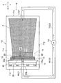
- FIG. 1 is a longitudinal sectional view showing a plating apparatus according to a first embodiment of the present invention.
- FIG. 2 is a partially enlarged plan view of FIG. 1.
- It is a longitudinal cross-sectional view which shows the plating apparatus which concerns on 2nd Embodiment of this invention.
- It is a decomposition
- the plating apparatus M includes a plating tank 10, an anode member 20, a cathode jig 30, a space 40, and a pump 50.
- the dot hatching in FIG. 1 shows the staying part of the plating solution F.
- the plating tank 10 has a function of containing a plating solution F as shown in FIGS.
- the plating tank 10 includes a bottom portion 11a, a pair of side portions 11b and 11c that face each other in the orthogonal direction Y, and a pair of side portions 11d and 11e that face each other in the facing direction X.
- the plating solution F is accommodated only in a region on the opposite side of the space 40 across the anode member 20 (vertical wall 12) in the plating tank 10.
- the plating tank 10 has a rectangular shape in plan view, and is installed so that the longitudinal direction coincides with the facing direction X. In addition, you may change suitably the shape, material, etc. of the plating tank 10.
- the plating tank 10 includes a vertical wall 12 projecting upward from the inner surface of the bottom portion 11 a of the plating tank 10, a first holding part 13 that holds the anode member 20 detachably, The second holding part 14 that holds the cathode jig 30 in a detachable manner, the plating communication hole 15 that communicates the first holding part 13 and the space 40, and the suction hole 16 and the discharge hole 17 through which the plating solution F passes.
- the vertical wall 12 which is a wall portion is a wall-shaped portion provided on the side portion 11 d side of the plating tank 10. Both side portions of the vertical wall 12 in the orthogonal direction Y are continuously formed integrally with the inner surfaces of the side portions 11b and 11c (see FIG. 1) of the plating tank 10. The upper part of the vertical wall 12 is located below the liquid level of the plating solution F and the upper ends of the side portions 11b to 11e. With such a configuration, the plating solution F flows into the space 40 beyond the vertical wall 12 as described later.
- the vertical wall 12 may be formed separately from the plating tank 10 and attached to the plating tank 10.
- the first holding part 13 is a groove-like and slit-like hole whose upper part is open.
- the first holding part 13 is formed from the upper part to the lower part of the vertical wall 12 and is provided at a position near the cathode jig 30 on the vertical wall 12.
- the anode member 20 is inserted and held in the first holding portion 13.
- the second holding part 14 is a part formed in an uneven shape in accordance with the outer shape of the cathode jig 30.
- the second holding part 14 is formed on the inner surfaces of the side parts 11 b and 11 c of the plating tank 10.
- a cathode jig 30 is inserted and held in the second holding portion 14.
- the second holding part 14 holds the overhang part 30 a formed at the end of the cathode jig 30 on the anode member 20 side from both sides in the facing direction X.
- the cathode jig 30 may be held on the vertical wall 12 and the anode member 20 may be held on the side portions 11 b and 11 c of the plating tank 10.
- the plating communication hole 15 is a through hole that exposes the anode member 20 to the space 40 side.
- the plating communication hole 15 is formed in an intermediate portion in the vertical direction of the vertical wall 12.
- the suction hole 16 is a through hole that becomes a part of the suction channel C1 through which the plating solution F sucked from the space 40 by the pump 50 passes.
- the suction hole 16 is formed to penetrate from the upper surface to the side surface of the bottom portion 11a of the plating tank 10.
- the suction hole 16 extends downward from the upper surface of the bottom portion 11a and then extends toward one side in the facing direction X.
- One end of the suction hole 16 opens at the lower part of the space 40.
- a suction pipe 60 that connects the suction hole 16 and the pump 50 is connected to the other end of the suction hole 16. That is, in the present embodiment, the suction flow path C1 is configured by the suction hole 16 and the suction pipe 60.
- the discharge hole 17 is a through hole that becomes a part of the discharge flow path C2 through which the plating solution F discharged from the pump 50 passes.
- the discharge hole 17 is formed to penetrate from the outer surface to the inner surface of the side portion 11e of the plating tank 10.
- One end of the discharge hole 17 opens in a region on the opposite side of the space 40 with the anode member 20 interposed therebetween in the plating tank 10.
- a discharge pipe 70 that connects the discharge hole 17 and the pump 50 is connected to the other end of the discharge hole 17. That is, in the present embodiment, the discharge flow path C ⁇ b> 2 is configured by the discharge hole 17 and the discharge pipe 70.
- the anode member 20 is a rectangular and plate-shaped metal member disposed inside the plating tank 10.
- the anode member 20 is formed such that a central portion 21 along the orthogonal direction Y is positioned below both end portions 22 and 23 along the orthogonal direction Y.
- the upper end of the central portion 21 of the anode member 20 is formed horizontally and is located at the same height as the upper portion of the vertical wall 12.
- the upper ends of both end portions 22 and 23 of the anode member 20 protrude upward from the surface of the plating solution F. With such a configuration, the plating solution F flows into the space 40 beyond only the central portion 21 of the anode member 20 as described later.
- Both end portions 22 and 23 of the anode member 20 are connected to the + (plus; positive) pole of the power source 80 via the connection line H1.
- the cathode jig 30 has a function as a cathode member and a function of holding the workpiece W.
- the cathode jig 30 and the workpiece W are arranged inside the plating tank 10 so as to face the anode member 20.
- the cathode jig 30 includes a pair of holding members 31 and 32 that sandwich the object to be plated W, and an electrode member 33 that contacts the object to be plated W and transmits electricity from the power source 80. Have.
- the holding member 32 disposed on the space 40 side is formed with a plating opening 32a penetrating in the horizontal direction.
- the plating opening 32a exhibits the function of exposing the object to be plated W to the space 40 side and bringing the plating solution F into contact with the object to be plated W.
- the electrode member 33 includes an annular contact portion 33 a that contacts the periphery of the workpiece W and a strip-shaped power connection portion 33 b that is connected to the power source 80.
- the power supply connection portion 33 b is inserted into an insertion hole 32 b formed inside the holding member 32.
- the upper side of the power supply connecting portion 33b is located above the liquid surface of the plating solution F.
- the power supply connection portion 33b is connected to the ⁇ (minus; negative) pole of the power supply 80 via the connection line H2.
- the upper part of the cathode jig 30 is located above the upper surface of the plating solution F, and both side parts in the orthogonal direction Y are in contact with the inner surfaces of the side parts 11b and 11c of the plating tank 10 without a gap.
- the plating solution F flowing into the space 40 from the anode member 20 side can be prevented from entering the back side of the cathode jig 30.
- the configuration of the cathode jig 30 may be changed as appropriate, or a cathode plate may be used instead of the cathode jig 30.
- the space 40 is formed between the anode member 20 and the cathode jig 30 (the object to be plated W) and functions as a channel through which the plating solution F flows from the plating tank 10.
- the space 40 is a slit-like narrow space having an upper opening. Both side portions of the space 40 in the orthogonal direction Y are closed by the side portions 11 b and 11 c of the plating tank 10.
- the space 40 is formed such that the dimension D1 along the facing direction X is smaller than the dimension D2 along the orthogonal direction Y (D1 ⁇ D2).
- the dimension D1 along the facing direction X is preferably about 1 mm to 30 mm, for example.
- the flow rate of the plating solution F flowing through the space 40 is preferably about 0.1 to 3 m / s, for example.
- the flow rate of the plating solution F is related to the dimension D1 along the facing direction X of the space 40, the performance of the pump 50, and the like, and can be adjusted by appropriately changing these.
- the pump 50 is disposed outside the plating tank 10.
- the pump 50 has a function of sucking the plating solution F from the space 40 and discharging the sucked plating solution F to the plating tank 10.
- the plating apparatus M according to the first embodiment of the present invention is basically configured as described above. Next, the operation and effect thereof will be described.
- the plating solution F in the space 40 is sucked. With this suction action, the plating solution F in the plating tank 10 flows into the space 40 from above over the vertical wall 12 and the central portion 21 of the anode member 20.
- the plating solution F does not enter from the side of the space 40. Moreover, since the plating solution F is accommodated only in the region opposite to the space 40 across the anode member 20 in the plating tank 10, the plating solution F is from only the anode member 20 side (only one in the facing direction X). Enter the space 40. Thereby, the flow of the plating solution F from the plating tank 10 to the space 40 is made smooth (suppressing that the plating solutions F interfere with each other as much as possible). As a result, the flow of the plating solution F in the space 40 is disturbed. Can be suppressed.
- the plating solution F flows from the upper side to the lower side in the space 40.
- the power source 80 is turned on and a current is passed through the anode member 20 and the electrode member 33, the metal ions in the plating solution F are attracted to the cathode jig 30 side and are deposited on the workpiece W to form a plating layer. Is done.
- the plating thickness can be adjusted by appropriately changing the flow rate of the plating solution F in the space 40 and the current value of the power source 80.
- the plating solution F is sucked by the pump 50 from below the space 40 and flows toward the pump 50 through the suction flow path C1.
- the plating solution F that has reached the pump 50 is discharged from the pump 50 and then returns to the plating tank 10 through the discharge channel C2.
- the plating solution F flows from above the space 40 and is sucked by the pump 50 from below the space 40, the flow rate of the plating solution F in the space 40 increases. Therefore, it becomes easy for the plating solution F to hit the workpiece W uniformly, and the uniformity of the plating thickness can be improved.
- a nozzle, a driving mechanism, and the like are not necessary, so that the plating apparatus M can be simplified and downsized, and the cost can be reduced.
- the plating solution F in the space 40 is replaced, even if a large current is supplied from the power supply 80, the anode member 20 and the electrode member 33 are less likely to be baked, and the occurrence of plating defects is suppressed. it can. Therefore, the plating layer can be grown quickly and uniformly, and productivity can be improved.
- the plating solution F in the space 40 is increased in flow rate and the plating solution F in the space 40 is replaced, so that the electrolytic plating is performed at a current density of about 4 to 5 A / dm 2.
- the plating time can be shortened.
- both sides of the space 40 in the orthogonal direction Y are closed by the plating tank 10, it is possible to prevent the plating solution F from entering from the side of the space 40.
- the dimension D1 of the space 40 along the facing direction X is a narrow width of about 1 mm to 30 mm, for example. Thereby, the flow of the plating solution F can be made into a laminar flow parallel to the workpiece W.
- the plating tank 10 includes the first holding part 13 that holds the anode member 20 in a detachable manner and the second holding part 14 that holds the cathode jig 30 in a detachable manner.
- the anode member 20 and the cathode jig 30 (the object to be plated W) can be easily positioned with respect to the plating tank 10, and the anode member 20 and the cathode jig 30 can be securely held.
- the space 40 is formed between the anode member 20 and the cathode jig 30 (the object to be plated W), and the plating solution F is allowed to flow from the upper side to the lower side of the space 40. Even when 50 is used, the flow rate of the plating solution F can be sufficiently secured. And the further miniaturization of the plating apparatus M is realizable by using the small pump 50.
- the plating solution F is circulated by the pump 50, it is possible to reuse the plating solution F and save waste.
- the plating apparatus M according to the second embodiment includes a storage tank 90 that stores the anode member 20 and the cathode jig 30, and uses a general plating tank 10 that does not include the first holding unit 13 and the second holding unit 14. This is different from the first embodiment.
- the anode member 20, the cathode jig 30, and the pump 50 are the same as those in the first embodiment, and thus description thereof is omitted.
- the storage tank 90 is disposed inside the plating tank 10 and has a function of storing the anode member 20 and the cathode jig 30.
- the storage tank 90 includes a bottom portion 90a, a pair of side portions 90b and 90c facing each other in the orthogonal direction Y, and a pair of side portions 90d and 90e facing each other in the facing direction X. It is a resin container. The shape and material of the storage tank 90 may be changed as appropriate.
- the storage tank 90 includes a first holding portion 91 that detachably holds the anode member 20, a second holding portion 92 that detachably holds the cathode jig 30, and the anode member 20 and the cathode jig 30 (to-be-plated object W).
- the first holding portion 91 is a groove-like and slit-like hole having an upper opening.
- maintenance part 91 is formed ranging from the upper part of the side part 90e to the lower part, and is provided in the position near the cathode jig 30 of the side part 90e.
- the anode member 20 is inserted and held in the first holding portion 91.
- the upper part of the side part 90e is located below the liquid level of the plating solution F and the upper ends of the side parts 11b to 11e. With such a configuration, the plating solution F flows into the space 93 beyond the upper portion of the side portion 90e as will be described later. Note that the upper end of the central portion 21 of the anode member 20 is located at the same height as the upper portion of the side portion 90e.
- the second holding portion 92 is a portion formed in an uneven shape in accordance with the outer shape of the cathode jig 30.
- the second holding portion 92 is formed on the inner surfaces of the side portions 90 b and 90 c of the storage tank 90.
- the cathode jig 30 is inserted and held in the second holding portion 92.
- the second holding portion 92 holds the overhang portion 30a (see FIG. 7) formed at the end of the cathode jig 30 on the anode member 20 side from both sides in the facing direction X.
- the upper part of the side part 90d is located above the upper surface of the plating solution F and the upper ends of the side parts 11b to 11e.
- the cathode jig 30 may be held on the side portion 90e, and the anode member 20 may be held on the side portions 90b and 90c.
- the space 93 is formed between the anode member 20 and the cathode jig 30 (the object to be plated W) and functions as a flow path into which the plating solution F flows from the plating tank 10.
- the space 93 is a slit-like narrow space having upper and lower openings. Both side portions in the orthogonal direction Y of the space 93 are closed by the side portions 90 b and 90 c in the orthogonal direction Y of the storage tank 90.
- the space 93 is formed such that the dimension D1 along the facing direction X is smaller than the dimension D2 along the orthogonal direction Y (D1 ⁇ D2).
- the dimension D1 along the facing direction X is preferably about 1 mm to 30 mm, for example.
- the flow rate of the plating solution F flowing through the space 93 is preferably about 0.1 to 3 m / s, for example.
- the flow rate of the plating solution F is related to the dimension D1 along the facing direction X of the space 93 and the performance of the pump 50, and can be adjusted by appropriately changing these.
- the lower portion 93 a of the space 93 extends below the first holding portion 91 and the second holding portion 92 and opens to the bottom portion 90 a of the storage tank 90.
- the lower 93a side of the space 93 is formed so as to increase in width from the upper side to the lower side in a longitudinal sectional view along the facing direction X.
- the lower 93 a side of the space 93 is formed so as to become narrower from the upper side to the lower side in a longitudinal sectional view along the orthogonal direction Y.
- the plating communication hole 94 is a through hole that exposes the anode member 20 to the space 93 side.
- the plating communication hole 94 is formed at a position below the upper portion of the side portion 90e.
- connection part 95 is a part that becomes a part of the suction channel C1 through which the plating solution F sucked from the space 93 by the pump 50 passes.
- One end of the connection part 95 is connected to the lower part 93 a of the space 93.
- a suction pipe 60 that connects the connection portion 95 and the pump 50 is connected to the other end portion of the connection portion 95. That is, in this embodiment, the suction channel C ⁇ b> 1 is configured by the connection portion 95 and the suction pipe 60.
- the discharge pipe 70 which becomes the discharge flow path C2 through which the plating solution F discharged from the pump 50 passes is connected to the pump 50.
- One end of the discharge pipe 70 opens in a region on the opposite side of the space 93 with the anode member 20 interposed therebetween in the plating tank 10. That is, in the present embodiment, the discharge flow path C2 is configured by only the discharge pipe 70.
- the plating apparatus M according to the second embodiment of the present invention is basically configured as described above. Next, its operation and effects will be described.
- the plating solution F in the space 93 is sucked. With this suction action, the plating solution F in the plating tank 10 flows into the space 93 from above over the upper part of the side part 90 e and the central part 21 of the anode member 20.
- the plating solution F does not enter from the side of the space 93.
- the upper part of the side part 90e is located below the liquid surface of the plating solution F, and the upper part of the side part 90d is located above the upper surface of the plating solution F, the plating solution F is on the anode member 20 side. Only enters (only one of the opposing directions X) into the space 93. Thereby, the flow of the plating solution F from the plating tank 10 to the space 93 is made smooth (suppressing that the plating solutions F interfere with each other as much as possible). As a result, the flow of the plating solution F in the space 93 is disturbed. Can be suppressed.
- the plating solution F flows in the space 93 from the top to the bottom.
- the power source 80 is turned on and a current is passed through the anode member 20 and the electrode member 33, the metal ions in the plating solution F are attracted to the cathode jig 30 side and are deposited on the workpiece W to form a plating layer. Is done.
- the plating thickness can be adjusted by appropriately changing the flow rate of the plating solution F in the space 93 and the current value of the power source 80.
- the plating solution F is sucked by the pump 50 from below the space 93 and flows toward the pump 50 through the suction flow path C1.
- the plating solution F that has reached the pump 50 is discharged from the pump 50 and then returns to the plating tank 10 through the discharge channel C2.
- the storage tank 90 can be used in the existing plating tank 10, it has the advantage that versatility is high.
- the third embodiment is different from the first embodiment in that the plating apparatus M according to the present invention is used for electroless plating. That is, the point which is not provided with the anode member 20, the cathode jig 30, etc. is different from 1st Embodiment.
- the same elements as those in the first embodiment are denoted by the same reference numerals as those in the first embodiment, and redundant descriptions are omitted.
- the plating apparatus M includes a plating tank 10, an object to be plated W, a space 40, and a pump 50.
- the vertical wall 12 of the plating tank 10 of the present embodiment is different from the first embodiment in that the first holding portion 13 and the communication hole 15 for plating are not provided.
- the to-be-plated object W is arrange
- the upper part of the workpiece W shown in FIG. 8 is located at the same height as the upper surface of the plating solution F. Although not shown, the upper part of the workpiece W may be positioned above or below the upper surface of the plating solution F. Both side portions in the orthogonal direction Y of the workpiece W are in contact with the inner surfaces of the side portions 11b and 11c of the plating tank 10 without any gap (only the side portion 11c is shown in FIG. 8). Although not shown in the drawing, the workpiece W is held vertically with respect to the plating tank 10 by a holding part or the like formed in the plating tank 10, for example.
- the space 40 is formed between the vertical wall 12 and the workpiece W, and functions as a flow path into which the plating solution F flows from the plating tank 10.
- the flow rate of the plating solution F flowing through the space 40 is preferably about 0.1 to 3 m / s, for example.
- the flow rate of the plating solution F is more preferably about 0.1 m / s.
- the vertical wall 12 may be omitted, and a space 40 may be formed between the side portion 11d of the plating tank 10 and the workpiece W, or between the side portion 11e of the plating tank 10 and the workpiece W.
- a space 40 may be formed.
- the positions of the suction channel C1, the discharge channel C2, and the like are changed as appropriate.
- the side parts 11d and 11e of the plating tank 10 comprise the wall part of a claim.
- the fourth embodiment is different from the second embodiment in that the plating apparatus M according to the present invention is used for electroless plating. That is, the point which is not provided with the anode member 20, the cathode jig 30, etc. is different from 2nd Embodiment.
- the same elements as those of the second embodiment are denoted by the same reference numerals as those of the second embodiment, and redundant descriptions are omitted.
- the storage tank 90 is disposed inside the plating tank 10 and has a function of storing the workpiece W.
- the storage tank 90 includes an object to be plated W, a space 93 formed between the side part 90e and the object to be plated W, and a connection part 95 connected to the lower part (downstream end) of the space 93. ing.
- the storage tank 90 of this embodiment is different from the second embodiment in that it does not have the first holding part 91, the second holding part 92, and the plating communication hole 94.
- the to-be-plated object W is arrange
- the space 93 is formed between the side portion 90e and the workpiece W, and functions as a flow path into which the plating solution F flows from the plating tank 10.
- a lower portion 93 a of the space 93 extends below the workpiece W and opens to the bottom 90 a of the storage tank 90.
- the flow rate of the plating solution F flowing through the space 93 is preferably about 0.1 to 3 m / s, for example. When electroless plating as in this embodiment is performed, the flow rate of the plating solution F is more preferably about 0.1 m / s.
- a space 93 may be formed between the side portion 90d of the storage tank 90 and the workpiece W.
- the positions of the suction channel C1, the discharge channel C2, and the like are changed as appropriate, and the upper portion of the side portion 90d is positioned below the surface of the plating solution F.
- the side part 90d of the storage tank 90 comprises the wall part of a claim.
- the plating solution F enters the spaces 40 and 93 from only the anode member 20 side (only one in the facing direction X), but the present invention is not limited to this. .
- the plating solution F may enter the spaces 40 and 93 from only the cathode jig 30 side (only the other in the facing direction X), or both the anode member 20 side and the cathode jig 30 side (both in the facing direction X). It is good also as a structure which infiltrates into space 40,93 from.
- the plating solution F enters the space 40 from only the vertical wall 12 side (only one in the facing direction X), but the present invention is not limited to this.
- the plating solution F may enter the space 40 only from the workpiece W side (only the other in the facing direction X), or both the vertical wall 12 side and the workpiece W side (both in the facing direction X). It is good also as a structure which penetrates into the space 40 from.
- the plating solution F enters the space 93 only from the side portion 90e side (only one in the facing direction X), but the present invention is not limited to this.
- the plating solution F may enter the space 93 only from the side 90d side (only the other in the facing direction X), or may enter the space 93 from both the side 90d and 90e sides (both in the facing direction X). It is good also as composition to do.
- a stirring rod (not shown) can be taken in and out from above the spaces 40 and 93.
- the stirring rod may be configured to swing along the orthogonal direction Y by a drive motor to stir the plating solution F in the space 40.
- a plurality of stirring spats may be provided, and the plating solution F may be stirred by changing the angle of the spatula.
- the plating solution F is circulated by the pump 50.
- the present invention is not limited to this, and the plating solution F sucked by the pump 50 is discharged to obtain a new plating solution F. It is also possible to use a configuration in which the is poured into the plating tank 10.
- M plating apparatus 10 plating tanks 11b to 11e side portion 13 first holding portion 14 second holding portion 20 anode member 30 cathode jig (cathode member) 40 space 50 pump 60 suction pipe 70 discharge pipe 80 power supply 90 storage tank 90b to 90e side part 91 first holding part 92 second holding part 93 space C1 suction flow path C2 discharge flow path F plating solution W plating object X facing direction Y orthogonal direction
Landscapes
- Chemical & Material Sciences (AREA)
- Engineering & Computer Science (AREA)
- Chemical Kinetics & Catalysis (AREA)
- Materials Engineering (AREA)
- Metallurgy (AREA)
- Organic Chemistry (AREA)
- Electrochemistry (AREA)
- General Chemical & Material Sciences (AREA)
- Mechanical Engineering (AREA)
- Electroplating Methods And Accessories (AREA)
Abstract
Description
さらに、前記課題を解決するため本発明は、めっき液を収容可能なめっき槽の内部に配置される収容槽であって、当該収容槽の壁部と、内部に収容され、前記壁部と対向して配置された被めっき物と、前記壁部と前記被めっき物との間に形成され、前記めっき槽から前記めっき液が流れ込む流路となる空間と、を備え、前記めっき液は、前記空間の上方から流れ込み、かつ、前記空間の下方からポンプで吸引されることを特徴とする。 In order to solve the above problems, the present invention provides a plating tank that contains a plating solution, a wall portion of the plating tank, and an object to be plated disposed inside the plating tank so as to face the wall portion, A plating apparatus comprising: a space formed between the wall portion and the object to be plated and serving as a flow path into which the plating solution flows from the plating tank, wherein the plating solution is from above the space. It flows in and is sucked by a pump from below the space.
Furthermore, in order to solve the above-mentioned problem, the present invention is a storage tank disposed inside a plating tank capable of storing a plating solution, and is stored in a wall part of the storage tank, and is opposed to the wall part. And the space to be plated, and a space that is formed between the wall portion and the object to be plated and into which the plating solution flows from the plating tank. It flows from above the space, and is sucked by a pump from below the space.
めっき槽10は、図1,図2に示すように、めっき液Fを収容する機能を備えている。めっき槽10は、底部11aと、直交方向Yで対向する一対の側部11b,11cと、対向方向Xで対向する一対の側部11d,11eとを備え、上部が開口した箱状かつ樹脂製の容器である。めっき液Fは、めっき槽10のうち陽極部材20(鉛直壁12)を挟んで空間40と反対側の領域のみに収容されている。めっき槽10は、平面視矩形状を呈し、長手方向が対向方向Xと一致するように設置されている。なお、めっき槽10の形状や材質などは適宜変更してよい。 <Plating tank>
The
陽極部材20は、図1,図2に示すように、めっき槽10の内部に配置された矩形状かつ板状の金属製部材である。陽極部材20は、直交方向Yに沿った中央部21が、直交方向Yに沿った両端部22,23よりも下方に位置するように形成されている。陽極部材20の中央部21の上端は、水平に形成され、鉛直壁12の上部と同じ高さに位置している。陽極部材20の両端部22,23の上端は、めっき液Fの液面よりも上方へ突出している。このような構成により、めっき液Fは、後記するように陽極部材20の中央部21のみを超えて空間40へ流れ込む。陽極部材20の両端部22,23は、接続線H1を介して、電源80の+(プラス;正)極に接続されている。 <Anode member>
As shown in FIGS. 1 and 2, the
陰極冶具30は、図1,図2に示すように、陰極部材としての機能を備えるとともに、被めっき物Wを保持する機能を備える。陰極冶具30及び被めっき物Wは、陽極部材20と対向するようにめっき槽10の内部に配置されている。
陰極冶具30は、図2に示すように、被めっき物Wを挟持する一対の保持部材31,32と、被めっき物Wに接触して電源80からの電気を伝達する電極部材33と、を有している。 <Cathode jig>
As shown in FIGS. 1 and 2, the
As shown in FIG. 2, the
空間40は、図1,図2に示すように、陽極部材20と陰極冶具30(被めっき物W)との間に形成され、めっき槽10からめっき液Fが流れ込む流路として機能する。空間40は、上部が開口したスリット状の狭小空間である。空間40の直交方向Yの両側部は、めっき槽10の側部11b,11cによって閉塞されている。空間40は、図3に示すように、対向方向Xに沿った寸法D1が直交方向Yに沿った寸法D2よりも小さく形成されている(D1<D2)。対向方向Xに沿った寸法D1は、例えば1mm~30mm程度とするのが好ましい。また、空間40を流れるめっき液Fの流速は、例えば0.1~3m/s程度とするのが好ましい。めっき液Fの流速は、空間40の対向方向Xに沿った寸法D1やポンプ50の性能などに関係し、これらを適宜変更することで調整できる。 <Space>
As shown in FIGS. 1 and 2, the
ポンプ50は、図1,図2に示すように、めっき槽10の外部に配置されている。ポンプ50は、空間40からめっき液Fを吸引するとともに、吸引しためっき液Fをめっき槽10へ吐出する機能を備えている。 <Pump>
As shown in FIGS. 1 and 2, the
また、本実施形態によれば、既存のめっき槽10に収容槽90を入れて使用することができるので、汎用性が高いという利点を有する。 According to the present embodiment described above, it is possible to obtain substantially the same operational effects as the first embodiment.
Moreover, according to this embodiment, since the
なお、鉛直壁12を省略し、めっき槽10の側部11dと被めっき物Wとの間に空間40を形成してもよいし、めっき槽10の側部11eと被めっき物Wとの間に空間40を形成してもよい。この場合には、吸引流路C1や吐出流路C2等の位置を適宜変更する。また、かかる構成においては、めっき槽10の側部11d,11eが請求の範囲の壁部を構成する。 According to the present embodiment described above, it is possible to obtain substantially the same operational effects as the first embodiment.
The
収容槽90は、被めっき物Wと、側部90eと被めっき物Wとの間に形成された空間93と、空間93の下部(下流端)に接続された接続部95と、を有している。本実施形態の収容槽90は、第1保持部91、第2保持部92、及び、めっき用連通孔94を有していない点が第2実施形態と相違している。 The
The
なお、例えば、収容槽90の側部90dと被めっき物Wとの間に空間93を形成してもよい。この場合には、吸引流路C1や吐出流路C2等の位置を適宜変更するとともに、側部90dの上部をめっき液Fの液面よりも下方に位置するようにする。また、かかる構成においては、収容槽90の側部90dが請求の範囲の壁部を構成する。 According to the present embodiment described above, it is possible to obtain substantially the same operational effects as those of the second embodiment.
For example, a
また、攪拌用のヘラを複数設置し、このヘラの角度を可変させることでめっき液Fを攪拌するように構成されてもよい。 In the first to fourth embodiments, a stirring rod (not shown) can be taken in and out from above the
Further, a plurality of stirring spats may be provided, and the plating solution F may be stirred by changing the angle of the spatula.
10 めっき槽
11b~11e 側部
13 第1保持部
14 第2保持部
20 陽極部材
30 陰極冶具(陰極部材)
40 空間
50 ポンプ
60 吸引配管
70 吐出配管
80 電源
90 収容槽
90b~90e 側部
91 第1保持部
92 第2保持部
93 空間
C1 吸引流路
C2 吐出流路
F めっき液
W 被めっき物
X 対向方向
Y 直交方向
40
Claims (7)
- めっき液を収容するめっき槽と、
前記めっき槽の内部に配置された陽極部材と、
前記めっき槽の内部に前記陽極部材と対向して配置された被めっき物と、
前記被めっき物に接触する陰極部材と、
前記陽極部材と前記被めっき物との間に形成され、前記めっき槽から前記めっき液が流れ込む流路となる空間と、を備えためっき装置であって、
前記めっき液は、前記空間の上方から流れ込み、かつ、前記空間の下方からポンプで吸引されることを特徴とするめっき装置。 A plating tank containing a plating solution;
An anode member disposed inside the plating tank;
To-be-plated object arranged facing the anode member inside the plating tank,
A negative electrode member in contact with the object to be plated;
A space formed between the anode member and the object to be plated and serving as a flow path into which the plating solution flows from the plating tank,
The plating apparatus is characterized in that the plating solution flows from above the space and is sucked by a pump from below the space. - 前記空間は、前記陽極部材と前記被めっき物の対向方向と直交する方向の両側部が閉塞されていることを特徴とする請求項1に記載のめっき装置。 2. The plating apparatus according to claim 1, wherein both sides of the space in a direction orthogonal to a facing direction of the anode member and the object to be plated are closed.
- 前記めっき槽は、
前記陽極部材を着脱可能に保持する第1保持部と、
前記被めっき物を着脱可能に保持する第2保持部と、を有していることを特徴とする請求項1に記載のめっき装置。 The plating tank is
A first holding part for detachably holding the anode member;
The plating apparatus according to claim 1, further comprising a second holding unit that detachably holds the object to be plated. - 前記陽極部材と前記被めっき物の対向方向に沿った前記空間の幅寸法は、前記めっき液の流れを前記被めっき物と並行な層流にするような幅寸法に形成されていることを特徴とする請求項1乃至請求項3のいずれか一項に記載のめっき装置。 The width dimension of the space along the facing direction of the anode member and the object to be plated is formed so as to make the flow of the plating solution into a laminar flow parallel to the object to be plated. The plating apparatus according to any one of claims 1 to 3.
- めっき液を収容可能なめっき槽の内部に配置される収容槽であって、
内部に収容された陽極部材と、
内部に収容され、前記陽極部材と対向して配置された被めっき物と、
前記被めっき物に接触する陰極部材と、
前記陽極部材と前記被めっき物との間に形成され、前記めっき槽から前記めっき液が流れ込む流路となる空間と、を備え、
前記めっき液は、前記空間の上方から流れ込み、かつ、前記空間の下方からポンプで吸引されることを特徴とする収容槽。 A storage tank disposed inside a plating tank capable of storing a plating solution,
An anode member housed inside,
An object to be plated that is housed inside and disposed to face the anode member;
A negative electrode member in contact with the object to be plated;
A space formed between the anode member and the object to be plated and serving as a flow path into which the plating solution flows from the plating tank;
The storage tank, wherein the plating solution flows from above the space and is sucked by a pump from below the space. - めっき液を収容するめっき槽と、
前記めっき槽の壁部と、
前記めっき槽の内部に前記壁部と対向して配置された被めっき物と、
前記壁部と前記被めっき物との間に形成され、前記めっき槽から前記めっき液が流れ込む流路となる空間と、を備えためっき装置であって、
前記めっき液は、前記空間の上方から流れ込み、かつ、前記空間の下方からポンプで吸引されることを特徴とするめっき装置。 A plating tank containing a plating solution;
A wall of the plating tank;
To-be-plated object disposed opposite to the wall portion inside the plating tank,
A space formed between the wall portion and the object to be plated and serving as a flow path into which the plating solution flows from the plating tank,
The plating apparatus is characterized in that the plating solution flows from above the space and is sucked by a pump from below the space. - めっき液を収容可能なめっき槽の内部に配置される収容槽であって、
当該収容槽の壁部と、
内部に収容され、前記壁部と対向して配置された被めっき物と、
前記壁部と前記被めっき物との間に形成され、前記めっき槽から前記めっき液が流れ込む流路となる空間と、を備え、
前記めっき液は、前記空間の上方から流れ込み、かつ、前記空間の下方からポンプで吸引されることを特徴とする収容槽。 A storage tank disposed inside a plating tank capable of storing a plating solution,
A wall portion of the storage tank;
To-be-plated object housed inside and disposed to face the wall portion;
A space formed between the wall and the object to be plated and serving as a flow path into which the plating solution flows from the plating tank;
The storage tank, wherein the plating solution flows from above the space and is sucked by a pump from below the space.
Priority Applications (6)
| Application Number | Priority Date | Filing Date | Title |
|---|---|---|---|
| KR1020167018073A KR101789080B1 (en) | 2014-05-12 | 2015-04-16 | Plating apparatus and container bath |
| JP2016519174A JP6552485B2 (en) | 2014-05-12 | 2015-04-16 | Plating equipment and storage tank |
| CN201580004879.XA CN105917033B (en) | 2014-05-12 | 2015-04-16 | Electroplanting device and accepting groove |
| EP15793615.4A EP3144417B1 (en) | 2014-05-12 | 2015-04-16 | Plating apparatus and container bath |
| SG11201604287YA SG11201604287YA (en) | 2014-05-12 | 2015-04-16 | Plating apparatus and container bath |
| US15/100,446 US10030313B2 (en) | 2014-05-12 | 2015-04-16 | Plating apparatus and container bath |
Applications Claiming Priority (2)
| Application Number | Priority Date | Filing Date | Title |
|---|---|---|---|
| JP2014098446 | 2014-05-12 | ||
| JP2014-098446 | 2014-05-12 |
Publications (1)
| Publication Number | Publication Date |
|---|---|
| WO2015174204A1 true WO2015174204A1 (en) | 2015-11-19 |
Family
ID=54479748
Family Applications (1)
| Application Number | Title | Priority Date | Filing Date |
|---|---|---|---|
| PCT/JP2015/061726 WO2015174204A1 (en) | 2014-05-12 | 2015-04-16 | Plating apparatus and container bath |
Country Status (8)
| Country | Link |
|---|---|
| US (1) | US10030313B2 (en) |
| EP (1) | EP3144417B1 (en) |
| JP (1) | JP6552485B2 (en) |
| KR (1) | KR101789080B1 (en) |
| CN (1) | CN105917033B (en) |
| SG (1) | SG11201604287YA (en) |
| TW (1) | TWI568893B (en) |
| WO (1) | WO2015174204A1 (en) |
Families Citing this family (2)
| Publication number | Priority date | Publication date | Assignee | Title |
|---|---|---|---|---|
| JP6472693B2 (en) * | 2015-03-24 | 2019-02-20 | 株式会社荏原製作所 | Substrate processing equipment |
| JP7316908B2 (en) * | 2019-10-30 | 2023-07-28 | 株式会社荏原製作所 | anode assembly |
Citations (3)
| Publication number | Priority date | Publication date | Assignee | Title |
|---|---|---|---|---|
| JP2004339590A (en) * | 2003-05-19 | 2004-12-02 | Atotech Japan Kk | Surface treatment device |
| JP2009091597A (en) * | 2007-10-03 | 2009-04-30 | Japan Envirotic Industry Co Ltd | Treatment apparatus |
| JP2013112868A (en) * | 2011-11-30 | 2013-06-10 | Fuji Heavy Ind Ltd | Electrodeposition coating apparatus |
Family Cites Families (10)
| Publication number | Priority date | Publication date | Assignee | Title |
|---|---|---|---|---|
| JP4087839B2 (en) | 1999-03-11 | 2008-05-21 | 株式会社荏原製作所 | Plating equipment |
| JP3939124B2 (en) | 2001-10-15 | 2007-07-04 | 株式会社荏原製作所 | Wiring formation method |
| JP2003342783A (en) | 2002-05-28 | 2003-12-03 | Micronics Japan Co Ltd | Plating method and apparatus |
| CN100439571C (en) * | 2002-07-18 | 2008-12-03 | 株式会社荏原制作所 | Plating device |
| WO2004081261A2 (en) | 2003-03-11 | 2004-09-23 | Ebara Corporation | Plating apparatus |
| JP3930832B2 (en) * | 2003-06-06 | 2007-06-13 | 株式会社山本鍍金試験器 | Aquarium |
| JP4553632B2 (en) * | 2004-05-21 | 2010-09-29 | 株式会社荏原製作所 | Substrate plating method and substrate plating apparatus |
| CN2839303Y (en) * | 2005-07-19 | 2006-11-22 | 官锦堃 | Jet-flow floaing electroplating tank |
| JP2011052241A (en) | 2009-08-31 | 2011-03-17 | Murata Mfg Co Ltd | Plating apparatus and plating method |
| TW201139754A (en) * | 2010-02-24 | 2011-11-16 | Sumitomo Bakelite Co | Method of processing substrate and substrate processor |
-
2015
- 2015-04-16 US US15/100,446 patent/US10030313B2/en not_active Expired - Fee Related
- 2015-04-16 WO PCT/JP2015/061726 patent/WO2015174204A1/en active Application Filing
- 2015-04-16 JP JP2016519174A patent/JP6552485B2/en active Active
- 2015-04-16 CN CN201580004879.XA patent/CN105917033B/en active Active
- 2015-04-16 SG SG11201604287YA patent/SG11201604287YA/en unknown
- 2015-04-16 KR KR1020167018073A patent/KR101789080B1/en active IP Right Grant
- 2015-04-16 EP EP15793615.4A patent/EP3144417B1/en active Active
- 2015-04-30 TW TW104113849A patent/TWI568893B/en active
Patent Citations (3)
| Publication number | Priority date | Publication date | Assignee | Title |
|---|---|---|---|---|
| JP2004339590A (en) * | 2003-05-19 | 2004-12-02 | Atotech Japan Kk | Surface treatment device |
| JP2009091597A (en) * | 2007-10-03 | 2009-04-30 | Japan Envirotic Industry Co Ltd | Treatment apparatus |
| JP2013112868A (en) * | 2011-11-30 | 2013-06-10 | Fuji Heavy Ind Ltd | Electrodeposition coating apparatus |
Also Published As
| Publication number | Publication date |
|---|---|
| EP3144417B1 (en) | 2019-09-18 |
| JPWO2015174204A1 (en) | 2017-04-20 |
| SG11201604287YA (en) | 2016-07-28 |
| US20160305032A1 (en) | 2016-10-20 |
| EP3144417A4 (en) | 2017-12-20 |
| TW201610242A (en) | 2016-03-16 |
| US10030313B2 (en) | 2018-07-24 |
| KR20160095100A (en) | 2016-08-10 |
| CN105917033B (en) | 2018-01-19 |
| TWI568893B (en) | 2017-02-01 |
| CN105917033A (en) | 2016-08-31 |
| JP6552485B2 (en) | 2019-07-31 |
| EP3144417A1 (en) | 2017-03-22 |
| KR101789080B1 (en) | 2017-10-23 |
Similar Documents
| Publication | Publication Date | Title |
|---|---|---|
| US20190112728A1 (en) | Plating apparatus and plating method | |
| TWI622667B (en) | Electro chemical deposition and replenishment apparatus | |
| WO2015174204A1 (en) | Plating apparatus and container bath | |
| TWI668335B (en) | Plating device and plating method | |
| JP4687876B2 (en) | Jet plating equipment | |
| JP2012097290A (en) | Surface treatment method and surface treatment apparatus | |
| KR101693223B1 (en) | Electroplating apparatus | |
| KR20150104823A (en) | Plating apparatus | |
| KR101426373B1 (en) | Apparatus to Plate Substrate | |
| KR102425050B1 (en) | PCB Plating Apparatus | |
| KR102528900B1 (en) | Plating apparatus including hybrid paddle that simultaneously circulates and stirs plating solution and removes air bubbles | |
| JP2000064088A (en) | Plating device of printed circuit board | |
| WO2012073501A1 (en) | Electrolytic solution, electrolysis case, electropolishing system, and electropolishing method using these | |
| CN208717461U (en) | Electroplanting device | |
| CN218756116U (en) | Solution tank and electroplating equipment | |
| JP2019085606A (en) | Plating device, and plating method | |
| CN109023437A (en) | Reparation tooling, prosthetic device and the restorative procedure of plate slab crystallizer | |
| KR101574005B1 (en) | all-precipitation roller plating apparatus with multiple feed solution | |
| JP3366319B2 (en) | Continuous automatic plating equipment | |
| JP2001200394A (en) | Plating treatment device | |
| KR20120013133A (en) | Apparatus to Plate Substrate | |
| JP2007204779A (en) | Method of unifying concentration of electrolyte and electrolytic cell | |
| JP2009185334A (en) | Plating equipment | |
| JP2017031455A (en) | Liquid level height control device | |
| JP2007224365A (en) | Electroplating method and electroplating device |
Legal Events
| Date | Code | Title | Description |
|---|---|---|---|
| 121 | Ep: the epo has been informed by wipo that ep was designated in this application |
Ref document number: 15793615 Country of ref document: EP Kind code of ref document: A1 |
|
| ENP | Entry into the national phase |
Ref document number: 2016519174 Country of ref document: JP Kind code of ref document: A |
|
| REEP | Request for entry into the european phase |
Ref document number: 2015793615 Country of ref document: EP |
|
| WWE | Wipo information: entry into national phase |
Ref document number: 2015793615 Country of ref document: EP |
|
| WWE | Wipo information: entry into national phase |
Ref document number: 15100446 Country of ref document: US |
|
| ENP | Entry into the national phase |
Ref document number: 20167018073 Country of ref document: KR Kind code of ref document: A |
|
| NENP | Non-entry into the national phase |
Ref country code: DE |