WO2015174176A1 - 換気制御装置および換気制御方法 - Google Patents
換気制御装置および換気制御方法 Download PDFInfo
- Publication number
- WO2015174176A1 WO2015174176A1 PCT/JP2015/061158 JP2015061158W WO2015174176A1 WO 2015174176 A1 WO2015174176 A1 WO 2015174176A1 JP 2015061158 W JP2015061158 W JP 2015061158W WO 2015174176 A1 WO2015174176 A1 WO 2015174176A1
- Authority
- WO
- WIPO (PCT)
- Prior art keywords
- ventilation
- load
- air
- ventilator
- air conditioning
- Prior art date
Links
Images


Classifications
-
- F—MECHANICAL ENGINEERING; LIGHTING; HEATING; WEAPONS; BLASTING
- F24—HEATING; RANGES; VENTILATING
- F24F—AIR-CONDITIONING; AIR-HUMIDIFICATION; VENTILATION; USE OF AIR CURRENTS FOR SCREENING
- F24F11/00—Control or safety arrangements
- F24F11/89—Arrangement or mounting of control or safety devices
Definitions
- the present invention relates to a ventilation control device and a ventilation control method.
- a ventilation device for taking in air outside the building into the room and a ventilation control device for controlling such a ventilation device have been installed in buildings such as buildings.
- a ventilation control device for example, the outside air temperature and the room temperature are measured, and the outside air is supplied to the room according to the measured values and the set temperature of the air conditioner (for example, Patent Document 1).
- the indoor temperature is compared with the intermediate temperature of the comfortable temperature range, and the outside air is supplied into the room (for example, Patent Document 2).
- the outside air temperature is compared with the room temperature, and the amount of outside air supplied to the room, that is, the ventilation amount is determined (for example, Patent Document 3).
- the indoor CO 2 concentration is measured, and the outside air is supplied into the room so that the measured value is equal to or less than a reference value (for example, Patent Document 4).
- the ventilation control devices disclosed in Patent Documents 1 to 3 are intended to improve energy saving, and the ventilation control device disclosed in Patent Document 4 reliably takes in a necessary amount of outside air. It is aimed at.
- the operating state of the ventilation device is determined from the outside air temperature outside the building and the room temperature.
- the load generated by ventilation affects the load processed by the air conditioner (air conditioning load), and the power consumption of the ventilator and the air conditioner varies depending on the operating state of the ventilator. It is difficult to determine an appropriate ventilation volume only from the outside air temperature and the room temperature when considering energy saving in the entire air conditioning equipment that combines the air conditioner.
- the conventional technology has a problem that energy saving is insufficient.
- the present invention has been made against the background of the above-described problems, and provides a ventilation control device and a ventilation control method that improve the energy saving performance of the entire air conditioning equipment.
- the ventilation control device of the present invention is a ventilation control device that determines an operating state of the ventilation device of an air conditioning facility including a ventilation device and a plurality of air conditioners that air-condition the ventilation target area by the ventilation device for each zone. And storing the operation measurement data of the air conditioning equipment, a ventilator model representing the relationship between the ventilation amount and power consumption of the ventilator, and the air conditioner model representing the relationship between the processing heat amount of the air conditioner and power consumption.
- An air-conditioning load calculation unit that calculates, for each zone, an air-conditioning load processed by the air-conditioner from operation measurement data of the air-conditioning equipment, and a heat load for each zone from the ventilation load and the air-conditioning load.
- the operation state determination unit is based on a variation in the thermal load between zones calculated in the thermal load calculation unit and an air conditioner model stored in the storage device. It is characterized by determining the operating state of the apparatus.
- the ventilation control method of the present invention is a ventilation control for determining an operating state of the ventilation device of an air conditioning facility including a ventilation device and a plurality of air conditioners that air-condition the ventilation target area by the ventilation device for each zone.
- Calculates the air conditioning load processed for each zone calculates the thermal load for each zone from the ventilation load and the air conditioning load, the variation in the thermal load between the zones calculated in the thermal load calculation unit, Based on the air conditioner model stored in the storage device, the operating condition of the air conditioning equipment that processes the heat load is set so that the power consumption of the air conditioning equipment becomes relatively small. And determining the operating state of the ventilator.
- the ventilation load and the air conditioning load for each zone are calculated using the operation measurement data of the ventilation device and the air conditioner, and the heat load for each zone is calculated based on this. .
- the ventilation apparatus model showing the relationship between ventilation amount and power consumption, and the air conditioner model showing the relationship between the heat processing amount of an air conditioner and power consumption are provided.
- FIG. 2 is a system configuration diagram in which one ventilation device 2 is installed and three air conditioners 3a to 3c (three refrigerant systems) are installed.
- FIG. 2 is a system configuration diagram in which two ventilation devices 2 and four air conditioners 3 (four refrigerant systems) are installed. It is a block diagram of the ventilation control apparatus 1 which concerns on Embodiment 4 of this invention.
- FIG. 20 is a schematic diagram illustrating an example of ventilation power of the ventilation device 2 and air conditioning power of the air conditioners 3a to 3c for each zone displayed on the display device 16 of FIG.
- It is a block diagram which shows the modification of the ventilation control apparatus 1 which concerns on Embodiment 4 of this invention.
- It is a block diagram which shows the modification of the ventilation control apparatus 1 which concerns on Embodiment 4 of this invention.
- It is a block diagram which shows the modification of the ventilation control apparatus 1 which concerns on Embodiment 4 of this invention.
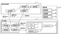
- FIG. 1 is a diagram illustrating an example of a functional configuration of a ventilation control device 1 according to the first embodiment.
- the ventilation control device 1 includes a storage device 11, a calculation device 12, a reception device 13, and a transmission device 14.
- the target air conditioning equipment includes a ventilation device 2 and an air conditioner 3.
- the air conditioner 3 has a plurality of air conditioners 3a to 3c. In addition, although the case where it has three air conditioners 3a-3c in FIG. 1 is illustrated, it is sufficient if it is two or more. Further, FIG. 1 shows only one ventilator 2, but it is not necessary to have one unit, and a plurality of units are generally installed in an office building or the like.
- a multi-air conditioner for buildings will be described as a representative example of the air conditioner 3.
- a building multi-air conditioner a plurality of indoor units are connected to one or a plurality of outdoor units by a refrigerant system.
- the refrigerant that is the heat medium is cooled or heated, and in the indoor unit, heat is exchanged between the cooled or heated refrigerant and the room air to perform air conditioning.
- a plurality of sets of outdoor units / indoor units connected by a refrigerant system as described above are generally installed according to the scale of the building / floor.
- each of the air conditioners 3a to 3c refers to a set of outdoor units and indoor units connected by the same refrigerant system.
- the number of air conditioners 3 refers to the number of refrigerant systems.
- the air conditioner 3 is not a multi air conditioner for buildings as described above, but may be a packaged air conditioner in which an outdoor unit and an indoor unit are connected one-to-one, which is used when the scale of a building / floor is small. . Further, it may be a central air-conditioning facility that has one or a plurality of heat source units and uses water, air, or the like as a heat medium, for example, for the entire building air conditioning of a large-scale building.
- the target may be a general house and the air conditioner 3 may be a room air conditioner. These are merely examples, and the type of the air conditioner 3 is not limited to the above. Further, the air conditioning target space is not limited to the above.
- Each of the plurality of air conditioners 3a to 3c is in charge of one air conditioning area.
- the areas handled by the plurality of air conditioners 3a to 3c are defined as zones Z1 to Z3, respectively.
- the area handled by the ventilator 2 is generally larger than the area handled by the individual air conditioners 3, so that such zones Z1 ⁇ Z3 is divided.
- a plurality of air conditioners 3 (refrigerant system) are installed in an area handled by the ventilator 2, and the areas handled by the individual air conditioners 3a to 3c are defined as “zones”. To do.
- FIG. 13 is a system configuration diagram in which one ventilation device 2 is installed and three air conditioners 3a to 3c (three refrigerant systems) are installed.
- three zones Z1 to Z3 are formed in accordance with the areas in charge of the three air conditioners 3a to 3c.
- FIG. 18 is a system configuration diagram in which two ventilation devices 2 and four air conditioners 3 (four refrigerant systems) are installed. In this example, it is divided into four zones according to the area in charge of the four air conditioners 3.
- FIG. 2 is a system configuration diagram in which the configuration of the ventilation device 2 is detailed.
- the ventilation device 2 includes a storage device 2a, a calculation device 2b, a reception device 2c, a transmission device 2d, a fan 2e, a valve 2f, a CO 2 sensor 2g, and a heat exchange unit 2h.
- FIG. 2 only lists general and main components as the components of the ventilation device 2, and it is not necessary to include all of these components, and components that are not illustrated may be included. Good.
- the storage device 2a is a device for storing information necessary for performing measurement control in the ventilation device 2, and is a memory or the like.
- the memory is only an example, and the type is not particularly limited as long as it is a device capable of storing data, such as a hard disk drive or an SD card.
- the computing device 2b is a device that computes a control command to the fan 2e, the valve 2f, etc., using data stored in the storage device 2a, and is a processor or the like.
- the receiving device 2c is a device that receives measurement data from devices such as the fan 2e and the valve 2f and sensors such as the CO 2 sensor 2g.
- the measurement data may include an operation state such as an operation mode of the device.
- the receiving device 2c also receives data from the transmitting device 14 of the ventilation control device 1.
- the transmission device 2d is a device that transmits a control command to the control target device to the fan 2e, the valve 2f, and the like. You may transmit the measurement instruction
- the means by which the receiving device 2c and the transmitting device 2d communicate with the ventilation control device 1 and each device / sensor is, for example, a dedicated network for a target air conditioning facility, a general-purpose network such as a LAN, and an individual device / sensor that is different from each other. They are dedicated lines or the like, and may be different communication means. Moreover, you may communicate by radio
- the means for communicating is not particularly limited with respect to the type of cable, protocol, etc., and communication means not listed above may be used. Further, the communication means used in the reception device 2c and the communication means used in the transmission device 2d may be the same or different. That is, a plurality of types of communication means may be combined.
- the fan 2e is a device for generating an air flow that takes air outside the building into the room and discharges the air outside the building.
- a fan for taking air outside the building into the room and a fan for discharging indoor air outside the building are installed separately.
- the valve 2f is a device for switching the air flow path. For example, when air outside a building is taken into a room, it is used to switch between a path that passes through the heat exchange unit 2h and a path that does not pass through.
- the CO 2 sensor 2g is a sensor that measures the indoor CO 2 concentration.
- the heat exchange unit 2h is a device for exchanging heat between air taken into the room from outside the building and air discharged from the room to outside the building.
- the ventilator 2 may be configured not to include the heat exchange unit 2h, and in this case, the air outside the building is directly taken into the room without heat exchange.
- the heat exchange in the heat exchange unit 2h may be total heat exchange or sensible heat exchange.
- the ventilator 2 has been described with respect to a configuration having two functions, a function of taking air into the room from the outside of the building and a function of discharging air from the room to the outside of the building. A configuration having only functions may be used.
- a device for the purpose of balancing the pressure inside and outside the building may be installed separately.
- the ventilation device 2 may operate independently of this separately installed device, or may operate in conjunction with it.
- the separately installed device may be a device that simply allows air to enter and exit, such as a ventilation port.
- FIG. 12 is a system configuration diagram of a modification of the first embodiment.
- the ventilation device 2 includes a temperature adjustment unit 2A and a humidity adjustment unit 2B in addition to the configuration of FIG.
- the temperature adjustment unit 2A includes a heat source device 2i, a heat exchanger 2j, and a heater 2k
- the humidity adjustment unit 2B includes a humidifier 2l and a dehumidifier 2m.
- the temperature adjusting unit 2A has a function of adjusting the temperature before supplying the air after passing through the heat exchange unit 2h or the air not passing through the room.
- the humidity adjusting unit 2B has a function of adjusting the humidity before supplying the air after passing through the heat exchange unit 2h or the air that has not passed through into the room.
- the heat source device 2i is a device that cools or heats a heat medium such as a refrigerant and water.
- the heat exchanger 2j is a device that exchanges heat between the air after passing through the heat exchange unit 2h or the air that has not passed through and the heat medium. The temperature-adjusted air after this heat exchange is supplied indoors.
- the heater 2k is a device that further heats the air before supplying it into the room.
- the humidifier 21 is a device that humidifies before supplying air into the room, and the dehumidifier 2m is a device that dehumidifies before supplying air into the room.
- FIG. 3 is an explanatory diagram of the flow of air flowing through the ventilation device 2.
- the heat exchange unit 2h is shown as a component.
- the air outside the building passes through the heat exchange unit 2h and is taken into the room.
- air that enters the ventilator 2 from outside the building is referred to as “outside air”, and air that is taken into the room is referred to as “air supply”.
- indoor air passes through the heat exchange unit 2h and is discharged outside the building.
- the air that enters the ventilation device 2 from the room is referred to as “circulation”, and the air that is discharged outside the building is referred to as “exhaust”.
- the heat exchange unit 2h heat exchange is performed between the outside air and the atmosphere, and the supply air whose temperature is adjusted or temperature and humidity is adjusted is supplied to the room.
- outside air may be directly taken into the room without passing through the heat exchange unit 2h. Whether or not to pass through the heat exchange unit 2h is normally switched by the valve 2f shown in FIG.
- the storage device 11 stores operation conditions, operation measurement data, models, load results, ventilation amounts, and control commands.
- the operating conditions stored in the storage device 11 are various conditions necessary for the processing of each unit in the arithmetic device 12.
- the various conditions include, for example, the number of ventilation devices 2, the number of air conditioners 3, information regarding the configuration of the air conditioning equipment such as connection relations, and the cycle in which the operation state of the ventilation device 2 is determined by the operation state determination unit 12e.
- the type and period of data transmitted and received between the reception device 13 and the transmission device 14 are also included.
- These pieces of information also include information on the areas handled by one or a plurality of ventilators 2 and a plurality of air conditioners 3 and the division of zones Z1 to Z3 based thereon.
- the operation measurement data stored in the storage device 11 are the operation measurement data of the ventilation device 2 and the operation measurement data of the air conditioner 3.
- the operation measurement data of the ventilator 2 includes, for example, the operation state such as strong / weak / stop, the operation mode indicating whether the heat exchange unit 2h is passed, the temperature, flow rate, humidity, CO 2 concentration measured in each part, Power etc.
- the operation measurement data of the air conditioner 3 includes, for example, a set value such as a set temperature, an operation mode such as cooling / heating / air blowing, a temperature, a flow rate, a humidity, and a CO 2 concentration measured in each part such as a room temperature and a refrigerant temperature. , Power etc.
- the above only lists typical operation measurement data, and it is not necessary to limit to these, and it is not necessary to include all of them.
- the models stored in the storage device 11 are a ventilation device model and an air conditioner model.
- the ventilator model is a model of the relationship between the ventilation amount and the power consumption as a characteristic of the ventilator 2.
- the air conditioner model is a model of the relationship between the amount of heat processed and power consumption as a characteristic of the air conditioner 3.
- the storage device 11 stores an air conditioner model for each of the individual air conditioners 3a to 3c. However, a common air conditioner model may be stored in the storage device 11 for air conditioners having the same characteristics.
- the storage device 11 stores a ventilation device model for each of the individual ventilation devices 2.
- a common ventilator model may be stored in the storage device 11 for the ventilator 2 having the same characteristics. Details of these models will be described later in the ventilation load calculation unit 12a, the air conditioning load calculation unit 12b, and the operation state determination unit 12e.
- the load results stored in the storage device 11 are the ventilation load calculated by the ventilation load calculation unit 12a, the air conditioning load calculated by the air conditioning load calculation unit 12b, and the thermal load calculated by the heat load calculation unit 12c.
- the ventilation load is stored for each ventilation device 2
- the air conditioning load is stored for each individual air conditioner 3a to 3c
- the thermal load is stored for each zone Z1 to Z3.
- the storage device 11 may store a ventilation load, an air conditioning load, and a heat load on the entire floor or the like.
- the ventilation volume and the control command stored in the storage device 11 are the ventilation volume determined by the operating state determination unit 12e and the control command determined by the control command conversion unit 12f, respectively.
- the storage device 11 may be configured to store data measured by various sensors not shown in the drawing, such as outside air temperature data.
- the computing device 12 includes a ventilation load calculation unit 12a, an air conditioning load calculation unit 12b, a thermal load calculation unit 12c, an operation state determination unit 12e, and a control command conversion unit 12f.
- the ventilation load calculation unit 12a calculates the ventilation load from the operation measurement data of the ventilation device 2 and the air conditioner 3 stored in the storage device 11 and the ventilation device model.
- the ventilation load is a load generated by ventilation, and the amount of heat processed by the air conditioners 3a to 3c changes by the amount of the ventilation load.
- a negative value is defined as a state in which heat is emitted from the room, for example, outside air cooling
- a positive value is defined as a state in which heat enters the room.
- the ventilation load is calculated for each ventilation device 2.
- Ventilation load is calculated by the following formula (1), for example. This calculation formula forms part of the ventilator model.
- Ventilation load ventilation volume x (supply air temperature-set temperature) x constant (1)
- the supply air temperature is the temperature of the air (supply air) supplied to the room by the ventilator 2 shown in FIG.
- the ventilation amount and supply air temperature of the above equation (1) are acquired from the operation measurement data of the ventilator 2, and the set temperature is acquired from the operation measurement data of the air conditioner 3.
- the constant is a fixed value determined from the specific heat of air, the density of air, and the like, and is stored in the storage device 11 as an operating condition.
- the set temperature acquisition targets are the air conditioners 3a to 3c included in the area in which the ventilator 2 is in charge.
- the set temperature is acquired from all the air conditioners 3a to 3c of the three refrigerant systems.
- the set temperature is set for each indoor unit 3y. Therefore, the six indoor units 3y shown in FIG. 13 are the acquisition targets of the set temperature.
- the set temperature of Formula (1) is calculated from these acquired set temperatures, the calculation method is not particularly limited. For example, it is good also as an average of all the acquired preset temperatures, and it is good also as the highest or lowest preset temperature.
- the ON / OFF state of the indoor unit 3y may be acquired together, and the set temperature of Expression (1) may be calculated using only the set temperature of the indoor unit 3y in the ON state.
- the ventilation volume may be calculated from the air volume or the rated air volume.
- the ventilator 2 needs to be provided with an air supply temperature sensor not explicitly shown in FIG.
- the ventilation device 2 does not include the supply air temperature sensor
- the supply air temperature sensor is installed independently of the ventilation device 2, and the reception device 13 acquires the measurement data. Or you may calculate ventilation load by following Formula (2), for example, without using supply air temperature.
- Ventilation load ventilation volume x (outside temperature-room temperature) x (1-heat exchange rate) x constant (2)
- the heat exchange rate is the heat exchange rate of the heat exchange unit 2h, and is stored in the storage device 11 as the operating condition.
- the heat exchange rate of equation (2) is zero.
- the room temperature of the formula (2) is acquired from the operation measurement data of the ventilator 2 when the ventilator 2 measures the ambient temperature shown in FIG.
- the ventilator 2 is not measuring the ambient temperature, it is acquired from the operation measurement data of the air conditioner 3. Since the air conditioner 3 normally measures the suction temperature of the indoor unit, this may be used as the room temperature.
- the suction temperature acquisition target is the air conditioners 3a to 3c included in the area in which the ventilation device 2 is in charge.
- the suction temperature acquisition target is the air conditioners 3a to 3c included in the area in which the ventilation device 2 is in charge.
- six indoor units are the acquisition targets of the suction temperature.
- the room temperature of Formula (2) is calculated from these acquired several suction temperatures, the calculation method is not specifically limited. For example, it may be the average of all acquired suction temperatures, or may be the highest or lowest suction temperature.
- the ON / OFF state of the indoor unit may be acquired together, and the suction temperature of the above equation may be calculated using only the suction temperature of the indoor unit in the ON state.
- the outside air temperature is acquired from the operation measurement data of the ventilator 2 when the ventilator 2 measures the temperature of the outside air shown in FIG.
- the ventilator 2 is not measuring the outside air temperature
- it is acquired from the operation measurement data of the air conditioner 3. Since the air conditioner 3 normally measures the outside air temperature with the outdoor unit 3x, this may be used.
- the acquisition target of the outside air temperature is an indoor unit included in the area handled by the ventilation device 2.
- the outside air temperature is acquired from all the air conditioners of the three refrigerant systems.
- the three outdoor units 3x described in FIG. 13 are the acquisition targets of the outside air temperature.
- the outside air temperature in the above equation is calculated from these acquired outside air temperatures, but the calculation method is not particularly limited. For example, the average of all acquired outside temperatures may be used, or the highest or lowest outside temperature may be used.
- an ambient temperature sensor a room temperature sensor, an outside temperature sensor, and the like may be installed as necessary, and the receiving device 13 may acquire measurement data of these sensors.
- the unit of ventilation load may set kW, for example, and consistency can be taken in the process of the ventilation control apparatus 1.
- this ventilation load may be stored in the storage device 11 and used.
- the ventilation load is calculated for each ventilation device 2.
- the air conditioner in charge of the air conditioner 3 and the area in charge of the air conditioner 3 are not considered to be the same. 3 is used.
- the entire floor may be integrated into one to calculate the ventilation load.
- the ventilation load of the entire floor may be calculated, or the ventilation load of the entire floor may be calculated using operation measurement data of any one ventilation device 2 arbitrarily selected.
- the entire floor is not necessarily combined into one, and may be combined into two, three, etc., for example.
- Various information on how to calculate the ventilation load described above is stored in the storage device 11 as operating conditions.
- the calculated result is stored in the storage device 11 as a ventilation load.
- Air conditioning load calculator 12b calculates the air conditioning load from the operation measurement data of the air conditioner 3 and the air conditioner model stored in the storage device 11.
- the air conditioning load is a load processed by the air conditioner 3.
- a minus value is defined as a state which requires heating
- a plus value is defined as a state which requires cooling.
- the compressor frequency and the outside air temperature are used as the following equation (3), and the compressor frequency is calculated as a quadratic expression and the outside air temperature is a primary expression.
- This calculation formula forms part of the air conditioner model.
- Air conditioning load a2 x frequency x frequency + a1 x frequency + b1 x outside air temperature + c0 (3)
- the coefficients a2, a1, b1, and c0 of the secondary equation and the linear equation are characteristic data of the air conditioner 3 that varies depending on the model of the air conditioner 3, and are included in the air conditioner model. These coefficients are determined based on experimental data, device design data, and the like. Normally, the coefficient value is different between cooling and heating.
- condensation temperature and evaporation temperature can be measured as the refrigerant temperature
- these may be used as calculation formulas.
- the calculation formula for calculating the air conditioning load actually processed from the power consumption is used. Also good.
- the calculation of the air conditioning load is not calculated using such an approximate expression, but the air conditioning load may be calculated based on an equation based on a physical model, or input from measurement data such as a neural network. You may make it calculate by the black box model which models an output relationship.
- the operation measurement data of the air conditioner 3 used for calculating the air conditioning load includes measurement by a sensor such as compressor frequency, outside air temperature, condensing temperature, evaporation temperature, power consumption, suction temperature, blowing temperature, refrigerant flow rate, etc.
- Operation data such as data, operation modes such as cooling / heating / air blowing, operation states such as start / stop, and setting data such as set temperature may be used.
- the unit of air-conditioning load is set to kW.
- the air conditioning load may be stored in the storage device 11 and used.
- each of the air conditioners 3a to 3c means each refrigerant system.
- the air conditioning loads of all the outdoor units 3x connected to this refrigerant system may be added. Good.
- the equipment configuration such as the connection relationship of the refrigerant system is not clear, for example, the entire floor may be integrated into one to calculate the air conditioning load.
- the air conditioning efficiency may be set to a different value depending on the value of other measurement data such as temperature. Further, the entire floor is not necessarily combined into one, and may be combined into two, three, etc., for example.
- the thermal load calculation unit 12c calculates the actually processed thermal load using the ventilation load calculated by the ventilation load calculation unit 12a and the air conditioning load calculated by the air conditioning load calculation unit 12b. Regarding the sign of the heat load, a negative value is defined as a state in which heat is emitted from the room, and a positive value is defined as a state in which heat enters the room (including the generation of heat in the room).
- the floor is divided into a plurality of zones Z1 to Z3 by the above-described method based on the information on the areas handled by each of the plurality of ventilation devices 2 and the plurality of air conditioners 3.
- the heat load is calculated for each zone Z1-Z3.
- one ventilator 2 and three air conditioners 3a to 3c are installed. In this case, as described above, it is divided into three zones according to the area in charge of the three air conditioners 3a to 3c.
- the heat load is calculated by the following equation (4). As described above, calculation is performed for each of the zones Z1 to Z3.
- Heat load Air conditioning load-Ventilation load (4)
- the ventilation load for each ventilation device 2 is calculated, but this must be distributed to each of the zones Z1 to Z3.
- the most basic method there is an equal split according to the number of zones included in the area targeted by the ventilator 2.
- the ventilation load in each of the zones Z1 to Z3 is 1/3 of the total ventilation load.
- the distribution may be performed accordingly.
- the air conditioning load calculation unit 12b calculates the air conditioning load for each of the zones Z1 to Z3 (for each of the air conditioners 3a to 3c).
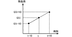
- FIG. 4 is an image diagram of this estimation method.
- the above equation (4a) is only an example, and may be a quadratic approximation as described above. Further, although the calculation of the heat load is performed in increments of 10 minutes, this is also an example, and there are no particular restrictions on the number of minutes, and it may be in increments of 1 minute or 30 minutes. Moreover, although the example which calculates
- the future heat load is estimated from the history of the heat load actually processed for the last few times.
- the future heat load may be estimated from the history of the heat load on another day.
- the thermal load 10 minutes ahead is estimated from the increasing / decreasing trend of the thermal load at the same time the previous day.
- the average increase trend / decrease trend may be used by using the heat load at the same time on weekdays for several days, and the increase / decrease trend of the heat load at the same time on the same day of the week before may be used. It may be used.
- it may be estimated by taking into consideration the outside air temperature, the amount of solar radiation, and the like.
- CO 2 concentration calculator Although not shown in the figure and not necessarily provided, a CO 2 concentration calculation unit will be described as a useful component.
- CO 2 concentration calculation unit based on the CO 2 concentration stored in the storage unit 11, estimates the CO 2 concentration in the chamber when operating the ventilator 2 in ventilation given.
- the ventilation amount is given by the operation state determination unit 12e.
- the CO 2 concentration calculation unit is not provided as a component of the ventilation control device 1 may be employed.
- the CO 2 concentration is calculated using, for example, the following relational expression (5).
- the current CO 2 concentration is stored in the storage device 11.
- CO 2 concentration current CO 2 concentration + CO 2 generation amount from human body-CO 2 removal amount by ventilation-CO 2 decrease amount by interstitial wind etc ... (5)
- the amount of CO 2 generated from the human body is a product of the amount of CO 2 generated per person set based on literature data and the number of people in the room.
- the number of people in the room may be preliminarily stored in the storage device 11 as a daily number of people pattern, or may be estimated by learning from operation measurement data of the ventilation device 2 and the air conditioner 3. Alternatively, the information may be used if an entrance / exit management system is introduced.
- CO 2 removals by ventilation, ventilation, current CO 2 concentration can be calculated from the outside air CO 2 concentration and the like.
- the CO 2 concentration in the outside air may be set at, for example, a general value of 350 ppm, but is not limited to this value. If a sensor for measuring the CO 2 concentration of outside air not shown in the figure is provided, the value may be used. If there is other information necessary for calculating the CO 2 removal amount, it is stored in advance in the storage device 11 or estimated by learning or the like from the operation measurement data of the ventilation device 2 and the air conditioner 3. Alternatively, the CO 2 reduction amount per 1 m 3 of ventilation may be stored in the storage device 11 as a fixed value, and a value obtained by multiplying this value and the ventilation rate may be used as the CO 2 removal amount.
- the amount of CO 2 reduction due to a draft or the like may be stored in the storage device 11 in advance, or may be estimated by learning from operation measurement data of the ventilation device 2 and the air conditioner 3. Further, the value may be a fixed value that does not change over time, or may be a pattern that changes over time.
- the present invention is not limited to this.
- the term of CO 2 reduction amount due to the draft or the like may be deleted from the above formula.
- it may be calculated in more detail based on an equation based on a physical model for obtaining a change in CO 2 concentration over time, or may be estimated by learning from operation measurement data of the ventilator 2 and the air conditioner 3. Also good.
- the operating state determination unit 12e determines the ventilation amount of each ventilation device 2 using the thermal load calculated by the thermal load calculation unit 12c, the ventilation device model and the air conditioner model stored in the storage device 11. In the determination of the ventilation amount, the total power consumption of the plurality of ventilators 2 and the plurality of air conditioners 3 is determined so as to be relatively smaller than the case where the other ventilation amounts are used. Desirably, the power consumption is determined to be minimum.
- the ventilator model is a model for calculating the power consumption with respect to the ventilation amount. For example, as shown in the following equation (6), there are a primary equation, a quadratic equation,.
- Ventilation device 2 power consumption a0 + a1 ⁇ (ventilation amount) + a2 ⁇ (ventilation amount ⁇ 2) + ... + an ⁇ (ventilation amount ⁇ n) (6)
- the air conditioner model is a model for calculating power consumption with respect to the amount of heat processed. For example, as shown in the following equation (7), a linear expression, a quadratic equation,. is there.
- Air conditioner power consumption b0 + b1 x (processing heat) + b2 x (processing heat ⁇ 2) + ... + bn x (processing heat ⁇ n) (7)
- the ventilator model may be a cubic equation
- the air conditioner model may be a quadratic equation, or the like.
- the coefficients a0, a1, ..., b0, b1, ... are stored in the storage device 11 as part of the model.
- These calculation formulas are examples, and may be calculation formulas that take into account, for example, the outside air temperature.
- the power consumption of the air conditioner 3 may be a two-stage calculation method in which the power consumption of the air conditioner 3 is a quadratic expression related to the compressor frequency, and the frequency given to this expression is calculated from the amount of heat processed.
- the ventilator model and the air conditioner model may include a data table, and the power consumption may be obtained based on the data table.
- the air conditioner model includes a table that stores the efficiency of the air conditioner 3 with respect to the outside air temperature in increments of 10 ° C. That is, the storage device 11 has an air conditioner such as C1 when the outside air temperature is T1, C2 when the outside air temperature is T2, C3 when the outside air temperature is T3, and C3 when the outside air temperature is T3.
- the outside air temperature when determining the ventilation amount is T1
- “power consumption processing heat amount / C1”.
- the ventilator model is composed of a table storing the power consumption of the ventilator 2 for each ventilation amount. That is, the storage device 11 stores, as a ventilator model, a table in which the power consumption is P1 when the ventilation is strong, the power consumption is P2 when the ventilation is low, and the power consumption is P3 when the ventilation is weak. If continuous ventilation can be commanded, the rated output ratio may be 100%, 80%, 50%, etc., not strong, medium, or weak. In the case of intermediate ventilation, data may be interpolated.
- the amount of heat given to the air conditioner model can be obtained from the ventilation volume.
- the ventilation load with respect to the ventilation amount can be calculated using the ventilation load calculation unit 12a.
- the air conditioning load that is, the amount of heat processed by the air conditioner 3
- the data necessary for the calculation of the ventilation load calculation unit 12a for example, various conditions such as the supply air temperature, the set temperature, whether or not to pass through the heat exchange unit 2h, the measurement data at the time of executing this calculation Use it.
- the operating state determination unit 12e performs the following processing for each of the plurality of ventilation devices 2. Since one ventilator 2 is responsible for a plurality of zones, the power consumption is evaluated collectively for these responsible zones.
- the operating state determination unit 12e determines a combination of the operating states of the air conditioner 3 and the ventilator 2 as the air conditioning equipment that processes the heat load. As a combination of the operating states of the air conditioner and the ventilator 2, it is determined whether a combination other than the current operating state is possible, and if possible, a plurality of operating states are selected as candidates, and the power consumption is calculated for those operating states. In comparison, the state in which the power consumption is reduced is determined as the operating state of the ventilator 2.
- the operation state of the ventilation device 2 when there are no plurality of candidates as the operation state of the ventilation device 2, it is not necessary to determine the operation state based on the power consumption. For example, when the air conditioner 3 is in cooling operation and the outside air temperature is equal to or higher than the target set temperature of the air conditioning target area, increasing the ventilation volume increases both the power consumption of the air conditioner 3 and the ventilator 2, so that ventilation is generally performed.
- the operation state of the apparatus 2 may be set to the minimum necessary ventilation amount, and there are no plurality of candidates as the operation state. In such a case, the state in which the necessary minimum ventilation volume is obtained is determined as the operating state of the ventilator 2. Usually, this is the minimum ventilation required to maintain the CO 2 concentration described below below the reference value.
- the power consumption can be reduced by changing the operation state of the ventilator 2 by the outside air cooling. Therefore, a plurality of possible states as the operation state of the ventilator 2 are selected as candidates, and the power consumption of the ventilator 2 is calculated.
- the ventilation device 2 it is necessary to distribute the entire ventilation load by the ventilation device 2 to the ventilation loads for each of the zones Z1 to Z3.
- the ventilation load in each of the zones Z1 to Z3 is 1/3 of the total ventilation load.
- the distribution may be performed accordingly. For example, in FIG. 13, when it is known that the ratio of the air supply amount to the zones Z1 to Z3 is 3: 2: 1, the zone Z1 is 3/6, the zone Z2 is 2/6, 1/6 ventilation is distributed to zone Z3.
- each of the zones Z1 to Z3 may be known, distribution may be performed accordingly.
- the ratio of the floor area to the zones Z1 to Z3 is 3: 2: 1
- the zone Z1 is 3/6
- the zone Z2 is 2/6
- the CO 2 concentration calculation unit determines a minimum amount of ventilation required for the CO 2 concentration is maintained at less than the reference value.
- this ventilation volume is described as the minimum ventilation volume.
- the power consumption at this time is calculated
- the reference value of the CO 2 concentration may be, for example, 1000 ppm, which is a legal standard. However, it is not necessary to limit to 1000 ppm, and this reference value is stored in the storage device 11 as an operating condition.
- the ventilation volume may be determined using a table in which the CO 2 concentration and the necessary ventilation volume are associated without using the CO 2 concentration calculation unit.
- the table is such that when the CO 2 concentration is 400 ppm or less, it is stopped, 600 ppm or less is weak, 800 ppm or less is medium, and 800 ppm or more is strong.
- the minimum ventilation volume may be determined by linearly interpolating the table value according to the intermediate CO 2 concentration.
- the ventilation control apparatus 1 need not comprise the CO 2 concentration calculation unit.
- the minimum ventilation amount required for processing the operating state that the ventilation device 2 can take is determined. For example, in the above example, when the CO 2 concentration is 600 ppm or less, the operation state of the ventilator 2 is weak and sufficient, and therefore, a plurality of operation states of weak, medium, and strong, which are more than weak, can be selected.
- the ventilation volume is changed variously, and the ventilation volume when the result of calculating the sum of the power consumption of the ventilation device 2 and the power consumption of the air conditioner 3 at each ventilation volume is the smallest is stored in the storage device 11.
- the ventilation volume may be sequentially increased from the minimum ventilation volume, or may be increased / decreased in a random or stochastic range. However, when decreasing, do not become smaller than the minimum ventilation.
- the range of increase / decrease in the ventilation volume is determined according to the specifications of the ventilation device 2 such as, for example, only strong / medium / weak / stopping is possible.
- the ventilation volume can take a continuous value, it may be a fixed increase / decrease width, or the width may be changed every time.
- the final ventilation amount may be determined by changing the ventilation amount more finely in the vicinity of the ventilation amount once obtained in this way. If general numerical analysis methods that solve optimization problems such as linear programming and quadratic programming can be used according to the configuration of the ventilator model and air conditioner model, these are used. May be.
- the ventilation amount of the ventilation device 2 and the processing heat amount of the air conditioner 3 determined thereby may consider the maximum / minimum ventilation amount of the ventilation device 2 and the maximum / minimum processing heat amount of the air conditioner 3. For example, if the maximum processing heat amount of the air conditioner 3 is Q1 and the minimum processing heat amount is Q2, the processing heat amount of the air conditioner 3 calculated in the process of determining the ventilation amount does not allow a ventilation amount exceeding Q1, Q2 When it is less, the heat of treatment is set to zero. Along with this, necessary parts are recalculated.
- the ventilation amount it may be determined whether to switch the heat exchange unit 2h or not. That is, in the evaluation of the power consumption for each ventilation amount, the power consumption when passing through the heat exchange unit 2h and the power consumption when not passing through the heat exchange unit 2h are calculated, and the one with lower power consumption is selected. Specifically, the difference in ventilation load that is affected by whether or not it passes through the heat exchange unit 2h is considered in the calculation of the power consumption of the air conditioner 3 by the air conditioner model. Thereby, the ventilation volume which passes the heat exchange unit 2h and the ventilation volume which does not pass the heat exchange unit 2h are determined.
- the ventilation amount may be determined in consideration of this, and whether the heat exchange unit 2h is allowed to pass may be determined. In other words, if it is known that the desired operation cannot be obtained even if the ventilation device 2 receives, the ventilation amount is determined so as not to be such a control command.
- FIG. 14 is a graph showing the relationship between the heat load, the ventilation load, and the air conditioning load for each zone in the air conditioning facility of FIG.
- FIG. 14 illustrates the case where the outside air temperature is lower than the set temperature and the outside air cooling is performed, that is, the state when the ventilation load is a negative value.
- the case where the outside air cooling with a great effect is performed unless there is particular notice is demonstrated.
- the heat load is mainly intrusion heat from outside the building and internal heat generation.
- the zone Z1 faces the south surface, the influence of solar radiation is large, and since the number of people and devices is large, internal heat generation is large and the heat load is large.
- the zone Z3 faces the north surface, the influence of solar radiation is small, and since the number of people and devices is small, the internal heat generation is small and the heat load is small. Thus, the heat load is usually non-uniform throughout the air-conditioning target area.
- the ventilation load takes a negative value due to the outside air cooling, and the air conditioning load is reduced. Although the magnitude of the heat load varies depending on the zones Z1 to Z3, the ventilation load is the same in each of the zones Z1 to Z3 since there is one ventilation device 2.
- FIG. 15 is a graph showing the relationship between the power consumption of the air conditioner and the power consumption of the ventilation device 2 with respect to the ventilation amount.
- the power consumption of the ventilator 2 increases as the ventilation amount increases.
- the amount of ventilation increases and the power consumption of the air conditioners 3a to 3c decreases.
- the power consumption of the air conditioners 3a to 3c increases with the increase of the ventilation amount. Therefore, the ventilation amount should be as small as possible, and the minimum depending on the CO 2 concentration restriction. Ventilation rate should be sufficient.
- FIG. 16 is a graph showing the relationship between the amount of heat processed and the efficiency (COP) in the air conditioner. As shown in FIG. 16, even in the same air conditioner, the efficiency of the air conditioner varies depending on the amount of heat processed. Accordingly, the slope of the power consumption graph of the air conditioner in FIG. 15 varies depending on the magnitude of the heat load, and the change amount of the air conditioning load with respect to the change amount of the same ventilation load in each of the zones Z1 to Z3 having different heat loads. Will be different.
- FIG. 17 is a graph showing the relationship between the ventilation volume and the total power consumption of the ventilation devices 2 and the air conditioners 3a to 3c in all zones Z1 to Z3.
- the total power consumption of the ventilation device 2 and the air conditioners 3a to 3c in all the zones Z1 to Z3 has a complicated relationship. Furthermore, this relationship is further complicated when the models, capacities, etc. of the plurality of air conditioners 3a to 3c are different. In order to cope with this, the relationship between the air conditioning load and the power consumption is modeled as an air conditioner model for each of the air conditioners 3a to 3c.
- the operation state determination unit 12e changes the ventilation amount in all zones Z1 to Z3 by the same amount, and as a result, the air conditioners 3a to 3c change when the ventilation load changes in all zones Z1 to Z3.
- the power consumption and the power consumption of the ventilation device 2 are calculated.
- the ventilation volume may be different for each of the zones Z1 to Z3 depending on the equipment design or operation conditions. For example, a case where a certain amount of ventilation is provided between the zones is assumed. In this case, the ventilation may be distributed to each of the zones Z1 to Z3 so as to satisfy this condition.
- the operation state determination unit 12e stores the ventilation amount when the result of calculating the sum of the power consumption of the ventilation device 2 and the power consumption of the air conditioners 3a to 3c for each ventilation amount is the smallest in the storage device 11.
- Control command converter 12f The control command conversion unit 12 f converts the ventilation amount determined by the operation state determination unit 12 e and stored in the storage device 11 into a control command that actually gives a command to the ventilation device 2.
- the control command format for the ventilator 2 is strong / medium / weak / stop for the ventilator 2
- the memorized ventilation volume is selected from the corresponding command strong / medium / weak / stop.
- the storage device 11 is stored in the storage device 11 as a control command.
- the above strong / medium / weak / stop is an example, and the format of the control command is not limited to this. Since the control command that can be received by the ventilator 2 is different for each model, the control command is generated according to the model. Information necessary for this is stored in the storage device 11 as operating conditions. Further, when the ventilation amount determined by the operation state determination unit 12e can be commanded to the ventilation device 2 as it is, there is no need to convert it, and the ventilation amount stored in the storage device 11 and the control command are the same.
- the receiving device 13 communicates with the ventilator 2 and the air conditioner 3, receives data from the ventilator 2 and the air conditioner 3, and stores the received data in the storage device 11.
- the transmission device 14 communicates with the ventilator 2 and the air conditioner 3, reads out the control command stored in the storage device 11, and transmits the control command to the ventilator 2 and the air conditioner 3.
- Means for the reception device 13 and the transmission device 14 to communicate with the ventilation device 2 and the air conditioner 3 is, for example, a dedicated network for the target air conditioning facility, a general-purpose network such as a LAN, an air conditioning facility (the ventilation device 2, the air conditioner 3). ), Different individual dedicated lines, etc., and different communication means may be used. Moreover, you may communicate by radio
- the means for communicating in this way is not particularly limited with respect to the type of cable, protocol, etc., and communication means not listed above may be used. Further, the communication means used in the reception device 13 and the communication means used in the transmission device 14 may be different. That is, a plurality of types of communication means may be combined.
- FIG. 11 is a flowchart showing a process flow of the ventilation control device 1 according to the first embodiment.
- This processing flow is executed at a predetermined time period such as a 10-minute period.
- the 10 minute period is an example, and may be a 1 minute period, a 30 minute period, or the like.
- This time period is stored in the storage device 11 as an operation condition.
- the processing flow is as follows. The detailed execution contents in each step are as described in the function of each part of the arithmetic unit 12.
- step ST1 the operating conditions are read from the storage device 11.
- step ST ⁇ b> 2 operation measurement data of the ventilation device 2 and the air conditioner 3 is read from the storage device 11.
- the ventilation load is calculated based on the operation conditions and the operation measurement data.
- step ST4 the air conditioning load is calculated based on the operation conditions and the operation measurement data.
- step ST5 the heat load is calculated based on the operating conditions, the ventilation load, and the air conditioning load.
- step ST6 the ventilation volume is calculated based on the operating conditions and the heat load.
- step ST7 the operating conditions and the ventilation volume are converted into control commands.
- step ST8 a control command is transmitted to the ventilator 2.
- the operation measurement data of the ventilation device 2 and the air conditioner 3 may be received and written to the storage device 11 at a predetermined cycle different from the above steps.
- data that needs immediacy such as an abnormality notification and an operation signal by the user may be received at a timing unrelated to a predetermined cycle.
- the air conditioning load and the ventilation load are calculated using the operation measurement data of the ventilation device 2 and the air conditioner 3, and the actual heat load is calculated based on this. .
- the ventilation apparatus model showing the relationship between ventilation volume and power consumption, and the air conditioner model showing the relationship between process heat quantity and power consumption are provided.
- the heat load is calculated for each zone, and the air conditioner model calculates the power consumption of each air conditioner in consideration of the change in power consumption with respect to the change in ventilation amount, which varies depending on the heat load.
- FIG. FIG. 5 is a functional configuration diagram of the ventilation control device 1 according to the second embodiment.
- FIG. 6 is a system configuration diagram in which the configuration of the ventilation device 2 is detailed.
- the ventilation device 2 does not include the CO 2 sensor 2g, but instead has an independent CO 2 sensor 4. Further, since the CO 2 concentration data is not included in the operation measurement data of the ventilation device 2 stored in the storage device 11, the data measured by the CO 2 sensor 4 is received by the reception device 13, and the CO 2 concentration is stored in the storage device 11. Stored as data.
- FIG. 7 is a functional configuration diagram of the ventilation control device 1 according to the third embodiment.
- FIG. 8 is a system configuration diagram in which the configuration of the ventilation device 2 is detailed.
- the ventilation control device 1 is incorporated as a part of the ventilation device 2.
- the storage device 11, the calculation device 12, the reception device 13, and the transmission device 14 of the ventilation control device 1 are the storage device 2a, the calculation device 2b, and the reception device that the ventilation device 2 described in the first embodiment includes. 2c and the transmitter 2d.
- the device / sensor 2x shown in FIG. 7 collectively displays the fan 2e, the valve 2f, and the heat exchange unit 2h.
- FIG. 9 is another functional configuration diagram of the ventilation control device 1 according to the third embodiment.
- FIG. 10 is a system configuration diagram in which the configuration of the ventilation device 2 is detailed.
- the ventilator 2 does not include the CO 2 sensor 2g but instead has an independent CO 2 sensor 4. Further, since the CO 2 concentration data is not included in the operation measurement data of the ventilation device 2 stored in the storage device 11, the data measured by the CO 2 sensor 4 is received by the reception device 13, and the CO 2 concentration is stored in the storage device 11. Stored as data.
- the device / sensor 2x shown in FIG. 9 collectively displays the fan 2e, the valve 2f, and the heat exchange unit 2h.
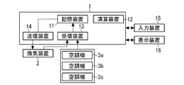
- FIG. 19 is a configuration diagram of the ventilation control device 1 according to Embodiment 4 of the present invention
- FIG. 20 is a schematic diagram illustrating an installation example of the air conditioning equipment of FIG.
- the difference from the first embodiment is that the input device 15 and the display device 16 are provided.
- symbol is attached
- the input device 15 is a device for inputting operating conditions necessary for the operation of the air conditioning equipment, model parameters, and the like.
- the input device 15 is, for example, a keyboard, a mouse, a touch panel, or the like, but is not limited thereto.
- the display device 16 is a device for displaying operation conditions, operation measurement data, and the like stored in the storage device 11.
- the display device 16 is, for example, a display, but is not limited thereto.
- the building owner, facility manager, resident, etc. input various information using the input device 15.
- the input information is stored in the storage device 11.
- the following information is input from the input device 15.
- the ventilation target area VZ is information about the position of the ventilation entrance / exit in the floor.
- the air-conditioning target area (zones Z1 to Z3) is information on the position of a plurality of indoor units 3y connected to each outdoor unit 3x on the floor in the case of a building multi-air conditioner.
- the information is such that the positional relationship between the ventilation target area VZ of each ventilation device 2 and the air conditioning target areas (zones Z1 to Z3) of the air conditioners 3a to 3c can be specified.
- Numerical data such as coordinates in the floor may be used, or an area selection on the drawing may be used, but the present invention is not limited to these.
- the equipment characteristic of the ventilator 2 is information on the ventilator model described in the first embodiment. For example, it is data such as a parameter set in a relational expression of ventilation volume and power consumption or a characteristic table.
- the device characteristics of the air conditioner are information on the air conditioner model described in the first embodiment. For example, the relational expression between the air conditioning load and the power consumption or data such as parameters set in the characteristic table.
- the displayed information is information stored in the storage device 11.
- the display content may be selected and displayed according to an input from the input device 15, for example, keyboard input, mouse selection, or the like.
- the display device 16 displays the following information.
- Information input by input device 15 (2) Operation measurement data of ventilation device 2 and air conditioners 3a to 3c (3) Ventilation load for each ventilation device 2, air conditioning load for each air conditioners 3a to 3c, zones Z1 to Heat load for each Z3 (4) Power consumption for each zone Z1 to Z3, total power consumption, and breakdown of the power consumption of the ventilator 2 and the power consumption of the air conditioners 3a to 3c (5) Ventilation target of each ventilator 2 Relationship between the area VZ and the air-conditioning target areas (zones Z1 to Z3) of the air conditioners 3a to 3c.
- the above (3) is a result calculated by the method described in the first embodiment using the operation measurement data.
- measurement data other than the operation measurement data of the ventilation device 2 and the air conditioners 3a to 3c for example, data measured by various sensors such as power consumption and power consumption may be displayed.
- power consumption either or both of the power estimated when determining the ventilation amount and the actually measured power measured by the sensor are displayed.
- the display methods of (2), (3), and (4) include, but are not limited to, a trend graph display as time series data, a digital value at a designated time, and the like.
- FIG. 21A is a schematic diagram showing an example of the heat load for each zone displayed on the display device 16 of FIG.
- FIG. 21B is a schematic diagram illustrating an example of power consumption with respect to the ventilation amount for each zone displayed on the display device 16 of FIG. 19.
- FIG. 21C is a schematic diagram illustrating an example of the power consumption of the entire air conditioning facility with respect to the ventilation amount displayed on the display device 16 of FIG. 19, and
- FIG. It is a schematic diagram showing an example of ventilation power and air conditioning power of the air conditioners 3a to 3c.
- the items (3) and (4) are displayed as shown in FIGS. 21A to 21D. These data may be displayed in association with the corresponding area / zone together with the floor drawing (for example, FIG. 20).
- the display method of (5) for example, as shown in FIG. 20, display is made so that the mutual positional relationship between the ventilation target area VZ and the air conditioning target area can be understood in the floor drawing or the like.
- each data of (3) and (4) may display the progress of the search while changing the ventilation volume in various ways when determining the ventilation volume.
- the relationship between the ventilation amount and the power consumption used for determining the ventilation amount as shown in FIGS. 15 and 17 may be displayed together.
- the above display method is an example of a typical display method, and is not necessarily limited to this. Since other functional configurations and operations are the same as those of the first embodiment, description thereof is omitted.
- FIG. 22 is a configuration diagram showing a modification of the ventilation control device 1 according to Embodiment 4 of the present invention.
- the input device 15 and the display device 16 exist outside the ventilation control device 1.
- the ventilation control device 1 is connected to an external device such as a PC, a server, a tablet terminal, or a smart phone via a network such as a LAN, and performs input and display on the external device.
- the ventilation control device 1 exchanges information between the input device 15 and the display device 16 of the external device by the reception device 13 and the transmission device 14.
- external devices are not limited to those listed above.
- FIG. 23 is a configuration diagram illustrating a modification of the ventilation control device 1 according to the fourth embodiment.
- the same parts as those in the first embodiment are denoted by the same reference numerals and the description thereof is omitted, and only functions and operations different from those in the first embodiment will be described below.
- the ventilation control device 1 is incorporated as a part of the ventilation device 2.
- FIG. 24 is another configuration diagram of the ventilation control device 1 according to the fourth embodiment.
- the same parts as those in the first embodiment are denoted by the same reference numerals and the description thereof is omitted, and only functions and operations different from those in the first embodiment will be described below.
- the ventilation control device 1 of FIG. 24 is incorporated as a part of the ventilation device 2, and the input device 15 and the display device 16 exist outside the ventilation control device 1.
- the present invention is useful for controlling a ventilation device.
Abstract
換気制御装置は、空調設備の運転計測データと、換気装置の換気量と消費電力の関係を表す換気装置モデルと、空調機の処理熱量と消費電力の関係を表す空調機モデルとを記憶する記憶装置と、換気装置の運転状態を決定する演算装置と、を備え、演算装置が、換気負荷計算部と、空調負荷計算部と、換気負荷と空調負荷とから熱負荷を計算する熱負荷計算部と、空調設備の運転状態の中から、空調設備の消費電力が相対的に小さくなるように換気装置の運転状態を決定する運転状態決定部と、を備える。 上記により、実際のゾーン毎の熱負荷に対して、換気装置と空調機の合計の消費電力を削減するような換気量を適切に決定することができ、省エネ性を向上することができる。
Description
この発明は、換気制御装置および換気制御方法に関するものである。
従来から、室内環境を快適に保つために建物外の空気を室内に取り入れる換気装置と、このような換気装置を制御するための換気制御装置が、ビル等の建物に設置されている。そのような換気制御装置では、例えば、外気温と室内の温度とが計測され、それらの計測値と空調機の設定温度とに応じて、外気が室内に供給される(例えば、特許文献1)。また、そのような換気制御装置では、例えば、室内の温度と快適温度域の中間温度とを比較して、外気が室内に供給される(例えば、特許文献2)。また、そのような換気制御装置では、例えば、外気温と室内の温度とを比較して、室内に供給される外気の量、つまり換気量が決定される(例えば、特許文献3)。また、そのような換気制御装置では、例えば、室内のCO2濃度が計測され、その計測値が基準値以下になるように、外気が室内に供給される(例えば、特許文献4)。特許文献1から3に開示された換気制御装置は、省エネ性を向上させることを目的としたものであり、特許文献4に開示された換気制御装置は、必要な量の外気を確実に取り込むことを目的としたものである。
特許文献1から3に開示されている従来の換気制御装置では、建物外の外気温度と室内温度から換気装置の運転状態を決定している。しかし、換気により発生する負荷(換気負荷)は空調機が処理する負荷(空調負荷)に影響を与え、さらには換気装置と空調機の消費電力は換気装置の運転状態によって変化するため、換気装置と空調機を合わせた空調設備全体での省エネ化を考えた場合、外気温度と室内温度だけから適切な換気量を決定することは困難である。また、複数台の空調機が設置されているシステム構成において、各空調機が担当するゾーン間の熱負荷のばらつきを考慮して換気量を決定する技術については開示されていない。このため、従来の技術では、省エネ性が不十分であるという問題点があった。
また、特許文献4に開示されている従来の換気制御装置では、外気冷房に着目した換気の促進の視点が考慮されていない。空調設備の省エネ化を図りつつCO2濃度を基準値以下にするためには、換気が抑制される必要がある。一方、空調設備の省エネ化を図るべく外気冷房を行うためには、換気が促進される必要がある。このため、従来の技術では、省エネ性が不十分であるという問題点があった。
本発明は、上記のような課題を背景としてなされたものであり、空調設備全体としての省エネ性を向上させる換気制御装置および換気制御方法を得るものである。
本発明の換気制御装置は、換気装置と、前記換気装置による換気対象エリアをゾーン毎に空調する複数台の空調機とを備えた空調設備の前記換気装置の運転状態を決定する換気制御装置であって、前記空調設備の運転計測データと、前記換気装置の換気量と消費電力の関係を表す換気装置モデルと、前記空調機の処理熱量と消費電力の関係を表す空調機モデルとを記憶する記憶装置と、前記換気装置の運転状態を決定する演算装置と、を備え、前記演算装置が、前記空調設備の運転計測データから前記換気装置により発生した換気負荷をゾーン毎に計算する換気負荷計算部と、前記空調設備の運転計測データから前記空調機が処理した空調負荷をゾーン毎に計算する空調負荷計算部と、前記換気負荷と前記空調負荷とから熱負荷をゾーン毎に計算する熱負荷計算部と、前記熱負荷を処理する前記空調設備の運転状態の中から、前記空調設備の消費電力が相対的に小さくなるように前記換気装置の運転状態を決定する運転状態決定部と、を有し、前記運転状態決定部は、前記熱負荷計算部において計算されたゾーン間の前記熱負荷のばらつきと、前記記憶装置に記憶された空調機モデルとに基づいて、前記換気装置の運転状態を決定するものであることを特徴とする。
また、本発明の換気制御方法は、換気装置と、前記換気装置による換気対象エリアをゾーン毎に空調する複数台の空調機とを備えた空調設備の前記換気装置の運転状態を決定する換気制御方法であって、前記空調設備の運転計測データを記憶し、前記空調設備の運転計測データから前記換気装置により発生した換気負荷をゾーン毎に計算し、前記空調設備の運転計測データから前記空調機が処理した空調負荷をゾーン毎に計算し、前記換気負荷と前記空調負荷とから熱負荷をゾーン毎に計算し、前記熱負荷計算部において計算されたゾーン間の前記熱負荷のばらつきと、前記記憶装置に記憶された空調機モデルとに基づいて、前記熱負荷を処理する前記空調設備の運転状態の中から、前記空調設備の消費電力が相対的に小さくなるように前記換気装置の運転状態を決定することを特徴とする。
本発明の換気制御装置および換気制御方法によれば、換気装置と空調機の運転計測データを用いてゾーン毎の換気負荷と空調負荷を計算し、これを基にゾーン毎の熱負荷を計算する。また、換気量と消費電力の関係を表す換気装置モデルと、空調機の処理熱量と消費電力の関係を表す空調機モデルとを備えている。これにより、実際のゾーン毎の熱負荷に対して、換気装置と空調機の合計の消費電力を削減するような換気量を適切に決定することができ、省エネ性を向上することができる、という効果がある。
実施の形態1.
図1は、実施の形態1に係る換気制御装置1の機能構成の一例を示す図である。図1に示すように、換気制御装置1は、記憶装置11、演算装置12、受信装置13、送信装置14を備える。また、対象とする空調設備は、換気装置2、空調機3を備える。空調機3は、複数台の空調機3a~3cを有する。なお、図1において3台の空調機3a~3cを有する場合について例示しているが、2台以上であればよい。また、図1には、換気装置2は1つしか示していないが、1台である必要はなく、オフィスビルなどでは一般に複数台が設置される。
図1は、実施の形態1に係る換気制御装置1の機能構成の一例を示す図である。図1に示すように、換気制御装置1は、記憶装置11、演算装置12、受信装置13、送信装置14を備える。また、対象とする空調設備は、換気装置2、空調機3を備える。空調機3は、複数台の空調機3a~3cを有する。なお、図1において3台の空調機3a~3cを有する場合について例示しているが、2台以上であればよい。また、図1には、換気装置2は1つしか示していないが、1台である必要はなく、オフィスビルなどでは一般に複数台が設置される。
本発明では、空調機3の代表例として、ビル用マルチエアコンを対象として説明する。ビル用マルチエアコンでは、1台または複数台の室外機に複数台の室内機が、冷媒系統で接続される。室外機において、熱媒体である冷媒が冷却または加熱され、室内機において、この冷却または加熱された冷媒と室内空気との間で熱交換し、空調を行う。例えばオフィスビルでは、上記のように冷媒系統で接続された室外機・室内機のセットが、建物・フロアの規模に応じて複数セット設置されるのが一般的である。以下では、個々の空調機3a~3cは、それぞれ、同一の冷媒系統で接続された室外機及び室内機のセットのことを指すものとする。また、特に断りのない限り、空調機3の台数とは冷媒系統の数を指すものとする。
ただし、空調機3は、上述のようにビル用マルチエアコンではなく、建物・フロアの規模が小さい場合に用いられる、室外機と室内機が1対1で接続されるパッケージエアコンであってもよい。また、1台または複数台の熱源機を持ち、熱媒体として水、空気等を用いて、例えば大規模ビルの全館空調に用いられるセントラル空調設備であってもよい。また、対象が一般住宅、空調機3がルームエアコンであってもよい。これらは一例であって、空調機3の種類は、上記に限定しない。また、空調対象空間も上記に限定しない。
(ゾーンの説明)
複数台の空調機3a~3cはそれぞれ1つ空調エリアを担当している。ここで、複数台の空調機3a~3cが担当する各エリアをそれぞれゾーンZ1~Z3として定義する。ビル用マルチエアコンが設置されているようなオフィスビルでは、換気装置2が担当するエリアは、個々の空調機3が担当するエリアよりも大きいのが一般的であるため、このようなゾーンZ1~Z3の分割が行われる。すなわち、空調設備は、換気装置2が担当するエリアに、複数台の空調機3(冷媒系統)が設置されるものであり、個々の空調機3a~3cが担当するエリアを「ゾーン」として定義する。
複数台の空調機3a~3cはそれぞれ1つ空調エリアを担当している。ここで、複数台の空調機3a~3cが担当する各エリアをそれぞれゾーンZ1~Z3として定義する。ビル用マルチエアコンが設置されているようなオフィスビルでは、換気装置2が担当するエリアは、個々の空調機3が担当するエリアよりも大きいのが一般的であるため、このようなゾーンZ1~Z3の分割が行われる。すなわち、空調設備は、換気装置2が担当するエリアに、複数台の空調機3(冷媒系統)が設置されるものであり、個々の空調機3a~3cが担当するエリアを「ゾーン」として定義する。
図13は、1台の換気装置2が設置され、3台の空調機3a~3c(3冷媒系統)が設置されているシステム構成図である。図13において、3台の空調機3a~3cの担当エリアに応じて3つのゾーンZ1~Z3が形成されている。なお、空調設備が1台の換気装置2及び3台の空調機3a~3cを有し、3つのゾーンZ1~Z3が形成された場合について例示しているが、この台数に限定されない。図18は、換気装置2が2台、空調機3が4台(4冷媒系統)、設置されているシステム構成図である。この例では、4台の空調機3の担当エリアに応じて4ゾーンに分割する。
(換気装置2の構成の一例)
換気制御装置1の機能について説明する前に、まず図2を用いて対象とする換気装置2の構成の一例を説明する。図2は、換気装置2の構成を詳細化したシステム構成図である。
換気制御装置1の機能について説明する前に、まず図2を用いて対象とする換気装置2の構成の一例を説明する。図2は、換気装置2の構成を詳細化したシステム構成図である。
図2に示すように、この例では、換気装置2は、記憶装置2a、演算装置2b、受信装置2c、送信装置2d、ファン2e、弁2f、CO2センサ2g、熱交換ユニット2hを備える。図2は、換気装置2の構成要素として、一般的、主要な構成要素について列挙しただけであり、これら全ての構成要素を備えている必要はなく、図示していない構成要素を備えていてもよい。
記憶装置2aは、換気装置2における計測制御を行うために必要な情報を記憶する装置であり、メモリ等である。なお、メモリは一例であり、その他ハードディスクドライブ、SDカード等、データを記憶できる装置であれば、特に種類は限定しない。
演算装置2bは、記憶装置2aに記憶されたデータを用いて、ファン2e、弁2f等への制御指令を演算する装置であり、プロセッサ等である。
受信装置2cは、ファン2e、弁2f等の機器、CO2センサ2g等のセンサから計測データを受信する装置である。この計測データには、機器の動作モード等の運転状態も含んでもよい。また、受信装置2cは、換気制御装置1の送信装置14からのデータの受信も行う。
送信装置2dは、ファン2e、弁2f等への制御対象機器への制御指令を送信する装置である。各機器、センサへのデータの計測指令、運転状態の取得指令等を送信してもよい。また、送信装置2dは、換気制御装置1の受信装置13へのデータの送信も行う。
受信装置2cと送信装置2dが、換気制御装置1及び各機器・センサと通信する手段は、例えば対象とする空調設備の専用ネットワーク、LAN等の汎用ネットワーク、対象の機器・センサの各々で異なる個別専用線等であり、それぞれ異なる通信手段であってもよい。また、無線で通信してもよい。このように、通信する手段は、ケーブルの種類、プロトコル等は特に限定せず、上記に列挙されていない通信手段を用いてもよい。また、受信装置2cで用いる通信手段と送信装置2dで用いる通信手段とは同じであってもよいし、異なってもよい。すなわち、複数の種類の通信手段を組み合わせたものであってもよい。
ファン2eは、建物外の空気を室内に取り入れ、室内の空気を建物外に排出する、空気の流れを生成するための装置である。通常、建物外の空気を室内に取り入れるためのファンと、室内の空気を建物外に排出するファンが個別に設置される。
弁2fは、空気の流れの経路を切り替えるための装置である。例えば、建物外の空気を室内に取り入れる場合、熱交換ユニット2hを通過する経路と、通過しない経路を切り替えるために用いられる。
CO2センサ2gは、室内のCO2濃度を計測するセンサである。
熱交換ユニット2hは、建物外から室内に取り入れる空気と、室内から建物外に排出する空気との間で熱交換を行うための装置である。換気装置2は熱交換ユニット2hを備えない構成としてもよく、この場合には、建物外の空気は熱交換されずに、そのまま室内に取り込まれる。熱交換ユニット2hにおける熱交換は、全熱交換であってもよいし、顕熱交換であってもよい。なお、上記説明では、換気装置2は、空気を建物外から室内に取り入れる機能と、空気を室内から建物外に排出する機能の、2つの機能をもつ構成について記載をしたが、いずれか一方の機能だけをもつ構成であってもよい。また、本発明の換気装置2とは別に、建物内外の圧力バランスをとるため等を目的とした装置を別途設置してもよい。換気装置2は、この別途設置される装置と独立に動作してもよいし、連動して動作してもよい。また、別途設置される装置は、例えば換気口のような単なる空気の出入りが自然に行われるだけの装置であってもよい。
図12は、実施の形態1の変形例のシステム構成図である。換気装置2が、図2の構成に加え、温度調整部2A、湿度調整部2Bを備える。温度調整部2Aは、熱源機2i、熱交換器2j、ヒータ2kから構成され、湿度調整部2Bは、加湿器2l、除湿機2mから構成される。これらは一般的な構成要素を列挙しただけであり、これらすべてを構成要素としてもつ必要はなく、これら以外の構成要素をもってもよい。
温度調整部2Aは、熱交換ユニット2hを通過した後の空気、または通過しなかった空気を、室内に供給する前に温度を調整する機能を持つ。湿度調整部2Bは、熱交換ユニット2hを通過した後の空気、または通過しなかった空気を、室内に供給する前に湿度を調整する機能を持つ。熱源機2iは、冷媒、水などの熱媒体を冷却または加熱する機器である。熱交換器2jは、熱交換ユニット2hを通過した後の空気または通過しなかった空気と熱媒体との間で熱交換する機器である。この熱交換後の温度調整された空気が、室内に供給される。ヒータ2kは、空気を室内に供給する前に、さらに加熱する機器である。加湿器2lは、空気を室内に供給する前に、加湿する機器であり、除湿機2mは、空気を室内に供給する前に、除湿する機器である。
(換気装置2を流れる空気の流れの説明)
図3は、換気装置2を流れる空気の流れの説明図である。説明を簡単にするため、構成要素としては熱交換ユニット2hのみを示している。この構成の換気装置2では、建物外の空気は、熱交換ユニット2hを通過して、室内に取り込まれる。以下では、この建物外から換気装置2に入ってくる空気を「外気」、室内に取り込まれる空気を「給気」と記載する。一方、室内の空気は、熱交換ユニット2hを通過して、建物外に排出される。以下では、この室内から換気装置2に入ってくる空気を「環気」、建物外に排出される空気を「排気」と記載する。熱交換ユニット2hでは、外気と環気の間で熱交換を行い、温度調整、または温湿度調整された給気が室内に供給される。ただし、熱交換ユニット2hを通過せずに、外気が直接室内に取り込まれてもよい。この熱交換ユニット2hを通過するかしないかを、通常は図2に記載した弁2fにより切り替える。
図3は、換気装置2を流れる空気の流れの説明図である。説明を簡単にするため、構成要素としては熱交換ユニット2hのみを示している。この構成の換気装置2では、建物外の空気は、熱交換ユニット2hを通過して、室内に取り込まれる。以下では、この建物外から換気装置2に入ってくる空気を「外気」、室内に取り込まれる空気を「給気」と記載する。一方、室内の空気は、熱交換ユニット2hを通過して、建物外に排出される。以下では、この室内から換気装置2に入ってくる空気を「環気」、建物外に排出される空気を「排気」と記載する。熱交換ユニット2hでは、外気と環気の間で熱交換を行い、温度調整、または温湿度調整された給気が室内に供給される。ただし、熱交換ユニット2hを通過せずに、外気が直接室内に取り込まれてもよい。この熱交換ユニット2hを通過するかしないかを、通常は図2に記載した弁2fにより切り替える。
(換気制御装置1の機能)
以下、図1を用いて、換気制御装置1の各部の機能について説明する。
以下、図1を用いて、換気制御装置1の各部の機能について説明する。
(記憶装置11)
記憶装置11は、運転条件、運転計測データ、モデル、負荷実績、換気量、制御指令を記憶する。
記憶装置11は、運転条件、運転計測データ、モデル、負荷実績、換気量、制御指令を記憶する。
記憶装置11に記憶される運転条件は、演算装置12における各部の処理で必要となる各種条件である。この各種条件は、例えば、換気装置2の台数、空調機3の台数、接続関係等の空調設備の構成に関する情報、運転状態決定部12eで換気装置2の運転状態を決定する周期等である。また、受信装置13と送信装置14とで送受信するデータの種類、周期等も含む。これら情報には、1台または複数台の換気装置2と複数台の空調機3のそれぞれが担当するエリアと、これに基づくゾーンZ1~Z3の分割に関する情報も含む。
記憶装置11に記憶される運転計測データは、換気装置2の運転計測データと、空調機3の運転計測データである。換気装置2の運転計測データは、例えば、強・弱・停止等の運転状態、熱交換ユニット2hを通過するかを示す動作モード、各部で計測している温度、流量、湿度、CO2濃度、電力等である。空調機3の運転計測データは、例えば、設定温度等の設定値、冷房・暖房・送風等の動作モード、室温、冷媒温度のような各部で計測している温度、流量、湿度、CO2濃度、電力等である。上記は、代表的な運転計測データを列挙しただけであり、これらに限定する必要もなく、これら全てを含む必要もない。
記憶装置11に記憶されるモデルは、換気装置モデル及び空調機モデルである。換気装置モデルは、換気装置2の特性として、換気量と消費電力の関係をモデル化したものである。空調機モデルは、空調機3の特性として、処理熱量と消費電力の関係をモデル化したものである。記憶装置11は、個々の空調機3a~3cのそれぞれに対する空調機モデルを記憶する。ただし、同一の特性をもつ空調機に対しては、記憶装置11に共通の空調機モデルが記憶されてもよい。換気装置2を複数台備えている場合には、記憶装置11は個々の換気装置2のそれぞれに対する換気装置モデルを記憶する。ただし、同一の特性をもつ換気装置2に対しては、記憶装置11に共通の換気装置モデルが記憶されてもよい。これらモデルの詳細については、換気負荷計算部12a、空調負荷計算部12b、運転状態決定部12eで後述する。
記憶装置11に記憶される負荷実績は、換気負荷計算部12aで計算した換気負荷、空調負荷計算部12bで計算した空調負荷、熱負荷計算部12cで計算した熱負荷である。ここで、記憶装置11には、換気負荷は個々の換気装置2毎に記憶され、空調負荷は個々の空調機3a~3c毎に記憶され、熱負荷はゾーンZ1~Z3毎に記憶される。空調設備の構成が不明などの理由により、個々について把握できない場合には、記憶装置11は例えばフロア全体等での換気負荷、空調負荷、熱負荷を記憶するようにしてもよい。
記憶装置11に記憶される換気量と制御指令は、それぞれ運転状態決定部12eで決定した換気量と、制御指令変換部12fで決定した制御指令である。
また、記憶装置11が図には示していない各種センサで計測したデータ、例えば外気温データ等を記憶する構成としてもよい。
(演算装置12)
演算装置12は、換気負荷計算部12a、空調負荷計算部12b、熱負荷計算部12c、運転状態決定部12e、制御指令変換部12fを備える。
演算装置12は、換気負荷計算部12a、空調負荷計算部12b、熱負荷計算部12c、運転状態決定部12e、制御指令変換部12fを備える。
(換気負荷計算部12a)
換気負荷計算部12aは、記憶装置11に記憶された換気装置2と空調機3の運転計測データと換気装置モデルから、換気負荷を計算する。換気負荷とは、換気により発生する負荷のことであり、換気負荷の分だけ空調機3a~3cが処理する熱量が変化する。なお、換気負荷の符号については、マイナス値は例えば外気冷房のように室内から熱が出ていく状態、プラス値は逆に室内に熱が入ってくる状態、として定義する。換気負荷の計算は、個々の換気装置2毎に行う。
換気負荷計算部12aは、記憶装置11に記憶された換気装置2と空調機3の運転計測データと換気装置モデルから、換気負荷を計算する。換気負荷とは、換気により発生する負荷のことであり、換気負荷の分だけ空調機3a~3cが処理する熱量が変化する。なお、換気負荷の符号については、マイナス値は例えば外気冷房のように室内から熱が出ていく状態、プラス値は逆に室内に熱が入ってくる状態、として定義する。換気負荷の計算は、個々の換気装置2毎に行う。
換気負荷は、例えば次式(1)により計算する。この計算式が換気装置モデルの一部を構成する。
換気負荷=換気量×(給気温度-設定温度)×定数 ・・・(1)
ここで、式(1)において、給気温度とは、図3に示した換気装置2が室内に供給する空気(給気)の温度である。上式(1)の換気量と給気温度は換気装置2の運転計測データから取得し、設定温度は空調機3の運転計測データから取得する。また、定数は、空気の比熱、空気の密度等から決まる固定値であり、運転条件として記憶装置11に記憶されている。
設定温度の取得対象は、換気装置2が担当するエリアに含まれる空調機3a~3cである。例えば図13の空調設備では、3つの冷媒系統の全ての空調機3a~3cから設定温度を取得する。ビル用マルチエアコンでは、設定温度は室内機3y毎に設定されるので、図13に記載の6台の室内機3yが設定温度の取得対象である。式(1)の設定温度は、これら取得した複数の設定温度から計算するが、その計算方法は特に限定しない。例えば、取得した全設定温度の平均としてもよいし、最も高いまたは最も低い設定温度などとしてもよい。また、設定温度に加えて、室内機3yのON/OFF状態も合わせて取得し、ON状態の室内機3yの設定温度のみを用いて、式(1)の設定温度を計算してもよい。
換気量そのものが運転計測データとして記憶装置11に記憶されていない場合には、例えば、強・中・弱・停止のいずれかの値をとる運転状態と、運転条件として記憶されている各運転状態における風量または定格風量等から、換気量を計算してもよい。
上記式(1)を用いる場合、換気装置2が、図2には明示しなかった給気温度センサを備えている必要がある。換気装置2が給気温度センサを備えていない場合には、換気装置2とは独立に、給気温度センサを設置し、受信装置13が計測データを取得する構成とする。あるいは、給気温度を用いずに、例えば次式(2)により換気負荷を計算してもよい。
換気負荷=換気量×(外気温-室温)×(1-熱交換率)×定数 ・・・(2)
式(2)において、熱交換率は、熱交換ユニット2hの熱交換率であり、運転条件として記憶装置11に記憶されている。室外から取り入れる空気が熱交換ユニット2hで熱交換しないときは、式(2)の熱交換率は0である。式(2)の室温については、換気装置2が図3に示した環気温度を計測している場合には、換気装置2の運転計測データから取得する。換気装置2が環気温度を計測していない場合には、空調機3の運転計測データから取得する。空調機3は、通常、室内機の吸込み温度を計測しているので、これを室温として用いればよい。
吸込み温度の取得対象は、換気装置2が担当するエリアに含まれる空調機3a~3cである。例えば図13の空調設備では、6台の室内機が吸込み温度の取得対象である。式(2)の室温は、これら取得した複数の吸込み温度から計算するが、その計算方法は特に限定しない。例えば、取得した全吸込み温度の平均としてもよいし、最も高いまたは最も低い吸込み温度などとしてもよい。また、吸込み温度に加えて、室内機のON/OFF状態も合わせて取得し、ON状態の室内機の吸込み温度のみを用いて、上式の吸込み温度を計算してもよい。
また、外気温については、換気装置2が図3に示した外気の温度を計測している場合には、換気装置2の運転計測データから取得する。換気装置2が外気温を計測していない場合には、空調機3の運転計測データから取得する。空調機3は、通常、室外機3xで外気温を計測しているので、これを用いればよい。外気温の取得対象は、換気装置2が担当するエリアに含まれる室内機である。例えば図13のシステムでは、3つの冷媒系統の全ての空調機から外気温を取得する。図13に記載の3台の室外機3xが外気温の取得対象である。上式の外気温は、これら取得した複数の外気温から計算するが、その計算方法は特に限定しない。例えば、取得した全外気温の平均としてもよいし、最も高いまたは最も低い外気温などとしてもよい。
ただし、システムに求められる精度を保証するためなど、必要に応じて環気温度センサ、室温センサ、外気温センサ等を設置し、受信装置13がこれらセンサの計測データを取得する構成としてもよい。
なお、説明を簡単にするため各データの単位についての表記と説明を省略したが、例えば換気負荷の単位はkWとして、換気制御装置1の処理で整合性がとれるように適切に設定すればよい。また、換気装置2の運転計測データとして換気負荷そのものを取得できる場合には、この換気負荷を記憶装置11に記憶し、使用してもよい。
換気装置2は一般に複数台が設置されるので、各換気装置2に対して上記換気負荷を計算する。設定温度等の空調機3の運転計測データを使う場合には、上記のように、換気装置2が担当するエリアと空調機3が担当するエリアが同一ではないことも考慮して、どの空調機3のデータを使用するかを決定する。
ただし、換気装置2、風路の接続関係等の設備構成が明確でない場合等では、例えばフロア全体を1つにまとめて換気負荷を計算するようにしてもよい。この場合、換気装置2毎の詳細な計算はできないため、例えば、全てのあるいは任意に選択した複数台の換気装置2、空調機3の運転計測データの平均、重みつき平均等のデータを用いてフロア全体の換気負荷を計算してもよいし、任意に選択したいずれか1つの換気装置2の運転計測データを用いてフロア全体の換気負荷を計算してもよい。さらに、フロア全体で求めた換気負荷を、換気装置2の容量等を基にして、換気装置2毎の換気負荷に分配してもよい。また、フロア全体は必ずしも1つにまとめる必要はなく、例えば2つ、3つ等にまとめてもよい。
以上で述べた、どのように換気負荷を計算するかについての各種情報は、運転条件として記憶装置11に記憶されている。また、計算した結果を換気負荷として記憶装置11に保存する。
(空調負荷計算部12b)
空調負荷計算部12bは、記憶装置11に記憶された空調機3の運転計測データと空調機モデルから、空調負荷を計算する。空調負荷とは、空調機3が処理する負荷のことである。なお、空調負荷の符号については、マイナス値は暖房が必要な状態、プラス値は冷房が必要な状態、として定義する。
空調負荷計算部12bは、記憶装置11に記憶された空調機3の運転計測データと空調機モデルから、空調負荷を計算する。空調負荷とは、空調機3が処理する負荷のことである。なお、空調負荷の符号については、マイナス値は暖房が必要な状態、プラス値は冷房が必要な状態、として定義する。
例えば、単純な計算方法の一例としては、下記式(3)のように圧縮機周波数と外気温を用いて、圧縮機周波数の2次式、外気温の1次式として計算する。この計算式が空調機モデルの一部を構成する。
空調負荷=a2×周波数×周波数+a1×周波数+b1×外気温+c0・・・(3)
上記式(3)において、2次式及び1次式の係数のa2、a1、b1、c0は空調機3の機種によって異なる空調機3の特性データであり、空調機モデルに含まれる。これら係数は、実験データ、機器の設計データ等を基にして決定されるものである。通常、冷房と暖房では、係数の値は異なる。
また、冷媒の温度として凝縮温度、蒸発温度が計測できる場合は、これらを用いた計算式としてもよいし、消費電力を計測できる場合は、消費電力から実際に処理した空調負荷を求める計算式としてもよい。
空調負荷の計算は、このような近似式を用いて計算するのではなく、物理モデルに基づく方程式を基に空調負荷を計算するようにしてもよいし、ニューラルネットワーク等のように計測データから入出力関係をモデル化するブラックボックスモデルにより計算するようにしてもよい。
空調負荷の計算に用いる空調機3の運転計測データとしては、この他にも、圧縮機周波数、外気温、凝縮温度、蒸発温度、消費電力、吸込み温度、吹き出し温度、冷媒流量などのセンサによる計測データと、冷房・暖房・送風等の運転モード、起動・停止などの運転状態、設定温度などの設定データなどの運転データを用いてもよい。これらは代表的な運転計測データを列挙しただけであり、空調負荷の計算に用いるデータをこれらに限定する必要もなく、これら全てを含む必要もない。
なお、説明を簡単にするため各データの単位についての表記と説明を省略したが、例えば空調負荷の単位はkWとして、換気制御装置1の処理で整合性がとれるように適切に設定すればよい。また、空調機3の運転計測データとして空調負荷を取得できる場合には、この空調負荷を記憶装置11に記憶し、使用してもよい。
複数台の空調機3a~3cが設置されるので、各空調機3a~3cに対して上記空調負荷を計算する。すなわち、空調機3a~3c毎に、空調負荷が計算される。先に述べたように、空調機3a~3c毎とは冷媒系統毎を意味する。1つの冷媒系統に複数台の室外機3xが接続されている場合には、室外機3x毎に計算した後に、この冷媒系統に接続されている全ての室外機3xの空調負荷を足し合わせてもよい。ただし、冷媒系統の接続関係等の設備構成が明確でない場合等では、例えばフロア全体を1つにまとめて空調負荷を計算するようにしてもよい。この場合、空調機3a~3c毎の詳細な計算はできないため、例えば、空調効率は一定(例えばCOP=4など)であると仮定して、消費電力の計測値等から計算してもよい。また、外気温等その他の計測データの値に応じて、上記空調効率を異なる値に設定するようにしてもよい。さらに、フロア全体で求めた空調負荷を、空調機3a~3cの容量等を基にして、空調機3a~3c毎の空調負荷に分配してもよい。
空調機3a~3cの特性が明確でない場合についても同様に、例えば空調効率は一定(例えばCOP=4など)であると仮定して、消費電力の計測値等から計算してもよいし、外気温等その他の計測データの値に応じて、上記空調効率を異なる値に設定するようにしてもよい。また、フロア全体は必ずしも1つにまとめる必要はなく、例えば2つ、3つ等にまとめてもよい。
以上で述べた、どのように空調負荷を計算するかについての各種情報は、運転条件として記憶装置11に記憶されている。また、計算した結果を空調負荷として記憶装置11に保存する。
(熱負荷計算部12c)
熱負荷計算部12cは、換気負荷計算部12aで計算した換気負荷と、空調負荷計算部12bで計算した空調負荷を用いて、実際に処理された熱負荷を計算する。なお、熱負荷の符号については、マイナス値は室内から熱が出ていく状態、プラス値は室内に熱が入ってくる状態(室内での熱の発生も含む)として定義する。
熱負荷計算部12cは、換気負荷計算部12aで計算した換気負荷と、空調負荷計算部12bで計算した空調負荷を用いて、実際に処理された熱負荷を計算する。なお、熱負荷の符号については、マイナス値は室内から熱が出ていく状態、プラス値は室内に熱が入ってくる状態(室内での熱の発生も含む)として定義する。
熱負荷の計算では、複数台の換気装置2と複数台の空調機3のそれぞれが担当するエリアの情報を基に、先に述べた方法で、フロアを複数のゾーンZ1~Z3に分割し、各ゾーンZ1~Z3に対して熱負荷を計算する。例えば、図13の空調設備では、1台の換気装置2と、3台の空調機3a~3cが設置されている。この場合、先に述べたように、3台の空調機3a~3cの担当エリアに合わせて3ゾーンに分割する。
熱負荷の計算は、次式(4)により計算する。上述のように、ゾーンZ1~Z3毎に計算する。
熱負荷=空調負荷-換気負荷 ・・・(4)
上記式(4)において、外気温が設定温度よりも低いときは、換気負荷はマイナス値となる。冷房運転している場合、これは、熱負荷の一部を外気冷房により処理したことを意味する。逆に、外気温が設定温度よりも高いときは、換気負荷はプラス値となる。冷房運転している場合、これは、換気により空調負荷が増加したことを意味する。
換気負荷計算部12aでは、換気装置2毎の換気負荷を計算したが、これをゾーンZ1~Z3毎に分配する必要がある。最も基本的な方法としては、換気装置2が対象とするエリアに含まれるゾーン数に応じた均等割りがある。図13の例では、ゾーン数は3つであるので、各ゾーンZ1~Z3における換気負荷は全換気負荷の1/3ずつとする。あるいは、各ゾーンZ1~Z3への給気量に差があることが分かっている場合には、それに合わせて分配してもよい。
例えば、図13で、ゾーンZ1~Z3への給気量の割合が、Z1:Z2:Z3=3:2:1であると分かっている場合には、ゾーンZ1には3/6、ゾーンZ2には2/6、ゾーンZ3には1/6の換気量を分配する。または、各ゾーンZ1~Z3の床面積、容積などが分かっている場合には、それに合わせて分配してもよい。例えば、図13で、ゾーンZ1~Z3への床面積の割合が、Z1:Z2:Z3=3:2:1であると分かっている場合には、ゾーンZ1には3/6、ゾーンZ2には2/6、ゾーンZ3には1/6の換気量を分配する。このように、空調負荷計算部12bでは、ゾーンZ1~Z3毎(空調機3a~3c毎)の空調負荷を計算する。
熱負荷の計算では、熱負荷の時間的な変化を考慮して、換気制御装置1から換気装置2に制御指令を実行してから所定の時間後における将来の熱負荷を推定してもよい。すなわち、まず前述の「熱負荷=空調負荷-換気負荷」により、実際に処理した熱負荷を計算し、これを補正して将来の熱負荷を推定する。
例えば、直近の数回分の実際に処理した熱負荷の履歴から1次近似式、または2次近似式などを作成し、これをもとに所定の時間後における将来の熱負荷を推定する。具体的には、例えば10分刻みで熱負荷を計算するとした場合、時刻tでの熱負荷をQ(t)とすると、前回すなわち10分前に計算した熱負荷Q(t-10)と今回計算した熱負荷Q(t)とで1次近似式を作成し、10分後の熱負荷を求める。すなわち、次式(4a)でx=t+10として10分後の熱負荷Q(t+10)を求める。図4は、この推定方法のイメージ図である。
Q(x)=(Q(t)-Q(t-10))/10*(x-t)+Q(t)・・・(4a)
上式(4a)は一例を示しただけであって、前述のように2次近似式などとしてもよい。また、熱負荷の計算を10分刻みとしたが、これも一例であって、何分刻みとするかは特に制約はなく、1分刻み、30分刻みなどとしてもよい。また、10分後の熱負荷Q(t+10)を求める例を示したが、10分間の平均的な熱負荷を求めるため、例えば5分後の熱負荷Q(t+5)を求めるなどとしてもよい。
また、上記では、直近の数回分の実際に処理した熱負荷の履歴から、将来の熱負荷を推定すると記載したが、別の日の熱負荷の履歴から将来の熱負荷を推定してもよい。例えば、前日の同じ時刻における熱負荷の増加傾向・減少傾向から、10分先の熱負荷を推定する。あるいは、平日の同じ時刻の熱負荷を複数日数分用いて、平均的な増加傾向・減少傾向を用いてもよいし、1週間前の同じ曜日の同じ時刻における熱負荷の増加傾向・減少傾向を用いてもよい。また、外気温、日射量等を加味して推定する等としてもよい。
(CO2濃度計算部)
図には示しておらず必ずしも備える必要はないが、有用な構成要素としてCO2濃度計算部について説明する。
図には示しておらず必ずしも備える必要はないが、有用な構成要素としてCO2濃度計算部について説明する。
CO2濃度計算部は、記憶装置11に記憶されたCO2濃度をもとに、与えられた換気量で換気装置2を運転した場合の室内のCO2濃度を推定する。換気量は、運転状態決定部12eにより与えられる。なお、運転状態決定部12eの説明で述べるが、換気制御装置1の構成要素としてCO2濃度計算部を備えない構成としてもよい。
CO2濃度は、例えば以下の関係式(5)を用いて計算する。なお、現在のCO2濃度は、記憶装置11に記憶されている。
CO2濃度=現在のCO2濃度+人体からのCO2発生量
-換気によるCO2除去量-隙間風等によるCO2減少量・・・(5)
-換気によるCO2除去量-隙間風等によるCO2減少量・・・(5)
人体からのCO2発生量は、文献データ等に基づき設定する1人あたりのCO2発生量と、在室人数を掛け合わせたものである。在室人数は、一日の在室人数パターンとして各時刻の在室人数をあらかじめ記憶装置11に記憶させておいてもよいし、換気装置2と空調機3の運転計測データから学習して推定してもよいし、入退管理システムが導入されていればその情報を用いてもよい。
換気によるCO2除去量は、換気量、現在のCO2濃度、外気のCO2濃度等から計算できる。外気のCO2濃度は、例えば一般的な値である350ppm等を設定すればよいが、この値に限定する必要はない。図には示していない外気のCO2濃度を計測するセンサを備えていれば、その値を用いてもよい。その他CO2除去量の計算に必要な情報がある場合には、あらかじめ記憶装置11に記憶させておくか、換気装置2と空調機3の運転計測データから学習等により推定する。あるいはもっと簡単化し、換気量1m3あたりのCO2減少量を固定値として記憶装置11に記憶させておき、この値と換気量を掛け合わせたものをCO2除去量とするなどとしてもよい。
隙間風等によるCO2減少量は、あらかじめ記憶装置11に記憶させておいてもよいし、換気装置2と空調機3の運転計測データから学習して推定してもよい。また、その値は時間変化しない固定値であってもよいし、時間変化するパターンであってもよい。
上記はCO2濃度の計算方法の一例であって、これに限定する必要はない。例えば、隙間風の影響が小さいことが明らかな場合は、上式から隙間風等によるCO2減少量の項を削除してもよい。あるいは、CO2濃度の時間変化を求める物理モデルに基づく方程式をもとに、より詳細に計算してもよいし、換気装置2と空調機3の運転計測データから学習して推定するようにしてもよい。
(運転状態決定部12e)
運転状態決定部12eは、熱負荷計算部12cで計算した熱負荷と、記憶装置11に記憶されている換気装置モデルと空調機モデルを用いて、各換気装置2の換気量を決定する。換気量の決定では、複数台の換気装置2と複数台の空調機3の合計の消費電力が、他の換気量にした場合と比較して相対的に小さくなるように決定する。望ましくは、消費電力が最小となるように決定する。
運転状態決定部12eは、熱負荷計算部12cで計算した熱負荷と、記憶装置11に記憶されている換気装置モデルと空調機モデルを用いて、各換気装置2の換気量を決定する。換気量の決定では、複数台の換気装置2と複数台の空調機3の合計の消費電力が、他の換気量にした場合と比較して相対的に小さくなるように決定する。望ましくは、消費電力が最小となるように決定する。
換気装置モデルは、換気量に対する消費電力を計算するモデルであり、例えば下記式(6)に示すように、換気量に対する1次式、2次式、・・・、n次式等である。
換気装置2の消費電力=a0+a1×(換気量)+a2×(換気量^2)+・・・+an×(換気量^n) ・・・(6)
また、空調機モデルは、処理熱量に対する消費電力を計算するモデルであり、例えば下記式(7)に示すように、処理熱量に対する1次式、2次式、・・・、n次式等である。
空調機の消費電力=b0+b1×(処理熱量)+b2×(処理熱量^2)+・・・+bn×(処理熱量^n) ・・・(7)
上記式(6)、(7)において、換気装置モデルは3次式、空調機モデルは2次式等としてよい。係数a0、a1、・・・、b0、b1、・・・はモデルの一部として記憶装置11に記憶されている。これらの計算式は一例であって、例えば外気温等を加味した計算式であってもよい。あるいは、空調機3の消費電力は圧縮機周波数に関する2次式等として、この式に与える周波数は処理熱量から計算する、というような2段階の計算方法としてもよい。
あるいは、換気装置モデル及び空調機モデルは、データテーブルからなり、データテーブルに基づいて消費電力を求めてもよい。例えば空調機モデルは、10℃刻みの外気温に対する空調機3の効率を記憶したテーブルからなっている。すなわち、記憶装置11は、外気温がT1のときの効率がC1、外気温がT2のときの効率がC2、外気温がT3のときの効率がC3、・・・のようなテーブルを空調機モデルとして記憶しておく。このとき、換気量を決定するときの外気温がT1のときは、「消費電力=処理熱量/C1」とする。中間的な外気温の場合は、データを補間すればよい。すなわち、外気温が(T1+T2)/2のときは、「消費電力=処理熱量/(C1+C2)×2」とする。
例えば換気装置モデルは、換気量毎の換気装置2の消費電力を記憶したテーブルからなっている。すなわち、記憶装置11は、換気量が強のときの消費電力がP1、中のときの消費電力がP2、弱のときの消費電力がP3のようなテーブルを換気装置モデルとして記憶しておく。連続的な換気量を指令することが可能な場合、強・中・弱ではなく、定格出力比100%、80%、50%などとすればよい。中間的な換気量の場合は、データを補間すればよい。
空調機モデルに与える処理熱量は、換気量から求めることができる。まず、換気量に対する換気負荷は、換気負荷計算部12aを用いて計算できる。次に、この換気負荷を用いて「空調負荷=熱負荷+換気負荷」の計算式により、空調負荷すなわち空調機3の処理熱量が計算できる。ただし、換気負荷計算部12aの計算に必要なデータ、例えば給気温度、設定温度等、あるいは熱交換ユニット2hを通過するかしないか等の各種条件は、この計算を実行する時点における計測データを用いればよい。
運転状態決定部12eは、以下の処理を複数台の換気装置2それぞれに対して実行する。1台の換気装置2が複数のゾーンを担当するので、これら担当するゾーンを一括して消費電力を評価する。
運転状態決定部12eでは、熱負荷を処理する空調設備として空調機3および換気装置2の運転状態の組み合わせを決定する。空調機と換気装置2の運転状態の組み合わせとして、現在の運転状態以外に組み合わせが可能であるかを判断し、可能であれば複数の運転状態を候補として選び、それらの運転状態について消費電力を比較して、消費電力が小さくなる状態を換気装置2の運転状態として決定する。
なお、換気装置2の運転状態として複数の候補がない場合は、消費電力をもとに運転状態を決定する必要はない。たとえば、空調機3が冷房運転しており、外気温が空調対象エリアの目標設定温度以上の場合は、換気量を増加すると空調機3と換気装置2の消費電力がともに増大するので、一般に換気装置2の運転状態を必要な最低の換気量とすればよく、運転状態として複数の候補はない。そのような場合は、必要最低の換気量を得る状態を換気装置2の運転状態として決定する。通常これは、後述するCO2濃度を基準値以下に維持するために必要な最低の換気量である。
一方、空調機3が冷房運転しており、外気温が空調対象エリアの目標設定温度未満の場合は、外気冷房により換気装置2の運転状態を変化させて消費電力を低減することができる可能性があるので、換気装置2の運転状態として可能な複数の状態を候補として選び、換気装置2の消費電力を計算する。また、換気装置2の運転状態が決まると、「空調負荷=熱負荷+換気負荷」の関係から、空調機3の運転状態が定まるため、空調機3の消費電力が決まる。そして、換気装置2の消費電力と空調機3の消費電力との和が最少となる換気装置2の運転状態を決定する。なお、運転状態として連続的な値(たとえば回転数など)をとることができる場合には、複数の値について消費電力計算して、それらの値と消費電力の関係を補間して極小となる値を得るように処理してもよい。
なお、上記において、換気装置2による換気負荷全体を、ゾーンZ1~Z3毎の換気負荷に分配する必要がある。最も基本的な方法としては、換気装置2が対象とするエリアに含まれるゾーン数に応じた均等割りがある。図13の例では、ゾーン数は3であるので、各ゾーンZ1~Z3における換気負荷は全換気負荷の1/3ずつとする。あるいは、各ゾーンZ1~Z3への給気量に差があることが分かっている場合には、それに合わせて分配してもよい。例えば、図13で、ゾーンZ1~Z3への給気量の割合が、3:2:1であると分かっている場合には、ゾーンZ1には3/6、ゾーンZ2には2/6、ゾーンZ3には1/6の換気量を分配する。または、各ゾーンZ1~Z3の床面積、容積などが分かっている場合には、それに合わせて分配してもよい。例えば、図13で、ゾーンZ1~Z3への床面積の割合が、3:2:1であると分かっている場合には、ゾーンZ1には3/6、ゾーンZ2には2/6、ゾーンZ3には1/6の換気量を分配する。
また、CO2濃度計算部を用いて、CO2濃度が基準値以下を維持するために必要な最低の換気量を決定する。以下、この換気量を最低換気量と記載する。また、このときの消費電力を、換気装置モデルと空調機モデルを用いて求める。なお、CO2濃度の基準値としては、例えば法令基準である1000ppmとすればよい。ただし、1000ppmに限定する必要はなく、この基準値は運転条件として記憶装置11に記憶されている。
最低換気量の決定には、CO2濃度計算部を用いずに、CO2濃度と必要換気量を関連づけたテーブルを用いて換気量を決定してもよい。例えば、CO2濃度が400ppm以下では停止、600ppm以下では弱、800ppm以下では中、800ppm以上は強のようなテーブルである。換気量が連続的に変更可能な換気装置2の場合には、これら中間のCO2濃度に応じて、テーブルの値を線形補間するなどとして、最低換気量を決定してもよい。このようにして最低換気量を決定する場合には、換気制御装置1は、CO2濃度計算部を備える必要はない。処理に必要となる最低換気量を決定することにより、換気装置2がとりうる運転状態が決められる。たとえば、上の例でCO2濃度が600ppm以下の時には、換気装置2の運転状態として弱で十分であり、したがって弱以上である、弱、中、強の複数の運転状態を選択できることになる。
次に、換気量を様々に変更し、各換気量での換気装置2の消費電力と空調機3の消費電力の合計を計算した結果が最も小さいときの換気量を記憶装置11に記憶する。換気量の変更の方法としては、換気量を最低換気量から順次増加させていってもよいし、ランダムあるいは確率的な幅で増加・減少させてもよい。ただし、減少させる場合は、最低換気量よりも小さくならないようにする。換気量の増加・減少の幅は、例えば強・中・弱・停止のみ可能である等の換気装置2の仕様に応じて決定する。換気量が連続的な値をとることが可能な場合は、固定の増加・減少の幅としてもよいし、毎回幅を変化させてもよい。また、例えばこのようにして一旦求まった換気量に対して、その近傍でさらに細かく換気量を変更して、最終的な換気量を決定してもよい。また、換気装置モデル、空調機モデルの構成に応じて、線形計画法、二次計画法等のような最適化問題を解く一般的な数値解析手法を用いることができる場合には、これらを用いてもよい。
換気装置2の換気量と、それにより決まる空調機3の処理熱量は、換気装置2の最大・最低換気量、空調機3の最大・最低処理熱量を考慮してもよい。例えば、空調機3の最大処理熱量がQ1、最低処理熱量がQ2であるとすると、換気量を決定する過程で計算した空調機3の処理熱量が、Q1を超える換気量は許容しない、Q2を下回るときは処理熱量を0とする。これに伴い、必要箇所は再計算を行う。
換気量を順次増加させる場合、消費電力が減少から増加転じても、すぐには終了しなくてもよい。これは、ゾーン毎の熱負荷のばらつき、空調機毎の特性の違い、換気装置2と空調機3の特性の違い等により、再び消費電力が減少に転じる可能性があるからである。
また、換気量に加えて、熱交換ユニット2hを通過させるかどうかの切り替えについても決定してもよい。すなわち、各換気量に対する消費電力の評価において、熱交換ユニット2hを通過させたときの消費電力と、通過させないときの消費電力を計算し、より消費電力の小さい方を選択する。具体的には、熱交換ユニット2hを通過するかしないか影響を受ける換気負荷の違いを、空調機モデルによる空調機3の消費電力の計算において考慮する。これにより、熱交換ユニット2hを通過する換気量と、熱交換ユニット2hを通過しない換気量とを決定する。
さらに、換気装置2の保護動作が既知の場合には、これを考慮して換気量の決定、熱交換ユニット2hを通過させるかどうかの決定を行ってもよい。すなわち、換気装置2が受信しても、所望の動作が得られないことが分かっている場合には、そのような制御指令とならないように、換気量の決定等を行う。
例えば、1時間あるいは1日あたりのON/OFF回数に制約がある場合、停止後に再起動するまでに時間制約がある場合等がこれに該当する。その他にも、換気装置2の機種によっては、熱交換ユニット2hを通過させるかどうかの切り替えに対して、外気温、その他の条件から許可しない場合等が存在する。ただし、これらの条件は一例であり、換気装置2の機種に応じて、可能な条件を考慮すればよい。これら保護動作等の条件は、運転条件として記憶装置11に記憶されている。
図14は、図13の空調設備におけるゾーン毎の熱負荷、換気負荷及び空調負荷の関係を示すグラフである。ただし、図14においては外気温が設定温度よりも低く、外気冷房が行われる場合、すなわち換気負荷がマイナス値のときの状態について例示している。また、図14では、特に断りのない限り、効果が大きい外気冷房が行われるときについて説明する。熱負荷は、主に建物の外からの侵入熱と内部発熱等である。図13の例では、ゾーンZ1は、南面に面しているために日射の影響が大きいとともに、人・機器の数が多いために内部発熱が大きく、熱負荷が大きい。一方、ゾーンZ3は、北面に面しているために日射の影響が小さいとともに、人・機器の数が少ないために内部発熱が小さく、熱負荷が小さい。このように、熱負荷は、通常、空調対象エリア全体で不均一である。
外気冷房により換気負荷はマイナス値をとり、空調負荷が軽減される。熱負荷の大きさはゾーンZ1~Z3により異なるが、換気装置2は1台であるので、換気負荷は各ゾーンZ1~Z3で同じ大きさである。
図15は、換気量に対する空調機の消費電力及び換気装置2の消費電力の関係を示すグラフである。図15に示すように、換気量が増加するとともに、換気装置2の消費電力は増加する。一方、外気冷房が可能な条件では、換気量が増加するとともに、空調機3a~3cの消費電力は減少する。なお、外気冷房が可能な条件でない場合には、換気量の増加とともに、空調機3a~3cの消費電力も増加するため、換気量はなるべく少ない方がよく、CO2濃度の制約に応じて最小の換気量とすればよい。
また、図15に示すように、空調機の特性(空調機モデル)、すなわち処理熱量(空調負荷)と消費電力との関係が同じであっても、熱負荷の違いにより消費電力及び消費電力の変化量が異なる。図13及び図14に示すように、通常、熱負荷の大きさはゾーンZ1~Z3によって異なるため、換気量の変化に対する空調機の消費電力の変化量はゾーンZ1~Z3毎に異なる。
図16は空調機における処理熱量と効率(COP)との関係を示すグラフである。図16に示すように、同じ空調機であっても、処理熱量の大きさによって、空調機の効率が変化する。よって、図15の空調機の消費電力のグラフの傾きは、熱負荷の大きさによって異なるものになり、熱負荷が異なる各ゾーンZ1~Z3の同一の換気負荷の変化量に対する空調負荷の変化量はそれぞれ異なるものになる。
図17は、換気量と全ゾーンZ1~Z3の換気装置2及び空調機3a~3cの合計消費電力との関係を示すグラフである。図17に示すように、全ゾーンZ1~Z3の換気装置2及び空調機3a~3cの合計消費電力は、複雑な関係となる。さらに、複数台の空調機3a~3cの機種、容量等がそれぞれ異なる場合、この関係はさらに複雑となる。そこで、これに対応することが可能なように、空調機3a~3c毎に空調負荷と消費電力の関係が空調機モデルとしてモデル化されている。
上記のように、運転状態決定部12eは、全ゾーンZ1~Z3で換気量を同じ量変化させ、その結果全ゾーンZ1~Z3で換気負荷が同じ量変化したときの、空調機3a~3cの消費電力と換気装置2の消費電力とを計算する。ただし、設備設計又は運用条件等により、ゾーンZ1~Z3毎に換気量が異なってもよい。例えば、ゾーン間の換気量がある一定の割合であるケースなどが想定されるが、その場合には、この条件を満たすように、換気量が各ゾーンZ1~Z3に分配されればよい。そして、運転状態決定部12eは、各換気量での換気装置2の消費電力と空調機3a~3cの消費電力の合計を計算した結果が最も小さいときの換気量を記憶装置11に記憶する。
(制御指令変換部12f)
制御指令変換部12fは、運転状態決定部12eで決定して記憶装置11に記憶した換気量を、換気装置2に対して実際に指令を与える制御指令に変換する。
制御指令変換部12fは、運転状態決定部12eで決定して記憶装置11に記憶した換気量を、換気装置2に対して実際に指令を与える制御指令に変換する。
例えば、換気装置2への制御指令の形式が、換気装置2に対する強・中・弱・停止である場合には、記憶した換気量を、対応する指令である強・中・弱・停止のいずれかに変換し、制御指令として記憶装置11に記憶する。上記の強・中・弱・停止は一例であって、制御指令の形式はこれに限定されない。換気装置2が受け取れる制御指令は機種毎に異なるため、機種に応じて制御指令を生成する。このために必要な情報は、運転条件として記憶装置11に記憶されている。また、運転状態決定部12eで決定した換気量を、そのまま換気装置2に指令できる場合には、変換する必要はなく、記憶装置11に記憶されている換気量と制御指令は同一である。
(受信装置13と送信装置14)
受信装置13は、換気装置2と空調機3との通信を行い、換気装置2と空調機3からデータを受信し、受信したデータを記憶装置11に記憶する。送信装置14は、換気装置2と空調機3との通信を行い、記憶装置11に記憶された制御指令を読み出し、換気装置2と空調機3に送信する。
受信装置13は、換気装置2と空調機3との通信を行い、換気装置2と空調機3からデータを受信し、受信したデータを記憶装置11に記憶する。送信装置14は、換気装置2と空調機3との通信を行い、記憶装置11に記憶された制御指令を読み出し、換気装置2と空調機3に送信する。
受信装置13と送信装置14とが、換気装置2と空調機3とに通信する手段は、例えば対象とする空調設備の専用ネットワーク、LAN等の汎用ネットワーク、空調設備(換気装置2、空調機3)の各々で異なる個別専用線等であり、それぞれ異なる通信手段であってもよい。また、無線で通信してもよい。このように通信する手段は、ケーブルの種類、プロトコル等は特に限定せず、上記に列挙されていない通信手段を用いてもよい。また、受信装置13で用いる通信手段と送信装置14で用いる通信手段とは異なってもよい。すなわち、複数の種類の通信手段を組み合わせたものであってもよい。
(フローチャート)
図11は、実施の形態1に係る換気制御装置1の処理の流れを示すフローチャートである。この処理のフローは、例えば10分周期など、所定の時間周期で実行する。上記10分周期は一例であり、1分周期、30分周期などとしてもよい。この時間周期は、運転条件として記憶装置11に記憶されている。処理のフローは以下の通りである。各ステップでの詳細な実行内容は、演算装置12の各部で機能説明した通りである。ステップST1で、運転条件を記憶装置11から読み込む。ステップST2で、換気装置2と空調機3の運転計測データを記憶装置11から読み込む。ステップST3で、運転条件と運転計測データを基に、換気負荷を計算する。ステップST4で、運転条件と運転計測データを基に、空調負荷を計算する。ステップST5で、運転条件と換気負荷と空調負荷を基に、熱負荷を計算する。ステップST6で、運転条件と熱負荷を基に、換気量を計算する。ステップST7で、運転条件と換気量を制御指令に変換する。ステップST8で、制御指令を換気装置2に送信する。また、上記ステップとは異なる所定の周期で、換気装置2と空調機3の運転計測データを受信し、記憶装置11に書き込んでもよい。さらに、運転計測データのうち、異常通知、ユーザによる操作信号等のような即時性が必要なデータについては、所定の周期とは無関係なタイミングで受信してもよい。
図11は、実施の形態1に係る換気制御装置1の処理の流れを示すフローチャートである。この処理のフローは、例えば10分周期など、所定の時間周期で実行する。上記10分周期は一例であり、1分周期、30分周期などとしてもよい。この時間周期は、運転条件として記憶装置11に記憶されている。処理のフローは以下の通りである。各ステップでの詳細な実行内容は、演算装置12の各部で機能説明した通りである。ステップST1で、運転条件を記憶装置11から読み込む。ステップST2で、換気装置2と空調機3の運転計測データを記憶装置11から読み込む。ステップST3で、運転条件と運転計測データを基に、換気負荷を計算する。ステップST4で、運転条件と運転計測データを基に、空調負荷を計算する。ステップST5で、運転条件と換気負荷と空調負荷を基に、熱負荷を計算する。ステップST6で、運転条件と熱負荷を基に、換気量を計算する。ステップST7で、運転条件と換気量を制御指令に変換する。ステップST8で、制御指令を換気装置2に送信する。また、上記ステップとは異なる所定の周期で、換気装置2と空調機3の運転計測データを受信し、記憶装置11に書き込んでもよい。さらに、運転計測データのうち、異常通知、ユーザによる操作信号等のような即時性が必要なデータについては、所定の周期とは無関係なタイミングで受信してもよい。
以上のように、実施の形態1の換気制御装置1では、換気装置2と空調機3の運転計測データを用いて空調負荷と換気負荷を計算し、これを基に実際の熱負荷を計算する。また、換気量と消費電力の関係を表す換気装置モデルと、処理熱量と消費電力の関係を表す空調機モデルを備えている。また、熱負荷の計算はゾーン毎に行い、空調機モデルは、熱負荷によって異なる、換気量の変化に対する消費電力の変化を考慮して、各空調機の消費電力を計算する。
これにより、複数台の空調機を備えた空調設備において、実際の熱負荷に対して、換気装置2と空調機3の合計の消費電力を削減するような換気量を適切に決定することができ、省エネを実現することができる、という効果がある。
実施の形態2.
図5は、実施の形態2に係る換気制御装置1の機能構成図である。また、図6は、換気装置2の構成を詳細化したシステム構成図である。
図5は、実施の形態2に係る換気制御装置1の機能構成図である。また、図6は、換気装置2の構成を詳細化したシステム構成図である。
実施の形態1との違いは、換気装置2がCO2センサ2gを備えておらず、その代わりに独立なCO2センサ4を備えた構成であることである。また、記憶装置11に記憶される換気装置2の運転計測データにCO2濃度データが含まれないため、CO2センサ4で計測したデータは受信装置13で受信し、記憶装置11にCO2濃度データとして記憶される。
その他の機能構成、動作について実施の形態1と同一の構成を有する部位には同一の符号を付して説明は省略する。
実施の形態3.
図7は、実施の形態3に係る換気制御装置1の機能構成図である。また、図8は、換気装置2の構成を詳細化したシステム構成図である。
図7は、実施の形態3に係る換気制御装置1の機能構成図である。また、図8は、換気装置2の構成を詳細化したシステム構成図である。
実施の形態1との違いは、換気制御装置1が換気装置2の一部として組み込まれている構成であることである。実施の形態3では、換気制御装置1の記憶装置11、演算装置12、受信装置13、送信装置14が、実施の形態1で説明した換気装置2が備える記憶装置2a、演算装置2b、受信装置2c、送信装置2dの役割をあわせ持つ。なお、図7に示した機器・センサ2xは、ファン2e、弁2f、熱交換ユニット2hをまとめて表示したものである。
その他の機能構成、動作は実施の形態1と同一であるので、説明は省略する。
図9は、実施の形態3に係る換気制御装置1のもう一つの機能構成図である。また、図10は、換気装置2の構成を詳細化したシステム構成図である。
図7および図8との違いは、換気装置2がCO2センサ2gを備えておらず、その代わりに独立なCO2センサ4を備えた構成であることである。また、記憶装置11に記憶される換気装置2の運転計測データにCO2濃度データが含まれないため、CO2センサ4で計測したデータは受信装置13で受信し、記憶装置11にCO2濃度データとして記憶される。なお、図9に示した機器・センサ2xは、ファン2e、弁2f、熱交換ユニット2hをまとめて表示したものである。
その他の機能構成、動作について実施の形態1と同一の構成を有する部位には同一の符号を付して説明は省略する。
実施の形態4.
図19は、本発明の実施の形態4に係る換気制御装置1の構成図であり、図20は図19の空調設備の設置例を示す模式図である。実施の形態1との違いは、入力装置15及び表示装置16を備えた構成であることである。なお、実施の形態1と同一の部位には同一の符号を付してその説明を省略し、以下に実施の形態1とは異なる機能、動作についてのみ説明する。
図19は、本発明の実施の形態4に係る換気制御装置1の構成図であり、図20は図19の空調設備の設置例を示す模式図である。実施の形態1との違いは、入力装置15及び表示装置16を備えた構成であることである。なお、実施の形態1と同一の部位には同一の符号を付してその説明を省略し、以下に実施の形態1とは異なる機能、動作についてのみ説明する。
入力装置15は、空調設備の運用に必要な運転条件、モデルのパラメータ等を入力するための装置である。入力装置15は、例えば、キーボード、マウス、タッチパネル等であるが、これに限定しない。表示装置16は、記憶装置11に記憶された運転条件、運転計測データなどを表示するための装置である。表示装置16は、例えば、ディスプレイ等であるが、これに限定しない。
(入力装置15)
ビルオーナー、設備管理者、居住者等は、入力装置15を用いて各種情報を入力する。入力された情報は、記憶装置11に記憶される。特に、以下の情報が入力装置15から入力される。(1)換気装置2の台数、機器特性、換気対象エリアVZ、(2)空調機の台数、機器特性、空調対象エリア(ゾーンZ1~Z3)、(3)表示装置16に表示させる項目。このうち、換気対象エリアVZは、換気の出入り口がフロア内でどの位置にあるかについての情報等である。また、空調対象エリア(ゾーンZ1~Z3)は、ビル用マルチエアコンの場合、各室外機3xに接続された複数台の室内機3yがフロア内でどの位置にあるかについての情報等である。
ビルオーナー、設備管理者、居住者等は、入力装置15を用いて各種情報を入力する。入力された情報は、記憶装置11に記憶される。特に、以下の情報が入力装置15から入力される。(1)換気装置2の台数、機器特性、換気対象エリアVZ、(2)空調機の台数、機器特性、空調対象エリア(ゾーンZ1~Z3)、(3)表示装置16に表示させる項目。このうち、換気対象エリアVZは、換気の出入り口がフロア内でどの位置にあるかについての情報等である。また、空調対象エリア(ゾーンZ1~Z3)は、ビル用マルチエアコンの場合、各室外機3xに接続された複数台の室内機3yがフロア内でどの位置にあるかについての情報等である。
図20のように、各換気装置2の換気対象エリアVZと各空調機3a~3cの空調対象エリア(ゾーンZ1~Z3)の相互の位置関係が特定できるような情報である。フロア内での座標などの数値データでもよいし、図面上での領域選択でもよいが、これらに限定しない。換気装置2の機器特性とは、実施の形態1で述べた、換気装置モデルに関する情報である。例えば、換気量と消費電力の関係式あるいは特性テーブルに設定するパラメータ等のデータである。また、空調機の機器特性とは、実施の形態1で述べた、空調機モデルに関する情報である。例えば、空調負荷と消費電力の関係式あるいは特性テーブルに設定するパラメータ等のデータである。
ビルオーナー、設備管理者、居住者等は、表示装置16に表示された、本発明に関する各種情報を参照する。表示される情報は、記憶装置11に記憶された情報である。入力装置15からの入力、例えばキーボード入力、マウス選択等に従って、表示内容を選択、表示させてもよい。
(表示装置16)
特に、表示装置16は、以下の情報を表示する。(1)入力装置15で入力した情報(2)換気装置2と空調機3a~3cの運転計測データ(3)換気装置2毎の換気負荷、空調機3a~3c毎の空調負荷、ゾーンZ1~Z3毎の熱負荷(4)ゾーンZ1~Z3毎の消費電力、全体での消費電力、及び換気装置2の電力と空調機3a~3cの消費電力の内訳(5)各換気装置2の換気対象エリアVZと、各空調機3a~3cの空調対象エリア(ゾーンZ1~Z3)の関係。上記(3)は、運転計測データを用いて、実施の形態1で述べた方法で計算した結果である。
特に、表示装置16は、以下の情報を表示する。(1)入力装置15で入力した情報(2)換気装置2と空調機3a~3cの運転計測データ(3)換気装置2毎の換気負荷、空調機3a~3c毎の空調負荷、ゾーンZ1~Z3毎の熱負荷(4)ゾーンZ1~Z3毎の消費電力、全体での消費電力、及び換気装置2の電力と空調機3a~3cの消費電力の内訳(5)各換気装置2の換気対象エリアVZと、各空調機3a~3cの空調対象エリア(ゾーンZ1~Z3)の関係。上記(3)は、運転計測データを用いて、実施の形態1で述べた方法で計算した結果である。
上記に列挙したもの以外にも、換気装置2と空調機3a~3cの運転計測データ以外の計測データ、例えば消費電力・消費電力量等の各種センサで計測したデータを表示してもよい。消費電力は、換気量を決定する際に推定した電力と、センサで計測した実測の電力の両方、またはいずれか一方を表示する。(2)、(3)、(4)の表示方法としては、時系列データとしてトレンドグラフ表示、指定した時刻のデジタル値などであるが、これらに限定しない。
図21Aは図19の表示装置16に表示されるゾーン毎の熱負荷の一例を示す模式図である。図21Bは図19の表示装置16に表示されるゾーン毎の換気量に対する消費電力の一例を示す模式図である。図21Cは図19の表示装置16に表示される換気量に対する空調設備全体の消費電力の一例を示す模式図、図21Dは、図19の表示装置16に表示されるゾーン毎の換気装置2の換気電力と空調機3a~3cの空調電力の一例を示す模式図である。例えば上記(3)、(4)の項目が図21A~21Dのように表示される。これらのデータは、フロアの図面(例えば図20)と合わせて、該当するエリア・ゾーンと関連づけて表示させてもよい。(5)の表示方法については、例えば図20に示したように、フロアの図面等で、換気対象エリアVZと空調対象エリアの相互の位置関係が分かるように表示する。
また、(3)、(4)の各データは、換気量を決定する際に、換気量を様々に変化させながら探索するときの途中経過を表示してもよい。このとき、図15、図17に示したような、換気量の決定に用いる換気量と消費電力の関係も合わせて表示するとよい。上記の表示方法は、代表的な表示方法の一例であって、これに限定する必要はない。その他の機能構成、動作は実施の形態1と同一であるので、説明は省略する。
図22は、本発明の実施の形態4に係る換気制御装置1の変形例を示す構成図である。図22において、入力装置15と表示装置16は、換気制御装置1の外部に存在する。例えば、LANなどのネットワークを経由して、換気制御装置1がPC、サーバ、タブレット端末、スマートホン等の外部機器と接続し、外部機器で、入力及び表示を行う。このとき、換気制御装置1は、受信装置13と送信装置14により、外部機器がもつ入力装置15と表示装置16との情報のやり取りを行う。ただし、外部機器は、上記に列挙したものに限定しない。
図23は、実施の形態4に係る換気制御装置1の変形例を示す構成図である。なお、図23において、実施の形態1と同一の部位には同一の符号を付してその説明を省略し、以下に実施の形態1とは異なる機能、動作についてのみ説明する。図23において、換気制御装置1は、換気装置2の一部として組み込まれている。
図24は、実施の形態4に係る換気制御装置1のもう一つの構成図である。なお、図24において、実施の形態1と同一の部位には同一の符号を付してその説明を省略し、以下に実施の形態1とは異なる機能、動作についてのみ説明する。図24の換気制御装置1がは換気装置2の一部として組み込まれており、入力装置15と表示装置16が、換気制御装置1の外部に存在する。
本発明は換気装置の制御に有用である。
1 換気制御装置、2 換気装置、2A 温度調整部、2B 湿度調整部、2a 記憶装置、2b 演算装置、2c 受信装置、2d 送信装置、2e ファン、2f 弁、2g センサ、2h 熱交換ユニット、2i 熱源機、2j 熱交換器、2k ヒータ、2l 加湿器、2m 除湿機、2x 機器・センサ、3、3a、3b、3c 空調機、3x 室外機、3y 室内機、4 CO2センサ、11 記憶装置、12 演算装置、12a 換気負荷計算部、12b 空調負荷計算部、12c 熱負荷計算部、12e 運転状態決定部、12f 制御指令変換部、13 受信装置、14 送信装置、15 入力装置、16 表示装置、VZ 換気対象エリア、Z1~Z3 ゾーン。
Claims (8)
- 換気装置と、前記換気装置による換気対象エリアをゾーン毎に空調する複数台の空調機とを備えた空調設備の前記換気装置の運転状態を決定する換気制御装置であって、
前記空調設備の運転計測データと、前記換気装置の換気量と消費電力の関係を表す換気装置モデルと、前記空調機の処理熱量と消費電力の関係を表す空調機モデルとを記憶する記憶装置と、
前記換気装置の運転状態を決定する演算装置と、
を備え、
前記演算装置が、
前記空調設備の運転計測データから前記換気装置により発生した換気負荷をゾーン毎に計算する換気負荷計算部と、
前記空調設備の運転計測データから前記空調機が処理した空調負荷をゾーン毎に計算する空調負荷計算部と、
前記換気負荷と前記空調負荷とから熱負荷をゾーン毎に計算する熱負荷計算部と、
前記熱負荷を処理する前記空調設備の運転状態の中から、前記空調設備の消費電力が相対的に小さくなるように前記換気装置の運転状態を決定する運転状態決定部と、
を有し、
前記運転状態決定部は、
前記熱負荷計算部において計算されたゾーン間の前記熱負荷のばらつきと、前記記憶装置に記憶された空調機モデルとに基づいて、前記換気装置の運転状態を決定するものである換気制御装置。 - 前記空調機モデルは、換気量の変化に対する前記空調機の消費電力の変化量が、前記熱負荷の大きさによって異なる変化量になるものである請求項1に記載の換気制御装置。
- 前記換気装置は、ゾーン毎に換気量を個別に制御できないものである請求項1又は2に記載の換気制御装置。
- 前記運転状態決定部は、前記運転計測データに含まれる換気量と前記換気装置モデルとに基づいて前記換気装置の消費電力を算出するとともに、前記熱負荷及び前記換気負荷から計算される処理熱量と前記空調機モデルとに基づいて前記各空調機の消費電力を算出し、
前記換気装置及び前記各空調機の合計の消費電力が現在の合計の消費電力より小さくなる運転状態を検出し、検出した前記換気装置の運転状態を前記運転計測データとして記憶する請求項1~3のいずれか1項に記載の換気制御装置。 - 前記換気装置の運転状態が、前記換気装置による換気量である請求項1~4のいずれか1項に記載の換気制御装置。
- 前記熱負荷計算部が、前記空調設備の運転計測データの履歴を基に、所定の時間後の前記熱負荷を推定する請求項1~5のいずれか1項に記載の換気制御装置。
- 前記換気装置の機器特性及び換気対象エリアと、前記空調機の機器特性及びゾーンを入力する入力装置と、
換気対象エリア及び空調対象エリアの位置関係と、前記換気装置の前記換気負荷及び前記各空調機の前記空調負荷と、各ゾーンの前記熱負荷と、フロア全体及び各ゾーンにおける前記換気装置の消費電力と前記空調機の消費電力のそれぞれを表示する表示装置と、
を備えた請求項1~6のいずれか1項に記載の換気制御装置。 - 換気装置と、前記換気装置による換気対象エリアをゾーン毎に空調する複数台の空調機とを備えた空調設備の前記換気装置の運転状態を決定する換気制御方法であって、
前記空調設備の運転計測データを記憶し、
前記空調設備の運転計測データから前記換気装置により発生した換気負荷をゾーン毎に計算し、
前記空調設備の運転計測データから前記空調機が処理した空調負荷をゾーン毎に計算し、
前記換気負荷と前記空調負荷とから熱負荷をゾーン毎に計算し、
計算したゾーン間の前記熱負荷のばらつきと、前記空調機の処理熱量と消費電力の関係を表す空調機モデルとに基づいて、前記熱負荷を処理する前記空調設備の運転状態の中から、前記空調設備の消費電力が相対的に小さくなるように前記換気装置の運転状態を決定する換気制御方法。
Priority Applications (1)
| Application Number | Priority Date | Filing Date | Title |
|---|---|---|---|
| JP2015556334A JP6005304B2 (ja) | 2014-05-12 | 2015-04-09 | 換気制御装置および換気制御方法 |
Applications Claiming Priority (2)
| Application Number | Priority Date | Filing Date | Title |
|---|---|---|---|
| JP2014098217 | 2014-05-12 | ||
| JP2014-098217 | 2014-05-12 |
Publications (1)
| Publication Number | Publication Date |
|---|---|
| WO2015174176A1 true WO2015174176A1 (ja) | 2015-11-19 |
Family
ID=54479720
Family Applications (1)
| Application Number | Title | Priority Date | Filing Date |
|---|---|---|---|
| PCT/JP2015/061158 WO2015174176A1 (ja) | 2014-05-12 | 2015-04-09 | 換気制御装置および換気制御方法 |
Country Status (2)
| Country | Link |
|---|---|
| JP (1) | JP6005304B2 (ja) |
| WO (1) | WO2015174176A1 (ja) |
Cited By (10)
| Publication number | Priority date | Publication date | Assignee | Title |
|---|---|---|---|---|
| JP2018071811A (ja) * | 2016-10-25 | 2018-05-10 | 三菱電機ビルテクノサービス株式会社 | 空調制御装置及びプログラム |
| CN109740258A (zh) * | 2019-01-03 | 2019-05-10 | 中核控制系统工程有限公司 | 强迫风冷机柜的分段式热分析方法 |
| US10386820B2 (en) | 2014-05-01 | 2019-08-20 | Johnson Controls Technology Company | Incorporating a demand charge in central plant optimization |
| JP2019168194A (ja) * | 2018-03-26 | 2019-10-03 | 三菱電機株式会社 | 外気処理ユニット |
| JPWO2018190334A1 (ja) * | 2017-04-10 | 2019-11-07 | 三菱電機株式会社 | 空調装置、制御装置、空調方法及びプログラム |
| JP2021076309A (ja) * | 2019-11-11 | 2021-05-20 | 東京電力ホールディングス株式会社 | 推定方法、推定装置、プログラム及び学習済みモデルの生成方法 |
| CN114025595A (zh) * | 2022-01-04 | 2022-02-08 | 浙江德塔森特数据技术有限公司 | 一种边缘计算数据中心单体机控制方法以及单体机 |
| CN114761732A (zh) * | 2019-12-13 | 2022-07-15 | 三菱电机株式会社 | 模型共享系统、模型管理装置以及空调装置的控制装置 |
| CN115059981A (zh) * | 2022-06-15 | 2022-09-16 | Tcl空调器(中山)有限公司 | 室内换气方法、装置、电子设备和存储介质 |
| JP7372630B2 (ja) | 2019-11-11 | 2023-11-01 | 東京電力ホールディングス株式会社 | 推定装置、推定方法及びプログラム |
Families Citing this family (3)
| Publication number | Priority date | Publication date | Assignee | Title |
|---|---|---|---|---|
| WO2018140330A1 (en) * | 2017-01-29 | 2018-08-02 | Ventacity Systems Inc. | Systems and methods for providing on-demand ventilation management |
| CN112665116B (zh) * | 2019-10-16 | 2022-04-12 | 广东美的制冷设备有限公司 | 多联机化霜方法、装置、多联机空调系统及可读存储介质 |
| CN113375223B (zh) * | 2021-06-29 | 2022-03-29 | 宁波奥克斯电气股份有限公司 | 一种外风机转速控制方法、装置及多联机空调器 |
Citations (6)
| Publication number | Priority date | Publication date | Assignee | Title |
|---|---|---|---|---|
| JPH05180501A (ja) * | 1991-11-01 | 1993-07-23 | Mitsubishi Electric Corp | ダクト式空気調和機 |
| JP2004003866A (ja) * | 2003-08-20 | 2004-01-08 | Mitsubishi Electric Corp | 換気空調装置 |
| JP2006145070A (ja) * | 2004-11-17 | 2006-06-08 | Hitachi Ltd | 空調システム及び空調システム制御方法 |
| JP2009300060A (ja) * | 2008-06-17 | 2009-12-24 | Daikin Ind Ltd | 設備機器管理装置 |
| JP2011089679A (ja) * | 2009-10-21 | 2011-05-06 | Mitsubishi Electric Corp | 空気調和機の制御装置、冷凍装置の制御装置 |
| JP2012017868A (ja) * | 2010-07-06 | 2012-01-26 | Panasonic Corp | 全熱交換型の換気装置 |
Family Cites Families (3)
| Publication number | Priority date | Publication date | Assignee | Title |
|---|---|---|---|---|
| JP5058245B2 (ja) * | 2009-12-28 | 2012-10-24 | 三菱電機株式会社 | 空気調和システム |
| JP5862266B2 (ja) * | 2011-12-13 | 2016-02-16 | ダイキン工業株式会社 | 換気システム |
| JP6074651B2 (ja) * | 2012-08-28 | 2017-02-08 | パナソニックIpマネジメント株式会社 | 全熱交換型換気装置 |
-
2015
- 2015-04-09 WO PCT/JP2015/061158 patent/WO2015174176A1/ja active Application Filing
- 2015-04-09 JP JP2015556334A patent/JP6005304B2/ja active Active
Patent Citations (6)
| Publication number | Priority date | Publication date | Assignee | Title |
|---|---|---|---|---|
| JPH05180501A (ja) * | 1991-11-01 | 1993-07-23 | Mitsubishi Electric Corp | ダクト式空気調和機 |
| JP2004003866A (ja) * | 2003-08-20 | 2004-01-08 | Mitsubishi Electric Corp | 換気空調装置 |
| JP2006145070A (ja) * | 2004-11-17 | 2006-06-08 | Hitachi Ltd | 空調システム及び空調システム制御方法 |
| JP2009300060A (ja) * | 2008-06-17 | 2009-12-24 | Daikin Ind Ltd | 設備機器管理装置 |
| JP2011089679A (ja) * | 2009-10-21 | 2011-05-06 | Mitsubishi Electric Corp | 空気調和機の制御装置、冷凍装置の制御装置 |
| JP2012017868A (ja) * | 2010-07-06 | 2012-01-26 | Panasonic Corp | 全熱交換型の換気装置 |
Cited By (18)
| Publication number | Priority date | Publication date | Assignee | Title |
|---|---|---|---|---|
| US11275355B2 (en) | 2014-05-01 | 2022-03-15 | Johnson Controls Technology Company | Incorporating a demand charge in central plant optimization |
| US11803174B2 (en) | 2014-05-01 | 2023-10-31 | Johnson Controls Technology Company | Building management system for forecasting time series values of building variables |
| US10386820B2 (en) | 2014-05-01 | 2019-08-20 | Johnson Controls Technology Company | Incorporating a demand charge in central plant optimization |
| US11774948B2 (en) | 2014-05-01 | 2023-10-03 | Johnson Controls Technology Company | High level central plant optimization |
| US10915094B2 (en) | 2014-05-01 | 2021-02-09 | Johnson Controls Technology Company | High level central plant optimization |
| JP2018071811A (ja) * | 2016-10-25 | 2018-05-10 | 三菱電機ビルテクノサービス株式会社 | 空調制御装置及びプログラム |
| JPWO2018190334A1 (ja) * | 2017-04-10 | 2019-11-07 | 三菱電機株式会社 | 空調装置、制御装置、空調方法及びプログラム |
| JP7050760B2 (ja) | 2017-04-10 | 2022-04-08 | 三菱電機株式会社 | 空調装置、制御装置、空調方法及びプログラム |
| JP2019168194A (ja) * | 2018-03-26 | 2019-10-03 | 三菱電機株式会社 | 外気処理ユニット |
| CN109740258B (zh) * | 2019-01-03 | 2023-04-14 | 中核控制系统工程有限公司 | 强迫风冷机柜的分段式热分析方法 |
| CN109740258A (zh) * | 2019-01-03 | 2019-05-10 | 中核控制系统工程有限公司 | 强迫风冷机柜的分段式热分析方法 |
| JP2021076309A (ja) * | 2019-11-11 | 2021-05-20 | 東京電力ホールディングス株式会社 | 推定方法、推定装置、プログラム及び学習済みモデルの生成方法 |
| JP7367472B2 (ja) | 2019-11-11 | 2023-10-24 | 東京電力ホールディングス株式会社 | 推定方法、推定装置及びプログラム |
| JP7372630B2 (ja) | 2019-11-11 | 2023-11-01 | 東京電力ホールディングス株式会社 | 推定装置、推定方法及びプログラム |
| CN114761732A (zh) * | 2019-12-13 | 2022-07-15 | 三菱电机株式会社 | 模型共享系统、模型管理装置以及空调装置的控制装置 |
| CN114761732B (zh) * | 2019-12-13 | 2024-03-19 | 三菱电机株式会社 | 模型共享系统、模型管理装置以及空调装置的控制装置 |
| CN114025595A (zh) * | 2022-01-04 | 2022-02-08 | 浙江德塔森特数据技术有限公司 | 一种边缘计算数据中心单体机控制方法以及单体机 |
| CN115059981A (zh) * | 2022-06-15 | 2022-09-16 | Tcl空调器(中山)有限公司 | 室内换气方法、装置、电子设备和存储介质 |
Also Published As
| Publication number | Publication date |
|---|---|
| JPWO2015174176A1 (ja) | 2017-04-20 |
| JP6005304B2 (ja) | 2016-10-12 |
Similar Documents
| Publication | Publication Date | Title |
|---|---|---|
| JP6005304B2 (ja) | 換気制御装置および換気制御方法 | |
| JP5185319B2 (ja) | サーバ室管理用の空調システムおよび空調制御方法 | |
| US10900684B2 (en) | Thermostat and method for an environmental control system for HVAC system of a building | |
| JP6415720B2 (ja) | 空調システム制御装置及び空調システム | |
| CN103162383B (zh) | 空调控制装置与方法 | |
| JP5963959B2 (ja) | 空調システム制御装置及び空調システム制御方法 | |
| US9420725B2 (en) | Air conditioning apparatus and air conditioning control method | |
| Karunakaran et al. | Energy efficient fuzzy based combined variable refrigerant volume and variable air volume air conditioning system for buildings | |
| WO2018191703A1 (en) | Thermostat with preemptive heating, cooling, and ventilation in response to elevated occupancy detection via proxy | |
| JP6937261B2 (ja) | 空調制御装置、空調制御方法及びコンピュータプログラム | |
| JP5932419B2 (ja) | 熱回収プラントシステム、熱回収プラント制御装置および熱回収プラント制御方法 | |
| US20200124307A1 (en) | Control apparatus and computer readable medium | |
| US20160290667A1 (en) | Air-conditioning control device and storage medium | |
| JPWO2011080986A1 (ja) | 制御装置、使用電力制御システム、および制御方法 | |
| US10830474B2 (en) | Systems and methods of predicting energy usage | |
| US11466885B2 (en) | Air-conditioning control device, air-conditioning system, and air-conditioning control method | |
| CN108302732A (zh) | 空调控制方法及空调器 | |
| JP2011027301A (ja) | 空調制御装置 | |
| JP2020133963A (ja) | 空気調和機の最適オン/オフ時刻算出処理を実行するサーバ、および最適オン/オフ時刻算出処理システム | |
| JP2018109462A (ja) | 空調システム | |
| JP2021071262A (ja) | 空気調和装置 | |
| JP4834503B2 (ja) | 業務用空調制御システム | |
| JP6338684B2 (ja) | 診断装置、診断方法、及び、プログラム | |
| JP6060014B2 (ja) | エネルギーネットワークの運転制御方法および装置 | |
| Aziz et al. | Measurement of Air Conditioning and Mechanical Ventilation Command Temperature to Control the Environment of Smart Building |
Legal Events
| Date | Code | Title | Description |
|---|---|---|---|
| ENP | Entry into the national phase |
Ref document number: 2015556334 Country of ref document: JP Kind code of ref document: A |
|
| 121 | Ep: the epo has been informed by wipo that ep was designated in this application |
Ref document number: 15793130 Country of ref document: EP Kind code of ref document: A1 |
|
| NENP | Non-entry into the national phase |
Ref country code: DE |
|
| 122 | Ep: pct application non-entry in european phase |
Ref document number: 15793130 Country of ref document: EP Kind code of ref document: A1 |