WO2015166908A1 - 電池パック、充電装置及び電動工具 - Google Patents
電池パック、充電装置及び電動工具 Download PDFInfo
- Publication number
- WO2015166908A1 WO2015166908A1 PCT/JP2015/062680 JP2015062680W WO2015166908A1 WO 2015166908 A1 WO2015166908 A1 WO 2015166908A1 JP 2015062680 W JP2015062680 W JP 2015062680W WO 2015166908 A1 WO2015166908 A1 WO 2015166908A1
- Authority
- WO
- WIPO (PCT)
- Prior art keywords
- battery
- charging
- tag
- battery pack
- charging device
- Prior art date
- Legal status (The legal status is an assumption and is not a legal conclusion. Google has not performed a legal analysis and makes no representation as to the accuracy of the status listed.)
- Ceased
Links
Images






Classifications
-
- H—ELECTRICITY
- H01—ELECTRIC ELEMENTS
- H01M—PROCESSES OR MEANS, e.g. BATTERIES, FOR THE DIRECT CONVERSION OF CHEMICAL ENERGY INTO ELECTRICAL ENERGY
- H01M10/00—Secondary cells; Manufacture thereof
- H01M10/42—Methods or arrangements for servicing or maintenance of secondary cells or secondary half-cells
- H01M10/425—Structural combination with electronic components, e.g. electronic circuits integrated to the outside of the casing
- H01M10/4257—Smart batteries, e.g. electronic circuits inside the housing of the cells or batteries
-
- H—ELECTRICITY
- H01—ELECTRIC ELEMENTS
- H01M—PROCESSES OR MEANS, e.g. BATTERIES, FOR THE DIRECT CONVERSION OF CHEMICAL ENERGY INTO ELECTRICAL ENERGY
- H01M50/00—Constructional details or processes of manufacture of the non-active parts of electrochemical cells other than fuel cells, e.g. hybrid cells
- H01M50/20—Mountings; Secondary casings or frames; Racks, modules or packs; Suspension devices; Shock absorbers; Transport or carrying devices; Holders
- H01M50/204—Racks, modules or packs for multiple batteries or multiple cells
- H01M50/207—Racks, modules or packs for multiple batteries or multiple cells characterised by their shape
- H01M50/213—Racks, modules or packs for multiple batteries or multiple cells characterised by their shape adapted for cells having curved cross-section, e.g. round or elliptic
-
- H—ELECTRICITY
- H02—GENERATION; CONVERSION OR DISTRIBUTION OF ELECTRIC POWER
- H02J—ELECTRIC POWER NETWORKS; CIRCUIT ARRANGEMENTS OR SYSTEMS FOR SUPPLYING OR DISTRIBUTING ELECTRIC POWER; SYSTEMS FOR STORING ELECTRIC ENERGY
- H02J7/00—Circuit arrangements for charging or discharging batteries or for supplying loads from batteries
-
- H—ELECTRICITY
- H02—GENERATION; CONVERSION OR DISTRIBUTION OF ELECTRIC POWER
- H02J—ELECTRIC POWER NETWORKS; CIRCUIT ARRANGEMENTS OR SYSTEMS FOR SUPPLYING OR DISTRIBUTING ELECTRIC POWER; SYSTEMS FOR STORING ELECTRIC ENERGY
- H02J7/00—Circuit arrangements for charging or discharging batteries or for supplying loads from batteries
- H02J7/02—Circuit arrangements for charging or discharging batteries or for supplying loads from batteries for charging batteries from AC mains by converters
-
- H—ELECTRICITY
- H02—GENERATION; CONVERSION OR DISTRIBUTION OF ELECTRIC POWER
- H02J—ELECTRIC POWER NETWORKS; CIRCUIT ARRANGEMENTS OR SYSTEMS FOR SUPPLYING OR DISTRIBUTING ELECTRIC POWER; SYSTEMS FOR STORING ELECTRIC ENERGY
- H02J7/00—Circuit arrangements for charging or discharging batteries or for supplying loads from batteries
- H02J7/40—Circuit arrangements for charging or discharging batteries or for supplying loads from batteries characterised by the exchange of charge or discharge related data
- H02J7/44—Circuit arrangements for charging or discharging batteries or for supplying loads from batteries characterised by the exchange of charge or discharge related data between battery management systems and power sources
-
- H—ELECTRICITY
- H02—GENERATION; CONVERSION OR DISTRIBUTION OF ELECTRIC POWER
- H02J—ELECTRIC POWER NETWORKS; CIRCUIT ARRANGEMENTS OR SYSTEMS FOR SUPPLYING OR DISTRIBUTING ELECTRIC POWER; SYSTEMS FOR STORING ELECTRIC ENERGY
- H02J7/00—Circuit arrangements for charging or discharging batteries or for supplying loads from batteries
- H02J7/485—Circuit arrangements for charging or discharging batteries or for supplying loads from batteries with provisions for charging different types of batteries
-
- H—ELECTRICITY
- H02—GENERATION; CONVERSION OR DISTRIBUTION OF ELECTRIC POWER
- H02J—ELECTRIC POWER NETWORKS; CIRCUIT ARRANGEMENTS OR SYSTEMS FOR SUPPLYING OR DISTRIBUTING ELECTRIC POWER; SYSTEMS FOR STORING ELECTRIC ENERGY
- H02J7/00—Circuit arrangements for charging or discharging batteries or for supplying loads from batteries
- H02J7/50—Circuit arrangements for charging or discharging batteries or for supplying loads from batteries acting upon multiple batteries simultaneously or sequentially
-
- H—ELECTRICITY
- H02—GENERATION; CONVERSION OR DISTRIBUTION OF ELECTRIC POWER
- H02J—ELECTRIC POWER NETWORKS; CIRCUIT ARRANGEMENTS OR SYSTEMS FOR SUPPLYING OR DISTRIBUTING ELECTRIC POWER; SYSTEMS FOR STORING ELECTRIC ENERGY
- H02J7/00—Circuit arrangements for charging or discharging batteries or for supplying loads from batteries
- H02J7/70—Circuit arrangements for charging or discharging batteries or for supplying loads from batteries characterised by the mechanical construction
- H02J7/731—Circuit arrangements for charging or discharging batteries or for supplying loads from batteries characterised by the mechanical construction specially adapted for holding portable devices containing batteries
-
- H—ELECTRICITY
- H02—GENERATION; CONVERSION OR DISTRIBUTION OF ELECTRIC POWER
- H02J—ELECTRIC POWER NETWORKS; CIRCUIT ARRANGEMENTS OR SYSTEMS FOR SUPPLYING OR DISTRIBUTING ELECTRIC POWER; SYSTEMS FOR STORING ELECTRIC ENERGY
- H02J7/00—Circuit arrangements for charging or discharging batteries or for supplying loads from batteries
- H02J7/90—Regulation of charging or discharging current or voltage
-
- H—ELECTRICITY
- H02—GENERATION; CONVERSION OR DISTRIBUTION OF ELECTRIC POWER
- H02J—ELECTRIC POWER NETWORKS; CIRCUIT ARRANGEMENTS OR SYSTEMS FOR SUPPLYING OR DISTRIBUTING ELECTRIC POWER; SYSTEMS FOR STORING ELECTRIC ENERGY
- H02J7/00—Circuit arrangements for charging or discharging batteries or for supplying loads from batteries
- H02J7/90—Regulation of charging or discharging current or voltage
- H02J7/933—Regulation of charging or discharging current or voltage the cycle being controlled or terminated in response to electric parameters
-
- H—ELECTRICITY
- H01—ELECTRIC ELEMENTS
- H01M—PROCESSES OR MEANS, e.g. BATTERIES, FOR THE DIRECT CONVERSION OF CHEMICAL ENERGY INTO ELECTRICAL ENERGY
- H01M2220/00—Batteries for particular applications
- H01M2220/30—Batteries in portable systems, e.g. mobile phone, laptop
-
- Y—GENERAL TAGGING OF NEW TECHNOLOGICAL DEVELOPMENTS; GENERAL TAGGING OF CROSS-SECTIONAL TECHNOLOGIES SPANNING OVER SEVERAL SECTIONS OF THE IPC; TECHNICAL SUBJECTS COVERED BY FORMER USPC CROSS-REFERENCE ART COLLECTIONS [XRACs] AND DIGESTS
- Y02—TECHNOLOGIES OR APPLICATIONS FOR MITIGATION OR ADAPTATION AGAINST CLIMATE CHANGE
- Y02E—REDUCTION OF GREENHOUSE GAS [GHG] EMISSIONS, RELATED TO ENERGY GENERATION, TRANSMISSION OR DISTRIBUTION
- Y02E60/00—Enabling technologies; Technologies with a potential or indirect contribution to GHG emissions mitigation
- Y02E60/10—Energy storage using batteries
Definitions
- the present invention relates to a battery pack, a charging device, and a power tool.
- a battery pack containing a battery set composed of one or a plurality of battery cells has been used as a power source for various electric tools, and the battery set of the battery pack is charged by a charging device.
- Some of such battery packs include an identification resistor having a specific resistance value indicating the type of battery set (the rated voltage of the battery cells constituting the battery set, the number of series connections, the number of parallel connections, etc.).
- Known for example, Patent Document 1).
- the value of the identification resistance is read by a microcomputer mounted on a charging device or a power tool connected to the battery pack, and the type of battery set is determined based on the value of the identification resistance, and charging control by the charging device or It was used for discharge control with electric tools.
- an object of the present invention is to provide a battery pack, a charging device, and a power tool that can distinguish various types of battery sets.
- the present invention provides a battery set including one or a plurality of secondary battery cells, and a battery unit that can be connected to a charging device that houses the battery set and charges the battery set.
- a battery pack comprising: a case provided with a connection portion connectable to an electric tool driven by electric discharge; and an IC tag for storing battery information relating to the battery set.
- battery information relating to the battery set that is, the rated voltage, the number of parallel connections and the number of series connections of the secondary battery cells constituting the battery set can be stored in the IC tag.
- the charging device or the electric tool can accurately determine the type of the battery set, and appropriate charge control or discharge control.
- the IC tag has a variety of rated charging current, maximum charging current, rated discharging current, maximum discharging current, termination current, etc. Since a lot of information can be stored as battery information related to the battery set, the stored battery information can be used for charge control or discharge control and fine control can be performed, and more appropriate charge control or discharge control is possible. It becomes.
- the IC tag is provided on the inner surface of the case.
- the IC tag since the IC tag is provided on the inner side surface of the case, adhesion of water droplets, dust, dust, etc., impact from the outside of the case, and the like can be suppressed. For this reason, the IC tag can have a long life.
- the case has a facing wall that faces the charging device or the power tool in a state where the connection portion is connected to the charging device or the power tool, and the IC tag is provided on the facing wall. It is preferable.
- the IC tag is located in the vicinity of the charging device or the electric tool in a state where the connection portion of the battery pack is connected to the charging device or the electric tool. For this reason, the charging device or the power tool can reliably and easily read the battery information stored in the IC tag.
- the apparatus further includes a substrate on which a circuit unit housed in the case and connected to the battery set is mounted, and the IC tag is provided on the substrate.
- the substrate can be accommodated in the case. Thereby, the assembly property of a battery pack can be improved.
- the present invention further includes a battery set including one or a plurality of secondary battery cells, a circuit board disposed above the battery set and connected to the secondary battery cells,
- a battery comprising: a case that accommodates the battery set and the circuit board and provided with a connection portion; and an IC tag that is disposed above the circuit board and stores battery information relating to the battery set.
- Provide pack
- the connection target since the battery set, the circuit board, and the IC tag are provided in order from the bottom in the vertical direction, the IC tag and the connection target are close to each other when the connection portion is provided on the upper side of the battery pack. Will do. For this reason, when the connection target has a reader for reading information in the IC tag, the information in the IC tag is reliably read by the connection target.
- the IC tag is provided avoiding the terminal portion in the vertical direction.
- connection portion has a terminal connected to the circuit board at one end side and connected to an external device at the other end side
- the IC tag has an upper end portion or the upper end portion on the other end side of the terminal in the vertical direction. It is preferable that it is provided in the case at a lower position.
- the IC tag is located at the upper end portion on the other end side of the terminal or below the upper end portion. Therefore, even if an IC tag is provided, it is possible to suppress an increase in the size of the battery pack in the vertical direction.
- the present invention further includes a battery set including one or a plurality of secondary battery cells, and a case provided with a connection terminal portion that accommodates the battery set and is connected to a connection target.
- An IC tag for storing battery information related to the battery set, and the case is configured to slide and connect to the connection target in a first direction, and on the front side in the first direction.
- a battery pack in which the connection terminal portion is arranged and the IC tag is arranged on the rear side.
- connection terminal portion is disposed on the front side in the first direction, and the IC tag is disposed on the rear side.
- the connection terminal portion can be connected to the terminal portion to be connected without interfering with the IC tag when the battery pack is connected to the charging device or power tool that is the connection target.
- the present invention further provides a battery pack comprising a battery set including one or a plurality of secondary battery cells and an IC tag storing battery information related to the battery set.
- a reading unit capable of reading the battery information stored in the IC tag; and a charging control unit configured to control charging of the battery set based on the battery information read by the reading unit.
- a charging device is provided.
- the charging device can read the battery information related to the battery set stored in the IC tag included in the battery pack, and perform charging control based on the battery information. Thereby, the charging device can perform appropriate charging with respect to the battery set to be charged.
- the reading unit is disposed to face the IC tag in a state where the battery pack and the charging device are connected.
- the reading means is arranged opposite to the IC tag, the information stored in the IC tag can be read easily and reliably.
- the battery pack is configured to be connected to the upper side of the charging device, and is arranged at a position where the IC tag and the reading unit are overlapped when viewed from above and below.
- the IC tag and the reading means are in a position overlapping each other when viewed from above and below, the distance between them can be shortened and the information on the IC tag can be read reliably.
- the present invention further includes a battery set including one or a plurality of secondary battery cells, a connection terminal connected to the battery set, and an IC for storing battery information related to the battery set.
- a charging device connectable to a battery pack comprising a tag, a charging terminal connected to the connection terminal, a reading means capable of reading the battery information stored in the IC tag, and the reading Charging control means for performing charging control of the battery set based on the battery information read by the means, and the connection terminal portion and the charging terminal portion are formed by sliding the battery pack in the first direction.
- a charging apparatus configured to be connected, wherein the charging terminal portion is arranged on the front side in the first direction and the reading means is arranged on the rear side.
- the charging terminal portion is arranged on the front side in the first direction and the reading means is arranged on the rear side, the battery pack is slid in the first direction with respect to the charging device.
- the reading means can be connected without interfering with each other.
- the present invention further provides an electric motor that can be connected to a battery pack that includes a battery set including one or a plurality of secondary battery cells and an IC tag that stores battery information related to the battery set.
- a reading means capable of reading the battery information stored in the IC tag; and a discharge control means for performing discharge control of the battery set based on the battery information read by the reading means.
- the electric tool can read the battery information regarding the battery set stored in the IC tag included in the battery pack, and perform discharge control based on the battery information. Thereby, the electric tool can perform appropriate discharge control.
- the reading unit is disposed to face the IC tag in a state where the battery pack and the electric tool are connected.
- the reading means is arranged opposite to the IC tag, the information stored in the IC tag can be read easily and reliably.
- the battery pack is configured to be connected to the lower side of the electric power tool, and is disposed at a position where the IC tag and the reading unit are overlapped when viewed from above and below.
- the IC tag and the reading means are in a position overlapping each other when viewed from above and below, the distance between them can be shortened and the information on the IC tag can be read reliably.
- the present invention further includes a battery set including one or a plurality of secondary battery cells, a connection terminal connected to the battery set, and an IC for storing battery information related to the battery set.
- a power tool connectable to a battery pack comprising a tag, a tool terminal connected to the connection terminal, a reading means capable of reading the battery information stored in the IC tag, and the reading Discharge control means for performing discharge control of the battery set based on the battery information read by the means, and by sliding the battery pack in the first direction, the connection terminal portion and the tool terminal portion, Is provided so that the tool terminal portion is arranged on the front side in the first direction and the reading means is arranged on the rear side.
- the battery pack is slid in the first direction with respect to the electric tool.
- the reading means can be connected without interfering with each other.
- the charging control for the battery set when the connection unit is connected to the charging device is performed based on the battery information read from the IC tag by the charging device.
- the battery set is charged by appropriate charging control according to the type of the battery set.
- the battery information preferably includes charging history information.
- the battery information includes the charging history information
- the degree of deterioration of the battery group or the secondary battery cell can be determined from the charging history information. For this reason, charge control in consideration of the degree of deterioration becomes possible, and more appropriate charge control can be performed.
- the discharge control for the battery set when the connecting portion is connected to the power tool is performed based on the battery information read from the IC tag by the power tool.
- the battery information preferably includes discharge history information.
- the battery information includes the discharge history information
- the degree of deterioration of the battery group or the secondary battery cell can be determined from the discharge history information. For this reason, discharge control in consideration of the degree of deterioration becomes possible, and more appropriate discharge control can be performed.
- the charging device further includes update means capable of updating the battery information stored in the IC tag.
- the battery information can be updated to newer information. Thereby, charge control can be performed based on new information, and more appropriate charge control is possible.
- the battery information preferably includes charging history information.
- charge control can be performed based on the charge history information.
- the charge control unit includes a charge storage unit that stores information used for the charge control, and a charge information communication unit that can communicate the information with an external device.
- the charging control means can communicate information used for charging control stored in the charging storage unit with an external device.
- the external device is provided with a liquid crystal screen or the like, the information can be displayed on the screen, which improves convenience for the user or the manufacturer's serviceman.
- the power tool further includes update means capable of updating the battery information stored in the IC tag.
- the battery information can be updated to newer information. Thereby, more appropriate discharge control based on new information becomes possible.
- the battery information preferably includes discharge history information.
- charge control can be performed based on the charge history information.
- the discharge control unit includes a discharge storage unit that stores information used for the discharge control, and a discharge information communication unit that can communicate the information with an external device.
- the discharge control means can communicate information used for discharge control stored in the discharge storage unit with an external device.
- the external device is provided with a liquid crystal screen or the like, the information can be displayed on the screen, which improves convenience for the user or the manufacturer's serviceman.
- the battery pack According to the battery pack, the charging device, and the electric tool of the present invention, it is possible to discriminate various types of battery sets.
- a battery pack 1 according to an embodiment of the present invention a charging device 2 according to an embodiment of the present invention, and an electric tool 3 according to an embodiment of the present invention will be described with reference to FIGS.
- the direction from the top to the bottom shown in FIG. 1 is defined as the downward direction, and the opposite is defined as the upward direction
- the direction from the front to the rear is defined as the backward direction
- the reverse is defined as the forward direction
- the right is defined as the right direction
- the left is defined as the left direction when viewed from the back.
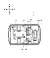
- the battery pack 1 is mainly composed of a case 10, a battery set 11, a circuit board 12, and an IC tag 13.
- the battery pack 11 is charged by connecting the battery pack 1 and the charging device 2.
- the electric power tool 3 is driven by the discharge of the battery set 11 in a state where the battery pack 1 and the electric power tool 3 are connected.
- the battery pack 1 is connected to the charging device 2 or the electric tool 3 to be connected by sliding (sliding) in the first direction from the rear to the front in FIG.
- the case 10 is a part that forms the outline of the battery pack 1 constituted by the upper case 10A and the lower case 10B, and the battery set 11, the circuit board 12, and the IC tag 13 are accommodated therein. Yes.
- the upper case 10A is substantially the upper half of the case 10 and includes a device connection portion 10C.
- the device connection unit 10C is formed in a shape that can be connected to the charging device 2 and can be connected to the electric power tool 3.
- the electric tool 3 and the battery pack 1 are electrically and mechanically connected by being electrically and mechanically connected and connecting the device connecting portion 10 ⁇ / b> C to the electric tool 3.
- the upper case 10 ⁇ / b> A has an opposing wall 10 ⁇ / b> D that faces the charging device 2 or the electric tool 3 in a state where the battery pack 1 is connected to the charging device 2 or the electric tool 3.
- the lower case 10 ⁇ / b> B forms a substantially lower half of the case 10 and mainly provides a space for accommodating the battery set 11.
- the device connection unit 10C is an example of a connection unit.
- the battery set 11 has a configuration in which five cells 11A are connected in series by a plurality of connection plates 11B.
- the battery cell 11A is a rechargeable lithium ion battery, and the rated voltage is 3.60V.
- the battery cell 11A is an example of a secondary battery cell.
- the circuit board 12 is provided above the battery set 11 inside the case 10 and includes a connection terminal portion 12A.
- An electric circuit connected to the battery set 11 is mounted on the circuit board 12, and the electric circuit is connected to a protection IC.
- the circuit board 12 is an example of a board, and the electric circuit is an example of a circuit unit.
- connection terminal portion 12 ⁇ / b> A is provided on the upper front side of the circuit board 12.
- the connection terminal portion 12A is composed of a plurality of terminals arranged side by side in the left-right direction.
- the plurality of terminals are a charge plus terminal 12a, a discharge plus terminal 12b, and a charge / discharge minus terminal 12c.
- a stop signal output terminal 12d is disposed on the front side in the first direction, and an IC tag 13 described later is disposed behind the connection terminal portion 12A (rear side in the first direction). With this arrangement, the connection terminal portion 12A can be connected to the connection target terminal portion without the IC tag 13 getting in the way when the battery pack 1 is connected to the connection target.
- the charge plus terminal 12a and the discharge plus terminal 12b are connected to the plus terminal of the battery cell 11A having the highest potential in the battery set 11 via an electric circuit.
- the charge / discharge minus terminal 12c is connected to the minus terminal of the battery cell 11A having the lowest potential in the battery set 11 via an electric circuit.
- the stop signal output terminal 12d is connected to the protection IC.
- the protection IC monitors the voltage of each of the battery cells 11A, and if any one of them is overcharged or overdischarged, a stop signal for stopping charging or discharging is brought about when the state becomes a non-normal state. Output from the stop signal output terminal 12d.
- the IC tag 13 is a passive tag type non-contact communication IC chip with an antenna, and is provided on the inner surface (surface on the battery assembly 11 side) of the facing wall 10D of the upper case 10A.
- the IC tag 13 stores battery information related to the battery set 11. That is, the battery assembly 11, the circuit board 12, and the IC tag 13 are arranged in this order in the case 10 from the bottom (the bottom surface side of the lower case 10B) to the top, and the information faces the IC tag 13 so as to cover the information.
- a wall 10D is provided.
- connection terminal portion 12A is provided on the front side of the IC tag 13, and the IC tag 13 is not protruded upward from the upper end portion of the connection terminal portion 12A or a position lower than the connection terminal portion 12A in the vertical direction. Position). That is, in the vertical direction, the IC tag 13 is provided at a position avoiding the connection terminal portion 12A (specifically, behind the connection terminal portion 12A).
- the connection terminal portion 12A is connected to the terminal portion of the charging device 2 or the electric tool 3, so that the IC tag 13 is located near the connection terminal portion 12A.
- the IC tag 13 Since the distance to the connection target (charging device 2 or power tool 3) can be shortened by providing the reader / writer described later on the connection terminal portion to be connected, the information on the IC tag 13 can be reliably obtained. Can be read. Furthermore, since the opposing wall 10D is provided above the IC tag 13, the IC tag 13 can be protected from external force. Further, the IC tag 13 is arranged avoiding the connection terminal portion 12A in the vertical direction (the IC tag 13 is arranged behind the connection terminal portion 12A in the front-rear direction in FIG. 1), and the circuit board 12 of the connection terminal portion 12A. The IC tag 13 is positioned below the upper end of the end that is not connected to the terminal.
- a portion of the case 10 avoiding the connection terminal portion 12A is a space, and by providing the IC tag 13 there, the space in the case can be effectively utilized without enlarging the case 10.
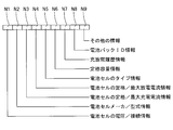
- FIG. 3 is a diagram conceptually showing a storage area of the IC tag 13, and battery information related to the battery set 11 is stored in each of the areas N1 to N9.
- the areas N1 to N6 and N8 are storage areas that are restricted from being updated (changed, written, etc.), and the areas N7 and N9 are updatable storage areas.
- the rated voltage, the maximum charging voltage, the overdischarge voltage, the connection form that is, the number of parallel connections, of the plurality of battery cells 11A constituting the battery set 11 Stores the number of series connections. Further, from the “battery cell voltage / connection information”, the rated voltage, the maximum charging voltage, the overdischarge voltage, and the like of the entire battery set 11 can be calculated. In this embodiment, the rated voltage is 3.60 V, the maximum charging voltage is 3.80 V, the overdischarge voltage is 3.40 V, the number of parallel connections is 1, and the number of series connections is 5.
- the rated voltage per cell is 3.60 V
- the maximum charging voltage is 3.80 V
- the number of series connections is 5. Therefore, the rated voltage of the entire battery group 11 is 18.0 V (3. 60V / cell ⁇ 5 cells) and the maximum charging voltage is 19.0V (3.80V / cell ⁇ 5 cells).
- the battery cell manufacturer / model information the name of the cell manufacturer that manufactured the battery cell 11A and the model attached by the cell manufacturer are stored.
- the cell manufacturer of the battery cell 11A is S
- the model is AAAA.
- the rated charging current and the maximum charging current of the entire battery set 11 are stored as “battery cell rating / maximum charging current information”.
- the rated charging current is a current suitable for reliably charging a plurality of battery cells 11A constituting the battery set 11 until full charge, and is determined by a cell manufacturer or the like in consideration of characteristics, safety, etc. of the battery cell 11A.
- the maximum charging current is the maximum current value that is acceptable for short-time charging such as rapid charging. In the present embodiment, the rated charging current is 4A and the maximum charging current is 6A.
- the region N3 stores an end current value used to determine that the battery is fully charged when performing constant current / constant voltage control.
- the rated discharge current and the maximum discharge current of the battery cell 11A are stored as “battery cell rating / maximum discharge current information”.
- the rated discharge current is a current value suitable when the battery cell 11A is continuously discharged, and is a value determined by a cell manufacturer in consideration of the characteristics, safety, etc. of the battery cell 11A.
- the maximum discharge current is the maximum current value that can be tolerated for a short-time discharge. In the present embodiment, the rated discharge current is 20A and the maximum discharge current is 40A.
- the shape of the battery cell 11A for example, a cylindrical shape, a flat shape, or the like is stored.
- battery cell 11A is cylindrical.
- the rated capacity of the battery set 11 including a plurality of battery cells 11A is stored as “rated capacity information”.
- the rated capacity of the battery set 11 is 5 Ah.
- charge / discharge history information the number of times of charge, the accumulated charge time, the type of the charging device when charged, the number of discharges, the accumulated discharge time, the type of the discharged electric tool, the number of times of overcurrent, The number of overcharges and overdischarges are stored.
- the number of times of charge, the cumulative charge time, the type of charging device when charged, the number of times of overcurrent, the number of times of overcharge, and the number of times of overdischarge are examples of charge history information.
- the number of discharges, the cumulative discharge time, the type of the discharged electric tool, the number of overcurrents, the number of overcharges, and the number of overdischarges are examples of discharge history information.
- battery pack ID information a unique management number assigned when the battery pack 1 is manufactured is stored as “battery pack ID information”.
- charge control or discharge control such as a charge processing program, a discharge processing program, a table relating to a charging current used in the charging processing program, a table relating to a maximum duty used in the discharging processing program ( Various information used for charge / discharge control is stored.
- the region N9 has a charge processing program configured to be processed according to the flowchart shown in FIG. 8, a discharge processing program configured to be processed according to the flowchart shown in FIG.
- the first charging current determination table shown in FIG. 10 the second charging current determination table shown in FIG. 10
- the charging device 2 mainly includes a housing 20, a charging circuit board 21, and a reader / writer 22.
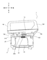
- FIG. 4 is a diagram showing a state where battery pack 1 and charging device 2 are connected.
- the housing 20 is a part forming the outline of the charging device 2 configured in a substantially rectangular parallelepiped shape, and is formed of a heat resistant resin.
- a charging connection portion 20 ⁇ / b> A that can be connected to the battery pack 1 is formed on the surface of the housing 20 that faces the battery pack 1.
- the charging circuit board 21 is a board having a substantially rectangular shape in plan view disposed inside the housing 20, and mainly includes a charging circuit and a charging side microcomputer 21B.
- the charging circuit is mounted on the charging circuit board 21 and includes a predetermined circuit necessary for charging the battery pack 1 and charging control. Further, the charging circuit is connected to the output terminal portion 21A connected to the connection terminal portion 12A of the battery pack 1 via the charging connection portion 20A by wiring.
- the output terminal portion 21A has an output plus terminal, an output minus terminal, and a charge side control terminal. With the charging device 2 and the battery pack 1 connected, the output plus terminal is connected to the charging plus terminal 12a of the battery pack 1, the output minus terminal is connected to the charging / discharging minus terminal 12c of the battery pack 1, and the charging side The control terminal is connected to the stop signal output terminal 12d of the battery pack 1.
- the output terminal portion 21A is the front in the sliding direction of the battery pack 1 (the first direction, the direction from right to left on the paper surface of FIG. 4, ie, the direction from the rear to the front in the direction shown in FIG. 4). 4 (the left side on the paper surface of FIG. 4, that is, the front side in the direction shown in FIG.
- the output terminal portion 21A is an example of a charging terminal portion.
- the charging-side microcomputer 21B is mainly configured by a plurality of input / output ports mounted on the charging circuit board 21, a storage unit for storing various data, processing programs, and the like, and an arithmetic unit, and is equipped with an OS (operation system). is doing.
- the charging-side microcomputer 21B processes various signals input to each input port from a charging circuit or the like, and outputs various signals based on the results from each output port to the charging circuit to control the charging operation.
- the charging side microcomputer 21B has a communication function for communicating with an external device (PC, tablet terminal, etc.).
- the charging circuit and charging side microcomputer 21B function as a charging control means.
- the charging side microcomputer 21B functions as a charging information communication unit, and the storage unit of the charging side microcomputer 21B functions as a charging storage unit.
- the reader / writer 22 is a device that can read battery information stored in the IC tag 13 of the battery pack 1 and update (change, write, etc.) the battery information stored in the IC tag 13 by non-contact communication.
- the charging side microcomputer 21B is connected.
- the reader / writer 22 is disposed on the inner surface of the housing 20 so as to overlap with the IC tag 13 when viewed in the vertical direction in a state where the battery pack 1 and the charging device 2 are connected.
- the reader / writer 22 functions as a reading unit and an updating unit.
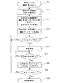
- the charging device 2 performs the charging process according to the flowchart shown in FIG. 8 by following the charging process program read from the IC tag 13.
- S1 when the battery pack 1 is connected to the charging device 2, the connection state shown in FIG. 4 is established, and the battery information stored in the IC tag 13 of the battery pack 1 is read by the reader / writer 22 of the charging device 2 ( S2). In S2, all of the battery information described above is read by the reader / writer 22 and stored in the storage unit of the charging side microcomputer 21B. The stored battery information is used for charge control.
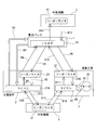
- S2 corresponds to the arrows R1 and R2 shown in FIG.
- the charging side microcomputer 21B determines the charging condition based on the battery information read from the IC tag 13.
- the charging condition is determined by determining the charging voltage and then the charging current.
- the charging voltage is determined based on the maximum charging voltage and the number of series connections in the read battery information. Specifically, the number obtained by multiplying the maximum charging voltage by the number of series connections is defined as the charging voltage. In the present embodiment, it is 19.0 V (3.80 V / cell ⁇ 5 cells).
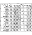
- the charging current is determined according to the first charging current determination table shown in FIG. 9 in the read battery information.
- the first charging current determination table is a table for determining a reference charging current based on information on the battery set 11, the battery cell 11A constituting the battery set 11 and the type of the charging device without considering the number of times of charging. is there.
- the number of parallel connections of the battery set 11 is 1, the cell manufacturer is S, the cell type is AAAA, the rated battery voltage is 3.60 V, and the charging device type is CG-100, so the reference charging current is 1.5A. It is stored in advance in the storage unit of the charging side microcomputer 21B of the charging device 2.
- the 1st charging current determination table is comprised so that the charging current suitable for charge may be defined based on the information regarding the type of the battery set 11, the battery cell 11A which comprises the battery set 11, and the charging device 2. . Further, since the performance of the charging device, that is, the maximum output current is different if the charging device type is different, the first charging current determination table is defined so as to make the best use of the performance of the charging device.
- the maximum output current of the charging device is CG-100 ⁇ CG-200 ⁇ CG-300 ⁇ CG-400 ⁇ CG-500 ⁇ CG-600.
- the charging current is further determined in consideration of the number of times of charging in S4 (the charging current is corrected based on the number of times of charging). Specifically, the charging current is determined according to the second charging current determination table.
- the second charging current determination table is a table for determining a reference charging current based on information on the battery set 11, the battery cell 11A constituting the battery set 11 and the type of the charging device in consideration of the number of times of charging. .
- the number of parallel connections of the battery group 11 is 1, the cell manufacturer is S, the cell type is AAAA, the rated battery voltage is 3.60 V, and is finally determined when the number of times of charging is 250, for example.
- Charging current is 1.5A. In the present embodiment, for example, when the charging current is 1100 times, the finally determined charging current is 1.0 A.
- the second charging current determination table is configured to decrease the charging current as the number of times of charging increases.
- the deterioration degree of the battery cell 11A is estimated from the number of times of charging, and the charging current is determined (the charging current determined in S3 is corrected according to the deterioration degree in S4).
- This burden can be reduced and the battery cell 11A can have a long life.
- the degree of deterioration of battery cell 11A is determined only from the number of times of charging.
- the degree of deterioration of battery cell 11A may be determined from the number of times of charging and the charging time. In this case, the degree of deterioration can be determined more accurately.
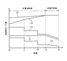
- FIG. 11 is a diagram showing temporal changes in current and voltage in charge control, and shows five charge controls of controls C1 to C5 that are different from each other as an example.
- Control C1 is charging control performed according to the charging conditions and the charging process program determined in the present embodiment, and shows only the charging current when charging is performed by control C1.
- the control C1 is a charge processing program stored in the area N9 of the IC tag 13.
- the control C1 performs charging (constant current control) while maintaining the charging current at 1.5 A, and after the charging voltage reaches 19.0 V (t3), the charging voltage is changed to 19.
- This is constant current / constant voltage charging control in which charging is terminated when charging continues (constant voltage control) while maintaining 0 V and the charging current reaches a predetermined value in the constant voltage control section.
- the control C1 corresponds to the arrow R3 shown in FIG.
- the charging control is performed according to the control C2 or the control C3.
- the control C2 and the control C3 are charged while maintaining the charging current at a predetermined value (constant current control), and the charging is performed every time the charging voltage exceeds the predetermined value (t1, t2).
- the charging current in the constant current control section is sequentially decreased, and after the charging voltage reaches the voltage value for shifting to the constant voltage control (t3), charging is continued while maintaining the charging voltage at the voltage value (constant constant).
- Voltage control) and constant current constant voltage charge control that terminates charging when the charge current reaches a predetermined value in the constant voltage control section.
- the charging control is performed according to the control C4 or the control C5.
- the control C4 gradually increases the charging voltage, and after the charging voltage reaches a predetermined value (t1), charging is performed by making the rising slope of the charging voltage smaller than t0 to t1.
- the charging voltage reaches the voltage value for shifting to the constant voltage control (t3), the charging is continued in the constant voltage control section while maintaining the charging voltage at the voltage value (constant voltage control). This is charge control that terminates charging when the current reaches a predetermined value.
- the control C5 increases the charging voltage with a certain gradient, and after the charging voltage reaches the voltage value for shifting to the constant voltage control (t3), the charging voltage is changed to the voltage.
- charging is terminated when charging is continued (constant voltage control) while maintaining a value and the charging current reaches a predetermined value in the constant voltage control section.
- the charging side microcomputer from the stop signal output terminal 12d of the battery pack 1 via the charging side control terminal of the charging device 2 is used.
- a stop signal for stopping charging is output to 21B.
- the charging device 2 stops charging.
- the output of the stop signal corresponds to the arrow R4 shown in FIG.
- the charging history information is updated in S7 (writing to the IC tag 13 is performed).
- the charging microcomputer 21B uses the reader / writer 22 to store the number of times of charging stored in the area N7 of the IC tag 13, the type of the charging device 2 when charged, the number of times of overcharging, and overdischarge. Update the number of times Writing to the IC tag 13 by the charging side microcomputer 21B corresponds to the arrows R5 and R6 shown in FIG. After the writing to the IC tag 13 is finished in S7, the charging control is finished in S8.
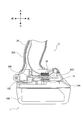
- FIG. 5 is a diagram illustrating a state in which the battery pack 1 and the electric tool 3 are connected.
- the housing 30 is an outer part of the electric power tool 3 and includes a handle portion 30 ⁇ / b> A.
- the handle portion 30A is a portion extending in the vertical direction that is gripped by the user, and a tool connection portion 30B is formed in the lower portion thereof.
- the handle portion 30A includes a trigger switch that drives the motor 33 by a user operation.
- the tool connection unit 30B is configured to be connectable to the device connection unit 10C of the battery pack 1, and has an input plus terminal and an input minus terminal to which a discharge voltage from the battery pack 1 is input, and a tool side control terminal. Yes.
- the input plus terminal, the input minus terminal, and the tool side control terminal function as a tool terminal portion.
- Tool connecting portion 30B is the front side in the sliding direction of battery pack 1 (the first direction, the direction from right to left on the paper surface of FIG. 5, that is, the direction from the rear to the front in the direction shown in FIG. 5). (It is the left side on the paper surface of FIG. 5 and the rear side when viewed from the tool), and the rear side thereof (the right side on the paper surface of FIG. 5, that is, the rear side in the direction shown in FIG. A reader / writer 32 to be described later is arranged on the front side. With this configuration, when the battery pack 1 is slidably connected to the electric tool 3, the terminals can be connected without the reader / writer 32 getting in the way.
- the tool-side microcomputer 31 is mounted on a board disposed inside the electric tool 3, and includes a plurality of input / output ports, a storage unit that stores various data, processing programs, and the like, and an arithmetic unit
- the system is mainly configured with an OS (operation system).
- the tool-side microcomputer 31 processes various signals input to each input port from the discharge control circuit or the like, and outputs various signals based on the results from each output port to the discharge control circuit to control the discharge operation.
- the tool side microcomputer 31 is provided with the communication function which communicates with external apparatuses (PC, a tablet terminal, etc.).
- the discharge control circuit and the tool side microcomputer 31 function as a discharge control means.
- the tool side microcomputer 31 functions as a discharge information communication means
- the storage unit of the tool side microcomputer 31 functions as a discharge storage unit.
- the reader / writer 32 is a device that can read battery information stored in the IC tag 13 of the battery pack 1 and update (change, write, etc.) the battery information stored in the IC tag 13 by non-contact communication.
- the tool side microcomputer 31 is connected.
- the reader / writer 32 is disposed on the inner side surface of the lower portion of the handle portion 30A and overlaps with the IC tag 13 of the battery pack 1 when viewed from the top and bottom with the battery pack 1 and the electric tool 3 connected. Yes.
- the reader / writer 32 functions as a reading unit and an updating unit.
- the motor 33 is a three-phase DC brushless motor and is driven by a discharge control circuit.
- the discharge control circuit has a switching circuit composed of six FETs, and changes the ON time of a predetermined FET (changes the duty) based on a signal from the tool side microcomputer 31 to the motor 33. The amount of power supply is adjusted. That is, the discharge control circuit performs PWM control.
- the discharge control circuit has a rotation speed detection unit that detects the rotation speed of the motor 33, and the rotation speed detection unit outputs the rotation speed of the motor 33 to the tool-side microcomputer 31.
- the arrow R7 shown in FIG. 7 corresponds to discharge control including PWM control, and the rotational speed information from the rotational speed detector corresponds to the arrow R8.
- the electric power tool 3 performs a charging process according to the flowchart shown in FIG. 12 by following the discharge process program read from the IC tag 13.
- S11 when the battery pack 1 is connected to the electric tool 3, the connection state shown in FIG. 5 is established, and the battery information stored in the IC tag 13 of the battery pack 1 is read by the reader / writer 32 of the electric tool 3 ( S12).
- S ⁇ b> 12 all the battery information described above is read by the reader / writer 32 and stored in the storage unit of the tool side microcomputer 31. The stored battery information is used for discharge control.
- S12 corresponds to the arrows R9 and R10 shown in FIG.
- the tool side microcomputer 31 determines the maximum duty based on the battery information read from the IC tag 13.
- the maximum duty is determined according to the maximum duty determination table shown in FIG. 13 of the battery information.
- the maximum duty determination table determines a reference maximum duty based on information on the number of battery cells 11A constituting the battery set 11 connected in series, the number of parallel connections, the cell manufacturer, and the cell type without considering the number of discharges and the discharge time. It is a table to do.
- the number of series connections of the battery set 11 is 5 cells
- the number of parallel connections is 1
- the cell manufacturer is S
- the cell type AAAA
- the standard maximum duty is 80%.
- the duty is a duty of six FETs of an inverter circuit (switching circuit) for driving the motor 33.
- the maximum duty determination table is configured to determine the duty suitable for discharging based on the battery set 11, the battery cell 11 ⁇ / b> A constituting the battery set 11, and the information on the type of the charging device 2.
- the maximum duty is further determined in S14 in consideration of the number of times of charge and the accumulated charge time (the maximum duty is corrected based on the number of discharges and the accumulated discharge time). Since it can be estimated that the deterioration degree of the battery cell 11A increases as the number of discharges and the discharge time increase, a correction value corresponding to the deterioration degree of the battery pack 1 is determined based on the number of discharges and the cumulative discharge time in S14. Multiply the maximum duty determined in step 1 by the correction value.
- the correction value is preferably reduced as the number of times of charging and the charging time increase.
- FIG. 14 is a diagram showing the maximum duty determined in the discharge control of the electric power tool 3 for the battery packs A to C with different degrees of deterioration of the battery cells, and the pulse width output to a predetermined FET of the switching circuit (Pulse width of the signal from the tool-side microcomputer 31).
- the degree of deterioration is the lowest and the maximum duty is determined to be 100%.
- the degree of deterioration is medium and determined to 80%. The highest degree is 60%.
- the maximum duty is determined by estimating the deterioration degree of the battery cell 11A from the number of discharges and the discharge time (the maximum duty determined in S13 is corrected in accordance with the deterioration degree in S14), so that the battery during discharge is discharged.
- the burden on the cell 11A can be reduced, and the battery cell 11A can have a long life.
- the degree of deterioration of the battery cell 11A is determined from the number of discharges and the discharge time.
- the degree of deterioration of the battery cell 11A may be determined from only the number of discharges. Also good.
- the trigger switch is turned on in S15. If the trigger switch is not turned on (No in S15), S15 is repeated until the trigger switch is turned on. On the other hand, when the trigger switch is turned on (Yes in S15), discharging is started in S16 (drive control of the motor 33 is started). When the discharge is started, the motor 33 is subjected to PWM control in a range not exceeding the maximum duty finally determined in S14.
- the charge-side microcomputer from the stop signal output terminal 12d of the battery pack 1 through the tool-side control terminal of the electric tool 3 is used.
- a stop signal for stopping charging is output to 21B.
- the discharge stop condition is when the trigger switch is OFF or when a stop signal is output from the battery pack 1. If the discharge stop condition is not satisfied (No in S17), S17 is repeated until the discharge stop condition is satisfied.
- the tool-side microcomputer 31 uses the reader / writer 32 to store the number of discharges stored in the area N7 of the IC tag 13, the discharge time, the type of the electric tool 3 when discharged, and the number of overcharges. Update the number of overdischarges.
- the update of the discharge history information stored in the IC tag 13 by the tool side microcomputer 31 corresponds to the arrows R11 and R12 shown in FIG.
- the model of the electric power tool 3 is stored in the storage unit of the tool side microcomputer 31.
- FIG. 6 is a diagram showing the external device 4 to which a reader / writer 41 capable of reading and writing battery information stored in the IC tag 13 is connected.
- the external device 4 is, for example, a PC or a tablet terminal.
- the external device 4 can read the battery information stored in the IC tag 13 using the connected reader / writer 41 and display the battery information on a liquid crystal screen or the like provided in the external device. Reading battery information stored in the IC tag 13 by the external device 4 corresponds to the arrow R13 in FIG.
- the battery information stored in the IC tag 13 can be displayed on the liquid crystal screen or the like in the battery pack 1 in the present embodiment, the user takes out the battery set 11 or the battery cell 11A from the battery pack 1. There is no need to check the model etc. Further, it is possible to update (change, write, etc.) battery information stored in the IC tag 13 using the reader / writer 41. For example, more appropriate charge / discharge control can be performed by updating the charge processing program or the discharge processing program stored in the IC tag 13 to the latest one. The update of the battery information stored in the IC tag 13 by the external device 4 corresponds to the arrow R14 in FIG.
- the external device 4 can display information stored in the storage unit of the charging side microcomputer 21B on the liquid crystal screen or the like using the communication function of the charging side microcomputer 21B of the charging device 2. Reading of information stored in the charging device 2 by the external device 4 corresponds to an arrow R15 shown in FIG. Similarly, information stored in the storage unit of the tool-side microcomputer 31 can be displayed on a liquid crystal screen or the like using the communication function of the tool-side microcomputer 31 of the electric power tool 3. Reading of information stored in the electric tool 3 by the external device 4 corresponds to an arrow R17 shown in FIG.
- the external device 4 can update (change, write, etc.) information stored in the storage unit of the charging side microcomputer 21B using the communication function of the charging side microcomputer 21B of the charging device 2.
- the update of the information stored in the charging device 2 by the external device 4 corresponds to the arrow R16 shown in FIG.
- information stored in the storage unit of the tool-side microcomputer 31 can be updated (changed, written, etc.) using the communication function of the tool-side microcomputer 31 of the electric power tool 3. Reading of information stored in the electric tool 3 by the external device 4 corresponds to an arrow R18 shown in FIG.
- the battery pack 1 can be connected to the battery set 11 including the plurality of battery cells 11A and the charging device 2 that houses the battery set 11 and charges the battery set 11.
- the battery assembly includes a case 10 provided with a device connection portion 10C that can be connected to the electric power tool 3 that is driven by the discharge of the battery assembly 11, and an IC tag 13 that stores battery information regarding the battery assembly 11. 11, that is, the rated voltage, the number of parallel connections, the number of series connections, and the like of the battery cells 11 ⁇ / b> A constituting the battery set 11 can be stored in the IC tag 13.
- the charging device 2 or the electric tool 3 can accurately determine the type of the battery set 11, and the appropriate Charge control or discharge control is possible.
- the IC tag 13 includes various rated charge current, maximum charge current, rated discharge current, maximum discharge current, end current, etc. Since a large amount of information can be stored as battery information related to the battery set, the stored battery information can be used for charge control or discharge control, so that detailed control can be performed, and more appropriate charge control or discharge control can be performed. It becomes possible.
- the battery set 11, the circuit board 12, and the IC tag 13 are arranged in order from the bottom in the case 10, the IC tag 13 is arranged at a position close to the connection target, so that the connection target surely reads the information of the IC tag 13. be able to. Further, since the IC tag 13 is provided so as not to protrude upward from the upper end of the connection terminal portion 12A, the battery pack 1 does not increase in size.
- the charging device 2 includes a reader / writer 22 that can read battery information stored in the IC tag 13 and a charging circuit that performs charging control based on the battery information and a charging-side microcomputer 21B. 2 can read battery information stored in the IC tag 13 of the battery pack 1, and charging control based on the battery information is performed on the battery set 11. Thereby, the battery set 11 is charged by appropriate charge control corresponding to the type of the battery set 11.
- the IC tag 13 and the reader / writer 22 are in a position overlapping each other when viewed from above and below, so that the distance between them can be shortened and the information on the IC tag 13 can be read reliably. Can do.
- the battery information includes the charge history information
- the degree of deterioration of the battery set 11 or the battery cell 11A can be determined from the charge history information. For this reason, charge control in consideration of the degree of deterioration becomes possible, and more appropriate charge control can be performed.
- the electric tool 3 since the electric tool 3 includes a reader / writer 32 that can read battery information stored in the IC tag 13 and a discharge control circuit that performs discharge control based on the battery information and the tool side microcomputer 31, the electric tool 3 Can read battery information stored in the IC tag 13 of the battery pack 1, and discharge control based on the battery information is performed on the battery set 11. Thereby, more appropriate discharge control according to the kind of battery group 11 accommodated in the battery pack 1 is performed.
- the IC tag 13 and the reader / writer 32 are positioned so as to overlap each other when viewed from above and below, so that the distance between them can be shortened and information on the IC tag 13 can be read reliably. Can do.
- the battery information includes the discharge history information
- the degree of deterioration of the battery set 11 or the battery cell 11A can be determined from the discharge history information. For this reason, discharge control in consideration of the degree of deterioration becomes possible, and more appropriate discharge control can be performed.
- the IC tag 13 is provided on the inner side surface of the case, adhesion of water droplets, dust, dust, etc., impact from the outside of the case 10 and the like can be suppressed. For this reason, the IC tag 13 can have a long life.
- the case 10 has a facing wall 10D that faces the charging device 2 or the power tool 3 in a state where the device connection portion 10C is connected to the charging device 2 or the power tool 3, and the IC tag 13 is placed on the facing wall 10D. Since the IC tag 13 is provided, the IC tag 13 is located in the vicinity of the charging device 2 or the electric power tool 3. Thereby, the charging device 2 or the power tool 3 can reliably and easily read the battery information stored in the IC tag 13.
- the circuit board 12 on which an electric circuit connected to the battery set 11 housed in the case 10 is mounted and the IC tag 13 is provided on the circuit board 12 the circuit board 12 is provided in the assembly process. After the IC tag 13 is attached in advance, the circuit board 12 can be accommodated in the case 10. Thereby, the assembly property of the battery pack 1 can be improved.
- the charging device 2 includes a reader / writer 22 that can read battery information stored in the IC tag 13, a charging circuit that controls charging of the battery set 11 based on the battery information, and a charging-side microcomputer 21B. Therefore, the battery information related to the battery set stored in the IC tag 13 included in the battery pack 1 can be read, and charging control can be performed based on the battery information. Thereby, the charging device 2 can perform appropriate charge with respect to the battery group 11 which is charging object.
- the charging device 2 includes the reader / writer 22 that can update the battery information stored in the IC tag 13, the battery information can be updated to newer information. Thereby, charge control can be performed based on new information, and more appropriate charge control is possible.
- the power tool 3 includes a reader / writer 32 that can read battery information stored in the IC tag 13, a discharge control circuit that performs discharge control of the battery set 11 based on the battery information, and a tool-side microcomputer. 31, battery information related to the battery set 11 stored in the IC tag 13 provided in the battery pack 1 can be read, and discharge control can be performed based on the battery information. Thereby, the electric tool 3 can perform appropriate discharge control.
- the electric power tool 3 includes the reader / writer 32 that can update the battery information stored in the IC tag 13, the battery information can be updated to newer information. Thereby, more appropriate discharge control based on new information becomes possible.
- the same components as those of the battery pack 1 according to the embodiment of the present invention are denoted by the same reference numerals, description thereof is omitted, and only different components are described.
- the battery pack 1 and the battery pack 101 have the same configuration such as battery information stored in the IC tag, connection and charge control with the charging device 2, connection with the electric tool 3, and discharge control. The only difference is the arrangement location.
- the IC tag 113 of the battery pack 101 is provided on the upper surface of the circuit board 12 (surface on the side opposite to the battery set 11). Since the IC tag 113 is provided on the upper surface of the circuit board 12 as described above, the circuit board 12 can be accommodated in the case after the IC tag is attached to the circuit board 12 in advance. Thereby, the assembly property of the battery pack 101 can be improved.
- the battery pack, the charging device, and the electric tool according to the present invention are not limited to the above-described embodiments, and various modifications can be made within the scope of the gist of the invention described in the claims.
- the charging processing program and the discharging processing program are stored in the IC tag 13, and the charging device 2 or the electric power tool 3 reads the program and uses it for charging control or discharging control.
- the charge processing program may be stored in the charging-side microcomputer 21B of the charging device 2 or the discharge processing program may be stored in the tool-side microcomputer 31 of the power tool 3.
- the rated capacity information stored in the area N6 of the IC tag 13 is not used for charge control or discharge control.
- the rated capacity information may be used for charge control or discharge control. Good. In this case, it is possible to calculate the driving time or the time until the charging is completed from the voltage and rated capacity information of the battery set 11 at the time of connection.
Landscapes
- Engineering & Computer Science (AREA)
- Power Engineering (AREA)
- Chemical & Material Sciences (AREA)
- Chemical Kinetics & Catalysis (AREA)
- Electrochemistry (AREA)
- General Chemical & Material Sciences (AREA)
- Microelectronics & Electronic Packaging (AREA)
- Manufacturing & Machinery (AREA)
- Charge And Discharge Circuits For Batteries Or The Like (AREA)
- Secondary Cells (AREA)
- Battery Mounting, Suspending (AREA)
Abstract
Description
Claims (15)
- 一又は複数の二次電池セルにより構成される電池組と、該電池組を収容し、該電池組を充電する充電装置に接続可能且つ該電池組の放電により駆動する電動工具に接続可能な接続部が設けられたケースと、該電池組に関する電池情報を格納するICタグと、を備えることを特徴とする電池パック。
- 該ICタグは、該ケースの内側面に設けられており、該ケースは、該接続部が該充電装置又は該電動工具に接続された状態において該充電装置又は該電動工具と対向する対向壁を有し、該ICタグは、該対向壁に設けられていることを特徴とする請求項1に記載の電池パック。
- 該ケースに収容され、該電池組と接続された回路部が実装された基板を更に備え、該基板に該ICタグが設けられていることを特徴とする請求項1又は2に記載の電池パック。
- 一又は複数の二次電池セルにより構成される電池組と、該電池組の上方に配置され、該二次電池セルに接続される回路基板と、該電池組及び該回路基板を収容し、接続部が設けられたケースと、該回路基板の上方に配置され、該電池組に関する電池情報を格納するICタグと、を備えることを特徴とする電池パック。
- 上下方向において該ICタグは該端子部を避けて設けられていることを特徴とする請求項4に記載の電池パック。
- 該接続部は一端側が該回路基板に接続され、他端側が外部機器に接続される端子を有し、該ICタグは、上下方向において該端子の他端側の上端部又は該上端部よりも下方の位置で該ケース内に設けられていることを特徴とする請求項4又は5に記載の電池パック。
- 一又は複数の二次電池セルにより構成される電池組と、該電池組を収容し接続対象に接続される接続端子部が設けられたケースと、該電池組に関する電池情報を格納するICタグと、を備え、該ケースは該接続対象に対して第1の方向に摺動して接続するように構成され、該第1の方向における前方側に該接続端子部を配置し、後方側に該ICタグを配置したことを特徴とする電池パック。
- 一又は複数の二次電池セルにより構成される電池組と、該電池組に関する電池情報を格納するICタグと、を備える電池パックに接続可能な充電装置であって、該ICタグに格納された該電池情報を読み取り可能な読取手段と、該読取手段が読み取った該電池情報に基づいて該電池組の充電制御を行う充電制御手段と、を備えることを特徴とする充電装置。
- 該電池パックと該充電装置が接続された状態において、該読取手段は該ICタグと対向して配置されることを特徴とする請求項8に記載の充電装置。
- 該電池パックは該充電装置の上方に接続されるように構成され、上下方向から見て該ICタグと該読取手段が重なった位置に配置されることを特徴とする請求項9に記載の充電装置。
- 一又は複数の二次電池セルにより構成される電池組と、該電池組に接続される接続端子部と、該電池組に関する電池情報を格納するICタグと、を備える電池パックに接続可能な充電装置であって、該接続端子部に接続される充電端子部と、該ICタグに格納された該電池情報を読み取り可能な読取手段と、該読取手段が読み取った該電池情報に基づいて該電池組の充電制御を行う充電制御手段と、を備え、該電池パックを第1の方向に摺動することで該接続端子部と充電端子部とが接続されるように構成され、該第1の方向における前方側に該充電端子部を配置し、後方側に該読取手段を配置したことを特徴とする充電装置。
- 一又は複数の二次電池セルにより構成される電池組と、該電池組に関する電池情報を格納するICタグと、を備える電池パックに接続可能な電動工具であって、該ICタグに格納された該電池情報を読み取り可能な読取手段と、該読取手段が読み取った該電池情報に基づいて該電池組の放電制御を行う放電制御手段と、を備えることを特徴とする電動工具。
- 該電池パックと該電動工具が接続された状態において、該読取手段は該ICタグと対向して配置されることを特徴とする請求項12に記載の電動工具。
- 該電池パックは該電動工具の下方に接続されるように構成され、上下方向から見て該ICタグと該読取手段が重なった位置に配置されることを特徴とする請求項13に記載の電動工具。
- 一又は複数の二次電池セルにより構成される電池組と、該電池組に接続される接続端子部と、該電池組に関する電池情報を格納するICタグと、を備える電池パックに接続可能な電動工具であって、該接続端子部に接続される工具端子部と、該ICタグに格納された該電池情報を読み取り可能な読取手段と、該読取手段が読み取った該電池情報に基づいて該電池組の放電制御を行う放電制御手段と、を備え、該電池パックを第1の方向に摺動することで該接続端子部と該工具端子部とが接続されるように構成され、該第1の方向における前方側に該工具端子部を配置し、後方側に該読取手段を配置したことを特徴とする電動工具。
Priority Applications (4)
| Application Number | Priority Date | Filing Date | Title |
|---|---|---|---|
| CN201590000506.0U CN206274616U (zh) | 2014-04-30 | 2015-04-27 | 电池包、充电装置以及电动工具 |
| US15/307,375 US20170047618A1 (en) | 2014-04-30 | 2015-04-27 | Cell pack, charging device and electric tool |
| DE212015000121.0U DE212015000121U1 (de) | 2014-04-30 | 2015-04-27 | Zellenstapel, Ladevorrichtung und elektrisches Werkzeug |
| JP2016516372A JP6195233B2 (ja) | 2014-04-30 | 2015-04-27 | 電池パック、充電システム及び電動工具 |
Applications Claiming Priority (2)
| Application Number | Priority Date | Filing Date | Title |
|---|---|---|---|
| JP2014094235 | 2014-04-30 | ||
| JP2014-094235 | 2014-04-30 |
Publications (1)
| Publication Number | Publication Date |
|---|---|
| WO2015166908A1 true WO2015166908A1 (ja) | 2015-11-05 |
Family
ID=54358635
Family Applications (1)
| Application Number | Title | Priority Date | Filing Date |
|---|---|---|---|
| PCT/JP2015/062680 Ceased WO2015166908A1 (ja) | 2014-04-30 | 2015-04-27 | 電池パック、充電装置及び電動工具 |
Country Status (5)
| Country | Link |
|---|---|
| US (1) | US20170047618A1 (ja) |
| JP (1) | JP6195233B2 (ja) |
| CN (1) | CN206274616U (ja) |
| DE (1) | DE212015000121U1 (ja) |
| WO (1) | WO2015166908A1 (ja) |
Cited By (6)
| Publication number | Priority date | Publication date | Assignee | Title |
|---|---|---|---|---|
| JP2017108604A (ja) * | 2015-11-30 | 2017-06-15 | 株式会社マキタ | バッテリ装置及び充電装置 |
| JP2017184534A (ja) * | 2016-03-31 | 2017-10-05 | 株式会社Gsユアサ | 蓄電素子管理装置、蓄電装置、及び蓄電システム |
| JP2019021594A (ja) * | 2017-07-21 | 2019-02-07 | 工機ホールディングス株式会社 | 電池パック及び電池パックを用いた電気機器 |
| WO2019181669A1 (ja) * | 2018-03-20 | 2019-09-26 | 本田技研工業株式会社 | 管理装置 |
| JP2021015741A (ja) * | 2019-07-12 | 2021-02-12 | パナソニックIpマネジメント株式会社 | 防災照明システム、防災照明器具、電池ユニット及びコンピュータ・プログラム |
| JP2024121733A (ja) * | 2023-02-27 | 2024-09-06 | 工機ホールディングス株式会社 | 電池パック及び電気機器 |
Families Citing this family (7)
| Publication number | Priority date | Publication date | Assignee | Title |
|---|---|---|---|---|
| CN108899972B (zh) * | 2018-10-10 | 2024-05-31 | 宁波九荣环保科技有限公司 | 一种充电器的充电控制电路及其控制方法 |
| JP7803859B2 (ja) * | 2019-12-10 | 2026-01-21 | ミルウォーキー エレクトリック ツール コーポレイション | バッテリパック構成データに基づくガスエンジン代替装置のためのモータ制御 |
| JP7375581B2 (ja) * | 2020-01-28 | 2023-11-08 | 株式会社デンソー | 電池パック |
| US11588336B2 (en) * | 2020-06-16 | 2023-02-21 | Semiconductor Components Industries, Llc | Methods and apparatus for a battery system |
| EP4183023A4 (en) * | 2020-07-20 | 2024-09-04 | Milwaukee Electric Tool Corporation | SYSTEMS, METHODS AND DEVICES FOR INCREASING THE CHARGING RATE OF LITHIUM-BASED BATTERY PACKS |
| JP2024545625A (ja) * | 2021-12-01 | 2024-12-10 | ヒルティ アクチエンゲゼルシャフト | 機械工具と電力供給装置とを有するシステム、インターフェース及び電力供給装置 |
| EP4473634A1 (en) * | 2022-01-31 | 2024-12-11 | Google LLC | Battery zero-voltage detection methodologies and applications thereof |
Citations (5)
| Publication number | Priority date | Publication date | Assignee | Title |
|---|---|---|---|---|
| JPH1066266A (ja) * | 1996-08-22 | 1998-03-06 | Hitachi Ltd | 携帯端末用充電池の管理方法 |
| JP2003168406A (ja) * | 2001-11-30 | 2003-06-13 | Sanyo Electric Co Ltd | 真贋判別回路を備えるパック電池 |
| JP2008113551A (ja) * | 2003-11-19 | 2008-05-15 | Milwaukee Electric Tool Corp | 電池充電器 |
| WO2008153138A1 (ja) * | 2007-06-13 | 2008-12-18 | Kyocera Corporation | 充電システム、携帯電子機器及びこれに用いられる電池端子、並びに二次電池 |
| WO2009069201A1 (ja) * | 2007-11-28 | 2009-06-04 | Olympus Medical Systems Corp. | 電池管理システムおよび充電器 |
Family Cites Families (1)
| Publication number | Priority date | Publication date | Assignee | Title |
|---|---|---|---|---|
| JP5151506B2 (ja) | 2008-01-28 | 2013-02-27 | 日立工機株式会社 | 電池パックとこれを充電する充電装置及び充電システム |
-
2015
- 2015-04-27 US US15/307,375 patent/US20170047618A1/en not_active Abandoned
- 2015-04-27 WO PCT/JP2015/062680 patent/WO2015166908A1/ja not_active Ceased
- 2015-04-27 JP JP2016516372A patent/JP6195233B2/ja active Active
- 2015-04-27 CN CN201590000506.0U patent/CN206274616U/zh not_active Expired - Fee Related
- 2015-04-27 DE DE212015000121.0U patent/DE212015000121U1/de not_active Expired - Lifetime
Patent Citations (5)
| Publication number | Priority date | Publication date | Assignee | Title |
|---|---|---|---|---|
| JPH1066266A (ja) * | 1996-08-22 | 1998-03-06 | Hitachi Ltd | 携帯端末用充電池の管理方法 |
| JP2003168406A (ja) * | 2001-11-30 | 2003-06-13 | Sanyo Electric Co Ltd | 真贋判別回路を備えるパック電池 |
| JP2008113551A (ja) * | 2003-11-19 | 2008-05-15 | Milwaukee Electric Tool Corp | 電池充電器 |
| WO2008153138A1 (ja) * | 2007-06-13 | 2008-12-18 | Kyocera Corporation | 充電システム、携帯電子機器及びこれに用いられる電池端子、並びに二次電池 |
| WO2009069201A1 (ja) * | 2007-11-28 | 2009-06-04 | Olympus Medical Systems Corp. | 電池管理システムおよび充電器 |
Cited By (8)
| Publication number | Priority date | Publication date | Assignee | Title |
|---|---|---|---|---|
| JP2017108604A (ja) * | 2015-11-30 | 2017-06-15 | 株式会社マキタ | バッテリ装置及び充電装置 |
| JP2017184534A (ja) * | 2016-03-31 | 2017-10-05 | 株式会社Gsユアサ | 蓄電素子管理装置、蓄電装置、及び蓄電システム |
| JP2019021594A (ja) * | 2017-07-21 | 2019-02-07 | 工機ホールディングス株式会社 | 電池パック及び電池パックを用いた電気機器 |
| WO2019181669A1 (ja) * | 2018-03-20 | 2019-09-26 | 本田技研工業株式会社 | 管理装置 |
| JPWO2019181669A1 (ja) * | 2018-03-20 | 2021-03-11 | 本田技研工業株式会社 | 管理装置 |
| JP2021015741A (ja) * | 2019-07-12 | 2021-02-12 | パナソニックIpマネジメント株式会社 | 防災照明システム、防災照明器具、電池ユニット及びコンピュータ・プログラム |
| JP7312985B2 (ja) | 2019-07-12 | 2023-07-24 | パナソニックIpマネジメント株式会社 | 防災照明システム |
| JP2024121733A (ja) * | 2023-02-27 | 2024-09-06 | 工機ホールディングス株式会社 | 電池パック及び電気機器 |
Also Published As
| Publication number | Publication date |
|---|---|
| JP6195233B2 (ja) | 2017-09-13 |
| JPWO2015166908A1 (ja) | 2017-04-20 |
| CN206274616U (zh) | 2017-06-23 |
| DE212015000121U1 (de) | 2016-12-21 |
| US20170047618A1 (en) | 2017-02-16 |
Similar Documents
| Publication | Publication Date | Title |
|---|---|---|
| JP6195233B2 (ja) | 電池パック、充電システム及び電動工具 | |
| JP7325438B2 (ja) | バッテリー管理装置及び方法 | |
| JP4212333B2 (ja) | 電池、機器、及び充電器 | |
| CN202309104U (zh) | 具有多个单单元电池组的电动工具 | |
| US9287728B2 (en) | Battery pack | |
| US9077179B2 (en) | System for recognizing type of battery management system and characteristics of battery cell | |
| CN102055030B (zh) | 电池组及其驱动方法 | |
| CN109075578A (zh) | 电池管理系统 | |
| JP2009176486A (ja) | バッテリパック及び配線基板 | |
| JP2008117743A (ja) | ハイブリッドバッテリー及びその充電方法 | |
| CN107107327A (zh) | 电动工具 | |
| CN220710392U (zh) | 电池组系统及电池组 | |
| CN104221210A (zh) | 用于自动地识别电池特性的系统、用于该系统的电池信息存储装置、以及用于通过使用该系统自动地优化电池管理装置的方法 | |
| JP4725605B2 (ja) | 充電回路 | |
| JP2010050045A (ja) | 充電器 | |
| WO2017043248A1 (ja) | 電池診断装置及び電池パック | |
| WO2005112241A1 (ja) | Dcアダプタ及びこれを用いた電子機器 | |
| JPH08265984A (ja) | 電源装置 | |
| EP2871701B1 (en) | Battery pack and electric device including the battery pack | |
| JP2006092850A (ja) | 電池パック | |
| GB2545921A (en) | Battery management system | |
| JP2022047802A (ja) | 電子機器、電池パック、制御方法およびプログラム | |
| KR101282027B1 (ko) | 탈착 가능한 보호회로모듈 및 전지셀을 포함하고 있는 노트북 컴퓨터 | |
| JP2009301983A (ja) | 電池パック | |
| KR100709842B1 (ko) | 전지 팩 |
Legal Events
| Date | Code | Title | Description |
|---|---|---|---|
| 121 | Ep: the epo has been informed by wipo that ep was designated in this application |
Ref document number: 15786465 Country of ref document: EP Kind code of ref document: A1 |
|
| ENP | Entry into the national phase |
Ref document number: 2016516372 Country of ref document: JP Kind code of ref document: A |
|
| WWE | Wipo information: entry into national phase |
Ref document number: 15307375 Country of ref document: US |
|
| WWE | Wipo information: entry into national phase |
Ref document number: 212015000121 Country of ref document: DE |
|
| 122 | Ep: pct application non-entry in european phase |
Ref document number: 15786465 Country of ref document: EP Kind code of ref document: A1 |