WO2015166876A1 - 交通信号制御装置、交通信号制御方法、及びコンピュータプログラム - Google Patents
交通信号制御装置、交通信号制御方法、及びコンピュータプログラム Download PDFInfo
- Publication number
- WO2015166876A1 WO2015166876A1 PCT/JP2015/062370 JP2015062370W WO2015166876A1 WO 2015166876 A1 WO2015166876 A1 WO 2015166876A1 JP 2015062370 W JP2015062370 W JP 2015062370W WO 2015166876 A1 WO2015166876 A1 WO 2015166876A1
- Authority
- WO
- WIPO (PCT)
- Prior art keywords
- intersection
- traffic
- signal control
- controller
- inflow
- Prior art date
Links
Images


Classifications
-
- G—PHYSICS
- G08—SIGNALLING
- G08G—TRAFFIC CONTROL SYSTEMS
- G08G1/00—Traffic control systems for road vehicles
- G08G1/07—Controlling traffic signals
- G08G1/081—Plural intersections under common control
-
- G—PHYSICS
- G08—SIGNALLING
- G08G—TRAFFIC CONTROL SYSTEMS
- G08G1/00—Traffic control systems for road vehicles
- G08G1/01—Detecting movement of traffic to be counted or controlled
- G08G1/0104—Measuring and analyzing of parameters relative to traffic conditions
- G08G1/0108—Measuring and analyzing of parameters relative to traffic conditions based on the source of data
- G08G1/0112—Measuring and analyzing of parameters relative to traffic conditions based on the source of data from the vehicle, e.g. floating car data [FCD]
-
- G—PHYSICS
- G08—SIGNALLING
- G08G—TRAFFIC CONTROL SYSTEMS
- G08G1/00—Traffic control systems for road vehicles
- G08G1/01—Detecting movement of traffic to be counted or controlled
- G08G1/0104—Measuring and analyzing of parameters relative to traffic conditions
- G08G1/0108—Measuring and analyzing of parameters relative to traffic conditions based on the source of data
- G08G1/0116—Measuring and analyzing of parameters relative to traffic conditions based on the source of data from roadside infrastructure, e.g. beacons
-
- G—PHYSICS
- G08—SIGNALLING
- G08G—TRAFFIC CONTROL SYSTEMS
- G08G1/00—Traffic control systems for road vehicles
- G08G1/01—Detecting movement of traffic to be counted or controlled
- G08G1/0104—Measuring and analyzing of parameters relative to traffic conditions
- G08G1/0108—Measuring and analyzing of parameters relative to traffic conditions based on the source of data
- G08G1/012—Measuring and analyzing of parameters relative to traffic conditions based on the source of data from other sources than vehicle or roadside beacons, e.g. mobile networks
-
- G—PHYSICS
- G08—SIGNALLING
- G08G—TRAFFIC CONTROL SYSTEMS
- G08G1/00—Traffic control systems for road vehicles
- G08G1/01—Detecting movement of traffic to be counted or controlled
- G08G1/0104—Measuring and analyzing of parameters relative to traffic conditions
- G08G1/0137—Measuring and analyzing of parameters relative to traffic conditions for specific applications
- G08G1/0145—Measuring and analyzing of parameters relative to traffic conditions for specific applications for active traffic flow control
-
- G—PHYSICS
- G08—SIGNALLING
- G08G—TRAFFIC CONTROL SYSTEMS
- G08G1/00—Traffic control systems for road vehicles
- G08G1/07—Controlling traffic signals
- G08G1/08—Controlling traffic signals according to detected number or speed of vehicles
Definitions
- the present invention relates to a traffic signal control device, a traffic signal control method, and a computer program that perform signal light color control of a traffic signal based on traffic volume.
- the conventional signal control method for traffic signals by system control and wide area control can be broadly classified from the viewpoint of setting method of signal control parameters (split, cycle length, offset, etc.).
- signal control parameters split, cycle length, offset, etc.
- the latter traffic sensitive control is classified into terminal sensitive control performed for each traffic signal controller of the terminal and central sensitive control that changes signal control parameters for a plurality of intersections that are route system controlled or surface controlled.
- the inflow traffic to the intersection used for obtaining the signal control parameter is usually acquired by a vehicle detector or the like installed on the road.
- the vehicle detector is preferably installed at all of the intersections to be controlled, but depending on factors such as cost and location conditions, the vehicle detector is not installed. May be mixed.
- the inflow traffic volume cannot be acquired, and the signal control parameter at the intersection cannot be obtained based on the current inflow traffic volume. For this reason, there is a possibility that signal control is not appropriately performed at an intersection where a vehicle sensor is not installed.
- the present invention has been made in view of such a situation, and an object of the present invention is to provide a technique capable of improving the efficiency of traffic processing in the entire area to be controlled.
- a traffic signal control device includes an acquisition unit that acquires an inflow traffic volume at a first intersection defined below, probe traffic information obtained from a traveling vehicle, the acquired inflow traffic volume at the first intersection. Based on at least one of the above, the estimation unit that estimates the inflow traffic volume of the second intersection defined below, and the first controller defined below based on the acquired inflow traffic volume of the first intersection An information processing unit that generates a signal control parameter of the second controller defined below based on the estimated inflow traffic volume of the second intersection, and an information processing unit of the generated first controller A communication unit that transmits a signal control parameter to the first controller and transmits the generated signal control parameter of the second controller to the second controller.
- 2nd intersection intersection where inflow traffic cannot be obtained
- 1st controller traffic signal controller installed at 1st intersection
- 2nd controller installed at 2nd intersection Traffic signal controller
- the signal control method acquires the inflow traffic volume of the first intersection defined below, and the acquired inflow traffic volume of the first intersection and the probe information obtained from the traveling vehicle Based on at least one of the above, the inflow traffic volume of the second intersection defined below is estimated, and the signal control parameter of the first controller defined below is calculated based on the acquired inflow traffic volume of the first intersection. Based on the inflow traffic volume generated and estimated at the second intersection, a signal control parameter of the second controller defined below is generated, and the generated signal control parameter of the first controller is used as the first controller. And the generated signal control parameter of the second controller is transmitted to the second controller.
- 2nd intersection intersection where inflow traffic cannot be obtained
- 1st controller traffic signal controller installed at 1st intersection
- 2nd controller installed at 2nd intersection Traffic signal controller
- the computer program according to an embodiment is a computer program for causing a computer to function as the traffic signal control device described above.
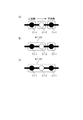
- (A) is a figure for demonstrating the estimation method of the inflow traffic of the 2nd intersection adjacent to a 1st intersection, and has shown the aspect of the intersection.
- (B) has shown the numerical formula used for the said inflow traffic volume for estimation. It is a figure for demonstrating the estimation method of the queue length in the 2nd intersection by the estimation process part of a central apparatus.
- (A) is a figure which shows an example of the signal control by a central apparatus, Comprising: The control area of the state which has not generate
- FIG. 1 is a figure for demonstrating the control aspect regarding the signal control of each intersection concerning a modification, Comprising: The figure which shows the subarea structure in the state where traffic congestion has not generate
- (B) is a figure which shows an example of the subarea structure when the traffic jam is detected in the modified example, and (c) is another example of the subarea configuration when the traffic jam is detected in the modified example.
- a traffic signal control device is obtained from an acquisition unit that acquires an inflow traffic volume of a first intersection defined below, an acquired inflow traffic volume of the first intersection, and a traveling vehicle.
- an estimation unit for estimating the inflow traffic volume of the second intersection defined below, and a first definition defined below based on the acquired inflow traffic volume of the first intersection An information processing unit for generating a signal control parameter for the second controller defined below based on the inflow traffic volume of the second intersection generated by generating a signal control parameter for the first controller, and the generated first A communication unit that transmits a signal control parameter of the controller to the first controller and transmits the generated signal control parameter of the second controller to the second controller.
- the estimation unit estimates the inflow traffic volume at the second intersection based on the inflow traffic volume at the first intersection, the inflow traffic volume at the second intersection is Even if it is not obtained, the signal control parameter of the second controller can be generated based on the inflow traffic estimated by the estimation unit, and the signal control of the second intersection can be appropriately performed.
- the signal control parameter of the second controller can be generated based on the inflow traffic estimated by the estimation unit, and the signal control of the second intersection can be appropriately performed.
- signal control can be appropriately performed at each intersection, and the efficiency of traffic processing in the entire area to be controlled including a plurality of intersections to be controlled Can be achieved.
- Sensitive method Control method that generates signal control parameters for the second controller based on the estimated traffic volume at the second intersection
- Non-sensitive method Currently applied to preset signal control parameters or adjacent first controller Control method that adopts the signal control parameter of 2 as the signal control parameter of the second controller
- the information processing unit can determine whether the first intersection is congested based on the inflow traffic volume of the first intersection, the first intersection is congested.
- the sensitive method is adopted as the control method of the second controller, and when the first intersection is not congested, the non-sensitive method is adopted as the control method of the second controller. it can.
- a suitable signal control system can be selected according to traffic conditions.
- the information processing unit performs a sub-area combination determination process for determining whether to include a plurality of adjacent intersections in the same sub-area according to traffic conditions.
- the predetermined condition is that the first intersection is congested.
- the information processing unit can execute a sub-area combination determination process according to traffic conditions to determine whether or not to include a plurality of adjacent intersections in the same sub-area.
- signal control is performed with a cycle length set for each of a plurality of adjacent intersections, a first evaluation value obtained from a predetermined evaluation condition, a cycle length of each of the plurality of adjacent intersections, and a signal control parameter at each intersection
- determining whether to include a plurality of adjacent intersections in the same subarea based on the comparison between the first evaluation value and the second evaluation value. If it can be determined more appropriately.
- the signal control method which concerns on one Embodiment acquires the inflow traffic of the 1st intersection defined below, and the acquired inflow traffic of the said 1st intersection and the probe obtained from the running vehicle Based on at least one of the information, the inflow traffic of the second intersection defined below is estimated, and the signal of the first controller defined below is estimated based on the acquired inflow traffic of the first intersection.
- a control parameter is generated, a signal control parameter of the second controller defined below is generated based on the estimated inflow traffic volume of the second intersection, and the generated signal control parameter of the first controller is
- 1st intersection intersection where inflow traffic can be obtained
- 2nd intersection intersection where inflow traffic cannot be obtained
- 1st controller traffic signal controller installed at 1st intersection
- 2nd controller installed at 2nd intersection Traffic signal controller
- the computer program which concerns on one Embodiment is a computer program for functioning a computer as a traffic signal control apparatus as described in said (1).
- First intersection An intersection where a road sensor such as a vehicle detector is installed, and an inflow traffic volume that is a traffic volume in the inflow path can be obtained.
- Second intersection An intersection where the inflow traffic cannot be obtained because no roadside sensor such as a vehicle detector is installed.
- First controller means a traffic signal controller installed at the first intersection and performing signal control of the traffic signal installed at the first intersection.
- Second controller A traffic signal controller installed at a second intersection and performing signal control of a traffic signal installed at the second intersection.
- Vehicle All vehicles traveling on the road, specifically, vehicles according to the Road Traffic Act. Vehicles under the law include automobiles, motorbikes, light vehicles and trolley buses.
- vehicle includes both a probe vehicle having an in-vehicle device capable of transmitting probe information and a normal vehicle having no in-vehicle device.
- Vehicle sensor A roadside sensor that detects the presence of vehicles traveling on the road one by one at a fixed position. For example, an ultrasonic vehicle sensor that detects a vehicle passing directly below with an ultrasonic wave, a temperature-type vehicle sensor that detects the passage of a vehicle from a temperature change when the vehicle passes, or a vehicle that detects an inductance change A loop coil embedded in a road corresponds to this.
- Detection signal A pulse signal output when a vehicle detector installed at a predetermined position on a road detects one vehicle. Therefore, when a plurality of vehicles pass through the vehicle detector, sensing signals corresponding to each vehicle are output in time series.
- Probe information Various types of information related to a vehicle obtained from an in-vehicle device of a probe vehicle that actually travels on a road. Sometimes referred to as probe data or floating car data. This includes data such as vehicle ID, vehicle position, vehicle speed, vehicle orientation, and the time of occurrence thereof. Since the vehicle speed can be calculated if the vehicle position and time are known, it is sufficient if the probe information includes the vehicle position and time measured every predetermined time (for example, 1 second). But the vehicle speed for every time may be contained in the probe information.
- “Signal control parameter” Generally refers to cycle length, split, and offset.
- the signal lamp color switching timing (such as the start time and display time of each lamp color) at the intersection is included.
- probe information of a probe vehicle that has passed an intersection in the blue time zone is used for calculating the link travel time. Therefore, the time information (start time) that can specify the start and end of the blue time zone is used as the signal lamp color switching timing. Time and display time or start time and end time).
- “Cycle length” The time of one cycle from the blue (or red) start time of a traffic signal to the next blue (or red) start time. “Split”: The ratio of the time (green signal time, red signal time, etc.) allocated to each display to the cycle length. “Offset”: Refers to the deviation of the green signal start time between adjacent intersections. Expressed as a percentage or second of the time of one cycle.
- “Queue” A queue of vehicles that are stopped in front of an intersection due to waiting for a traffic light with a red light.
- “Intersection traffic jam” A situation where the queue formed in front of the intersection cannot make money in a single green light. Therefore, when the signal queue is opened in one green traffic light time, there is no “traffic jam” at the intersection. Also, it may be determined that no “traffic jam” has occurred even when the queue length greater than a predetermined value is not measured.
- “Road section” A section from an arbitrary point on the road to another arbitrary point. In the present embodiment, the following “link” is assumed as the road section for which the estimated travel time generated from the probe information is calculated.
- “Link” A road section having an upward or downward direction that connects nodes such as an intersection. A link in a direction flowing into the intersection as viewed from a certain intersection is referred to as an inflow link, and a link in a direction flowing out from the intersection as viewed from a certain intersection is referred to as an outflow link.
- “Node” A node on a road expression, such as an intersection or a point where an attribute such as a road type changes.
- “Route” A road section including a plurality of system sections. A boundary link where no system control is performed is included between adjacent system sections.
- System section A road section that performs system control described later. The system section includes approximately 3 to 5 links.
- Sub-area means an area divided so as to include one or a plurality of intersections where traffic signals that are signal-controlled with a common cycle length are installed.
- System control By adjusting the traffic signal offset between the intersections included in a series of system sections set in the sub-area, it is easier to pass a specific direction of the system section with a green light (priority offset), and vice versa The control that makes it easy to stop safely with a red light.
- FIG. 1 is a diagram showing an overall configuration of a traffic signal control system.
- FIG. 2 is a diagram for illustrating the configuration of the traffic signal control system and the flow of information exchange in this system.
- the traffic signal control system according to the present embodiment is equipped with a traffic signal 1, a vehicle-mounted wireless device 2, a roadside sensor 3 including a vehicle detector, a central device 4, and a vehicle-mounted wireless device 2.
- the vehicle 5, the probe information management device 9, and the roadside wireless device 11 installed on the road are included.
- S1 is a signal control command for controlling the switching timing of the signal light color of the traffic signal 1 generated by the central device 4.
- S3 is probe information generated by the vehicle (probe vehicle) 5 on which the in-vehicle wireless device 2 is mounted, and this probe information S3 includes the position, speed, time, and the like of the traveling vehicle 5 for a predetermined time or distance. It is.
- S4 is roadside measurement information (for example, the number of passing vehicles 5) measured by the roadside sensor 3.
- This router 7 is connected to a central device 4 in the traffic control center, and the central device 4 constitutes a local area network (LAN) with a traffic signal controller 1a at each intersection Ci included in a control area under its control. ing.
- LAN local area network
- the central device 4 can perform bidirectional communication with each traffic signal controller 1a, and each traffic signal controller 1a can also perform bidirectional communication with other traffic signal controllers 1a.
- the central device 4 may be installed on the road instead of the traffic control center. Further, in FIG. 1, for simplification of illustration, only one signal lamp 1b is depicted at each intersection Ci. However, in actual intersection Ci, four signal lights are used for ascending and descending roads intersecting each other. A vessel 1b is installed.
- the roadside sensor 3 is, for example, a vehicle detector that ultrasonically senses the vehicle 5 that passes underneath, a loop coil that senses the vehicle 5 by inductance change, or an image of a camera to perform traffic processing and vehicle speed. It consists of an image sensor to measure. As shown in FIG. 2, the roadside sensor 3 is installed on the upstream side of each route extending from the corresponding intersection Ci, and is used for measuring the number of vehicles flowing into the intersection Ci (inflow traffic volume) and the vehicle speed. Of the intersections included in the control area, some of the intersections Ci are installed.
- an intersection Ci (hereinafter also referred to as “first intersection Ci-1”) where the inflow traffic volume can be obtained by installing the roadside sensor 3. )
- an intersection Ci (hereinafter also referred to as “second intersection Ci-2”) where the inflow traffic volume cannot be obtained because the roadside sensor 3 is not installed.
- the roadside sensor 3 is communicably connected to the traffic signal controller 1a via a wired or wireless communication line.
- the roadside sensor 3 outputs the detection result as roadside measurement information S4.
- the roadside measurement information S4 is output from the roadside sensor 3 as information that allows estimation of the number of vehicles 5 passing per unit time, vehicle speed, and the like, relayed by the traffic signal controller 1a, and transferred to the central device 4.
- the roadside apparatus 11 is installed at each intersection Ci.
- the roadside apparatus 11 can perform bidirectional communication with the traffic signal controller 1a via a wired or wireless communication line.
- the roadside wireless device 11 has a function of performing wireless communication with Wi-Fi (registered trademark) or the like with the in-vehicle wireless device 2 of the vehicle 5 traveling around the roadside wireless device 11.
- the roadside apparatus 11 transmits various information given from the central apparatus 4 to the in-vehicle wireless apparatus 2 through the traffic signal controller 1a.
- the roadside apparatus 11 receives the probe information S3 transmitted from the in-vehicle wireless apparatus 2.
- the received probe information S3 is relayed by the traffic signal controller 1a and transferred to the central device 4.
- the in-vehicle wireless device 2 can transmit the probe information S3 generated by the own device 2 in real time to the roadside wireless device 11 by wirelessly connecting to the roadside wireless device 11.
- the in-vehicle wireless device 2 has a function for performing wireless communication with the roadside wireless device 11 by Wi-Fi (registered trademark). It may be configured by a mobile phone.
- the roadside wireless device 11 can collect the probe information S3 through the communication line of the mobile phone.
- the roadside apparatus 11 includes a probe information management apparatus 9 for collecting probe information S3 transmitted by the in-vehicle wireless apparatus 2 configured by a mobile phone through a wireless communication line of the mobile phone.
- This probe information management device 9 acquires the probe information S3 that the in-vehicle wireless device 2 configured by the mobile phone transmits through the communication line of the mobile phone, for example, via the carrier of the mobile phone that constitutes the in-vehicle wireless device 2. To central device 4.
- the central device 4 can also acquire the probe information S3 collected through the communication line of the mobile phone in addition to the probe information S3 collected by the roadside device 11.
- the in-vehicle wireless device 2 transmits the probe information S3 acquired and accumulated during the past time according to the configuration of the own device 2, or transmits the probe information S3 of the own device 2 in real time. Can do.
- FIG. 3 is a functional block diagram showing the internal configuration of the central device 4.
- the central device 4 includes a control unit 401, a display unit 402, a communication unit 403, a storage unit 404, and an operation unit 405.
- the control unit 401 of the central device 4 includes a workstation (WS), a personal computer (PC), and the like, and collects, processes (calculates) and records various measurement information from the traffic signal controller 1a, the roadside sensor 3, and the like. Performs overall signal control and information provision.
- the control unit 401 is connected to the hardware units via an internal bus, and also controls the operations of these units.
- the communication unit 403 of the central device 4 is a communication interface connected to the LAN side via the communication line 6, and sends a signal control command S1 related to the lamp color switching timing of the signal lamp 1b every predetermined time to each traffic signal controller 1a. Is sending to. That is, the central device 4 constitutes a traffic signal control device that controls each traffic signal controller 1a by transmitting the signal control command S1 to each traffic signal controller 1a.
- the signal control command S1 is transmitted every signal control parameter calculation cycle (for example, 1.0 to 2.5 minutes).
- the communication part 403 may transmit a signal control parameter to each traffic signal controller 1a as signal control instruction
- the communication unit 403 of the central device 4 receives roadside measurement information S4 from the roadside sensor 3 from each traffic signal controller 1a in real time (for example, a period of 0.1 to 1.0 seconds), and Probe information S3 given from each traffic signal controller 1a and probe information management device 9 is received.
- the storage unit 404 of the central device 4 includes a hard disk, a semiconductor memory, and the like.
- the control program for performing the MODERATO control, the predicted traffic volume and the traffic index used for this control Stores calculation programs and the like.
- the storage unit 404 stores roadside measurement information S4 given from each traffic signal controller 1a in association with the corresponding intersection Ci (first intersection Ci-1). Furthermore, the storage unit 404 stores the inflow traffic (described later) and the queue length (described later) obtained from the roadside measurement information S4 in association with the corresponding intersection Ci.
- the storage unit 404 also stores probe information S3 given from each traffic signal controller 1a and the probe information management device 9. Furthermore, the storage unit 404 stores the inflow traffic stored in the storage unit 404, the estimated inflow traffic of the second intersection Ci-2 (described later), the estimated queue length (described later) obtained from the probe information S3. Is stored in association with the corresponding second intersection Ci-2. Further, the storage unit 404 temporarily stores the signal control command S1 and the like generated by the control unit 401 in order to give each traffic signal device 1.
- the display unit 402 of the central device 4 includes a road map of a control area managed by the central device 4 and a display screen on which the positions of all traffic signals 1, roadside wireless devices 11 and the like on the road map are displayed. Informs traffic conditions such as traffic jams and accidents.
- the operation unit 405 of the central device 4 includes an input interface such as a keyboard and a mouse. The operation unit 405 allows the central operator to perform a display switching operation on the display unit 402.
- the control unit 401 of the central device 4 realizes necessary functions and functional units described later by executing the above-described various computer programs stored in the storage unit 404.
- FIG. 4 is a functional block diagram illustrating functions of the control unit 401 of the central apparatus 4.
- the control unit 401 includes a measurement processing unit 410, an estimation processing unit 411, and a control processing unit 412.
- the measurement processing unit 410 has a function of receiving and processing measured information such as roadside measurement information S4 from the roadside sensor 3 and probe information S3 given from each traffic signal controller 1a and the probe information management device 9 from each unit. is doing.
- the measurement processing unit 410 has a function of receiving roadside measurement information S4 from the roadside sensor 3, and obtaining the inflow traffic volume of the target intersection Ci based on the roadside measurement information S4.
- the inflow traffic volume is a value based on the roadside measurement information S4 measured by the roadside sensor 3 and is a value representing the inflow volume flowing into the intersection Ci. This is expressed as the number of cars passing through
- the measurement processing unit 410 obtains the inflow traffic only for the first intersection Ci-1.
- the measurement processing unit 410 obtains the queue length of the target first intersection Ci-1 based on the roadside measurement information S4.
- the queue length is a value based on the roadside measurement information S4 measured by the roadside sensor 3, and represents the queue length of a vehicle that is stopped in front of the intersection for waiting for a signal by a red signal. It is a value, and is a value expressed by the number of vehicles 5 in the present embodiment.
- the measurement processing unit 410 stores the obtained inflow traffic volume and queue length at each first intersection Ci-1 in the storage unit 404.
- the measurement processing unit 410 also has a function of receiving probe information S3 given from each traffic signal controller 1a and the probe information management device 9 and storing and managing the probe information S3 in the storage unit 404.
- the estimation processing unit 411 estimates the estimated inflow traffic volume at the second intersection Ci-2 based on the inflow traffic volume at the first intersection Ci-1 obtained by the measurement processing unit 410 and at least one of the probe information S3. It has a function to do.
- the estimation processing unit 411 also has a function of obtaining the queue length of the second intersection Ci-2 based on the inflow traffic at the first intersection Ci-1 and at least one of the probe information S3. .
- the control processing unit 412 performs system control for adjusting the traffic signal group 1 on the same road for the traffic signal 1 at the first intersection Ci belonging to its own network, or wide-area control that extends this system control to the road network (for example, the MODERATO control can be performed.
- the MODERATO control is a macro control of the traffic signal 1 belonging to the network.
- an optimal signal control parameter for each traffic signal 1 is generated for each cycle using a traffic index called a demand rate.
- the demand rate is obtained based on the inflow traffic and the queue length.
- the control processing unit 412 calculates a demand rate based on the inflow traffic stored in the storage unit 404 and the queue length, and generates a signal control parameter from the demand rate.
- the control processing unit 412 generates a signal control parameter for each traffic signal controller 1a and includes it in the signal control command S1 and transmits it to each traffic signal controller 1a.
- the control processing unit 412 can control each traffic signal controller 1a by giving this signal control parameter to each traffic signal controller 1a.
- the control processing unit 412 of the present embodiment performs the MODERATO control for the first intersection Ci-1 where the inflow traffic volume and the queue length that are values based on the roadside measurement information S4 measured by the roadside sensor 3 are obtained. Execute.
- control processing unit 412 performs between MODERATE control and fixed control. The control is executed while switching the control method.
- the processing contents of the estimation processing unit 411 and the control processing unit 412 will be described in detail later.
- FIG. 5 is a functional block diagram showing the internal configuration of the traffic signal controller 1a.
- the traffic signal controller 1a receives the signal control command S1 from the central device 4, and based on the signal control command S1, turns on / off each signal light such as blue, yellow, red and right turn arrow of each signal lamp 1b. Control blinking.
- the traffic signal controller 1 a includes a control unit 101, a lamp driving unit 102, a communication unit 103, and a storage unit 104.
- the control unit 101 of the traffic signal controller 1a is composed of one or a plurality of microcomputers.
- a lamp drive unit 102, a communication unit 103, and a storage unit 104 are connected to the control unit 101 via an internal bus.
- the control unit 101 controls operations of these hardware units.
- the control unit 101 drives each signal lamp 1b in accordance with a signal control command S1 that is an output as a result of system control or wide area control performed by the central device 4, and the signal lamp of each signal lamp 1b at a predetermined timing based on the command S1 Switch colors.
- the lamp drive unit 102 includes a semiconductor relay (not shown) and corresponds to each of the blue, yellow, and red lamps of the plurality of signal lamps 1b based on the signal control command S1 input from the control unit 101. Then, the AC voltage or DC voltage supplied to each color signal lamp is turned on / off.
- the communication unit 103 of the traffic signal controller 1 a is a communication interface that performs communication with the central device 4, the roadside sensor 3, and the roadside wireless device 11.
- the communication unit 103 receives the signal control command S1 from the central device 4 and gives it to the control unit 101 of the own device. Further, the communication unit 103 receives the roadside measurement information S4 from the roadside sensor 3 and transfers it to the central device 4.
- the communication unit 103 transfers the probe information S3 to the central apparatus 4.
- the storage unit 104 of the traffic signal controller 1a is composed of a hard disk, a semiconductor memory, or the like, stores a program for controlling the switching of the signal lamp color based on the signal control command S1, and received by the communication unit 103. Various information such as the signal control command S1 is temporarily stored.
- FIG. 6 is a functional block diagram showing the internal configuration of the in-vehicle wireless device 2.
- the in-vehicle wireless device 2 is a device installed in the probe vehicle 5, and has a wireless communication function for performing wireless communication with the roadside wireless device 11 by Wi-Fi (registered trademark), and a destination set by the passenger. It has a navigation function to guide.
- the in-vehicle wireless device 2 includes a GPS processing unit 201, a direction sensor 202, a vehicle speed acquisition unit 203, a wireless communication unit 204, a storage unit 205, an operation unit 206, a display unit 207, an audio output unit 208, and a control. Part 209 and the like.
- the GPS processing unit 201 receives GPS signals from GPS satellites, and determines the position (latitude, longitude, and altitude) of the probe vehicle 5 based on time information, GPS satellite orbits, positioning correction information, and the like included in the GPS signals. measure.
- the direction sensor 202 is constituted by an optical fiber gyro or the like, and measures the direction and angular velocity of the probe vehicle 5.
- the vehicle speed acquisition unit 203 acquires the speed data of the probe vehicle 5 by acquiring the output of the vehicle speed sensor of the probe vehicle 5 or obtaining the relationship between the position and time of the probe vehicle 5 obtained from the GPS signal.
- the wireless communication unit 204 of the in-vehicle wireless device 2 has a function of performing wireless communication with the roadside wireless device 11 using Wi-Fi (registered trademark). That is, when the wireless communication unit 204 of the in-vehicle wireless device 2 enters a communication area in which wireless communication with the roadside wireless device 11 is possible, the wireless communication unit 204 establishes wireless communication with the roadside wireless device 11 and own probe information. S3 is transmitted to the roadside apparatus 11 in real time.
- Wi-Fi registered trademark
- the storage unit 205 of the in-vehicle wireless device 2 includes a hard disk, a semiconductor memory, and the like, and has a storage area for accumulating probe information S3 acquired during the past time and storing various information.
- the storage unit 205 also stores road map data.
- This road map data includes intersection data in which intersection IDs are associated with intersection positions.
- the operation unit 206 of the in-vehicle wireless device 2 includes a touch panel, buttons, and the like, and a passenger of the vehicle 5 including a driver can set a destination.
- the display unit 207 of the in-vehicle wireless device 2 includes a monitor device (not shown) attached to the dashboard portion of the vehicle 5, and displays image data created by the control unit 209 in the sensitivity request process described later to the passenger. .
- the audio output unit 208 outputs the audio data created by the control unit 209 from a speaker (not shown).
- the control unit 209 of the in-vehicle wireless device 2 includes one or a plurality of microcomputers, and includes a GPS processing unit 201, an orientation sensor 202, a vehicle speed acquisition unit 203, a wireless communication unit 204, a storage unit 205, an operation unit 206, and a display unit 207. , And each process in the audio output unit 208 is controlled.
- the control unit 209 of the in-vehicle wireless device 2 is based on the road map data for the position measured by the GPS processing unit 201, the azimuth and angular velocity measured by the azimuth sensor 202, and the velocity acquired by the vehicle speed acquisition unit 203. By performing the map matching process, the position, azimuth, speed, etc. of the vehicle 5 on the link of the road map data can be calculated.
- control unit 209 of the in-vehicle wireless device 2 obtains traveling data including the position, direction, speed, and the like generated while the vehicle 5 is traveling, which is information obtained by collecting at predetermined time intervals or distance intervals, as probe information S3. Generate as The control unit 209 stores the probe information S3 in the storage unit 205.
- the in-vehicle wireless device 2 uses wireless communication with the roadside wireless device 11 as means for transmitting the probe information S3 to the infrastructure side.
- the in-vehicle wireless device 2 provides the probe information S3 to the central device 4 in real time while being connected to the roadside wireless device 11 for communication.
- the in-vehicle wireless apparatus 2 when the communication connection with the roadside apparatus 11 is not established, the in-vehicle wireless apparatus 2 accumulates the probe information S3 generated at any time in the storage unit 205.
- the in-vehicle wireless device 2 gives the central device 4 past probe information S3 stored in the storage unit 205 together with the current probe information S3 when communication connection is established with the roadside wireless device 11 again.
- the in-vehicle wireless device 2 uses the wireless communication function for performing wireless communication by Wi-Fi (registered trademark) and the navigation device for guiding the destination by the monitor device attached to the dashboard portion of the vehicle 5.
- Wi-Fi registered trademark
- wireless apparatus 2 can also be comprised by mobile phone terminals, such as a smart phone, for example.
- the operation unit 206 and the display unit 207 are realized by a display unit such as a touch panel included in the smartphone. A guidance display to the destination can be displayed.
- the wireless communication unit 204 transmits its own probe information S3 using the wireless communication line of the mobile phone, and the own probe information S3 is transmitted to the roadside wireless device. 11 is given.
- the probe information S3 can be transmitted through the wireless communication line of the mobile phone. The probe information S3 can be transmitted by performing wireless communication by Wi-Fi with the signal controller 1a.
- FIG. 7 is a diagram illustrating the contents of signal control processing performed by the control processing unit 412 of the central apparatus 4.
- a part of a control area including a plurality of intersections Ci is shown at the left end of the drawing.
- a part of this control area includes a first intersection Ci-1 (a hatched circle) from which inflow traffic (roadside measurement information S4) can be obtained by installing a roadside sensor 3. )
- the second intersection Ci-2 (open circle) where the inflow traffic (roadside measurement information S4) cannot be obtained because the roadside sensor 3 is not installed.
- signal control related to the first intersection Ci-1 will be described.
- the central device 4 executes MODERATO control for generating an optimal signal control parameter using the demand rate and performing signal control.
- the central device 4 first receives roadside measurement information S4 (step S101) from the roadside sensor 3 transmitted via the traffic signal controller 1a in order to obtain the demand rate, the central device 4 is based on the roadside measurement information S4. Then, the inflow traffic volume (number of vehicles / hour) and the queue length (number of vehicles) of the intersection Ci-1 to be controlled are obtained (step S102).
- FIG. 8 is a diagram for explaining an example of a method for obtaining the queue length.
- the central device 4 obtains the speed of the vehicle traveling on the road from the roadside measurement information S4 obtained by the plurality of roadside sensors 3 located at predetermined positions upstream from the stop line of the target intersection Ci.
- the queue spread is calculated from the speed.
- the roadside sensor 3 is installed at positions 150 m, 300 m, and 500 m from the stop line at the intersection Ci.
- the positions of these roadside sensors 3 are examples, and a plurality of roadside sensors 3 need only be installed in the range of about 100 m to 500 mm.
- the queue spread degree is an index indicating the degree of spread of the queue at the position of the roadside sensor 3 and takes a value between 0 and 1.
- the central device 4 obtains the queue spread of each roadside sensor 3, and as shown in the figure, the horizontal spread is the distance to the stop line and the vertical axis is the queue. Plot on the graph of the ripples.
- the central device 4 obtains an intersection point P at which the line segment L connecting the plotted measurement points intersects a preset threshold value, and obtains a distance corresponding to the intersection point P as a queue length.
- the central device 4 converts the obtained queue length into the number of vehicles 5.
- the threshold is set by grasping the relationship between the queue spread and the queue length by examining in advance.
- the queue length can be obtained by the above-described method.
- the measurement processing unit 410 estimates the queue length using the probe information, or in the given roadside measurement information S4. Or the queue length can be estimated.
- the measurement processing unit 410 sets the queue length value to “0”. It can also be.
- the central device 4 obtains the queue length of the first intersection Ci-1 to be controlled using the roadside measurement information S4.
- the central device 4 stores the roadside measurement information S4, the generated inflow traffic, and the generated queue length in the storage unit 404.
- the central device 4 generates a signal control parameter for the first intersection Ci-1 to be controlled using the inflow traffic volume and the queue length stored in the storage unit 404 (step S103).
- the central device 4 (the control processing unit 412 thereof) first obtains the demand rate ⁇ i for each road extending from the intersection based on the following formula (1).
- i is a number representing each road extending from the intersection, and takes a value of 1 to 4 in the case of an intersection where the road extends in four directions.
- fl is a number representing a lane, and is assigned to each lane when there are a plurality of lanes for each road extending from the intersection.
- E i is the queue length
- q i is the inflow traffic volume
- s i is the saturated traffic flow rate (number of vehicles / hour).
- the saturation traffic flow rate a value set in advance at the first intersection Ci-1 to be controlled is used. Values stored in the storage unit 404 are used for the inflow traffic volume and the queue length.
- the demand rate ⁇ i is obtained for each road extending from the intersection.
- the demand rate ⁇ i is obtained for each lane by obtaining the value obtained by dividing the sum of the queue length E i and the inflow traffic volume q i by the saturated traffic flow rate s i for each lane included in one road.
- the maximum value is adopted as the demand rate ⁇ i of the one road.
- control processing unit 412 of the central device 4 obtains the cycle length C based on the following formula (2).
- the time L (second) is the time obtained by adding the yellow time and the clearance time (total red time), and ⁇ (second) is the distance from the intersection determined by the formula (1). It is a value (demand rate sum) obtained by summing the demand rate ⁇ i of the road for each intersection.
- the control processing unit 412 of the central device 4 obtains the split ⁇ based on the following formula (3).
- the split ⁇ j can be obtained by dividing the demand rate ⁇ j obtained by the above equation (1) by the sum of demand rates.
- j is a number indicating one of the indications at the 4-branch intersection of the two indication control, and is represented by 1 or 2 in the case of the two indication control.
- control processing unit 412 of the central device 4 obtains an offset using the cycle length, the split, the traffic volume for each round trip direction, and the like. As described above, the central device 4 can determine the cycle length, split, and offset, which are signal control parameters (step S103).
- central device 4 generates a signal control command S1 including the obtained signal control parameters.
- the central device 4 transmits the generated signal control command S1 to the traffic signal controller 1a (first controller) that controls the traffic signal 1 at the first intersection Ci-1 to be controlled (step S104).
- the central device 4 can cause the traffic signal controller 1a of the first intersection Ci-1 to execute an operation based on the signal control of the own device 4, and relates to the first intersection Ci-1 by MODERATO control. Signal control can be performed.
- signal control related to the second intersection Ci-2 will be described.
- the central device 4 (the control processing unit 412) refers to the inflow traffic at the first intersection around the controlled second intersection Ci-2 stored in the storage unit 404 (step S200). Based on the quantity, a signal control method for the second intersection Ci-2 is selected (step S201). The central device 4 determines whether or not the estimated inflow traffic volume at the second intersection Ci-2 to be controlled can be estimated, and then the inflow traffic volume at the first intersection around the second intersection Ci-2 to be controlled. Based on the above, it is possible to select whether to perform signal control by MODERATO control using the demand rate as in the first intersection Ci-1 or to perform fixed control using a preset signal control parameter, and to switch the control method it can.
- the central device 4 When the central device 4 selects the fixed control, the central device 4 generates a signal control parameter set for the fixed control (step S202), and generates a signal control command S1 including the signal control parameter and a fixed control start command. To do.
- the central device 4 transmits the generated signal control command S1 to the traffic signal controller 1a (second controller) that controls the traffic signal 1 at the second intersection Ci-2 to be controlled (step S203).
- the traffic signal controller 1a executes the fixed control after the signal control command S1 including the fixed control start command is given until the signal control command S1 including the fixed control end command is given.
- the central device 4 stores the inflow traffic volume of the first intersection adjacent to the controlled second intersection Ci-2 stored in the storage unit 404 (step S204), probe information ( Referring to at least one of steps S205), the inflow traffic volume at the second intersection Ci-2 is estimated by the estimation processing unit 411 (step S206).
- FIG. 9 is a diagram for explaining a method for estimating the inflow traffic volume of the second intersection Ci-2 adjacent to the first intersection Ci-1.
- the first intersection Ci-1 exists on the upstream side and the downstream side of the second intersection Ci-2.
- the first intersection Ci-1 upstream of the second intersection Ci-2 is defined as the upstream first intersection Ci-1
- the first intersection Ci-1 downstream of the second intersection Ci-2 is defined as the downstream first intersection. Also called Ci-1.
- Q 1 (t) is the traffic volume flowing into the upstream first intersection Ci-1
- Q a (t) is the traffic volume turning left at the upstream first intersection Ci-1
- Q b (t) is the traffic volume that makes a right turn at the upstream first intersection Ci-1
- Q 2 (t) is the traffic volume flowing into the second intersection Ci-2
- Q c (t) is the traffic volume turning left at the second intersection Ci-2
- Q d (t) is the second intersection The traffic volume on the right at Ci-2.
- Q 3 (t) is the inflow traffic to the downstream first intersection Ci-1. Note that t represents a unit time.
- the inflow traffic volume Q 1 (t) to the upstream first intersection Ci-1 is expressed using the inflow traffic volume Q 2 (t) to the second intersection Ci-2.
- it can be expressed as in formula (5). Therefore, the inflow traffic volume Q 2 (t) to the second intersection Ci-2 can be transformed as shown in the equation (6) in FIG. 9B, and further, the upstream first intersection Ci-1 It can be approximated to a value obtained by multiplying the inflow traffic volume Q 1 (t ⁇ 1) by a coefficient k (t). That is, the inflow traffic volume Q 1 (t) to the upstream first intersection Ci-1 can be obtained by the roadside sensor 3, so that the inflow to the second intersection Ci-2 can be obtained by using the equation (6).
- An estimated value of the inflow traffic volume of the traffic volume Q 2 (t) can be obtained. It should be noted that the coefficient k (t) becomes a different value for each time zone as shown in the figure by examining the correlation between the upstream first intersection Ci-1 and the second intersection Ci-2 in advance. Is set.
- the estimated inflow traffic volume to the second intersection Ci-2 can be obtained from the inflow traffic volume of the adjacent upstream first intersection Ci-1.
- the inflow traffic volume Q 2 (t) to the second intersection Ci-2 is expressed using the inflow traffic volume Q 3 (t) to the downstream first intersection Ci-1, in FIG. 9B, It can be expressed as equation (7). Therefore, the inflow traffic volume Q 2 (t) to the second intersection Ci-2 is a value obtained by multiplying the inflow traffic volume Q 3 (t-1) to the downstream first intersection Ci-1 by the coefficient h (t). Can be approximated. Also in this case, since the inflow traffic volume Q 3 (t) to the downstream first intersection Ci-1 can be obtained by the roadside sensor 3, the expression (7) is used to move to the second intersection Ci-2. An estimated value of the inflow traffic volume of the inflow traffic volume Q 2 (t) can be obtained. Note that the coefficient h (t) has a different value for each time zone as shown in the figure by investigating the correlation between the downstream first intersection Ci-1 and the second intersection Ci-2 in advance. Is set.
- the estimated inflow traffic volume to the second intersection Ci-2 can also be obtained from the inflow traffic volume of the adjacent downstream first intersection Ci-1.
- the estimated inflow traffic volume to the second intersection Ci-2 uses either the inflow traffic volume of the adjacent upstream first intersection Ci-1 or the inflow traffic volume of the downstream first intersection Ci-1. Even you can ask.
- “pm” and “am” indicate “afternoon” and “am”, for example, “3 pm” indicates 3:00 pm.
- the central device 4 further causes the estimation processing unit 411 to determine the queue length at the second intersection Ci-2 (step S206).
- the roadside sensor 3 for obtaining the inflow traffic is not installed on the upstream side of the second intersection Ci-2 to be controlled, for example, the roadside from the roadside sensor 3 as shown in FIG. The queue length cannot be obtained based on the measurement information S4. Therefore, the central device 4 causes the estimation processing unit 411 to estimate the queue length at the second intersection Ci-2 to be controlled by the method using the probe information S3 (step S206).
- FIG. 10 is a diagram for explaining a queue length estimation method at the second intersection Ci-2 by the estimation processing unit 411 of the central apparatus 4.
- the position of the vehicle 5 at the stop time t0 is determined as the stop position x0 of the vehicle 5 specified by the vehicle position.
- the central device 4 calculates the queue length (number) at the stop time t0 based on the determined stop position x0. Specifically, as shown in FIG. 10, a length Lg from the stop position x0 to the stop line H is calculated, and the length Lg is divided by a preset effective vehicle length VL to obtain a stop time point. Queue length at t0.
- the estimation processing unit 411 can estimate and obtain the queue length at the second intersection Ci-2 to be controlled.
- the estimation processing unit 411 can set the queue length value to “0”.
- the central device 4 obtains the estimated inflow traffic volume and the queue length of the second intersection Ci-2 to be controlled.
- the central device 4 stores the generated estimated inflow traffic volume and the queue length in the storage unit 404.
- the central device 4 uses the estimated inflow traffic stored in the storage unit 404 and the queue length to generate a signal control parameter for the second intersection Ci-2 to be controlled (step S202).
- the central device 4 uses the estimated inflow traffic obtained by the estimation processing unit 411 to set signal control parameters (cycle length, split, and offset) for the second intersection Ci-2. Ask.
- the central device 4 When the signal control parameter is obtained, the central device 4 generates a signal control command S1 based on the obtained signal control parameter, and generates a signal control command S1 including this signal control parameter and a fixed control end command.
- the central device 4 transmits the generated signal control command S1 to the traffic signal controller 1a (second controller) that controls the traffic signal 1 at the second intersection Ci-2 to be controlled (step S203).
- the central device 4 can cause the traffic signal controller 1a at the second intersection Ci-2 to finish the signal control by the fixed control and perform the signal control by the MODERATO control based on the estimated inflow traffic volume. .
- the central device 4 is configured to select and switch between MODERATO control and fixed control (fixed cycle control).
- fixed control fixed cycle control
- the second intersection Ci ⁇ It is also possible to configure so as to select interlocking control with the first intersection Ci-1 adjacent to 2. Moreover, it can replace with fixed control and it can also comprise so that time control (multistage fixed period control) may be selected.
- Sensitive method a control method for generating the signal control parameters of the traffic signal controller 1a installed at the second intersection Ci-2 based on the estimated inflow traffic volume at the second intersection Ci-2. In this embodiment, This method is realized by MODERATO control.
- Non-sensitive method a control method in which a preset signal control parameter or a signal control parameter being applied to the adjacent first controller is adopted as a signal control parameter of the second controller. In this embodiment, fixed control is used. Or this system is realized by interlocking control.
- FIG. 11 is a diagram illustrating an example of signal control by the central device 4, and FIG. 12 is a flowchart illustrating a processing procedure in FIG. As shown in FIG. 11, here, description will be given focusing on a control area including nine intersections Ci on a road extending in a lattice pattern.
- FIG. 11A shows a control area in a state where there is no traffic jam. As shown in FIG. 11A, in this control area, a first intersection Ci-1 (black circle) where the roadside sensor 3 is installed and a second intersection Ci where no roadside sensor 3 is installed. -2 (outlined circle) is mixed.
- the signal control method at each intersection Ci shows MODERATO control, fixed control, and interlocking control by the difference in the square diagram surrounding each intersection Ci.
- the central device 4 sets the signal control method of the second intersection Ci-2 to fixed control or interlocking control when no traffic jam is detected based on the inflow traffic volume at each first intersection Ci-1. Further, the central device 4 sets the signal control method at the first intersection Ci-1 to MODERATO control regardless of whether or not there is a traffic jam.
- the signal control method of the second intersection Ci-2 at the lower right corner of the page among the six second intersections Ci-2 is linked control.
- the remaining second intersection Ci-2 is set to the fixed control (step S501 in FIG. 12).
- the signal control method for the first intersection Ci-1 is set to MODERATO control.
- the central device 4 when the central device 4 detects a traffic jam based on the inflow traffic volume at each first intersection Ci-1 (step S502 in FIG. 12), it specifies the second intersection Ci-2 for switching the signal control method. (Step S503 in FIG. 12). For example, the central device 4 identifies the second intersection Ci-2 at which the estimated inflow traffic volume can be estimated at the current stage, and switches the signal control method for the second intersection Ci-2 at which the estimated inflow traffic volume can be estimated. Identified as 2 intersection Ci-2.
- FIG. 11B shows a case where the control area shown in FIG. As shown in FIG. 11B, the central device 4 switches the signal control method of the four second intersections Ci-2 surrounded by the broken line 50 from fixed control to MODERATE control (step S504 in FIG. 12). In addition, MODERATO control is maintained for the signal control method at the first intersection Ci-1.
- the central device 4 displays the four second circles surrounded by the broken line 50.
- the signal control method at the intersection Ci-2 is switched to fixed control (step S506 in FIG. 12). Thereby, the signal control system of each intersection Ci returns to the state shown in FIG.
- the control processing unit 412 of the central device 4 can determine whether or not the first intersection Ci-1 is congested based on the inflow traffic volume of the first intersection Ci-1.
- the control processing unit 412 adopts MODERATO control, which is a sensitive method, as the control method of the traffic signal controller 1a (second controller) at the second intersection Ci-2.
- the control processing unit 412 uses a non-sensitive method such as fixed control or interlocking control as the control method of the traffic signal controller 1a at the second intersection Ci-2. adopt.
- the traffic at the intersection Ci that performs MODERATO control during traffic jams The number can be increased. As a result, it is possible to improve the efficiency of traffic processing in the control area during traffic jams.
- the signal control method at the second intersection Ci-2 is switched to normal control such as fixed control, so it is possible to select an appropriate signal control method according to traffic conditions. it can.
- the central device 4 of the present embodiment includes a measurement processing unit 410 as an acquisition unit that acquires the inflow traffic volume of the first intersection Ci-1, the acquired inflow traffic volume of the first intersection Ci-1, and the traveling vehicle. 5 based on at least one of the probe information obtained from 5, an estimation processing unit 411 as an estimation unit for estimating the inflow traffic volume of the second intersection Ci-2, and the acquired inflow traffic of the first intersection Ci-1 Based on the traffic volume, the traffic signal controller 1a of the traffic signal controller 1a at the first intersection Ci-1 is generated, and the traffic signal at the second intersection Ci-2 is calculated based on the estimated traffic volume at the second intersection Ci-2.
- a control processing unit 412 as an information processing unit for generating a signal control parameter for the controller 1a, and a traffic control signal for the traffic signal controller 1a at the first intersection Ci-1 generated as a traffic signal at the first intersection Ci-1.
- Controller Send to a and includes a communication unit 403 that transmits the signal control parameters of the second intersection Ci-2 traffic signal controller 1a produced in the second intersection Ci-2 traffic signal controller 1a, the.
- the estimation processing unit 411 estimates the inflow traffic volume at the second intersection Ci-2 based on the inflow traffic volume at the first intersection Ci-1, so the inflow traffic at the second intersection Ci-2. Even if the amount cannot be obtained, the signal control parameter can be generated based on the inflow traffic estimated by the estimation processing unit 411, and the signal control of the second intersection Ci-2 can be appropriately performed. As a result, even if there is an intersection Ci where inflow traffic cannot be obtained, signal control can be appropriately performed at each intersection Ci, and traffic processing in the entire control area including a plurality of intersections Ci to be controlled is performed. Efficiency can be improved.
- FIG. 13 is a diagram for explaining a control mode related to signal control of each intersection according to the modification.
- the control processing unit 412 of the central device 4 determines whether or not to include a plurality of adjacent intersections in the same subarea according to the inflow traffic volume of the first intersection Ci-1 as the traffic situation.
- Sub-area combination determination processing is executed, and sub-area combination is executed according to the result of the determination processing.
- the first intersection Ci-1 black-painted
- the first intersection Ci-1 upstream of the second intersection Ci-2 is defined as the upstream first intersection Ci-1
- the first intersection Ci-1 downstream of the second intersection Ci-2 is defined as the downstream first intersection. Also called Ci-1.
- FIG. 13A is a diagram showing a sub-area configuration in a state where no traffic jam occurs at both first intersections Ci-1. In this case, as shown in the drawing, the intersections Ci are not included in the same subarea.
- the signal control method of the second intersection Ci-2 is fixed control or interlock control.
- the signal control method for the first intersection Ci-1 is set to MODERATO control regardless of whether or not there is a traffic jam.
- the signal control method at both first intersections Ci-1 is set to MODERATO control.
- the signal control method for the second intersection Ci-2 is set to a fixed control method or an interlock control method that is linked to either of the first intersections Ci-1.
- the central device 4 detects a traffic jam based on the inflow traffic volume at both first intersections Ci-1, if it determines that the estimated inflow traffic volume at the second intersection Ci-2 can be estimated, the second intersection point.
- the Ci-2 signal control system is switched to MODERATO control based on the estimated inflow traffic volume.
- the MODERATO control is maintained for the signal control method at the first intersection Ci-1.
- the central device 4 executes a sub-area combination determination process for determining whether or not each intersection Ci is included in the same sub-area.
- the central device 4 performs the determination process as follows. That is, the central device 4 first specifies the intersection Ci to be determined and the adjacent intersection Ci adjacent thereto. Next, the central device 4 calculates the following evaluation value when the difference between the cycle length of the intersection Ci to be determined and the cycle length of the adjacent intersection Ci is within a predetermined value (for example, 5 to 10 seconds). Do.
- the central device 4 calculates the evaluation value A in the case where adjacent subareas (the intersection Ci to be determined and the adjacent intersection Ci) are not combined (both intersections are not included in the same subarea) (pattern 1). Further, the central device 4 calculates an evaluation value B in the case where adjacent subareas (the intersection Ci to be determined and the adjacent intersection Ci) are combined (both intersections are included in the same subarea) (pattern 2). .
- the central device 4 calculates an evaluation value (A) when the adjacent subareas are system-controlled with the current cycle length. Further, in pattern 2, central device 4 calculates an evaluation value (B) when the cycle lengths of adjacent subareas are set to the same cycle length. In the case of Pattern 2, a cycle length specified by a predetermined setting method (described later) is employed as the cycle length used for the calculation.
- the central device 4 compares the evaluation value A in the case of the pattern 1 with the evaluation value B in the case of the pattern 2, and determines that the adjacent subareas are to be combined if the evaluation value A> the evaluation value B If it is determined that the intersection is included in the same sub-area) and evaluation value A ⁇ evaluation value B, it is determined that the adjacent sub-area is not joined (the boundary is held) (determination that the adjacent intersection is not included in the same sub-area) To do. When combining adjacent subareas, the central device 4 sets the cycle lengths of both subareas to be combined to the cycle length used for the calculation of the evaluation value B.
- evaluation formula (evaluation condition) when calculating the evaluation values A and B can be expressed by the following formula (8), for example.
- Evaluation value PI D + (25/3600) ⁇ S (8)
- the evaluation value PI in the case of the pattern 1 is the evaluation value A
- the evaluation value PI in the case of the pattern 2 is the evaluation value B.
- D is a delay time (base / hour / hour), which is a so-called signal waiting time.
- the delay time D increases as the cycle length increases, the evaluation value PI increases, and the index deteriorates.
- a smaller evaluation value PI indicates a better state. Also, if the cycle length becomes smaller than necessary, the vehicle at the intersection cannot be run (passed), and the delay time becomes longer.
- the number of stops S is the number of stops (units / hour).
- the number of stops S increases pulsation, which is a disturbance of traffic flow.
- the evaluation value PI increases, and the index deteriorates.
- the evaluation formula is not limited to the above formula (8). In this application, the smaller the evaluation value, the better the traffic situation, and the evaluation value is related to smoothness such as the delay time at the intersection, stop time, etc. You may add things related to the environment such as the mixing ratio of large vehicles and carbon dioxide emissions.
- the central device 4 specifies the cycle length used for the calculation of the evaluation value B in the case of the pattern 2 by the predetermined setting method as described above.
- the following method can be used as a setting method. That is, when the adjacent subareas (intersection Ci) are both the first intersection Ci-1, the central device 4 employs the longer cycle length as the cycle length used for the calculation.
- the central device 4 determines the reliability of the signal control parameter at the second intersection Ci-2. Based on the above, the cycle length used for the calculation is determined.
- the central device 4 determines the cycle length used for the calculation based on the reliability of both signal control parameters.
- the signal control parameter at the second intersection Ci-2 is obtained from the estimated inflow traffic volume at the second intersection Ci-2.
- the estimation accuracy of the estimated inflow traffic volume may fluctuate due to factors such as a time zone and a large variation with respect to the actual estimated inflow traffic volume. For this reason, the estimation accuracy of the estimated inflow traffic volume also affects the signal control parameter at the second intersection Ci-2.
- the reliability of the signal control parameter is a value indicating the degree of reliability obtained based on the process for obtaining the signal control parameter.
- the reliability of the signal control parameter at the second intersection Ci-2 is In particular, it shows the degree in consideration of the influence of the estimation accuracy of the estimated inflow traffic used in the process for obtaining the signal control parameter, and can be expressed by a value of a plurality of stages set according to the time zone.
- the reliability of the signal control parameter is set to a low value and vice versa.
- the reliability of the signal control parameter is set to a high value in the time zone where the estimated inflow traffic volume and the actual inflow traffic volume are considered to be relatively easy to match.
- the central device 4 determines the cycle of the second intersection Ci-2 when obtaining the evaluation value B.
- the length is adopted as a comparison target with respect to the cycle length of the first intersection Ci-1, and the longer cycle length is adopted as the cycle length used in the calculation.
- the central device 4 adopts the cycle length of the first intersection Ci-1 as the cycle length used for the calculation. To do.
- the central device 4 uses the cycle length of the second intersection Ci-2 with the higher reliability of the signal control parameter for the calculation. Adopt as long.
- the central device 4 compares the evaluation value A in the case of the pattern 1 with the evaluation value B in the case of the pattern 2, and determines whether or not to combine adjacent subareas based on the comparison result. Determine whether.
- the central device 4 executes the sub-area combination determination process, whereby the second intersection Ci-2 as the determination target and the upstream first intersection Ci as the adjacent intersection Ci.
- the central device 4 makes the second intersection Ci-2
- the sub-area combination is not executed without obtaining the above-described evaluation value without making the area combination target.
- the central device 4 connects the second intersection Ci-2 to the sub area.
- the target of. the central device 4 compares the evaluation value A in the case of the pattern 1 with the evaluation value B in the case of the pattern 2, and if the evaluation value A> the evaluation value B, the second intersection Ci-2 is set on the upstream side. If the evaluation value A ⁇ evaluation value B, it is determined that the second intersection Ci-2 is not included in the upstream first intersection Ci-1 subarea.
- FIG. 13B is a diagram illustrating an example of a sub-area configuration when a traffic jam is detected.
- FIG. 13B shows a state where the second intersection Ci-2 is included in the sub-area of the upstream first intersection Ci-1 after the state of FIG. 13A.
- the cycle length of the second intersection Ci-2 is set to the same value as the cycle length of the upstream first intersection Ci-1 by being included in the same subarea as the upstream first intersection Ci-1.
- the cycle length used for the calculation of the evaluation value B is set. Note that the cycle length setting method used in the calculation of the evaluation value B in this case is as described above.
- the central device 4 further executes a subarea combination determination process from the state shown in FIG. That is, the central device 4 specifies the downstream first intersection Ci-1 as the determination target and the second intersection Ci-2 as the adjacent intersection, and executes the sub-area combination determination process for these. At this time, if the difference between the cycle length of the second intersection Ci-2 and the cycle length of the downstream first intersection Ci-1 is greater than a predetermined value, the central device 4 determines that the downstream first intersection Ci-1 Are not subjected to subarea combination, the above evaluation value is not obtained, and subarea combination is not executed.
- the central device 4 makes the downstream first intersection Ci-1 The area is to be merged. Further, the central device 4 compares the evaluation value A in the case of the pattern 1 with the evaluation value B in the case of the pattern 2, and if the evaluation value A> the evaluation value B, the central first device 4 determines the downstream first intersection Ci-1. If the evaluation value A ⁇ evaluation value B, it is determined that the downstream first intersection Ci-1 is not included in the subarea of the second intersection Ci-2.
- FIG. 13C is a diagram illustrating another example of the sub-area configuration when a traffic jam is detected.
- FIG. 13C shows a state where the downstream first intersection Ci-1 is included in the sub-area of the second intersection Ci-2 after the state of FIG. 13B.
- the cycle length of the downstream first intersection Ci-1 is included in the same subarea as the second intersection Ci-2 and the upstream first intersection Ci-1, so that the second intersection Ci-2 and the upstream side
- the cycle length is adjusted to the same value as the cycle length of the first intersection Ci-1, and is set to the cycle length used for the calculation of the evaluation value B described above.
- the second intersection Ci-2 in the sub-area combination determination process executed when a traffic jam occurs, when traffic jam occurs at the first intersection Ci-1, sensitive control based on the estimated inflow traffic volume (by handling the second intersection Ci-2 capable of MODERATO control equivalently to the first intersection Ci-1 (subject to the subarea connection), the second intersection Ci-2 is adjacent to the traffic situation. It can be included in the same subarea as the intersection Ci, and the traffic processing efficiency of the area to be controlled can be further improved.
- the above equation (8) (The evaluation value A (first evaluation value) obtained from the predetermined evaluation condition) and the cycle lengths of the adjacent first intersection Ci-1 and second intersection Ci-2 adjacent to each other are expressed as a signal of the second intersection Ci-2.
- the evaluation value B (second evaluation value) obtained from the above equation (8) is calculated, Based on the comparison between the evaluation value A and the evaluation value B, it is configured to determine whether or not the adjacent first intersection Ci-1 and second intersection Ci-2 are included in the same subarea. In this case, since the determination is performed after the evaluation is performed when the subarea combination is performed and when the subarea combination is not performed, the determination can be made more appropriately.
- the process is performed using only the reliability of the signal control parameter of the second intersection Ci-2 without using the reliability of the signal control parameter of the first intersection Ci-1.
- the reliability of the signal control parameter at the first intersection Ci-1 is obtained based on the process for obtaining the signal control parameter, similarly to the reliability of the signal control parameter at the second intersection Ci-2.
- one of the adjacent subareas (intersection Ci) is the first.
- the central device 4 is configured to determine the cycle length used for the calculation based on the reliability of the signal control parameter at the second intersection Ci-2.
- the central device 4 is configured to determine the cycle length used for the calculation based on the reliability of both signal control parameters. Indicated.
- the adjacent subarea (intersection Ci) is used regardless of whether the adjacent intersection is the first intersection Ci-1 or the second intersection Ci-2. ), The longer cycle length can be adopted.
- the central device 4 when there is no traffic jam at the first intersection Ci-1, the central device 4 is configured not to execute the sub-area combination determination process. However, the first intersection Ci is temporarily assumed. Even when there is no traffic jam at -1, if the sub-area combination determination process is executed, the central device 4 determines the second intersection Ci-2 in the sub-area combination determination process. The processing is executed by excluding it from the target of subarea combination. On the other hand, if a traffic jam occurs at the first intersection Ci-1, the central device 4 treats the second intersection Ci-2 in the same manner as the first intersection Ci-1, and the second intersection Ci-2 as a sub-area connection target. And
- the central device 4 determines that the second intersection Ci-2 is the first intersection Ci-1 when the predetermined condition (occurrence of traffic jam at the first intersection Ci-1) is satisfied in the sub-area combination determination process.
- the second intersection Ci-2 is configured not to be a target of subarea combination when handled in the same manner and the predetermined condition is not satisfied.
- the central device 4 is configured to cause the traffic signal controller 1a at the second intersection Ci-2 to selectively switch between signal control based on fixed control and signal control based on MODERATO control.
- the central device 4 may cause the traffic signal controller 1a at the second intersection Ci-2 to always perform signal control by MODERATO control.
Abstract
中央装置4は、第1交差点Ci-1の流入交通量を取得する計測処理部410と、第1交差点Ci-1の流入交通量と、車両5から得られるプローブ情報のうちの少なくも一方に基づいて第2交差点Ci-2の流入交通量を推定する推定処理部411と、第1交差点Ci-1の流入交通量に基づいて、第1交差点Ci-1の信号制御パラメータを生成し、第2交差点Ci-2の推定流入交通量に基づいて、第2交差点Ci-2の信号制御パラメータを生成する制御処理部412と、生成した第1交差点Ci-1の信号制御パラメータを当該第1交差点Ci-1の交通信号制御機1aに送信し、生成した第2交差点Ci-2の信号制御パラメータを当該第2交差点Ci-2の交通信号制御機1aに送信する通信部403とを備えている。
Description
本発明は、交通量に基づいて交通信号機の信号灯色制御を行う交通信号制御装置、交通信号制御方法、及びコンピュータプログラムに関する。
従来の系統制御や広域制御による交通信号の信号制御方式を、信号制御パラメータ(スプリット、サイクル長及びオフセット等)の設定方式の視点で大別すると、時間帯に応じて信号制御パラメータを設定する定周期制御と、交通状況に応じて信号制御パラメータを設定する交通感応制御の2種類がある。
このうち、後者の交通感応制御は、端末の交通信号制御機ごとに行う端末感応制御と、路線系統制御或いは面制御される複数の交差点を対象に信号制御パラメータを変化させる中央感応制御に分類される。
このうち、後者の交通感応制御は、端末の交通信号制御機ごとに行う端末感応制御と、路線系統制御或いは面制御される複数の交差点を対象に信号制御パラメータを変化させる中央感応制御に分類される。
上記中央感応制御は、交通流の変動に対応した高度な系統制御や広域制御(面制御)を行えるため、交通量の時間変動が激しくかつ交通量が多く、高い交通処理効率が要求される道路に適用され、例えば、MODERATO(Management by Origin-DEstination Related Adaptation for Traffic Optimization)制御(非特許文献1参照)や、UTMS(Universal Traffic Management Systems)制御(非特許文献2参照)といった、制御方式が採用されている。
「改訂 交通信号の手引き」 編集・発行 社団法人 交通工学研究会(16~18頁、83~87頁)
「次世代信号制御方式の開発と実証実験」 SEIテクニカルレビュー 2004年3月 第166号 51~55頁
上記信号制御において、信号制御パラメータを求めるために用いられる交差点への流入交通量は、通常、道路に設置された車両感知器等によって取得される。
上記車両感知器は、制御対象となっている複数の交差点の内の全ての交差点に設置されていることが好ましいが、コストや立地条件等の要因によっては、車両感知器が設置されていない交差点が混在している場合がある。
上記車両感知器は、制御対象となっている複数の交差点の内の全ての交差点に設置されていることが好ましいが、コストや立地条件等の要因によっては、車両感知器が設置されていない交差点が混在している場合がある。
ここで、車両感知器が設置されていない交差点に関する信号制御については、流入交通量を取得することができず、現状の流入交通量に基づいて当該交差点における信号制御パラメータを求めることができない。
このため、車両感知器が設置されていない交差点については、信号制御が適切に行われないおそれがある。
このため、車両感知器が設置されていない交差点については、信号制御が適切に行われないおそれがある。
このように、制御対象となっている複数の交差点の内の一部に流入交通量が得られず信号制御が適切に行われない交差点が存在すると、制御対象である複数の交差点を含む制御すべきエリア全体としての交通処理の効率を低下させるおそれがある。
本発明は、かかる実情に鑑み、制御すべきエリア全体における交通処理の効率化を図ることができる技術を提供することを目的とする。
一実施形態に係る交通信号制御装置は、下記に定義する第1交差点の流入交通量を取得する取得部と、取得した前記第1交差点の流入交通量と、走行中の車両から得られるプローブ情報のうちの少なくも一方に基づいて、下記に定義する第2交差点の流入交通量を推定する推定部と、取得した前記第1交差点の流入交通量に基づいて、下記に定義する第1制御機の信号制御パラメータを生成し、推定した前記第2交差点の流入交通量に基づいて、下記に定義する第2制御機の信号制御パラメータを生成する情報処理部と、生成した前記第1制御機の信号制御パラメータを当該第1制御機に送信し、生成した前記第2制御機の信号制御パラメータを当該第2制御機に送信する通信部と、を備えている。
第1交差点:流入交通量が得られる交差点
第2交差点:流入交通量が得られない交差点
第1制御機:第1交差点に設置された交通信号制御機
第2制御機:第2交差点に設置された交通信号制御機
第1交差点:流入交通量が得られる交差点
第2交差点:流入交通量が得られない交差点
第1制御機:第1交差点に設置された交通信号制御機
第2制御機:第2交差点に設置された交通信号制御機
また、一実施形態に係る信号制御方法は、下記に定義する第1交差点の流入交通量を取得し、取得した前記第1交差点の流入交通量と、走行中の車両から得られるプローブ情報のうちの少なくも一方に基づいて、下記に定義する第2交差点の流入交通量を推定し、取得した前記第1交差点の流入交通量に基づいて、下記に定義する第1制御機の信号制御パラメータを生成し、推定した前記第2交差点の流入交通量に基づいて、下記に定義する第2制御機の信号制御パラメータを生成し、生成した前記第1制御機の信号制御パラメータを当該第1制御機に送信し、生成した前記第2制御機の信号制御パラメータを当該第2制御機に送信する信号制御方法である。
第1交差点:流入交通量が得られる交差点
第2交差点:流入交通量が得られない交差点
第1制御機:第1交差点に設置された交通信号制御機
第2制御機:第2交差点に設置された交通信号制御機
第1交差点:流入交通量が得られる交差点
第2交差点:流入交通量が得られない交差点
第1制御機:第1交差点に設置された交通信号制御機
第2制御機:第2交差点に設置された交通信号制御機
また、一実施形態に係るコンピュータプログラムは、コンピュータを、上記記載の交通信号制御装置として機能させるためのコンピュータプログラムである。
本発明によれば、制御すべきエリア全体における交通処理の効率化を図ることができる。
[本願発明の実施形態の説明]
まず最初に実施形態の内容を列記して説明する。
(1)一実施形態に係る交通信号制御装置は、下記に定義する第1交差点の流入交通量を取得する取得部と、取得した前記第1交差点の流入交通量と、走行中の車両から得られるプローブ情報のうちの少なくも一方に基づいて、下記に定義する第2交差点の流入交通量を推定する推定部と、取得した前記第1交差点の流入交通量に基づいて、下記に定義する第1制御機の信号制御パラメータを生成し、推定した前記第2交差点の流入交通量に基づいて、下記に定義する第2制御機の信号制御パラメータを生成する情報処理部と、生成した前記第1制御機の信号制御パラメータを当該第1制御機に送信し、生成した前記第2制御機の信号制御パラメータを当該第2制御機に送信する通信部と、を備えている。
第1交差点:流入交通量が得られる交差点
第2交差点:流入交通量が得られない交差点
第1制御機:第1交差点に設置された交通信号制御機
第2制御機:第2交差点に設置された交通信号制御機
上記のように構成された交通信号制御装置によれば、推定部が、第1交差点の流入交通量に基づいて、第2交差点の流入交通量を推定するので、第2交差点における流入交通量が得られないとしても、推定部が推定した流入交通量に基づいて第2制御機の信号制御パラメータを生成することができ、第2交差点の信号制御を適切に行うことができる。
この結果、流入交通量が得られない交差点が存在したとしても、各交差点において信号制御を適切に行うことができ、制御対象とされる複数の交差点を含む制御すべきエリア全体における交通処理の効率化を図ることができる。
この結果、流入交通量が得られない交差点が存在したとしても、各交差点において信号制御を適切に行うことができ、制御対象とされる複数の交差点を含む制御すべきエリア全体における交通処理の効率化を図ることができる。
(2)上記交通信号制御装置において、前記情報処理部が前記第2制御機について行う切り替え可能な制御方式として、下記に定義する2つの制御方式が含まれていてもよい。
感応方式:推定した第2交差点の流入交通量に基づいて、第2制御機の信号制御パラメータを生成する制御方式
非感応方式:予め設定された信号制御パラメータ又は隣接する第1制御機に適用中の信号制御パラメータを、第2制御機の信号制御パラメータとして採用する制御方式
感応方式:推定した第2交差点の流入交通量に基づいて、第2制御機の信号制御パラメータを生成する制御方式
非感応方式:予め設定された信号制御パラメータ又は隣接する第1制御機に適用中の信号制御パラメータを、第2制御機の信号制御パラメータとして採用する制御方式
(3)上記の場合、前記情報処理部は、前記第1交差点の流入交通量に基づいて、当該第1交差点が渋滞中であるか否かを判定可能であれば、前記第1交差点が渋滞中の場合は、前記第2制御機の制御方式として前記感応方式を採用し、前記第1交差点が渋滞中でない場合は、前記第2制御機の制御方式として前記非感応方式を採用することができる。
これにより、交通状態に応じて適切な信号制御方式を選択することができる。
これにより、交通状態に応じて適切な信号制御方式を選択することができる。
(4)(5)また、上記交通信号制御装置において、前記情報処理部は、隣接する複数の交差点を同じサブエリアに含めるか否かを交通状況に応じて判定するサブエリア結合の判定処理を実行可能であり、前記判定処理において、所定の条件を満たす場合、前記第2交差点を前記第1交差点と同等に扱い、前記所定の条件を満たさない場合、前記第2交差点をサブエリア結合の対象としないことが好ましく、この場合、所定の条件は、前記第1交差点が渋滞中であることが好ましい。
これにより、交通状況に応じて、第2交差点を隣接する第1交差点と同じサブエリアに含めることができ、制御すべきエリアの交通処理の効率をより向上させることができる。
これにより、交通状況に応じて、第2交差点を隣接する第1交差点と同じサブエリアに含めることができ、制御すべきエリアの交通処理の効率をより向上させることができる。
(6)また、前記情報処理部は、隣接する複数の交差点を同じサブエリアに含めるか否かを交通状況に応じて判定するサブエリア結合の判定処理を実行可能であり、前記判定処理は、隣接する複数の交差点それぞれに設定されているサイクル長で信号制御した場合に所定の評価条件から求められる第1評価値と、隣接する複数の交差点それぞれのサイクル長を、各交差点における信号制御パラメータを得るための過程に基づいて求められる信頼の度合を示す信頼度によって得られるサイクル長で同じ値となるように設定して信号制御した場合に前記所定の評価条件から求められる第2評価値と、を算出し、前記第1評価値と前記第2評価値との比較に基づいて、隣接する複数の交差点を同じサブエリアに含めるか否かを判定してもよく、この場合、より適切に判定することができる。
(7)また、一実施形態に係る信号制御方法は、下記に定義する第1交差点の流入交通量を取得し、取得した前記第1交差点の流入交通量と、走行中の車両から得られるプローブ情報のうちの少なくも一方に基づいて、下記に定義する第2交差点の流入交通量を推定し、取得した前記第1交差点の流入交通量に基づいて、下記に定義する第1制御機の信号制御パラメータを生成し、推定した前記第2交差点の流入交通量に基づいて、下記に定義する第2制御機の信号制御パラメータを生成し、生成した前記第1制御機の信号制御パラメータを当該第1制御機に送信し、生成した前記第2制御機の信号制御パラメータを当該第2制御機に送信する信号制御方法である。
第1交差点:流入交通量が得られる交差点
第2交差点:流入交通量が得られない交差点
第1制御機:第1交差点に設置された交通信号制御機
第2制御機:第2交差点に設置された交通信号制御機
第1交差点:流入交通量が得られる交差点
第2交差点:流入交通量が得られない交差点
第1制御機:第1交差点に設置された交通信号制御機
第2制御機:第2交差点に設置された交通信号制御機
(8)また、一実施形態に係るコンピュータプログラムは、コンピュータを、上記(1)に記載の交通信号制御装置として機能させるためのコンピュータプログラムである。
[本願発明の実施形態の詳細]
以下、好ましい実施形態について図面を参照しつつ説明する。
〔1.用語の定義〕
本実施形態の詳細を説明するに当たり、まず、本明細書で用いる用語の定義を行う。
「第1交差点」:車両感知器等の路側センサが設置されており、その流入路における交通量である流入交通量を得ることができる交差点のことをいう。
「第2交差点」:車両感知器等の路側センサが設置されていないことから、その流入交通量を得られない交差点のことをいう。
「第1制御機」:第1交差点に設置され当該第1交差点に設置された交通信号機の信号制御を行う交通信号制御機のことをいう。
「第2制御機」:第2交差点に設置され当該第2交差点に設置された交通信号機の信号制御を行う交通信号制御機のことをいう。
「車両」:道路を通行する車両全般、具体的には、道路交通法上の車両のことをいう。同法上の車両には、自動車、原動機付自転車、軽車両及びトロリーバスが含まれる。本実施形態では、単に「車両」というときは、プローブ情報を送信可能な車載機を有するプローブ車両と、その車載機を有しない通常の車両の双方を含む。
「車両感知器」:道路を走行する車両の存在を定位置で1台ずつ検出する路側センサのことをいう。例えば、直下を通行する車両を超音波で感知する超音波式の車両感知器や、車両通過時の温度変化から車両の通過を感知する温度式の車両感知器や、インダクタンス変化で車両を感知する道路に埋め込まれたループコイル等がこれに該当する。
「感知信号」:道路の所定位置に設置された車両感知器が、1台の車両を検出した時に出力するパルス信号のことをいう。従って、複数台の車両が車両感知器を通過した場合には、各車両に対応する感知信号が時系列に出力される。
「感知信号」:道路の所定位置に設置された車両感知器が、1台の車両を検出した時に出力するパルス信号のことをいう。従って、複数台の車両が車両感知器を通過した場合には、各車両に対応する感知信号が時系列に出力される。
「プローブ情報」:実際に道路を走行するプローブ車両の車載機から得られる車両に関する各種情報のことをいう。プローブデータ或いはフローティングカーデータと称されることもある。車両ID、車両位置、車両速度、車両方位及びこれらの発生時刻などのデータがこれに含まれる。
車両位置と時刻が分かれば車両速度を算出できるので、プローブ情報には、所定時間(例えば1秒)ごとに計測された車両位置と時刻が含まれておれば足りる。もっとも、時刻ごとの車両速度がプローブ情報に含まれていてもよい。
車両位置と時刻が分かれば車両速度を算出できるので、プローブ情報には、所定時間(例えば1秒)ごとに計測された車両位置と時刻が含まれておれば足りる。もっとも、時刻ごとの車両速度がプローブ情報に含まれていてもよい。
「信号制御パラメータ」:一般には、サイクル長、スプリット及びオフセットのことをいうが、本実施形態では、交差点の信号灯色の切り替えタイミング(各灯色の開始時刻及び表示時間など)が含まれる。
本実施形態では、青時間帯に交差点を通過したプローブ車両のプローブ情報をリンク旅行時間の算出に用いるので、信号灯色の切り替えタイミングには、青時間帯の開始と終了を特定できる時間情報(開始時刻と表示時間又は開始時刻と終了時刻)が含まれる。
本実施形態では、青時間帯に交差点を通過したプローブ車両のプローブ情報をリンク旅行時間の算出に用いるので、信号灯色の切り替えタイミングには、青時間帯の開始と終了を特定できる時間情報(開始時刻と表示時間又は開始時刻と終了時刻)が含まれる。
「サイクル長」:交通信号機の青(又は赤)開始時刻から次の青(又は赤)開始時刻までの1サイクルの時間のことをいう。
「スプリット」:各現示に割り当てられる時間(青信号時間や赤信号時間等)のサイクル長に対する割合のことをいう。
「オフセット」:隣接する交差点間の青信号開始時刻のずれのことをいう。1サイクルの時間に対するパーセント又は秒で表される。
「スプリット」:各現示に割り当てられる時間(青信号時間や赤信号時間等)のサイクル長に対する割合のことをいう。
「オフセット」:隣接する交差点間の青信号開始時刻のずれのことをいう。1サイクルの時間に対するパーセント又は秒で表される。
「待ち行列」:赤信号による信号待ちなどのために、交差点の手前で停止している車両の行列のことをいう。
「交差点の渋滞」:交差点の手前にできた待ち行列が1回の青信号時間で捌けない状況のことをいう。従って、1回の青信号時間で信号待ち行列が捌ける場合は、当該交差点では「渋滞」が生じていない。
また、予め定めた値以上の待ち行列長が計測されていない場合も「渋滞」が生じていないと判断することがある。
「交差点の渋滞」:交差点の手前にできた待ち行列が1回の青信号時間で捌けない状況のことをいう。従って、1回の青信号時間で信号待ち行列が捌ける場合は、当該交差点では「渋滞」が生じていない。
また、予め定めた値以上の待ち行列長が計測されていない場合も「渋滞」が生じていないと判断することがある。
「道路区間」:道路上の任意の地点から別の任意の地点までの区間のことをいう。本実施形態では、プローブ情報から生成する推定旅行時間の算出対象の道路区間として、次の「リンク」を想定している。
「リンク」:交差点などのノード間を繋ぐ、上り又は下りの方向を有する道路区間のことをいう。
ある交差点から見て、当該交差点に向かって流入する方向のリンクのことを流入リンクといい、ある交差点から見て、当該交差点から流出する方向のリンクのことを流出リンクという。
「ノード」:交差点や、道路種別等の属性が変化する点等、道路表現上の結節点をいう。
「路線」:複数の系統区間を含む道路区間のことをいう。隣接する系統区間の間には、系統制御が行われない境界リンクが含まれる。
「系統区間」:後述する系統制御を行う道路区間のことをいう。系統区間には、概ね3~5つ程度のリンクが含まれる。
「リンク」:交差点などのノード間を繋ぐ、上り又は下りの方向を有する道路区間のことをいう。
ある交差点から見て、当該交差点に向かって流入する方向のリンクのことを流入リンクといい、ある交差点から見て、当該交差点から流出する方向のリンクのことを流出リンクという。
「ノード」:交差点や、道路種別等の属性が変化する点等、道路表現上の結節点をいう。
「路線」:複数の系統区間を含む道路区間のことをいう。隣接する系統区間の間には、系統制御が行われない境界リンクが含まれる。
「系統区間」:後述する系統制御を行う道路区間のことをいう。系統区間には、概ね3~5つ程度のリンクが含まれる。
「サブエリア」:共通のサイクル長で信号制御される交通信号機が設置された1又は複数の交差点が含むように区分けされたエリアのことをいう。
「系統制御」:サブエリア内に設定した一連の系統区間に含まれる交差点間の交通信号機のオフセットを調節することにより、系統区間の特定方向を青信号で通過し易くしたり(優先オフセット)、逆に赤信号で安全に停止し易くしたりする制御のことをいう。
「系統制御」:サブエリア内に設定した一連の系統区間に含まれる交差点間の交通信号機のオフセットを調節することにより、系統区間の特定方向を青信号で通過し易くしたり(優先オフセット)、逆に赤信号で安全に停止し易くしたりする制御のことをいう。
〔2.システムの全体構成〕
図1は、交通信号制御システムの全体構成を示す図である。また、図2は、交通信号制御システムの構成、及び本システムにおける情報の授受の流れを示すための図である。
図1及び図2に示すように、本実施形態の交通信号制御システムは、交通信号機1、車載無線装置2、車両感知器等よりなる路側センサ3、中央装置4、車載無線装置2を搭載した車両5、プローブ情報管理装置9、路上に設置された路側無線装置11などを含む。
図1は、交通信号制御システムの全体構成を示す図である。また、図2は、交通信号制御システムの構成、及び本システムにおける情報の授受の流れを示すための図である。
図1及び図2に示すように、本実施形態の交通信号制御システムは、交通信号機1、車載無線装置2、車両感知器等よりなる路側センサ3、中央装置4、車載無線装置2を搭載した車両5、プローブ情報管理装置9、路上に設置された路側無線装置11などを含む。
図1及び図2において、S1は中央装置4が生成する、交通信号機1の信号灯色の切り替えタイミングを制御するための信号制御指令である。
S3は、車載無線装置2を搭載した車両(プローブ車両)5が生成するプローブ情報であり、このプローブ情報S3は、走行中の車両5の所定時間又は距離ごとの位置、速度及び時刻等が含まれている。
S4は路側センサ3が計測した路側計測情報(例えば、車両5の通過台数)である。
S4は路側センサ3が計測した路側計測情報(例えば、車両5の通過台数)である。
図1に示す交通信号制御システムにおいて、各交通信号機1は、複数の交差点Ci(i=1~12)のそれぞれに設置され、電話回線や無線通信回線等の通信回線6を介してルータ7に接続されている。
このルータ7は交通管制センター内の中央装置4に接続され、中央装置4は自装置が管轄する制御エリアに含まれる、各交差点Ciの交通信号制御機1aとLAN(Local Area Network)を構成している。
このルータ7は交通管制センター内の中央装置4に接続され、中央装置4は自装置が管轄する制御エリアに含まれる、各交差点Ciの交通信号制御機1aとLAN(Local Area Network)を構成している。
従って、中央装置4は各交通信号制御機1aと双方向通信が可能であり、各交通信号制御機1aは他の交通信号制御機1aとも双方向通信が可能である。なお、中央装置4は、交通管制センターではなく道路上に設置してもよい。
また、図1では、図示を簡略化するために、各交差点Ciに信号灯器1bが1つだけ描写されているが、実際の交差点Ciには、互いに交差する道路の上り下り用として4つの信号灯器1bが設置されている。
また、図1では、図示を簡略化するために、各交差点Ciに信号灯器1bが1つだけ描写されているが、実際の交差点Ciには、互いに交差する道路の上り下り用として4つの信号灯器1bが設置されている。
路側センサ3は、例えば、直下を通行する車両5を超音波感知する車両感知器や、インダクタンス変化で車両5を感知するループコイル、或いは、カメラの画像を画像処理して交通量や車両速度を計測する画像感知器により構成されている。
路側センサ3は、図2に示すように、対応する交差点Ciから延びる各方路の上流側に設置されており、交差点Ciに流入する車両台数(流入交通量)や車両速度を計測する目的で、制御エリア内に含まれる交差点の内、一部の交差点Ciを対象に設置されている。
路側センサ3は、図2に示すように、対応する交差点Ciから延びる各方路の上流側に設置されており、交差点Ciに流入する車両台数(流入交通量)や車両速度を計測する目的で、制御エリア内に含まれる交差点の内、一部の交差点Ciを対象に設置されている。
従って、本実施形態のシステムにおける制御エリアでは、図2に示すように、路側センサ3が設置されていることで流入交通量が得られる交差点Ci(以下、「第1交差点Ci-1」ともいう)と、路側センサ3が設置されていないことで流入交通量が得られない交差点Ci(以下、「第2交差点Ci-2」ともいう)とが混在している。
路側センサ3は、有線又は無線による通信回線を介して交通信号制御機1aと通信可能に接続されている。路側センサ3は、検出結果を路側計測情報S4として出力する。路側計測情報S4は、単位時間当たりの車両5の通過台数や、車両速度等が推定可能な情報として路側センサ3から出力され、交通信号制御機1aで中継されて中央装置4に転送される。
図2に示すように、路側無線装置11は、各交差点Ciそれぞれに設置されている。
路側無線装置11は、有線又は無線の通信回線を介して交通信号制御機1aと双方向通信が可能である。
路側無線装置11は、有線又は無線の通信回線を介して交通信号制御機1aと双方向通信が可能である。
また、路側無線装置11は、その周囲を走行する車両5の車載無線装置2との間でWi-Fi(登録商標)等による無線通信を行う機能を有している。
路側無線装置11は、交通信号制御機1aを通じて中央装置4から与えられる各種情報を、車載無線装置2に送信する。
路側無線装置11は、交通信号制御機1aを通じて中央装置4から与えられる各種情報を、車載無線装置2に送信する。
また、路側無線装置11は、車載無線装置2が送信するプローブ情報S3を受信する。受信したプローブ情報S3は、交通信号制御機1aで中継されて中央装置4に転送される。
なお、この場合、車載無線装置2は、路側無線装置11と無線通信接続することで、リアルタイムで自装置2が生成したプローブ情報S3を当該路側無線装置11に送信することができる。
なお、この場合、車載無線装置2は、路側無線装置11と無線通信接続することで、リアルタイムで自装置2が生成したプローブ情報S3を当該路側無線装置11に送信することができる。
また、図2に示すように、車載無線装置2は、Wi-Fi(登録商標)によって路側無線装置11と無線通信を行うための機能を有して構成されている場合の他、スマートフォン等の携帯電話によって構成されている場合がある。
車載無線装置2が携帯電話によって構成されている場合、路側無線装置11は、携帯電話の通信回線を通じて、プローブ情報S3を収集することができる。
路側無線装置11は、携帯電話によって構成されている車載無線装置2が携帯電話の無線通信回線を通じて送信するプローブ情報S3を収集するためのプローブ情報管理装置9を備えている。このプローブ情報管理装置9は、携帯電話によって構成されている車載無線装置2が携帯電話の通信回線を通じて送信するプローブ情報S3を、例えば車載無線装置2を構成する携帯電話のキャリア経由で取得して中央装置4に与える。
車載無線装置2が携帯電話によって構成されている場合、路側無線装置11は、携帯電話の通信回線を通じて、プローブ情報S3を収集することができる。
路側無線装置11は、携帯電話によって構成されている車載無線装置2が携帯電話の無線通信回線を通じて送信するプローブ情報S3を収集するためのプローブ情報管理装置9を備えている。このプローブ情報管理装置9は、携帯電話によって構成されている車載無線装置2が携帯電話の通信回線を通じて送信するプローブ情報S3を、例えば車載無線装置2を構成する携帯電話のキャリア経由で取得して中央装置4に与える。
これにより、本実施形態の中央装置4は、路側無線装置11により収集されるプローブ情報S3の他に、携帯電話の通信回線を通じて収集されるプローブ情報S3も取得することができる。なお、車載無線装置2は、自装置2の構成に応じて、過去の時間の間に取得し蓄積したプローブ情報S3を送信したり、リアルタイムで自装置2のプローブ情報S3を送信したりすることができる。
〔3.中央装置〕
図3は、中央装置4の内部構成を示す機能ブロック図である。
図3に示すように、中央装置4は、制御部401、表示部402、通信部403、記憶部404及び操作部405を含んでいる。
中央装置4の制御部401は、ワークステーション(WS)やパーソナルコンピュータ(PC)等よりなり、交通信号制御機1aや路側センサ3等からの各種の計測情報の収集・処理(演算)・記録、信号制御及び情報提供を統括的に行う。制御部401は、内部バスを介して上記ハードウェア各部と繋がっており、これら各部の動作も制御する。
図3は、中央装置4の内部構成を示す機能ブロック図である。
図3に示すように、中央装置4は、制御部401、表示部402、通信部403、記憶部404及び操作部405を含んでいる。
中央装置4の制御部401は、ワークステーション(WS)やパーソナルコンピュータ(PC)等よりなり、交通信号制御機1aや路側センサ3等からの各種の計測情報の収集・処理(演算)・記録、信号制御及び情報提供を統括的に行う。制御部401は、内部バスを介して上記ハードウェア各部と繋がっており、これら各部の動作も制御する。
中央装置4の通信部403は、通信回線6を介してLAN側と接続された通信インタフェースであり、所定時間ごとに信号灯器1bの灯色切り替えタイミングに関する信号制御指令S1を各交通信号制御機1aに送信している。
つまり、中央装置4は、信号制御指令S1を各交通信号制御機1aに送信することで、各交通信号制御機1aを制御する交通信号制御装置を構成している。
信号制御指令S1は、信号制御パラメータの演算周期(例えば、1.0~2.5分)ごとに送信される。
なお、通信部403は、信号制御指令S1として、信号制御パラメータを各交通信号制御機1aに送信することがある。この場合、各交通信号制御機1aは、与えられた信号制御パラメータに基づいて信号制御を行う。
つまり、中央装置4は、信号制御指令S1を各交通信号制御機1aに送信することで、各交通信号制御機1aを制御する交通信号制御装置を構成している。
信号制御指令S1は、信号制御パラメータの演算周期(例えば、1.0~2.5分)ごとに送信される。
なお、通信部403は、信号制御指令S1として、信号制御パラメータを各交通信号制御機1aに送信することがある。この場合、各交通信号制御機1aは、与えられた信号制御パラメータに基づいて信号制御を行う。
また、中央装置4の通信部403は、各交通信号制御機1aから、路側センサ3からの路側計測情報S4をリアルタイム(例えば、0.1~1.0秒周期)で受信しているとともに、各交通信号制御機1aやプローブ情報管理装置9から与えられるプローブ情報S3を受信している。
中央装置4の記憶部404は、ハードディスクや半導体メモリ等から構成されており、当該中央装置4のオペレーティングシステムの他、前記MODERATO制御を行う制御プログラムや、この制御に用いる予測交通量や交通指標の演算プログラム等を記憶している。
また、記憶部404は、各交通信号制御機1aから与えられる路側計測情報S4を対応する交差点Ci(第1交差点Ci-1)と関連付けて記憶している。さらに、記憶部404は、路側計測情報S4から求められる、流入交通量(後に説明する)や、待ち行列長(後に説明する)についても対応する交差点Ciと関連付けて記憶する。
また、記憶部404は、各交通信号制御機1aやプローブ情報管理装置9から与えられるプローブ情報S3も記憶する。
さらに、記憶部404は、当該記憶部404が記憶する流入交通量や、プローブ情報S3から求められる、第2交差点Ci-2の推定流入交通量(後に説明する)や、推定待ち行列長(後に説明する)を対応する第2交差点Ci-2と関連付けて記憶している。
また、記憶部404は、制御部401が生成した信号制御指令S1等も各交通信号機1に与えるために一時的に記憶する。
さらに、記憶部404は、当該記憶部404が記憶する流入交通量や、プローブ情報S3から求められる、第2交差点Ci-2の推定流入交通量(後に説明する)や、推定待ち行列長(後に説明する)を対応する第2交差点Ci-2と関連付けて記憶している。
また、記憶部404は、制御部401が生成した信号制御指令S1等も各交通信号機1に与えるために一時的に記憶する。
中央装置4の表示部402は、自身が管理する制御エリアの道路地図と、この道路地図上のすべての交通信号機1や路側無線装置11等の位置が表示された表示画面により構成され、中央オペレータに渋滞や事故等の交通状況を報知するものである。
中央装置4の操作部405は、キーボードやマウス等の入力インタフェースよりなり、この操作部405によって中央オペレータが上記表示部402に対する表示切り替え操作等を行えるようになっている。
中央装置4の操作部405は、キーボードやマウス等の入力インタフェースよりなり、この操作部405によって中央オペレータが上記表示部402に対する表示切り替え操作等を行えるようになっている。
中央装置4の制御部401は、記憶部404に記憶された上述の各種コンピュータプログラムを実行することで、必要な機能や、後述する機能部を実現している。
図4は、中央装置4の制御部401が有する機能を示す機能ブロック図である。
図に示すように、制御部401は、計測処理部410と、推定処理部411と、制御処理部412とを備えている。
図に示すように、制御部401は、計測処理部410と、推定処理部411と、制御処理部412とを備えている。
計測処理部410は、路側センサ3からの路側計測情報S4や、各交通信号制御機1aやプローブ情報管理装置9から与えられるプローブ情報S3といった計測された情報を各部から受け付けて処理する機能を有している。
計測処理部410は、路側センサ3からの路側計測情報S4を受け付け、この路側計測情報S4に基づいて対象の交差点Ciの流入交通量を求める機能を有している。
なお、流入交通量とは、路側センサ3によって計測された路側計測情報S4に基づく値であって、交差点Ciに流入する流入量を表した値であり、本実施形態では、車両5の1時間当たりの通過台数で表している。
なお、流入交通量とは、路側センサ3によって計測された路側計測情報S4に基づく値であって、交差点Ciに流入する流入量を表した値であり、本実施形態では、車両5の1時間当たりの通過台数で表している。
第2交差点Ci-2においては、路側センサ3が設置されていないので、第2交差点Ci-2における流入交通量を得ることはできない。このため、計測処理部410は、第1交差点Ci-1についてのみ流入交通量を求める。
さらに、計測処理部410は、路側計測情報S4に基づいて対象の第1交差点Ci-1の待ち行列長を求める。
待ち行列長とは、路側センサ3によって計測された路側計測情報S4に基づく値であって、赤信号による信号待ちなどのために、交差点の手前で停止している車両の行列長さを表した値であり、本実施形態では、車両5の台数で表した値である。
待ち行列長とは、路側センサ3によって計測された路側計測情報S4に基づく値であって、赤信号による信号待ちなどのために、交差点の手前で停止している車両の行列長さを表した値であり、本実施形態では、車両5の台数で表した値である。
計測処理部410は、求めた各第1交差点Ci-1における流入交通量及び待ち行列長を記憶部404に記憶する。
また、計測処理部410は、各交通信号制御機1aやプローブ情報管理装置9から与えられるプローブ情報S3を受け付け、記憶部404に記憶管理する機能も有している。
また、計測処理部410は、各交通信号制御機1aやプローブ情報管理装置9から与えられるプローブ情報S3を受け付け、記憶部404に記憶管理する機能も有している。
推定処理部411は、計測処理部410が求めた第1交差点Ci-1における流入交通量と、プローブ情報S3のうちの少なくとも一方に基づいて、第2交差点Ci-2の推定流入交通量を推定する機能を有している。
また、推定処理部411は、第1交差点Ci-1における流入交通量と、プローブ情報S3のうちの少なくとも一方に基づいて、第2交差点Ci-2の待ち行列長を求める機能も有している。
また、推定処理部411は、第1交差点Ci-1における流入交通量と、プローブ情報S3のうちの少なくとも一方に基づいて、第2交差点Ci-2の待ち行列長を求める機能も有している。
制御処理部412は、自身のネットワークに属する第1交差点Ciの交通信号機1に対して、同一道路上の交通信号機1群を調整する系統制御や、この系統制御を道路網に拡張した広域制御(面制御)を行うものであり、例えば、前記MODERATO制御を行うことができる。
MODERATO制御は、ネットワークに属する交通信号機1をマクロ制御するものである。MODERATO制御では、近飽和の交通状態に対応するために、需要率という交通指標を用いて各交通信号機1に最適な信号制御パラメータがサイクルごとに生成される。
MODERATO制御は、ネットワークに属する交通信号機1をマクロ制御するものである。MODERATO制御では、近飽和の交通状態に対応するために、需要率という交通指標を用いて各交通信号機1に最適な信号制御パラメータがサイクルごとに生成される。
上記需要率は、流入交通量と、待ち行列長とに基づいて求められる。
制御処理部412は、記憶部404に記憶された流入交通量と、待ち行列長とに基づいて需要率を求め、この需要率から信号制御パラメータを生成する。
制御処理部412は、各交通信号制御機1aに対する信号制御パラメータを生成し、信号制御指令S1に含めて各交通信号制御機1aに送信する。
制御処理部412は、この信号制御パラメータを各交通信号制御機1aに与えることで各交通信号制御機1aを制御することができる。
制御処理部412は、記憶部404に記憶された流入交通量と、待ち行列長とに基づいて需要率を求め、この需要率から信号制御パラメータを生成する。
制御処理部412は、各交通信号制御機1aに対する信号制御パラメータを生成し、信号制御指令S1に含めて各交通信号制御機1aに送信する。
制御処理部412は、この信号制御パラメータを各交通信号制御機1aに与えることで各交通信号制御機1aを制御することができる。
本実施形態の制御処理部412は、路側センサ3によって計測された路側計測情報S4に基づく値である流入交通量と、待ち行列長とが得られる第1交差点Ci-1については、上記MODERATO制御を実行する。
一方、路側センサ3が設置されておらず計測された交通量に基づいた流入交通量が得られない第2交差点Ci-2については、制御処理部412は、MODERATO制御と、固定制御との間で制御方式を切り替えつつ制御を実行する。
なお、上記推定処理部411及び制御処理部412の処理内容については後に詳述する。
なお、上記推定処理部411及び制御処理部412の処理内容については後に詳述する。
〔4.交通信号制御機〕
図5は、上記交通信号制御機1aの内部構成を示す機能ブロック図である。
交通信号制御機1aは、中央装置4から信号制御指令S1を受信し、当該信号制御指令S1に基づいて、各信号灯器1bの青、黄、赤及び右折矢等の各信号灯の点灯、消灯及び点滅を制御する。
図5に示すように、交通信号制御機1aは、制御部101、灯器駆動部102、通信部103及び記憶部104を含んでいる。
図5は、上記交通信号制御機1aの内部構成を示す機能ブロック図である。
交通信号制御機1aは、中央装置4から信号制御指令S1を受信し、当該信号制御指令S1に基づいて、各信号灯器1bの青、黄、赤及び右折矢等の各信号灯の点灯、消灯及び点滅を制御する。
図5に示すように、交通信号制御機1aは、制御部101、灯器駆動部102、通信部103及び記憶部104を含んでいる。
交通信号制御機1aの制御部101は、1又は複数のマイクロコンピュータから構成されている。制御部101には、内部バスを介して灯器駆動部102、通信部103及び記憶部104が接続されている。制御部101はこれらのハードウェア各部の動作を制御する。
制御部101は、中央装置4が系統制御や広域制御を行った結果の出力である信号制御指令S1に従って各信号灯器1bを駆動し、その指令S1に基づく所定のタイミングで各信号灯器1bの信号灯色を切り替える。
制御部101は、中央装置4が系統制御や広域制御を行った結果の出力である信号制御指令S1に従って各信号灯器1bを駆動し、その指令S1に基づく所定のタイミングで各信号灯器1bの信号灯色を切り替える。
灯器駆動部102は、半導体リレー(図示せず)を備え、上記制御部101から入力された信号制御指令S1に基づいて、複数の信号灯器1bの青色灯、黄色灯、赤色灯それぞれに対応して各色の信号灯に供給される交流電圧、又は直流電圧をオン/オフする。
交通信号制御機1aの通信部103は、中央装置4、路側センサ3及び路側無線装置11との間で通信を行う通信インタフェースである。
通信部103は、中央装置4から信号制御指令S1を受信して自装置の制御部101に与える。
また、通信部103は、路側センサ3から路側計測情報S4を受信し、中央装置4に転送する。
通信部103は、中央装置4から信号制御指令S1を受信して自装置の制御部101に与える。
また、通信部103は、路側センサ3から路側計測情報S4を受信し、中央装置4に転送する。
更に、通信部103は、路側無線装置11からプローブ情報S3を受信すると、このプローブ情報S3を中央装置4に転送する。
交通信号制御機1aの記憶部104は、ハードディスクや半導体メモリ等から構成されており、信号制御指令S1に基づいて信号灯色の切り替え制御を行うプログラムを記憶しているとともに、通信部103が受信した信号制御指令S1等の各種情報を一時的に記憶する。
交通信号制御機1aの記憶部104は、ハードディスクや半導体メモリ等から構成されており、信号制御指令S1に基づいて信号灯色の切り替え制御を行うプログラムを記憶しているとともに、通信部103が受信した信号制御指令S1等の各種情報を一時的に記憶する。
〔5.車載無線装置〕
図6は、車載無線装置2の内部構成を示す機能ブロック図である。
この車載無線装置2は、プローブ車両5に設置される装置であり、路側無線装置11との間でWi-Fi(登録商標)による無線通信を行う無線通信機能と、搭乗者が設定した目的地に案内するナビゲーション機能を有する。
図6に示すように、車載無線装置2は、GPS処理部201、方位センサ202、車速取得部203、無線通信部204、記憶部205、操作部206、表示部207、音声出力部208及び制御部209等を含む。
図6は、車載無線装置2の内部構成を示す機能ブロック図である。
この車載無線装置2は、プローブ車両5に設置される装置であり、路側無線装置11との間でWi-Fi(登録商標)による無線通信を行う無線通信機能と、搭乗者が設定した目的地に案内するナビゲーション機能を有する。
図6に示すように、車載無線装置2は、GPS処理部201、方位センサ202、車速取得部203、無線通信部204、記憶部205、操作部206、表示部207、音声出力部208及び制御部209等を含む。
GPS処理部201は、GPS衛星からのGPS信号を受信し、GPS信号に含まれる時刻情報、GPS衛星の軌道、測位補正情報等に基づいて、プローブ車両5の位置(緯度、経度及び高度)を計測する。
方位センサ202は、光ファイバジャイロなどで構成されており、プローブ車両5の方位及び角速度を計測する。車速取得部203は、プローブ車両5の車速センサの出力を取得したり、GPS信号から得られるプローブ車両5の位置と時間との関係を求めることで、プローブ車両5の速度データを取得する。
方位センサ202は、光ファイバジャイロなどで構成されており、プローブ車両5の方位及び角速度を計測する。車速取得部203は、プローブ車両5の車速センサの出力を取得したり、GPS信号から得られるプローブ車両5の位置と時間との関係を求めることで、プローブ車両5の速度データを取得する。
車載無線装置2の無線通信部204は、路側無線装置11との間でWi-Fi(登録商標)による無線通信を行う機能を有している。
すなわち、車載無線装置2の無線通信部204は、路側無線装置11との間で無線通信可能な通信領域に入ると、当該路側無線装置11との間で無線通信を確立し、自身のプローブ情報S3をリアルタイムで路側無線装置11に送信する。
すなわち、車載無線装置2の無線通信部204は、路側無線装置11との間で無線通信可能な通信領域に入ると、当該路側無線装置11との間で無線通信を確立し、自身のプローブ情報S3をリアルタイムで路側無線装置11に送信する。
車載無線装置2の記憶部205は、ハードディスクや半導体メモリ等から構成され、過去の時間の間に取得したプローブ情報S3を蓄積したり、各種情報を記憶するための記憶領域を有する。
記憶部205は、道路地図データも記憶している。この道路地図データには、交差点IDと交差点の位置とを対応付けた交差点データが含まれている。
記憶部205は、道路地図データも記憶している。この道路地図データには、交差点IDと交差点の位置とを対応付けた交差点データが含まれている。
車載無線装置2の操作部206は、タッチパネルやボタン等から構成されており、ドライバを含む車両5の搭乗者が目的地の設定等を行えるようになっている。
車載無線装置2の表示部207は、車両5のダッシュボード部分に取り付けられたモニタ装置(図示せず)よりなり、制御部209が後述する感応要求処理において作成した画像データを搭乗者に表示する。また、音声出力部208は、制御部209が作成した音声データをスピーカー(図示せず)から出力する。
車載無線装置2の表示部207は、車両5のダッシュボード部分に取り付けられたモニタ装置(図示せず)よりなり、制御部209が後述する感応要求処理において作成した画像データを搭乗者に表示する。また、音声出力部208は、制御部209が作成した音声データをスピーカー(図示せず)から出力する。
車載無線装置2の制御部209は、1又は複数のマイクロコンピュータから構成され、GPS処理部201、方位センサ202、車速取得部203、無線通信部204、記憶部205、操作部206、表示部207、及び音声出力部208での各処理を制御する。
また、車載無線装置2の制御部209は、GPS処理部201が計測した位置、方位センサ202が計測した方位及び角速度、及び車速取得部203が取得した速度に対して、道路地図データに基づいてマップマッチング処理を行うことにより、道路地図データのリンク上における車両5の位置、方位及び速度等を算出可能である。
また、車載無線装置2の制御部209は、GPS処理部201が計測した位置、方位センサ202が計測した方位及び角速度、及び車速取得部203が取得した速度に対して、道路地図データに基づいてマップマッチング処理を行うことにより、道路地図データのリンク上における車両5の位置、方位及び速度等を算出可能である。
更に、車載無線装置2の制御部209は、所定の時間間隔又は距離間隔で収集して得た情報である、車両5の走行中に生じる位置、方位及び速度等よりなる走行データをプローブ情報S3として生成する。制御部209は、このプローブ情報S3を記憶部205に記憶させる。
車載無線装置2は、インフラ側へのプローブ情報S3の送信手段として路側無線装置11との間の無線通信を利用する。車載無線装置2は、路側無線装置11との間で通信接続している間は、リアルタイムでプローブ情報S3を中央装置4に与える。
一方、路側無線装置11との間で通信接続していないとき、車載無線装置2は、随時生成するプローブ情報S3を記憶部205に蓄積する。車載無線装置2は、再度、路側無線装置11との間で通信接続したときに、現状のプローブ情報S3とともに、記憶部205に蓄積している過去のプローブ情報S3も中央装置4に与える。
車載無線装置2は、インフラ側へのプローブ情報S3の送信手段として路側無線装置11との間の無線通信を利用する。車載無線装置2は、路側無線装置11との間で通信接続している間は、リアルタイムでプローブ情報S3を中央装置4に与える。
一方、路側無線装置11との間で通信接続していないとき、車載無線装置2は、随時生成するプローブ情報S3を記憶部205に蓄積する。車載無線装置2は、再度、路側無線装置11との間で通信接続したときに、現状のプローブ情報S3とともに、記憶部205に蓄積している過去のプローブ情報S3も中央装置4に与える。
なお、本実施形態では、上記車載無線装置2を、Wi-Fi(登録商標)による無線通信を行う無線通信機能と、車両5のダッシュボード部分に取り付けられたモニタ装置によって目的地を案内するナビゲーション機能とを有する構成の装置とした場合を示したが、車載無線装置2は、例えば、スマートフォン等の携帯電話端末によって構成することもできる。
この場合、上記操作部206及び表示部207は、スマートフォンが有するタッチパネル等の表示部によって実現される。目的地までの案内表示をさせることができる。
この場合、上記操作部206及び表示部207は、スマートフォンが有するタッチパネル等の表示部によって実現される。目的地までの案内表示をさせることができる。
また、車載無線装置2が携帯電話端末によって構成されている場合、無線通信部204は、携帯電話の無線通信回線を用いて自身のプローブ情報S3を送信し、自身のプローブ情報S3を路側無線装置11に与える。
また、車載無線装置2が携帯電話端末によって構成されている場合、当該携帯電話端末がWi-Fiによる無線通信が可能である場合、携帯電話の無線通信回線によってプローブ情報S3を送信できる他、交通信号制御機1aとの間でWi-Fiによる無線通信を行ってプローブ情報S3を送信することができる。
また、車載無線装置2が携帯電話端末によって構成されている場合、当該携帯電話端末がWi-Fiによる無線通信が可能である場合、携帯電話の無線通信回線によってプローブ情報S3を送信できる他、交通信号制御機1aとの間でWi-Fiによる無線通信を行ってプローブ情報S3を送信することができる。
〔6.中央装置による信号制御について〕
図7は、中央装置4の制御処理部412が行う信号制御処理の内容を示す図である。
図中、紙面左端には、複数の交差点Ciを含む制御エリアの一部を示している。この制御エリアの一部には、図に示すように、路側センサ3が設置されることで流入交通量(路側計測情報S4)が得られる第1交差点Ci-1(ハッチングが付された丸印)と、路側センサ3が設置されていないことで流入交通量(路側計測情報S4)が得られない第2交差点Ci-2(白抜きの丸印)とが示されている。
以下、第1交差点Ci-1に関する信号制御について説明する。
図7は、中央装置4の制御処理部412が行う信号制御処理の内容を示す図である。
図中、紙面左端には、複数の交差点Ciを含む制御エリアの一部を示している。この制御エリアの一部には、図に示すように、路側センサ3が設置されることで流入交通量(路側計測情報S4)が得られる第1交差点Ci-1(ハッチングが付された丸印)と、路側センサ3が設置されていないことで流入交通量(路側計測情報S4)が得られない第2交差点Ci-2(白抜きの丸印)とが示されている。
以下、第1交差点Ci-1に関する信号制御について説明する。
〔6.1 第1交差点の信号制御〕
中央装置4(の制御処理部412)は、上述したように、需要率を用いて最適な信号制御パラメータを生成して信号制御を行うMODERATO制御を実行する。
中央装置4は、まず、需要率を求めるために、交通信号制御機1aを介して送信される路側センサ3からの路側計測情報S4(ステップS101)を受信すると、この路側計測情報S4に基づいて、制御対象である交差点Ci-1の流入交通量(台数/時間)と、待ち行列長(台数)とを求める(ステップS102)。
中央装置4(の制御処理部412)は、上述したように、需要率を用いて最適な信号制御パラメータを生成して信号制御を行うMODERATO制御を実行する。
中央装置4は、まず、需要率を求めるために、交通信号制御機1aを介して送信される路側センサ3からの路側計測情報S4(ステップS101)を受信すると、この路側計測情報S4に基づいて、制御対象である交差点Ci-1の流入交通量(台数/時間)と、待ち行列長(台数)とを求める(ステップS102)。
ここで、中央装置4(の計測処理部410)による待ち行列長の求め方について説明する。
図8は、待ち行列長を求めるための方法の一例を説明するための図である。
図に示すように、中央装置4は、対象の交差点Ciの停止線から上流側の所定位置に位置する複数の路側センサ3によって得られる路側計測情報S4から、道路を走行する車両の速度を求め、その速度から待ち行列波及度を求める。なお、図例では、交差点Ciの停止線から150m、300m、500mの位置に路側センサ3が設置されている場合を示している。これら路側センサ3の位置は、例示であって、100mから500mm程度の範囲で、複数の路側センサ3が設置されていればよい。
図8は、待ち行列長を求めるための方法の一例を説明するための図である。
図に示すように、中央装置4は、対象の交差点Ciの停止線から上流側の所定位置に位置する複数の路側センサ3によって得られる路側計測情報S4から、道路を走行する車両の速度を求め、その速度から待ち行列波及度を求める。なお、図例では、交差点Ciの停止線から150m、300m、500mの位置に路側センサ3が設置されている場合を示している。これら路側センサ3の位置は、例示であって、100mから500mm程度の範囲で、複数の路側センサ3が設置されていればよい。
待ち行列波及度とは、その路側センサ3の位置に待ち行列が波及している度合を示す指標であり、0~1までの間の値を採る。
中央装置4は、各路側センサ3の待ち行列波及度を求め、図に示すように、求めた各路側センサ3の待ち行列波及度を、横軸が停止線までの距離、縦軸が待ち行列波及度としたグラフ上にプロットする。
このとき、中央装置4は、プロットした各測定点を結ぶ線分Lが予め設定された閾値に対して交差する交点Pを求め、この交点Pに対応する距離を待ち行列長として求める。さらに、中央装置4は、得られた待ち行列長を車両5の台数に換算する。
なお、前記閾値は、事前に調査することで、待ち行列波及度と待ち行列長との関係を把握することで設定される。
中央装置4は、各路側センサ3の待ち行列波及度を求め、図に示すように、求めた各路側センサ3の待ち行列波及度を、横軸が停止線までの距離、縦軸が待ち行列波及度としたグラフ上にプロットする。
このとき、中央装置4は、プロットした各測定点を結ぶ線分Lが予め設定された閾値に対して交差する交点Pを求め、この交点Pに対応する距離を待ち行列長として求める。さらに、中央装置4は、得られた待ち行列長を車両5の台数に換算する。
なお、前記閾値は、事前に調査することで、待ち行列波及度と待ち行列長との関係を把握することで設定される。
ここで、制御対象の第1交差点Ci-1の上流側の適切な位置に路側センサ3が設置されていれば、上述の方法で待ち行列長を求めることができる。一方、制御対象の第1交差点Ci-1の上流側の適切な位置に路側センサ3が無い場合がある。
このような場合、上述の方法では、待ち行列長を求めることができないので、計測処理部410は、例えば、プローブ情報を用いて待ち行列長を推定したり、与えられた路側計測情報S4の中から待ち行列長を推定したりすることができる。
また、上述の方法によって待ち行列長を求めることができない場合や、プローブ情報等に基づいて待ち行列長を推定することも困難な場合、計測処理部410は、待ち行列長の値を「0」とすることもできる。
このような場合、上述の方法では、待ち行列長を求めることができないので、計測処理部410は、例えば、プローブ情報を用いて待ち行列長を推定したり、与えられた路側計測情報S4の中から待ち行列長を推定したりすることができる。
また、上述の方法によって待ち行列長を求めることができない場合や、プローブ情報等に基づいて待ち行列長を推定することも困難な場合、計測処理部410は、待ち行列長の値を「0」とすることもできる。
以上のようにして中央装置4は、路側計測情報S4を用いて制御対象の第1交差点Ci-1の待ち行列長を求める。
次いで、中央装置4は、路側計測情報S4、生成した流入交通量、及び生成した待ち行列長を記憶部404に記憶する。
中央装置4は、この記憶部404に記憶した流入交通量と、待ち行列長とを用いて、制御対象の第1交差点Ci-1に対する信号制御パラメータを生成する(ステップS103)。
中央装置4は、この記憶部404に記憶した流入交通量と、待ち行列長とを用いて、制御対象の第1交差点Ci-1に対する信号制御パラメータを生成する(ステップS103)。
中央装置4(の制御処理部412)は、まず、下記式(1)に基づいて、交差点から延びる道路ごとの需要率λiを求める。

上記式(1)中、iは、交差点から延びる各道路を表す数であり、4方へ道路が延びる交差点の場合、1~4の値を採る。また、flは車線を表す数であり、交差点から延びる道路ごとに複数車線存在する場合、車線ごとに割り当てられる。
また、Eiは、待ち行列長、qiは、流入交通量、siは、飽和交通流率(台数/時間)である。
飽和交通流率は、制御対象の第1交差点Ci-1において予め設定される値が用いられる。流入交通量及び待ち行列長は、記憶部404に記憶された値が用いられる。
式(1)に示すように、需要率λiは、交差点から延びる道路ごとに求められる。需要率λiは、一の道路に含まれる車線ごとに、待ち行列長Eiと、流入交通量qiの和を飽和交通流率siで除算した値を求め、これら車線ごとに求めた値の最大値が、前記一の道路の需要率λiとして採用される。
また、Eiは、待ち行列長、qiは、流入交通量、siは、飽和交通流率(台数/時間)である。
飽和交通流率は、制御対象の第1交差点Ci-1において予め設定される値が用いられる。流入交通量及び待ち行列長は、記憶部404に記憶された値が用いられる。
式(1)に示すように、需要率λiは、交差点から延びる道路ごとに求められる。需要率λiは、一の道路に含まれる車線ごとに、待ち行列長Eiと、流入交通量qiの和を飽和交通流率siで除算した値を求め、これら車線ごとに求めた値の最大値が、前記一の道路の需要率λiとして採用される。
次いで、中央装置4の制御処理部412は、下記式(2)に基づいて、サイクル長Cを求める。

上記式(2)中、時間L(秒)は、黄時間と、クリアランス時間(全赤時間)とを加算した時間、λ(秒)は、式(1)にて求めた、交差点から延びる各道路の需要率λiを交差点ごとに合計した値(需要率和)である。
次いで、中央装置4の制御処理部412は、下記式(3)に基づいて、スプリットφを求める。
次いで、中央装置4の制御処理部412は、下記式(3)に基づいて、スプリットφを求める。

上記式(3)に示すように、スプリットφjは、上記式(1)によって求められる、需要率λjを、需要率和で除算することにより求めることができる。
なおjは、2現示制御の4枝交差点における、いずれかの現示を示す数であり、2現示制御の場合、1又は2で表される。
なおjは、2現示制御の4枝交差点における、いずれかの現示を示す数であり、2現示制御の場合、1又は2で表される。
上記式(3)によってスプリットφjが得られれば、下記式(4)に示すように、青時間を求めることができる。
青時間(j) = φj × (C - L) ・・・(4)
青時間(j) = φj × (C - L) ・・・(4)
さらに、中央装置4の制御処理部412は、上記サイクル長、スプリット、及び往復方向別の交通量等を用いてオフセットを求める。
以上のようにして、中央装置4は、信号制御パラメータである、サイクル長、スプリット、及びオフセットを求めることができる(ステップS103)。
以上のようにして、中央装置4は、信号制御パラメータである、サイクル長、スプリット、及びオフセットを求めることができる(ステップS103)。
図7を参照して、中央装置4は、求めた信号制御パラメータを含んだ信号制御指令S1を生成する。中央装置4は、制御対象の第1交差点Ci-1の交通信号機1を制御する交通信号制御機1a(第1制御機)に向けて、生成した信号制御指令S1を送信する(ステップS104)。
これにより、中央装置4は、第1交差点Ci-1の交通信号制御機1aに、自装置4の信号制御に基づいた動作を実行させることができ、MODERATO制御による、第1交差点Ci-1に関する信号制御を行うことができる。
次に、第2交差点Ci-2に関する信号制御について説明する。
これにより、中央装置4は、第1交差点Ci-1の交通信号制御機1aに、自装置4の信号制御に基づいた動作を実行させることができ、MODERATO制御による、第1交差点Ci-1に関する信号制御を行うことができる。
次に、第2交差点Ci-2に関する信号制御について説明する。
〔6.2 第2交差点の信号制御〕
中央装置4(の制御処理部412)は、記憶部404に記憶されている、制御対象の第2交差点Ci-2周辺の第1交差点の流入交通量を参照し(ステップS200)、この流入交通量に基づいて第2交差点Ci-2に対する信号制御方式を選択する(ステップS201)。
中央装置4は、制御対象の第2交差点Ci-2の推定流入交通量が推定可能か否かを判断した上で、制御対象の第2交差点Ci-2の周辺の第1交差点における流入交通量に基づいて、第1交差点Ci-1と同様に需要率を用いたMODERATO制御による信号制御を行うか、予め設定された信号制御パラメータによる固定制御を行うかを選択し、制御方式を切り替えることができる。
中央装置4(の制御処理部412)は、記憶部404に記憶されている、制御対象の第2交差点Ci-2周辺の第1交差点の流入交通量を参照し(ステップS200)、この流入交通量に基づいて第2交差点Ci-2に対する信号制御方式を選択する(ステップS201)。
中央装置4は、制御対象の第2交差点Ci-2の推定流入交通量が推定可能か否かを判断した上で、制御対象の第2交差点Ci-2の周辺の第1交差点における流入交通量に基づいて、第1交差点Ci-1と同様に需要率を用いたMODERATO制御による信号制御を行うか、予め設定された信号制御パラメータによる固定制御を行うかを選択し、制御方式を切り替えることができる。
中央装置4は、固定制御を選択すると、固定制御のために設定された信号制御パラメータを生成し(ステップS202)、この信号制御パラメータと、固定制御の開始命令とを含む信号制御指令S1を生成する。中央装置4は、制御対象の第2交差点Ci-2の交通信号機1を制御する交通信号制御機1a(第2制御機)に向けて、生成した信号制御指令S1を送信する(ステップS203)。
これにより、中央装置4は、第2交差点Ci-2の交通信号制御機1aに、固定制御による信号制御を行わせることができる。
なお、交通信号制御機1aは、固定制御の開始命令を含む信号制御指令S1が与えられた後、固定制御の終了命令を含む信号制御指令S1が与えられるまで、固定制御を実行する。
これにより、中央装置4は、第2交差点Ci-2の交通信号制御機1aに、固定制御による信号制御を行わせることができる。
なお、交通信号制御機1aは、固定制御の開始命令を含む信号制御指令S1が与えられた後、固定制御の終了命令を含む信号制御指令S1が与えられるまで、固定制御を実行する。
一方、MODERATO制御を選択すると、中央装置4は、記憶部404に記憶されている、制御対象の第2交差点Ci-2に隣接する第1交差点の流入交通量と(ステップS204)、プローブ情報(ステップS205)の少なくとも一方も参照し、第2交差点Ci-2における流入交通量を推定処理部411に推定させる(ステップS206)。
図9は、第1交差点Ci-1に隣接する第2交差点Ci-2の流入交通量の推定方法を説明するための図である。
ここでは、図9(a)に示すように、第2交差点Ci-2の上流側と下流側のそれぞれに、第1交差点Ci-1が存在している場合を考える。
以下、第2交差点Ci-2の上流側の第1交差点Ci-1を上流側第1交差点Ci-1、第2交差点Ci-2の下流側の第1交差点Ci-1を下流側第1交差点Ci-1ともいう。
ここでは、図9(a)に示すように、第2交差点Ci-2の上流側と下流側のそれぞれに、第1交差点Ci-1が存在している場合を考える。
以下、第2交差点Ci-2の上流側の第1交差点Ci-1を上流側第1交差点Ci-1、第2交差点Ci-2の下流側の第1交差点Ci-1を下流側第1交差点Ci-1ともいう。
図9(a)中、Q1(t)は、上流側第1交差点Ci-1への流入交通量、Qa(t)は、上流側第1交差点Ci-1において左折した交通量、Qb(t)は、上流側第1交差点Ci-1において右折した交通量である。
また、Q2(t)は、第2交差点Ci-2への流入交通量、Qc(t)は、第2交差点Ci-2において左折した交通量、Qd(t)は、第2交差点Ci-2において右折した交通量である。
また、Q3(t)は、下流側第1交差点Ci-1への流入交通量である。
なお、tは、単位時間を示している。
また、Q2(t)は、第2交差点Ci-2への流入交通量、Qc(t)は、第2交差点Ci-2において左折した交通量、Qd(t)は、第2交差点Ci-2において右折した交通量である。
また、Q3(t)は、下流側第1交差点Ci-1への流入交通量である。
なお、tは、単位時間を示している。
上記のように定義した場合、上流側第1交差点Ci-1への流入交通量Q1(t)を第2交差点Ci-2への流入交通量Q2(t)を用いて表すと、図9(b)中、式(5)のように表すことができる。
よって、第2交差点Ci-2への流入交通量Q2(t)は、図9(b)中、式(6)のように変形することができ、さらに、上流側第1交差点Ci-1への流入交通量Q1(t-1)に係数k(t)を乗算した値に近似することができる。
つまり、上流側第1交差点Ci-1への流入交通量Q1(t)は路側センサ3によって取得することができるので、式(6)を用いることで、第2交差点Ci-2への流入交通量Q2(t)の流入交通量の推定値を求めることができる。
なお、係数k(t)は、上流側第1交差点Ci-1と、第2交差点Ci-2との間の相関を事前に調査することで、図に示すように時間帯ごとに異なる値に設定される。
よって、第2交差点Ci-2への流入交通量Q2(t)は、図9(b)中、式(6)のように変形することができ、さらに、上流側第1交差点Ci-1への流入交通量Q1(t-1)に係数k(t)を乗算した値に近似することができる。
つまり、上流側第1交差点Ci-1への流入交通量Q1(t)は路側センサ3によって取得することができるので、式(6)を用いることで、第2交差点Ci-2への流入交通量Q2(t)の流入交通量の推定値を求めることができる。
なお、係数k(t)は、上流側第1交差点Ci-1と、第2交差点Ci-2との間の相関を事前に調査することで、図に示すように時間帯ごとに異なる値に設定される。
上記により、第2交差点Ci-2への推定流入交通量は、隣接する上流側第1交差点Ci-1の流入交通量によって求めることができる。
また、第2交差点Ci-2への流入交通量Q2(t)を下流側第1交差点Ci-1への流入交通量Q3(t)を用いて表すと、図9(b)中、式(7)のように表すことができる。
よって、第2交差点Ci-2への流入交通量Q2(t)は、下流側第1交差点Ci-1への流入交通量Q3(t-1)に係数h(t)を乗算した値に近似することができる。
この場合も、下流側第1交差点Ci-1への流入交通量Q3(t)は路側センサ3によって取得することができるので、式(7)を用いることで、第2交差点Ci-2への流入交通量Q2(t)の流入交通量の推定値を求めることができる。
なお、係数h(t)は、下流側第1交差点Ci-1と、第2交差点Ci-2との間の相関を事前に調査することで、図に示すように時間帯ごとに異なる値に設定される。
よって、第2交差点Ci-2への流入交通量Q2(t)は、下流側第1交差点Ci-1への流入交通量Q3(t-1)に係数h(t)を乗算した値に近似することができる。
この場合も、下流側第1交差点Ci-1への流入交通量Q3(t)は路側センサ3によって取得することができるので、式(7)を用いることで、第2交差点Ci-2への流入交通量Q2(t)の流入交通量の推定値を求めることができる。
なお、係数h(t)は、下流側第1交差点Ci-1と、第2交差点Ci-2との間の相関を事前に調査することで、図に示すように時間帯ごとに異なる値に設定される。
上記により、第2交差点Ci-2への推定流入交通量は、隣接する下流側第1交差点Ci-1の流入交通量からも求めることができる。
このように、第2交差点Ci-2への推定流入交通量は、隣接する上流側第1交差点Ci-1の流入交通量、及び下流側第1交差点Ci-1の流入交通量のいずれを用いても求めることができる。
なお、図9(b)中、「p.m」「a.m」は、「午後」「午前」を示しており、例えば、「3p.m」は、午後3時を示している。
このように、第2交差点Ci-2への推定流入交通量は、隣接する上流側第1交差点Ci-1の流入交通量、及び下流側第1交差点Ci-1の流入交通量のいずれを用いても求めることができる。
なお、図9(b)中、「p.m」「a.m」は、「午後」「午前」を示しており、例えば、「3p.m」は、午後3時を示している。
図7に戻って、中央装置4は、さらに、第2交差点Ci-2における待ち行列長を推定処理部411に求めさせる(ステップS206)。
ここで、制御対象の第2交差点Ci-2の上流側には、流入交通量を得るための路側センサ3が設置されてないので、例えば、図8に示したような路側センサ3からの路側計測情報S4に基づいて待ち行列長を求めることはできない。
そこで、中央装置4は、プローブ情報S3を用いた方法によって制御対象の第2交差点Ci-2における待ち行列長を推定処理部411に推定させる(ステップS206)。
ここで、制御対象の第2交差点Ci-2の上流側には、流入交通量を得るための路側センサ3が設置されてないので、例えば、図8に示したような路側センサ3からの路側計測情報S4に基づいて待ち行列長を求めることはできない。
そこで、中央装置4は、プローブ情報S3を用いた方法によって制御対象の第2交差点Ci-2における待ち行列長を推定処理部411に推定させる(ステップS206)。
図10は、中央装置4の推定処理部411による第2交差点Ci-2における待ち行列長の推定方法を説明するための図である。
まず、中央装置4の推定処理部411は、各交差点Ciの交通信号制御機1aを介してリアルタイムで与えられる車両5のプローブ情報S3に含まれる車両速度を十分に小さい閾値ε(例えば、ε=2km/時)と比較し、この閾値εよりも小さくなった時点を車両速度が実質的にゼロとなった停止時点t0とみなし、この停止時点t0における車両5の位置をプローブ情報S3に含まれる車両位置によって特定し、この停止時点t0における車両5の位置を当該車両5の停止位置x0と判定する。
まず、中央装置4の推定処理部411は、各交差点Ciの交通信号制御機1aを介してリアルタイムで与えられる車両5のプローブ情報S3に含まれる車両速度を十分に小さい閾値ε(例えば、ε=2km/時)と比較し、この閾値εよりも小さくなった時点を車両速度が実質的にゼロとなった停止時点t0とみなし、この停止時点t0における車両5の位置をプローブ情報S3に含まれる車両位置によって特定し、この停止時点t0における車両5の位置を当該車両5の停止位置x0と判定する。
次に、中央装置4は、判定した停止位置x0に基づいて、その停止時点t0での待ち行列長(台数)を算出する。
具体的には、図10に示すように、停止位置x0から停止線Hまでの長さLgを演算し、その長さLgを、予め設定された有効車両長さVLで割ることにより、停止時点t0における待ち行列長とする。
具体的には、図10に示すように、停止位置x0から停止線Hまでの長さLgを演算し、その長さLgを、予め設定された有効車両長さVLで割ることにより、停止時点t0における待ち行列長とする。
以上のようにして、推定処理部411は、制御対象の第2交差点Ci-2における待ち行列長を推定して求めることができる。
また、上記方法によって待ち行列長を求めることができない場合には、推定処理部411は、待ち行列長の値を「0」とすることもできる。
また、上記方法によって待ち行列長を求めることができない場合には、推定処理部411は、待ち行列長の値を「0」とすることもできる。
以上のようにして中央装置4は、制御対象の第2交差点Ci-2の推定流入交通量と待ち行列長とを求める。
図7に戻って、中央装置4は、生成した推定流入交通量、及び待ち行列長とを記憶部404に記憶する。
中央装置4は、この記憶部404に記憶した推定流入交通量と、待ち行列長とを用いて、制御対象の第2交差点Ci-2に対する信号制御パラメータを生成する(ステップS202)。
図7に戻って、中央装置4は、生成した推定流入交通量、及び待ち行列長とを記憶部404に記憶する。
中央装置4は、この記憶部404に記憶した推定流入交通量と、待ち行列長とを用いて、制御対象の第2交差点Ci-2に対する信号制御パラメータを生成する(ステップS202)。
信号制御パラメータの求め方は上述した通りである。中央装置4は、上述の方法における流入交通量については、推定処理部411が求めた推定流入交通量を用いて、第2交差点Ci-2に対する信号制御パラメータ(サイクル長、スプリット、及びオフセット)を求める。
信号制御パラメータを求めると、中央装置4は、求めた信号制御パラメータに基づいて信号制御指令S1を生成し、この信号制御パラメータと、固定制御の終了命令とを含む信号制御指令S1を生成する。中央装置4は、制御対象の第2交差点Ci-2の交通信号機1を制御する交通信号制御機1a(第2制御機)に向けて、生成した信号制御指令S1を送信する(ステップS203)。
これにより、中央装置4は、第2交差点Ci-2の交通信号制御機1aに、固定制御による信号制御を終了させるとともに、推定流入交通量に基づいたMODERATO制御による信号制御を行わせることができる。
これにより、中央装置4は、第2交差点Ci-2の交通信号制御機1aに、固定制御による信号制御を終了させるとともに、推定流入交通量に基づいたMODERATO制御による信号制御を行わせることができる。
なお、ここでは、中央装置4は、MODERATO制御と、固定制御(定周期制御)とを選択して切り替えるように構成した場合を示したが、固定制御に代えて制御対象の第2交差点Ci-2に隣接する第1交差点Ci-1との間での連動制御を選択するように構成することもできる。
また、固定制御に代えて、時間制御(多段定周期制御)を選択するように構成することもできる。
また、固定制御に代えて、時間制御(多段定周期制御)を選択するように構成することもできる。
以上のように、本実施形態では、中央装置4が第2交差点Ci-2に設置された交通信号制御機1aについて行う切り替え可能な信号制御方式として、下記に定義する2つの制御方式が含まれている。
感応方式:第2交差点Ci-2の推定流入交通量に基づいて、第2交差点Ci-2に設置された交通信号制御機1aの信号制御パラメータを生成する制御方式であり、本実施形態では、MODERATO制御によって本方式を実現している。
非感応方式:予め設定された信号制御パラメータ又は隣接する第1制御機に適用中の信号制御パラメータを、第2制御機の信号制御パラメータとして採用する制御方式であり、本実施形態では、固定制御又は連動制御によって本方式を実現している。
感応方式:第2交差点Ci-2の推定流入交通量に基づいて、第2交差点Ci-2に設置された交通信号制御機1aの信号制御パラメータを生成する制御方式であり、本実施形態では、MODERATO制御によって本方式を実現している。
非感応方式:予め設定された信号制御パラメータ又は隣接する第1制御機に適用中の信号制御パラメータを、第2制御機の信号制御パラメータとして採用する制御方式であり、本実施形態では、固定制御又は連動制御によって本方式を実現している。
〔6.3 中央装置4による信号制御例について〕
図11は、中央装置4による信号制御の一例を示す図であり、図12は、図11における処理手順を示すフローチャートである。
図11に示すように、ここでは、格子状に延びる道路において9つの交差点Ciを含んでいる制御エリアに着目して説明する。
図11は、中央装置4による信号制御の一例を示す図であり、図12は、図11における処理手順を示すフローチャートである。
図11に示すように、ここでは、格子状に延びる道路において9つの交差点Ciを含んでいる制御エリアに着目して説明する。
図11(a)は、渋滞が発生していない状態の制御エリアを示している。
図11(a)に示すように、この制御エリアには、路側センサ3が設置された第1交差点Ci-1(黒塗りの丸印)と、路側センサ3が設置されていない第2交差点Ci-2(白抜きの丸印)とが混在している。
図11(a)に示すように、この制御エリアには、路側センサ3が設置された第1交差点Ci-1(黒塗りの丸印)と、路側センサ3が設置されていない第2交差点Ci-2(白抜きの丸印)とが混在している。
また、図11では、各交差点Ciにおける信号制御方式を、各交差点Ciを囲む四角形の線図の違いで、MODERATO制御、固定制御、及び連動制御を示している。
中央装置4は、各第1交差点Ci-1における流入交通量に基づいて渋滞を検知していない場合、第2交差点Ci-2の信号制御方式を固定制御又は連動制御に設定する。
また、中央装置4は、第1交差点Ci-1の信号制御方式については、渋滞が発生しているか否かに関わらず、MODERATO制御に設定する。
また、中央装置4は、第1交差点Ci-1の信号制御方式については、渋滞が発生しているか否かに関わらず、MODERATO制御に設定する。
よって、図11(a)に示すように、渋滞が発生していない状態では、6つの第2交差点Ci-2の内、紙面右下隅の第2交差点Ci-2の信号制御方式が連動制御に設定され、残りの第2交差点Ci-2は、固定制御に設定されている(図12中、ステップS501)。
また、渋滞が発生していない状態では、第1交差点Ci-1の信号制御方式は、MODERATO制御に設定されている。
また、渋滞が発生していない状態では、第1交差点Ci-1の信号制御方式は、MODERATO制御に設定されている。
ここで、中央装置4は、各第1交差点Ci-1における流入交通量に基づいて、渋滞を検知すると(図12中、ステップS502)、信号制御方式を切り替える第2交差点Ci-2を特定する(図12中、ステップS503)。
例えば、中央装置4は、現段階において推定流入交通量が推定可能な第2交差点Ci-2を特定し、推定流入交通量が推定可能な第2交差点Ci-2を、信号制御方式を切り替える第2交差点Ci-2として特定する。
例えば、中央装置4は、現段階において推定流入交通量が推定可能な第2交差点Ci-2を特定し、推定流入交通量が推定可能な第2交差点Ci-2を、信号制御方式を切り替える第2交差点Ci-2として特定する。
図11(a)中、破線50で囲まれた4つの第2交差点Ci-2が、推定流入交通量が推定可能であるとすると、中央装置4は、これら破線50で囲まれた第2交差点Ci-2の信号制御方式を切り替える。
図11(b)は、図11(a)で示した制御エリアが渋滞中である場合を示している。
図11(b)に示すように、中央装置4は、破線50で囲まれた4つの第2交差点Ci-2の信号制御方式を固定制御からMODERATO制御に切り替える(図12中、ステップS504)。
また、第1交差点Ci-1の信号制御方式については、MODERATO制御を維持する。
図11(b)に示すように、中央装置4は、破線50で囲まれた4つの第2交差点Ci-2の信号制御方式を固定制御からMODERATO制御に切り替える(図12中、ステップS504)。
また、第1交差点Ci-1の信号制御方式については、MODERATO制御を維持する。
その後、各第1交差点Ci-1における流入交通量に基づいて、渋滞が解消されたことを検知すると(図12中、ステップS505)、中央装置4は、破線50で囲まれた4つの第2交差点Ci-2の信号制御方式を固定制御に切り替える(図12中、ステップS506)。
これにより、各交差点Ciの信号制御方式は、図11(a)にて示した状態に戻る。
これにより、各交差点Ciの信号制御方式は、図11(a)にて示した状態に戻る。
このように、中央装置4の制御処理部412は、第1交差点Ci-1の流入交通量に基づいて、当該第1交差点Ci-1が渋滞中であるか否かを判定可能である。制御処理部412は、第1交差点Ci-1が渋滞中の場合は、第2交差点Ci-2の交通信号制御機1a(第2制御機)の制御方式として感応方式であるMODERATO制御を採用する。また、制御処理部412は、第1交差点Ci-1が渋滞中でない場合は、第2交差点Ci-2の交通信号制御機1aの制御方式の制御方式として固定制御や連動制御といった非感応方式を採用する。
この場合、第1交差点Ci-1と、第2交差点Ci-2とが混在している中で、上記のように信号制御方式を切り替えることで、渋滞中においては、MODERATO制御を行う交差点Ciの数を増加させることができる。この結果、渋滞中における制御エリアの交通処理の効率化を図ることができる。
その一方、渋滞が発生していない場合においては、第2交差点Ci-2の信号制御方式を固定制御等、通常の制御に切り替えるので、交通状態に応じて適切な信号制御方式を選択することができる。
その一方、渋滞が発生していない場合においては、第2交差点Ci-2の信号制御方式を固定制御等、通常の制御に切り替えるので、交通状態に応じて適切な信号制御方式を選択することができる。
〔7.効果について〕
本実施形態の中央装置4は、第1交差点Ci-1の流入交通量を取得する取得部としての計測処理部410と、取得した第1交差点Ci-1の流入交通量と、走行中の車両5から得られるプローブ情報のうちの少なくも一方に基づいて、第2交差点Ci-2の流入交通量を推定する推定部としての推定処理部411と、取得した第1交差点Ci-1の流入交通量に基づいて、第1交差点Ci-1の交通信号制御機1aの信号制御パラメータを生成し、推定した第2交差点Ci-2の流入交通量に基づいて、第2交差点Ci-2の交通信号制御機1aの信号制御パラメータを生成する情報処理部としての制御処理部412と、生成した第1交差点Ci-1の交通信号制御機1aの信号制御パラメータを当該第1交差点Ci-1の交通信号制御機1aに送信し、生成した第2交差点Ci-2の交通信号制御機1aの信号制御パラメータを当該第2交差点Ci-2の交通信号制御機1aに送信する通信部403と、を備えている。
本実施形態の中央装置4は、第1交差点Ci-1の流入交通量を取得する取得部としての計測処理部410と、取得した第1交差点Ci-1の流入交通量と、走行中の車両5から得られるプローブ情報のうちの少なくも一方に基づいて、第2交差点Ci-2の流入交通量を推定する推定部としての推定処理部411と、取得した第1交差点Ci-1の流入交通量に基づいて、第1交差点Ci-1の交通信号制御機1aの信号制御パラメータを生成し、推定した第2交差点Ci-2の流入交通量に基づいて、第2交差点Ci-2の交通信号制御機1aの信号制御パラメータを生成する情報処理部としての制御処理部412と、生成した第1交差点Ci-1の交通信号制御機1aの信号制御パラメータを当該第1交差点Ci-1の交通信号制御機1aに送信し、生成した第2交差点Ci-2の交通信号制御機1aの信号制御パラメータを当該第2交差点Ci-2の交通信号制御機1aに送信する通信部403と、を備えている。
上記構成によれば、推定処理部411が、第1交差点Ci-1の流入交通量に基づいて、第2交差点Ci-2の流入交通量を推定するので、第2交差点Ci-2における流入交通量が得られないとしても、推定処理部411が推定した流入交通量に基づいて信号制御パラメータを生成することができ、第2交差点Ci-2の信号制御を適切に行うことができる。
この結果、流入交通量が得られない交差点Ciが存在したとしても、各交差点Ciにおいて信号制御を適切に行うことができ、制御対象とされる複数の交差点Ciを含む制御エリア全体における交通処理の効率化を図ることができる。
この結果、流入交通量が得られない交差点Ciが存在したとしても、各交差点Ciにおいて信号制御を適切に行うことができ、制御対象とされる複数の交差点Ciを含む制御エリア全体における交通処理の効率化を図ることができる。
〔8.変形例について〕
図13は、変形例にかかる各交差点の信号制御に関する制御態様を説明するための図である。
この変形例では、中央装置4の制御処理部412は、交通状況としての第1交差点Ci-1の流入交通量に応じて、隣接する複数の交差点を同じサブエリアに含めるか否かを判定するサブエリア結合の判定処理を実行し、その判定処理の結果に応じてサブエリア結合を実行する。
図13は、変形例にかかる各交差点の信号制御に関する制御態様を説明するための図である。
この変形例では、中央装置4の制御処理部412は、交通状況としての第1交差点Ci-1の流入交通量に応じて、隣接する複数の交差点を同じサブエリアに含めるか否かを判定するサブエリア結合の判定処理を実行し、その判定処理の結果に応じてサブエリア結合を実行する。
ここでは、図13(a)~(c)に示すように、第2交差点Ci-2(白抜きの丸印)の上流側と下流側のそれぞれに、第1交差点Ci-1(黒塗りの丸印)が存在している場合のサブエリアの構成を考える。
以下、第2交差点Ci-2の上流側の第1交差点Ci-1を上流側第1交差点Ci-1、第2交差点Ci-2の下流側の第1交差点Ci-1を下流側第1交差点Ci-1ともいう。
以下、第2交差点Ci-2の上流側の第1交差点Ci-1を上流側第1交差点Ci-1、第2交差点Ci-2の下流側の第1交差点Ci-1を下流側第1交差点Ci-1ともいう。
図13(a)は、両第1交差点Ci-1において渋滞が発生していない状態のサブエリア構成を示す図である。
この場合、図に示すように、各交差点Ciは、互いに同じサブエリアには含まれていない。
この場合、図に示すように、各交差点Ciは、互いに同じサブエリアには含まれていない。
また、上述したように、中央装置4は、各第1交差点Ci-1における流入交通量に基づいて渋滞を検知していない場合、第2交差点Ci-2の信号制御方式を固定制御又は連動制御に設定し、第1交差点Ci-1の信号制御方式については、渋滞が発生しているか否かに関わらず、MODERATO制御に設定する。
よって、図13(a)では、両第1交差点Ci-1の信号制御方式は、MODERATO制御に設定されている。
第2交差点Ci-2の信号制御方式は、固定制御方式又は両第1交差点Ci-1のいずれかに連動する連動制御方式に設定されている。
第2交差点Ci-2の信号制御方式は、固定制御方式又は両第1交差点Ci-1のいずれかに連動する連動制御方式に設定されている。
ここで、中央装置4が、両第1交差点Ci-1における流入交通量に基づいて、渋滞を検知すると、第2交差点Ci-2の推定流入交通量が推定可能と判断すれば当該第2交差点Ci-2の信号制御方式を、推定流入交通量に基づくMODERATO制御に切り替える。第1交差点Ci-1の信号制御方式については、MODERATO制御を維持する。
さらに、中央装置4は、渋滞を検知すると、各交差点Ciを同じサブエリアに含めるか否かを判定するサブエリア結合の判定処理を実行する。
中央装置4は、判定処理を以下のように行う。すなわち、中央装置4は、まず、判定対象の交差点Ciと、これに隣接する隣接交差点Ciとを特定する。
次いで、中央装置4は、判定対象の交差点Ciのサイクル長と、隣接交差点Ciのサイクル長との差が所定値(例えば、5~10秒)以内である場合に、下記の評価値の演算を行う。
中央装置4は、判定処理を以下のように行う。すなわち、中央装置4は、まず、判定対象の交差点Ciと、これに隣接する隣接交差点Ciとを特定する。
次いで、中央装置4は、判定対象の交差点Ciのサイクル長と、隣接交差点Ciのサイクル長との差が所定値(例えば、5~10秒)以内である場合に、下記の評価値の演算を行う。
中央装置4は、隣接するサブエリア(判定対象の交差点Ciと、隣接交差点Ciと)を結合しない(両交差点を同じサブエリアに含めない)場合(パターン1)の評価値Aを算出する。
また、中央装置4は、隣接するサブエリア(判定対象の交差点Ciと、隣接交差点Ciと)を結合した(両交差点を同じサブエリアに含めた)場合(パターン2)の評価値Bを算出する。
また、中央装置4は、隣接するサブエリア(判定対象の交差点Ciと、隣接交差点Ciと)を結合した(両交差点を同じサブエリアに含めた)場合(パターン2)の評価値Bを算出する。
中央装置4は、パターン1では、隣接するサブエリアを、それぞれ現状のサイクル長として系統制御した場合の評価値(A)を算出する。
また、中央装置4は、パターン2では、隣接するサブエリアのサイクル長を、共に同じサイクル長に設定した場合の評価値(B)を算出する。なお、パターン2の場合、演算に用いられるサイクル長は、予め定められた設定方法(後に説明する)によって特定されるサイクル長が採用される。
また、中央装置4は、パターン2では、隣接するサブエリアのサイクル長を、共に同じサイクル長に設定した場合の評価値(B)を算出する。なお、パターン2の場合、演算に用いられるサイクル長は、予め定められた設定方法(後に説明する)によって特定されるサイクル長が採用される。
中央装置4は、パターン1の場合の評価値Aと、パターン2の場合の評価値Bとを比較し、評価値A>評価値Bである場合、隣接するサブエリアを結合すると判定(隣接する交差点を同じサブエリアに含めると判定)し、評価値A≦評価値Bである場合、隣接するサブエリア非結合(境界を保留)と判定(隣接する交差点を同じサブエリアに含めないと判定)する。隣接するサブエリアを結合する場合、中央装置4は、結合する両サブエリアのサイクル長を、評価値Bの演算に用いたサイクル長に設定する。
評価値A、Bを算出する際の評価式(評価条件)は、例えば、下記式(8)で表すことができる。
評価値PI=D+(25/3600)×S ・・・(8)
評価値PI=D+(25/3600)×S ・・・(8)
パターン1の場合の評価値PIが評価値Aであり、パターン2の場合の評価値PIが評価値Bである。
ここで、Dは遅れ時間(台・時/時)であり、いわゆる信号待ち時間である。遅れ時間Dは、例えば、サイクル長が大きくなると大きくなり、評価値PIが大きくなり、指標が悪化する。評価値PIは小さいほど良い状態であることを示す。また、サイクル長が必要以上に小さくなると、交差点での車両を捌く(通過させる)ことができなくなり、遅れ時間が大きくなる。
ここで、Dは遅れ時間(台・時/時)であり、いわゆる信号待ち時間である。遅れ時間Dは、例えば、サイクル長が大きくなると大きくなり、評価値PIが大きくなり、指標が悪化する。評価値PIは小さいほど良い状態であることを示す。また、サイクル長が必要以上に小さくなると、交差点での車両を捌く(通過させる)ことができなくなり、遅れ時間が大きくなる。
Sは停止回数(台/時)である。停止回数Sは、隣接するサブエリア間でサイクル長が異なる場合、交通流の乱れである脈動が大きくなる。上記式(8)からわかるように、サイクル長が異なる場合、停止回数Sが増加し、評価値PIが大きくなり、指標が悪化する。
なお、評価式は上記式(8)に限定されるものではない。本願では、評価値が小さくなるほど、望ましい交通状況であることを示し、評価値には、例えば、交差点での遅れ時間、停止時間などの円滑に関わるもののほか、事故危険度など安全に関わるもの、大型車混入率や二酸化炭素の排出量など環境に関わるものを加えてもよい。
なお、評価式は上記式(8)に限定されるものではない。本願では、評価値が小さくなるほど、望ましい交通状況であることを示し、評価値には、例えば、交差点での遅れ時間、停止時間などの円滑に関わるもののほか、事故危険度など安全に関わるもの、大型車混入率や二酸化炭素の排出量など環境に関わるものを加えてもよい。
中央装置4は、パターン2の場合において評価値Bの演算に用いるサイクル長を、上述のように、予め定められた設定方法によって特定する。
例えば、設定方法としては、以下の方法とすることができる。
すなわち、隣接するサブエリア(交差点Ci)が共に第1交差点Ci-1である場合は、中央装置4は、いずれか長い方のサイクル長を、演算に用いるサイクル長として採用する。
隣接するサブエリア(交差点Ci)の内、一方が第1交差点Ci-1、他方が第2交差点Ci-2である場合、中央装置4は、第2交差点Ci-2における信号制御パラメータの信頼度に基づいて演算に用いるサイクル長を定める。
また、隣接するサブエリア(交差点Ci)が共に第2交差点Ci-2である場合、中央装置4は、両信号制御パラメータの信頼度に基づいて演算に用いるサイクル長を定める。
例えば、設定方法としては、以下の方法とすることができる。
すなわち、隣接するサブエリア(交差点Ci)が共に第1交差点Ci-1である場合は、中央装置4は、いずれか長い方のサイクル長を、演算に用いるサイクル長として採用する。
隣接するサブエリア(交差点Ci)の内、一方が第1交差点Ci-1、他方が第2交差点Ci-2である場合、中央装置4は、第2交差点Ci-2における信号制御パラメータの信頼度に基づいて演算に用いるサイクル長を定める。
また、隣接するサブエリア(交差点Ci)が共に第2交差点Ci-2である場合、中央装置4は、両信号制御パラメータの信頼度に基づいて演算に用いるサイクル長を定める。
第2交差点Ci-2における信号制御パラメータは、第2交差点Ci-2の推定流入交通量から求められている。推定流入交通量は、時間帯等の要因によって実際の推定流入交通量に対するばらつきが大きくなる等、推定精度が変動する可能性がある。このため、第2交差点Ci-2における信号制御パラメータにおいても、推定流入交通量の推定精度の影響が及ぶ。
信号制御パラメータの信頼度とは、当該信号制御パラメータを得るための過程に基づいて求められる信頼の度合を示す値であり、本実施形態において第2交差点Ci-2における信号制御パラメータの信頼度は、特に、当該信号制御パラメータを得るための過程において用いる推定流入交通量の推定精度の影響を考慮した度合を示しており、時間帯に応じて設定された複数段階の値で表すことができる。
例えば、交通状況が急激に変化する時間帯では、推定流入交通量と、実際の流入交通量との乖離が大きくなる可能性が高いため、信号制御パラメータの信頼度は低い値に設定され、逆に、交通状況の変化が穏やかなことから、推定流入交通量と、実際の流入交通量とが比較的一致し易いと考えられる時間帯では、信号制御パラメータの信頼度は高い値に設定される。
例えば、第2交差点Ci-2における信号制御パラメータの信頼度が、予め設定された所定の値以上である場合、中央装置4は、上記評価値Bを求める際に第2交差点Ci-2のサイクル長を、第1交差点Ci-1のサイクル長に対する比較対象として採用し、いずれか長い方のサイクル長を、演算に用いるサイクル長として採用する。
第2交差点Ci-2における信号制御パラメータの信頼度が、予め設定された所定の値よりも小さい場合、中央装置4は、第1交差点Ci-1のサイクル長を、演算に用いるサイクル長として採用する。
第2交差点Ci-2における信号制御パラメータの信頼度が、予め設定された所定の値よりも小さい場合、中央装置4は、第1交差点Ci-1のサイクル長を、演算に用いるサイクル長として採用する。
隣接するサブエリア(交差点Ci)が共に第2交差点Ci-2である場合、中央装置4は、信号制御パラメータの信頼度が高い方の第2交差点Ci-2のサイクル長を、演算に用いるサイクル長として採用する。
以上のようにして、中央装置4は、パターン1の場合の評価値Aと、パターン2の場合の評価値Bとを比較し、その比較結果に基づいて、隣接するサブエリアを結合するか否かを判定する。
例えば、図13(a)の状態のときに、中央装置4が、サブエリア結合の判定処理を実行することで、判定対象として第2交差点Ci-2、隣接交差点Ciとして上流側第1交差点Ci-1を特定した場合を考える。
このとき、仮に、上流側第1交差点Ci-1のサイクル長と、第2交差点Ci-2のサイクル長との差が所定値より大きければ、中央装置4は、第2交差点Ci-2をサブエリア結合の対象とせず、上述の評価値を求めることなく、サブエリア結合を実行しない。
このとき、仮に、上流側第1交差点Ci-1のサイクル長と、第2交差点Ci-2のサイクル長との差が所定値より大きければ、中央装置4は、第2交差点Ci-2をサブエリア結合の対象とせず、上述の評価値を求めることなく、サブエリア結合を実行しない。
一方、上流側第1交差点Ci-1のサイクル長と、第2交差点Ci-2のサイクル長との差が所定値以内である場合、中央装置4は、第2交差点Ci-2をサブエリア結合の対象とする。さらに中央装置4は、パターン1の場合の評価値Aと、パターン2の場合の評価値Bとを比較し、評価値A>評価値Bである場合、第2交差点Ci-2を上流側第1交差点Ci-1のサブエリアに含めると判定し、評価値A≦評価値Bである場合、第2交差点Ci-2を上流側第1交差点Ci-1のサブエリアに含めないと判定する。
図13(b)は、渋滞が検知された場合のサブエリア構成の一例を示す図である。図13(b)では、図13(a)の状態の後、第2交差点Ci-2が、上流側第1交差点Ci-1のサブエリアに含められた状態を示している。
このとき、第2交差点Ci-2のサイクル長は、上流側第1交差点Ci-1と同じサブエリアに含められることで上流側第1交差点Ci-1のサイクル長と同じ値に設定されているとともに、上述の評価値Bの演算に用いられたサイクル長に設定されている。
なお、この場合の評価値Bの演算に用いられたサイクル長の設定方法については、上述した通りである。
なお、この場合の評価値Bの演算に用いられたサイクル長の設定方法については、上述した通りである。
中央装置4は、この図13(b)の状態から、さらに、サブエリア結合の判定処理を実行する。
つまり、中央装置4は、判定対象として下流側第1交差点Ci-1、隣接交差点として第2交差点Ci-2を特定し、これらについてサブエリア結合の判定処理を実行する。
このとき、仮に、第2交差点Ci-2のサイクル長と、下流側第1交差点Ci-1のサイクル長との差が所定値より大きければ、中央装置4は、下流側第1交差点Ci-1をサブエリア結合の対象とせず、上述の評価値を求めることはなく、サブエリア結合を実行しない。
つまり、中央装置4は、判定対象として下流側第1交差点Ci-1、隣接交差点として第2交差点Ci-2を特定し、これらについてサブエリア結合の判定処理を実行する。
このとき、仮に、第2交差点Ci-2のサイクル長と、下流側第1交差点Ci-1のサイクル長との差が所定値より大きければ、中央装置4は、下流側第1交差点Ci-1をサブエリア結合の対象とせず、上述の評価値を求めることはなく、サブエリア結合を実行しない。
一方、第2交差点Ci-2のサイクル長と、下流側第1交差点Ci-1のサイクル長との差が所定値以内である場合、中央装置4は、下流側第1交差点Ci-1をサブエリア結合の対象とする。さらに中央装置4は、パターン1の場合の評価値Aと、パターン2の場合の評価値Bとを比較し、評価値A>評価値Bである場合、下流側第1交差点Ci-1を第2交差点Ci-2のサブエリアに含めると判定し、評価値A≦評価値Bである場合、下流側第1交差点Ci-1を第2交差点Ci-2のサブエリアに含めないと判定する。
図13(c)は、渋滞が検知された場合のサブエリア構成の他の例を示す図である。図13(c)では、図13(b)の状態の後、下流側第1交差点Ci-1が、第2交差点Ci-2のサブエリアに含められた状態を示している。
このとき、下流側第1交差点Ci-1のサイクル長は、第2交差点Ci-2及び上流側第1交差点Ci-1と同じサブエリアに含められることで、第2交差点Ci-2及び上流側第1交差点Ci-1のサイクル長と同じ値に調整されているとともに、上述の評価値Bの演算に用いられたサイクル長に設定されている。
このように、本変形例では、渋滞が発生したときに実行されるサブエリア結合の判定処理において、第1交差点Ci-1において渋滞が発生している場合、推定流入交通量に基づく感応制御(MODERATO制御)が可能な第2交差点Ci-2を第1交差点Ci-1と同等に扱う(サブエリア結合の対象とする)ことにより、交通状況に応じて、第2交差点Ci-2を隣接する交差点Ciと同じサブエリアに含めることができ、制御すべきエリアの交通処理の効率をより向上させることができる。
また、本変形例では、サブエリア結合の判定処理において、隣接する第1交差点Ci-1及び第2交差点Ci-2それぞれに設定されているサイクル長で信号制御した場合に上記式(8)(所定の評価条件)から求められる評価値A(第1評価値)と、隣接する隣接する第1交差点Ci-1及び第2交差点Ci-2それぞれのサイクル長を、第2交差点Ci-2の信号制御パラメータの信頼度に基づいて得られるサイクル長で同じ値となるように設定して信号制御した場合に上記式(8)から求められる評価値B(第2評価値)と、を算出し、評価値Aと評価値Bとの比較に基づいて、隣接する第1交差点Ci-1及び第2交差点Ci-2を同じサブエリアに含めるか否かを判定するように構成されている。
この場合、サブエリア結合を実行する場合と、サブエリア結合を実行しない場合とで評価を行った上で判定するので、より適切に判定することができる。
この場合、サブエリア結合を実行する場合と、サブエリア結合を実行しない場合とで評価を行った上で判定するので、より適切に判定することができる。
なお、上記実施形態におけるサブエリア結合の判定処理では、第1交差点Ci-1の信号制御パラメータの信頼度を用いず、第2交差点Ci-2の信号制御パラメータの信頼度についてのみ用いて処理を行った場合を示したが、第1交差点Ci-1及び第2交差点Ci-2それぞれの信号制御パラメータの信頼度を用いて、サブエリア結合の判定処理を行ってもよい。
この場合、第1交差点Ci-1の信号制御パラメータの信頼度は、第2交差点Ci-2の信号制御パラメータの信頼度と同様、当該信号制御パラメータを得るための過程に基づいて求められる。
この場合、第1交差点Ci-1の信号制御パラメータの信頼度は、第2交差点Ci-2の信号制御パラメータの信頼度と同様、当該信号制御パラメータを得るための過程に基づいて求められる。
また、上記実施形態では、サブエリア結合する場合に採用されるサイクル長(評価値Bの演算に用いられるサイクル長)の設定方法において、隣接するサブエリア(交差点Ci)の内、一方が第1交差点Ci-1、他方が第2交差点Ci-2である場合、中央装置4は、第2交差点Ci-2における信号制御パラメータの信頼度に基づいて演算に用いるサイクル長を定めるように構成され、隣接するサブエリア(交差点Ci)が共に第2交差点Ci-2である場合、中央装置4は、両信号制御パラメータの信頼度に基づいて演算に用いるサイクル長を定めるように構成されている場合を示した。
しかし、評価値Bの演算に用いられるサイクル長の設定方法として、隣接する交差点が第1交差点Ci-1であるか第2交差点Ci-2であるかに関わらず、隣接するサブエリア(交差点Ci)のサイクル長の内、いずれか長い方のサイクル長を採用するという方法を採ることもできる。
なお、上記実施形態では、第1交差点Ci-1において渋滞が発生していない場合、中央装置4は、サブエリア結合の判定処理を実行しないように構成されているが、仮に、第1交差点Ci-1において渋滞が発生していない場合においても、サブエリア結合の判定処理を実行するように構成されている場合、中央装置4は、サブエリア結合の判定処理において、第2交差点Ci-2をサブエリア結合の対象から除いて処理を実行する。
一方、第1交差点Ci-1において渋滞が発生すれば、中央装置4は、第2交差点Ci-2を第1交差点Ci-1と同等に扱い、第2交差点Ci-2をサブエリア結合の対象とする。
一方、第1交差点Ci-1において渋滞が発生すれば、中央装置4は、第2交差点Ci-2を第1交差点Ci-1と同等に扱い、第2交差点Ci-2をサブエリア結合の対象とする。
このように、中央装置4は、サブエリア結合の判定処理において、所定の条件(第1交差点Ci-1における渋滞の発生)を満たす場合、第2交差点Ci-2を第1交差点Ci-1と同等に扱い、前記所定の条件を満たさない場合、第2交差点Ci-2をサブエリア結合の対象としないように構成されている。
〔9.その他〕
なお、上記実施形態では、中央装置4が、第2交差点Ci-2の交通信号制御機1aに、固定制御による信号制御と、MODERATO制御による信号制御とを選択して切り替えさせるように構成した場合を例示したが、中央装置4は、第2交差点Ci-2の交通信号制御機1aに、常時MODERATO制御による信号制御を行わせてもよい。
なお、上記実施形態では、中央装置4が、第2交差点Ci-2の交通信号制御機1aに、固定制御による信号制御と、MODERATO制御による信号制御とを選択して切り替えさせるように構成した場合を例示したが、中央装置4は、第2交差点Ci-2の交通信号制御機1aに、常時MODERATO制御による信号制御を行わせてもよい。
今回開示された実施の形態はすべての点で例示であって制限的なものではないと考えられるべきである。本発明の範囲は、上記した意味ではなく、特許請求の範囲によって示され、特許請求の範囲と均等の意味、及び範囲内でのすべての変更が含まれることが意図される。
1 交通信号機
1a 交通信号制御機
1b 信号灯器
2 車載無線装置
3 路側センサ
4 中央装置
5 車両
6 通信回線
7 ルータ
9 プローブ情報管理装置
10 無線端末
11 路側無線装置
50 破線
101 制御部
102 灯器駆動部
103 通信部
104 記憶部
201 処理部
202 方位センサ
203 車速取得部
204 無線通信部
205 記憶部
206 操作部
207 表示部
208 音声出力部
209 制御部
401 制御部
402 表示部
403 通信部
404 記憶部
405 操作部
410 計測処理部
411 推定処理部
412 制御処理部
S1 信号制御指令
S3 プローブ情報
S4 路側計測情報
Claims (8)
- 下記に定義する第1交差点の流入交通量を取得する取得部と、
取得した前記第1交差点の流入交通量と、走行中の車両から得られるプローブ情報のうちの少なくも一方に基づいて、下記に定義する第2交差点の流入交通量を推定する推定部と、
取得した前記第1交差点の流入交通量に基づいて、下記に定義する第1制御機の信号制御パラメータを生成し、推定した前記第2交差点の流入交通量に基づいて、下記に定義する第2制御機の信号制御パラメータを生成する情報処理部と、
生成した前記第1制御機の信号制御パラメータを当該第1制御機に送信し、生成した前記第2制御機の信号制御パラメータを当該第2制御機に送信する通信部と、
を備えている交通信号制御装置。
第1交差点:流入交通量が得られる交差点
第2交差点:流入交通量が得られない交差点
第1制御機:第1交差点に設置された交通信号制御機
第2制御機:第2交差点に設置された交通信号制御機 - 前記情報処理部が前記第2制御機について行う切り替え可能な制御方式として、下記に定義する2つの制御方式が含まれる請求項1に記載の交通信号制御装置。
感応方式:推定した第2交差点の流入交通量に基づいて、第2制御機の信号制御パラメータを生成する制御方式
非感応方式:予め設定された信号制御パラメータ又は隣接する第1制御機に適用中の信号制御パラメータを、第2制御機の信号制御パラメータとして採用する制御方式 - 前記情報処理部は、前記第1交差点の流入交通量に基づいて、当該第1交差点が渋滞中であるか否かを判定可能であり、
前記第1交差点が渋滞中の場合は、前記第2制御機の制御方式として前記感応方式を採用し、前記第1交差点が渋滞中でない場合は、前記第2制御機の制御方式として前記非感応方式を採用する請求項2に記載の交通信号制御装置。 - 前記情報処理部は、隣接する複数の交差点を同じサブエリアに含めるか否かを交通状況に応じて判定するサブエリア結合の判定処理を実行可能であり、
前記判定処理において、所定の条件を満たす場合、前記第2交差点を前記第1交差点と同等に扱い、前記所定の条件を満たさない場合、前記第2交差点をサブエリア結合の対象としない請求項1~請求項3のいずれか1項に記載の交通信号制御装置。 - 前記所定の条件は、前記第1交差点が渋滞中である請求項4に記載の交通信号制御装置。
- 前記情報処理部は、隣接する複数の交差点を同じサブエリアに含めるか否かを交通状況に応じて判定するサブエリア結合の判定処理を実行可能であり、
前記判定処理は、
隣接する複数の交差点それぞれに設定されているサイクル長で信号制御した場合に所定の評価条件から求められる第1評価値と、
隣接する複数の交差点それぞれのサイクル長を、各交差点における信号制御パラメータを得るための過程に基づいて求められる信頼の度合を示す信頼度によって得られるサイクル長で同じ値となるように設定して信号制御した場合に前記所定の評価条件から求められる第2評価値と、を算出し、
前記第1評価値と前記第2評価値との比較に基づいて、隣接する複数の交差点を同じサブエリアに含めるか否かを判定する請求項1~請求項3のいずれか1項に記載の交通信号制御装置。 - 下記に定義する第1交差点の流入交通量を取得し、
取得した前記第1交差点の流入交通量と、走行中の車両から得られるプローブ情報のうちの少なくも一方に基づいて、下記に定義する第2交差点の流入交通量を推定し、
取得した前記第1交差点の流入交通量に基づいて、下記に定義する第1制御機の信号制御パラメータを生成し、推定した前記第2交差点の流入交通量に基づいて、下記に定義する第2制御機の信号制御パラメータを生成し、
生成した前記第1制御機の信号制御パラメータを当該第1制御機に送信し、生成した前記第2制御機の信号制御パラメータを当該第2制御機に送信する
交通信号制御方法。
第1交差点:流入交通量が得られる交差点
第2交差点:流入交通量が得られない交差点
第1制御機:第1交差点に設置された交通信号制御機
第2制御機:第2交差点に設置された交通信号制御機 - コンピュータを、請求項1に記載の交通信号制御装置として機能させるためのコンピュータプログラム。
Priority Applications (2)
| Application Number | Priority Date | Filing Date | Title |
|---|---|---|---|
| US15/306,526 US10074273B2 (en) | 2014-05-01 | 2015-04-23 | Traffic signal control apparatus, traffic signal control method, and computer program |
| SG11201608740YA SG11201608740YA (en) | 2014-05-01 | 2015-04-23 | Traffic signal control device, traffic signal control method, and computer program |
Applications Claiming Priority (2)
| Application Number | Priority Date | Filing Date | Title |
|---|---|---|---|
| JP2014094711A JP2015212863A (ja) | 2014-05-01 | 2014-05-01 | 交通信号制御装置、交通信号制御方法、及びコンピュータプログラム |
| JP2014-094711 | 2014-05-01 |
Publications (1)
| Publication Number | Publication Date |
|---|---|
| WO2015166876A1 true WO2015166876A1 (ja) | 2015-11-05 |
Family
ID=54358605
Family Applications (1)
| Application Number | Title | Priority Date | Filing Date |
|---|---|---|---|
| PCT/JP2015/062370 WO2015166876A1 (ja) | 2014-05-01 | 2015-04-23 | 交通信号制御装置、交通信号制御方法、及びコンピュータプログラム |
Country Status (4)
| Country | Link |
|---|---|
| US (1) | US10074273B2 (ja) |
| JP (1) | JP2015212863A (ja) |
| SG (1) | SG11201608740YA (ja) |
| WO (1) | WO2015166876A1 (ja) |
Cited By (2)
| Publication number | Priority date | Publication date | Assignee | Title |
|---|---|---|---|---|
| TWI797468B (zh) * | 2020-04-22 | 2023-04-01 | 義碩智能股份有限公司 | 交通號誌燈的控制系統及方法 |
| US11776259B2 (en) | 2020-04-22 | 2023-10-03 | Pixord Corporation | Control system of traffic lights and method thereof |
Families Citing this family (33)
| Publication number | Priority date | Publication date | Assignee | Title |
|---|---|---|---|---|
| US9693194B2 (en) * | 2015-09-14 | 2017-06-27 | Cisco Technology, Inc. | Determining location via wireless access points |
| EP3236446B1 (en) * | 2016-04-22 | 2022-04-13 | Volvo Car Corporation | Arrangement and method for providing adaptation to queue length for traffic light assist-applications |
| US10380886B2 (en) | 2017-05-17 | 2019-08-13 | Cavh Llc | Connected automated vehicle highway systems and methods |
| US9990846B1 (en) * | 2017-02-07 | 2018-06-05 | NoTraffic Ltd. | Device, system and method for traffic management |
| US10002530B1 (en) * | 2017-03-08 | 2018-06-19 | Fujitsu Limited | Traffic signal control using multiple Q-learning categories |
| US10692365B2 (en) | 2017-06-20 | 2020-06-23 | Cavh Llc | Intelligent road infrastructure system (IRIS): systems and methods |
| US20220375336A1 (en) | 2017-05-17 | 2022-11-24 | Cavh Llc | Autonomous Vehicle (AV) Control System with Roadside Unit (RSU) Network |
| US11348458B2 (en) * | 2017-06-09 | 2022-05-31 | University Of Southern California | Adaptive traffic control |
| US11043120B2 (en) * | 2017-06-28 | 2021-06-22 | Sumitomo Electric Industries, Ltd. | Preferential control cancel device, cancel method, and computer program |
| DE102017212644A1 (de) * | 2017-07-24 | 2019-01-24 | Siemens Aktiengesellschaft | Sensorsystem und Verfahren zum Ermitteln wenigstens einer Verkehrssituation |
| WO2019156956A2 (en) | 2018-02-06 | 2019-08-15 | Cavh Llc | Intelligent road infrastructure system (iris): systems and methods |
| KR20210008836A (ko) | 2018-05-09 | 2021-01-25 | 씨에이브이에이치 엘엘씨 | 차량 및 고속도로 사이의 주행 지능 할당을 위한 시스템 및 방법 |
| US11842642B2 (en) | 2018-06-20 | 2023-12-12 | Cavh Llc | Connected automated vehicle highway systems and methods related to heavy vehicles |
| CN108898858A (zh) * | 2018-06-27 | 2018-11-27 | 上海工程技术大学 | 一种过饱和交通状态下连续交叉口的信号协调控制方法 |
| WO2020014227A1 (en) | 2018-07-10 | 2020-01-16 | Cavh Llc | Route-specific services for connected automated vehicle highway systems |
| US11373122B2 (en) | 2018-07-10 | 2022-06-28 | Cavh Llc | Fixed-route service system for CAVH systems |
| CN109003448B (zh) * | 2018-08-02 | 2021-07-16 | 北京图森智途科技有限公司 | 一种交叉路口的导航方法、设备及系统 |
| JP7010789B2 (ja) * | 2018-08-10 | 2022-01-26 | 株式会社東芝 | プローブ情報処理装置、およびプローブ情報処理方法 |
| CN113330496A (zh) | 2018-11-19 | 2021-08-31 | 福传交通系统有限公司 | 使用连接的车辆数据来管理交通流的系统和方法 |
| CN111462478B (zh) * | 2019-01-22 | 2021-07-27 | 北京中合云通科技发展有限公司 | 一种城市路网信号控制子区划分方法及装置 |
| US11335191B2 (en) | 2019-04-04 | 2022-05-17 | Geotab Inc. | Intelligent telematics system for defining road networks |
| US10699564B1 (en) | 2019-04-04 | 2020-06-30 | Geotab Inc. | Method for defining intersections using machine learning |
| US11403938B2 (en) * | 2019-04-04 | 2022-08-02 | Geotab Inc. | Method for determining traffic metrics of a road network |
| US11341846B2 (en) | 2019-04-04 | 2022-05-24 | Geotab Inc. | Traffic analytics system for defining road networks |
| US11335189B2 (en) | 2019-04-04 | 2022-05-17 | Geotab Inc. | Method for defining road networks |
| US20210005085A1 (en) * | 2019-07-03 | 2021-01-07 | Cavh Llc | Localized artificial intelligence for intelligent road infrastructure |
| AU2020359347A1 (en) * | 2019-10-01 | 2022-04-07 | Rapid Flow Technologies, Inc. | Methods and systems for adaptive traffic control |
| US20210150892A1 (en) * | 2019-11-19 | 2021-05-20 | Ford Global Technologies, Llc | Vehicle operating parameters |
| CN110889967B (zh) * | 2019-11-28 | 2023-11-28 | 北京航空航天大学 | 一种基于干道分割的溢流风险平衡信号控制优化方法 |
| US11328589B2 (en) * | 2020-01-29 | 2022-05-10 | Mitsubishi Electric Research Labroatories, Inc. | Adaptive control of vehicular traffic |
| US20240046784A1 (en) * | 2020-12-04 | 2024-02-08 | Viavi Solutions Inc. | Distributed acoustic sensing of traffic |
| WO2023074218A1 (ja) * | 2021-11-01 | 2023-05-04 | 住友電気工業株式会社 | 情報処理装置、情報処理方法、及びコンピュータプログラム |
| WO2023084856A1 (ja) * | 2021-11-12 | 2023-05-19 | 住友電気工業株式会社 | 情報処理装置、情報処理方法、及びコンピュータプログラム |
Citations (5)
| Publication number | Priority date | Publication date | Assignee | Title |
|---|---|---|---|---|
| JP2001134893A (ja) * | 1999-11-05 | 2001-05-18 | Sumitomo Electric Ind Ltd | 交通信号制御装置 |
| JP2002230686A (ja) * | 2001-02-06 | 2002-08-16 | Matsushita Electric Ind Co Ltd | 交通管制システム及び制御方法、及びそのプログラムを含む媒体 |
| JP2007122584A (ja) * | 2005-10-31 | 2007-05-17 | Sumitomo Electric Ind Ltd | 交通信号制御システム、および交通信号制御システムの制御方法 |
| JP2010079327A (ja) * | 2008-09-24 | 2010-04-08 | Sumitomo Electric Ind Ltd | 交通信号制御システム、信号制御装置 |
| JP2011081640A (ja) * | 2009-10-08 | 2011-04-21 | Sumitomo Electric Ind Ltd | 交通信号制御システム |
Family Cites Families (5)
| Publication number | Priority date | Publication date | Assignee | Title |
|---|---|---|---|---|
| US5257194A (en) * | 1991-04-30 | 1993-10-26 | Mitsubishi Corporation | Highway traffic signal local controller |
| US7983835B2 (en) * | 2004-11-03 | 2011-07-19 | Lagassey Paul J | Modular intelligent transportation system |
| KR20100051558A (ko) * | 2008-11-07 | 2010-05-17 | 한국전자통신연구원 | 광 통신을 이용한 교통 정보 관리 방법 및 장치 |
| JP5447040B2 (ja) * | 2010-03-17 | 2014-03-19 | 住友電気工業株式会社 | 交通信号制御システム及び交通信号制御装置並びに交通信号制御方法 |
| IL215053A0 (en) * | 2011-09-08 | 2011-10-31 | Intellicon Ltd | Traffic light system and method |
-
2014
- 2014-05-01 JP JP2014094711A patent/JP2015212863A/ja active Pending
-
2015
- 2015-04-23 WO PCT/JP2015/062370 patent/WO2015166876A1/ja active Application Filing
- 2015-04-23 SG SG11201608740YA patent/SG11201608740YA/en unknown
- 2015-04-23 US US15/306,526 patent/US10074273B2/en active Active
Patent Citations (5)
| Publication number | Priority date | Publication date | Assignee | Title |
|---|---|---|---|---|
| JP2001134893A (ja) * | 1999-11-05 | 2001-05-18 | Sumitomo Electric Ind Ltd | 交通信号制御装置 |
| JP2002230686A (ja) * | 2001-02-06 | 2002-08-16 | Matsushita Electric Ind Co Ltd | 交通管制システム及び制御方法、及びそのプログラムを含む媒体 |
| JP2007122584A (ja) * | 2005-10-31 | 2007-05-17 | Sumitomo Electric Ind Ltd | 交通信号制御システム、および交通信号制御システムの制御方法 |
| JP2010079327A (ja) * | 2008-09-24 | 2010-04-08 | Sumitomo Electric Ind Ltd | 交通信号制御システム、信号制御装置 |
| JP2011081640A (ja) * | 2009-10-08 | 2011-04-21 | Sumitomo Electric Ind Ltd | 交通信号制御システム |
Cited By (2)
| Publication number | Priority date | Publication date | Assignee | Title |
|---|---|---|---|---|
| TWI797468B (zh) * | 2020-04-22 | 2023-04-01 | 義碩智能股份有限公司 | 交通號誌燈的控制系統及方法 |
| US11776259B2 (en) | 2020-04-22 | 2023-10-03 | Pixord Corporation | Control system of traffic lights and method thereof |
Also Published As
| Publication number | Publication date |
|---|---|
| US10074273B2 (en) | 2018-09-11 |
| US20170053529A1 (en) | 2017-02-23 |
| SG11201608740YA (en) | 2016-11-29 |
| JP2015212863A (ja) | 2015-11-26 |
Similar Documents
| Publication | Publication Date | Title |
|---|---|---|
| WO2015166876A1 (ja) | 交通信号制御装置、交通信号制御方法、及びコンピュータプログラム | |
| JP5482827B2 (ja) | 交通指標算出装置、方法及びコンピュータプログラム | |
| JP5471212B2 (ja) | 交通信号制御装置及びコンピュータプログラム | |
| US10379533B2 (en) | System and method for autonomous vehicle fleet routing | |
| CN107784835B (zh) | 基于交通数据分析的交通状态模式预测系统及其预测方法 | |
| WO2014091982A1 (ja) | 渋滞予測装置、渋滞予測システム、渋滞予測方法、及び、プログラム | |
| JP5304409B2 (ja) | 経路選定装置及び方法、交通情報提供装置及び方法、コンピュータプログラム | |
| JP5018600B2 (ja) | 交通信号制御装置及び方法、到着プロファイルの推定装置、並びに、コンピュータプログラム | |
| US20190206244A1 (en) | Traffic light control device, traffic light control method, and recording medium | |
| JP5018599B2 (ja) | 交通信号制御装置及び方法、到着プロファイルの推定装置、並びに、コンピュータプログラム | |
| JP2019079199A (ja) | 信号機切替制御装置、信号機切替制御方法及び信号機切替制御プログラム | |
| JP5045253B2 (ja) | 交通信号制御装置及び方法 | |
| WO2018021186A1 (ja) | 信号管制装置、信号管制システム、信号管制方法及びプログラム | |
| JP5732929B2 (ja) | 交通指標算出装置、交通指標算出方法および交通指標算出プログラム | |
| JP2016133942A (ja) | 交通指標算出装置、交通指標算出方法及びコンピュータプログラム | |
| JP2010244315A (ja) | プローブ情報生成装置 | |
| JP5348104B2 (ja) | プローブ情報の処理装置、コンピュータプログラム、情報処理システム及びリンク端の通過時刻算出方法 | |
| JP2012160126A (ja) | 情報処理装置、運転支援装置および車両制御装置 | |
| JP5381808B2 (ja) | 交通情報処理装置とこれを用いた渋滞情報の検出方法 | |
| JP5110125B2 (ja) | 情報処理装置及びコンピュータプログラム | |
| JP5633116B2 (ja) | 交通情報提供装置及び方法 | |
| JP2012155383A (ja) | 交通指標算出装置、交通指標算出方法および交通指標算出プログラム | |
| JP2010262473A (ja) | 交通情報通信システム、交通情報通信方法、インフラ側装置および車載装置 | |
| JP2011170627A (ja) | 交通情報通信システム、移動端末装置、情報処理装置、アップリンク情報の生成方法及び処理方法、地図データ構造、アップリンク情報のデータ構造 | |
| JP5110053B2 (ja) | プローブ情報の処理装置及びコンピュータプログラム |
Legal Events
| Date | Code | Title | Description |
|---|---|---|---|
| 121 | Ep: the epo has been informed by wipo that ep was designated in this application |
Ref document number: 15785372 Country of ref document: EP Kind code of ref document: A1 |
|
| DPE1 | Request for preliminary examination filed after expiration of 19th month from priority date (pct application filed from 20040101) | ||
| WWE | Wipo information: entry into national phase |
Ref document number: 15306526 Country of ref document: US |
|
| NENP | Non-entry into the national phase |
Ref country code: DE |
|
| 122 | Ep: pct application non-entry in european phase |
Ref document number: 15785372 Country of ref document: EP Kind code of ref document: A1 |