WO2015166597A1 - ガスタービン燃焼器、ガスタービン、制御装置及び制御方法 - Google Patents
ガスタービン燃焼器、ガスタービン、制御装置及び制御方法 Download PDFInfo
- Publication number
- WO2015166597A1 WO2015166597A1 PCT/JP2014/073253 JP2014073253W WO2015166597A1 WO 2015166597 A1 WO2015166597 A1 WO 2015166597A1 JP 2014073253 W JP2014073253 W JP 2014073253W WO 2015166597 A1 WO2015166597 A1 WO 2015166597A1
- Authority
- WO
- WIPO (PCT)
- Prior art keywords
- nozzle
- fuel
- passage
- gas turbine
- cooling
- Prior art date
- Legal status (The legal status is an assumption and is not a legal conclusion. Google has not performed a legal analysis and makes no representation as to the accuracy of the status listed.)
- Ceased
Links
Images


Classifications
-
- F—MECHANICAL ENGINEERING; LIGHTING; HEATING; WEAPONS; BLASTING
- F23—COMBUSTION APPARATUS; COMBUSTION PROCESSES
- F23R—GENERATING COMBUSTION PRODUCTS OF HIGH PRESSURE OR HIGH VELOCITY, e.g. GAS-TURBINE COMBUSTION CHAMBERS
- F23R3/00—Continuous combustion chambers using liquid or gaseous fuel
- F23R3/28—Continuous combustion chambers using liquid or gaseous fuel characterised by the fuel supply
- F23R3/283—Attaching or cooling of fuel injecting means including supports for fuel injectors, stems, or lances
-
- F—MECHANICAL ENGINEERING; LIGHTING; HEATING; WEAPONS; BLASTING
- F02—COMBUSTION ENGINES; HOT-GAS OR COMBUSTION-PRODUCT ENGINE PLANTS
- F02C—GAS-TURBINE PLANTS; AIR INTAKES FOR JET-PROPULSION PLANTS; CONTROLLING FUEL SUPPLY IN AIR-BREATHING JET-PROPULSION PLANTS
- F02C7/00—Features, components parts, details or accessories, not provided for in, or of interest apart form groups F02C1/00 - F02C6/00; Air intakes for jet-propulsion plants
- F02C7/12—Cooling of plants
- F02C7/16—Cooling of plants characterised by cooling medium
- F02C7/18—Cooling of plants characterised by cooling medium the medium being gaseous, e.g. air
-
- F—MECHANICAL ENGINEERING; LIGHTING; HEATING; WEAPONS; BLASTING
- F02—COMBUSTION ENGINES; HOT-GAS OR COMBUSTION-PRODUCT ENGINE PLANTS
- F02C—GAS-TURBINE PLANTS; AIR INTAKES FOR JET-PROPULSION PLANTS; CONTROLLING FUEL SUPPLY IN AIR-BREATHING JET-PROPULSION PLANTS
- F02C7/00—Features, components parts, details or accessories, not provided for in, or of interest apart form groups F02C1/00 - F02C6/00; Air intakes for jet-propulsion plants
- F02C7/22—Fuel supply systems
- F02C7/228—Dividing fuel between various burners
-
- F—MECHANICAL ENGINEERING; LIGHTING; HEATING; WEAPONS; BLASTING
- F02—COMBUSTION ENGINES; HOT-GAS OR COMBUSTION-PRODUCT ENGINE PLANTS
- F02C—GAS-TURBINE PLANTS; AIR INTAKES FOR JET-PROPULSION PLANTS; CONTROLLING FUEL SUPPLY IN AIR-BREATHING JET-PROPULSION PLANTS
- F02C9/00—Controlling gas-turbine plants; Controlling fuel supply in air- breathing jet-propulsion plants
-
- F—MECHANICAL ENGINEERING; LIGHTING; HEATING; WEAPONS; BLASTING
- F23—COMBUSTION APPARATUS; COMBUSTION PROCESSES
- F23R—GENERATING COMBUSTION PRODUCTS OF HIGH PRESSURE OR HIGH VELOCITY, e.g. GAS-TURBINE COMBUSTION CHAMBERS
- F23R3/00—Continuous combustion chambers using liquid or gaseous fuel
-
- F—MECHANICAL ENGINEERING; LIGHTING; HEATING; WEAPONS; BLASTING
- F23—COMBUSTION APPARATUS; COMBUSTION PROCESSES
- F23R—GENERATING COMBUSTION PRODUCTS OF HIGH PRESSURE OR HIGH VELOCITY, e.g. GAS-TURBINE COMBUSTION CHAMBERS
- F23R3/00—Continuous combustion chambers using liquid or gaseous fuel
- F23R3/02—Continuous combustion chambers using liquid or gaseous fuel characterised by the air-flow or gas-flow configuration
- F23R3/04—Air inlet arrangements
- F23R3/10—Air inlet arrangements for primary air
-
- F—MECHANICAL ENGINEERING; LIGHTING; HEATING; WEAPONS; BLASTING
- F23—COMBUSTION APPARATUS; COMBUSTION PROCESSES
- F23R—GENERATING COMBUSTION PRODUCTS OF HIGH PRESSURE OR HIGH VELOCITY, e.g. GAS-TURBINE COMBUSTION CHAMBERS
- F23R3/00—Continuous combustion chambers using liquid or gaseous fuel
- F23R3/02—Continuous combustion chambers using liquid or gaseous fuel characterised by the air-flow or gas-flow configuration
- F23R3/26—Controlling the air flow
-
- F—MECHANICAL ENGINEERING; LIGHTING; HEATING; WEAPONS; BLASTING
- F23—COMBUSTION APPARATUS; COMBUSTION PROCESSES
- F23R—GENERATING COMBUSTION PRODUCTS OF HIGH PRESSURE OR HIGH VELOCITY, e.g. GAS-TURBINE COMBUSTION CHAMBERS
- F23R3/00—Continuous combustion chambers using liquid or gaseous fuel
- F23R3/28—Continuous combustion chambers using liquid or gaseous fuel characterised by the fuel supply
- F23R3/286—Continuous combustion chambers using liquid or gaseous fuel characterised by the fuel supply having fuel-air premixing devices
-
- F—MECHANICAL ENGINEERING; LIGHTING; HEATING; WEAPONS; BLASTING
- F23—COMBUSTION APPARATUS; COMBUSTION PROCESSES
- F23R—GENERATING COMBUSTION PRODUCTS OF HIGH PRESSURE OR HIGH VELOCITY, e.g. GAS-TURBINE COMBUSTION CHAMBERS
- F23R3/00—Continuous combustion chambers using liquid or gaseous fuel
- F23R3/28—Continuous combustion chambers using liquid or gaseous fuel characterised by the fuel supply
- F23R3/34—Feeding into different combustion zones
- F23R3/343—Pilot flames, i.e. fuel nozzles or injectors using only a very small proportion of the total fuel to insure continuous combustion
-
- F—MECHANICAL ENGINEERING; LIGHTING; HEATING; WEAPONS; BLASTING
- F23—COMBUSTION APPARATUS; COMBUSTION PROCESSES
- F23R—GENERATING COMBUSTION PRODUCTS OF HIGH PRESSURE OR HIGH VELOCITY, e.g. GAS-TURBINE COMBUSTION CHAMBERS
- F23R3/00—Continuous combustion chambers using liquid or gaseous fuel
- F23R3/28—Continuous combustion chambers using liquid or gaseous fuel characterised by the fuel supply
- F23R3/36—Supply of different fuels
-
- F—MECHANICAL ENGINEERING; LIGHTING; HEATING; WEAPONS; BLASTING
- F05—INDEXING SCHEMES RELATING TO ENGINES OR PUMPS IN VARIOUS SUBCLASSES OF CLASSES F01-F04
- F05D—INDEXING SCHEME FOR ASPECTS RELATING TO NON-POSITIVE-DISPLACEMENT MACHINES OR ENGINES, GAS-TURBINES OR JET-PROPULSION PLANTS
- F05D2270/00—Control
- F05D2270/01—Purpose of the control system
- F05D2270/08—Purpose of the control system to produce clean exhaust gases
- F05D2270/082—Purpose of the control system to produce clean exhaust gases with as little NOx as possible
-
- F—MECHANICAL ENGINEERING; LIGHTING; HEATING; WEAPONS; BLASTING
- F23—COMBUSTION APPARATUS; COMBUSTION PROCESSES
- F23D—BURNERS
- F23D2209/00—Safety arrangements
- F23D2209/10—Flame flashback
-
- F—MECHANICAL ENGINEERING; LIGHTING; HEATING; WEAPONS; BLASTING
- F23—COMBUSTION APPARATUS; COMBUSTION PROCESSES
- F23D—BURNERS
- F23D2209/00—Safety arrangements
- F23D2209/20—Flame lift-off / stability
-
- F—MECHANICAL ENGINEERING; LIGHTING; HEATING; WEAPONS; BLASTING
- F23—COMBUSTION APPARATUS; COMBUSTION PROCESSES
- F23R—GENERATING COMBUSTION PRODUCTS OF HIGH PRESSURE OR HIGH VELOCITY, e.g. GAS-TURBINE COMBUSTION CHAMBERS
- F23R2900/00—Special features of, or arrangements for continuous combustion chambers; Combustion processes therefor
- F23R2900/03282—High speed injection of air and/or fuel inducing internal recirculation
Definitions
- the present invention relates to a gas turbine combustor including an injection nozzle, a gas turbine including a gas turbine combustor, a control device and a control method for the gas turbine combustor.
- a general gas turbine is composed of a compressor, a combustor, and a turbine.
- the air taken in from the air intake port is compressed by the compressor to become high-temperature and high-pressure compressed air.
- the fuel is supplied to the compressed air and burned, so that the high-temperature and high-pressure is burned.
- the combustion gas (working fluid) is obtained, the turbine is driven by the combustion gas, and the generator connected to the turbine is driven.
- a plurality of main combustion burners are disposed so as to surround the pilot combustion burner.
- the pilot combustion burner incorporates a pilot nozzle
- the main combustion burner incorporates a main nozzle.
- the pilot combustion burner and the plurality of main combustion burners are disposed inside the inner cylinder of the gas turbine.
- Such gas turbine combustors include those described in Patent Documents 1 and 2 below.
- a sleeve is disposed outside a main body that forms a fuel passage, and a cover ring is disposed therebetween to form an air passage inside and outside.
- a pilot nozzle is configured by providing a nozzle tip having a fuel injection hole communicating with the fuel passage.
- the gas turbine combustor described in Patent Document 2 is provided with a diffusion tip that is a passage through which fuel, air, or a mixture thereof passes and functions together with a main premixing circuit in a fuel nozzle.
- a circulating flow is formed by the swirling flow, and a circulating flow of high-temperature gas (hot gas) flows into the space facing the nozzle tip of the pilot nozzle. Cooling air is injected from the pilot nozzle into this circulating flow.
- the injection amount of the fuel injected from the main nozzle and the pilot nozzle changes according to the output of the gas turbine, so the formation position of the circulating flow of the hot gas is close to or away from the pilot nozzle.
- the formation position of the circulation flow becomes unstable.
- the present invention provides a gas turbine combustor, a gas turbine, a control device, and a control method capable of suppressing NOx generation and maintaining flame holding performance while suppressing burnout around the injection nozzle including the injection nozzle. It is an issue to provide.
- the gas turbine combustor of the present invention includes an injection nozzle capable of injecting fuel and cooling air for cooling the nozzle tip, and an air flow rate adjusting unit capable of adjusting a flow rate of the cooling air supplied to the injection nozzle. And a detection unit that detects a combustion state of the fuel, and a control device that controls the air flow rate adjustment unit based on a detection result of the detection unit.
- the control device can adjust the flow rate of the cooling air injected from the injection nozzle by controlling the air flow rate adjusting unit. For this reason, the formation position of the circulating flow flowing in front of the injection nozzle can be adjusted to an appropriate formation position by the flow rate of the cooling air. Thereby, the generation amount of NOx can be suppressed and flame holding performance can be maintained while suppressing burning around the injection nozzle including the injection nozzle.
- the detection unit that detects the combustion state of the fuel includes, for example, a NOx detection sensor that detects the amount of NOx generated according to the combustion state of the fuel, and a temperature of a member that changes according to the combustion state of the fuel.
- the injection nozzle may be a pilot nozzle or a main nozzle, and is not particularly limited.
- a cooling air supply channel that is connected to the injection nozzle and supplies the cooling air toward the injection nozzle is further provided, and the air amount adjustment unit is configured to adjust a flow rate provided in the cooling air supply channel. It is preferable to have a valve.
- control device can easily adjust the flow rate of the cooling air injected from the injection nozzle by adjusting the opening of the flow rate adjustment valve.
- a cooling air supply channel that is connected to the injection nozzle and supplies the cooling air toward the injection nozzle is further provided, and the air amount adjustment unit is configured to perform the cooling toward the cooling air supply channel. It is preferable to have a compressor for supplying air.
- control device can easily adjust the flow rate of the cooling air injected from the injection nozzle by controlling the operation of the compressor.
- the injection nozzle has a plurality of internal flow paths formed inside from the nozzle base end side to the nozzle front end side through which the fuel and the cooling air can flow, and a plurality of the internal nozzles.
- the channel includes a first fuel channel through which the fuel flows toward the nozzle tip, a second fuel channel through which the fuel flows toward the nozzle tip, and a cooling through which the cooling air flows toward the nozzle tip.
- the cooling flow path is provided between the first fuel flow path and the second fuel flow path in a direction from the inner side to the outer side of the injection nozzle. preferable.
- the cooling flow path can be disposed between the first fuel flow path and the second fuel flow path, the cooling air is effectively applied to the nozzle tip according to the shape of the injection nozzle. Can be thrown in.
- the injection nozzle includes a plurality of internal flow paths that are formed in the interior from the nozzle base end side to the nozzle front end side and through which the fuel and the cooling air can respectively flow.
- a throttle part formed by narrowing a part of the flow path, a manifold formed on the distal end side of the throttle part, communicating with the internal flow path, and an injection hole communicating with the manifold, and a plurality of the
- the internal flow path is preferably a cooling flow path in which the cooling air flows through a part of the internal flow path toward the nozzle tip side.
- the injection nozzle can distribute the fuel and the cooling air according to the plurality of internal flow paths, the fuel and the cooling air flowing through the plurality of internal flow paths are not mixed. .
- the fuel and cooling air flowing through the internal flow path flow through the throttle, so that the amount of fuel and cooling air flowing toward the nozzle tip side becomes stable, and the amount of fuel and cooling air injected from the injection holes is reduced.
- the injection amount can be stabilized.
- the fuel and cooling air that have flowed through the throttle portion flow through the manifold and are injected from the injection holes. For this reason, the fuel and cooling air injected from the injection hole through the manifold are injected at a uniform pressure.
- the injection nozzle includes a nozzle main body provided to extend from the nozzle base end side toward the nozzle front end side, and a plurality of swirl vanes provided side by side at a predetermined interval around the nozzle main body.
- the plurality of internal flow paths are provided such that the cooling flow path, which is a part of the internal flow path, extends from the nozzle base end side toward the nozzle front end side, and the other part of the internal flow paths
- the fuel flow path through which the fuel flows is provided extending from the nozzle base end side toward the swirl vane.
- cooling air can be injected from the tip side of the nozzle body, and fuel can be injected from a plurality of swirl vanes.
- the spray nozzle is formed around the nozzle body extending from the nozzle base end side toward the nozzle tip side, and the film air is formed from the nozzle base end side toward the nozzle tip side. It is preferable to provide a circulating film air channel.
- a film air flow path can be formed around the nozzle body.
- the film air channel communicates with an external channel formed outside the nozzle body.
- air taken from the external flow path can be used as film air.
- the plurality of internal flow paths are preferably the film air flow paths in which some of the internal flow paths are provided extending from the nozzle base end side toward the nozzle front end side.
- the film air channel can be formed as an internal channel of the nozzle body.
- the cooling channel is provided on the inner side of the spray nozzle with respect to the film air channel.
- the cooling channel can be formed on the inner side of the film air channel.
- a pilot nozzle and a main nozzle provided around the pilot nozzle are provided, and the injection nozzle is applied as the pilot nozzle.
- fuel and cooling air can be injected from the pilot nozzle.
- the pilot nozzle can inject cooling air from the nozzle tip side, the formation position of the circulating flow flowing in front of the pilot nozzle can be adjusted to an appropriate formation position by the flow rate of the cooling air. it can.
- a gas turbine according to the present invention includes the gas turbine combustor described above, and a turbine that is rotated by combustion gas generated by burning the fuel in the gas turbine combustor.
- the control device for a gas turbine combustor includes an injection nozzle capable of injecting cooling air and fuel for cooling a nozzle tip, and an air flow rate adjustment capable of adjusting a flow rate of the cooling air supplied to the injection nozzle. And a detection unit for detecting the combustion state of the fuel, wherein the air flow rate adjustment unit is controlled based on a detection result of the detection unit.
- the gas turbine combustor control method of the present invention includes an injection nozzle capable of injecting cooling air and fuel for cooling the nozzle tip, and an air flow rate adjustment capable of adjusting a flow rate of the cooling air supplied to the injection nozzle. And a detection unit for detecting the combustion state of the fuel, wherein the air flow rate adjustment unit is controlled based on a detection result of the detection unit. To do.
- FIG. 1 is a schematic configuration diagram illustrating a gas turbine according to a first embodiment.
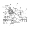
- FIG. 2 is a schematic configuration diagram illustrating a gas turbine combustor according to the first embodiment.
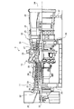
- FIG. 3 is a cross-sectional view of a main part of the gas turbine combustor according to the first embodiment.
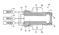
- FIG. 4 is a cross-sectional view illustrating the tip of the pilot nozzle according to the first embodiment.
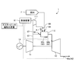
- FIG. 5 is a schematic diagram illustrating a gas turbine according to the first embodiment.
- FIG. 6 is a schematic diagram illustrating a gas turbine according to the second embodiment.
- FIG. 7 is a cross-sectional view illustrating the tip of the pilot nozzle of the third embodiment.
- FIG. 8 is a cross-sectional view illustrating the tip of the pilot nozzle of the fourth embodiment.
- FIG. 9 is a cross-sectional view illustrating the tip of the pilot nozzle of the fifth embodiment.
- FIG. 1 is a schematic configuration diagram illustrating a gas turbine according to a first embodiment.
- FIG. 2 is a schematic configuration diagram illustrating a gas turbine combustor according to the first embodiment.
- FIG. 3 is a cross-sectional view of a main part of the gas turbine combustor according to the first embodiment.
- FIG. 4 is a cross-sectional view illustrating the tip of the pilot nozzle according to the first embodiment.
- FIG. 5 is a schematic diagram illustrating a gas turbine according to the first embodiment.
- the gas turbine 1 of Example 1 is comprised by the compressor 11, the combustor (gas turbine combustor) 12, and the turbine 13, as shown in FIG.1 and FIG.5.
- a generator 14 (see FIG. 5) is connected to the gas turbine 1 so that power generation is possible.
- the compressor 11 has an air intake 20 for taking in air, an inlet guide vane (IGV: Inlet Guide Vane) 22 is disposed in the compressor casing 21, and a plurality of stationary vanes 23 and moving blades 24 are provided. Arranged alternately in the front-rear direction (the axial direction of the rotor 32 to be described later), the bleed chamber 25 is provided on the outside thereof.
- the combustor 12 is combustible by supplying fuel to the compressed air compressed by the compressor 11 and igniting it.
- a plurality of stationary blades 27 and moving blades 28 are alternately disposed in a turbine casing 26 in the front-rear direction (the axial direction of a rotor 32 described later).
- An exhaust chamber 30 is disposed downstream of the turbine casing 26 via an exhaust casing 29, and the exhaust chamber 30 has an exhaust diffuser 31 that is continuous with the turbine 13.
- a rotor (rotary shaft) 32 is positioned so as to penetrate through the center of the compressor 11, the combustor 12, the turbine 13, and the exhaust chamber 30.
- the end of the rotor 32 on the compressor 11 side is rotatably supported by the bearing portion 33, while the end of the exhaust chamber 30 side is rotatably supported by the bearing portion 34.
- the rotor 32 is fixed by stacking a plurality of disks with each blade 24 mounted thereon by the compressor 11 and fixed by a plurality of disks having each blade 28 mounted by the turbine 13.
- the drive shaft of the generator 14 is connected to the end on the compressor 11 side.
- the compressor casing 21 of the compressor 11 is supported by the legs 35
- the turbine casing 26 of the turbine 13 is supported by the legs 36
- the exhaust chamber 30 is supported by the legs 37. Yes.
- the air taken in from the air intake 20 of the compressor 11 passes through the inlet guide vane 22, the plurality of stationary vanes 23 and the moving blade 24 and is compressed to become high-temperature / high-pressure compressed air.
- a predetermined fuel is supplied to the compressed air in the combustor 12 and burned.
- the high-temperature and high-pressure combustion gas that is the working fluid generated in the combustor 12 passes through the plurality of stationary blades 27 and the moving blades 28 constituting the turbine 13 to drive and rotate the rotor 32.
- the generator 14 connected to 32 is driven.
- the combustion gas that has driven the turbine 13 passes through the exhaust diffuser 31 and is discharged from the exhaust chamber 30 to the atmosphere as exhaust gas.
- the casing 41 has a combustor inner cylinder 42 disposed at a predetermined interval on the inner side, and a combustor tail cylinder 43 is disposed at the tip of the combustor inner cylinder 42. It is connected.
- the combustor inner cylinder 42 is located at the center of the inside, and the pilot combustion burner 44 is disposed.
- a plurality of the combustor inner cylinders 42 surround the pilot combustion burner 44 along the circumferential direction on the inner peripheral surface of the combustor inner cylinder 42.
- a main combustion burner 45 is arranged.
- the combustor tail cylinder 43 is connected to a bypass pipe 46, and a bypass valve 47 is provided in the bypass pipe 46.
- a top hat portion 54 is fitted into the casing 41 and fastened by a plurality of fastening bolts 55.
- the combustor inner cylinder 42 is disposed at a predetermined interval inside the casing 41, and a cylindrical air passage 56 is formed between the inner surface of the top hat portion 54 and the outer surface of the combustor inner cylinder 42.
- the air passage 56 has one end communicating with the compressed air supply passage 57 compressed by the compressor 11 and the other end communicating with the base end side of the combustor inner cylinder 42.
- the combustor inner cylinder 42 is formed with a diameter-expanded portion 42a on the base end side, so that the air passage 56 has a bell mouth shape.
- the combustor inner cylinder 42 is located in the center portion, a pilot combustion burner 44 is disposed, and a plurality of main combustion burners 45 are disposed around it.
- the pilot combustion burner 44 includes a pilot cone 58 supported by the combustor inner cylinder 42, and a pilot nozzle 59 disposed inside the pilot cone 58.
- the pilot nozzle 59 includes swirl vanes (swirler vanes) on the outer periphery. ) 60 is provided.
- the main combustion burner 45 is composed of a burner cylinder 61 and a main nozzle 62 disposed inside the burner cylinder 61, and the main nozzle 62 is provided with swirl vanes (swirler vanes) 63 on the outer periphery. .
- the top hat portion 54 is provided with fuel ports 64 and 65, a pilot fuel line (not shown) is connected to the fuel port 64 of the pilot nozzle 59, and a main combustion line (not shown) is connected to the fuel port 65 of each main nozzle 62.
- the top hat portion 54 is provided with a cooling air supply port 66 (see FIG. 5).
- the cooling air supply port 66 is connected to a branch passage (cooling air supply passage) 67 branched from a supply passage 57 from the compressor 11 to the gas turbine combustor 12. That is, the supply passage 57 communicates with the air passage 56 of the gas turbine combustor 12, and the branch passage 67 branched from the supply passage 57 is connected to the cooling air supply port 66 of the gas turbine combustor 12.
- the high-temperature and high-pressure compressed air flows from the supply passage 57 to the air passage 56 and the branch passage 67 and from the air passage 56 into the combustor inner cylinder 42. Then, the air flows into the cooling air supply port 66 from the branch passage 67.
- the compressed air is mixed with the fuel injected from the main combustion burner 45 and flows into the combustor tail cylinder 43 as a swirling flow of premixed air.
- the compressed air is mixed with fuel injected from the pilot combustion burner 44, ignited and burned by a not-shown type fire, and becomes combustion gas in the combustor tail cylinder 43. Erupts.
- a part of the combustion gas is injected into the combustor tail cylinder 43 so as to diffuse to the surroundings with a flame, so that the premixed gas flowing into the combustor tail cylinder 43 from each main combustion burner 45 is obtained. It is ignited and burns. That is, flame holding for stable combustion of the lean premixed fuel from the main combustion burner 45 can be performed from the pilot flame by the pilot fuel injected from the pilot combustion burner 44.
- a high-temperature circulating flow is generated in the pilot cone 58 by burning the main fuel.
- This circulating flow flows in opposition to the front of the pilot nozzle 59.
- the formation position of the circulating flow changes in a direction in which it is in contact with or separated from the pilot nozzle 59 by the cooling air injected from the pilot nozzle 59.
- the compressed air flowing into the cooling air supply port 66 is used as cooling air for cooling the pilot nozzle 59.
- the nozzle body 71 has a hollow cylindrical shape, and a swirl vane 60 is provided around the nozzle body 71.
- the nozzle body 71 has a plurality of internal passages formed therein, and a first fuel passage 72, a second fuel passage 74, and a cooling passage 73 are formed as the plurality of internal passages.
- the second fuel passage 74 is formed at the axial center inside the nozzle body 71 and is formed from the base end side to the tip end side.
- the second fuel passage 74 has a base end communicating with the fuel port 64, and the fuel F supplied from the fuel port 64 is injected from the tip of the nozzle body 71 through the second fuel passage 74.
- the cooling passage 73 is formed on the outer peripheral side of the second fuel passage 74 inside the nozzle body 71 and is formed from the base end side to the tip end side.
- the cooling passage 73 has a base end portion communicating with the cooling air supply port 66, and the compressed air flowing from the compressor 11 into the cooling air supply port 66 through the supply passage 57 and the branch passage 67 is converted into the cooling air A Circulate as
- the first fuel passage 72 is formed on the outer peripheral side of the cooling passage 73 inside the nozzle body 71 and is formed from the base end side of the nozzle body 71 to the inside of the swirl vane 60.
- the first fuel passage 72 communicates with the fuel port 64 on the base end side and with the first fuel injection hole 75 formed in the swirl blade 60 on the tip end side. For this reason, the fuel F supplied from the fuel port 64 passes through the first fuel passage 72 and is injected from the first fuel injection hole 75 formed in the swirl vane 60.
- the cooling passage 73 is provided between the inside of the first fuel passage 72 and the outside of the second fuel passage 74 in the radial direction of the nozzle body 71.
- the fuel F1 flowing through the first fuel passage 72 and the fuel F2 flowing through the second fuel passage 74 contain a fuel gas such as LNG and become an air-fuel mixture (pilot fuel) of the fuel gas and compressed air. Yes.
- the cooling passage 73 is connected to the supply passage 57 through the branch passage 67, and the branch passage 67 is provided with a flow rate adjusting valve (air amount adjusting portion) 77.
- the flow rate adjustment valve 77 is connected to a control device 91 provided in the gas turbine 1. The opening degree of the flow rate adjusting valve 77 is adjusted by the control device 91.
- the tip of the cooling passage 73 communicates with an air injection hole 79 formed at the tip of the nozzle body 71.
- the air injection holes 79 are directed toward the inside of the nozzle body 71 and inject the cooling air A toward the inside of the nozzle body 71 toward the front of the nozzle body 71.
- the tip of the second fuel passage 74 communicates with a second fuel injection hole 78 formed at the tip of the nozzle body 71.
- the second fuel injection hole 78 is directed to the outside of the nozzle body 71 and injects the fuel F ⁇ b> 2 to the outside of the nozzle body 71 toward the front of the nozzle body 71.
- the pilot nozzle 59 can inject the fuel F1 from the first fuel injection hole 75 of the swirl vane 60 and can inject the fuel F2 from the second fuel injection hole 78 of the nozzle body 71. That is, the pilot nozzle 59 can selectively or simultaneously inject the fuel F1 and the fuel F2. Further, the pilot nozzle 59 injects the cooling air A from the air injection hole 79 of the nozzle body 71.
- the base end of the cooling passage 73 is connected to the branch passage 67 via the cooling air supply port 66, and the flow adjustment valve 77 is provided in the branch passage 67.
- the control device 91 controls the flow rate adjusting valve 77 in accordance with the operating state of the gas turbine 1 to adjust the flow rate of the cooling air A flowing through the branch passage 67, thereby injecting from the air injection hole 79. The injection amount of the cooling air A is adjusted.
- the control device 91 increases the opening degree of the flow rate adjusting valve 77 to thereby inject cooling air into the pilot cone 58. Increase the injection amount of A.
- the control device 91 reduces the opening of the flow rate adjusting valve 77 to reduce the cooling air A injected into the pilot cone 58. Reduce the amount of injection. That is, the control device 91 adjusts the opening degree of the flow rate adjustment valve 77 according to the operating state of the gas turbine 1 (the combustion state of the fuel F).
- a detection sensor 92 that detects the operating state of the gas turbine 1 is provided, and the detection sensor 92 is connected to the control device 91.
- the detection sensor 92 include a NOx detection sensor that detects the amount of NOx generated according to the combustion state of the fuel F, and a gas that detects CO or unburned hydrocarbons generated according to the combustion state of the fuel F.
- the control device 91 adjusts the opening degree of the flow rate adjustment valve 77 based on the detection result of the detection sensor 92. Note that the opening degree of the flow rate adjusting valve 77 (that is, the flow rate of the cooling air A) can be adjusted through the control device 91 according to the output state of the gas turbine or the operating state quantity such as the fuel ratio.
- the control device 91 decreases the opening of the flow rate adjusting valve 77 as the pressure fluctuation detected by the pressure sensor 92c increases, and the cooling injection hole 79. The injection quantity of the cooling air A from is reduced.
- the control device 91 increases the opening of the flow rate adjustment valve 77 when the temperature detected by the temperature sensor 92b is larger than a preset temperature. The injection amount of the cooling air A from the cooling injection hole 79 is increased.
- the detection sensor 92 may be any sensor as long as it can detect the operating state of the gas turbine 1, that is, the combustion state of the fuel F.
- (Fuel) F2 is ignited and burned by a seed flame (not shown), and becomes a high-temperature combustion gas and is ejected so as to be diffused around with a flame.
- the cooling air A passing through the cooling passage 73 is jetted to the inside of the nozzle body 71, and the formation position of the circulating flow is adjusted by the cooling air A.
- the control device 91 adjusts the opening degree of the flow rate adjustment valve 77 based on the detection result of the detection sensor 92 and adjusts the injection amount of the cooling air A injected from the air injection hole 79 to the pilot cone 58. . For this reason, when the circulating flow approaches the pilot nozzle 59, the amount of the cooling air A injected from the air injection hole 79 is increased to increase the amount of the circulating flow flowing in front of the pilot nozzle 59 by the increased cooling air A. The formation position can be moved backward.
- the control device 91 can adjust the formation position of the circulation flow by adjusting the flow rate adjustment valve 77.
- the controller 91 adjusts the injection amount of the cooling air A injected from the pilot nozzle 59 by controlling the flow rate adjustment valve 77 based on the detection result of the detection sensor 92. can do. For this reason, the formation position of the circulating flow flowing in front of the pilot nozzle 59 can be adjusted to an appropriate formation position by the flow rate of the cooling air A. Thereby, while suppressing the burning around the pilot nozzle 59 including the pilot nozzle 59, the generation amount of NOx, CO or unburned matter can be suppressed, and the flame holding property can be maintained.
- control device 91 can easily adjust the flow rate of the cooling air A injected from the pilot nozzle 59 by adjusting the opening degree of the flow rate adjusting valve 77.
- the cooling passage 73 can be disposed between the first fuel passage 72 and the second fuel passage 74, the cooling air is provided at the nozzle tip according to the shape of the pilot nozzle 59. A can be input effectively.
- FIG. 7 is a schematic diagram illustrating a gas turbine according to the second embodiment.
- the control device 91 controls the flow rate adjustment valve 77 to adjust the flow rate of the cooling air A flowing through the cooling passage 73.
- a compressor 111 is provided instead of the flow rate adjustment valve 77, and the control device 91 controls the compressor 111 to adjust the flow rate of the cooling air A flowing through the cooling passage 73.
- the cooling passage 73 has a base end connected to the branch passage 67 via the cooling air supply port 66, and the compressor 111 is connected to the branch passage 67.
- the compressor 111 has an inlet side connected to the compressor 11 side and an outlet side connected to the gas turbine combustor 110 side.
- the control device 91 controls the compressor 111 according to the operating state of the gas turbine 1 to adjust the flow rate of the cooling air A flowing through the branch passage 67, thereby cooling the air injected from the air injection holes 79. The injection amount of air A is adjusted.
- the control device 91 sets the rotation speed of the compressor 111 to be high so that the cooling injected to the pilot cone 58 is performed. Increase the injection amount of air A.
- the control device 91 reduces the rotation speed of the compressor 111 to reduce the cooling air injected into the pilot cone 58. The injection amount of A is decreased. That is, the control device 91 adjusts the rotational speed of the compressor 111 according to the operating state of the gas turbine 1 (the combustion state of the fuel F).
- the control device 91 adjusts the flow rate of the cooling air A injected from the pilot nozzle 59 by controlling the compressor 111 based on the detection result of the detection sensor 92. Can do. For this reason, the formation position of the circulating flow flowing in front of the pilot nozzle 59 can be adjusted to an appropriate formation position by the flow rate of the cooling air A. Thereby, while suppressing the burning around the pilot nozzle 59 including the pilot nozzle 59, the generation amount of NOx, CO or unburned matter can be suppressed, and the flame holding property can be maintained.
- the control device 91 can easily adjust the injection amount of the cooling air A injected from the pilot nozzle 59 by controlling the operation of the compressor 111. At this time, the pressure in the cooling passage 73 can be increased as compared with the case where the flow regulating valve 77 is provided in the branch passage 67 as in the first embodiment, so that the injection amount of the cooling air A is adjusted in a wider range. can do.
- the flow rate adjustment valve 77 of the first embodiment is omitted.
- the flow rate adjustment valve 77 may be provided in the branch passage 67 on the downstream side of the compressor 111.
- the control device 91 adjusts the injection amount of the cooling air A by appropriately controlling the flow rate adjusting valve 77 and the compressor 111.
- the first fuel passage 72, the second fuel passage 74, and the cooling passages 73 are provided inside the pilot nozzle 59.
- the present invention is not limited to this configuration, and the fuel F or gas to be used is used.
- a plurality of internal flow paths may be formed as appropriate.
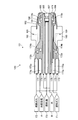
- FIG. 7 is a cross-sectional view illustrating the tip of the pilot nozzle of the third embodiment.
- Example 3 parts different from Examples 1 and 2 will be described in order to avoid redundant descriptions, and parts having the same configurations as those in Examples 1 and 2 will be described with the same reference numerals.
- the pilot nozzle 59 shown in FIG. 4 is applied as the pilot nozzle.
- the pilot nozzle 121 shown in FIG. 7 is applied.
- the pilot nozzle 121 of the third embodiment can selectively or simultaneously inject fuel gases F1, F2 and fuel oil F3 as fuel.
- the fuel port 64 communicating with the pilot nozzle 121 includes a line for supplying the fuel oil F3 and a line for supplying the fuel gases F1 and F2, and the fuel gases F1 and F2 toward the pilot nozzle 121 are provided. And the fuel oil F3 can be supplied.
- the pilot nozzle 121 of Example 3 is demonstrated concretely.
- the pilot nozzle 121 includes a nozzle body 171 and a sleeve 182 provided on the outer periphery of the nozzle body 171 on the tip end side, and is similar to the first embodiment around the nozzle body 171.
- a plurality of swirl vanes 160 are provided side by side at a predetermined interval in the circumferential direction.
- the nozzle body 171 has a hollow cylindrical shape, and a plurality of internal flow paths are formed therein.
- the plurality of internal flow paths include a first fuel gas passage 172, a second fuel gas passage 173, a cooling passage 174, and a fuel oil passage. 175 and a water passage 176 are formed.
- the fuel oil passage 175 is formed at the axial center inside the nozzle body 171 and is formed from the base end side to the tip end side.
- the base end side of the fuel oil passage 175 communicates with the fuel port 64, and the fuel oil F ⁇ b> 3 that has flowed in through the fuel port 64 flows.
- the fuel oil passage 175 communicates with the fuel oil injection part 185 formed at the tip end side of the nozzle body 171 at the tip end side.
- the fuel oil injection unit 185 is formed at the center of the tip of the nozzle body 171 and injects the fuel oil F3 toward the front of the nozzle body 171.
- the water passage 176 is formed in a cylindrical shape along the outer periphery of the fuel oil passage 175 inside the nozzle body 171 and is formed from the base end side to the tip end side.
- the water passage 176 has a base end connected to a water supply source (not shown), and the water W supplied from the water supply source flows therethrough.
- the water passage 176 communicates with the water injection hole 186 formed at the front end of the nozzle body 171 at the front end.
- a plurality of water injection holes 186 are formed side by side at a predetermined interval in the circumferential direction along the outer periphery of the fuel oil injection unit 185 at the tip of the nozzle body 171.
- Each of the plurality of water injection holes 186 is directed toward the inner side (center side) of the nozzle body 171, and jets water W toward the inside of the nozzle body 171 toward the front of the nozzle body 171.
- the cooling passage 174 is formed on the outer peripheral side of the water passage 176 inside the nozzle body 171 and is formed from the base end side to the tip end side.
- the cooling passage 174 has a base end portion communicating with the cooling air supply port 66, and the compressed air flowing from the compressor 11 through the cooling air supply port 66 circulates as the cooling air A.
- the cooling passage 74 communicates with the air injection hole 187 formed at the distal end portion of the nozzle body 171 at the distal end side.
- a plurality of air injection holes 187 are formed at the tip of the nozzle body 171 along the outer periphery of the water injection holes 186 in a circumferential direction with a predetermined interval. Each of the plurality of air injection holes 187 is directed to the inside of the nozzle body 171, and the cooling air A is injected toward the inside of the nozzle body 171 toward the front of the nozzle body 171.
- the first fuel gas passage 173 is formed on the outer peripheral side of the water passage 176 inside the nozzle body 171 and is provided in parallel with the cooling passage 174 in the circumferential direction, from the base end side to the tip end side. It is formed over.
- the base end side communicates with the fuel port 64, and the fuel gas F ⁇ b> 1 that flows through the fuel port 64 flows therethrough.
- the first fuel gas passage 173 communicates with the first fuel gas injection hole 188 formed at the distal end portion of the nozzle body 171 at the distal end side.
- a plurality of first fuel gas injection holes 188 are formed at the tip of the nozzle body 171 along the outer periphery of the air injection holes 187 and arranged at predetermined intervals in the circumferential direction. Each of the plurality of first fuel gas injection holes 188 is directed to the outside of the nozzle body 171, and injects the fuel gas F ⁇ b> 1 toward the outside of the nozzle body 171 toward the front of the nozzle body 171.
- the second fuel gas passage 172 is formed on the outer peripheral side of the cooling passage 174 and the first fuel gas passage 173 inside the nozzle body 171, and is formed from the base end side of the nozzle body 171 to the inside of the swirl vane 160. Yes.
- the base end side communicates with the fuel port 64, and the fuel gas F ⁇ b> 2 that flows in through the fuel port 64 flows.
- the tip end portion of the second fuel gas passage 172 communicates with a plurality of second fuel gas injection holes 189 formed in the plurality of swirl vanes 160.
- the plurality of second fuel gas injection holes 189 inject the fuel gas F ⁇ b> 2 toward the front of the plurality of swirl vanes 160.
- each injection hole (injection part) 185, 186, 187, 188, 189 has different injection directions of fluids such as the fuel gas F1, the fuel gas F2, the fuel oil F3, the cooling air A and the water W. Is formed.
- the sleeve 182 is formed in a cylindrical shape along the outer periphery of the nozzle body 171 and is arranged concentrically with a predetermined gap with respect to the nozzle body 171. That is, the nozzle main body 171 and the sleeve 182 are provided with a predetermined gap by providing a plurality of spacers 191 with a predetermined interval in the circumferential direction therebetween.
- a gap between the nozzle body 171 and the sleeve 182 forms a film air passage (film air passage) 192 through which film air flows.
- the film air passage 192 is formed on the outer periphery of the nozzle body 171 and is formed from the base end side to the tip end side.
- the base end side of the film air passage 192 communicates with an air passage (external flow passage) 56, and a part of the compressed air flowing into the air passage 56 from the compressor 11 through the supply passage 57 is film air.
- Circulate as The film air passage 192 injects film air toward the front of the nozzle body 171 along the outer periphery of the nozzle body 171.
- the second fuel gas passage 172, the first fuel gas passage 173, and the cooling passage 174 are narrowed so that the passage area is reduced. , 173a and 174a are formed.
- the throttle part 172a of the second fuel gas passage 172 has a circular cross section, and a plurality of throttle parts 172a are formed side by side along the circumferential direction of the nozzle body 171 with a predetermined interval (equal intervals).
- the throttle portion 173a of the first fuel gas passage 173 and the throttle portion 174a of the cooling passage 174 have a circular cross section, similar to the throttle portion 172a of the second fuel gas passage 172, and extend in the circumferential direction of the nozzle body 171.
- a plurality of lines are formed side by side at regular intervals (at equal intervals).
- the plurality of throttle portions 173a of the first fuel gas passage 173 and the plurality of throttle portions 174a of the cooling passage 174 are formed on the inner peripheral side of the plurality of throttle portions 172a of the second fuel gas passage 172, and extend along the circumferential direction. Are alternately arranged.
- the plurality of throttle portions 172a, 173a, 174a are provided with the plurality of throttle portions 172a of the second fuel gas passage 172 arranged in the circumferential direction, and the other part of the first fuel gas.
- a plurality of throttle portions 173a and 174a of the passage 173 and the cooling passage 174 are provided side by side in the circumferential direction.
- the plurality of throttle portions 172a that are a part and the plurality of throttle portions 173a and 174a that are the other part are provided concentrically.
- the second fuel gas passage 172, the first fuel gas passage 173, and the cooling passage 174 include manifolds 172b and 173b between the passages and the injection holes. , 174b are formed.
- the manifold 172b of the second fuel gas passage 172 is formed on the tip side of the throttle portion 172a. That is, the manifold 172b of the second fuel gas passage 172 is formed on the downstream side of the throttle portion 172a in the flow direction of the fuel gas F2 flowing through the second fuel gas passage 172.
- the manifold 172b of the second fuel gas passage 172 is formed over the entire circumference of the nozzle body 171 and is formed in an annular shape.
- the manifold 172b communicates with the plurality of throttle portions 172a on the upstream side (base end side), and communicates with the plurality of second fuel gas injection holes 189 on the downstream side (tip end side). Yes.
- the manifold 174b of the cooling passage 174 is formed on the downstream side of the throttle portion 174a in the flow direction of the cooling air A flowing through the cooling passage 174.
- the manifold 174b of the cooling passage 174 is formed over the entire circumference of the nozzle body 171 and is formed in an annular shape.
- the manifold 174b is formed on the inner side of the manifold 172b, and is formed on the tip side of the manifold 172b.
- the manifold 174b communicates with the plurality of throttle portions 174a on the upstream side (base end side), and communicates with the plurality of air injection holes 187 on the downstream side (tip end side).
- the manifold 173b of the first fuel gas passage 173 is formed on the downstream side of the throttle portion 173a in the flow direction of the fuel gas F1 flowing through the first fuel gas passage 173. Similar to the manifold 172b and the manifold 174b, the manifold 173b of the first fuel gas passage 173 is formed over the entire circumference of the nozzle body 171 and is formed in an annular shape. The manifold 173b is formed on the tip side of the manifold 174b. The manifold 173b communicates with the plurality of throttle portions 173a on the upstream side (base end side) and communicates with the plurality of first fuel gas injection holes 188 on the downstream side (tip end side) thereof. .
- the plurality of manifolds 172b, 173b, 174b are arranged in order from the base end side of the nozzle body 171 to the tip end side, the manifold 172b of the second fuel gas passage 172, the manifold 174b of the cooling passage 174, the first A manifold 173b of the fuel gas passage 173 is formed.
- the plurality of manifolds 172b, 173b, and 174b are formed in different positions in the direction connecting the base end side and the tip end side of the nozzle body 171.
- the water W that has flowed into the water passage 176 from the water supply source flows through the water passage 176 and passes through the water injection holes 186 formed around the fuel oil injection portion 185 of the nozzle body 171 to the front of the nozzle body 171. Toward the inside of the nozzle body 171.
- the film air that has flowed into the film air passage 192 from the air passage 56 flows through the film air passage 192 and is jetted toward the front of the nozzle body 171 along the outer periphery of the nozzle body 171.
- the second fuel gas passage 172, the first fuel gas passage 173, the cooling passage 174, the fuel oil passage 175, and the water passage 176 which are a plurality of internal passages of the nozzle body 171. Accordingly, the fuel gas F1, the fuel gas F2, the fuel oil F3, the cooling air A, and the water W, which are fluids, can be circulated without being mixed.
- the fuel gas F1, the fuel gas F2, and the cooling air A that circulate through the second fuel gas passage 172, the first fuel gas passage 173, and the cooling passage 174 pass through the throttle portions 172a, 173a, and 174a, so Therefore, the amount of fuel injected from the second fuel gas injection hole 189, the first fuel gas injection hole 188, and the air injection hole 187 can be stabilized.
- the fuel gas F1, the fuel gas F2, and the cooling air A that have circulated through the throttle portions 172a, 173a, and 174a circulate through the manifolds 172b, 173b, and 174b and the second fuel gas injection hole 189.
- the first fuel gas injection hole 188 and the air injection hole 187 are injected. Therefore, the fuel gas F1, the fuel gas F2, and the cooling air A injected from the second fuel gas injection hole 189, the first fuel gas injection hole 188, and the air injection hole 187 via the manifolds 172b, 173b, and 174b are It is possible to inject at a uniform pressure in the direction.
- the plurality of manifolds 172b, 173b, and 174b can be formed in a position shifted in the direction connecting the base end side and the tip end side of the nozzle body 171, a plurality of manifolds are formed. 172b, 173b, and 174b are not formed overlapping in the radial direction of the nozzle body 171 and the nozzle body 171 can be made compact.
- the injection holes (injection units) 185, 186 are arranged so that the injection directions of fluids such as the fuel gas F1, the fuel gas F2, the fuel oil F3, the cooling air A, and the water W are different. Since 187, 188, and 189 can be formed, the ejection shape of the fluid can be an arbitrary shape.
- the plurality of throttle portions 172a, 173a, 174a can be arranged in the circumferential direction and arranged concentrically, so that the plurality of throttle portions 172a, 173a, 174a do not cross each other. Can be arranged.
- the fuel oil F3 is burned to generate combustion gas.
- the fuel gas F1, F2 can be burned to generate combustion gas, or the nozzle body 71 can be cooled by the water W and the cooling air A. For this reason, it can be set as a highly versatile pilot nozzle.
- the pilot nozzle 121 mixes the fuel gas F1, the fuel gas F2, the fuel oil F3, the cooling air A, and the water W flowing through the passages 172, 173, 174, 175, and 176. Without injecting, it can inject from each injection hole (injection part) 185, 186, 187, 188, 189 in the state where it injected with uniform pressure and the injection quantity was stabilized. For this reason, it becomes possible to perform combustion of the pilot nozzle 121 stably. Thereby, since it becomes possible to perform combustion by the gas turbine combustor 12 stably, the improvement of the turbine efficiency by stable combustion can be aimed at.
- the second fuel gas passage 172, the first fuel gas passage 173, the cooling passage 174, the fuel oil passage 175, and the water passage 176 are formed as the plurality of internal passages. Instead, a passage through which another fluid flows may be formed, or a configuration in which a part of the passage is omitted may be employed.
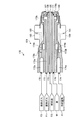
- FIG. 8 is a cross-sectional view illustrating the tip of the pilot nozzle of the fourth embodiment.
- the water passage 176 is formed in a cylindrical shape along the outer periphery of the fuel oil passage 175.
- the water passage 176 is formed on the outer peripheral side of the fuel oil passage 175. Forming.
- the pilot nozzle 131 of the fourth embodiment has a hollow cylindrical shape as in the third embodiment, and a swirl vane 160 is provided around the nozzle main body 171.
- the nozzle body 171 is formed with a fuel oil passage 175, a first fuel gas passage 173, a water passage 176, a second fuel gas passage 172, and a cooling passage 174 in order from the inside (center side) to the outside.
- the fuel oil passage 175 is substantially the same as that of the first embodiment, and a description thereof will be omitted.
- the first fuel gas passage 173 is formed on the outer peripheral side of the fuel oil passage 175 inside the nozzle main body 171, and the water passage 176 is also formed on the outer peripheral side of the fuel oil passage 175 inside the nozzle main body 171.
- the first fuel gas passage 173 and the water passage 176 are provided in parallel along the circumferential direction of the nozzle body 171.
- the second fuel gas passage 172 is formed on the outer peripheral side of the first fuel gas passage 173 and the water passage 176 inside the nozzle body 171, and the cooling passage 174 is also connected to the first fuel gas passage 173 and the water inside the nozzle body 171. It is formed on the outer peripheral side of the passage 176.
- the second fuel gas passage 172 and the cooling passage 174 are provided in parallel along the circumferential direction of the nozzle body 171.
- the throttle portions 172a, 173a, 174a and the manifolds 172b, 173b, and the second fuel gas passage 172, the first fuel gas passage 173, and the cooling passage 174 are provided.
- 174b is formed.
- the throttle portions 172a, 173a, 174a and the manifolds 172b, 173b, 174b are the same as those in the third embodiment, and thus the description thereof is omitted.
- a manifold 176 b is formed in the water passage 176 in the pilot nozzle 131 of the fourth embodiment.
- the manifold 176b of the water passage 76 is formed closer to the tip end side of the nozzle body 171 than the other manifolds 172b, 173b, 174b.
- the manifold 176b of the water passage 176 is formed over the entire circumference of the nozzle body 171 and is formed in an annular shape. As shown in FIG. 8, the manifold 176b is formed on the inner side of the manifold 174b and on the tip side of the manifold 174b.
- the manifold 176b communicates with the plurality of water injection holes 186 on the downstream side (tip end side).
- the plurality of internal channels can be arranged in a different arrangement pattern from the first embodiment.
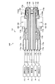
- FIG. 9 is a cross-sectional view illustrating the tip of the pilot nozzle of the fifth embodiment.
- the film air passage 192 is formed so as to communicate with the air passage 56 that is an external flow path outside the nozzle body 171.
- the film air passage 192 is used as the internal flow passage of the nozzle body 142.
- the film air passage 192 serving as an external flow path is used as the internal flow path.
- the nozzle body 142 of the pilot nozzle 131 has a plurality of internal flow paths formed therein, and the first fuel gas passage 172 and the second fuel gas passage are provided as the plurality of internal flow paths. 173, a cooling passage (cooling passage) 174A, a film air passage (film air passage) 174B, a fuel oil passage 175, and a water passage 176 are formed.
- the first fuel gas passage 172, the second fuel gas passage 173, the fuel oil passage 175, and the water passage 176 are the same as those in the third embodiment, and thus description thereof is omitted.
- the sleeve 182 of the third embodiment is omitted (in other words, integrated with the nozzle body 142).
- the cooling passage 174A and the film air passage 174B are respectively branched from the manifold 174b in the cooling passage 174 of the third embodiment. That is, the cooling passage 174A is a passage through which the cooling air passes through the throttle portion 174a and the manifold 174b in the cooling passage 174 of the third embodiment and travels toward the air injection hole 187.
- the film air passage 174 ⁇ / b> B is a flow path that goes to the film air passage 192 of the third embodiment through the throttle portion 174 a and the manifold 174 b in the cooling passage 174 of the third embodiment as film air. Yes. That is, the film air passage 192 of the third embodiment constitutes a part (tip portion) of the film air passage 174B of the fifth embodiment.
- a cooling air manifold 174Ab is provided between the manifold 174b and the air injection hole 187.
- the cooling air manifold 174Ab is formed over the entire circumference of the nozzle body 142 and is formed in an annular shape.
- the cooling air manifold 174Ab is formed on the inner side of the film air passage 192 on the front end side and on the outer side of the manifold 173b, and is formed on the front end side of the film air manifold 174Bb described later.
- the cooling air manifold 174Ab communicates with the manifold 174b on the upstream side (base end side), and communicates with the plurality of air injection holes 187 on the downstream side (tip end side).
- the film air passage 174B is provided with a film air manifold 174Bb between the manifold 174b and the film air passage 192 on the front end side.
- the film air manifold 174Bb is formed over the entire circumference of the nozzle body 142 and is formed in an annular shape.
- the film air manifold 174Bb is formed on the outermost side, and is formed on the base end side of the cooling air manifold 174Ab.
- the film air manifold 174Bb communicates with the manifold 174b on the upstream side (base end side) and communicates with the film air passage 192 on the distal end side on the downstream side (tip end side).
- the cooling passage 174A and the film air passage 174B formed in this way are arranged on the same circumference as the first fuel gas passage 173.
- the cooling passage 174A and the film air passage 174B are round holes with a circular cross section, and the first fuel gas passage 173 is a long hole with an oval cross section (for example, an oval shape).
- a plurality of cooling passages 174A and film air passages 174B on the distal end side of the manifold 174b are formed in the circumferential direction, and a plurality of first fuel gas passages 173 on the proximal end side of the manifold 173b are formed in the circumferential direction.
- the plurality of cooling passages 174A and the film air passages 174B and the plurality of first fuel gas passages 173 are alternately arranged along the circumferential direction.
- the plurality of cooling passages 174A and the plurality of film air passages 174B are alternately arranged along the circumferential direction.
- the cooling air A flowing into the cooling passage 174 from the cooling air supply port 66 flows through the throttle portion 174a, so that the flow amount of the cooling air A toward the tip side becomes stable. Thereafter, the cooling air A flows through the entire circumference of the nozzle body 142 by flowing through the manifold 174b. A part of the cooling air A flowing through the manifold 174b flows into the cooling passage 174A, and the remaining part flows into the film air passage 174B. The cooling air A flowing into the cooling passage 174A flows through the entire circumference of the nozzle body 142 by flowing through the cooling air manifold 174Ab.
- the cooling air A flowing through the cooling air manifold 174Ab is injected toward the inside of the nozzle body 142 from the plurality of air injection holes 187 toward the front of the nozzle body 142.
- the cooling air A flowing into the film air passage 174B flows through the entire circumference of the nozzle body 142 by flowing through the film air manifold 174Bb.
- the cooling air A flowing through the film air manifold 174Bb is jetted from the film air passage 192 on the front end side toward the front of the nozzle body 142.
- the plurality of internal flow paths can be arranged differently from the first to fourth embodiments. That is, the fuel oil passage 175, the water passage 176, the first fuel gas passage 173, the second fuel gas passage 172, the cooling passage 174 ⁇ / b> A and the film air passage 174 ⁇ / b> B can be a plurality of internal passages of the nozzle body 142.
- the present invention is applied to the pilot nozzles 59, 121, 131, and 141, but is not particularly limited as long as it is an injection nozzle that can inject cooling air toward the circulation flow.
- the main nozzle 62 may be applied.
Landscapes
- Engineering & Computer Science (AREA)
- Chemical & Material Sciences (AREA)
- Combustion & Propulsion (AREA)
- Mechanical Engineering (AREA)
- General Engineering & Computer Science (AREA)
- Turbine Rotor Nozzle Sealing (AREA)
Priority Applications (4)
| Application Number | Priority Date | Filing Date | Title |
|---|---|---|---|
| US15/129,947 US10718522B2 (en) | 2014-04-30 | 2014-09-03 | Gas turbine combustor, gas turbine, control device, and control method |
| DE112014006633.8T DE112014006633T5 (de) | 2014-04-30 | 2014-09-03 | Gasturbinenbrennkammer, Gasturbine, Steuervorrichtung und Steuerverfahren |
| CN201480077592.5A CN106133294B (zh) | 2014-04-30 | 2014-09-03 | 燃气涡轮燃烧器、燃气涡轮、控制装置以及控制方法 |
| KR1020167026979A KR101792453B1 (ko) | 2014-04-30 | 2014-09-03 | 가스 터빈 연소기, 가스 터빈, 제어 장치 및 제어 방법 |
Applications Claiming Priority (2)
| Application Number | Priority Date | Filing Date | Title |
|---|---|---|---|
| JP2014-094029 | 2014-04-30 | ||
| JP2014094029A JP6177187B2 (ja) | 2014-04-30 | 2014-04-30 | ガスタービン燃焼器、ガスタービン、制御装置及び制御方法 |
Publications (1)
| Publication Number | Publication Date |
|---|---|
| WO2015166597A1 true WO2015166597A1 (ja) | 2015-11-05 |
Family
ID=54358345
Family Applications (1)
| Application Number | Title | Priority Date | Filing Date |
|---|---|---|---|
| PCT/JP2014/073253 Ceased WO2015166597A1 (ja) | 2014-04-30 | 2014-09-03 | ガスタービン燃焼器、ガスタービン、制御装置及び制御方法 |
Country Status (6)
| Country | Link |
|---|---|
| US (1) | US10718522B2 (enExample) |
| JP (1) | JP6177187B2 (enExample) |
| KR (1) | KR101792453B1 (enExample) |
| CN (1) | CN106133294B (enExample) |
| DE (1) | DE112014006633T5 (enExample) |
| WO (1) | WO2015166597A1 (enExample) |
Families Citing this family (25)
| Publication number | Priority date | Publication date | Assignee | Title |
|---|---|---|---|---|
| US10215412B2 (en) * | 2012-11-02 | 2019-02-26 | General Electric Company | System and method for load control with diffusion combustion in a stoichiometric exhaust gas recirculation gas turbine system |
| JP6430756B2 (ja) | 2014-09-19 | 2018-11-28 | 三菱日立パワーシステムズ株式会社 | 燃焼バーナ及び燃焼器、並びにガスタービン |
| JP5913503B2 (ja) | 2014-09-19 | 2016-04-27 | 三菱重工業株式会社 | 燃焼バーナ及び燃焼器、並びにガスタービン |
| US10012387B2 (en) * | 2014-12-05 | 2018-07-03 | General Electric Company | Fuel supply system for a gas turbine engine |
| JP6026028B1 (ja) * | 2016-03-10 | 2016-11-16 | 三菱日立パワーシステムズ株式会社 | 燃焼器用パネル、燃焼器、燃焼装置、ガスタービン、及び燃焼器用パネルの冷却方法 |
| US10690350B2 (en) * | 2016-11-28 | 2020-06-23 | General Electric Company | Combustor with axially staged fuel injection |
| US11156362B2 (en) | 2016-11-28 | 2021-10-26 | General Electric Company | Combustor with axially staged fuel injection |
| JP6634658B2 (ja) * | 2016-12-20 | 2020-01-22 | 三菱重工業株式会社 | メインノズル、燃焼器及びメインノズルの製造方法 |
| DE102017101161A1 (de) * | 2017-01-23 | 2018-07-26 | Man Diesel & Turbo Se | Gasturbine |
| KR101953963B1 (ko) | 2017-01-24 | 2019-03-04 | 두산중공업 주식회사 | 가스터빈 |
| US20190107059A1 (en) * | 2017-10-10 | 2019-04-11 | United Technologies Corporation | Cooled combustor configuration |
| CN108916912A (zh) * | 2018-05-08 | 2018-11-30 | 北京航空航天大学 | 一种预燃级采用冷却防积碳结构的低排放燃烧室头部 |
| CN109028143B (zh) * | 2018-06-20 | 2021-03-05 | 中国科学院工程热物理研究所 | 抑制燃烧不稳定的燃料供应装置、燃烧设备及控制方法 |
| EP3657074B1 (en) * | 2018-11-26 | 2021-06-23 | Ansaldo Energia Switzerland AG | Method for manufacturing a burner lance |
| JP7274876B2 (ja) * | 2019-01-25 | 2023-05-17 | 三菱重工業株式会社 | 固体燃料粉砕装置及びこれを備えた発電プラント並びに固体燃料粉砕装置の制御方法 |
| US11774093B2 (en) * | 2020-04-08 | 2023-10-03 | General Electric Company | Burner cooling structures |
| US11460191B2 (en) | 2020-08-31 | 2022-10-04 | General Electric Company | Cooling insert for a turbomachine |
| US11994293B2 (en) | 2020-08-31 | 2024-05-28 | General Electric Company | Impingement cooling apparatus support structure and method of manufacture |
| US11371702B2 (en) | 2020-08-31 | 2022-06-28 | General Electric Company | Impingement panel for a turbomachine |
| US11994292B2 (en) | 2020-08-31 | 2024-05-28 | General Electric Company | Impingement cooling apparatus for turbomachine |
| US11614233B2 (en) | 2020-08-31 | 2023-03-28 | General Electric Company | Impingement panel support structure and method of manufacture |
| JP2022049136A (ja) * | 2020-09-16 | 2022-03-29 | 三菱重工業株式会社 | 燃料ノズルおよびガスタービン燃焼器 |
| US11255545B1 (en) | 2020-10-26 | 2022-02-22 | General Electric Company | Integrated combustion nozzle having a unified head end |
| US11767766B1 (en) | 2022-07-29 | 2023-09-26 | General Electric Company | Turbomachine airfoil having impingement cooling passages |
| WO2024257547A1 (ja) * | 2023-06-13 | 2024-12-19 | 三菱重工業株式会社 | ガスタービン燃焼器及びガスタービン |
Citations (5)
| Publication number | Priority date | Publication date | Assignee | Title |
|---|---|---|---|---|
| JPH0874604A (ja) * | 1994-09-12 | 1996-03-19 | Hitachi Ltd | 液体燃料の燃焼方法及び燃焼装置 |
| JP2004101071A (ja) * | 2002-09-10 | 2004-04-02 | Mitsubishi Heavy Ind Ltd | 燃焼器 |
| JP2004138376A (ja) * | 2002-08-22 | 2004-05-13 | Hitachi Ltd | ガスタービン燃焼器及びガスタービン燃焼器の燃焼方法並びにガスタービン燃焼器の改造方法 |
| JP2011099654A (ja) * | 2009-11-09 | 2011-05-19 | Mitsubishi Heavy Ind Ltd | ガスタービン用燃焼バーナ |
| JP2013096324A (ja) * | 2011-11-02 | 2013-05-20 | Kawasaki Heavy Ind Ltd | ガスタービンシステム |
Family Cites Families (31)
| Publication number | Priority date | Publication date | Assignee | Title |
|---|---|---|---|---|
| US2715816A (en) * | 1950-10-27 | 1955-08-23 | Ruston & Hornsby Ltd | Combustion chamber for use with internal combustion turbines |
| US3952501A (en) * | 1971-04-15 | 1976-04-27 | United Aircraft Of Canada Limited | Gas turbine control |
| US4044549A (en) * | 1972-12-11 | 1977-08-30 | Zwick Eugene B | Low emission combustion process and apparatus |
| JPS5129726A (enExample) * | 1974-09-06 | 1976-03-13 | Mitsubishi Heavy Ind Ltd | |
| JP2894861B2 (ja) * | 1991-04-18 | 1999-05-24 | 株式会社日立製作所 | ガスタービン燃焼器の制御装置 |
| JP2954401B2 (ja) * | 1991-08-23 | 1999-09-27 | 株式会社日立製作所 | ガスタービン設備およびその運転方法 |
| JPH0579629A (ja) * | 1991-09-19 | 1993-03-30 | Hitachi Ltd | 燃焼器およびその運転方法 |
| US5259184A (en) * | 1992-03-30 | 1993-11-09 | General Electric Company | Dry low NOx single stage dual mode combustor construction for a gas turbine |
| DE4411623A1 (de) * | 1994-04-02 | 1995-10-05 | Abb Management Ag | Vormischbrenner |
| DE4411622A1 (de) * | 1994-04-02 | 1995-10-05 | Abb Management Ag | Vormischbrenner |
| JP3619626B2 (ja) * | 1996-11-29 | 2005-02-09 | 株式会社東芝 | ガスタービン燃焼器の運転方法 |
| EP0935097B1 (en) * | 1998-02-09 | 2004-09-01 | Mitsubishi Heavy Industries, Ltd. | Combustor |
| AU776725B2 (en) * | 2000-08-04 | 2004-09-16 | Mitsubishi Hitachi Power Systems, Ltd. | Solid fuel burner and combustion method using solid fuel burner |
| US6928823B2 (en) * | 2001-08-29 | 2005-08-16 | Hitachi, Ltd. | Gas turbine combustor and operating method thereof |
| JP4134311B2 (ja) * | 2002-03-08 | 2008-08-20 | 独立行政法人 宇宙航空研究開発機構 | ガスタービン燃焼器 |
| US7143583B2 (en) | 2002-08-22 | 2006-12-05 | Hitachi, Ltd. | Gas turbine combustor, combustion method of the gas turbine combustor, and method of remodeling a gas turbine combustor |
| GB2405197B (en) * | 2003-08-16 | 2005-09-28 | Rolls Royce Plc | Fuel injector |
| RU2407950C2 (ru) * | 2003-09-05 | 2010-12-27 | Делэвэн Инк | Горелка для камеры сгорания газовой турбины (варианты) |
| JP4728176B2 (ja) * | 2005-06-24 | 2011-07-20 | 株式会社日立製作所 | バーナ、ガスタービン燃焼器及びバーナの冷却方法 |
| JP5055144B2 (ja) | 2008-01-18 | 2012-10-24 | 三菱重工業株式会社 | パイロットノズル、ガスタービン燃焼器およびガスタービン |
| US8479519B2 (en) | 2009-01-07 | 2013-07-09 | General Electric Company | Method and apparatus to facilitate cooling of a diffusion tip within a gas turbine engine |
| US20110005189A1 (en) * | 2009-07-08 | 2011-01-13 | General Electric Company | Active Control of Flame Holding and Flashback in Turbine Combustor Fuel Nozzle |
| JP5159741B2 (ja) * | 2009-09-30 | 2013-03-13 | 株式会社日立製作所 | ガスタービン燃焼器の制御装置およびガスタービン燃焼器の制御方法 |
| WO2012057282A1 (ja) * | 2010-10-28 | 2012-05-03 | 三菱重工業株式会社 | ガスタービンおよびこれを備えたガスタービンプラント |
| WO2012133774A1 (ja) * | 2011-03-30 | 2012-10-04 | 三菱重工業株式会社 | ノズル及びガスタービン燃焼器、ガスタービン |
| JP5773342B2 (ja) * | 2011-06-03 | 2015-09-02 | 川崎重工業株式会社 | 燃料噴射装置 |
| US9957891B2 (en) * | 2011-09-09 | 2018-05-01 | General Electric Company | Fuel manifold cooling flow recirculation |
| US9003806B2 (en) * | 2012-03-05 | 2015-04-14 | General Electric Company | Method of operating a combustor from a liquid fuel to a gas fuel operation |
| US20140157785A1 (en) * | 2012-12-06 | 2014-06-12 | General Electric Company | Fuel supply system for gas turbine |
| CN105164471B (zh) * | 2013-03-13 | 2017-09-08 | 工业涡轮(英国)有限公司 | 贫方位角火焰燃烧器 |
| US9587834B2 (en) * | 2014-02-13 | 2017-03-07 | Siemens Energy, Inc. | Flashback detection in gas turbine engines using distributed sensing |
-
2014
- 2014-04-30 JP JP2014094029A patent/JP6177187B2/ja active Active
- 2014-09-03 CN CN201480077592.5A patent/CN106133294B/zh active Active
- 2014-09-03 US US15/129,947 patent/US10718522B2/en active Active
- 2014-09-03 KR KR1020167026979A patent/KR101792453B1/ko active Active
- 2014-09-03 WO PCT/JP2014/073253 patent/WO2015166597A1/ja not_active Ceased
- 2014-09-03 DE DE112014006633.8T patent/DE112014006633T5/de active Pending
Patent Citations (5)
| Publication number | Priority date | Publication date | Assignee | Title |
|---|---|---|---|---|
| JPH0874604A (ja) * | 1994-09-12 | 1996-03-19 | Hitachi Ltd | 液体燃料の燃焼方法及び燃焼装置 |
| JP2004138376A (ja) * | 2002-08-22 | 2004-05-13 | Hitachi Ltd | ガスタービン燃焼器及びガスタービン燃焼器の燃焼方法並びにガスタービン燃焼器の改造方法 |
| JP2004101071A (ja) * | 2002-09-10 | 2004-04-02 | Mitsubishi Heavy Ind Ltd | 燃焼器 |
| JP2011099654A (ja) * | 2009-11-09 | 2011-05-19 | Mitsubishi Heavy Ind Ltd | ガスタービン用燃焼バーナ |
| JP2013096324A (ja) * | 2011-11-02 | 2013-05-20 | Kawasaki Heavy Ind Ltd | ガスタービンシステム |
Also Published As
| Publication number | Publication date |
|---|---|
| KR20160128375A (ko) | 2016-11-07 |
| US20170219211A1 (en) | 2017-08-03 |
| US10718522B2 (en) | 2020-07-21 |
| JP6177187B2 (ja) | 2017-08-09 |
| CN106133294B (zh) | 2018-01-09 |
| JP2015209842A (ja) | 2015-11-24 |
| DE112014006633T5 (de) | 2017-02-09 |
| KR101792453B1 (ko) | 2017-11-01 |
| CN106133294A (zh) | 2016-11-16 |
Similar Documents
| Publication | Publication Date | Title |
|---|---|---|
| JP6177187B2 (ja) | ガスタービン燃焼器、ガスタービン、制御装置及び制御方法 | |
| JP5611450B2 (ja) | ノズル及びガスタービン燃焼器、ガスタービン | |
| JP6626743B2 (ja) | 燃焼装置及びガスタービン | |
| JP6012407B2 (ja) | ガスタービン燃焼器及びガスタービン | |
| JP2013140003A (ja) | タービンエンジン及びタービンエンジンにおいて空気を流す方法 | |
| CN109072782B (zh) | 燃烧器及燃气轮机 | |
| JP6236149B2 (ja) | ガスタービン燃焼器及びガスタービン | |
| JP2014092286A5 (enExample) | ||
| GB2585025A (en) | Combustor for a gas turbine | |
| US12398886B2 (en) | Combustor for a gas turbine | |
| JP6452298B2 (ja) | 噴射ノズル、ガスタービン燃焼器及びガスタービン | |
| JP6297262B2 (ja) | ノズル及びガスタービン燃焼器、ガスタービン | |
| CN102356279A (zh) | 尤其用于燃气轮机的燃烧器的工作方法和燃烧器 | |
| JP7285623B2 (ja) | ガスタービン燃焼器及びそれを備えるガスタービン、並びに、ガスタービン燃焼器の燃焼振動抑制方法 | |
| JP7193962B2 (ja) | 燃焼器及びこれを備えたガスタービン | |
| JP6037812B2 (ja) | 燃料ノズル、燃焼バーナ、ガスタービン燃焼器及びガスタービン | |
| KR102164621B1 (ko) | 연료 노즐 어셈블리 및 이를 포함하는 가스 터빈용 연소기 | |
| WO2024116966A1 (ja) | ガスタービンの運転方法 | |
| JP6832137B2 (ja) | ガスタービン |
Legal Events
| Date | Code | Title | Description |
|---|---|---|---|
| 121 | Ep: the epo has been informed by wipo that ep was designated in this application |
Ref document number: 14890715 Country of ref document: EP Kind code of ref document: A1 |
|
| ENP | Entry into the national phase |
Ref document number: 20167026979 Country of ref document: KR Kind code of ref document: A |
|
| WWE | Wipo information: entry into national phase |
Ref document number: 15129947 Country of ref document: US |
|
| WWE | Wipo information: entry into national phase |
Ref document number: 112014006633 Country of ref document: DE |
|
| 122 | Ep: pct application non-entry in european phase |
Ref document number: 14890715 Country of ref document: EP Kind code of ref document: A1 |