WO2015163045A1 - 正極材料、ペースト及びナトリウムイオン電池 - Google Patents
正極材料、ペースト及びナトリウムイオン電池 Download PDFInfo
- Publication number
- WO2015163045A1 WO2015163045A1 PCT/JP2015/057990 JP2015057990W WO2015163045A1 WO 2015163045 A1 WO2015163045 A1 WO 2015163045A1 JP 2015057990 W JP2015057990 W JP 2015057990W WO 2015163045 A1 WO2015163045 A1 WO 2015163045A1
- Authority
- WO
- WIPO (PCT)
- Prior art keywords
- positive electrode
- carbonaceous
- particles
- active material
- electrode active
- Prior art date
- Legal status (The legal status is an assumption and is not a legal conclusion. Google has not performed a legal analysis and makes no representation as to the accuracy of the status listed.)
- Ceased
Links
Classifications
-
- H—ELECTRICITY
- H01—ELECTRIC ELEMENTS
- H01M—PROCESSES OR MEANS, e.g. BATTERIES, FOR THE DIRECT CONVERSION OF CHEMICAL ENERGY INTO ELECTRICAL ENERGY
- H01M10/00—Secondary cells; Manufacture thereof
- H01M10/05—Accumulators with non-aqueous electrolyte
- H01M10/054—Accumulators with insertion or intercalation of metals other than lithium, e.g. with magnesium or aluminium
-
- H—ELECTRICITY
- H01—ELECTRIC ELEMENTS
- H01M—PROCESSES OR MEANS, e.g. BATTERIES, FOR THE DIRECT CONVERSION OF CHEMICAL ENERGY INTO ELECTRICAL ENERGY
- H01M4/00—Electrodes
- H01M4/02—Electrodes composed of, or comprising, active material
- H01M4/13—Electrodes for accumulators with non-aqueous electrolyte, e.g. for lithium-accumulators; Processes of manufacture thereof
- H01M4/136—Electrodes based on inorganic compounds other than oxides or hydroxides, e.g. sulfides, selenides, tellurides, halogenides or LiCoFy
-
- H—ELECTRICITY
- H01—ELECTRIC ELEMENTS
- H01M—PROCESSES OR MEANS, e.g. BATTERIES, FOR THE DIRECT CONVERSION OF CHEMICAL ENERGY INTO ELECTRICAL ENERGY
- H01M4/00—Electrodes
- H01M4/02—Electrodes composed of, or comprising, active material
- H01M4/13—Electrodes for accumulators with non-aqueous electrolyte, e.g. for lithium-accumulators; Processes of manufacture thereof
- H01M4/139—Processes of manufacture
- H01M4/1397—Processes of manufacture of electrodes based on inorganic compounds other than oxides or hydroxides, e.g. sulfides, selenides, tellurides, halogenides or LiCoFy
-
- H—ELECTRICITY
- H01—ELECTRIC ELEMENTS
- H01M—PROCESSES OR MEANS, e.g. BATTERIES, FOR THE DIRECT CONVERSION OF CHEMICAL ENERGY INTO ELECTRICAL ENERGY
- H01M4/00—Electrodes
- H01M4/02—Electrodes composed of, or comprising, active material
- H01M4/36—Selection of substances as active materials, active masses, active liquids
-
- H—ELECTRICITY
- H01—ELECTRIC ELEMENTS
- H01M—PROCESSES OR MEANS, e.g. BATTERIES, FOR THE DIRECT CONVERSION OF CHEMICAL ENERGY INTO ELECTRICAL ENERGY
- H01M4/00—Electrodes
- H01M4/02—Electrodes composed of, or comprising, active material
- H01M4/36—Selection of substances as active materials, active masses, active liquids
- H01M4/58—Selection of substances as active materials, active masses, active liquids of inorganic compounds other than oxides or hydroxides, e.g. sulfides, selenides, tellurides, halogenides or LiCoFy; of polyanionic structures, e.g. phosphates, silicates or borates
-
- Y—GENERAL TAGGING OF NEW TECHNOLOGICAL DEVELOPMENTS; GENERAL TAGGING OF CROSS-SECTIONAL TECHNOLOGIES SPANNING OVER SEVERAL SECTIONS OF THE IPC; TECHNICAL SUBJECTS COVERED BY FORMER USPC CROSS-REFERENCE ART COLLECTIONS [XRACs] AND DIGESTS
- Y02—TECHNOLOGIES OR APPLICATIONS FOR MITIGATION OR ADAPTATION AGAINST CLIMATE CHANGE
- Y02E—REDUCTION OF GREENHOUSE GAS [GHG] EMISSIONS, RELATED TO ENERGY GENERATION, TRANSMISSION OR DISTRIBUTION
- Y02E60/00—Enabling technologies; Technologies with a potential or indirect contribution to GHG emissions mitigation
- Y02E60/10—Energy storage using batteries
Definitions
- the present invention relates to a positive electrode material, a paste, and a sodium ion battery.
- This application claims priority based on Japanese Patent Application No. 2014-91866 for which it applied to Japan on April 25, 2014, and uses the content here.
- a positive electrode active material Na 2 M 2 (SO 4 ) 3 (where M is a transition metal element such as Fe, Mn, Co, Ni)) containing a sulfate compound has been proposed (for example, see Non-Patent Document 1).
- This positive electrode active material differs from the conventional monoclinic structure or Nasicon type sodium sulfate compound, when used as a positive electrode material, 3.6 V vs. A discharge reaction occurs when the Na content is exceeded.
- it is a low-cost material composed of abundant elements such as Na, Fe, S, and O, it is expected as a very promising material as a positive electrode active material for sodium ion batteries.
- a positive electrode active material containing a sodium sulfate compound having a novel crystal structure has a low electronic conductivity and has a problem in solubility in water. Therefore, in order to improve battery characteristics such as discharge capacity and cycle characteristics at a high-speed charge / discharge rate, it is necessary to uniformly coat the surface of sodium sulfate compound particles with a carbonaceous material. Conventionally, the surface of positive electrode active material particles is uniformly coated with a carbonaceous material by pyrolysis of organic matter. However, since the positive electrode active material containing sodium sulfate compound has low thermal stability, It is necessary to coat the carbonaceous material.
- the present invention has been made in view of the above circumstances, and provides a positive electrode material, a paste, and a sodium ion battery that are excellent in water resistance, have high electron conductivity, and are suitably used for sodium ion secondary batteries. Objective.
- the positive electrode material of the present invention has a Na x M y (SO 4 ) y (where M is the M 2 O 10 dimer crystal structure in which two MO 6 in the structure share a ridge to form a dimer).
- M is the M 2 O 10 dimer crystal structure in which two MO 6 in the structure share a ridge to form a dimer.
- the paste of the present invention is characterized by containing the positive electrode material of the present invention, a conductive auxiliary agent, and a binder.
- the sodium ion battery of the present invention comprises an electrode plate having a positive electrode formed on one main surface of a current collector using the paste of the present invention.
- Na x M y (SO 4 ) having two M 2 MO 6 were formed edge-sharing to dimers O 10 dimeric crystal structure in the structure represented by y
- the coverage of the carbonaceous film on the surface of the primary particles of the positive electrode active material particles containing the sodium sulfate compound is high. Therefore, since it is excellent in water resistance and has high electron conductivity, it can be suitably used for a sodium ion secondary battery. Thereby, the cycle deterioration of the battery capacity can be greatly improved.
- the paste of the present invention since it contains the positive electrode material of the present invention, when this paste is applied to one main surface of a current collector to form a positive electrode to form an electrode plate, a high capacity and high An electrode plate having an energy density can be provided.
- the positive electrode is formed on one main surface of the current collector using the paste containing the positive electrode material of the present invention. Therefore, a sodium ion battery having a high capacity and a high energy density can be provided.
- the positive electrode material of the present embodiment Na x M y (SO 4 ) having two M 2 MO 6 were formed edge-sharing to dimers O 10 dimeric crystal structure in the structure y (where, M Is one or more selected from the group of Sc, Ti, V, Cr, Mn, Fe, Co, Ni, Cu, Zn, Y, Zr, Nb, Mo, Tc, Ru, Rh, Pd, Ag 1.6 ⁇ x ⁇ 2.4, 1.6 ⁇ y ⁇ 2.4, 2.4 ⁇ z ⁇ 3.6), and positive electrode active material particles comprising a sodium sulfate compound represented by: It includes carbonaceous electrode active material composite particles comprising a carbonaceous film covering the surface of the positive electrode active material particles.
- Na x M y (SO 4 ) particles of sodium sulfate compounds represented by y the non-patent document 3 (https://ecs.confex.com/ecs/imlb2014/webprogram/Paper34514.html ), which is described based on the manufacturing method (synthesis method) using Na 2 SO 4 and FeSO 4 (anhydrous) as raw materials.
- Na x M y (SO 4 ) y is preferably Na 2 M 2 (SO 4 ) 3 , and more preferably Na 2 Fe 2 (SO 4 ) 3 .
- the carbonaceous film is formed by a low-temperature process of 500 ° C. or lower, which will be described later. Since the carbonaceous film is formed by a low temperature process of 500 ° C. or less, the positive electrode active material particles containing the above-mentioned sodium sulfate compound having low thermal stability can be carbonized at a high coverage without being deteriorated by heat. A quality film can be formed.
- carbonaceous is a carbon material containing carbon alone or carbon as a main component.
- “the surface of the positive electrode active material particles is coated with a carbonaceous film” means one or more of the following states.
- the surface of the positive electrode active material particles is a particle composed of simple carbon or a particle composed of a carbon material mainly composed of carbon.
- the average particle diameter of primary particles of positive electrode active material particles (carbonaceous electrode active material composite particles) coated with a carbonaceous film is preferably 0.05 ⁇ m or more and 20 ⁇ m or less, more preferably 0.1 ⁇ m or more and 5 ⁇ m or less. is there.
- the reason why the average particle diameter of the primary particles of the carbonaceous electrode active material composite particles is preferably 0.05 ⁇ m or more and 20 ⁇ m or less is as follows. When the average particle diameter of the primary particles of the carbonaceous electrode active material composite particles is less than 0.05 ⁇ m, the specific surface area of the carbonaceous electrode active material composite particles increases, so the mass of carbon required increases and the charge / discharge capacity decreases. .
- the carbonaceous electrode active material composite particles are composed of aggregated particles obtained by aggregating a plurality of primary particles of the positive electrode active material particles coated with the carbonaceous film, and the carbonaceous material is between the primary particles. It is preferable to interpose a film. This is because the carbonaceous film suppresses the elution of transition metal ions from the positive electrode material to the electrolytic solution, and enhances ion conductivity between the positive electrode active material particles.
- the carbonaceous electrode active material composite particles are aggregated particles obtained by aggregating a plurality of primary particles of positive electrode active material particles coated with a carbonaceous film, the average aggregated particle diameter of the aggregated particles is 0.5 ⁇ m or more and 100 ⁇ m. The following is preferable, and more preferably 1 ⁇ m or more and 20 ⁇ m or less.
- the reason why the average aggregated particle diameter of the aggregated particles is in the above range is that when the average aggregated particle diameter is less than 0.5 ⁇ m, the aggregated particles are too fine to bend easily, and when producing a positive electrode forming paste. This is because handling becomes difficult.
- the average aggregated particle diameter exceeds 100 ⁇ m when a positive electrode for a battery is produced, there is a high possibility that aggregated particles having a size exceeding the thickness of the positive electrode after drying are present, and the thickness of the positive electrode is uniform. This is because it becomes impossible to maintain the sex.
- the average agglomerated particle diameter of the agglomerated particles may be observed using an SEM or the like, as in the method for measuring the average particle diameter of the positive electrode active material particles coated with the carbonaceous film, or dispersed in water or the like and lasered. You may measure a number average particle diameter using a diffraction scattering type particle size distribution measuring apparatus.
- the volume density of the aggregate can be measured using a mercury porosimeter.
- the volume density is preferably 40% by volume to 95% by volume, and more preferably 60% by volume to 90% by volume.
- the aggregated particles are densified to increase the strength of the aggregated particles.
- the aggregated particles are not easily broken.
- the increase in the viscosity of the electrode slurry is suppressed and the fluidity is maintained, so that the coating property is improved and the filling property of the electrode material in the coating film of the electrode slurry can be improved.
- the coverage of the carbonaceous film on the surface of the positive electrode active material particles can be measured using a transmission electron microscope (TEM), an energy dispersive X-ray spectrometer (EDX), or the like.
- TEM transmission electron microscope
- EDX energy dispersive X-ray spectrometer
- 60% or more, more preferably 80% or more, and still more preferably 90% or more of the surface of the positive electrode active material particle is covered with the carbonaceous film.
- the reason why the coverage of the carbonaceous film on the surface of the positive electrode active material particles is 60% or more is that when the coverage is less than 60%, the surface of the positive electrode active material particles is exposed and moisture is easily adsorbed. As a result, the hydrofluoric acid produced by the adsorbed moisture deteriorates the battery components, and gas generation occurs due to water decomposition due to charge / discharge, which increases the internal pressure in the battery and may damage the battery. This is because it is not preferable.
- the coverage of the carbonaceous film on the surface of the positive electrode active material particles is determined as follows. That is, the ratio of the surface length covered with the carbonaceous film to the particle surface length of the cross section of the positive electrode active material particles obtained using a transmission electron microscope (TEM) was measured, and for 50 particles Similarly, measure and average the values.
- TEM transmission electron microscope
- the amount of oxygen in the carbonaceous material is oxygen containing at least one of a hydroxyl group (—OH), a carbonyl group (> C ⁇ O), a carboxyl group (—COOH), an ether bond, and an ester bond at or near the terminal.
- the oxygen content in the carbon is preferably 5.0% by mass or less, more preferably 3.0% by mass or less.
- the reason why the oxygen content in the carbonaceous material is 5.0% by mass or less is that when the oxygen content in the carbonaceous material exceeds 5.0% by mass, the oxygen-containing functionalities present in the carbonaceous material at the time of charging.
- the gas generated by the oxidation of the group increases the internal pressure in the sodium ion battery. As a result, the sodium ion battery may be destroyed, which is not preferable.
- the oxygen content in the carbonaceous substance exceeds 5.0% by mass, the amount of moisture adsorbed on the oxygen-containing functional group in the carbonaceous substance increases, and the electrolyte is due to the residual moisture when the sodium ion battery is formed. NaPF 6 decomposes. This is because hydrofluoric acid generated by this decomposition is not preferable because there is a possibility of deteriorating battery constituent members.
- the thickness (average value) of the carbonaceous film is preferably 0.1 nm or more and 20 nm or less.
- the reason why the thickness of the carbonaceous film is in the above range is that if the thickness of the carbonaceous film is less than 0.1 nm, the film having a desired resistance value is formed because the thickness of the carbonaceous film is too thin. become unable. And as a result, electroconductivity falls and it becomes because it becomes impossible to ensure the electroconductivity as a positive electrode material.
- the thickness of the carbonaceous film exceeds 20 nm, battery activity, for example, battery capacity per unit mass of the positive electrode material decreases.
- the carbonaceous electrode active material composite particles are composed of aggregated particles obtained by aggregating a plurality of primary particles of the positive electrode active material particles coated with the carbonaceous film, and the carbonaceous material is between the primary particles. It is preferable to interpose a film. This is because the carbonaceous film suppresses the elution of transition metal ions from the positive electrode material to the electrolytic solution, and enhances ion conductivity between the positive electrode active material particles.
- the specific surface area of the carbonaceous electrode active material composite particles is preferably 0.1 m 2 / g or more and 30 m 2 / g or less, more preferably 0.2 m 2 / g or more and 20 m 2 / g or less.
- the reason for limiting the specific surface area of the carbonaceous electrode active material composite particles 0.1 m 2 / g or more and a 30 m 2 / g or less, a specific surface area of the carbonaceous electrode active material composite particles 0.1 m 2 / g If it is less than that, it takes time to move sodium ions or electrons within the carbonaceous electrode active material composite particles. For this reason, the internal resistance increases and the output characteristics deteriorate, which is not preferable.
- the specific surface area of the carbonaceous electrode active material composite particles exceeds 30 m 2 / g, the specific surface area of the carbonaceous electrode active material composite particles increases, resulting in an increase in the required carbon mass and a reduction in charge / discharge capacity. This is because it is not preferable.
- the “internal resistance” is mainly a sum of an electronic resistance and a sodium ion movement resistance.
- Electronic resistance is proportional to carbon content, carbon density and crystallinity
- sodium ion transfer resistance is inversely proportional to carbon content, carbon density and crystallinity.
- a method for evaluating the internal resistance for example, a current pause method or the like is used.
- the internal resistance is the wiring resistance, contact resistance, charge transfer resistance, sodium ion transfer resistance, sodium reaction resistance at the positive and negative electrodes, interelectrode resistance determined by the distance between the positive and negative electrodes, solvation of sodium ions, desolvation It is measured as the sum of resistance related to the sum and SEI (Solid Electrolyte Interface) movement resistance of sodium ions.
- the water content of the carbonaceous electrode active material composite particles is preferably 5% by mass or less, more preferably 2.5% by mass or less.
- the reason why the moisture content of the carbonaceous electrode active material composite particles is 5% by mass or less is that when the moisture content exceeds 5% by mass, the carbonaceous electrode active material composite particles are used as a sodium ion battery.
- NaPF 6 that is an electrolyte is decomposed by the remaining water. This is because hydrofluoric acid generated by this decomposition is not preferable because it deteriorates the battery component.
- the carbon content of the carbonaceous electrode active material composite particles is preferably 0.3% by mass or more and 8.0% by mass or less, more preferably 0.5% by mass or more and 5.0% by mass or less. is there.
- the reason why the carbon content of the carbonaceous electrode active material composite particles is 0.3 mass% or more and 8.0 mass% or less is as follows. That is, when the carbon content of the carbonaceous electrode active material composite particles is less than 0.3% by mass, the discharge capacity at a high-speed charge / discharge rate is lowered when a battery is formed, and sufficient charge / discharge rate performance is realized. Is not preferable because it becomes difficult.
- the manufacturing method of the electrode material of this embodiment is not specifically limited. For example, the 500 ° C. or less of a low-temperature process, and a method having a step of coating with carbonaceous coating the Na x M y (SO 4) y surface of the particles (primary particles).
- Na x M y (SO 4 ) y particles are obtained from Na 2 SO 4 and FeSO described in Non-Patent Document 3 (https://ecs.confex.com/ecs/imlb2014/webprogram/Paper34514.html). 4 (anhydrous) and a production method (synthesis method) using as a raw material.
- the 500 ° C. or less of a low temperature process to form a carbonaceous coating on the surface of the Na x M y (SO 4) y particles There is no particular limitation as long as it is possible.
- Examples of the carbon source used in CVD include alcohols such as methanol, ethanol and propanol, and gases such as methane and acetylene.
- Examples of the carbon source used in PVD and sputtering include graphite and a graphite target material.
- Examples of the carbon source used in the method using a bead mill or planetary mill and the hybridization method include the following. Examples thereof include carbon powders such as acetylene black, conductive furnace, ketjen black, graphite, graphene, graphene oxide, fullerene, and carbon nanotube.
- Examples of the carbon source used in the method of heating and carbonizing a mixture of Na x M y (SO 4 ) y particles and a carbon source include the following.
- sugars such as glucose, lactose and sucrose
- organic solvents such as glycerin and ethylene glycol
- polymers such as polyvinyl pyrrolidone, polyvinyl alcohol and polyacrylic acid
- monomers such as vinyl pyrrolidone and vinyl alcohol
- the positive electrode active material particles containing the above-mentioned sodium sulfate compound with low thermal stability can be formed with a high coverage without being deteriorated by heat. Can do.
- the paste of this embodiment contains the positive electrode material of this embodiment, a conductive additive, and a binder.
- the positive electrode material is preferably contained in an amount of 70% by mass to 98% by mass when the total mass of the positive electrode material, the conductive additive and the binder is 100% by mass, and is 85% by mass to 95% by mass. More preferably, it is contained below. When the positive electrode material is contained within the above range, a positive electrode having excellent battery characteristics can be obtained.
- the conductive auxiliary agent is not particularly limited.
- one or more selected from the group of fibrous carbon such as acetylene black, ketjen black, furnace black, vapor grown carbon fiber (VGCF), and carbon nanotube can be used.
- the conductive auxiliary agent is preferably contained in an amount of 0.5% by mass or more and 15% by mass or less, when the total mass of the positive electrode material, the conductive auxiliary agent, and the binder is 100% by mass.
- the content is more preferably 10% by mass or less, and further preferably 2% by mass or more and 8% by mass or less.
- the reason why the content of the conductive auxiliary agent is in the above range is as follows. That is, when the content of the conductive assistant is less than 0.5% by mass, when the positive electrode is formed using the paste of this embodiment, the electron conductivity is not sufficient, and the battery capacity and the charge / discharge rate are reduced. It is because it is not preferable. On the other hand, when the content of the conductive auxiliary agent exceeds 15% by mass, the positive electrode material in the positive electrode is relatively reduced, which is not preferable because the battery capacity of the sodium ion battery per unit volume is reduced.
- the binder is not particularly limited. Examples thereof include one or more selected from the group of polyvinylidene fluoride (PVdF), polytetrafluoroethylene (PTFE), styrene-butadiene rubber, polyethylene, polypropylene and the like.
- PVdF polyvinylidene fluoride
- PTFE polytetrafluoroethylene
- styrene-butadiene rubber polyethylene, polypropylene and the like.
- the binder is preferably contained in an amount of 0.5% by mass or more and 10% by mass or less, when the total mass of the positive electrode material, the conductive additive, and the binder is 100% by mass. It is more preferable to contain 7 mass% or less.
- the reason why the content of the binder is within the above range is that when the content of the binder is less than 0.5% by mass, a coating film is formed using the paste of this embodiment. This is because the binding property between the film and the current collector is not sufficient, and the coating film may be cracked or dropped off during rolling of the positive electrode.
- the solvent may be mixed as appropriate to facilitate the application of the paste.
- the kind of solvent is not specifically limited.
- alcohols such as water, methanol, ethanol, 1-propanol, 2-propanol (isopropyl alcohol: IPA), butanol, pentanol, hexanol, octanol, diacetone alcohol; ethyl acetate, butyl acetate, ethyl lactate, propylene glycol Esters such as monomethyl ether acetate, propylene glycol monoethyl ether acetate, ⁇ -butyrolactone; diethyl ether, ethylene glycol monomethyl ether (methyl cellosolve), ethylene glycol monoethyl ether (ethyl cellosolve), ethylene glycol monobutyl ether (butyl cellosolve) ), Ethers such as diethylene glycol monomethyl ether and diethylene glycol monoethyl ether; acetone,
- the solvent is preferably mixed in the paste so as to be 30% by mass or more and 70% by mass or less.
- the total mass of the positive electrode material, the conductive additive and the binder is preferably contained in the paste so as to be 30% by mass or more and 70% by mass or less, and 40% by mass or more and 60% by mass. More preferably, it is contained below.
- the manufacturing method of the paste of the present embodiment is not particularly limited as long as it is a method capable of uniformly mixing the positive electrode material, the conductive additive, the binder, and the solvent.
- Examples thereof include a method using a kneading machine such as a ball mill, a sand mill, a planetary (planetary) mixer, a paint shaker, or a homogenizer.
- the electrode plate of this embodiment is obtained by forming a positive electrode on one main surface of a current collector using the paste of this embodiment. This electrode plate is used for the positive electrode of a sodium ion battery.
- the manufacturing method of the electrode plate of this embodiment will not be specifically limited if it is a method which can form a positive electrode in one surface of a collector using the positive electrode material of this embodiment.
- the paste of this embodiment is applied to one surface of the current collector to form a coating film, the coating film is dried, and then pressure-bonded to one surface of the current collector.
- An electrode plate on which a positive electrode is formed can be obtained.
- the sodium ion battery according to the present embodiment includes the electrode plate according to the present embodiment.
- the sodium ion battery of this embodiment is composed of a positive electrode made of the electrode plate of this embodiment, a negative electrode, a separator, and an electrolytic solution.
- the negative electrode, the electrolytic solution, the separator, and the like are not particularly limited.
- a negative electrode material such as metal Na, carbon material, Na alloy, Li 4 Ti 5 O 12 , Na 4 Ti 5 O 12 , Na 2 Ti 3 O 7 , tin-based alloy, or silicon compound may be used. it can.
- the electrolytic solution is, for example, ethylene carbonate (EC) and ethyl methyl carbonate (EMC) mixed at a volume ratio of 1: 1, and sodium hexafluorophosphate (NaPF 6 ) is added to the obtained mixed solvent.
- EC ethylene carbonate
- EMC ethyl methyl carbonate
- NaPF 6 sodium hexafluorophosphate
- porous propylene can be used as the separator.
- the electrode plate of this embodiment since the electrode plate of this embodiment is used as the positive electrode, it has a high capacity and a high energy density.
- Na x M y with two M MO 6 was formed edge-sharing to dimer 2 O 10 dimer crystal structure in the structure (
- the coverage of the carbonaceous film on the surface of the primary particles of the positive electrode active material particles containing the sodium sulfate compound represented by SO 4 ) y is high.
- it since it is excellent in water resistance and has high electron conductivity, it can be suitably used for a sodium ion secondary battery.
- the area where Na x M y (SO 4 ) y and the electrolytic solution directly contact with each other can be reduced, and the transition metal ions can be prevented from being eluted into the electrolytic solution.
- transition metal ions eluted from Na x M y (SO 4 ) y are captured by the carbonaceous film, and migration of the transition metal ions to the negative electrode can be suppressed. With these effects, the amount of transition metal ions reaching the negative electrode can be reduced, and the cycle deterioration of the battery capacity can be greatly improved.
- the positive electrode material of the present embodiment is contained, when the paste is applied to one main surface of the current collector to form the positive electrode to obtain an electrode plate, a high capacity In addition, an electrode plate having a high energy density can be provided.
- an electrode plate having a high capacity and a high energy density can be provided.
- the high capacity and high A sodium ion battery having an energy density can be provided.
- Non-patent Document 3 by the method described in (https://ecs.confex.com/ecs/imlb2014/webprogram/Paper34514.html), an average primary particle diameter of 5.84 ⁇ m Na 2 Fe 2 (SO 4 ) 3 was produced.
- Na 2 SO 4 as a raw material and FeSO 4 (anhydrous) were put in a pot together with zirconia beads having a diameter of 5 mm, and mixed at a rotation speed of 300 rpm for 1 hour using a ball mill apparatus.
- the mixed powder thus obtained is placed in an alumina board, and heated in an argon (Ar) gas stream at 350 ° C.
- Example 1 including carbonaceous electrode active material composite particles composed of a carbonaceous film covering the surface of three particles was obtained. The coverage of the carbonaceous film on the surface of the carbonaceous electrode active material composite particles was 93%. In the obtained positive electrode material, the carbon content of the carbonaceous electrode active material composite particles was 0.71% by mass.
- a sodium metal was disposed as a negative electrode with respect to the positive electrode of the sodium ion battery, and a separator made of porous polypropylene was disposed between the positive electrode and the negative electrode to obtain a battery member.
- ethylene carbonate and diethyl carbonate were mixed at 1: 1 (mass ratio), and a 1M NaPF 6 solution was further added to prepare an electrolyte solution having sodium ion conductivity.
- the battery member was immersed in the electrolyte solution, and a sodium ion battery of Example 1 was produced.
- Example 2 In the same manner as in Example 1, Na 2 Fe 2 (SO 4 ) 3 having an average primary particle size of 7.63 ⁇ m was produced. A carbonaceous film having an average thickness of 5.9 nm is formed on the surface of the Na 2 Fe 2 (SO 4 ) 3 by a thermal CVD method to obtain the positive electrode material of Example 2 including carbonaceous electrode active material composite particles. It was. The coverage of the carbonaceous film on the surface of the carbonaceous electrode active material composite particles was 85%. In the obtained positive electrode material, the carbon content of the carbonaceous electrode active material composite particles was 1.34% by mass.
- the average primary particle size of Na 2 Fe 2 (SO 4 ) 3 in the positive electrode material of Example 2 shows the carbon content of the active material composite particles. Moreover, it carried out similarly to Example 1, using the positive electrode material of Example 2, the sodium ion battery was produced, and the sodium ion battery was evaluated. The evaluation results are shown in Table 2.
- Example 3 In the same manner as in Example 1, Na 2 Fe 2 (SO 4 ) 3 having an average primary particle size of 12.73 ⁇ m was produced. This Na 2 Fe 2 (SO 4) 3 of the surface, by sputtering, to form a carbonaceous coating having an average thickness of 7.1 nm, to obtain a positive electrode material of Example 3 containing carbonaceous electrode active material composite particles . The coverage of the carbonaceous film on the surface of the carbonaceous electrode active material composite particles was 96%. In the obtained positive electrode material, the carbon content of the carbonaceous electrode active material composite particles was 2.98% by mass.
- the average primary particle diameter of Na 2 Fe 2 (SO 4 ) 3 in the positive electrode material of Example 3 the average thickness of the carbonaceous coating, the coverage of the carbonaceous coating on the surface of the carbonaceous electrode active material composite particles, the carbonaceous electrode Tables 1 and 2 show the carbon content of the active material composite particles. Moreover, it carried out similarly to Example 1, using the positive electrode material of Example 3, the sodium ion battery was produced, and the sodium ion battery was evaluated. The evaluation results are shown in Table 2.
- Example 4 In the same manner as in Example 1, Na 2 Fe 2 (SO 4 ) 3 having an average primary particle size of 18.76 ⁇ m was produced. Next, Na 2 Fe 2 (SO 4 ) 3 particles and sodium carboxymethylcellulose powder as a carbon source were mixed so that the mass ratio was 96.5: 3.5. Next, this mixture was treated with a planetary ball mill apparatus for 2 hours to obtain a precursor of a positive electrode material. Next, this precursor was heat-treated at 450 ° C. for 12 hours in an argon (Ar) stream to carbonize sodium carboxymethylcellulose powder, and an average thickness of 12 was formed on the surface of Na 2 Fe 2 (SO 4 ) 3.
- a carbonaceous film having a thickness of 6 nm was formed to obtain a positive electrode material of Example 4 containing carbonaceous electrode active material composite particles.
- the coverage of the carbonaceous film on the surface of the carbonaceous electrode active material composite particles was 76%.
- the carbon content of the carbonaceous electrode active material composite particles was 4.33 mass%.
- the average primary particle size of Na 2 Fe 2 (SO 4) 3 in the positive electrode material of Example 4 the average thickness of the carbonaceous film, the coverage of the carbonaceous coating on the surface of the carbonaceous electrode active material composite particles, carbonaceous electrode Tables 1 and 2 show the carbon content of the active material composite particles.
- Example 5 In the same manner as in Example 1, Na 2 Fe 2 (SO 4 ) 3 having an average primary particle size of 14.92 ⁇ m was produced. Then, a Na 2 Fe 2 (SO 4) 3 particles and acetylene black powder as a carbon source, 96.5 in a weight ratio were mixed so that 3.5. Next, this mixture was treated with a planetary ball mill apparatus for 2 hours to obtain a precursor of a positive electrode material. Next, this precursor is heat-treated at 450 ° C. for 12 hours in an argon (Ar) stream to form a carbonaceous film having an average thickness of 8.7 nm on the surface of Na 2 Fe 2 (SO 4 ) 3.
- Example 5 a positive electrode material of Example 5 containing carbonaceous electrode active material composite particles was obtained.
- the coverage of the carbonaceous film on the surface of the carbonaceous electrode active material composite particles was 64%.
- the carbon content of the carbonaceous electrode active material composite particles was 2.26% by mass.
- the average primary particle diameter of Na 2 Fe 2 (SO 4 ) 3 in the positive electrode material of Example 5 the average thickness of the carbonaceous coating, the coverage of the carbonaceous coating on the surface of the carbonaceous electrode active material composite particles, the carbonaceous electrode Tables 1 and 2 show the carbon content of the active material composite particles.
- Example 6 In the same manner as in Example 1, Na 2 Fe 2 (SO 4 ) 3 having an average primary particle size of 9.96 ⁇ m was produced. Next, Na 2 Fe 2 (SO 4 ) 3 particles were mixed with sodium carboxymethylcellulose powder and acetylene black powder as a carbon source so that the mass ratio was 96: 2.5: 1.5. Next, this mixture was treated with a planetary ball mill apparatus for 2 hours to obtain a precursor of a positive electrode material. Next, this precursor was heat-treated at 450 ° C. for 12 hours in an argon (Ar) stream to carbonize sodium carboxymethylcellulose powder, and an average thickness of 16 was formed on the surface of Na 2 Fe 2 (SO 4 ) 3.
- a carbonaceous film having a thickness of 3 nm was formed, and a positive electrode material of Example 6 including carbonaceous electrode active material composite particles was obtained.
- the coverage of the carbonaceous film on the surface of the carbonaceous electrode active material composite particles was 87%.
- the carbon content of the carbonaceous electrode active material composite particles was 7.12% by mass.
- the average primary particle size of Na 2 Fe 2 (SO 4 ) 3 in the positive electrode material of Example 6, the average thickness of the carbonaceous coating, the coverage of the carbonaceous coating on the surface of the carbonaceous electrode active material composite particles, the carbonaceous electrode Tables 1 and 2 show the carbon content of the active material composite particles.
- Example 1 The surface of Na 2 Fe 2 (SO 4 ) 3 particles obtained in the same manner as in Example 1 and having an average primary particle size of 5.84 ⁇ m was used as it was without being covered with a carbonaceous film. In the same manner, a sodium ion battery was produced, and the sodium ion battery was evaluated. The evaluation results are shown in Table 2. Tables 1 and 2 show the average primary particle size of Na 2 Fe 2 (SO 4 ) 3 in the positive electrode material of Comparative Example 1, the carbon content of the carbonaceous electrode active material composite particles, and the like.
- Example 2 In the same manner as in Example 1, Na 2 Fe 2 (SO 4 ) 3 having an average primary particle size of 5.99 ⁇ m was produced. Next, Na 2 Fe 2 (SO 4 ) 3 particles and sodium carboxymethylcellulose powder as a carbon source were mixed so that the mass ratio was 96.5: 3.5. Next, this mixture was treated with a planetary ball mill apparatus for 2 hours to obtain a precursor of a positive electrode material. The precursor was then heat treated at 550 ° C. for 12 hours in an argon (Ar) stream. Then, the crystal structure changed from Na 2 Fe 2 (SO 4 ) 3 , and a desired positive electrode material could not be obtained.
- Na 2 Fe 2 (SO 4 ) 3 particles are coated with a carbonaceous film by a low temperature process of 500 ° C. or lower, so the coverage of the carbonaceous film is high, and the water resistance is excellent. Since the electron conductivity is high, the high capacity and high energy effect possessed by the Na 2 Fe 2 (SO 4 ) 3 particles can be sufficiently exerted, so that higher voltage, higher energy density, higher load characteristics and faster chargeability can be achieved.
- the present invention can also be applied to a next-generation secondary battery that is expected to have a discharge characteristic. In the case of a next-generation secondary battery, the effect is very large.
Landscapes
- Chemical & Material Sciences (AREA)
- Engineering & Computer Science (AREA)
- Chemical Kinetics & Catalysis (AREA)
- Electrochemistry (AREA)
- General Chemical & Material Sciences (AREA)
- Inorganic Chemistry (AREA)
- Materials Engineering (AREA)
- Manufacturing & Machinery (AREA)
- Battery Electrode And Active Subsutance (AREA)
- Secondary Cells (AREA)
Abstract
耐水性に優れ、電子伝導性が高く、ナトリウムイオン二次電池に好適に用いられる正極材料であって、構造内の2つのMO6が稜共有して二量体を形成したM2O10二量体結晶構造を有するNaxMy(SO4)y(但し、MはSc、Ti、V、Cr、Mn、Fe、Co、Ni、Cu、Zn、Y、Zr、Nb、Mo、Tc、Ru、Rh、Pd、Agの群から選択される1種または2種以上、1.6≦x≦2.4、1.6≦y≦2.4、2.4≦z≦3.6)で表されるナトリウム硫酸塩化合物を含有してなる正極活物質粒子と、該正極活物質粒子の表面を被覆する炭素質被膜とからなる炭素質電極活物質複合粒子を含む。
Description
本発明は、正極材料、ペースト及びナトリウムイオン電池に関する。
本願は、2014年4月25日に日本に出願された特願2014-91866号に基づき優先権を主張し、その内容をここに援用する。
本願は、2014年4月25日に日本に出願された特願2014-91866号に基づき優先権を主張し、その内容をここに援用する。
近年、電力負荷平準化、非常用電源としての利用、再生可能エネルギーの安定化等、エネルギーコスト削減や環境負荷低減への取り組みにおいて、定置型二次電池の検討が行われている。特に、このような取り組みでは、安価な材料を使用したナトリウムイオン二次電池が検討されている(例えば、特許文献1、2参照)。
また、電子伝導性を高めるために、有機物の熱分解により、正極活物質の粒子の表面を炭素質材料で均一に被覆し、この正極活物質の電流密度を向上させた正極材料が知られている(例えば、特許文献3参照)。
また、電子伝導性を高めるために、有機物の熱分解により、正極活物質の粒子の表面を炭素質材料で均一に被覆し、この正極活物質の電流密度を向上させた正極材料が知られている(例えば、特許文献3参照)。
新規のナトリムイオン電池用の正極活物質である、構造内の2つのMO6が稜共有してなるM2O10二量体結晶構造を有するNaxMy(SO4)yで表わされるナトリウム硫酸塩化合物を含む正極活物質(Na2M2(SO4)3(但し、MはFe、Mn、Co、Ni等の遷移金属元素))が提案されている(例えば、非特許文献1参照)。
この正極活物質は、従来の単斜晶構造やナシコン型構造のナトリウム硫酸塩化合物と異なり、正極材料として用いた場合、3.6V vs.Na以上で放電反応を起こす。その上更に、Na、Fe、S、O等の資源量が豊富な元素から構成される低コスト材料であるので、ナトリウムイオン電池用正極活物質として非常に有望な材料として期待されている。
この正極活物質は、従来の単斜晶構造やナシコン型構造のナトリウム硫酸塩化合物と異なり、正極材料として用いた場合、3.6V vs.Na以上で放電反応を起こす。その上更に、Na、Fe、S、O等の資源量が豊富な元素から構成される低コスト材料であるので、ナトリウムイオン電池用正極活物質として非常に有望な材料として期待されている。
https://ecs.confex.com/ecs/imlb2014/webprogram/Paper34490.html 216.Materials Exploration in Na-Fe-S-O System: Crystal Structure(17th International Meeting on Lithium Batteries, 2014)
https://ecs.confex.com/ecs/imlb2014/webprogram/Paper35323.html 217.Comparative Studies of Li Versus Na System: Phase Diagram and New Polyanion Cathodes(17th International Meeting on Lithium Batteries, 2014)
https://ecs.confex.com/ecs/imlb2014/webprogram/Paper34514.html 218.Materials Exploration in Na-Fe-S-O System: Synthesis and Electrochemistry(17th International Meeting on Lithium Batteries, 2014)
https://ecs.confex.com/ecs/imlb2014/webprogram/Paper35663.html 219.Na-Fe-S-O System As Cathode Materials for Na-Ion Batteries: An Ab Initio Study(17th International Meeting on Lithium Batteries, 2014)
しかしながら、新規の結晶構造を有する、ナトリウム硫酸塩化合物を含む正極活物質については、電子伝導性が低く、水への溶解性に問題がある。そのため、高速充放電レートにおける放電容量等の電池特性やサイクル特性を向上させるためには、ナトリウム硫酸塩化合物粒子表面に炭素質材料を均一に被覆する必要がある。
また、従来、有機物の熱分解により、正極活物質の粒子の表面を炭素質材料で均一に被覆しているが、ナトリウム硫酸塩化合物を含む正極活物質は熱安定性が低いため、低温プロセスにより炭素質材料を被覆する必要がある。
また、従来、有機物の熱分解により、正極活物質の粒子の表面を炭素質材料で均一に被覆しているが、ナトリウム硫酸塩化合物を含む正極活物質は熱安定性が低いため、低温プロセスにより炭素質材料を被覆する必要がある。
本発明は、上記事情に鑑みてなされたものであって、耐水性に優れ、電子伝導性が高く、ナトリウムイオン二次電池に好適に用いられる正極材料、ペースト及びナトリウムイオン電池を提供することを目的とする。
本発明の正極材料は、構造内の2つのMO6が稜共有して二量体を形成したM2O10二量体結晶構造を有するNaxMy(SO4)y(但し、MはSc、Ti、V、Cr、Mn、Fe、Co、Ni、Cu、Zn、Y、Zr、Nb、Mo、Tc、Ru、Rh、Pd、Agの群から選択される1種または2種以上、1.6≦x≦2.4、1.6≦y≦2.4、2.4≦z≦3.6)で表されるナトリウム硫酸塩化合物を含有してなる正極活物質粒子と、該正極活物質粒子の表面を被覆する炭素質被膜とからなる炭素質電極活物質複合粒子を含むことを特徴とする。
本発明のペーストは、本発明の正極材料と、導電助剤と、結着剤と、を含有してなることを特徴とする。
本発明のナトリウムイオン電池は、本発明のペーストを用いて集電体の一主面に正極が形成されてなる電極板を備えてなることを特徴とする。
本発明の正極材料によれば、構造内の2つのMO6が稜共有して二量体を形成したM2O10二量体結晶構造を有するNaxMy(SO4)yで表されるナトリウム硫酸塩化合物を含有してなる正極活物質粒子の一次粒子の表面における炭素質被膜の被覆率が高い。そのため、耐水性に優れ、電子伝導性が高いため、ナトリウムイオン二次電池に好適に用いることができる。これにより、電池容量のサイクル劣化を大幅に改善できる。
本発明のペーストによれば、本発明の正極材料を含有しているので、このペーストを集電体の一主面に塗布して正極を形成し、電極板とした場合に、高容量かつ高エネルギー密度である電極板を提供することができる。
本発明のナトリウムイオン電池によれば、本発明の正極材料を含有するペーストを用いて集電体の一主面に正極が形成されてなる電極板を備えている。そのため、高容量かつ高エネルギー密度であるナトリウムイオン電池を提供することができる。
本発明の正極材料、ペースト及びナトリウムイオン電池を実施するための形態について説明する。
なお、この形態は、発明の趣旨をより良く理解させるために具体的に説明するものであり、特に指定のない限り、本発明を限定するものではない。
なお、この形態は、発明の趣旨をより良く理解させるために具体的に説明するものであり、特に指定のない限り、本発明を限定するものではない。
[正極材料]
本実施形態の正極材料は、構造内の2つのMO6が稜共有して二量体を形成したM2O10二量体結晶構造を有するNaxMy(SO4)y(但し、MはSc、Ti、V、Cr、Mn、Fe、Co、Ni、Cu、Zn、Y、Zr、Nb、Mo、Tc、Ru、Rh、Pd、Agの群から選択される1種または2種以上、1.6≦x≦2.4、1.6≦y≦2.4、2.4≦z≦3.6)で表されるナトリウム硫酸塩化合物を含有してなる正極活物質粒子と、該正極活物質粒子の表面を被覆する炭素質被膜とからなる炭素質電極活物質複合粒子を含むことを特徴とする。
本実施形態の正極材料は、構造内の2つのMO6が稜共有して二量体を形成したM2O10二量体結晶構造を有するNaxMy(SO4)y(但し、MはSc、Ti、V、Cr、Mn、Fe、Co、Ni、Cu、Zn、Y、Zr、Nb、Mo、Tc、Ru、Rh、Pd、Agの群から選択される1種または2種以上、1.6≦x≦2.4、1.6≦y≦2.4、2.4≦z≦3.6)で表されるナトリウム硫酸塩化合物を含有してなる正極活物質粒子と、該正極活物質粒子の表面を被覆する炭素質被膜とからなる炭素質電極活物質複合粒子を含むことを特徴とする。
本実施形態において、NaxMy(SO4)yで表されるナトリウム硫酸塩化合物の粒子は、非特許文献3(https://ecs.confex.com/ecs/imlb2014/webprogram/Paper34514.html)に記載されている、Na2SO4と、FeSO4(無水)とを原料とする製造方法(合成方法)に基づいて作製される。
Mについては、Fe、Mn、Co、Niが、高い放電電位等の点から好ましい。
また、NaxMy(SO4)yは、Na2M2(SO4)3であることが好ましく、Na2Fe2(SO4)3であることがより好ましい。
また、NaxMy(SO4)yは、Na2M2(SO4)3であることが好ましく、Na2Fe2(SO4)3であることがより好ましい。
本実施形態では、炭素質被膜が、後述する500℃以下の低温プロセスによって形成されたものであることが好ましい。炭素質被膜が、500℃以下の低温プロセスによって形成されることにより、熱安定性の低い、上記のナトリウム硫酸塩化合物を含む正極活物質粒子を、熱により劣化させることなく、高い被覆率で炭素質被膜を形成することができる。
ここで、炭素質とは、炭素単体または炭素を主成分とする炭素材料のことである。
また、「正極活物質粒子の表面が炭素質被膜で被覆されている」とは、以下のいずれか一種以上の状態をいう。すなわち、正極活物質粒子の表面を炭素質からなる被膜(炭素質被膜)が覆っている状態、正極活物質粒子の表面に炭素単体からなる粒子または炭素を主成分とする炭素材料からなる粒子が複数個付着または結合している状態、若しくは、正極活物質粒子の表面に炭素単体からなる粒子または炭素を主成分とする炭素材料からなる粒子が複数個凝集してなる凝集体が複数個付着または結合している状態である。
ここで、炭素質とは、炭素単体または炭素を主成分とする炭素材料のことである。
また、「正極活物質粒子の表面が炭素質被膜で被覆されている」とは、以下のいずれか一種以上の状態をいう。すなわち、正極活物質粒子の表面を炭素質からなる被膜(炭素質被膜)が覆っている状態、正極活物質粒子の表面に炭素単体からなる粒子または炭素を主成分とする炭素材料からなる粒子が複数個付着または結合している状態、若しくは、正極活物質粒子の表面に炭素単体からなる粒子または炭素を主成分とする炭素材料からなる粒子が複数個凝集してなる凝集体が複数個付着または結合している状態である。
炭素質被膜で被覆された正極活物質粒子(炭素質電極活物質複合粒子)の一次粒子の平均粒子径は、0.05μm以上かつ20μm以下が好ましく、より好ましくは0.1μm以上かつ5μm以下である。
ここで、炭素質電極活物質複合粒子の一次粒子の平均粒子径が、0.05μm以上かつ20μm以下であることが好ましい理由は、以下の通りである。炭素質電極活物質複合粒子の一次粒子の平均粒子径が0.05μm未満では、炭素質電極活物質複合粒子の比表面積が増えるために必要な炭素の質量が増加し、充放電容量が低減する。更に、炭素被覆が困難となり、十分な被覆率の一次粒子を得ることができず、電解液への遷移金属イオン溶出の抑制効果が十分に得られないからである。一方、炭素質電極活物質複合粒子の一次粒子の平均粒子径が20μmを超えると、炭素質電極活物質複合粒子内でのナトリウムイオンの移動または電子の移動に時間がかかる。その結果、内部抵抗が増加し、出力特性が悪化するので好ましくない。さらに、本実施形態のペーストを用いて塗膜を形成した場合に、塗膜にダマ状やブツ状の異物やスジ状の凹みが発生し、均一な厚さの塗膜を得られないからである。
ここで、炭素質電極活物質複合粒子の一次粒子の平均粒子径が、0.05μm以上かつ20μm以下であることが好ましい理由は、以下の通りである。炭素質電極活物質複合粒子の一次粒子の平均粒子径が0.05μm未満では、炭素質電極活物質複合粒子の比表面積が増えるために必要な炭素の質量が増加し、充放電容量が低減する。更に、炭素被覆が困難となり、十分な被覆率の一次粒子を得ることができず、電解液への遷移金属イオン溶出の抑制効果が十分に得られないからである。一方、炭素質電極活物質複合粒子の一次粒子の平均粒子径が20μmを超えると、炭素質電極活物質複合粒子内でのナトリウムイオンの移動または電子の移動に時間がかかる。その結果、内部抵抗が増加し、出力特性が悪化するので好ましくない。さらに、本実施形態のペーストを用いて塗膜を形成した場合に、塗膜にダマ状やブツ状の異物やスジ状の凹みが発生し、均一な厚さの塗膜を得られないからである。
本実施形態の正極材料では、炭素質電極活物質複合粒子が、炭素質被膜で被覆された正極活物質粒子の一次粒子を複数個凝集した凝集粒子からなり、かつ、その一次粒子間に炭素質被膜を介在させてなることが好ましい。炭素質被膜によって、正極材料から電解液へ遷移金属イオンが溶出するのを抑制し、正極活物質粒子同士の間でイオン伝導性を高めるためである。
炭素質電極活物質複合粒子を、炭素質被膜で被覆された正極活物質粒子の一次粒子を複数個凝集した凝集粒子とした場合、この凝集粒子の平均凝集粒子径は、0.5μm以上かつ100μm以下が好ましく、より好ましくは1μm以上かつ20μm以下である。
炭素質電極活物質複合粒子を、炭素質被膜で被覆された正極活物質粒子の一次粒子を複数個凝集した凝集粒子とした場合、この凝集粒子の平均凝集粒子径は、0.5μm以上かつ100μm以下が好ましく、より好ましくは1μm以上かつ20μm以下である。
ここで、凝集粒子の平均凝集粒子径を上記の範囲とした理由は、平均凝集粒子径が0.5μm未満では、凝集粒子が細かすぎるために舞い易くなり、正極形成用ペーストを作製する際に取り扱いが困難になるからである。一方、平均凝集粒子径が100μmを超えると、電池用正極を作製した際に、乾燥後の正極の膜厚を超える大きさの凝集粒子が存在する可能性が高くなり、正極の膜厚の均一性を保持することができなくなるからである。
凝集粒子の平均凝集粒子径は、炭素質被膜で被覆されている、正極活物質粒子の平均粒子径の測定方法と同様、SEM等を用いて観察してもよく、水等に分散させてレーザー回折散乱式粒度分布測定装置等を用いて個数平均粒子径を測定してもよい。
凝集体の体積密度は、水銀ポロシメーターを用いて測定することができる。この凝集粒子を中実とした場合の体積密度の40体積%以上かつ95体積%以下が好ましく、より好ましくは60体積%以上かつ90体積%以下である。
このように、凝集粒子の体積密度を40体積%以上とすることで、凝集粒子が緻密化することにより凝集粒子の強度が増す。例えば、本実施形態の正極材料をバインダー、導電助剤、溶媒と混合して電極スラリーを調製する際に凝集粒子が崩れ難くなる。そしてその結果、電極スラリーの粘度の上昇が抑制され、かつ流動性が保たれることにより、塗工性が良くなるとともに、電極スラリーの塗膜における電極材料の充填性の向上を図ることもできる。
正極活物質粒子の表面における炭素質被膜の被覆率は、透過電子顕微鏡(TEM)、エネルギー分散型X線分光器(EDX)等を用いて測定することができる。
本実施形態における正極活物質粒子では、ナトリウムイオン電池の正極材料として用いる際にナトリウムイオンの脱挿入に関わる反応を正極活物質粒子の表面全体で均一に行うことが求められる。そのため、正極活物質粒子の表面の60%以上、より好ましくは80%以上、さらに好ましくは90%以上が炭素質被膜にて被覆されていることが好ましい。
ここで、正極活物質粒子の表面における炭素質被膜の被覆率を60%以上とした理由は、被覆率が60%未満では、正極活物質粒子の表面が露出して水分が吸着し易くなる。その結果、この吸着した水分により生成するフッ化水素酸により電池構成部材が劣化し、また、充放電による水の分解によりガス発生が発生して電池内の内圧が増大し、電池が破壊するおそれがあるので好ましくないからである。
本実施形態において、正極活物質粒子の表面における炭素質被膜の被覆率は、次のようにして求める。すなわち、透過電子顕微鏡(TEM)を用いて得られる正極活物質粒子断面の粒子表面長さに対して、炭素質被膜で覆われている表面長さの割合を測定し、50個の粒子に対して同様に測定して平均した値とする。
本実施形態における正極活物質粒子では、ナトリウムイオン電池の正極材料として用いる際にナトリウムイオンの脱挿入に関わる反応を正極活物質粒子の表面全体で均一に行うことが求められる。そのため、正極活物質粒子の表面の60%以上、より好ましくは80%以上、さらに好ましくは90%以上が炭素質被膜にて被覆されていることが好ましい。
ここで、正極活物質粒子の表面における炭素質被膜の被覆率を60%以上とした理由は、被覆率が60%未満では、正極活物質粒子の表面が露出して水分が吸着し易くなる。その結果、この吸着した水分により生成するフッ化水素酸により電池構成部材が劣化し、また、充放電による水の分解によりガス発生が発生して電池内の内圧が増大し、電池が破壊するおそれがあるので好ましくないからである。
本実施形態において、正極活物質粒子の表面における炭素質被膜の被覆率は、次のようにして求める。すなわち、透過電子顕微鏡(TEM)を用いて得られる正極活物質粒子断面の粒子表面長さに対して、炭素質被膜で覆われている表面長さの割合を測定し、50個の粒子に対して同様に測定して平均した値とする。
この炭素質中の酸素量は、末端または末端近傍に水酸基(-OH)、カルボニル基(>C=O)、カルボキシル基(-COOH)、エーテル結合、エステル結合のいずれか1種を含む酸素含有官能基の量に依存する。
そこで、この炭素質中の酸素含有率は、5.0質量%以下が好ましく、より好ましくは3.0質量%以下である。
そこで、この炭素質中の酸素含有率は、5.0質量%以下が好ましく、より好ましくは3.0質量%以下である。
ここで、炭素質中の酸素含有率を5.0質量%以下とした理由は、炭素質中の酸素含有率が5.0質量%を超えると、充電時に炭素質中に存在する酸素含有官能基が酸化されて発生するガスにより、ナトリウムイオン電池内の内圧が増大する。そしてその結果、ナトリウムイオン電池の破壊を引き起こすおそれがあるので好ましくないからである。
また、炭素質中の酸素含有率が5.0質量%を超えると、炭素質中の酸素含有官能基に吸着する水分量が増大し、ナトリウムイオン電池とした際に残存する水分により電解質であるNaPF6が分解する。この分解により生成するフッ化水素酸が電池構成部材を劣化させる虞が生じるので好ましくないからである。
また、炭素質中の酸素含有率が5.0質量%を超えると、炭素質中の酸素含有官能基に吸着する水分量が増大し、ナトリウムイオン電池とした際に残存する水分により電解質であるNaPF6が分解する。この分解により生成するフッ化水素酸が電池構成部材を劣化させる虞が生じるので好ましくないからである。
炭素質被膜の厚み(平均値)は、0.1nm以上かつ20nm以下であることが好ましい。
炭素質被膜の厚みを上記の範囲とした理由は、炭素質被膜の厚みが0.1nm未満であると、炭素質被膜の厚みが薄すぎるために所望の抵抗値を有する膜を形成することができなくなる。そしてその結果、導電性が低下し、正極材料としての導電性を確保することができなくなるからである。一方、炭素質被膜の厚みが20nmを超えると、電池活性、例えば、正極材料の単位質量あたりの電池容量が低下するからである。
炭素質被膜の厚みを上記の範囲とした理由は、炭素質被膜の厚みが0.1nm未満であると、炭素質被膜の厚みが薄すぎるために所望の抵抗値を有する膜を形成することができなくなる。そしてその結果、導電性が低下し、正極材料としての導電性を確保することができなくなるからである。一方、炭素質被膜の厚みが20nmを超えると、電池活性、例えば、正極材料の単位質量あたりの電池容量が低下するからである。
本実施形態の正極材料では、炭素質電極活物質複合粒子が、炭素質被膜で被覆された正極活物質粒子の一次粒子を複数個凝集した凝集粒子からなり、かつ、その一次粒子間に炭素質被膜を介在させてなることが好ましい。炭素質被膜によって、正極材料から電解液へ遷移金属イオンが溶出するのを抑制し、正極活物質粒子同士の間でイオン伝導性を高めるためである。
炭素質電極活物質複合粒子の比表面積は、0.1m2/g以上かつ30m2/g以下であることが好ましく、より好ましくは0.2m2/g以上かつ20m2/g以下である。
ここで、炭素質電極活物質複合粒子の比表面積を0.1m2/g以上かつ30m2/g以下と限定した理由は、炭素質電極活物質複合粒子の比表面積が0.1m2/g未満では、炭素質電極活物質複合粒子内でのナトリウムイオンの移動または電子の移動に時間がかかる。そのため内部抵抗が増加し、出力特性が悪化するので好ましくないからである。一方、炭素質電極活物質複合粒子の比表面積が30m2/gを超えると、炭素質電極活物質複合粒子の比表面積が増える結果、必要な炭素の質量が増加し、充放電容量が低減するので好ましくないからである。
ここで、炭素質電極活物質複合粒子の比表面積を0.1m2/g以上かつ30m2/g以下と限定した理由は、炭素質電極活物質複合粒子の比表面積が0.1m2/g未満では、炭素質電極活物質複合粒子内でのナトリウムイオンの移動または電子の移動に時間がかかる。そのため内部抵抗が増加し、出力特性が悪化するので好ましくないからである。一方、炭素質電極活物質複合粒子の比表面積が30m2/gを超えると、炭素質電極活物質複合粒子の比表面積が増える結果、必要な炭素の質量が増加し、充放電容量が低減するので好ましくないからである。
なお、ここでいう「内部抵抗」とは、主として電子抵抗とナトリウムイオン移動抵抗とを合算したものである。電子抵抗は炭素量、炭素の密度及び結晶性に比例し、ナトリウムイオン移動抵抗は炭素量、炭素の密度及び結晶性に反比例する。
内部抵抗の評価方法としては、例えば、電流休止法等が用いられる。この電流休止法では、内部抵抗は、配線抵抗、接触抵抗、電荷移動抵抗、ナトリウムイオン移動抵抗、正負電極におけるナトリウム反応抵抗、正負極間距離によって定まる極間抵抗、ナトリウムイオンの溶媒和、脱溶媒和に関わる抵抗およびナトリウムイオンのSEI(Solid Electrolyte Interface)移動抵抗の総和として測定される。
内部抵抗の評価方法としては、例えば、電流休止法等が用いられる。この電流休止法では、内部抵抗は、配線抵抗、接触抵抗、電荷移動抵抗、ナトリウムイオン移動抵抗、正負電極におけるナトリウム反応抵抗、正負極間距離によって定まる極間抵抗、ナトリウムイオンの溶媒和、脱溶媒和に関わる抵抗およびナトリウムイオンのSEI(Solid Electrolyte Interface)移動抵抗の総和として測定される。
炭素質電極活物質複合粒子の含水率は、5質量%以下であることが好ましく、より好ましくは2.5質量%以下である。
ここで、炭素質電極活物質複合粒子の含水率を5質量%以下とした理由は、含水率が5質量%を超えると、この炭素質電極活物質複合粒子を用いてナトリウムイオン電池としたときに、残存する水分により電解質であるNaPF6が分解する。この分解により生成するフッ化水素酸が電池構成部材を劣化させるので好ましくないからである。
ここで、炭素質電極活物質複合粒子の含水率を5質量%以下とした理由は、含水率が5質量%を超えると、この炭素質電極活物質複合粒子を用いてナトリウムイオン電池としたときに、残存する水分により電解質であるNaPF6が分解する。この分解により生成するフッ化水素酸が電池構成部材を劣化させるので好ましくないからである。
炭素質電極活物質複合粒子の炭素の含有率は、0.3質量%以上かつ8.0質量%以下であることが好ましく、より好ましくは0.5質量%以上かつ5.0質量%以下である。
ここで、炭素質電極活物質複合粒子の炭素の含有率を0.3質量%以上かつ8.0質量%以下とした理由は以下の通りである。即ち、炭素質電極活物質複合粒子の炭素の含有率が0.3質量%未満では、電池を形成した場合に高速充放電レートにおける放電容量が低くなり、充分な充放電レート性能を実現することが困難となるので好ましくない。一方、炭素質電極活物質複合粒子の炭素の含有率が8.0質量%を超えると、炭素中をナトリウムイオンが移動する距離が増加する。その結果、ナトリウムイオンが炭素質被膜中を拡散する際にナトリウムイオンの拡散速度の遅い炭素質被膜中を移動する距離が長くなる。そのため、高速充放電レートにおける電圧低下が無視できなくなるので好ましくないからである。
ここで、炭素質電極活物質複合粒子の炭素の含有率を0.3質量%以上かつ8.0質量%以下とした理由は以下の通りである。即ち、炭素質電極活物質複合粒子の炭素の含有率が0.3質量%未満では、電池を形成した場合に高速充放電レートにおける放電容量が低くなり、充分な充放電レート性能を実現することが困難となるので好ましくない。一方、炭素質電極活物質複合粒子の炭素の含有率が8.0質量%を超えると、炭素中をナトリウムイオンが移動する距離が増加する。その結果、ナトリウムイオンが炭素質被膜中を拡散する際にナトリウムイオンの拡散速度の遅い炭素質被膜中を移動する距離が長くなる。そのため、高速充放電レートにおける電圧低下が無視できなくなるので好ましくないからである。
[電極材料の製造方法]
本実施形態の電極材料の製造方法は特に限定されない。例えば、500℃以下の低温プロセスによって、NaxMy(SO4)y粒子(一次粒子)の表面を炭素質被膜で被覆する工程を有する方法が挙げられる。
本実施形態の電極材料の製造方法は特に限定されない。例えば、500℃以下の低温プロセスによって、NaxMy(SO4)y粒子(一次粒子)の表面を炭素質被膜で被覆する工程を有する方法が挙げられる。
NaxMy(SO4)y粒子は、非特許文献3(https://ecs.confex.com/ecs/imlb2014/webprogram/Paper34514.html)に記載されている、Na2SO4と、FeSO4(無水)とを原料とする製造方法(合成方法)に基づいて作製される。
NaxMy(SO4)y粒子の表面を炭素質被膜で被覆する方法としては、500℃以下の低温プロセスによって、NaxMy(SO4)y粒子の表面に炭素質被膜を形成することができれば、特に限定されない。例えば、化学気相成長(Chemical Vapor Deposition、CVD)、物理気相成長(Physical Vapor Deposition、PVD)を用いた蒸着法、スパッタリングにより炭素質被膜を形成する方法、ビーズミルや遊星ミルを用いて、NaxMy(SO4)y粒子と炭素源とを混合する方法、NaxMy(SO4)y粒子と炭素源とを衝突させて、炭素質被膜を形成するハオブリダイゼーション法、NaxMy(SO4)y粒子と炭素源とを混合した後、この混合物を加熱して、炭化させる方法等が挙げられる。
CVDで用いられる炭素源としては、例えば、メタノール、エタノール、プロパノール等のアルコール、メタン、アセチレン等のガスが挙げられる。
PVD及びスパッタリングで用いられる炭素源としては、例えば、黒鉛やグラファイトのターゲット材が挙げられる。
ビーズミルや遊星ミルを用いる方法及びハオブリダイゼーション法で用いられる炭素源としては、次のものが挙げられる。例えば、アセチレンブラック、導電ファーネス、ケッチェンブラック、グラファイト、グラフェン、酸化グラフェン、フラーレン、カーボンナノチューブ等の炭素粉末である。
NaxMy(SO4)y粒子と炭素源の混合物を加熱して、炭化させる方法で用いられる炭素源としては、次のものが挙げられる。例えば、グルコース、ラクトースやスクロースなどの糖類;グリセリンやエチレングリコールなどの有機溶剤;ポリビニルピロリドン、ポリビニルアルコール、ポリアクリル酸等のポリマー;ビニルピロリドン、ビニルアルコール等のモノマー;アセチレンブラック、グラファイト、カーボンナノチューブ等の炭素粉末等である。
PVD及びスパッタリングで用いられる炭素源としては、例えば、黒鉛やグラファイトのターゲット材が挙げられる。
ビーズミルや遊星ミルを用いる方法及びハオブリダイゼーション法で用いられる炭素源としては、次のものが挙げられる。例えば、アセチレンブラック、導電ファーネス、ケッチェンブラック、グラファイト、グラフェン、酸化グラフェン、フラーレン、カーボンナノチューブ等の炭素粉末である。
NaxMy(SO4)y粒子と炭素源の混合物を加熱して、炭化させる方法で用いられる炭素源としては、次のものが挙げられる。例えば、グルコース、ラクトースやスクロースなどの糖類;グリセリンやエチレングリコールなどの有機溶剤;ポリビニルピロリドン、ポリビニルアルコール、ポリアクリル酸等のポリマー;ビニルピロリドン、ビニルアルコール等のモノマー;アセチレンブラック、グラファイト、カーボンナノチューブ等の炭素粉末等である。
これらの炭素質被膜の形成方法によれば、熱安定性の低い、上記のナトリウム硫酸塩化合物を含む正極活物質粒子を、熱により劣化させることなく、高い被覆率で炭素質被膜を形成することができる。
[ペースト]
本実施形態のペーストは、本実施形態の正極材料と、導電助剤と、結着剤と、を含有してなる。
本実施形態のペーストは、本実施形態の正極材料と、導電助剤と、結着剤と、を含有してなる。
正極材料は、正極材料と導電助剤と結着剤の合計質量を100質量%とした場合に、70質量%以上かつ98質量%以下含有されるのが好ましく、85質量%以上かつ95質量%以下含有されるのがより好ましい。
上記の範囲で正極材料が含有されることにより、電池特性に優れた正極を得ることができる。
上記の範囲で正極材料が含有されることにより、電池特性に優れた正極を得ることができる。
導電助剤としては、特に限定されるものではない。例えば、アセチレンブラック、ケッチェンブラック、ファーネスブラック、気相成長炭素繊維(VGCF)、カーボンナノチューブ等の繊維状炭素の群から選択される1種または2種以上を用いることができる。
導電助剤は、正極材料と導電助剤と結着剤の合計質量を100質量%とした場合に、0.5質量%以上かつ15質量%以下含有されるのが好ましく、1質量%以上かつ10質量%以下含有されるのがより好ましく、2質量%以上かつ8質量%以下含有されるのがさらに好ましい。
ここで、導電助剤の含有量を上記の範囲とした理由は、以下の通りである。即ち、導電助剤の含有量が0.5質量%未満では、本実施形態のペーストを用いて正極を形成した場合に、電子伝導性が十分ではなく、電池容量や充放電レートが低下するので好ましくないからである。一方、導電助剤の含有量が15質量%を超えると、正極中に占める正極材料が相対的に減少し、単位体積あたりのナトリウムイオン電池の電池容量が低下するので好ましくないからである。
ここで、導電助剤の含有量を上記の範囲とした理由は、以下の通りである。即ち、導電助剤の含有量が0.5質量%未満では、本実施形態のペーストを用いて正極を形成した場合に、電子伝導性が十分ではなく、電池容量や充放電レートが低下するので好ましくないからである。一方、導電助剤の含有量が15質量%を超えると、正極中に占める正極材料が相対的に減少し、単位体積あたりのナトリウムイオン電池の電池容量が低下するので好ましくないからである。
結着剤としては、特に限定されるものではない。例えば、ポリフッ化ビニリデン(PVdF)、ポリテトラフルオロエチレン(PTFE)、スチレン-ブタジエンゴム、ポリエチレン、ポリプロピレン等の群から選択される1種または2種以上が挙げられる。
結着剤は、正極材料と導電助剤と結着剤の合計質量を100質量%とした場合に、0.5質量%以上かつ10質量%以下含有されるのが好ましく、1質量%以上かつ7質量%以下含有されるのがより好ましい。
ここで、結着剤の含有量を上記の範囲とした理由は、結着剤の含有量が0.5質量%未満では、本実施形態のペーストを用いて塗膜を形成した場合に、塗膜と集電体の結着性が十分ではなく、正極の圧延形成時等において塗膜の割れや脱落が生じる場合があり好ましくないからである。
また、電池の充放電過程において塗膜が集電体から剥離し、電池容量や充放電レートが低下する場合があるため好ましくないからである。
一方、結着剤の含有量が10質量%を超えると、正極材料の内部抵抗が増大し、高速充放電レートにおける電池容量が低下する場合があるため好ましくないからである。
ここで、結着剤の含有量を上記の範囲とした理由は、結着剤の含有量が0.5質量%未満では、本実施形態のペーストを用いて塗膜を形成した場合に、塗膜と集電体の結着性が十分ではなく、正極の圧延形成時等において塗膜の割れや脱落が生じる場合があり好ましくないからである。
また、電池の充放電過程において塗膜が集電体から剥離し、電池容量や充放電レートが低下する場合があるため好ましくないからである。
一方、結着剤の含有量が10質量%を超えると、正極材料の内部抵抗が増大し、高速充放電レートにおける電池容量が低下する場合があるため好ましくないからである。
溶媒は、ペーストを塗布しやすくするために適宜混合すればよい。溶媒の種類は特に限定されない。例えば、水、メタノール、エタノール、1-プロパノール、2-プロパノール(イソプロピルアルコール:IPA)、ブタノール、ペンタノール、ヘキサノール、オクタノール、ジアセトンアルコール等のアルコール類;酢酸エチル、酢酸ブチル、乳酸エチル、プロピレングリコールモノメチルエーテルアセテート、プロピレングリコールモノエチルエーテルアセテート、γ-ブチロラクトン等のエステル類;ジエチルエーテル、エチレングルコールモノメチルエーテル(メチルセロソルブ)、エチレングルコールモノエチルエーテル(エチルセロソルブ)、エチレングルコールモノブチルエーテル(ブチルセロソルブ)、ジエチレングリコールモノメチルエーテル、ジエチレングリコールモノエチルエーテル等のエーテル類;アセトン、メチルエチルケトン(MEK)、メチルイソブチルケトン(MIBK)、アセチルアセトン、シクロヘキサノン等のケトン類;ジメチルホルムアミド、N,N-ジメチルアセトアセトアミド、N-メチルピロリドン等のアミド類;エチレングリコール、ジエチレングリコール、プロピレングリコール等のグリコール類等が挙げられる。これらは、1種のみを単独で用いてもよく、2種以上を混合して用いてもよい。
溶媒は、ペースト中に30質量%以上かつ70質量%以下となるように混合されるのが好ましい。換言すれば、正極材料と導電助剤と結着剤の合計質量は、ペースト中に30質量%以上かつ70質量%以下となるように含有されるのが好ましく、40質量%以上かつ60質量%以下含有されるのがより好ましい。このような範囲で混合されることにより、正極形成に優れ、かつ電池特性に優れた、正極形成用のペーストを得ることができる。
本実施形態のペーストの製造方法は、正極材料、導電助剤、結着剤、溶媒を均一に混合できる方法であれば特に限定されない。例えば、ボールミル、サンドミル、プラネタリー(遊星式)ミキサー、ペイントシェーカー、ホモジナイザー等の混錬機を用いた方法が挙げられる。
[電極板]
本実施形態の電極板は、本実施形態のペーストを用いて集電体の一主面に正極を形成したものである。この電極板は、ナトリウムイオン電池の正極に用いられるものである。
本実施形態の電極板は、本実施形態のペーストを用いて集電体の一主面に正極を形成したものである。この電極板は、ナトリウムイオン電池の正極に用いられるものである。
本実施形態の電極板の製造方法は、本実施形態の正極材料を用いて集電体の一方の面に正極を形成できる方法であれば特に限定されない。
例えば、本実施形態のペーストを、集電体の一方の面に塗布して塗膜を形成し、この塗膜を乾燥し、次いで、加圧圧着することにより、集電体の一方の面に正極が形成された電極板を得ることができる。
例えば、本実施形態のペーストを、集電体の一方の面に塗布して塗膜を形成し、この塗膜を乾燥し、次いで、加圧圧着することにより、集電体の一方の面に正極が形成された電極板を得ることができる。
[ナトリウムイオン電池]
本実施形態のナトリウムイオン電池は、本実施形態の電極板を備えてなることを特徴とする。
本実施形態のナトリウムイオン電池は、本実施形態の電極板を備えてなることを特徴とする。
本実施形態のナトリウムイオン電池は、本実施形態の電極板からなる正極と、負極と、セパレーターと、電解液と、から構成されている。
本実施形態のナトリウムイオン電池では、負極、電解液、セパレーター等は特に限定されない。
負極としては、例えば、金属Na、炭素材料、Na合金、Li4Ti5O12、Na4Ti5O12、Na2Ti3O7、スズ系合金、ケイ素化合物等の負極材料を用いることができる。
また、電解液とセパレーターの代わりに、固体電解質を用いても良い。
負極としては、例えば、金属Na、炭素材料、Na合金、Li4Ti5O12、Na4Ti5O12、Na2Ti3O7、スズ系合金、ケイ素化合物等の負極材料を用いることができる。
また、電解液とセパレーターの代わりに、固体電解質を用いても良い。
電解液は、例えば、エチレンカーボネート(EC)と、エチルメチルカーボネート(EMC)とを、体積比で1:1となるように混合し、得られた混合溶媒に六フッ化リン酸ナトリウム(NaPF6)を、例えば、濃度1モル/dm3となるように溶解することで作製することができる。
セパレーターとしては、例えば、多孔質プロピレンを用いることができる。
セパレーターとしては、例えば、多孔質プロピレンを用いることができる。
本実施形態のナトリウムイオン電池では、本実施形態の電極板を正極として用いたので、高容量かつ高エネルギー密度である。
以上説明したように、本実施形態の正極材料によれば、構造内の2つのMO6が稜共有して二量体を形成したM2O10二量体結晶構造を有するNaxMy(SO4)yで表されるナトリウム硫酸塩化合物を含有してなる正極活物質粒子の一次粒子の表面における炭素質被膜の被覆率が高い。その結果、耐水性に優れ、電子伝導性が高いため、ナトリウムイオン二次電池に好適に用いることができる。また、NaxMy(SO4)yと電解液とが直接接触する面積が低減し、電解液へ遷移金属イオンが溶出するのを抑制することができる。
さらに、NaxMy(SO4)yから溶出した遷移金属イオンが炭素質被膜に捕捉され、負極へ遷移金属イオンが泳動するのを抑制することができる。これらの効果により、負極に到達する遷移金属イオン量を低減することができ、電池容量のサイクル劣化を大幅に改善できる。
さらに、NaxMy(SO4)yから溶出した遷移金属イオンが炭素質被膜に捕捉され、負極へ遷移金属イオンが泳動するのを抑制することができる。これらの効果により、負極に到達する遷移金属イオン量を低減することができ、電池容量のサイクル劣化を大幅に改善できる。
本実施形態のペーストによれば、本実施形態の正極材料を含有しているので、このペーストを集電体の一主面に塗布して正極を形成し、電極板とした場合に、高容量かつ高エネルギー密度である電極板を提供することができる。
本実施形態の電極板によれば、本実施形態の正極材料を含有しているので、高容量かつ高エネルギー密度である電極板を提供することができる。
本実施形態のナトリウムイオン電池によれば、本実施形態の正極材料を含有するペーストを用いて集電体の一主面に正極が形成されてなる電極板を備えているので、高容量かつ高エネルギー密度であるナトリウムイオン電池を提供することができる。
以下、実施例1~6及び比較例1、2により本発明を具体的に説明する。本発明はこれらの実施例によって限定されるものではない。
[実施例1]
(正極材料の作製)
非特許文献3(https://ecs.confex.com/ecs/imlb2014/webprogram/Paper34514.html)に記載されている方法により、平均一次粒径が5.84μmのNa2Fe2(SO4)3を作製した。
原料となるNa2SO4と、FeSO4(無水)とを、直径5mmのジルコニアビーズとともにポットに入れ、ボールミル装置を用いて回転数300rpmで1時間混合した。
このようにして得られた混合粉末をアルミナボードに入れ、管状加熱炉を用い、350℃にて12時間、アルゴン(Ar)気流中で加熱することにより、所望のNa2Fe2(SO4)3を得た。
このNa2Fe2(SO4)3の表面に、プラズマCVD法により、平均厚さ2.1nmの炭素質被膜を形成し、Na2Fe2(SO4)3粒子と、Na2Fe2(SO4)3粒子の表面を被覆する炭素質被膜とからなる炭素質電極活物質複合粒子を含む実施例1の正極材料を得た。この炭素質電極活物質複合粒子の表面における炭素質被膜の被覆率は、93%であった。
得られた正極材料において、炭素質電極活物質複合粒子の炭素の含有率は、0.71質量%であった。
実施例1の正極材料におけるNa2Fe2(SO4)3の平均一次粒径、炭素質被膜の平均厚さ、炭素質電極活物質複合粒子の表面における炭素質被膜の被覆率、炭素質電極活物質複合粒子の炭素の含有率等を表1および表2に示す。
(正極材料の作製)
非特許文献3(https://ecs.confex.com/ecs/imlb2014/webprogram/Paper34514.html)に記載されている方法により、平均一次粒径が5.84μmのNa2Fe2(SO4)3を作製した。
原料となるNa2SO4と、FeSO4(無水)とを、直径5mmのジルコニアビーズとともにポットに入れ、ボールミル装置を用いて回転数300rpmで1時間混合した。
このようにして得られた混合粉末をアルミナボードに入れ、管状加熱炉を用い、350℃にて12時間、アルゴン(Ar)気流中で加熱することにより、所望のNa2Fe2(SO4)3を得た。
このNa2Fe2(SO4)3の表面に、プラズマCVD法により、平均厚さ2.1nmの炭素質被膜を形成し、Na2Fe2(SO4)3粒子と、Na2Fe2(SO4)3粒子の表面を被覆する炭素質被膜とからなる炭素質電極活物質複合粒子を含む実施例1の正極材料を得た。この炭素質電極活物質複合粒子の表面における炭素質被膜の被覆率は、93%であった。
得られた正極材料において、炭素質電極活物質複合粒子の炭素の含有率は、0.71質量%であった。
実施例1の正極材料におけるNa2Fe2(SO4)3の平均一次粒径、炭素質被膜の平均厚さ、炭素質電極活物質複合粒子の表面における炭素質被膜の被覆率、炭素質電極活物質複合粒子の炭素の含有率等を表1および表2に示す。
(ナトリウムイオン電池の作製)
上記の正極材料と、バインダーとしてポリフッ化ビニリデン(PVdF)と、導電助剤としてアセチレンブラック(AB)とを、質量比が85:10:5となるように混合し、さらに溶媒としてN-メチル-2-ピロリジノン(NMP)を加えて流動性を付与し、スラリーを調製した。
次いで、このスラリーを厚み15μmのアルミニウム(Al)箔上に塗布し、乾燥した。その後、600kgf/cm2の圧力にて加圧し、実施例1のナトリウムイオン電池の正極を作製した。
上記の正極材料と、バインダーとしてポリフッ化ビニリデン(PVdF)と、導電助剤としてアセチレンブラック(AB)とを、質量比が85:10:5となるように混合し、さらに溶媒としてN-メチル-2-ピロリジノン(NMP)を加えて流動性を付与し、スラリーを調製した。
次いで、このスラリーを厚み15μmのアルミニウム(Al)箔上に塗布し、乾燥した。その後、600kgf/cm2の圧力にて加圧し、実施例1のナトリウムイオン電池の正極を作製した。
このナトリウムイオン電池の正極に対し、負極としてナトリウム金属を配置し、これら正極と負極の間に多孔質ポリプロピレンからなるセパレーターを配置し、電池用部材とした。
一方、炭酸エチレンと炭酸ジエチルとを1:1(質量比)にて混合し、さらに1MのNaPF6溶液を加えて、ナトリウムイオン伝導性を有する電解質溶液を作製した。
次いで、上記の電池用部材を上記の電解質溶液に浸漬し、実施例1のナトリウムイオン電池を作製した。
一方、炭酸エチレンと炭酸ジエチルとを1:1(質量比)にて混合し、さらに1MのNaPF6溶液を加えて、ナトリウムイオン伝導性を有する電解質溶液を作製した。
次いで、上記の電池用部材を上記の電解質溶液に浸漬し、実施例1のナトリウムイオン電池を作製した。
(ナトリウムイオン電池の評価)
上記のナトリウムイオン電池の充放電特性の評価を行った。
ここでは、上記のナトリウムイオン電池について、60℃にて、1C電流値で充電電圧が4.2Vとなるまで定電流充電を行った後、定電圧充電に切り替えて電流値が0.01Cとなった時点で充電を終了した。その後、放電電流1Cでの放電を行い、電池電圧が2.5Vとなった時点で放電を終了した。その際の放電容量を測定し、初回放電容量とした。
また、同様の条件にて充放電を繰り返し、50サイクル目の放電容量を測定して、初回放電容量に対する容量維持率を算出した。評価結果を表2に示す。
上記のナトリウムイオン電池の充放電特性の評価を行った。
ここでは、上記のナトリウムイオン電池について、60℃にて、1C電流値で充電電圧が4.2Vとなるまで定電流充電を行った後、定電圧充電に切り替えて電流値が0.01Cとなった時点で充電を終了した。その後、放電電流1Cでの放電を行い、電池電圧が2.5Vとなった時点で放電を終了した。その際の放電容量を測定し、初回放電容量とした。
また、同様の条件にて充放電を繰り返し、50サイクル目の放電容量を測定して、初回放電容量に対する容量維持率を算出した。評価結果を表2に示す。
[実施例2]
実施例1と同様にして、平均一次粒径が7.63μmのNa2Fe2(SO4)3を作製した。
このNa2Fe2(SO4)3の表面に、熱CVD法により、平均厚さ5.9nmの炭素質被膜を形成し、炭素質電極活物質複合粒子を含む実施例2の正極材料を得た。この炭素質電極活物質複合粒子の表面における炭素質被膜の被覆率は、85%であった。
得られた正極材料において、炭素質電極活物質複合粒子の炭素の含有率は、1.34質量%であった。
実施例2の正極材料におけるNa2Fe2(SO4)3の平均一次粒径、炭素質被膜の平均厚さ、炭素質電極活物質複合粒子の表面における炭素質被膜の被覆率、炭素質電極活物質複合粒子の炭素の含有率等を表1および表2に示す。
また、実施例1と同様にして、実施例2の正極材料を用いて、ナトリウムイオン電池を作製し、そのナトリウムイオン電池の評価を行った。評価結果を表2に示す。
実施例1と同様にして、平均一次粒径が7.63μmのNa2Fe2(SO4)3を作製した。
このNa2Fe2(SO4)3の表面に、熱CVD法により、平均厚さ5.9nmの炭素質被膜を形成し、炭素質電極活物質複合粒子を含む実施例2の正極材料を得た。この炭素質電極活物質複合粒子の表面における炭素質被膜の被覆率は、85%であった。
得られた正極材料において、炭素質電極活物質複合粒子の炭素の含有率は、1.34質量%であった。
実施例2の正極材料におけるNa2Fe2(SO4)3の平均一次粒径、炭素質被膜の平均厚さ、炭素質電極活物質複合粒子の表面における炭素質被膜の被覆率、炭素質電極活物質複合粒子の炭素の含有率等を表1および表2に示す。
また、実施例1と同様にして、実施例2の正極材料を用いて、ナトリウムイオン電池を作製し、そのナトリウムイオン電池の評価を行った。評価結果を表2に示す。
[実施例3]
実施例1と同様にして、平均一次粒径が12.73μmのNa2Fe2(SO4)3を作製した。
このNa2Fe2(SO4)3の表面に、スパッタリング法により、平均厚さ7.1nmの炭素質被膜を形成し、炭素質電極活物質複合粒子を含む実施例3の正極材料を得た。
この炭素質電極活物質複合粒子の表面における炭素質被膜の被覆率は、96%であった。
得られた正極材料において、炭素質電極活物質複合粒子の炭素の含有率は、2.98質量%であった。
実施例3の正極材料におけるNa2Fe2(SO4)3の平均一次粒径、炭素質被膜の平均厚さ、炭素質電極活物質複合粒子の表面における炭素質被膜の被覆率、炭素質電極活物質複合粒子の炭素の含有率等を表1および表2に示す。
また、実施例1と同様にして、実施例3の正極材料を用いて、ナトリウムイオン電池を作製し、そのナトリウムイオン電池の評価を行った。評価結果を表2に示す。
実施例1と同様にして、平均一次粒径が12.73μmのNa2Fe2(SO4)3を作製した。
このNa2Fe2(SO4)3の表面に、スパッタリング法により、平均厚さ7.1nmの炭素質被膜を形成し、炭素質電極活物質複合粒子を含む実施例3の正極材料を得た。
この炭素質電極活物質複合粒子の表面における炭素質被膜の被覆率は、96%であった。
得られた正極材料において、炭素質電極活物質複合粒子の炭素の含有率は、2.98質量%であった。
実施例3の正極材料におけるNa2Fe2(SO4)3の平均一次粒径、炭素質被膜の平均厚さ、炭素質電極活物質複合粒子の表面における炭素質被膜の被覆率、炭素質電極活物質複合粒子の炭素の含有率等を表1および表2に示す。
また、実施例1と同様にして、実施例3の正極材料を用いて、ナトリウムイオン電池を作製し、そのナトリウムイオン電池の評価を行った。評価結果を表2に示す。
[実施例4]
実施例1と同様にして、平均一次粒径が18.76μmのNa2Fe2(SO4)3を作製した。
次いで、Na2Fe2(SO4)3粒子と、炭素源としてのカルボキシメチルセルロースナトリウム粉末とを、質量比で96.5:3.5となるように混合した。
次いで、この混合物を、遊星ボールミル装置により、2時間処理し、正極材料の前駆体を得た。
次いで、この前駆体を、アルゴン(Ar)気流中、450℃にて12時間熱処理することにより、カルボキシメチルセルロースナトリウム粉末を炭化し、Na2Fe2(SO4)3の表面に、平均厚さ12.6nmの炭素質被膜を形成し、炭素質電極活物質複合粒子を含む実施例4の正極材料を得た。この炭素質電極活物質複合粒子の表面における炭素質被膜の被覆率は、76%であった。
得られた正極材料において、炭素質電極活物質複合粒子の炭素の含有率は、4.33質量%であった。
実施例4の正極材料におけるNa2Fe2(SO4)3の平均一次粒径、炭素質被膜の平均厚さ、炭素質電極活物質複合粒子の表面における炭素質被膜の被覆率、炭素質電極活物質複合粒子の炭素の含有率等を表1および表2に示す。
また、実施例1と同様にして、実施例4の正極材料を用いて、ナトリウムイオン電池を作製し、そのナトリウムイオン電池の評価を行った。評価結果を表2に示す。
実施例1と同様にして、平均一次粒径が18.76μmのNa2Fe2(SO4)3を作製した。
次いで、Na2Fe2(SO4)3粒子と、炭素源としてのカルボキシメチルセルロースナトリウム粉末とを、質量比で96.5:3.5となるように混合した。
次いで、この混合物を、遊星ボールミル装置により、2時間処理し、正極材料の前駆体を得た。
次いで、この前駆体を、アルゴン(Ar)気流中、450℃にて12時間熱処理することにより、カルボキシメチルセルロースナトリウム粉末を炭化し、Na2Fe2(SO4)3の表面に、平均厚さ12.6nmの炭素質被膜を形成し、炭素質電極活物質複合粒子を含む実施例4の正極材料を得た。この炭素質電極活物質複合粒子の表面における炭素質被膜の被覆率は、76%であった。
得られた正極材料において、炭素質電極活物質複合粒子の炭素の含有率は、4.33質量%であった。
実施例4の正極材料におけるNa2Fe2(SO4)3の平均一次粒径、炭素質被膜の平均厚さ、炭素質電極活物質複合粒子の表面における炭素質被膜の被覆率、炭素質電極活物質複合粒子の炭素の含有率等を表1および表2に示す。
また、実施例1と同様にして、実施例4の正極材料を用いて、ナトリウムイオン電池を作製し、そのナトリウムイオン電池の評価を行った。評価結果を表2に示す。
[実施例5]
実施例1と同様にして、平均一次粒径が14.92μmのNa2Fe2(SO4)3を作製した。
次いで、Na2Fe2(SO4)3粒子と、炭素源としてのアセチレンブラック粉末とを、質量比で96.5:3.5となるように混合した。
次いで、この混合物を、遊星ボールミル装置により、2時間処理し、正極材料の前駆体を得た。
次いで、この前駆体を、アルゴン(Ar)気流中、450℃にて12時間熱処理することにより、Na2Fe2(SO4)3の表面に、平均厚さ8.7nmの炭素質被膜を形成し、炭素質電極活物質複合粒子を含む実施例5の正極材料を得た。この炭素質電極活物質複合粒子の表面における炭素質被膜の被覆率は、64%であった。
得られた正極材料において、炭素質電極活物質複合粒子の炭素の含有率は、2.26質量%であった。
実施例5の正極材料におけるNa2Fe2(SO4)3の平均一次粒径、炭素質被膜の平均厚さ、炭素質電極活物質複合粒子の表面における炭素質被膜の被覆率、炭素質電極活物質複合粒子の炭素の含有率等を表1および表2に示す。
また、実施例1と同様にして、実施例5の正極材料を用いて、ナトリウムイオン電池を作製し、そのナトリウムイオン電池の評価を行った。評価結果を表2に示す。
実施例1と同様にして、平均一次粒径が14.92μmのNa2Fe2(SO4)3を作製した。
次いで、Na2Fe2(SO4)3粒子と、炭素源としてのアセチレンブラック粉末とを、質量比で96.5:3.5となるように混合した。
次いで、この混合物を、遊星ボールミル装置により、2時間処理し、正極材料の前駆体を得た。
次いで、この前駆体を、アルゴン(Ar)気流中、450℃にて12時間熱処理することにより、Na2Fe2(SO4)3の表面に、平均厚さ8.7nmの炭素質被膜を形成し、炭素質電極活物質複合粒子を含む実施例5の正極材料を得た。この炭素質電極活物質複合粒子の表面における炭素質被膜の被覆率は、64%であった。
得られた正極材料において、炭素質電極活物質複合粒子の炭素の含有率は、2.26質量%であった。
実施例5の正極材料におけるNa2Fe2(SO4)3の平均一次粒径、炭素質被膜の平均厚さ、炭素質電極活物質複合粒子の表面における炭素質被膜の被覆率、炭素質電極活物質複合粒子の炭素の含有率等を表1および表2に示す。
また、実施例1と同様にして、実施例5の正極材料を用いて、ナトリウムイオン電池を作製し、そのナトリウムイオン電池の評価を行った。評価結果を表2に示す。
[実施例6]
実施例1と同様にして、平均一次粒径が9.96μmのNa2Fe2(SO4)3を作製した。
次いで、Na2Fe2(SO4)3粒子と、炭素源としてのカルボキシメチルセルロースナトリウム粉末およびアセチレンブラック粉末とを、質量比で96:2.5:1.5となるように混合した。
次いで、この混合物を、遊星ボールミル装置により、2時間処理し、正極材料の前駆体を得た。
次いで、この前駆体を、アルゴン(Ar)気流中、450℃にて12時間熱処理することにより、カルボキシメチルセルロースナトリウム粉末を炭化し、Na2Fe2(SO4)3の表面に、平均厚さ16.3nmの炭素質被膜を形成し、炭素質電極活物質複合粒子を含む実施例6の正極材料を得た。この炭素質電極活物質複合粒子の表面における炭素質被膜の被覆率は、87%であった。
得られた正極材料において、炭素質電極活物質複合粒子の炭素の含有率は、7.12質量%であった。
実施例6の正極材料におけるNa2Fe2(SO4)3の平均一次粒径、炭素質被膜の平均厚さ、炭素質電極活物質複合粒子の表面における炭素質被膜の被覆率、炭素質電極活物質複合粒子の炭素の含有率等を表1および表2に示す。
また、実施例1と同様にして、実施例6の正極材料を用いて、ナトリウムイオン電池を作製し、そのナトリウムイオン電池の評価を行った。評価結果を表2に示す。
実施例1と同様にして、平均一次粒径が9.96μmのNa2Fe2(SO4)3を作製した。
次いで、Na2Fe2(SO4)3粒子と、炭素源としてのカルボキシメチルセルロースナトリウム粉末およびアセチレンブラック粉末とを、質量比で96:2.5:1.5となるように混合した。
次いで、この混合物を、遊星ボールミル装置により、2時間処理し、正極材料の前駆体を得た。
次いで、この前駆体を、アルゴン(Ar)気流中、450℃にて12時間熱処理することにより、カルボキシメチルセルロースナトリウム粉末を炭化し、Na2Fe2(SO4)3の表面に、平均厚さ16.3nmの炭素質被膜を形成し、炭素質電極活物質複合粒子を含む実施例6の正極材料を得た。この炭素質電極活物質複合粒子の表面における炭素質被膜の被覆率は、87%であった。
得られた正極材料において、炭素質電極活物質複合粒子の炭素の含有率は、7.12質量%であった。
実施例6の正極材料におけるNa2Fe2(SO4)3の平均一次粒径、炭素質被膜の平均厚さ、炭素質電極活物質複合粒子の表面における炭素質被膜の被覆率、炭素質電極活物質複合粒子の炭素の含有率等を表1および表2に示す。
また、実施例1と同様にして、実施例6の正極材料を用いて、ナトリウムイオン電池を作製し、そのナトリウムイオン電池の評価を行った。評価結果を表2に示す。
[比較例1]
実施例1と同様にして得られた、平均一次粒径が5.84μmのNa2Fe2(SO4)3粒子の表面を、炭素質被膜で被覆することなく、そのまま用いて、実施例1と同様にして、ナトリウムイオン電池を作製し、そのナトリウムイオン電池の評価を行った。評価結果を表2に示す。
また、比較例1の正極材料におけるNa2Fe2(SO4)3の平均一次粒径、炭素質電極活物質複合粒子の炭素の含有率等を表1および表2に示す。
実施例1と同様にして得られた、平均一次粒径が5.84μmのNa2Fe2(SO4)3粒子の表面を、炭素質被膜で被覆することなく、そのまま用いて、実施例1と同様にして、ナトリウムイオン電池を作製し、そのナトリウムイオン電池の評価を行った。評価結果を表2に示す。
また、比較例1の正極材料におけるNa2Fe2(SO4)3の平均一次粒径、炭素質電極活物質複合粒子の炭素の含有率等を表1および表2に示す。
[比較例2]
実施例1と同様にして、平均一次粒径が5.99μmのNa2Fe2(SO4)3を作製した。
次いで、Na2Fe2(SO4)3粒子と、炭素源としてのカルボキシメチルセルロースナトリウム粉末とを、質量比で96.5:3.5となるように混合した。
次いで、この混合物を、遊星ボールミル装置により、2時間処理し、正極材料の前駆体を得た。
次いで、この前駆体を、アルゴン(Ar)気流中、550℃にて12時間熱処理した。
すると、結晶構造がNa2Fe2(SO4)3から変わってしまい、所望の正極材料が得られなかった。
実施例1と同様にして、平均一次粒径が5.99μmのNa2Fe2(SO4)3を作製した。
次いで、Na2Fe2(SO4)3粒子と、炭素源としてのカルボキシメチルセルロースナトリウム粉末とを、質量比で96.5:3.5となるように混合した。
次いで、この混合物を、遊星ボールミル装置により、2時間処理し、正極材料の前駆体を得た。
次いで、この前駆体を、アルゴン(Ar)気流中、550℃にて12時間熱処理した。
すると、結晶構造がNa2Fe2(SO4)3から変わってしまい、所望の正極材料が得られなかった。

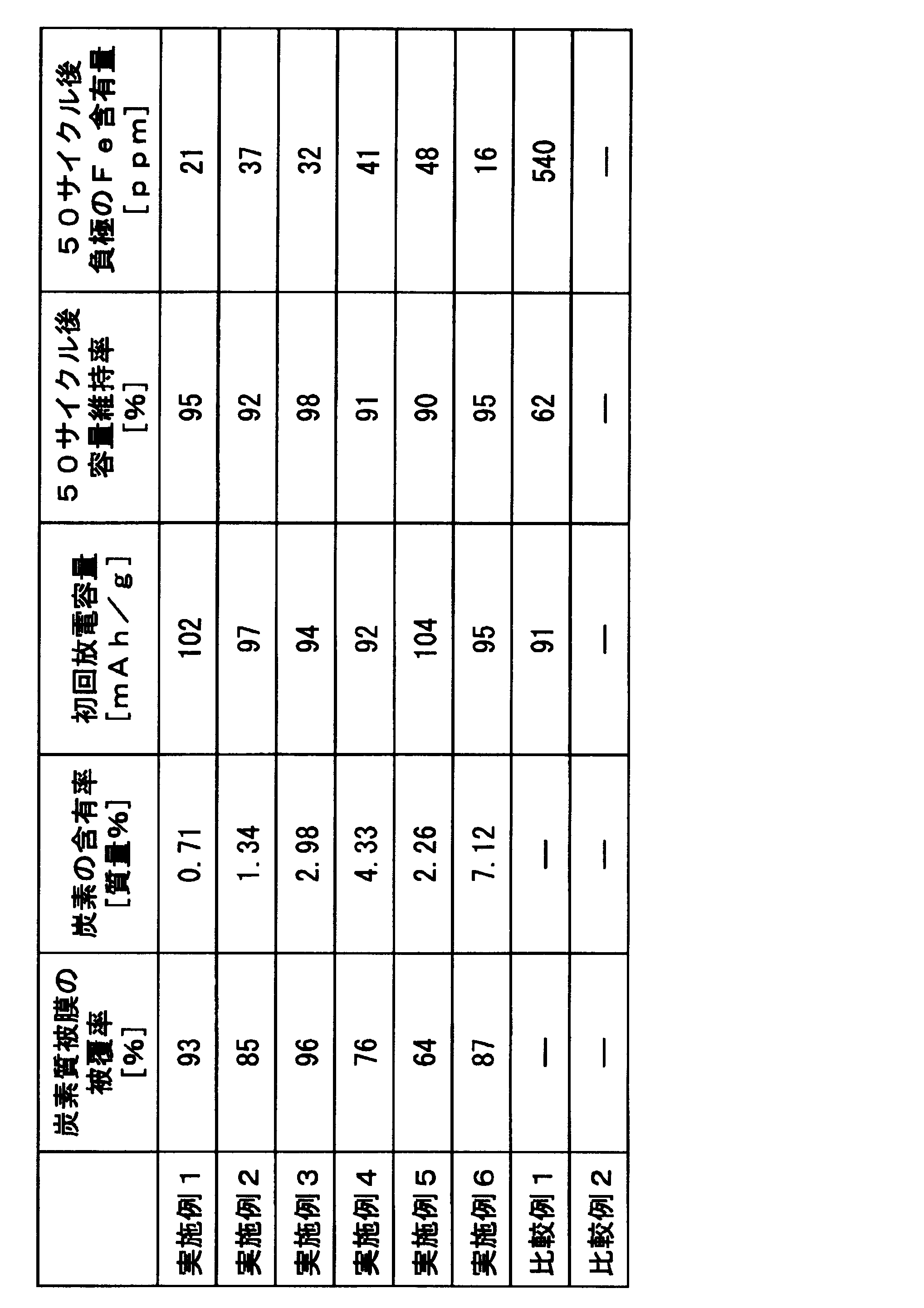
表2の結果から、実施例1~6の正極材料は、450℃で熱処理することにより、Na2Fe2(SO4)3粒子が炭素質被膜で被覆されているので、電解液へ遷移金属イオンが溶出するのが抑制され、優れた充放電サイクル特性を示していることが分かった。
一方、比較例1の正極材料は、Na2Fe2(SO4)3粒子が炭素質被膜で被覆されていないので、電解液へ遷移金属イオンが溶出するのを抑制することができず、充放電サイクル特性が大きく低下していることが分かった。
本発明の正極材料は、500℃以下の低温プロセスによって、Na2Fe2(SO4)3粒子が炭素質被膜で被覆されているので、炭素質被膜の被覆率が高く、耐水性に優れ、電子伝導性が高いため、Na2Fe2(SO4)3粒子の有する、高容量かつ高エネルギー効果を充分に発揮することができるから、より高電圧、高エネルギー密度、高負荷特性及び高速充放電特性が期待される次世代の二次電池に対しても適用することが可能であり、次世代の二次電池の場合、その効果は非常に大きなものである。
Claims (6)
- 構造内の2つのMO6が稜共有して二量体を形成したM2O10二量体結晶構造を有するNaxMy(SO4)y(但し、MはSc、Ti、V、Cr、Mn、Fe、Co、Ni、Cu、Zn、Y、Zr、Nb、Mo、Tc、Ru、Rh、Pd、Agの群から選択される1種または2種以上、1.6≦x≦2.4、1.6≦y≦2.4、2.4≦z≦3.6)で表されるナトリウム硫酸塩化合物を含有してなる正極活物質粒子と、該正極活物質粒子の表面を被覆する炭素質被膜とからなる炭素質電極活物質複合粒子を含むことを特徴とする正極材料。
- 前記炭素質被膜が、500℃以下の低温プロセスによって形成されたことを特徴とする請求項1に記載の正極材料。
- 前記正極活物質粒子の表面における前記炭素質被膜の被覆率は、60%以上であることを特徴とする請求項1または2に記載の正極材料。
- 前記炭素質電極活物質複合粒子は、前記炭素質被膜で被覆された前記正極活物質粒子の一次粒子を複数個凝集した凝集粒子からなり、かつ、前記一次粒子間に前記炭素質被膜を介在させてなることを特徴とする請求項1から3のいずれか1項に記載の正極材料。
- 請求項1から4のいずれか1項に記載の正極材料と、導電助剤と、結着剤と、を含有してなることを特徴とするペースト。
- 請求項5に記載のペーストを用いて集電体の一主面に正極が形成されてなる電極板を備えてなることを特徴とするナトリウムイオン電池。
Applications Claiming Priority (2)
| Application Number | Priority Date | Filing Date | Title |
|---|---|---|---|
| JP2014-091866 | 2014-04-25 | ||
| JP2014091866A JP6741390B2 (ja) | 2014-04-25 | 2014-04-25 | 正極材料、ペースト及びナトリウムイオン電池 |
Publications (1)
| Publication Number | Publication Date |
|---|---|
| WO2015163045A1 true WO2015163045A1 (ja) | 2015-10-29 |
Family
ID=54332216
Family Applications (1)
| Application Number | Title | Priority Date | Filing Date |
|---|---|---|---|
| PCT/JP2015/057990 Ceased WO2015163045A1 (ja) | 2014-04-25 | 2015-03-18 | 正極材料、ペースト及びナトリウムイオン電池 |
Country Status (2)
| Country | Link |
|---|---|
| JP (1) | JP6741390B2 (ja) |
| WO (1) | WO2015163045A1 (ja) |
Cited By (3)
| Publication number | Priority date | Publication date | Assignee | Title |
|---|---|---|---|---|
| WO2017119171A1 (ja) * | 2016-01-06 | 2017-07-13 | ソニー株式会社 | 非水系二次電池、並びに、非水系二次電池用の正極活物質及びその製造方法 |
| CN108134047A (zh) * | 2016-12-01 | 2018-06-08 | 中国科学院大连化学物理研究所 | 高担量活性物质电极制备及其电极和应用 |
| CN108786875A (zh) * | 2018-04-11 | 2018-11-13 | 天津大学 | 一种Zn-Zr双金属二聚体催化剂的制备方法 |
Families Citing this family (6)
| Publication number | Priority date | Publication date | Assignee | Title |
|---|---|---|---|---|
| KR101953757B1 (ko) * | 2016-02-05 | 2019-03-04 | 주식회사 엘지화학 | 음극활물질 및 이를 포함하는 이차전지 |
| KR102568677B1 (ko) * | 2021-02-01 | 2023-08-18 | 세종대학교산학협력단 | 포타슘이온 이차전지용 양극 활물질, 이의 제조방법 및 이를 포함하는 포타슘이온 이차전지 |
| KR20240029037A (ko) * | 2021-07-07 | 2024-03-05 | 스페셜티 오퍼레이션스 프랑스 | 나트륨 이온 배터리에서 전이 금속 이온을 포획하기 위한 무기 첨가제 |
| JP7246789B1 (ja) | 2021-12-28 | 2023-03-28 | 株式会社ルネシス | 正極活物質、正極合剤及び二次電池 |
| KR20240083584A (ko) | 2022-12-05 | 2024-06-12 | 에스케이이노베이션 주식회사 | 리튬 이차 전지용 양극 활물질 및 이를 포함하는 리튬 이차 전지 |
| CN116417617B (zh) * | 2023-05-26 | 2023-10-24 | 宁德新能源科技有限公司 | 正极材料、正极极片、钠离子二次电池和用电装置 |
Citations (4)
| Publication number | Priority date | Publication date | Assignee | Title |
|---|---|---|---|---|
| WO2005036690A1 (ja) * | 2003-10-07 | 2005-04-21 | Gs Yuasa Corporation | 非水電解質二次電池 |
| JP2011076931A (ja) * | 2009-09-30 | 2011-04-14 | Nagoya Univ | リチウムイオン二次電池の正極材、およびその製造方法 |
| WO2013114102A1 (en) * | 2012-02-01 | 2013-08-08 | Faradion Ltd | Sulfate electrodes |
| WO2015037489A1 (ja) * | 2013-09-11 | 2015-03-19 | 国立大学法人 東京大学 | ナトリウムイオン二次電池用正極材料 |
Family Cites Families (7)
| Publication number | Priority date | Publication date | Assignee | Title |
|---|---|---|---|---|
| JP2847663B2 (ja) * | 1992-10-06 | 1999-01-20 | 日本電信電話株式会社 | 非水電解質電池 |
| JP5851707B2 (ja) * | 2011-04-01 | 2016-02-03 | 三井造船株式会社 | リン酸鉄リチウム正極材料およびその製造方法 |
| JP5981101B2 (ja) * | 2011-06-15 | 2016-08-31 | 株式会社東芝 | 非水電解質二次電池 |
| KR101316066B1 (ko) * | 2011-09-27 | 2013-10-11 | 전자부품연구원 | 이차전지용 양극재료 및 이의 제조방법 |
| JP2013095613A (ja) * | 2011-10-28 | 2013-05-20 | Toyota Motor Corp | 炭素被覆LiVP2O7粒子とその製造方法、及びリチウムイオン二次電池 |
| JP5478693B2 (ja) * | 2012-03-23 | 2014-04-23 | 太平洋セメント株式会社 | 二次電池用正極活物質及びその製造方法 |
| JP2015115283A (ja) * | 2013-12-13 | 2015-06-22 | 日本電信電話株式会社 | ナトリウム二次電池及び該ナトリウム二次電池に使用する正極材料の製造方法 |
-
2014
- 2014-04-25 JP JP2014091866A patent/JP6741390B2/ja active Active
-
2015
- 2015-03-18 WO PCT/JP2015/057990 patent/WO2015163045A1/ja not_active Ceased
Patent Citations (4)
| Publication number | Priority date | Publication date | Assignee | Title |
|---|---|---|---|---|
| WO2005036690A1 (ja) * | 2003-10-07 | 2005-04-21 | Gs Yuasa Corporation | 非水電解質二次電池 |
| JP2011076931A (ja) * | 2009-09-30 | 2011-04-14 | Nagoya Univ | リチウムイオン二次電池の正極材、およびその製造方法 |
| WO2013114102A1 (en) * | 2012-02-01 | 2013-08-08 | Faradion Ltd | Sulfate electrodes |
| WO2015037489A1 (ja) * | 2013-09-11 | 2015-03-19 | 国立大学法人 東京大学 | ナトリウムイオン二次電池用正極材料 |
Cited By (10)
| Publication number | Priority date | Publication date | Assignee | Title |
|---|---|---|---|---|
| WO2017119171A1 (ja) * | 2016-01-06 | 2017-07-13 | ソニー株式会社 | 非水系二次電池、並びに、非水系二次電池用の正極活物質及びその製造方法 |
| JPWO2017119171A1 (ja) * | 2016-01-06 | 2018-07-19 | 株式会社村田製作所 | 非水系二次電池、並びに、非水系二次電池用の正極活物質及びその製造方法 |
| CN108475813A (zh) * | 2016-01-06 | 2018-08-31 | 株式会社村田制作所 | 非水二次电池、用于非水二次电池的正极活性物质及其制造方法 |
| US20180316055A1 (en) * | 2016-01-06 | 2018-11-01 | Murata Manufacturing Co., Ltd. | Nonaqueous secondary battery, and positive electrode active material for nonaqueous secondary battery and production method therefor |
| EP3373376A4 (en) * | 2016-01-06 | 2019-07-17 | Murata Manufacturing Co., Ltd. | SECONDARY BATTERIES WITH A WATER-FREE ELECTROLYTE, POSITIVE ELECTRODE ACTIVE MATERIAL FOR SECONDARY BATTERIES WITH A WATER-FREE ELECTROLYTE AND METHOD FOR THE PRODUCTION THEREOF |
| CN108475813B (zh) * | 2016-01-06 | 2021-07-02 | 株式会社村田制作所 | 非水二次电池、用于非水二次电池的正极活性物质及其制造方法 |
| EP3373376B1 (en) * | 2016-01-06 | 2025-05-21 | Murata Manufacturing Co., Ltd. | Nonaqueous secondary battery, and positive electrode active material for nonaqueous secondary batteries and method for producing same |
| CN108134047A (zh) * | 2016-12-01 | 2018-06-08 | 中国科学院大连化学物理研究所 | 高担量活性物质电极制备及其电极和应用 |
| CN108786875A (zh) * | 2018-04-11 | 2018-11-13 | 天津大学 | 一种Zn-Zr双金属二聚体催化剂的制备方法 |
| CN108786875B (zh) * | 2018-04-11 | 2021-04-20 | 天津大学 | 一种Zn-Zr双金属二聚体催化剂的制备方法 |
Also Published As
| Publication number | Publication date |
|---|---|
| JP6741390B2 (ja) | 2020-08-19 |
| JP2015210956A (ja) | 2015-11-24 |
Similar Documents
| Publication | Publication Date | Title |
|---|---|---|
| JP6741390B2 (ja) | 正極材料、ペースト及びナトリウムイオン電池 | |
| JP2010212309A (ja) | 電極材料及びこの電極材料を含有する電極 | |
| JP6801758B1 (ja) | リチウムイオン二次電池用正極材料、リチウムイオン二次電池用正極、及びリチウムイオン二次電池 | |
| JP6424934B1 (ja) | リチウムイオン二次電池用正極材料、リチウムイオン二次電池用正極、リチウムイオン二次電池 | |
| JP6210144B1 (ja) | リチウムイオン二次電池用正極材料、リチウムイオン二次電池用正極、リチウムイオン二次電池 | |
| JP6288338B1 (ja) | リチウムイオン二次電池用正極材料、リチウムイオン二次電池用正極、リチウムイオン二次電池 | |
| JP5822017B1 (ja) | 電極材料、電極用ペースト及びリチウムイオン電池 | |
| US11374221B2 (en) | Lithium-ion secondary battery | |
| JP6332539B1 (ja) | リチウムイオン二次電池用正極材料、リチウムイオン二次電池用正極、リチウムイオン二次電池 | |
| JP6319498B1 (ja) | リチウムイオン二次電池用正極材料、リチウムイオン二次電池用正極、リチウムイオン二次電池 | |
| CN101593826A (zh) | 锂离子电池SnSb合金/石墨纳米片复合材料负极及其制备方法 | |
| JP6097198B2 (ja) | 電極材料及び電極並びにリチウムイオン電池 | |
| JP5790745B2 (ja) | リチウムイオン二次電池用電極材料およびその製造方法 | |
| JP5861650B2 (ja) | 電極材料及び電極並びにリチウムイオン電池 | |
| JP6264407B2 (ja) | リチウムイオン二次電池 | |
| JP6332540B1 (ja) | リチウムイオン二次電池用正極材料、リチウムイオン二次電池用正極、リチウムイオン二次電池 | |
| JP6930641B1 (ja) | リチウムイオン二次電池用金属吸着材担持炭素材料、リチウムイオン二次電池用正極材料、リチウムイオン二次電池用正極、リチウムイオン二次電池 | |
| JP6766936B1 (ja) | リチウムイオン二次電池用正極材料、リチウムイオン二次電池用正極、及びリチウムイオン二次電池 | |
| JP2014146514A (ja) | 電極材料及び電極並びにリチウムイオン電池 | |
| JP6090497B1 (ja) | リチウムイオン二次電池用正極材料 | |
| JP5843038B2 (ja) | リチウムイオン二次電池用電極材料 | |
| EP4589686A1 (en) | Cathode active material, cathode for lithium secondary battery, and lithium secondary battery | |
| JP6065133B1 (ja) | リチウムイオン二次電池用正極材料、リチウムイオン二次電池用正極、リチウムイオン二次電池 |
Legal Events
| Date | Code | Title | Description |
|---|---|---|---|
| 121 | Ep: the epo has been informed by wipo that ep was designated in this application |
Ref document number: 15783254 Country of ref document: EP Kind code of ref document: A1 |
|
| NENP | Non-entry into the national phase |
Ref country code: DE |
|
| 122 | Ep: pct application non-entry in european phase |
Ref document number: 15783254 Country of ref document: EP Kind code of ref document: A1 |