WO2015163015A1 - 作業機械の周囲監視装置 - Google Patents
作業機械の周囲監視装置 Download PDFInfo
- Publication number
- WO2015163015A1 WO2015163015A1 PCT/JP2015/056432 JP2015056432W WO2015163015A1 WO 2015163015 A1 WO2015163015 A1 WO 2015163015A1 JP 2015056432 W JP2015056432 W JP 2015056432W WO 2015163015 A1 WO2015163015 A1 WO 2015163015A1
- Authority
- WO
- WIPO (PCT)
- Prior art keywords
- shadow
- image
- feature pattern
- work machine
- contour
- Prior art date
- Legal status (The legal status is an assumption and is not a legal conclusion. Google has not performed a legal analysis and makes no representation as to the accuracy of the status listed.)
- Ceased
Links
Images


Classifications
-
- H—ELECTRICITY
- H04—ELECTRIC COMMUNICATION TECHNIQUE
- H04N—PICTORIAL COMMUNICATION, e.g. TELEVISION
- H04N7/00—Television systems
- H04N7/18—Closed-circuit television [CCTV] systems, i.e. systems in which the video signal is not broadcast
- H04N7/181—Closed-circuit television [CCTV] systems, i.e. systems in which the video signal is not broadcast for receiving images from a plurality of remote sources
-
- B—PERFORMING OPERATIONS; TRANSPORTING
- B60—VEHICLES IN GENERAL
- B60R—VEHICLES, VEHICLE FITTINGS, OR VEHICLE PARTS, NOT OTHERWISE PROVIDED FOR
- B60R1/00—Optical viewing arrangements; Real-time viewing arrangements for drivers or passengers using optical image capturing systems, e.g. cameras or video systems specially adapted for use in or on vehicles
- B60R1/002—Optical viewing arrangements; Real-time viewing arrangements for drivers or passengers using optical image capturing systems, e.g. cameras or video systems specially adapted for use in or on vehicles specially adapted for covering the peripheral part of the vehicle, e.g. for viewing tyres, bumpers or the like
-
- B—PERFORMING OPERATIONS; TRANSPORTING
- B60—VEHICLES IN GENERAL
- B60R—VEHICLES, VEHICLE FITTINGS, OR VEHICLE PARTS, NOT OTHERWISE PROVIDED FOR
- B60R1/00—Optical viewing arrangements; Real-time viewing arrangements for drivers or passengers using optical image capturing systems, e.g. cameras or video systems specially adapted for use in or on vehicles
- B60R1/20—Real-time viewing arrangements for drivers or passengers using optical image capturing systems, e.g. cameras or video systems specially adapted for use in or on vehicles
- B60R1/22—Real-time viewing arrangements for drivers or passengers using optical image capturing systems, e.g. cameras or video systems specially adapted for use in or on vehicles for viewing an area outside the vehicle, e.g. the exterior of the vehicle
- B60R1/23—Real-time viewing arrangements for drivers or passengers using optical image capturing systems, e.g. cameras or video systems specially adapted for use in or on vehicles for viewing an area outside the vehicle, e.g. the exterior of the vehicle with a predetermined field of view
- B60R1/27—Real-time viewing arrangements for drivers or passengers using optical image capturing systems, e.g. cameras or video systems specially adapted for use in or on vehicles for viewing an area outside the vehicle, e.g. the exterior of the vehicle with a predetermined field of view providing all-round vision, e.g. using omnidirectional cameras
-
- B—PERFORMING OPERATIONS; TRANSPORTING
- B60—VEHICLES IN GENERAL
- B60R—VEHICLES, VEHICLE FITTINGS, OR VEHICLE PARTS, NOT OTHERWISE PROVIDED FOR
- B60R11/00—Arrangements for holding or mounting articles, not otherwise provided for
- B60R11/04—Mounting of cameras operative during drive; Arrangement of controls thereof relative to the vehicle
-
- E—FIXED CONSTRUCTIONS
- E02—HYDRAULIC ENGINEERING; FOUNDATIONS; SOIL SHIFTING
- E02F—DREDGING; SOIL-SHIFTING
- E02F9/00—Component parts of dredgers or soil-shifting machines, not restricted to one of the kinds covered by groups E02F3/00 - E02F7/00
- E02F9/24—Safety devices, e.g. for preventing overload
-
- E—FIXED CONSTRUCTIONS
- E02—HYDRAULIC ENGINEERING; FOUNDATIONS; SOIL SHIFTING
- E02F—DREDGING; SOIL-SHIFTING
- E02F9/00—Component parts of dredgers or soil-shifting machines, not restricted to one of the kinds covered by groups E02F3/00 - E02F7/00
- E02F9/26—Indicating devices
- E02F9/261—Surveying the work-site to be treated
-
- G—PHYSICS
- G06—COMPUTING OR CALCULATING; COUNTING
- G06T—IMAGE DATA PROCESSING OR GENERATION, IN GENERAL
- G06T7/00—Image analysis
- G06T7/10—Segmentation; Edge detection
- G06T7/11—Region-based segmentation
-
- G—PHYSICS
- G06—COMPUTING OR CALCULATING; COUNTING
- G06T—IMAGE DATA PROCESSING OR GENERATION, IN GENERAL
- G06T7/00—Image analysis
- G06T7/10—Segmentation; Edge detection
- G06T7/194—Segmentation; Edge detection involving foreground-background segmentation
-
- G—PHYSICS
- G06—COMPUTING OR CALCULATING; COUNTING
- G06V—IMAGE OR VIDEO RECOGNITION OR UNDERSTANDING
- G06V10/00—Arrangements for image or video recognition or understanding
- G06V10/40—Extraction of image or video features
- G06V10/44—Local feature extraction by analysis of parts of the pattern, e.g. by detecting edges, contours, loops, corners, strokes or intersections; Connectivity analysis, e.g. of connected components
-
- G—PHYSICS
- G06—COMPUTING OR CALCULATING; COUNTING
- G06V—IMAGE OR VIDEO RECOGNITION OR UNDERSTANDING
- G06V20/00—Scenes; Scene-specific elements
- G06V20/50—Context or environment of the image
- G06V20/56—Context or environment of the image exterior to a vehicle by using sensors mounted on the vehicle
- G06V20/58—Recognition of moving objects or obstacles, e.g. vehicles or pedestrians; Recognition of traffic objects, e.g. traffic signs, traffic lights or roads
-
- G—PHYSICS
- G08—SIGNALLING
- G08G—TRAFFIC CONTROL SYSTEMS
- G08G1/00—Traffic control systems for road vehicles
- G08G1/16—Anti-collision systems
- G08G1/165—Anti-collision systems for passive traffic, e.g. including static obstacles, trees
-
- G—PHYSICS
- G08—SIGNALLING
- G08G—TRAFFIC CONTROL SYSTEMS
- G08G1/00—Traffic control systems for road vehicles
- G08G1/16—Anti-collision systems
- G08G1/166—Anti-collision systems for active traffic, e.g. moving vehicles, pedestrians, bikes
-
- B—PERFORMING OPERATIONS; TRANSPORTING
- B60—VEHICLES IN GENERAL
- B60R—VEHICLES, VEHICLE FITTINGS, OR VEHICLE PARTS, NOT OTHERWISE PROVIDED FOR
- B60R2300/00—Details of viewing arrangements using cameras and displays, specially adapted for use in a vehicle
- B60R2300/30—Details of viewing arrangements using cameras and displays, specially adapted for use in a vehicle characterised by the type of image processing
-
- B—PERFORMING OPERATIONS; TRANSPORTING
- B60—VEHICLES IN GENERAL
- B60R—VEHICLES, VEHICLE FITTINGS, OR VEHICLE PARTS, NOT OTHERWISE PROVIDED FOR
- B60R2300/00—Details of viewing arrangements using cameras and displays, specially adapted for use in a vehicle
- B60R2300/60—Details of viewing arrangements using cameras and displays, specially adapted for use in a vehicle characterised by monitoring and displaying vehicle exterior scenes from a transformed perspective
- B60R2300/607—Details of viewing arrangements using cameras and displays, specially adapted for use in a vehicle characterised by monitoring and displaying vehicle exterior scenes from a transformed perspective from a bird's eye viewpoint
-
- B—PERFORMING OPERATIONS; TRANSPORTING
- B60—VEHICLES IN GENERAL
- B60R—VEHICLES, VEHICLE FITTINGS, OR VEHICLE PARTS, NOT OTHERWISE PROVIDED FOR
- B60R2300/00—Details of viewing arrangements using cameras and displays, specially adapted for use in a vehicle
- B60R2300/80—Details of viewing arrangements using cameras and displays, specially adapted for use in a vehicle characterised by the intended use of the viewing arrangement
- B60R2300/802—Details of viewing arrangements using cameras and displays, specially adapted for use in a vehicle characterised by the intended use of the viewing arrangement for monitoring and displaying vehicle exterior blind spot views
-
- B—PERFORMING OPERATIONS; TRANSPORTING
- B60—VEHICLES IN GENERAL
- B60R—VEHICLES, VEHICLE FITTINGS, OR VEHICLE PARTS, NOT OTHERWISE PROVIDED FOR
- B60R2300/00—Details of viewing arrangements using cameras and displays, specially adapted for use in a vehicle
- B60R2300/80—Details of viewing arrangements using cameras and displays, specially adapted for use in a vehicle characterised by the intended use of the viewing arrangement
- B60R2300/8093—Details of viewing arrangements using cameras and displays, specially adapted for use in a vehicle characterised by the intended use of the viewing arrangement for obstacle warning
-
- G—PHYSICS
- G06—COMPUTING OR CALCULATING; COUNTING
- G06T—IMAGE DATA PROCESSING OR GENERATION, IN GENERAL
- G06T2207/00—Indexing scheme for image analysis or image enhancement
- G06T2207/30—Subject of image; Context of image processing
- G06T2207/30248—Vehicle exterior or interior
- G06T2207/30252—Vehicle exterior; Vicinity of vehicle
- G06T2207/30261—Obstacle
Definitions
- the present invention relates to a surrounding monitoring device for a working machine that monitors obstacles around the working machine using a monocular camera image.
- Patent Document 1 JP 2007-272292 (Patent Document 1) as a background art in this technical field.
- a pattern indicating a relationship between pixel values of edge pixels belonging to an edge of an object to be imaged in an image captured by an imaging device and a plurality of pixels existing in the vicinity of the edge pixel is calculated, Refer to the shadow boundary pattern in which the relationship between the pixel values of the shadow boundary pixels that belong to the shadow boundary between the shadow area and the non-shadow area in the image and the pixels that exist in the vicinity of the shadow boundary pixel is preset.
- a shadow boundary extraction method is described in which the shadow boundary pattern is compared with the calculated pattern, and the edge pixel belonging to the calculated pattern that matches the shadow boundary pattern is determined as a pixel existing in the shadow boundary.
- the contour shape of a work machine including a dump truck and a hydraulic excavator to which the present invention is applied is more complex than that of a passenger car, so the shadow of the work machine projected on the ground (hereinafter referred to as the own vehicle shadow). Is naturally complicated. Furthermore, since it is assumed that the work machine travels off-road, the own vehicle shadow has a more complicated shape than that of a passenger car in which the own vehicle shadow is often projected on a paved road. In addition, it can be pointed out that when the work machine runs off-road, the shape of the vehicle shadow changes dynamically according to the unevenness of the ground surface, so the shape of the vehicle shadow changes with time.
- shadow boundary patterns when a method of preparing in advance a plurality of shadow boundary patterns (shadow boundary patterns) appearing on the ground as in the technique of the above-mentioned document, an infinite number of shadow boundary patterns are formed in accordance with the contour of the work machine and the road surface shape. It is prepared and stored in a storage device such as a memory. However, it is practically impossible to create a shadow boundary pattern in accordance with any road surface shape, and even if it can be created, it is necessary to prepare a storage device such as a memory that can store a huge amount of data. Therefore, it is not realistic from the viewpoint of initial cost. Furthermore, since it is predicted that enormous processing is required for collation of countless shadow boundary patterns and calculated patterns, it is not realistic from the viewpoint of processing contents.
- the vehicle's shadow cannot be accurately recognized, for example, the vehicle's shadow may be misrecognized as an object (obstacle) around the work machine, and a warning that is not necessary may be issued, resulting in a decrease in work efficiency. There is.
- the object of the present invention is that even if a shadow of a vehicle having a complicated shape exists in an image obtained by photographing the periphery of the work machine, the presence of the shadow of the vehicle affects the detection of objects existing around the work machine.
- An object of the present invention is to provide a work machine surrounding monitoring device capable of preventing the above-mentioned problem.
- the present invention provides a monocular camera that is mounted on a work machine and captures an image around the work machine, and a feature pattern that extracts a feature pattern in the image based on a feature amount of the image. From the feature pattern extracted by the extraction unit, the shadow contour extraction unit that extracts the contour of the region that can be regarded as the shadow of the work machine in the image based on the feature amount of the image, and the feature pattern extracted by the feature pattern extraction unit, And an object detection unit that detects an obstacle existing around the work machine based on the remaining feature patterns excluding the feature pattern located on the contour extracted by the shadow contour extraction unit.
- the present invention even if a vehicle shadow having a complex shape that changes with time in an image obtained by photographing the periphery of the work machine exists, a portion regarded as the contour of the vehicle shadow is appropriately detected from the obstacle detection target. Therefore, it is possible to prevent misrecognition of the vehicle shadow and improve the obstacle detection accuracy.
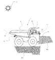
- FIG. 1 Top view of dump truck according to the present embodiment
- the side view of the dump truck 1 shown in FIG. 1 is an overall configuration diagram of an image processing apparatus.
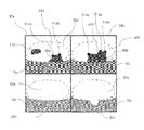
- combination part An example of the image which combined the input image of four cameras in the image composition part.
- a process target area setting procedure that is performed in advance before the area is specified by the reference process target area setting unit.
- FIG. The flowchart of the process performed by the shadow presence determination part 42 and the shadow area extraction part 43.
- FIG. 9 is a luminance distribution diagram of step 42b in FIG.
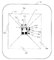
- FIG. 18 is a diagram showing an example of an image in which the shadow outline feature pattern mask portion is expanded a predetermined number of times in step 60b at the corner point 51e, corner points 51A, 51B, 51C, 51D, 51E, 51F, 51G, 51H, and 51P in FIG.
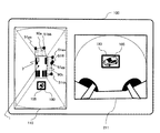
- region masked by the shadow outline feature pattern mask part on the display apparatus with the bird's-eye view image The figure which shows an example of the screen which displayed the area
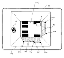
- the figure which shows an example of the display screen of a display apparatus The figure which shows an example of the display screen of a display apparatus.
- the figure which shows an example of the display screen of a display apparatus. The figure which shows an example of the display screen of a display apparatus.
- the working machine surrounding monitoring apparatus which will be described later, is based on a monocular camera (for example, a camera 6 described later) that is mounted on the working machine and captures an image of the surrounding of the working machine, and a feature amount of the image.
- a feature pattern extraction unit (for example, a feature pattern extraction unit 170 described later) that extracts a feature pattern in the image (for example, a corner or an edge in the image) and a shadow of the work machine in the image.
- a shadow contour extracting unit (for example, shadow contour extracting unit 40 described later) that extracts the contour of the region based on the feature amount of the image, and the shadow contour extracting unit from the feature pattern extracted by the feature pattern extracting unit Based on the remaining feature pattern excluding the feature pattern located on the contour extracted in step (b), an object detection unit (for example, described later) that detects an obstacle existing around the work machine. Characterized in that it comprises an object detection section 180) and.
- the outline of the shadow is extracted at every sampling interval regardless of the complexity of the shape of the shadow (vehicle shadow) of the work machine, and is displayed on the shadow outline. Since the located feature pattern is excluded from the obstacle detection targets, it is possible to prevent the vehicle shadow from being erroneously recognized as an obstacle. Furthermore, since the feature pattern that does not exist on the shadow contour is still an obstacle detection target by the object detection unit, for example, an obstacle such as an automobile exists on the shadow contour, and the feature pattern related to the obstacle Even if those existing on the shadow outline are removed, the remaining feature patterns (for example, feature patterns existing inside the vehicle shadow) still remain as obstacle detection targets. If the obstacle detection is performed based on this, the obstacle can be detected immediately.
- the black obstacle for example, a black passenger car
- the contour may be regarded as a shadow contour.
- the feature pattern related to the obstacle remains outside and inside the subject vehicle shadow. Therefore, the obstacle is detected based on the remaining feature pattern. Is possible. That is, with the configuration of the surrounding monitoring device described above, it is not necessary to accurately recognize the shadow boundary of the work machine, and an obstacle can be detected quickly even when the shadow boundary is erroneously recognized.
- a portion regarded as the contour of the vehicle shadow is an obstacle. Since it is appropriately excluded from the detection targets, it is possible to prevent erroneous recognition of the vehicle shadow and improve the obstacle detection accuracy.
- a color derived from a mineral for example, a reddish brown color unique to iron ore at an iron ore mining site
- a color in the image is selected as the feature amount when extracting the own vehicle shadow from the captured image of the monocular camera, there is an increased risk that the extraction performance of the own vehicle shadow and the shadow outline will deteriorate.
- the color since the color also changes due to a change in light, it is not appropriate to select a color as a feature amount from this viewpoint.
- the work machine since the color of the image is not used as a feature amount when extracting the shadow of the own vehicle, the work machine can be used even in places where irregular color changes appear on the ground, such as a mine. It will not interfere with the detection of obstacles around.
- Another advantage of the present invention is that an object existing around the work machine can be detected from a single image (still image) captured by a monocular camera.
- the “feature pattern” in the above indicates the shape of the feature detected by extracting the feature of the image based on the feature amount. For example, a point (corner), a line / contour line (edge), a region And so on.
- the work machine is not limited to a dump truck. That is, the present invention can be applied to any work machine that performs a predetermined work (transportation, excavation, etc.) including a hydraulic excavator.
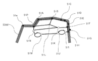
- FIG. 1 shows a top view of the dump truck according to the present embodiment.
- the dump truck 1 shown in this figure includes a body frame 2, a front wheel 3 (3L and 3R) and a rear wheel 4 (4L and 4R) that are rotatably attached to the body frame 2, and an upper part of the body frame 2.
- a monolithic camera 6 (6a and 6b and 6c and 6d) fixed to the chassis, the vehicle body frame 2 and the like, a driver's cab 7 provided at the upper front of the vehicle body frame 2,
- An image processing device 10 mounted at an arbitrary location on the vehicle body frame 2 (for example, inside the cab 7) and a display device 100 provided inside the cab 7 are provided.
- the body frame 2 forms the main body of the dump truck 1, and a front wheel 3 is provided in front of the body frame 2 and a rear wheel 4 is provided in the rear.
- the front wheel 3R is a front wheel on the right side of the vehicle, and the front wheel 3L is a front wheel on the left side of the vehicle.
- the rear wheel 4R is two rear wheels on the right side of the vehicle, and the rear wheel 4L is two rear wheels on the left side of the vehicle.
- the vessel 5 is a so-called cargo bed and is used for loading earth and sand, minerals, and the like.
- positioning and the number of the front wheel 3 and the rear wheel 4 which were illustrated are only an example.
- the monocular camera 6 which is an imaging device can be installed at an arbitrary position of the dump truck 1.
- a total of four cameras 6a, 6b, 6c, 6d are mounted, and the camera 6a includes the vehicle front 15a in the field of view range 11 (the range of the broken line 11 in FIG. 1).
- the dump truck 1 is installed at the upper front of the dump truck 1 so as to look down obliquely downward.
- the camera 6b is installed on the upper right side of the vehicle so that the visual field range 12 includes the vehicle right side 15b
- the camera 6c is disposed on the rear side of the vehicle so that the visual field range 13 includes the vehicle rear 15c.
- the camera 6d is installed on the upper left side of the vehicle so that the visual field range 14 includes the left side 15d of the vehicle.
- the shadow of the dump truck 1 (own vehicle shadow) is generated in the front 90a and the right side 90b.
- the shadows 90a and 90b appearing on the front and right sides of the dump truck 1 are schematically divided and displayed, but in reality, the two shadows 90a and 90b are connected (later figure). The same shall apply).
- FIG. 2 shows a side view of the dump truck 1 shown in FIG.
- a camera 6a having a front visual field range 11 (a range indicated by a broken line 11 in FIG. 2) is attached to a position diagonally forward right when viewed from the cab 7, and has a right side visual field range 12 (a range indicated by a broken line 12 in FIG. 2).
- 6b is attached to a position obliquely rearward to the right when viewed from the cab 7, and a camera 6c having a rear visual field range 13 (a range indicated by a broken line 13 in FIG. 2) is attached to the rear of the vehicle body frame 2.
- the right-side view range 12 (not shown in FIG. 2) camera 6d is attached to a position diagonally left rearward when viewed from the cab 7, but is not shown in FIG. Images captured by the camera 6a, the camera 6b, the camera 6c, and the camera 6d are output to the image processing apparatus 10 as image data.
- the cab 7 is provided with various operation means including a steering handle, an accelerator pedal, and a brake pedal for an operator to board and operate the dump truck 1. As another operation means, for example, there is a shift lever for moving the dump truck 1 forward or backward.
- the cab 7 is provided with an image processing device 10 and a display device 100. Image data photographed and generated by the camera 6a, the camera 6b, the camera 6c, and the camera 6d is subjected to predetermined image processing by the image processing device 10. Done. The image data that has undergone image processing is displayed on the display device 100. Basically, the display device 100 displays images taken by the camera 6a, the camera 6b, the camera 6c, and the camera 6d.
- the front visual field range 11 is an obliquely lower area in front of the dump truck 1.
- the front visual field range 11 may include workers, other work machines, service cars, and the like.
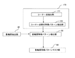
- FIG. 3 is an overall configuration diagram of the image processing apparatus 10 according to the first embodiment of the present invention.
- the image processing apparatus 10 shown in this figure includes an image input unit 20, an image storage unit 30, an image synthesis unit 35, a reference processing target area setting unit 80, a feature pattern extraction unit 170, and a shadow outline extraction unit 40.
- the camera images taken by the four cameras 6a, 6b, 6c, and 6d are input to the image input unit 20 at predetermined sampling intervals and stored in the image storage unit 30.
- the image storage unit 30 samples and stores input images from the image input unit 20 at different intervals. For example, the image storage unit 30 stores a longer sampling interval when stopped and a shorter sampling interval when moving, so that the minimum necessary amount is stored.
- the input image can be used for image processing, and the time can be shortened and the processing can be optimized.
- the image composition unit 35 synthesizes a plurality of camera images output from the four cameras 6a, 6b, 6c, and 6d and stored in the image storage unit 30 into one image.
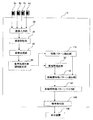
- FIG. 4 shows an example of a processing procedure executed by the image composition unit 35 of the work machine surrounding monitoring apparatus of the present invention.
- the image composition unit 35 determines which of the four cameras 6a, 6b, 6c, 6d is an image of the camera. Then, in the case of the front camera 6a, the processing is performed at the upper left of the image processing screen (step 35b), and in the case of the right camera 6b, the processing is performed at the upper right of the image processing screen (step 35c). In the case of the camera 6c, processing is performed at the lower right of the image processing screen (step 35d), and in the case of the left camera 6d, processing is performed at the lower left of the image processing screen (step 35e).
- a composite image is generated with the images of the four cameras 6a, 6b, 6c, and 6d as one frame (step 35f).
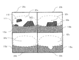
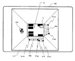
- the image composition unit 35 combines the input image 20a of the camera 6a, the input image 20b of the camera 6b, the input image 20c of the camera 6c, and the input image 20d of the camera 6d of the surroundings monitoring device of the work machine of the present invention.
- An example is shown in FIG. In FIG. 5, the own vehicle shadow 90a occurs in the input image 20a, and the own vehicle shadow 90b occurs in the input image 20b.
- the input image 20a there are a black car 110 and a non-own car shadow 111 as dark areas similar to the own car shadow 90a (for example, when a black car is lurking below the work machine). The black car is not the shadow of the work machine (own car shadow).
- the area of the dark region is a predetermined value (the predetermined value depends on the size of the work machine and the position of the sun 0).
- the dark area is determined as the own vehicle shadow (own vehicle shadow 90a, 90b).
- the dark area whose area is less than the predetermined value is set as the non-own vehicle shadow 111 even if it is in contact with the parts 15a and 15b of the work implement main body.
- the reason for distinguishing between the own vehicle shadow and the non-own vehicle shadow in this way is that when the shadow contour image creating unit 46 described later creates a shadow contour image, the shadow contour feature pattern mask unit 60 uses the non-own vehicle shadow contour image. This is to prevent the obstacle detection performance from deteriorating due to the expansion of the mask area.
- a dark area having an area less than a predetermined value is determined as a non-own vehicle shadow 111, but the work machine has a large body, so the area of the own vehicle shadow is also larger than the detection target object (for example, a service car). It is rare that the area of the vehicle shadow is smaller than that of the non-vehicle shadow.
- FIG. 5 Although the thing of FIG. 5 was mentioned and demonstrated as an example which made the image of four cameras 6a, 6b, 6c, 6d into one image, this is only an example and each image in the said one image is shown. The arrangement may be other than that shown in FIG. In the example described here, obstacle detection is performed using four camera images. However, the number of cameras used for obstacle detection (that is, the number of images used for obstacle detection) is unlimited. good.
- the reference processing target area setting unit 80 performs various subsequent processes (for example, on the images 20 a, 20 b, 20 c, and 20 d synthesized by the image synthesizing unit 35 based on a preset processing target area (for example, This is a part for specifying a region where the object detection unit 180 (including obstacle detection) is performed.
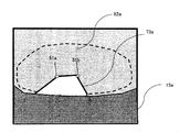
- FIG. 6 shows a procedure for setting the processing target area that is performed in advance before the area is specified by the reference processing target area setting unit 80.
- a processing target area is set for an input image 20a photographed by the camera 6a.
- the processing target region 82a is generated based on the closed region 81a.
- the processing target area may be automatically set by image processing by using contour information or other tools.
- a tool that automatically sets a road surface or the like extracted from an image as a processing target area may be set.
- the processing target area 82a is generated, the method is not particularly limited.
- the setting of the processing target area may be, for example, a closed area surrounded so as to include the entire ground, or a closed area surrounding a part of the ground.
- the processing target area is set only for the image 20a here, it goes without saying that it may be set for the other images 20b, 20c, and 20d.
- the shadow contour extraction unit 40 extracts a contour (shadow contour) of a region that can be regarded as a shadow of the dump truck 1 in the processing target region determined and set by the reference processing target region setting unit 80 based on the feature amount of the image.
- the “area that can be regarded as the shadow of the dump truck 1” does not have to coincide with the actual shadow area of the dump truck 1, and includes an area that is recognized as a shadow of the dump truck 1 because of image processing.
- the outline of the black vehicle may be regarded as the shadow of the dump truck 1.
- the shadow contour extraction unit 40 performs shadow contour extraction using one image synthesized by the image synthesis unit 35 as one frame.
- FIG. 7 shows specific functions provided in the shadow outline extraction unit 40 according to the present embodiment.
- the shadow contour extraction unit 40 includes a processing target region image creation unit 41, a shadow presence / absence determination unit 42, a shadow region extraction unit 43, a shadow region outline image creation unit 44, an expanded image creation unit 45, a shadow contour. It functions as the image creation unit 46.
- the processing target area image creation unit 41 a creates a closed area set as a processing target area by the reference processing target area setting unit 80 in the image stored in the image storage unit 30. As a result, the subsequent processing is limited to the closed region.
- the shadow presence / absence determination unit 42 determines the presence / absence of a shadow in the processing target region, and if it is determined that there is a shadow, the shadow region extraction unit 43 extracts the shadow region. Details of the shadow presence / absence determination unit 42 will be described in detail with reference to FIG.
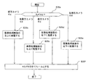
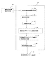
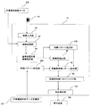
- FIG. 8 is a flowchart of processing executed by the shadow presence / absence determining unit 42 and the shadow region extracting unit 43 according to the surrounding monitoring apparatus for a work machine of the present invention.
- the shadow presence / absence determination unit 42 reduces noise by performing a smoothing process on the processing target areas of the images 20a, 20b, 20c, and 20d.
- the shadows are determined.
- a luminance distribution diagram is created in the processing target areas 20b, 20c, and 20d.
- step 42c the shadow presence / absence determination unit 42 checks the luminance distribution diagram created in step 42b, and calculates the area of the portion where the luminance distribution is equal to or greater than a predetermined threshold.
- step 42d it is determined whether or not the calculated area is less than a predetermined value. If the calculated area is less than the predetermined value (including the case where the area is zero), it is determined in step 42e that there is a shadow candidate. On the other hand, if it is determined in step 42d that the calculated area is greater than or equal to the predetermined value, it is determined in step 42k that there is no vehicle shadow, and the process is terminated.
- step 42f the shadow region extraction unit 43 determines a binarization threshold value for extracting a shadow candidate region, creates a binary image, and in step 42g, shapes such as expansion and contraction for the binary image. Process.
- step 42h an area where the area of the dark portion in the binary image is a predetermined value or more is set as a shadow candidate area.
- step 42i the shadow region extraction unit 43 determines whether or not the shadow candidate region is in the vicinity of the own vehicle region. The candidate area is extracted as a shadow area, and the process ends.
- step 42k determines whether there is no own vehicle shadow.
- step 42i the shadow candidate area is located in the vicinity of the own vehicle area, as described in the explanation of FIG. 5, the dark area 90a that becomes the own vehicle shadow is in contact with the part 15a of the work machine main body. It means that.
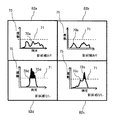
- FIG. 9 is an explanatory diagram of the luminance distribution diagram of step 42b in FIG.
- the frequency 75 indicates the number of pixels in which luminance exists.
- luminance distribution diagrams 70a, 70b, 70c, 70d are created for the images 20a, 20b, 20c, 20d of the cameras 6a, 6b, 6c, 6d.
- step 42c for example, with respect to the luminance distribution diagram 70a of the input image 20a of the camera 6a, the area of a part equal to or greater than a predetermined binarization threshold 71 for extracting a shadow in the reference processing target region is calculated. Since there is no area in the above portion, it is determined in step 42e that “shadow candidate exists”. In this way, when there is a shadow candidate, the luminance distribution diagram 70a does not protrude from the binarization threshold 71 because it is distributed to the luminance of the bright ground and the luminance of the dark shadow.
- the luminance distribution diagram 70c of the input image 20c of the camera 6c has an area in the portion 72c that is equal to or greater than the binarization threshold 71 in the reference processing target region, and the area of the portion 72c is equal to or greater than the threshold. It is determined that there is no vehicle shadow. In this way, when there is no shadow candidate, the luminance of the ground is the most, and this results in a luminance distribution diagram 70 c that protrudes from the binarization threshold 71.
- the area of the portion 72d that is equal to or greater than the binarization threshold 71 in the reference processing target area is equal to or greater than the threshold, and thus is determined to be “no vehicle shadow”.
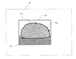
- FIG. 10 is a diagram showing an outline of the vehicle shadow 90a and the vehicle shadow 90b created by the outline image creation unit 44 (see FIG. 7).
- the outline image creation unit 44 sets the outline (contour line) in the area of the own vehicle shadow 90a extracted by the series of processes in FIG. 8 as the outline 73a of the own vehicle shadow 90a.
- an outline (outline) in the area of the vehicle shadow 90b is defined as an outline 73b of the vehicle shadow 90b.
- the expansion image creation unit 45 of the outline image of the shadow region performs expansion processing on the outline (shadow outline) of the outline image created by the outline image creation unit 44.
- the expansion processing by the expansion image creating unit 45 is processing for giving a predetermined width to the outline in the outline image.
- the width may be indirectly specified by specifying the number of expansions.
- the number of expansions is the minimum necessary, and is about 1 to 3 times.
- the shadow outline image creation unit 46 sets the outline image that has been subjected to the expansion process by the expansion image generation unit 45 as a shadow outline image.
- the shadow contour extraction unit 40 extracts the contour of the shadow.
- the feature pattern extraction unit 170 is a part that extracts feature patterns in the images 20a, 20b, 20c, and 20d based on the feature values in the images 20a, 20b, 20c, and 20d. In the present embodiment, only the feature pattern in the processing target region is extracted by the function of the reference processing target region setting unit 80.
- FIG. 11 is a diagram in which the periphery of the feature pattern extraction unit 170 and the shadow outline feature pattern extraction unit 50 is extracted from FIG. 3.
- corner points are used as feature patterns extracted by the feature pattern extraction unit 170.
- the feature pattern extraction unit 170 functions as a corner point extraction unit 51 and a feature pattern extraction unit 52 of a corner point group.
- the feature pattern extracted by the feature pattern extraction unit 170 may be any feature pattern that indicates the shape of the feature detected by extracting the feature of the image based on the feature amount. For example, instead of the corner point Alternatively, a line / contour line (edge) or region may be used.
- the corner point extraction unit 51 extracts corner points in the image by Harris corner detection or the like.
- the corner point group feature pattern extraction unit 52 extracts a corner point group feature pattern including a plurality of corner points. 12 and 13 are explanatory diagrams of processing by the corner point extraction unit 51 and the feature pattern extraction unit 52.
- FIG. In the example of the outline 73a of the own vehicle shadow shown in FIG. 12, the corner point 51a and the corner point 51b (corner point group) existing in the corner portion of the outline 73a are extracted as feature patterns.
- the corner point 51a and the corner point 51b corner point group
- corner points exist at the corners of the outline of the car, so that a plurality of corner points 51A, 51B, 51C, 51D, 51E, 51F, 51G, 51H, 51I, 51J, 51K, 51L, 51M, 51N, and 51P are extracted. That is, these corner point groups 51A to 51P are generated as car feature patterns.
- the shadow contour feature pattern extraction unit 50 extracts feature patterns (for example, corner points) superimposed on the shadow contour. Specifically, the shadow contour feature pattern extraction unit 50 extracts a feature pattern superimposed on the shadow contour image (an image obtained by expanding the shadow outline) extracted by the shadow contour extraction unit 40, and the shadow contour feature pattern is extracted. And
- corner points as feature patterns in the present embodiment is that the number of corner points existing in the shadow tends to be relatively smaller than the number of corner points existing in the detection target object. This is because it is easy to extract.
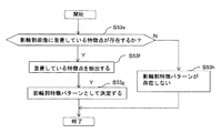
- FIG. 14 is a flowchart of processing executed by the shadow outline feature pattern extraction unit 50.
- the shadow contour feature pattern extraction unit 50 determines whether or not a feature pattern (corner point (feature point)) superimposed on the shadow contour image created by the shadow contour extraction unit 40 exists. . If it is determined in step 53e that a feature pattern to be superimposed on the shadow contour exists, the superimposed feature pattern is extracted in step 53f and determined as a shadow contour feature pattern (step 53g).
- step 53h if there is no feature pattern to be superimposed on the shadow contour in step 53e, it is determined that there is no shadow contour feature pattern (step 53h).
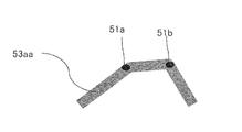
- FIG. 15 is a diagram showing an example of the feature pattern extracted in step 53f of FIG.
- the shadow outline image 53aa in this figure is obtained by expanding the own vehicle shadow 90a. Since the corner point 51a and the corner point 51b are superimposed on the shadow outline image 53aa, the corner point 51a and the corner point 51b are determined as shadow outline feature patterns in step 53g.
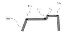
- FIG. 16 is a diagram showing another example of the feature pattern extracted in step 53f of FIG.
- the shadow outline image 53bb in this figure is an expansion of the own vehicle shadow 90b. Since the corner point 51e, the corner point 51f, the corner point 51g, and the corner point 51h are superimposed on the shadow outline image 53bb, the corner point 51e, the corner point 51f, the corner point 51g, and the corner point 51h are used as shadow outline feature patterns. It is determined.
- FIG. 17 is a diagram showing still another example of the feature pattern extracted in step 53f of FIG.
- a black car enters the own vehicle shadow 90b
- the car is also regarded as a shadow
- the inflated image creation unit 45 performs the shadow region outline image S53a created by the shadow region outline image creation unit 44 (see FIG. 7).
- An image 53dd having been subjected to the expansion process a set number of times is created.
- corner points (feature patterns) superimposed on the image 53dd in addition to the corner points 51e on the shadow outline, the corner points 51A, 51B, 51C, 51D, 51E, 51F, 51G, 51H, 51P are extracted, and these are extracted as shadow outline feature patterns.
- the shadow contour feature pattern mask unit 60 creates a region where the feature pattern (shadow contour feature pattern) superimposed on the shadow contour is expanded, and excludes the region (mask region) from the processing target region. Further, since the shadow outline feature pattern is extracted and excluded, not only the false notification of the shadow can be reduced, but also the processing area in the image processing can be optimized. When the mask area of the shadow outline feature pattern mask unit 60 is displayed on the display device 100, the operator of the work machine can monitor the surroundings of the work machine without being affected by the false notification of the shadow even when the work machine is stopped or moved. Is possible.
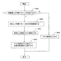
- FIG. 18 is a flowchart of processing executed by the shadow outline feature pattern mask unit 60.
- the shadow contour feature pattern mask unit 60 determines whether or not a feature pattern superimposed on the shadow contour exists.
- step 60b a process of expanding the extracted feature pattern a predetermined number of times (about several times) is performed.
- the expansion process is performed by expanding the feature pattern several times.
- the corner detection of Harris is used, the feature pattern is extracted by one pixel, so that the feature pattern is expanded so as to be a block having a diameter of about 5 to 10 pixels. That's fine.
- step 60c the expanded area is determined as a mask area
- step 60d a process for excluding the mask area from the process target area is performed using the mask area as a mask portion.
- step 60e determines whether there is no mask area.
- FIG. 19 is a diagram showing an example of an image in which the shadow outline feature pattern mask unit 60 is expanded a predetermined number of times (about several times) in step 60b at the corner points 51a and 51b in FIG.
- the corner point 51a and the corner point 51b which are characteristic patterns on the shadow outline, are expanded about several times in eight or four directions, a point 51aa in which the corner point 51a is expanded is generated.
- a point 51bb in which 51b is expanded is generated.
- the areas 51aa and 51bb are excluded from the processing target area (area where obstacle detection is performed by the object detection unit 180) as a mask part.
- the contour of the shadow is extracted at each sampling interval regardless of the complexity of the shape of the own vehicle shadow, and the feature pattern ( Since the regions 51aa and 51bb) are excluded from the obstacle detection targets by the shadow outline feature pattern mask unit 60, it is possible to prevent the vehicle shadow from being erroneously recognized as an obstacle (shadow false report).
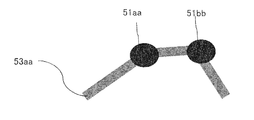
- FIG. 20 is a diagram illustrating an image example in which the shadow outline feature pattern mask unit 60 has expanded the corner point 51e, the corner point 51f, the corner point 51g, and the corner point 51h in FIG. 16 a predetermined number of times (about several times) in step 60b. .
- the corner point 51e which is a feature pattern on the shadow outline
- expansion processing several times in eight or four directions
- an expanded point 51ee is generated.
- the corner points 51ff, 51gg, and 51hh are similarly expanded, and the corner points 51ee, 51ff, 51gg, and 51hh are excluded from the processing target region as mask portions.
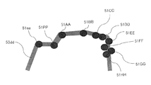
- the shadow outline feature pattern mask unit 60 expands the corner point 51e, corner points 51A, 51B, 51C, 51D, 51E, 51F, 51G, 51H, and 51P of FIG. 17 a predetermined number of times (about several times) in step 60b.
- FIG. When the corner point 51A, which is a feature pattern on the shadow contour, is subjected to expansion processing about several times in eight or four directions, an expanded point 51AA is generated.
- the corner point 51e, the corner points 51B, 51C, 51D, 51E, 51F, 51G, 51H, and 51P are similarly expanded, and the corner points 51ee, 51AA, the corner points 51BB, 51CC, 51DD, 51EE, 51FF, and 51GG are performed.
- 51HH, 51PP are excluded from the processing target area using the mask portion.
- the object detection unit 180 uses the corner point 51I, the corner point 51J, the corner point 51K, the corner point 51L, the corner point 51M, and the corner point 51N to detect an obstacle (a car in the example of FIG. 17). It can be detected immediately.
- the illustrated object is merely an example, and it is needless to say that other obstacles (for example, people) in the vehicle can be detected in the same manner.
- the shadow boundary pattern stored in advance as in the prior art is used. Since it is possible to extract the vehicle shadow reflected in the image from at least one image captured by the camera 6 without reference and without using any color component, erroneous recognition of the vehicle shadow is reduced. As a result, processing speed and work efficiency are improved.
- FIG. 22 is a diagram showing an example of a screen in which the area masked by the shadow outline feature pattern mask unit 60 is displayed on the display device 100 in the scene combined by the image combining unit 35.
- a scene in which the input image 20a of the camera 6a, the input image 20b of the camera 6b, the input image 20c of the camera 6c, and the input image 20d of the camera 6d are combined by the image combining unit 35 is displayed on the display device 100.
- corner points 51aa and 51bb are displayed as feature patterns excluded from the processing target, and corner points 51ee, 51ff, 51gg and 51hh are displayed on the input image 20b.
- the processing target area (obstacle detection target area) from which the shadow contour feature pattern is excluded becomes obvious at a glance. Can check the processing target area in real time.
- FIGS. 23 and 24 when displayed in a bird's-eye view around the dump truck 1, the driver can grasp the front / rear / right / left situation with a sense of direction from the driver's cab 7 and a sense of incongruity. Thus, it is possible to instantaneously determine a region (feature pattern) excluded from the object detection target.
- FIG. 23 and FIG. 24 are examples in which the front portion of the dump truck 1 is displayed on the upper side, and the cab 7 is displayed at the upper left position of the dump truck 1.
- FIG. 23 is a diagram illustrating an example of a screen in which an area masked by the shadow outline feature pattern mask unit 60 is displayed on the display device 100 as an overhead image 110.
- the display device 100 displays the display area 100 so as to extend from the periphery of the dump truck 1 to a distant distance (about 12 m).
- the overhead image 20aa of the input image 20a, the overhead image 20bb of the input image 20b, the overhead image 20cc of the input image 20c, and the overhead image 20dd of the input image 20d are processing target areas, and are excluded from the processing target of the overhead image 20aa.
- Corner points 51aa, 51bb are displayed, and corner points 51ee, 51ff, 51gg, 51hh excluded from the processing target of the overhead image 20bb are displayed.
- the graphic displayed in the center of the display device 100 shows the dump truck 1, and other graphic may be displayed as long as it shows the dump truck 1 in addition to the illustrated graphic.
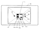
- FIG. 24 is a diagram illustrating an example of a screen in which an area masked by the shadow outline feature pattern mask unit 60 is displayed on the display device 100 as an overhead image 110.
- the display area is limited to a range relatively short (about 5 m) from the periphery of the dump truck 1 and is displayed on the display device 100.
- a black car has entered the own vehicle shadow 90b in the overhead image 20bb of the input image 6bb, and corner points 51ee, 51AA, 51BB, 51CC, 51DD, 51EE excluded from the processing target of the overhead image 20bb.
- 51FF, 51GG, and 51HH are displayed.
- the object detection unit 180 detects the black car as an obstacle based on the remaining feature pattern of the black car, and the warning display 190 indicating that the obstacle is approaching the dump truck 1 is displayed on the display screen 110. Is displayed.
- the illustrated warning display 190 is a rectangle defined so as to be substantially in contact with the outer shape of the feature pattern of the obstacle.
- the warning display 190 displayed on the screen of the display device 100 allows the operator to easily access the obstacle. I can recognize it.
- the shape of the warning display 190 may be a graphic other than a rectangle, a color may be added to the graphic, or the shape or color may be changed over time.
- the display device 100 plays the role of a notification device for notifying that an obstacle has been detected by the object detection unit 180.
- a warning light may be used.
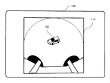
- FIG. 25 is a diagram showing an example of the display screen of the display device 100.
- the example of this figure is an example in which the bird's-eye view image 110 synthesized by the image synthesizing unit 35 and the raw image (through image) 111 taken by the rear camera 6c are displayed in parallel.
- the front part of the truck 1 is displayed on the upper side, and the cab 7 is displayed on the upper left of the dump truck 1.
- the driver can discriminate the rear obstacle (the vehicle 105) without a sense of incongruity based on the familiar camera image.
- a warning display 190 is displayed on both the overhead image 110 and the through image 211, and the driver can easily grasp the approach of the vehicle 105.
- FIG. 26 is a diagram showing an example of the display screen of the display device 100.
- the range of a relatively short distance (about 5 m) from the periphery of the dump truck 1 is displayed on the display device 100 with respect to the overhead image 112 synthesized by the image synthesis unit 35.
- the figure 1a showing the dump truck 1 is displayed larger than the case of FIG. 25 following the display range, the front part of the dump truck 1a is displayed on the right side in the image, and the cab 7 is on the upper right of the display screen. Is displayed. Since the display range is limited to the vicinity of the dump truck 1 and the obstacle (the vehicle 105) existing near the dump truck 1 is displayed large, the operator is the most dangerous obstacle existing near the dump truck 1. Objects can be clearly identified.
- FIG. 27 is a diagram illustrating an example of a display screen of the display device 100.
- a range of a medium distance (about 8 m) from the periphery of the dump truck 1 is displayed on the display device 100.
- a graphic 1b showing the dump truck 1 is displayed smaller than the case of FIG. 26 following the display range.
- FIG. 28 is a diagram showing an example of the display screen of the display device 100.
- a range of a long distance (about 12 m) from the periphery of the dump truck 1 is displayed on the display device 100.
- the figure 1c showing the dump truck 1 is displayed smaller than the case of FIG. 27 following the display range.
- the display range is set to a long distance, the driver can discriminate even an obstacle (vehicle 105) existing at a long distance from the dump truck 1.
- FIG. 29 is a diagram illustrating an example of a display screen of the display device 100.
- the through image 116 of the right side camera 6b and the through image 115 of the left side camera 6d are displayed in parallel.
- the left and right through images 116 and 115 are displayed in this way, it becomes easy to distinguish obstacles existing on the left and right of the dump truck 1, so that it is easy to find obstacles when the dump truck 1 turns left and right.
- FIG. 30 is a diagram illustrating an example of a display screen of the display device 100.
- a through image 117 of the rear camera 6c is displayed.
- the rear through image 117 is displayed in this way, it is easy to find the most difficult obstacle to be found behind the dump truck 1.
- FIG. 31 shows another example of the overall configuration of the work machine surrounding monitoring apparatus of the present invention.
- a work machine shape data definition unit 201 is a part in which shape data of the work machine is defined based on the specifications of the work machine.
- the feature pattern storage unit 200 extracts shape data (appearance shape) defined by the work machine shape data definition unit 201 based on the specifications of the work machine, and indicates the extracted shape data of the work machine. Store as a feature pattern.
- the appearance shape (shape data) here includes the total length, the full width, the total height, the appearance unevenness state, etc. of the work machine, and may be other information as long as it is information related to the shape of the vehicle shadow.
- the shadow contour feature pattern extraction unit 50 shadows the feature pattern superimposed on the shadow contour image while referring to the shadow contour image obtained by the shadow contour extraction unit 40 and the shape data stored in the feature pattern storage unit 200.
- the contour feature pattern is determined.
- the shadow outline feature pattern extraction unit 50 performs pattern matching between the corner point group extracted by the feature pattern extraction unit 170 and the shape data stored in the feature pattern storage unit 200, and the matching rate between the two is a predetermined value. If the two are similar to each other, the corner point group may be extracted as a feature pattern of the shadow outline.
- the image storage unit 30 once inputs an image from the image input unit 20 when the work machine is started up. Thereafter, the image storage unit 30 checks the operating status of the work machine obtained based on the work machine operation data 202, and the work machine When not stopped (when operating), an image is input from the image input unit 20, and when the work machine is stopped, input of an image from the image input unit 20 is interrupted. This makes it possible to sample images from the image input unit 20 at different sampling intervals depending on the operating status of the work machine. As a result, the image processing may be performed based on the minimum necessary input image, and the time can be reduced and the processing can be optimized.
- the image from the image input unit 20 may be sampled at a constant sampling interval.
- FIG. 32 is another flowchart of processing executed by the shadow presence / absence determining unit 42 and the shadow region extracting unit 43 according to the surrounding monitoring apparatus for a work machine of the present invention.
- a color component is extracted from the reference processing target area of the image smoothed in step 42a.
- step 42cc it is determined whether or not the reference processing target area is composed only of areas where color components exist.
- step 42cc If it is determined in step 42cc that there is an area where no color component exists, the process proceeds to step 42dd to extract an area where the color component does not exist.
- step 42ee a binarization threshold value for extracting a shadow candidate area is determined, a binary image is created, and the processes in and after step 42g are performed.
- step 42cc determines whether or not the region where the color component exists is present. If it is determined in step 42cc that only the region where the color component exists is present, the processing of step 42k is performed. As described above, when the color component can be used for the determination of the shadow, the accuracy of determining whether or not it is a shadow can be improved.
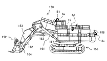
- FIG. 33 is a side view of a so-called loader type large hydraulic excavator, which is one of the work machines to which the present invention is applied.
- This hydraulic excavator is connected to a lower traveling body 155, an upper revolving body 156 provided on the upper portion of the lower traveling body 155 via a swivel bearing 157 so as to be able to swivel, and the upper revolving body 156 so as to be able to move up and down.
- An articulated front working machine 158 is provided to a so-called loader type large hydraulic excavator, which is one of the work machines to which the present invention is applied.
- This hydraulic excavator is connected to a lower traveling body 155, an upper revolving body 156 provided on the upper portion of the lower traveling body 155 via a swivel bearing 157 so as to be able to swivel, and the upper revolving body 156 so as to be able to move up and down.
- the bucket 152 provided in the multi-joint type front working machine 158 is disposed so that the opening is directed forward in a grounded state, and the bucket opening / closing cylinder 164 is mounted on the bucket 152 as illustrated. Further, the boom cylinder 161, bucket cylinder 162, arm cylinder 163, and bucket opening / closing cylinder 164 perform boom raising / lowering, arm pushing / pulling, bucket crowding / dumping, and bucket closing / releasing by an expansion / contraction operation. .
- the above-described components including a plurality of cameras for example, the cameras 6a, 6c, and 6d in the figure
- the image processing device 10 are mounted on the hydraulic excavator thus configured.
- a surrounding monitoring device can be configured in the same manner as described above.
- the present invention is not limited to the above-described embodiments, and includes various modifications within the scope not departing from the gist thereof.
- the present invention is not limited to the one having all the configurations described in the above embodiments, and includes a configuration in which a part of the configuration is deleted.
- part of the configuration according to one embodiment can be added to or replaced with the configuration according to another embodiment.
- each configuration relating to the image processing apparatus and the functions and execution processing of each configuration are realized by hardware (for example, logic for executing each function is designed by an integrated circuit). You may do it.
- the configuration related to the image processing apparatus may be a program (software) that realizes each function related to the configuration of the image processing apparatus by being read and executed by an arithmetic processing apparatus (for example, a CPU).
- Information related to the program can be stored in, for example, a semiconductor memory (flash memory, SSD, etc.), a magnetic storage device (hard disk drive, etc.), a recording medium (magnetic disk, optical disc, etc.), and the like.
- 6a, 6b, 6c, 6d ... camera, 30 ... image storage unit, 35 ... image composition unit, 40 ... shadow contour extraction unit, 50 ... shadow contour feature pattern extraction unit, 60 ... shadow contour feature pattern mask unit, 80 ... reference Processing target area setting unit, 100 ... display device, 170 ... feature pattern extraction unit, 180 ... object detection
Landscapes
- Engineering & Computer Science (AREA)
- Physics & Mathematics (AREA)
- General Physics & Mathematics (AREA)
- Multimedia (AREA)
- Theoretical Computer Science (AREA)
- Computer Vision & Pattern Recognition (AREA)
- Mechanical Engineering (AREA)
- Mining & Mineral Resources (AREA)
- Civil Engineering (AREA)
- General Engineering & Computer Science (AREA)
- Structural Engineering (AREA)
- Signal Processing (AREA)
- Image Analysis (AREA)
- Image Processing (AREA)
- Closed-Circuit Television Systems (AREA)
- Traffic Control Systems (AREA)
Priority Applications (3)
| Application Number | Priority Date | Filing Date | Title |
|---|---|---|---|
| EP15782523.3A EP3136341B1 (en) | 2014-04-24 | 2015-03-04 | Surroundings monitoring system for working machine |
| US15/124,123 US10160383B2 (en) | 2014-04-24 | 2015-03-04 | Surroundings monitoring system for working machine |
| CN201580011783.6A CN106062823B (zh) | 2014-04-24 | 2015-03-04 | 作业机械的周围监视装置 |
Applications Claiming Priority (2)
| Application Number | Priority Date | Filing Date | Title |
|---|---|---|---|
| JP2014-090679 | 2014-04-24 | ||
| JP2014090679A JP6178280B2 (ja) | 2014-04-24 | 2014-04-24 | 作業機械の周囲監視装置 |
Publications (1)
| Publication Number | Publication Date |
|---|---|
| WO2015163015A1 true WO2015163015A1 (ja) | 2015-10-29 |
Family
ID=54332186
Family Applications (1)
| Application Number | Title | Priority Date | Filing Date |
|---|---|---|---|
| PCT/JP2015/056432 Ceased WO2015163015A1 (ja) | 2014-04-24 | 2015-03-04 | 作業機械の周囲監視装置 |
Country Status (5)
| Country | Link |
|---|---|
| US (1) | US10160383B2 (enExample) |
| EP (1) | EP3136341B1 (enExample) |
| JP (1) | JP6178280B2 (enExample) |
| CN (1) | CN106062823B (enExample) |
| WO (1) | WO2015163015A1 (enExample) |
Cited By (2)
| Publication number | Priority date | Publication date | Assignee | Title |
|---|---|---|---|---|
| CN107925745A (zh) * | 2015-11-30 | 2018-04-17 | 住友重机械工业株式会社 | 施工机械用周边监视系统 |
| EP4414506A4 (en) * | 2021-11-17 | 2025-03-19 | Kobelco Construction Machinery Co., Ltd. | SURVEILLANCE ZONE ADJUSTMENT SYSTEM |
Families Citing this family (24)
| Publication number | Priority date | Publication date | Assignee | Title |
|---|---|---|---|---|
| JP6572156B2 (ja) * | 2016-03-02 | 2019-09-04 | 株式会社神戸製鋼所 | 建設機械の干渉防止装置 |
| JP6729146B2 (ja) * | 2016-08-03 | 2020-07-22 | コベルコ建機株式会社 | 障害物検出装置 |
| JP6599835B2 (ja) * | 2016-09-23 | 2019-10-30 | 日立建機株式会社 | 鉱山用作業機械、障害物判別装置、及び障害物判別方法 |
| JP6855254B2 (ja) * | 2017-01-12 | 2021-04-07 | 株式会社デンソーテン | 画像処理装置、画像処理システム、及び、画像処理方法 |
| KR102449834B1 (ko) * | 2017-02-17 | 2022-09-29 | 스미도모쥬기가이고교 가부시키가이샤 | 작업기계용 주변감시 시스템 |
| JP6589945B2 (ja) * | 2017-07-14 | 2019-10-16 | コベルコ建機株式会社 | 建設機械 |
| CN110998669B (zh) * | 2017-08-08 | 2023-12-08 | 索尼公司 | 图像处理装置和方法 |
| JP6969983B2 (ja) * | 2017-11-10 | 2021-11-24 | 株式会社小松製作所 | ダンプトラック |
| JP6900897B2 (ja) * | 2017-12-25 | 2021-07-07 | コベルコ建機株式会社 | 建設機械の障害物検出装置 |
| KR102659075B1 (ko) * | 2018-03-26 | 2024-04-18 | 스미토모 겐키 가부시키가이샤 | 쇼벨 |
| JP7160606B2 (ja) * | 2018-09-10 | 2022-10-25 | 株式会社小松製作所 | 作業機械の制御システム及び方法 |
| US11620736B2 (en) * | 2018-10-29 | 2023-04-04 | Pfu Limited | Image processing device, control method, and control program |
| GB2582323B (en) * | 2019-03-19 | 2022-02-09 | Jaguar Land Rover Ltd | Image processing system and method |
| CN110099268B (zh) * | 2019-05-28 | 2021-03-02 | 吉林大学 | 色彩自然匹配与显示区自然融合的盲区透视化显示方法 |
| US10949685B2 (en) | 2019-07-22 | 2021-03-16 | Caterpillar Inc. | Excluding a component of a work machine from a video frame based on motion information |
| JP7310526B2 (ja) * | 2019-10-14 | 2023-07-19 | 株式会社デンソー | 障害物識別装置および障害物識別プログラム |
| US11320830B2 (en) | 2019-10-28 | 2022-05-03 | Deere & Company | Probabilistic decision support for obstacle detection and classification in a working area |
| JP7065068B2 (ja) * | 2019-12-13 | 2022-05-11 | 本田技研工業株式会社 | 車両周囲監視装置、車両、車両周囲監視方法およびプログラム |
| CN111462220B (zh) * | 2020-04-03 | 2025-01-24 | 深圳前海微众银行股份有限公司 | 待侦测物体阴影面积提取方法、装置、设备及介质 |
| CN115298394B (zh) * | 2020-05-29 | 2025-02-25 | 日立建机株式会社 | 作业机械 |
| JP6991285B2 (ja) * | 2020-07-28 | 2022-01-12 | 株式会社クボタ | 作業車 |
| JP7739042B2 (ja) | 2021-05-14 | 2025-09-16 | ヤンマーホールディングス株式会社 | 安全監視システムの制御方法及び安全監視システム |
| US20230306707A1 (en) * | 2022-03-28 | 2023-09-28 | Hl Klemove Corp. | Around view monitoring system and the method thereof |
| US20250044764A1 (en) * | 2023-08-01 | 2025-02-06 | Caterpillar Inc. | Nuisance condition detection system |
Citations (2)
| Publication number | Priority date | Publication date | Assignee | Title |
|---|---|---|---|---|
| JP2008165765A (ja) * | 2006-12-29 | 2008-07-17 | Alpine Electronics Inc | 車両側面画像取得方法及び装置、車灯誤識別検出方法及び安全運転予測方法 |
| JP2011209896A (ja) * | 2010-03-29 | 2011-10-20 | Nec Corp | 障害物検知装置、障害物検知方法及び障害物検知プログラム |
Family Cites Families (17)
| Publication number | Priority date | Publication date | Assignee | Title |
|---|---|---|---|---|
| AU2003225228A1 (en) * | 2002-05-03 | 2003-11-17 | Donnelly Corporation | Object detection system for vehicle |
| US7084386B2 (en) * | 2003-05-02 | 2006-08-01 | International Business Machines Corporation | System and method for light source calibration |
| JP2005043324A (ja) * | 2003-07-25 | 2005-02-17 | Matsushita Electric Ind Co Ltd | 路面損傷状態点検方法及び路面損傷位置の特定方法 |
| US7720580B2 (en) * | 2004-12-23 | 2010-05-18 | Donnelly Corporation | Object detection system for vehicle |
| US20090309710A1 (en) * | 2005-04-28 | 2009-12-17 | Aisin Seiki Kabushiki Kaisha | Vehicle Vicinity Monitoring System |
| JP4956915B2 (ja) * | 2005-05-20 | 2012-06-20 | 日産自動車株式会社 | 映像表示装置及び映像表示方法 |
| JP4809019B2 (ja) * | 2005-08-31 | 2011-11-02 | クラリオン株式会社 | 車両用障害物検出装置 |
| JP4674179B2 (ja) * | 2006-03-30 | 2011-04-20 | 株式会社デンソーアイティーラボラトリ | 影認識方法及び影境界抽出方法 |
| JP4853444B2 (ja) * | 2007-09-28 | 2012-01-11 | 株式会社デンソー | 移動物体検出装置 |
| JP4876118B2 (ja) * | 2008-12-08 | 2012-02-15 | 日立オートモティブシステムズ株式会社 | 立体物出現検知装置 |
| CN102158684A (zh) * | 2010-02-12 | 2011-08-17 | 王炳立 | 具有图像增强功能的自适应场景图像辅助系统 |
| JP2011205513A (ja) * | 2010-03-26 | 2011-10-13 | Aisin Seiki Co Ltd | 車両周辺監視装置 |
| JP5722127B2 (ja) * | 2011-06-07 | 2015-05-20 | 株式会社小松製作所 | 作業車両の周辺監視装置 |
| US9497422B2 (en) * | 2011-06-07 | 2016-11-15 | Komatsu Ltd. | Perimeter monitoring device for work vehicle |
| JP5781978B2 (ja) * | 2012-05-22 | 2015-09-24 | 株式会社小松製作所 | ダンプトラック |
| KR101439052B1 (ko) * | 2013-09-05 | 2014-09-05 | 현대자동차주식회사 | 장애물 검출 장치 및 방법 |
| CN103544487B (zh) | 2013-11-01 | 2019-11-22 | 扬州瑞控汽车电子有限公司 | 基于单目视觉的前车识别方法 |
-
2014
- 2014-04-24 JP JP2014090679A patent/JP6178280B2/ja not_active Expired - Fee Related
-
2015
- 2015-03-04 EP EP15782523.3A patent/EP3136341B1/en active Active
- 2015-03-04 CN CN201580011783.6A patent/CN106062823B/zh not_active Expired - Fee Related
- 2015-03-04 WO PCT/JP2015/056432 patent/WO2015163015A1/ja not_active Ceased
- 2015-03-04 US US15/124,123 patent/US10160383B2/en active Active
Patent Citations (2)
| Publication number | Priority date | Publication date | Assignee | Title |
|---|---|---|---|---|
| JP2008165765A (ja) * | 2006-12-29 | 2008-07-17 | Alpine Electronics Inc | 車両側面画像取得方法及び装置、車灯誤識別検出方法及び安全運転予測方法 |
| JP2011209896A (ja) * | 2010-03-29 | 2011-10-20 | Nec Corp | 障害物検知装置、障害物検知方法及び障害物検知プログラム |
Non-Patent Citations (2)
| Title |
|---|
| HITOSHI SAJI ET AL.: "Eisei Gazo o Mochiita Doro Konzatsu Jokyo no Kaiseki", IMAGE LAB, vol. 23, no. 12, 10 December 2012 (2012-12-10), pages 13 - 17, XP008185043 * |
| See also references of EP3136341A4 * |
Cited By (3)
| Publication number | Priority date | Publication date | Assignee | Title |
|---|---|---|---|---|
| CN107925745A (zh) * | 2015-11-30 | 2018-04-17 | 住友重机械工业株式会社 | 施工机械用周边监视系统 |
| CN107925745B (zh) * | 2015-11-30 | 2020-09-08 | 住友重机械工业株式会社 | 施工机械用周边监视系统 |
| EP4414506A4 (en) * | 2021-11-17 | 2025-03-19 | Kobelco Construction Machinery Co., Ltd. | SURVEILLANCE ZONE ADJUSTMENT SYSTEM |
Also Published As
| Publication number | Publication date |
|---|---|
| JP2015210602A (ja) | 2015-11-24 |
| CN106062823B (zh) | 2019-04-02 |
| JP6178280B2 (ja) | 2017-08-09 |
| EP3136341A4 (en) | 2018-01-03 |
| US10160383B2 (en) | 2018-12-25 |
| US20170018070A1 (en) | 2017-01-19 |
| CN106062823A (zh) | 2016-10-26 |
| EP3136341A1 (en) | 2017-03-01 |
| EP3136341B1 (en) | 2020-03-04 |
Similar Documents
| Publication | Publication Date | Title |
|---|---|---|
| JP6178280B2 (ja) | 作業機械の周囲監視装置 | |
| CN105339061B (zh) | 周边监视系统、作业车辆以及周边监视方法 | |
| EP2937811B1 (en) | Vehicle peripheral obstacle notification system | |
| JP5902990B2 (ja) | 自走式産業機械の画像処理装置 | |
| JP5995899B2 (ja) | 自走式産業機械の画像処理装置 | |
| AU2014213529B2 (en) | Image display system | |
| CN105474635A (zh) | 作业机械的周围监视装置 | |
| CN106436545A (zh) | 机动建筑机械和用于显示机动建筑机械周围环境的方法 | |
| JP6542539B2 (ja) | 車両用進入可否判定装置 | |
| CN109070824A (zh) | 显示控制装置、显示控制方法以及程序 | |
| CN110619674B (zh) | 用于事故和警情场景还原的三维增强现实设备及方法 | |
| WO2014073571A1 (ja) | 自走式産業機械の画像処理装置および自走式産業機械の画像処理方法 | |
| CN105549013A (zh) | 用于汽车雷达成像的物体边界检测 | |
| JP6420657B2 (ja) | 作業機械およびその周囲監視装置 | |
| KR20220014118A (ko) | 적재 불량 트럭 단속 시스템 | |
| CN109977844A (zh) | 一种基于图像识别机动车礼让行人控制系统及控制方法 | |
| JP6405422B2 (ja) | 作業機械の周囲監視装置 | |
| JP4674179B2 (ja) | 影認識方法及び影境界抽出方法 | |
| CN112801056A (zh) | 一种基于局部图像分类的渣土车顶盖状态确定方法及系统 | |
| CN118405134A (zh) | 一种积水道路驾驶辅助方法、装置、车辆、存储介质及程序产品 | |
| US11173785B2 (en) | Operator assistance vision system | |
| JP6796518B2 (ja) | 移動物体検知システム | |
| JP6868996B2 (ja) | 障害物検知システム及び建設機械 | |
| US20170307362A1 (en) | System and method for environment recognition | |
| EA045770B1 (ru) | Устройство для анализа полезного груза, транспортируемого в грузовом контейнере транспортного средства |
Legal Events
| Date | Code | Title | Description |
|---|---|---|---|
| 121 | Ep: the epo has been informed by wipo that ep was designated in this application |
Ref document number: 15782523 Country of ref document: EP Kind code of ref document: A1 |
|
| REEP | Request for entry into the european phase |
Ref document number: 2015782523 Country of ref document: EP |
|
| WWE | Wipo information: entry into national phase |
Ref document number: 2015782523 Country of ref document: EP |
|
| WWE | Wipo information: entry into national phase |
Ref document number: 15124123 Country of ref document: US |
|
| NENP | Non-entry into the national phase |
Ref country code: DE |