WO2015162728A1 - 圧延システム - Google Patents
圧延システム Download PDFInfo
- Publication number
- WO2015162728A1 WO2015162728A1 PCT/JP2014/061448 JP2014061448W WO2015162728A1 WO 2015162728 A1 WO2015162728 A1 WO 2015162728A1 JP 2014061448 W JP2014061448 W JP 2014061448W WO 2015162728 A1 WO2015162728 A1 WO 2015162728A1
- Authority
- WO
- WIPO (PCT)
- Prior art keywords
- temperature
- induction heating
- steel material
- heating device
- speed
- Prior art date
- Legal status (The legal status is an assumption and is not a legal conclusion. Google has not performed a legal analysis and makes no representation as to the accuracy of the status listed.)
- Ceased
Links
Images




Classifications
-
- B—PERFORMING OPERATIONS; TRANSPORTING
- B21—MECHANICAL METAL-WORKING WITHOUT ESSENTIALLY REMOVING MATERIAL; PUNCHING METAL
- B21B—ROLLING OF METAL
- B21B37/00—Control devices or methods specially adapted for metal-rolling mills or the work produced thereby
- B21B37/74—Temperature control, e.g. by cooling or heating the rolls or the product
-
- B—PERFORMING OPERATIONS; TRANSPORTING
- B21—MECHANICAL METAL-WORKING WITHOUT ESSENTIALLY REMOVING MATERIAL; PUNCHING METAL
- B21B—ROLLING OF METAL
- B21B1/00—Metal-rolling methods or mills for making semi-finished products of solid or profiled cross-section; Sequence of operations in milling trains; Layout of rolling-mill plant, e.g. grouping of stands; Succession of passes or of sectional pass alternations
- B21B1/22—Metal-rolling methods or mills for making semi-finished products of solid or profiled cross-section; Sequence of operations in milling trains; Layout of rolling-mill plant, e.g. grouping of stands; Succession of passes or of sectional pass alternations for rolling plates, strips, bands or sheets of indefinite length
- B21B1/24—Metal-rolling methods or mills for making semi-finished products of solid or profiled cross-section; Sequence of operations in milling trains; Layout of rolling-mill plant, e.g. grouping of stands; Succession of passes or of sectional pass alternations for rolling plates, strips, bands or sheets of indefinite length in a continuous or semi-continuous process
- B21B1/26—Metal-rolling methods or mills for making semi-finished products of solid or profiled cross-section; Sequence of operations in milling trains; Layout of rolling-mill plant, e.g. grouping of stands; Succession of passes or of sectional pass alternations for rolling plates, strips, bands or sheets of indefinite length in a continuous or semi-continuous process by hot-rolling, e.g. Steckel hot mill
-
- B—PERFORMING OPERATIONS; TRANSPORTING
- B21—MECHANICAL METAL-WORKING WITHOUT ESSENTIALLY REMOVING MATERIAL; PUNCHING METAL
- B21B—ROLLING OF METAL
- B21B37/00—Control devices or methods specially adapted for metal-rolling mills or the work produced thereby
- B21B37/74—Temperature control, e.g. by cooling or heating the rolls or the product
- B21B37/76—Cooling control on the run-out table
-
- B—PERFORMING OPERATIONS; TRANSPORTING
- B21—MECHANICAL METAL-WORKING WITHOUT ESSENTIALLY REMOVING MATERIAL; PUNCHING METAL
- B21C—MANUFACTURE OF METAL SHEETS, WIRE, RODS, TUBES, PROFILES OR LIKE SEMI-MANUFACTURED PRODUCTS OTHERWISE THAN BY ROLLING; AUXILIARY OPERATIONS USED IN CONNECTION WITH METAL-WORKING WITHOUT ESSENTIALLY REMOVING MATERIAL
- B21C51/00—Measuring, gauging, indicating, counting, or marking devices specially adapted for use in the production or manipulation of material in accordance with subclasses B21B - B21F
-
- C—CHEMISTRY; METALLURGY
- C21—METALLURGY OF IRON
- C21D—MODIFYING THE PHYSICAL STRUCTURE OF FERROUS METALS; GENERAL DEVICES FOR HEAT TREATMENT OF FERROUS OR NON-FERROUS METALS OR ALLOYS; MAKING METAL MALLEABLE, e.g. BY DECARBURISATION OR TEMPERING
- C21D1/00—General methods or devices for heat treatment, e.g. annealing, hardening, quenching or tempering
- C21D1/34—Methods of heating
- C21D1/42—Induction heating
-
- C—CHEMISTRY; METALLURGY
- C21—METALLURGY OF IRON
- C21D—MODIFYING THE PHYSICAL STRUCTURE OF FERROUS METALS; GENERAL DEVICES FOR HEAT TREATMENT OF FERROUS OR NON-FERROUS METALS OR ALLOYS; MAKING METAL MALLEABLE, e.g. BY DECARBURISATION OR TEMPERING
- C21D11/00—Process control or regulation for heat treatments
-
- B—PERFORMING OPERATIONS; TRANSPORTING
- B21—MECHANICAL METAL-WORKING WITHOUT ESSENTIALLY REMOVING MATERIAL; PUNCHING METAL
- B21B—ROLLING OF METAL
- B21B38/00—Methods or devices for measuring, detecting or monitoring specially adapted for metal-rolling mills, e.g. position detection, inspection of the product
- B21B38/006—Methods or devices for measuring, detecting or monitoring specially adapted for metal-rolling mills, e.g. position detection, inspection of the product for measuring temperature
-
- B—PERFORMING OPERATIONS; TRANSPORTING
- B21—MECHANICAL METAL-WORKING WITHOUT ESSENTIALLY REMOVING MATERIAL; PUNCHING METAL
- B21B—ROLLING OF METAL
- B21B45/00—Devices for surface or other treatment of work, specially combined with or arranged in, or specially adapted for use in connection with, metal-rolling mills
- B21B45/004—Heating the product
-
- Y—GENERAL TAGGING OF NEW TECHNOLOGICAL DEVELOPMENTS; GENERAL TAGGING OF CROSS-SECTIONAL TECHNOLOGIES SPANNING OVER SEVERAL SECTIONS OF THE IPC; TECHNICAL SUBJECTS COVERED BY FORMER USPC CROSS-REFERENCE ART COLLECTIONS [XRACs] AND DIGESTS
- Y02—TECHNOLOGIES OR APPLICATIONS FOR MITIGATION OR ADAPTATION AGAINST CLIMATE CHANGE
- Y02P—CLIMATE CHANGE MITIGATION TECHNOLOGIES IN THE PRODUCTION OR PROCESSING OF GOODS
- Y02P10/00—Technologies related to metal processing
- Y02P10/25—Process efficiency
Definitions
- This invention relates to a rolling system provided with an induction heating device.
- an induction heating device has features such as excellent energy saving, rapid heating, good temperature controllability and responsiveness, and a good working environment compared to other heating devices.
- an induction heating device in a rolling line (for example, a hot rolling line)
- a rolling line for example, a hot rolling line
- high speed rolling from the front end to the tail end of the material becomes possible. If the temperature of the tail end of the material is increased by the induction heating device, it is possible to roll even a material that could not be rolled conventionally (for example, a thin and long material). Because of these various advantages, various methods of using an induction heating apparatus have been proposed for each facility and are actually applied.
- Patent Document 1 by heating a material with an induction heating device, the surface temperature of the material immediately after passing through the induction heating device is set to a certain target temperature or more, and the internal temperature of the material is set to a certain target temperature or less.
- the temperature of the material falls within a desired range on the exit side of the finish rolling mill.
- the temperature of the material on the entrance side of the finish mill must be accurately controlled. If the temperature of the material can be accurately controlled on the entry side of the finish rolling mill, the temperature of the material is stabilized on the exit side of the finish rolling mill.
- Patent Document 1 does not disclose specific contents such as how to stabilize the temperature of the material on the entry side of the finish rolling mill. There is a certain distance between the induction heating device and the finish rolling mill, and after passing through the induction heating device, the temperature of the material is reduced by heat conduction inside the material, heat removal to the table roll of the conveyance table, air convection, etc. It will change.
- the objective of this invention is providing the rolling system which can control an induction heating apparatus so that material may become the optimal temperature in the entrance side of a finish rolling mill.
- the rolling system includes an induction heating device that heats a material conveyed by a conveyance table, a first temperature detector that detects a temperature of the material at a first position upstream from the induction heating device, and an induction heating device.
- a finish rolling mill that is provided downstream and rolls the material; a second temperature detector that detects the temperature of the material at a second position downstream of the induction heating device and upstream of the finish rolling mill; and power required for the induction heating device
- a setting power calculation device that generates a temperature distribution pattern in the thickness direction of the material at the first position based on the temperature detected by the first temperature detector.
- a first calculator for calculating the volume average temperature of the material at the second position when the material moves from the first position to the second position based on the temperature distribution pattern generated by the generating means.
- second calculation means for calculating electric power necessary for the induction heating device so that the volume average temperature calculated by the first calculation means follows the target temperature of the material at the second position.
- the means divides the material into nodes in the plate thickness direction, radiant cooling, heat removal by air convection, heat removal to the table roll of the transport table, heat conduction resulting from the temperature difference between adjacent nodes and the amount of heat from the induction heating device The temperature change of each node is calculated based on the change, and the volume average temperature of the material is calculated based on the calculation result.
- the induction heating device can be controlled so that the material has an optimum temperature on the entry side of the finish rolling mill.
- FIG. 1 is a configuration diagram showing a rolling system in Embodiment 1 of the present invention. As an example of the rolling line, a hot rolling line is shown.
- the hot rolling line rolls the steel material 1 while conveying the steel material (material) 1 by the conveyance table 2.
- Reference numeral 3 denotes a table roll provided in the transport table 2.
- the table roll 3 is driven by an electric motor (not shown).
- the steel material 1 is placed on the table roll 3 and is conveyed in a direction corresponding to the rotation direction when the table roll 3 rotates.
- 4 is a speed detector for detecting the speed of the steel material 1 conveyed by the conveyance table 2.
- the speed detector 4 detects the conveyance speed of the steel material 1 based on the rotational power of the table roll 3, for example.
- the speed detection method by the speed detector 4 is not limited to this.
- the speed detector 4 outputs information on the detected speed to the set power calculation device 7 and the power control device 8.
- the rolling of the steel material 1 is performed by, for example, a roughing mill (not shown) and a finish rolling mill 5 provided downstream from the roughing mill.
- the hot rolling line may not be equipped with a roughing mill.
- An induction heating device 6 for heating the steel material 1 is disposed downstream of the rough rolling mill and upstream of the finish rolling mill 5.
- the induction heating device 6 heats the steel material 1 by electromagnetic induction.
- the set power calculation device 7 calculates the power required for the induction heating device 6 and outputs the calculated power pattern to the power control device 8.
- the power control device 8 controls the power supplied to the induction heating device 6 so that the power is supplied to the induction heating device 6 according to the power pattern input from the set power calculation device 7.
- the temperature detector 9 detects the temperature of the steel material 1.
- the temperature detector 9 detects the surface temperature of the steel material 1 passing through a certain position set upstream from the induction heating device 6. Information on the temperature of the steel material 1 detected by the temperature detector 9 is input to the set power calculation device 7.
- the temperature detector 10 detects the temperature of the steel material 1.
- the temperature detector 10 detects the surface temperature of the steel material 1 passing through a certain position set downstream from the induction heating device 6 and upstream from the finish rolling mill 5.
- the temperature detector 10 detects the temperature of the steel material 1 immediately before entering the finish rolling mill 5, for example.
- Information on the temperature of the steel material 1 detected by the temperature detector 10 is input to the set power calculation device 7 and the temperature rise pattern setting determination device 12.
- the temperature detector 11 detects the temperature of the steel material 1.
- the temperature detector 11 detects the surface temperature of the steel material 1 that passes through a certain position set downstream from the finish rolling mill 5.
- the temperature detector 11 detects the temperature of the steel material 1 immediately after leaving the finish rolling mill 5, for example. Information on the temperature of the steel material 1 detected by the temperature detector 11 is input to the temperature rise pattern setting determination device 12.
- the temperature rising pattern setting determining device 12 is a device for a factory worker or the like to determine a temperature rising pattern setting before rolling the steel material 1.
- the information on the temperature rising pattern setting determined by the factory worker or the like is output from the temperature rising pattern setting determining device 12 to the set power calculating device 7.
- the temperature information detected by the temperature detector 10 and the temperature information detected by the temperature detector 11 are input to the temperature rising pattern setting determining device 12 every time rolling is performed.
- the temperature rise pattern setting determination device 12 stores the input temperature information in a storage device (not shown).
- Factory workers and the like refer to temperature information stored in the storage device when determining the temperature rise pattern setting.
- a factory worker etc. determine a temperature rising pattern setting based on the classification of the steel material 1 from a viewpoint of the plate
- the set power calculation device 7 is based on the temperature of the steel material 1 detected by the temperature detector 9, the speed pattern of the steel material 1 calculated or set in advance, and the temperature increase pattern setting input from the temperature increase pattern setting determination device 12. Thus, the power pattern for the induction heating device 6 is calculated.
- the power control device 8 calculates the final output power by correcting the deviation from the speed pattern of the steel material 1 calculated in advance using the actual conveyance speed detected by the speed detector 4.
- FIG. 2 is a flowchart showing the operation of the set power calculation device 7.
- the set power calculation device 7 performs the process shown in FIG. 2, and determines an electric power pattern for appropriately heating the entire length of the steel material 1 by the induction heating device 6.
- the set power calculation device 7 first takes in the temperature rising pattern setting of the steel material 1 at the downstream temperature management position from the temperature rising pattern setting determining device 12 (S1).
- the downstream temperature management position is a position for managing the temperature of the steel material 1.
- the downstream temperature management position is set downstream of the induction heating device 6, for example, on the entry side of the finish rolling mill 5. In the example shown in FIG. 1, the position at which the temperature detector 10 detects the temperature of the steel material 1 is set as the downstream temperature management position.
- the temperature rise pattern setting is defined as the temperature rise (average temperature) from the predicted temperature value (average temperature) of the steel material 1 at the downstream temperature management position. This temperature predicted value is the average temperature of the steel material 1 when heating by the induction heating device 6 is not performed.
- the temperature rise pattern setting taken into the set power calculation device 7 in S1 is information as a deviation.
- the set power calculation device 7 acquires the temperature increase pattern setting for the entire length of the steel material 1 in S1.
- An average temperature means the temperature which calculated
- T va Volume average temperature
- T [i] Temperature of node i
- V i Volume of node i i: Node number (1, 2,..., 2N ⁇ 1) It is.
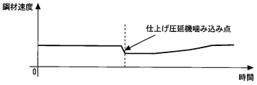
- the set power calculation device 7 captures the speed pattern of the steel material 1 in S2.
- FIG. 3 shows an example of the speed pattern of the steel material 1 immediately below the induction heating device 6 when being transported by the transport table 2.
- the speed pattern of the steel material 1 from the roughing mill (or induction heating device 6) to the finishing mill 5 can be calculated in advance by a simple procedure.
- the speed of the steel material 1 is governed by the speed of the finish rolling mill 5 when the tip is caught in the finish rolling mill 5. For this reason, the speed pattern of the steel material 1 generally changes in the deceleration direction when the tip is bitten by the finishing mill 5. Further, the subsequent speed pattern of the steel material 1 changes in the acceleration direction as the finish rolling mill 5 accelerates.
- the set power calculation device 7 acquires a speed pattern for the entire length of the steel material 1 in S2.
- the set power calculation device 7 takes in the temperature distribution pattern in the plate thickness direction of the steel material 1 at the upstream temperature management position in S3.
- the upstream temperature management position is a position for managing the temperature of the steel material 1.
- the upstream temperature management position is set upstream of the induction heating device 6. In the example shown in FIG. 1, the position where the temperature detector 9 detects the temperature of the steel material 1 is set as the upstream temperature management position.
- the set power calculation device 7 takes in the temperature (actual value) of the steel material 1 measured at the upstream temperature management position in S4. Specifically, the set power calculation device 7 takes in the surface temperature of the steel material 1 detected by the temperature detector 9 as the actual temperature value of the steel material 1 in S4. The set power calculation device 7 acquires the surface temperature for the entire length of the steel material 1 in S4.
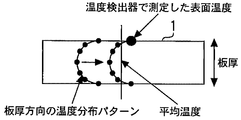
- the set power calculation device 7 generates a temperature distribution pattern in the plate thickness direction of the steel material 1 at the upstream temperature management position using the temperature distribution pattern acquired in S3 and the actual temperature value acquired in S4.
- the temperature distribution pattern generated in S5 is not information as a mere deviation but information that takes into account the actual temperature of the steel material 1.
- FIG. 4 the example of the production
- the set power calculation device 7 is based on the actual temperature value by, for example, matching the temperature of the portion corresponding to the surface of the steel material 1 in the temperature distribution pattern acquired in S3 with the surface temperature detected by the temperature detector 9. Generate a temperature distribution pattern.
- the set power calculation device 7 generates a temperature distribution pattern in the plate thickness direction with respect to the entire length of the steel material 1 in S5.
- the set power calculation device 7 calculates the temperature change of the steel material 1 when the steel material 1 moves from the upstream temperature management position to the downstream temperature management position in S6. At this time, the temperature distribution pattern generated in S5 is used as the temperature of the steel material 1 at the upstream temperature management position.
- the predicted temperature value (average temperature) calculated by the set power calculation device 7 in S6 is the temperature at the downstream temperature management position when the induction heating device 6 is not heated.
- the set power calculation device 7 performs temperature prediction for the entire length of the steel material 1 in S6.
- FIG. 5 shows an example of node division of the steel material 1.
- the steel material 1 is divided into 2N-1 nodes (elements) in the thickness direction.
- segments into a segment (cut board) of fixed length.
- the set power calculation device 7 performs temperature prediction for the entire length of the steel material 1 by calculating the temperature in the plate thickness direction for each segment.
- FIG. 6 shows caloric elements that must be considered at each facility location.
- the set power calculation device 7 calculates the temperature change of each node, the set power calculation device 7 calculates a temperature predicted value (average temperature) based on the calculation result.
- the set power calculation device 7 generates a temperature pattern set value of the steel material 1 at the downstream temperature management position (S7).
- the temperature pattern set value generated in S7 is the target temperature of the steel material 1 at the downstream temperature management position.
- the set power calculation device 7 calculates the temperature pattern set value (average temperature) by adding the temperature rising pattern setting (average temperature) acquired in S1 to the temperature predicted value (average temperature) calculated in S6.
- the set power calculation device 7 calculates a temperature pattern set value for the entire length of the steel material 1 by, for example, calculating a temperature pattern set value for each segment.
- the set power calculation device 7 calculates the temperature (average temperature) of the steel material 1 on the entry side of the induction heating device 6 in S8.
- the temperature on the entry side of the induction heating device 6 is a temperature immediately before the steel material 1 enters the induction heating device 6.
- the temperature distribution pattern generated in S5 is used as the temperature of the steel material 1 at the upstream temperature management position.
- the set power calculation device 7 calculates the temperature (average temperature) of the steel material 1 on the exit side of the induction heating device 6 in S9.
- the temperature on the exit side of the induction heating device 6 is a temperature immediately after the steel material 1 comes out of the induction heating device 6.
- the set power calculation device 7 predicts the temperature of the steel material 1 on the outlet side of the induction heating device 6 based on the temperature predicted value obtained in S8 and the power supplied to the induction heating device 6.
- the set power calculation device 7 calculates the temperature (average temperature) of the steel material 1 at the downstream temperature management position in S10.
- the set power calculation device 7 predicts the temperature of the steel material 1 at the downstream temperature management position based on the predicted temperature value obtained in S9.
- the predicted temperature value obtained in S ⁇ b> 10 is a value when the power supplied to the induction heating device 6 is taken into consideration.
- the set power calculation device 7 uses the processing shown in S8 to S10 to predict the temperature predicted value (average of the steel material 1 at the downstream temperature management position when the steel material 1 moves from the upstream temperature management position to the downstream temperature management position. Temperature). This predicted value is a value when the steel material 1 is heated by the induction heating device 6 with the set electric power.
- the calculations in S8 to S10 can be performed by a combination of the temperature calculations described above.
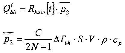
- the change in the amount of heat from the induction heating device 6 to the node i is calculated by the following equation, for example.
- the penetration depth coefficient represents the penetration depth of the current.
- the penetration depth coefficient can be obtained using, for example, a cubic function represented by the following equation.
- the set power calculation device 7 compares the volume average temperature of the steel material 1 obtained in S10 with the temperature pattern set value generated in S7, and obtains the deviation. The set power calculation device 7 determines whether or not the obtained deviation is within a specified range. When the obtained deviation is out of the specified range (No in S11), the set power calculation device 7 corrects the set value of power for the induction heating device 6 (S12).
- the set power calculation device 7 determines whether or not the power of the induction heating device 6 corrected in S12 is within the limit range (S13). If the power of the induction heating device 6 is within the limit range (Yes in S13), the set power calculation device 7 performs the calculations of S8 to S10 again based on the power of the induction heating device 6 reset in S12. The set power calculation device 7 repeats the processes shown in S8 to S13 until the deviation between the volume average temperature of the steel material 1 obtained in S10 and the temperature pattern set value generated in S7 falls within a specified range.
- the set power calculation device 7 performs the processing shown in S8 to S13 on the entire length of the steel material 1. For example, the set power calculation device 7 performs the processes shown in S8 to S13 on the segment j (j is a segment number). When the deviation falls within the specified range in S11, the set power calculation device 7 ends the process for the segment j and sets the power at that time to the power for the segment j. Moreover, also when the electric power of the induction heating apparatus 6 deviates from a limit range in S13, the process with respect to the segment j is complete
- the electric power pattern of the induction heating apparatus 6 required in order to achieve a desired temperature rising pattern setting can be calculated
- the set power calculation device 7 calculates the volume average temperature over the entire length of the steel material 1 using a speed pattern set in advance as the conveyance speed of the steel material 1 before the steel material 1 is rolled by the finish rolling mill 5. . Moreover, after the rolling by the finish rolling mill 5 is started, the set power calculation device 7 calculates the volume average temperature over the entire length of the steel material 1 using the speed detected by the speed detector 4 as the conveying speed of the steel material 1. calculate. Alternatively, the set power calculation device 7 may use both the speed detected by the speed detector 4 as the conveyance speed of the steel material 1 and a preset speed pattern. You may change both said ratios with progress of time, and the obtained value may be used as a conveyance speed of steel materials 1.
- the set power calculation device 7 includes, as hardware resources, for example, a circuit including an input / output interface, a CPU, and a memory.
- the set power calculation device 7 implements each process (function) shown in FIG. 2 by executing a program stored in the memory by the CPU. You may implement
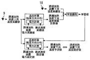
- FIG. FIG. 7 is a diagram showing a configuration of a main part of the rolling system according to Embodiment 2 of the present invention. In the present embodiment, a case where the set power calculation device 7 has a learning function will be described.
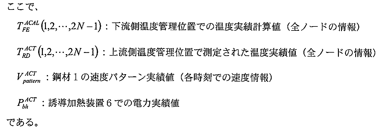
- a series of temperature calculations as described in the first embodiment when the steel material 1 moves from the upstream temperature management position to the downstream temperature management position is expressed as follows.
- the following equation shows the temperature calculation when heating by the induction heating device 6 is performed.
- temp_cal ⁇ is a series of calculation formulas obtained by applying the finite difference method to the unsteady heat conduction equation shown in Embodiment 1 and discretizing the space in the cross section of the steel material 1 and the transport time on the transport line. Represents.
- the actual temperature value at the upstream temperature management position (information on all nodes), the speed pattern of the steel material 1 (speed information at each time), and the power setting value in the induction heating device 6 are input.
- the temperature (information of all nodes) of the steel material 1 at the downstream temperature management position is calculated. This temperature is referred to herein as a “temperature calculation value”.
- the actual temperature value at the upstream temperature management position (information of all nodes), the actual speed pattern value of the steel material 1 (speed information at each time), and the induction heating device are also calculated by the same calculation method after rolling the steel material 1.
- the temperature of the steel material 1 at the downstream temperature management position (information on all nodes) can be calculated using the actual power value at 6 as input information. This temperature is referred to herein as “temperature actual calculation value”.
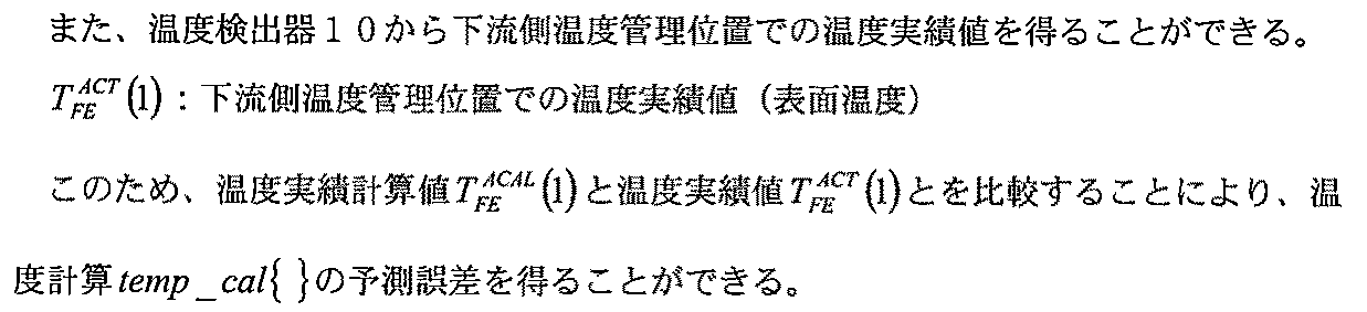
- a learning term obtained by subjecting the obtained prediction error to smoothing processing is defined as Z fet and added to the final result of the temperature calculation temp_cal ⁇ . That is, the new temperature calculation is expressed by the following equation.
- the learning term Z fet is recorded in association with the type of the steel material 1.
- the recorded learning term Z fet may be read and used next time when rolling the same type of steel material . Note that the method of using the learning term Z fet is not limited to this.
- the set power calculation device 7 first determines the surface temperature of the steel material 1 at the downstream temperature management position based on the temperature of the steel material 1 detected by the temperature detector 9 and the power actually supplied to the induction heating device 6. Calculate And based on the calculated surface temperature and the temperature of the steel material 1 detected by the temperature detector 10, the parameter used when calculating volume average temperature is corrected. Thereby, when performing the next heat processing, a power pattern can be calculated
- the present invention can be applied to a rolling system equipped with an induction heating device.
Landscapes
- Engineering & Computer Science (AREA)
- Mechanical Engineering (AREA)
- Chemical & Material Sciences (AREA)
- Physics & Mathematics (AREA)
- Thermal Sciences (AREA)
- Crystallography & Structural Chemistry (AREA)
- Materials Engineering (AREA)
- Metallurgy (AREA)
- Organic Chemistry (AREA)
- General Induction Heating (AREA)
- Control Of Metal Rolling (AREA)
- Control Of Heat Treatment Processes (AREA)
Abstract
Description
図1は、この発明の実施の形態1における圧延システムを示す構成図である。圧延ラインの一例として、熱間圧延ラインを示している。

Tva:体積平均温度
T[i]:ノードiの温度
Vi:ノードiの体積
i:ノード番号(1、2、・・・、2N-1)
である。



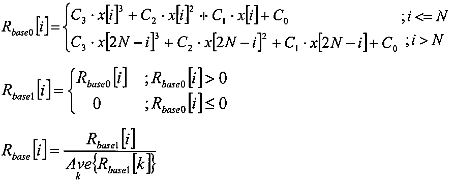
i:ノード番号(1、2、・・・、2N-1)
Ck:パラメータ
x[i]:ノードiの表面からの深さ
である。
図7は、この発明の実施の形態2における圧延システムの要部の構成を示す図である。本実施の形態では、設定電力計算装置7が学習機能を有する場合について説明する。





2 搬送テーブル
3 テーブルロール
4 速度検出器
5 仕上げ圧延機
6 誘導加熱装置
7 設定電力計算装置
8 電力制御装置
9、10、11 温度検出器
12 昇温パターン設定決定装置
Claims (7)
- 搬送テーブルによって搬送される材料を加熱する誘導加熱装置と、
前記誘導加熱装置より上流の第1位置で材料の温度を検出する第1温度検出器と、
前記誘導加熱装置より下流に設けられ、材料を圧延する仕上げ圧延機と、
前記誘導加熱装置より下流且つ前記仕上げ圧延機より上流の第2位置で材料の温度を検出する第2温度検出器と、
前記誘導加熱装置に必要な電力を計算する設定電力計算装置と、
を備え、
前記設定電力計算装置は、
前記第1温度検出器によって検出された温度に基づいて、前記第1位置における材料の板厚方向の温度分布パターンを生成する生成手段と、
前記生成手段によって生成された温度分布パターンに基づいて、材料が前記第1位置から前記第2位置に移動した時の前記第2位置における材料の体積平均温度を計算する第1計算手段と、
前記第1計算手段によって計算された体積平均温度が前記第2位置における材料の目標温度に追従するように、前記誘導加熱装置に必要な電力を計算する第2計算手段と、
を備え、
前記第1計算手段は、材料を板厚方向にノード分割し、放射冷却、空気対流による抜熱、前記搬送テーブルのテーブルロールへの抜熱、隣接するノード間の温度差から生じる熱伝導及び前記誘導加熱装置からの熱量変化に基づいて各ノードの温度変化を算出し、その算出結果に基づいて材料の体積平均温度を計算する圧延システム。 - 前記搬送テーブルによって搬送される材料の速度を検出する速度検出器と、
を更に備え、
前記第1計算手段は、
材料が前記仕上げ圧延機によって圧延される前は、材料の搬送速度として予め設定された予測速度パターンを用いて材料の全長に渡る体積平均温度を計算し、
前記仕上げ圧延機による圧延が開始された後は、材料の搬送速度として前記速度検出器によって検出された速度を用いて又は前記速度検出器によって検出された速度と前記予測速度パターンとの双方を用いて、材料の全長に渡る体積平均温度を計算する
請求項1に記載の圧延システム。 - 昇温パターン設定を決定するための昇温パターン設定決定装置と、
を更に備え、
前記第2計算手段は、前記昇温パターン設定決定装置によって決定された昇温パターン設定と前記誘導加熱装置による加熱が行われない時の前記第2位置における材料の体積平均温度とに基づいて、前記第2位置における材料の目標温度を設定する請求項1又は請求項2に記載の圧延システム。 - 前記第2計算手段は、前記生成手段によって生成された温度分布パターンに基づいて、前記誘導加熱装置による加熱が行われない時の前記第2位置における材料の体積平均温度を計算する請求項3に記載の圧延システム。
- 前記第2位置は、前記仕上げ圧延機の入側に近接する位置であり、
前記第1計算手段は、材料を長手方向に一定長のセグメントに分割した時の各セグメントに対して体積平均温度を計算し、
前記第2計算手段は、材料の各セグメントに対して目標温度を設定する
請求項3又は請求項4に記載の圧延システム。 - 前記第2計算手段は、前記第1計算手段によって計算された体積平均温度と前記第2位置における材料の目標温度との差が基準の範囲から外れる場合は、前記第1計算手段に、体積平均温度を計算する際に使用した電力の値を再設定して体積平均温度を再計算させる請求項1から請求項5の何れか一項に記載の圧延システム。
- 前記搬送テーブルによって搬送される材料の速度を検出する速度検出器と、
を更に備え、
前記第1計算手段は、前記第1温度検出器によって検出された温度と前記速度検出器によって検出された速度と前記誘導加熱装置に実際に供給された電力とに基づいて前記第2位置における材料の表面温度を計算し、計算された表面温度と前記第2温度検出器によって検出された温度とに基づいて、体積平均温度を計算する際に使用するパラメータを修正する請求項1に記載の圧延システム。
Priority Applications (5)
| Application Number | Priority Date | Filing Date | Title |
|---|---|---|---|
| JP2016514616A JP6241545B2 (ja) | 2014-04-23 | 2014-04-23 | 圧延システム |
| US15/302,297 US10500619B2 (en) | 2014-04-23 | 2014-04-23 | Rolling system |
| CN201480078199.8A CN106232250B (zh) | 2014-04-23 | 2014-04-23 | 轧制系统 |
| KR1020167032069A KR101821089B1 (ko) | 2014-04-23 | 2014-04-23 | 압연 시스템 |
| PCT/JP2014/061448 WO2015162728A1 (ja) | 2014-04-23 | 2014-04-23 | 圧延システム |
Applications Claiming Priority (1)
| Application Number | Priority Date | Filing Date | Title |
|---|---|---|---|
| PCT/JP2014/061448 WO2015162728A1 (ja) | 2014-04-23 | 2014-04-23 | 圧延システム |
Publications (1)
| Publication Number | Publication Date |
|---|---|
| WO2015162728A1 true WO2015162728A1 (ja) | 2015-10-29 |
Family
ID=54331917
Family Applications (1)
| Application Number | Title | Priority Date | Filing Date |
|---|---|---|---|
| PCT/JP2014/061448 Ceased WO2015162728A1 (ja) | 2014-04-23 | 2014-04-23 | 圧延システム |
Country Status (5)
| Country | Link |
|---|---|
| US (1) | US10500619B2 (ja) |
| JP (1) | JP6241545B2 (ja) |
| KR (1) | KR101821089B1 (ja) |
| CN (1) | CN106232250B (ja) |
| WO (1) | WO2015162728A1 (ja) |
Families Citing this family (7)
| Publication number | Priority date | Publication date | Assignee | Title |
|---|---|---|---|---|
| CN109092910B (zh) * | 2018-07-24 | 2019-12-24 | 山东钢铁股份有限公司 | 一种电磁感应线圈补偿加热设备及其提高轧材质量的方法 |
| JP7095651B2 (ja) * | 2019-05-14 | 2022-07-05 | 東芝三菱電機産業システム株式会社 | エッジヒータの制御システム |
| KR102297062B1 (ko) * | 2019-06-14 | 2021-09-03 | 도시바 미쓰비시덴키 산교시스템 가부시키가이샤 | 판 두께 제어 장치 및 판 두께 제어 방법 |
| CN112684831A (zh) * | 2020-12-04 | 2021-04-20 | 辽沈工业集团有限公司 | 一种覆铜钢板迭热轧加热温度控制系统 |
| CN113275388A (zh) * | 2021-05-17 | 2021-08-20 | 日照钢铁控股集团有限公司 | 一种热轧薄带钢生产的控温系统及方法 |
| CN116426744B (zh) * | 2023-04-12 | 2025-09-09 | 广东朗盾科技有限公司 | 一种均质炉温度控制方法、系统及存储介质 |
| CN119500788B (zh) * | 2024-10-29 | 2025-08-05 | 宿迁南钢金鑫轧钢有限公司 | 一种小型钢连轧工艺的生产控制方法及系统 |
Citations (5)
| Publication number | Priority date | Publication date | Assignee | Title |
|---|---|---|---|---|
| JPS62185829A (ja) * | 1986-02-12 | 1987-08-14 | Kawasaki Steel Corp | 圧延温度制御装置 |
| JPH10128423A (ja) * | 1996-10-30 | 1998-05-19 | Nkk Corp | 表面性状に優れた熱延鋼帯を製造する熱間圧延設備列および圧延方法 |
| JP2003275804A (ja) * | 2002-03-22 | 2003-09-30 | Jfe Steel Kk | 熱延鋼帯の製造方法 |
| JP2005068553A (ja) * | 2003-08-06 | 2005-03-17 | Jfe Steel Kk | 熱処理装置及び鋼材の製造方法 |
| JP2010247234A (ja) * | 2010-05-14 | 2010-11-04 | Nippon Steel Corp | 冷却制御方法、装置、及びコンピュータプログラム |
Family Cites Families (7)
| Publication number | Priority date | Publication date | Assignee | Title |
|---|---|---|---|---|
| US5990464A (en) * | 1996-10-30 | 1999-11-23 | Nkk Corporation | Method for producing hot rolled steel sheet using induction heating and apparatus therefor |
| RU2134179C1 (ru) * | 1998-06-10 | 1999-08-10 | Открытое акционерное общество Акционерная холдинговая компания "Всероссийский научно-исследовательский и проектно-конструкторский институт металлургического машиностроения имени академика Целикова" | Способ получения мелкосортового проката в совмещенном литейно-прокатном агрегате и устройство для его осуществления |
| JP4631247B2 (ja) | 2002-02-07 | 2011-02-16 | Jfeスチール株式会社 | 鋼材の熱処理方法及びそのプログラム |
| EP1496129A4 (en) * | 2002-04-08 | 2006-02-22 | Jfe Steel Corp | THERMAL PROCESSING DEVICE AND METHOD, SUPPORT FOR RECORDING THERMAL PROCESSING PROGRAM, AND STEEL PRODUCT |
| AU2003238695A1 (en) * | 2002-06-07 | 2004-01-06 | Nippon Steel Corporation | Hot rolling method and apparatus for hot steel sheet |
| JP5466905B2 (ja) * | 2009-09-16 | 2014-04-09 | 東芝三菱電機産業システム株式会社 | 誘導加熱装置及び誘導加熱装置の制御方法 |
| JP5655852B2 (ja) * | 2010-03-11 | 2015-01-21 | 新日鐵住金株式会社 | 熱延鋼板の製造方法及び製造装置 |
-
2014
- 2014-04-23 KR KR1020167032069A patent/KR101821089B1/ko active Active
- 2014-04-23 JP JP2016514616A patent/JP6241545B2/ja active Active
- 2014-04-23 WO PCT/JP2014/061448 patent/WO2015162728A1/ja not_active Ceased
- 2014-04-23 US US15/302,297 patent/US10500619B2/en active Active
- 2014-04-23 CN CN201480078199.8A patent/CN106232250B/zh active Active
Patent Citations (5)
| Publication number | Priority date | Publication date | Assignee | Title |
|---|---|---|---|---|
| JPS62185829A (ja) * | 1986-02-12 | 1987-08-14 | Kawasaki Steel Corp | 圧延温度制御装置 |
| JPH10128423A (ja) * | 1996-10-30 | 1998-05-19 | Nkk Corp | 表面性状に優れた熱延鋼帯を製造する熱間圧延設備列および圧延方法 |
| JP2003275804A (ja) * | 2002-03-22 | 2003-09-30 | Jfe Steel Kk | 熱延鋼帯の製造方法 |
| JP2005068553A (ja) * | 2003-08-06 | 2005-03-17 | Jfe Steel Kk | 熱処理装置及び鋼材の製造方法 |
| JP2010247234A (ja) * | 2010-05-14 | 2010-11-04 | Nippon Steel Corp | 冷却制御方法、装置、及びコンピュータプログラム |
Also Published As
| Publication number | Publication date |
|---|---|
| CN106232250A (zh) | 2016-12-14 |
| US20170028452A1 (en) | 2017-02-02 |
| KR20160146856A (ko) | 2016-12-21 |
| JP6241545B2 (ja) | 2017-12-06 |
| JPWO2015162728A1 (ja) | 2017-04-13 |
| KR101821089B1 (ko) | 2018-01-22 |
| CN106232250B (zh) | 2018-07-20 |
| US10500619B2 (en) | 2019-12-10 |
Similar Documents
| Publication | Publication Date | Title |
|---|---|---|
| JP6241545B2 (ja) | 圧延システム | |
| US4307276A (en) | Induction heating method for metal products | |
| TWI224144B (en) | Heat treating device, heat treating method, recording medium recording heat treating program and steel product | |
| CN103108706B (zh) | 用于在精轧机列中的金属热轧带材的温度和几何形状的实时测定方法 | |
| JP5391205B2 (ja) | 制御装置 | |
| JP6146553B1 (ja) | 鋼板の温度制御装置及び温度制御方法 | |
| KR102122143B1 (ko) | 강판의 온도 제어 장치 및 온도 제어 방법 | |
| JP6642289B2 (ja) | 圧延ラインの数学モデル算出装置および圧延材の温度制御装置 | |
| JP2015040333A (ja) | 鋼材の温度予測方法及び炉温制御方法、ならびに、鋼材の温度予測装置及び炉温制御装置 | |
| JPWO2017046846A1 (ja) | 圧延材の温度制御装置 | |
| JP6428932B2 (ja) | 先尾端板幅制御装置 | |
| CN113133310A (zh) | 串联轧机的板厚一览表计算方法及轧制设备 | |
| JP4349177B2 (ja) | 連続式加熱炉の鋼材抽出温度予測方法 | |
| JP2018123364A (ja) | 鋼板の温度制御方法、及び、鋼板の温度制御装置 | |
| JP2011173153A (ja) | 厚鋼板の冷却制御装置、冷却制御方法、及び、製造方法 | |
| JP6627609B2 (ja) | 冷却制御方法及び冷却装置 | |
| CN109070161B (zh) | 修边机的控制装置 | |
| JP6075309B2 (ja) | 加熱炉の制御方法及び制御装置 | |
| JP6822390B2 (ja) | 厚鋼板の粗圧延時間算出方法、厚鋼板の粗圧延時間算出装置、及び厚鋼板の製造方法 | |
| JP5581600B2 (ja) | 加熱炉抽出間隔決定方法 | |
| JP4306179B2 (ja) | 鋼材の熱処理方法及びそのプログラム | |
| JP2000208241A (ja) | 誘導加熱装置の加熱制御方法 | |
| JP2017164758A (ja) | 圧延ラインのミルペーシング制御方法 | |
| KR101626604B1 (ko) | 판재의 온도 예측 장치 및 방법 | |
| JP2014196534A (ja) | 鋼板の熱処理温度管理方法 |
Legal Events
| Date | Code | Title | Description |
|---|---|---|---|
| 121 | Ep: the epo has been informed by wipo that ep was designated in this application |
Ref document number: 14890044 Country of ref document: EP Kind code of ref document: A1 |
|
| ENP | Entry into the national phase |
Ref document number: 2016514616 Country of ref document: JP Kind code of ref document: A |
|
| WWE | Wipo information: entry into national phase |
Ref document number: 15302297 Country of ref document: US |
|
| NENP | Non-entry into the national phase |
Ref country code: DE |
|
| ENP | Entry into the national phase |
Ref document number: 20167032069 Country of ref document: KR Kind code of ref document: A |
|
| 122 | Ep: pct application non-entry in european phase |
Ref document number: 14890044 Country of ref document: EP Kind code of ref document: A1 |