WO2015159909A1 - 車両用表示装置 - Google Patents
車両用表示装置 Download PDFInfo
- Publication number
- WO2015159909A1 WO2015159909A1 PCT/JP2015/061546 JP2015061546W WO2015159909A1 WO 2015159909 A1 WO2015159909 A1 WO 2015159909A1 JP 2015061546 W JP2015061546 W JP 2015061546W WO 2015159909 A1 WO2015159909 A1 WO 2015159909A1
- Authority
- WO
- WIPO (PCT)
- Prior art keywords
- image
- vehicle
- virtual viewpoint
- display device
- screen
- Prior art date
- Legal status (The legal status is an assumption and is not a legal conclusion. Google has not performed a legal analysis and makes no representation as to the accuracy of the status listed.)
- Ceased
Links
Images

Classifications
-
- G—PHYSICS
- G08—SIGNALLING
- G08G—TRAFFIC CONTROL SYSTEMS
- G08G1/00—Traffic control systems for road vehicles
- G08G1/16—Anti-collision systems
- G08G1/166—Anti-collision systems for active traffic, e.g. moving vehicles, pedestrians, bikes
Definitions
- the present invention relates to a vehicle display device that displays an image representing a preceding vehicle and an image representing the host vehicle.
- a follow-up traveling system that controls the vehicle speed so as to follow a preceding vehicle while maintaining a safe inter-vehicle distance has been proposed, and is disclosed in, for example, Patent Document 1.
- Such a follow-up traveling system is provided with a laser radar at the front of the vehicle, detects the distance from the own vehicle to the preceding vehicle by the laser radar, and makes the distance between the own vehicle and the preceding vehicle appropriate. The speed is controlled.
- the host vehicle travels at a speed set in advance by the driver, but travels to follow the preceding vehicle when it catches up with the preceding vehicle.
- a follow-up traveling system is configured such that the distance between the host vehicle and the preceding vehicle can be set by an operating means such as a push button switch in accordance with the preference of the vehicle driver.
- the inter-vehicle distance set by the vehicle driver is displayed on the vehicle display device.
- an obstacle notification system that notifies that an obstacle (another vehicle or the like) exists on the left rear or right rear of the host vehicle has been proposed, and is disclosed in, for example, Patent Document 2.
- Such an obstacle notification system for example, notifies that another vehicle is approaching from the left rear or right rear of the host vehicle when changing lanes.
- the host vehicle display unit that represents the host vehicle and the preceding vehicle display unit that represents the preceding vehicle are display units that simulate the side surface of the vehicle.
- the present invention has been made in view of this problem, and provides a display device for a vehicle that can display operating states of a plurality of driving support systems.
- the present invention is a vehicle display device comprising: a display; and a control unit that displays a first image representing a preceding vehicle and a second image representing the host vehicle on a screen of the display.
- the first image is an image as if the preceding vehicle was viewed from a first virtual viewpoint
- the second image is the vehicle from a second virtual viewpoint that is higher than the first virtual viewpoint. It is an image as seen.
- this invention is a display apparatus for vehicles provided with the display and the control means on which the 1st image showing a preceding vehicle and the 2nd image showing the own vehicle are displayed on the screen of the said display.
- the first image is an image as if the preceding vehicle was viewed from the first virtual viewpoint at the first depression angle
- the second image was viewed from the second virtual viewpoint from the first depression angle. Is an image as if the host vehicle was seen at a large second depression angle.
- control means displays a third image indicating whether or not an obstacle exists around the host vehicle on the screen.
- control means displays a fourth image representing an operating state of the following traveling system on the screen.
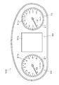
- the vehicle display device 100 includes a speedometer 10, a tachometer 20, and a liquid crystal display 30.
- the speedometer 10 is a pointer-type meter having a dial 11 and a pointer 12, and displays the speed of the vehicle.
- the pointer 12 is rotated by the stepping motor 13 to indicate the indicator portion 11a of the dial plate 11.
- the tachometer 20 is a pointer-type instrument having a dial 21 and a pointer 22, and displays the engine speed.
- the pointer 22 is rotated by the stepping motor 23 to indicate the indicator portion 21a of the dial 22.
- the liquid crystal display 30 is composed of a TFT liquid crystal display module, and is disposed between the speedometer 10 and the tachometer 20.
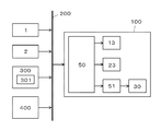
- FIG. 2 is a block diagram showing the electrical configuration of the present embodiment.
- Reference numeral 1 denotes a speed sensor, which detects the speed of the vehicle and outputs speed data.
- the vehicle display device 100 inputs speed data output from the speed sensor 1 via a CAN (Controller (Area Network) 200.
- Reference numeral 2 denotes a rotation sensor.
- the rotation sensor 2 detects the rotation speed of the engine and outputs rotation speed data.
- the vehicle display device 100 receives the rotation speed data output from the rotation sensor 2 via the CAN 200.
- Reference numeral 50 denotes a microcomputer (control means).
- the microcomputer 50 drives the stepping motors 13 and 23 and displays various images on the screen 30 a of the liquid crystal display 30 via the graphic controller 51.
- the 300 is a follow-up running system (running support system), and this follow-up running system 300 controls the speed of the vehicle while capturing the preceding vehicle with a laser radar so that the host vehicle follows the preceding vehicle.
- the following traveling system 300 includes an inter-vehicle distance setting unit 301, and the vehicle driver sets an inter-vehicle distance in the inter-vehicle distance setting unit 301.
- Reference numeral 400 denotes an obstacle notification system (running support system). The obstacle notification system 400 notifies the presence of a vehicle at the left rear or right rear of the host vehicle.
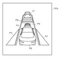
- FIG. 3 shows a screen 30 a of the liquid crystal display 30.
- the image P1 (first image) represents the preceding vehicle.
- the image P2 (second image) represents the host vehicle, and the image P2 representing the host vehicle is displayed below the screen 30a than the image P1 representing the preceding vehicle.
- the image P3 (third image) notifies that there is another vehicle on the left rear side of the host vehicle, and the image P3 is displayed on the left side of the image P2 representing the host vehicle.
- the image P4 (third image) notifies that there is another vehicle on the right rear side of the host vehicle, and the image P4 is displayed on the right side of the image P2 representing the host vehicle.
- the image P5 (fourth image) is composed of a plurality of bar display units and represents the inter-vehicle distance set by the inter-vehicle distance setting unit 301 of the follow-up traveling system 300.
- the image P6 (fourth image) is composed of a plurality of arc-shaped display units that imitate laser radar, and indicates that the laser radar is operating.
- the image P7 is composed of two linear display portions and represents a vehicle lane.
- the image P1 representing the preceding vehicle is an image as if the preceding vehicle was seen from the virtual viewpoint V1 at the height H1 from the virtual road surface R.
- the virtual viewpoint V1 is directly behind the preceding vehicle, and the image P1 representing the preceding vehicle is an image imitating the rear surface of the vehicle.
- the image P2 representing the host vehicle is an image as seen from the virtual viewpoint V2 at the height H2 from the virtual road surface R.
- the virtual viewpoint V2 is at a higher position than the virtual viewpoint V1.
- the virtual viewpoint V2 is behind the host vehicle, and the image P2 representing the host vehicle is an image as if the vehicle is looked down slightly.
- the preceding vehicle and the own vehicle are viewed from one virtual viewpoint. Make an image like this.
- the rear surface of the preceding vehicle is captured by a laser radar. Therefore, in order to display the operation status of the following traveling system 300, an image representing the preceding vehicle is obtained by looking at the preceding vehicle from directly behind.
- images P3 and P4 that notify that another vehicle exists are displayed beside the image P2 that represents the host vehicle. Since it is desirable to have an image as if the host vehicle was looked down from directly above, it was difficult to display the operating status of the following traveling system 300 and the operating status of the obstacle notification system 400 on one screen.
- the image P1 representing the preceding vehicle is changed to an image as if the preceding vehicle was seen from the virtual viewpoint V1 at the height H1 from the virtual road surface R, and the image P2 representing the host vehicle is changed from the virtual road surface R.
- the operating status of the following traveling system 300 and the operating status of the obstacle notification system 400 are displayed on one screen 30a. Can do.
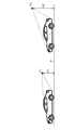
- the image P1 representing the preceding vehicle is changed to an image as if the preceding vehicle was viewed at the depression angle ⁇ 1 from the virtual viewpoint V3 at the infinity point, and the image representing the host vehicle was used.
- P2 may be an image as if the host vehicle was viewed from the virtual viewpoint V4 at the infinity point at a depression angle ⁇ 2 larger than the depression angle ⁇ 1.
- the depression angle ⁇ 1 may be 0 degrees.
- the present invention is suitable for a vehicle display device mounted on a vehicle provided with a follow-up traveling system that controls the vehicle speed so as to follow the preceding vehicle.
Landscapes
- Physics & Mathematics (AREA)
- General Physics & Mathematics (AREA)
- Instrument Panels (AREA)
- Traffic Control Systems (AREA)
- Control Of Driving Devices And Active Controlling Of Vehicle (AREA)
Abstract
複数の走行支援システムの作動状況を表示可能な車両用表示装置を提供する。 制御手段50は、先行車両を表す第一の画像P1及び自車両を表す第二の画像P2を表示器30の画面30aに表示させる。第一の画像P1は、第一の仮想視点V1から先行車両を見たような画像である。第二の画像P2は、第一の仮想視点V1よりも高い第二の仮想視点V2から自車両を見たような画像である。制御手段50は、自車両の周辺に障害物が存在するか否かを表す第三の画像P3,P4を画面30aに表示させる。制御手段30は、追従走行システムの作動状況を表す第四の画像P5,P6を画面30aに表示させる。
Description
本発明は、先行車両を表す画像及び自車両を表す画像を表示する車両用表示装置に関するものである。
従来より、安全な車間距離を保ちながら先行車両に追従するように車速を制御する追従走行システムが提案されており、例えば特許文献1に開示されている。斯かる追従走行システムは、車両の前部にレーザレーダを設け、このレーザレーダにより自車両から先行車両までの距離を検出し、自車両と先行車両の車間距離が適切になるように、自車両の速度を制御するものである。
自車両は、運転者が予め設定した速度で走行するが、先行車両に追いついたときには、先行車両に追従するように走行する。このような追従走行システムでは、車両運転者の好みに応じて自車両と先行車両の車間距離を、押釦スイッチ等の操作手段で設定できるように構成されている。車両運転者により設定された車間距離は、車両用表示装置に表示される。
一方、自車両の左後方または右後方に、障害物(他の車両等)が存在することを報知する障害物報知システムが提案されており、例えば特許文献2に開示されている。斯かる障害物報知システムは、例えば車線変更する際に、自車両の左後方または右後方から他の車両が接近していることを報知するものである。
しかしながら、特許文献1に開示された車両用表示装置は、自車両を表す自車両表示部と、先行車両を表す先行車両表示部とが、車両の側面を模した表示部であるため、自車両表示部の近傍に、障害物報知システムの作動状況を表示することができないという問題を有していた。
本発明は、この問題に鑑みなされたものであり、複数の走行支援システムの作動状況を表示可能な車両用表示装置を提供するものである。
本発明は、この問題に鑑みなされたものであり、複数の走行支援システムの作動状況を表示可能な車両用表示装置を提供するものである。
本発明は、表示器と、先行車両を表す第一の画像及び自車両を表す第二の画像を前記表示器の画面に表示させる制御手段と、を備えた車両用表示装置であって、前記第一の画像は、第一の仮想視点から前記先行車両を見たような画像であり、前記第二の画像は、前記第一の仮想視点よりも高い第二の仮想視点から前記自車両を見たような画像であるものである。
また、本発明は、表示器と、先行車両を表す第一の画像及び自車両を表す第二の画像を前記表示器の画面に表示させる制御手段と、を備えた車両用表示装置であって、前記第一の画像は、第一の仮想視点から第一の俯角で前記先行車両を見たような画像であり、前記第二の画像は、第二の仮想視点から前記第一の俯角よりも大きい第二の俯角で前記自車両を見たような画像であるものである。
また、本発明は、前記制御手段は、前記自車両の周辺に障害物が存在するか否かを表す第三の画像を前記画面に表示させるものである。
また、本発明は、前記制御手段は、追従走行システムの作動状況を表す第四の画像を前記画面に表示させるものである。
1個の画面に複数の走行支援システムの作動状況を表示することが可能になる。
以下、添付図面に基づいて、本発明の一実施形態を説明する。車両用表示装置100は、速度計10,回転計20,液晶表示器30を備えている。
速度計10は、文字板11及び指針12を有する指針式計器であり、車両の速度を表示する。指針12は、ステッピングモータ13によって回動され、文字板11の指標部11aを指示する。回転計20は、文字板21及び指針22を有する指針式計器であり、エンジンの回転数を表示する。指針22は、ステッピングモータ23によって回動され、文字板22の指標部21aを指示する。液晶表示器30は、TFT型液晶表示モジュールからなるものであり、速度計10と回転計20の間に配置されている。
図2は、本実施形態の電気的構成を示すブロック図である。1は速度センサであり、この速度センサは、車両の速度を検出し、速度データを出力する。車両用表示装置100は、CAN(Controller Area Network)200を介して、速度センサ1が出力した速度データを入力する。2は回転センサであり、この回転センサ2は、エンジンの回転数を検出し、回転数データを出力する。車両用表示装置100は、CAN200を介して、回転センサ2が出力した回転数データを入力する。50はマイコン(制御手段)であり、このマイコン50は、ステッピングモータ13,23を駆動すると共に、グラフィックコントローラ51を介して、液晶表示器30の画面30aに種々の画像を表示させる。
300は追従走行システム(走行支援システム)であり、この追従走行システム300は、自車両が先行車両に追従して走行するように、レーザレーダで先行車両を捉えながら、車両の速度を制御する。追従走行システム300は車間距離設定部301を有しており、この車間距離設定部301にて車両運転者が車間距離を設定する。400は障害物報知システム(走行支援システム)であり、この障害物報知システム400は、自車両の左後方または右後方にある車両の存在を報知するものである。
図3は液晶表示器30の画面30aを示すものである。画像P1(第一の画像)は先行車両を表すものである。画像P2(第二の画像)は自車両を表すものであり、この自車両を表す画像P2は、先行車両を表す画像P1よりも、画面30aの下側に表示される。画像P3(第三の画像)は自車両の左後方に他の車両が存在することを報知するものであり、この画像P3は自車両を表す画像P2の左側に表示される。画像P4(第三の画像)は自車両の右後方に他の車両が存在することを報知するものであり、この画像P4は自車両を表す画像P2の右側に表示される。
画像P5(第四の画像)は、複数のバー表示部からなるものであり、追従走行システム300の車間距離設定部301によって設定された車間距離を表している。画像P6(第四の画像)は、レーザレーダを模した複数の円弧状の表示部からなるものであり、レーザレーダが作動していることを表している。画像P7は、2本の直線状の表示部からなるものであり、車両通行帯を表している。
先行車両を表す画像P1は、仮想路面Rから高さH1にある仮想視点V1から先行車両を見たような画像である。仮想視点V1は先行車両の真後ろにあり、先行車両を表す画像P1は、車両の後面を模した画像になっている。自車両を表す画像P2は、仮想路面Rから高さH2にある仮想視点V2から自車両を見たような画像である。仮想視点V2は、仮想視点V1よりも高い位置にある。仮想視点V2は、自車両よりも後方にあり、自車両を表す画像P2は、車両を若干見下ろしたような画像になっている。
液晶表示器30の画面30aに、先行車両を模した画像及び自車両を模した画像を同時に表示する場合、一般的な描画手法としては、先行車両及び自車両を1個の仮想視点から見たような画像にする。しかしながら、追従走行システム300では、先行車両の後面をレーザレーダで捉えているため、追従走行システム300の作動状況を表示するには、先行車両を表す画像が、先行車両を真後ろから見たような画像にすることが望ましい一方、障害物報知システム400では、自車両を表す画像P2の横に、他の車両が存在することを報知する画像P3,P4を表示させるため、自車両を表す画像が、自車両を真上から見下ろしたような画像であることが望ましいので、追従走行システム300の作動状況と、障害物報知システム400の作動状況とを1画面に表示することは困難であった。
本実施形態では、先行車両を表す画像P1を、仮想路面Rから高さH1にある仮想視点V1から先行車両を見たような画像にすると共に、自車両を表す画像P2を、仮想路面Rから高さH2にある仮想視点V2から自車両を見たような画像とすることによって、追従走行システム300の作動状況と、障害物報知システム400の作動状況とを1個の画面30aに表示することができる。
なお、図5に示す他の実施形態の如く、先行車両を表す画像P1を、無限遠点にある仮想視点V3から俯角α1で先行車両を見たような画像にすると共に、自車両を表す画像P2を、無限遠点にある仮想視点V4から、俯角α1よりも大きい俯角α2で自車両を見たような画像としても良い。なお、俯角α1は、0度であっても良い。
本発明は、先行車両に追従するように車速を制御する追従走行システムを備えた車両に搭載される車両用表示装置に好適である。
30 表示器
30a 画面
50 マイコン(制御手段)
300 追従走行システム
400 障害物報知システム
P1 第一の画像
P2 第二の画像
P3 第三の画像
P4 第三の画像
P5 第四の画像
P6 第四の画像
V1 仮想視点(第一の仮想視点)
V2 仮想視点(第二の仮想視点)
V3 仮想視点(第一の仮想視点)
V4 仮想視点(第二の仮想視点)
α1 俯角(第一の俯角)
α2 俯角(第二の俯角)
30a 画面
50 マイコン(制御手段)
300 追従走行システム
400 障害物報知システム
P1 第一の画像
P2 第二の画像
P3 第三の画像
P4 第三の画像
P5 第四の画像
P6 第四の画像
V1 仮想視点(第一の仮想視点)
V2 仮想視点(第二の仮想視点)
V3 仮想視点(第一の仮想視点)
V4 仮想視点(第二の仮想視点)
α1 俯角(第一の俯角)
α2 俯角(第二の俯角)
Claims (4)
- 表示器と、先行車両を表す第一の画像及び自車両を表す第二の画像を前記表示器の画面に表示させる制御手段と、を備えた車両用表示装置であって、
前記第一の画像は、第一の仮想視点から前記先行車両を見たような画像であり、前記第二の画像は、前記第一の仮想視点よりも高い第二の仮想視点から前記自車両を見たような画像であることを特徴とする車両用表示装置。 - 表示器と、先行車両を表す第一の画像及び自車両を表す第二の画像を前記表示器の画面に表示させる制御手段と、を備えた車両用表示装置であって、
前記第一の画像は、第一の仮想視点から第一の俯角で前記先行車両を見たような画像であり、前記第二の画像は、第二の仮想視点から前記第一の俯角よりも大きい第二の俯角で前記自車両を見たような画像であることを特徴とする車両用表示装置。 - 前記制御手段は、前記自車両の周辺に障害物が存在するか否かを表す第三の画像を前記画面に表示させることを特徴とする請求項1または請求項2に記載の車両用表示装置。
- 前記制御手段は、追従走行システムの作動状況を表す第四の画像を前記画面に表示させることを特徴とする請求項1または請求項2に記載の車両用表示装置。
Applications Claiming Priority (2)
| Application Number | Priority Date | Filing Date | Title |
|---|---|---|---|
| JP2014086118A JP2015205550A (ja) | 2014-04-18 | 2014-04-18 | 車両用表示装置 |
| JP2014-086118 | 2014-04-18 |
Publications (1)
| Publication Number | Publication Date |
|---|---|
| WO2015159909A1 true WO2015159909A1 (ja) | 2015-10-22 |
Family
ID=54324113
Family Applications (1)
| Application Number | Title | Priority Date | Filing Date |
|---|---|---|---|
| PCT/JP2015/061546 Ceased WO2015159909A1 (ja) | 2014-04-18 | 2015-04-15 | 車両用表示装置 |
Country Status (2)
| Country | Link |
|---|---|
| JP (1) | JP2015205550A (ja) |
| WO (1) | WO2015159909A1 (ja) |
Cited By (1)
| Publication number | Priority date | Publication date | Assignee | Title |
|---|---|---|---|---|
| JP2021182254A (ja) * | 2020-05-19 | 2021-11-25 | トヨタ自動車株式会社 | 車載表示システム |
Citations (3)
| Publication number | Priority date | Publication date | Assignee | Title |
|---|---|---|---|---|
| JP2002079850A (ja) * | 2000-09-07 | 2002-03-19 | Nippon Seiki Co Ltd | 車両用表示装置 |
| JP2010228471A (ja) * | 2009-03-25 | 2010-10-14 | Denso Corp | 表示装置 |
| JP2013056597A (ja) * | 2011-09-07 | 2013-03-28 | Fuji Heavy Ind Ltd | 車両用表示装置 |
-
2014
- 2014-04-18 JP JP2014086118A patent/JP2015205550A/ja active Pending
-
2015
- 2015-04-15 WO PCT/JP2015/061546 patent/WO2015159909A1/ja not_active Ceased
Patent Citations (3)
| Publication number | Priority date | Publication date | Assignee | Title |
|---|---|---|---|---|
| JP2002079850A (ja) * | 2000-09-07 | 2002-03-19 | Nippon Seiki Co Ltd | 車両用表示装置 |
| JP2010228471A (ja) * | 2009-03-25 | 2010-10-14 | Denso Corp | 表示装置 |
| JP2013056597A (ja) * | 2011-09-07 | 2013-03-28 | Fuji Heavy Ind Ltd | 車両用表示装置 |
Cited By (2)
| Publication number | Priority date | Publication date | Assignee | Title |
|---|---|---|---|---|
| JP2021182254A (ja) * | 2020-05-19 | 2021-11-25 | トヨタ自動車株式会社 | 車載表示システム |
| JP7207366B2 (ja) | 2020-05-19 | 2023-01-18 | トヨタ自動車株式会社 | 車載表示システム |
Also Published As
| Publication number | Publication date |
|---|---|
| JP2015205550A (ja) | 2015-11-19 |
Similar Documents
| Publication | Publication Date | Title |
|---|---|---|
| US10789490B2 (en) | Method for calculating a display of additional information for an advertisement, a display unit, apparatus for carrying out the method, and transportation vehicle and computer program | |
| CN106183813B (zh) | 用于停泊车辆的方法和装置 | |
| JP6414096B2 (ja) | 車載装置、車載装置の制御方法及び車載装置の制御プログラム | |
| JP5723123B2 (ja) | ヘッドアップディスプレイ | |
| US11782518B2 (en) | Vehicle information display system | |
| JP6292320B2 (ja) | 表示システム | |
| CN103124943A (zh) | 基于车辆的显示系统和用于操作其的方法 | |
| JPWO2014174575A1 (ja) | 車両用ヘッドアップディスプレイ装置 | |
| US20110215950A1 (en) | Method and Device for Displaying Information in a Vehicle | |
| CN111034186B (zh) | 周围车辆显示方法及周围车辆显示装置 | |
| JP5327025B2 (ja) | 車両用走行案内装置、車両用走行案内方法及びコンピュータプログラム | |
| EP3159782A1 (en) | A head up display | |
| CN107063288A (zh) | 车辆信息显示设备 | |
| WO2015037325A1 (ja) | 車載表示装置 | |
| JP2016105256A (ja) | 画像処理装置 | |
| CN119705061A (zh) | 车辆用显示装置 | |
| JP2017206133A (ja) | 車両用表示システム | |
| JP2025188125A (ja) | 表示制御装置、表示制御方法及び表示制御プログラム | |
| JP6350271B2 (ja) | 表示装置および表示方法 | |
| JP2017138796A (ja) | 車両用表示装置 | |
| JP6692981B1 (ja) | 表示装置及び表示方法 | |
| JP6365409B2 (ja) | 車両の運転者のための画像表示装置 | |
| JP2015205550A (ja) | 車両用表示装置 | |
| CN114241163B (zh) | 用于呈现虚拟元素的方法 | |
| JP6120167B2 (ja) | 車両用表示装置 |
Legal Events
| Date | Code | Title | Description |
|---|---|---|---|
| 121 | Ep: the epo has been informed by wipo that ep was designated in this application |
Ref document number: 15779785 Country of ref document: EP Kind code of ref document: A1 |
|
| NENP | Non-entry into the national phase |
Ref country code: DE |
|
| 122 | Ep: pct application non-entry in european phase |
Ref document number: 15779785 Country of ref document: EP Kind code of ref document: A1 |