WO2015155994A1 - 光ファイバアセンブリ及び光結合装置、光ファイバ結合装置 - Google Patents
光ファイバアセンブリ及び光結合装置、光ファイバ結合装置 Download PDFInfo
- Publication number
- WO2015155994A1 WO2015155994A1 PCT/JP2015/002015 JP2015002015W WO2015155994A1 WO 2015155994 A1 WO2015155994 A1 WO 2015155994A1 JP 2015002015 W JP2015002015 W JP 2015002015W WO 2015155994 A1 WO2015155994 A1 WO 2015155994A1
- Authority
- WO
- WIPO (PCT)
- Prior art keywords
- optical fiber
- fixing material
- light
- optical
- ceramic
- Prior art date
Links
Images


Classifications
-
- G—PHYSICS
- G02—OPTICS
- G02B—OPTICAL ELEMENTS, SYSTEMS OR APPARATUS
- G02B6/00—Light guides; Structural details of arrangements comprising light guides and other optical elements, e.g. couplings
- G02B6/24—Coupling light guides
- G02B6/42—Coupling light guides with opto-electronic elements
- G02B6/4201—Packages, e.g. shape, construction, internal or external details
- G02B6/4204—Packages, e.g. shape, construction, internal or external details the coupling comprising intermediate optical elements, e.g. lenses, holograms
- G02B6/4206—Optical features
-
- G—PHYSICS
- G02—OPTICS
- G02B—OPTICAL ELEMENTS, SYSTEMS OR APPARATUS
- G02B6/00—Light guides; Structural details of arrangements comprising light guides and other optical elements, e.g. couplings
- G02B6/0001—Light guides; Structural details of arrangements comprising light guides and other optical elements, e.g. couplings specially adapted for lighting devices or systems
- G02B6/0005—Light guides; Structural details of arrangements comprising light guides and other optical elements, e.g. couplings specially adapted for lighting devices or systems the light guides being of the fibre type
- G02B6/0006—Coupling light into the fibre
-
- G—PHYSICS
- G02—OPTICS
- G02B—OPTICAL ELEMENTS, SYSTEMS OR APPARATUS
- G02B6/00—Light guides; Structural details of arrangements comprising light guides and other optical elements, e.g. couplings
- G02B6/24—Coupling light guides
- G02B6/26—Optical coupling means
- G02B6/262—Optical details of coupling light into, or out of, or between fibre ends, e.g. special fibre end shapes or associated optical elements
-
- G—PHYSICS
- G02—OPTICS
- G02B—OPTICAL ELEMENTS, SYSTEMS OR APPARATUS
- G02B6/00—Light guides; Structural details of arrangements comprising light guides and other optical elements, e.g. couplings
- G02B6/24—Coupling light guides
- G02B6/36—Mechanical coupling means
- G02B6/3616—Holders, macro size fixtures for mechanically holding or positioning fibres, e.g. on an optical bench
- G02B6/3624—Fibre head, e.g. fibre probe termination
-
- G—PHYSICS
- G02—OPTICS
- G02B—OPTICAL ELEMENTS, SYSTEMS OR APPARATUS
- G02B6/00—Light guides; Structural details of arrangements comprising light guides and other optical elements, e.g. couplings
- G02B6/24—Coupling light guides
- G02B6/36—Mechanical coupling means
- G02B6/40—Mechanical coupling means having fibre bundle mating means
-
- G—PHYSICS
- G02—OPTICS
- G02B—OPTICAL ELEMENTS, SYSTEMS OR APPARATUS
- G02B6/00—Light guides; Structural details of arrangements comprising light guides and other optical elements, e.g. couplings
- G02B6/24—Coupling light guides
- G02B6/42—Coupling light guides with opto-electronic elements
-
- G—PHYSICS
- G02—OPTICS
- G02B—OPTICAL ELEMENTS, SYSTEMS OR APPARATUS
- G02B6/00—Light guides; Structural details of arrangements comprising light guides and other optical elements, e.g. couplings
- G02B6/24—Coupling light guides
- G02B6/42—Coupling light guides with opto-electronic elements
- G02B6/4296—Coupling light guides with opto-electronic elements coupling with sources of high radiant energy, e.g. high power lasers, high temperature light sources
Definitions
- the present invention relates to an optical fiber assembly and an optical coupling device or an optical fiber coupling device.
- Flow cytometry has been developed as a technique for dispersing fine particles in a fluid and flowing the fluid finely to optically analyze individual particles.
- a laser light source having a wavelength band ranging from an ultraviolet ray to an infrared ray has been put into practical use, and a high power laser beam of 50 mW or more is used as a laser output.
- an optical coupling device provided with such a laser light source or an optical fiber coupling device that propagates laser light in a wavelength band ranging from ultraviolet to infrared has been developed.
- the optical coupling device is arranged so that the light emitting end face of the light emitting element housed in the housing as a laser light source and one end of the optical fiber face each other in the housing, and the other end of the optical fiber is drawn out of the housing.
- a structure As the light emitting element, an LD (Laser diode), a super-luminescent diode, a solid-state laser such as a YAG laser, or the like is used.
- the optical fiber coupling device is configured such that optical fibers attached with ferrules are attached from both sides inside the cylindrical case so as to face each other, and the optical fibers are optically coupled (for example, (See Patent Document 1).
- a conventional optical coupling device In a conventional optical coupling device, light emitted from a light emitting element is converged by a lens and optically coupled to an optical fiber.
- coupling loss occurs due to mode field diameter (MFD) mismatch, lens aberration, and the like at the incident end of the optical fiber.
- MFD mode field diameter
- Part of the outgoing light converged by this coupling loss leaks into the cladding of the optical fiber, or outgoing light having an NA larger than the numerical aperture (NA) of the core is incident on the core, and part of the outgoing light enters the cladding. And leak. Due to the leakage of the emitted light to the cladding, laser light (cladding mode light) propagating through the cladding layer is generated.
- MFD mode field diameter
- NA numerical aperture
- clad mode light is also generated in an optical fiber coupler.
- the cause of the generation of the clad mode light in the optical fiber coupler is that the alignment axes between the ends of the optical fibers arranged opposite to each other do not coincide, that is, the optical axes of the optical fibers do not coincide with each other.
- the refractive index of air is smaller than the refractive index of the cladding material at the outer peripheral portion of the optical fiber where the outer periphery of the cladding is in contact with air. Therefore, when the angle at which the clad mode light is incident on the outer peripheral surface of the clad is larger than the critical angle, the clad mode light is confined in the optical fiber. However, if the outer periphery of the clad is fixed with a fixing material (for example, an adhesive, low melting point glass, or solder) having a refractive index higher than that of the clad material, the clad mode light leaks from the clad to the fixing material.
- a fixing material for example, an adhesive, low melting point glass, or solder
- FIG. 18 shows such an optical coupling device.
- the incident state of laser light is shown in a conceptual diagram. 18, in the optical coupling device 100, the aberration of a lens (not shown), the alignment mismatch between the light emitting element (not shown) and the incident end of the optical fiber 101, or the alignment mismatch between the lens and the incident end of the optical fiber 101, etc.
- the present invention has been made in view of the above circumstances, an optical fiber assembly capable of preventing incidence of clad mode light on a fixing material and preventing damage to the fixing material, and an optical coupling provided with the optical fiber assembly
- An object is to provide a device or an optical fiber coupling device.
- the present invention prevents the laser light emitted from the light emitting element or the optical fiber from directly entering the fixing material, and has resistance against the light emitted from the light emitting element or the optical fiber. Another object is to provide an optical fiber assembly and an optical coupling device or an optical fiber coupling device including the optical fiber assembly.
- An optical fiber assembly of the present invention includes at least an optical fiber and a capillary having a through-hole into which the optical fiber is inserted, and the optical fiber has a core and a refractive index smaller than the refractive index of the core.
- the optical fiber is inserted into the capillary through-hole, and one end of the optical fiber protrudes outside the capillary.
- the outer periphery of the optical fiber and the capillary are fixed with a fixing material.
- the ceramic is arranged with a predetermined contact length in the axial direction of the optical fiber and contacted with the outer periphery of the optical fiber as viewed from one end of the optical fiber. The arrangement position of the ceramic is set ahead of the position of the fixing material.
- the light incident on the ceramic is scattered and the refractive index of the ceramic is set to be higher than the refractive index of the cladding.
- the contact length is preferably 0.3 mm or more.
- a fixing material is disposed at the end of the through hole on one end side of the optical fiber, and the fixing material is further covered with ceramics.
- the optical coupling device of the present invention includes at least the optical fiber assembly according to any one of the above (1) to (4) and a light emitting element, and one end is disposed to face the light emitting element. It is characterized by that.
- an optical fiber coupling device of the present invention includes a plurality of the optical fiber assemblies according to any one of (1) to (4), and one end of each optical fiber is arranged to face each other. It is characterized by.
- the clad mode light is scattered and the scattered light in the axial direction of the optical fiber is removed.
- incidence of clad mode light to the fixing material is prevented, and damage to the fixing material can be prevented.
- the refractive index of the ceramic is higher than the refractive index of the cladding. Therefore, the ceramic light is allowed to be incident on the ceramics and then scattered, and the scattered light in the axial direction of the optical fiber is removed so as not to enter the fixing material. Therefore, damage to the fixing material can be prevented more reliably.
- the emitted light from the light emitting element or the optical fiber that has leaked the coupling is obtained.
- the ceramic surface By diffusely reflecting on the ceramic surface, it is possible to prevent the outgoing light from being directly incident on the fixing material, and to have resistance against the outgoing light from the light emitting element or the optical fiber, thereby preventing the fixing material from being damaged.
- FIG. 1 It is a schematic diagram which shows the scattering state of the expanded cross section of optical fiber assembly of 2nd Embodiment near optical fiber one end side, and clad mode light.
- FIG. 1 It is sectional drawing which shows an example of the optical fiber coupling device using the optical fiber assembly which concerns on the 2nd Embodiment of this invention. It is sectional drawing when the polarization maintaining fiber with which the optical fiber assembly which concerns on this invention is equipped is cut
- FIG. 1 is a schematic view showing a configuration of an optical fiber assembly 1a according to the first embodiment of the present invention
- FIG. 2 is a cross-sectional view schematically showing a configuration of the optical fiber assembly 1a
- FIG. 3 is an enlarged partial cross-sectional view near one end side of an optical fiber 2 in the fiber assembly 1a. 2 and 3, priority is given to visibility, and hatching of the optical fiber 2 and the end cap 8 to be described later is omitted.
- the optical fiber assembly 1a is composed of at least an optical fiber 2 and a capillary 3, and further includes a ferrule 4 that holds the end of the capillary 3 slightly projecting to form a main part.
- the optical fiber 2 is a strand portion (strip portion) in which the coating 5 is removed from the one end which is the incident end portion by a predetermined length and the strand is exposed.
- the strip portion is inserted into the capillary 3.
- the optical fiber 2 is composed of a core and a clad having a refractive index smaller than that of the core and surrounding the core, and a single mode fiber, a multimode fiber, or a polarization maintaining fiber is used. Is done.
- Single-mode fiber uses an optical fiber made of quartz material.
- the refractive index of the clad is 1.4585 at a wavelength of 587.56 nm, 1.4498 at a wavelength of 1060.00 nm, and 1.4447 at a wavelength of 1500.00 nm, and the refractive index of the clad is higher than the refractive index of the core. Set small.
- a refractive index distribution type or step index type optical fiber made of quartz material is used as the multimode type fiber.
- a refractive index distribution type multimode fiber is also included in an optical fiber constituted by a core and a clad having a refractive index smaller than that of the core and surrounding the core.
- the polarization maintaining fiber is an optical fiber (so-called PMF; Polarization Maintaining Fiber) capable of propagating light while maintaining a linear polarization state.
- PMF Polarization Maintaining Fiber
- an example of the inside of the strand 16 is made of a quartz material 16a having a large refractive index and a relatively small refractive index formed concentrically around the core 16a.
- the clad 16b is made of a quartz material having a refractive index smaller than that of the core 16a, and two stress applying portions 16c are provided in the clad 16b.
- the stress applying portions 16c are arranged symmetrically around the core 16a in the clad 16b and have a circular cross section. Moreover, the refractive index is still smaller than the clad 16b. A material having a larger thermal expansion coefficient than that of the clad 16b is used for the stress applying portion 16c, and in particular, B 2 O 3 —SiO 2 glass is used.
- an optical fiber other than the panda type as shown in FIG. 13 can be used.
- a PMF having an elliptical core, a compressed elliptical PMF, or a bow tie PMF including a panda type can also be used. is there.
- the capillary 3 is formed in a cylindrical shape with a through hole formed in the center thereof in parallel to the longitudinal direction. Further, the optical fiber 2 is inserted into the through hole, and one end of the optical fiber 2 protrudes outside the capillary 3 to hold one end of the optical fiber 2.
- Examples of the material of the capillary 3 include oxide ceramic materials such as zirconia and alumina, non-oxide ceramic materials such as silicon carbide, silicon nitride, and aluminum nitride, glass materials such as borosilicate glass and crystallized glass, and plastics. And other metal materials.
- zirconia is particularly widely used, and micropores can be machined with high accuracy, and is resistant to changes in the thermal environment, and when bonded to the optical fiber 2 through an epoxy adhesive, Since the adhesive force is strong, it is most preferable as a material for the capillary 3.
- the capillary 3 and the coating 5 into which the optical fiber 2 is inserted are inserted into the hole of the sleeve 4. Since the outer diameter dimensions of the capillary 3 and the sheath 5 are different, a step portion for inserting the capillary 3 and the sheath 5 is provided on the inner peripheral surface of the hole portion of the sleeve 4.
- the outer shape of the sleeve 4 is formed in a cylindrical shape.
- the outer periphery of the optical fiber 2 inserted into the through hole and the capillary 3 are fixed by a fixing material 6a.
- the outer periphery of the optical fiber 2 and the capillary 3 are fixed by disposing a fixing material 6a at the end of the through hole on one end side of the optical fiber 2, or as shown in FIG.
- the fixing material 6b is arranged and fixed at the end of the through hole on the other end side of the optical fiber 2, or is fixed by arranging the fixing material in the gap between the inner diameter of the through hole and the outer periphery of the optical fiber 2. Or they may be fixed in combination.
- the fixing material 6a is disposed at the end of the through hole on one end side of the optical fiber 2 as shown in FIG. 2
- an adhesive, low-melting glass, solder or the like is used for the fixing material 6a.
- a fixing material having a refractive index in a wavelength band ranging from ultraviolet to infrared and larger than the refractive index of the cladding material of the optical fiber 2 may be used.
- the fixing material can be widely selected regardless of the refractive index, and the design and manufacture of the optical fiber assembly 1a can be facilitated.
- an epoxy adhesive epoxy resin adhesive
- a photo-curing adhesive such as a UV adhesive
- an inorganic adhesive particularly an adhesive using a metal alkoxide as a binder
- an epoxy adhesive is particularly preferable in consideration of the filling property to the through hole of the capillary 3, adhesive strength (adhesive strength), heat resistant environmental characteristics, curing characteristics, and the like.
- a filler filler may be mixed in the adhesive.
- a PbO—B 2 O 3 low melting point glass having a thermal expansion coefficient of 7 ⁇ 10 ⁇ 6 (/ ° C.) or a lead-free low melting point glass may be used.
- the solder is made of a bonding material such as Au—Sn, Au—Ge, In—Pb—Ag, a Ti—Pt—Au sputtering film, Ni—Au plated optical fiber 2 and the like.
- a bonding material may be fixed to the capillary 3.
- the fixing material 6a is disposed at the end of the through hole on one end side of the optical fiber 2, and the surface exposed portion of the fixing material 6a is further covered with the ceramic 7a.
- the ceramic 7a is provided so as to be in contact with the entire outer periphery of the optical fiber 2, and is disposed with a predetermined contact length L in the axial direction of the optical fiber 2 as shown in FIG. Therefore, as viewed from one end of the optical fiber 2, the arrangement position of the ceramic 7 a is set in front of the position of the fixing member 6 a that is in contact with the outer periphery of the optical fiber 2.
- the ceramic 7a has a refractive index set to be equal to or higher than the refractive index of the clad (particularly, the outer periphery of the clad) of the optical fiber 2 in the wavelength band from ultraviolet to infrared (in the range of 200 nm to 6000 nm). Further, it is defined to cover all ceramic materials having the characteristic of scattering and removing light incident on the inside of the ceramic 7a. Specific examples include alumina, zirconia, gray alumina, titania, alumina-titania and the like. Specific examples of the refractive index of the ceramic 7a include 1.76 to 1.77. Accordingly, when clad mode light is incident from one end of the optical fiber 2, the ceramic 7a has a refractive index higher than that of the clad, and therefore, the present invention allows the clad mode light to enter the ceramic 7a.
- the contact length L between the ceramic 7a and the outer periphery of the optical fiber 2 shown in FIG. 3 may be arbitrarily set, but is particularly preferably set to 0.3 mm or more.
- the reason is that the cladding mode light incident on the ceramic 7a is scattered, the scattered cladding mode light is attenuated inside the ceramic 7a, and the cladding mode light propagating to the outside of the ceramic 7a in the axial direction of the optical fiber 2 is removed. This is for more reliably preventing leakage incidence to the fixing member 6a disposed at the rear of the ceramic 7a.
- About 5 mm to 1.0 mm is more practical.
- the ceramic 7a is applied by applying a paste-like ceramic material base adhesive on the fixing material 6a in a normal temperature range (5 ° C. or more and 35 ° C. or less), and then heating and curing at 100 ° C. to fix the fixing material. 6a is covered with ceramics 7a.
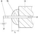
- the end cap 8 is fixed to the end face on one end side of the optical fiber 2.
- the end cap 8 is made of a coreless undoped quartz material having a single refractive index, and the refractive index is set to be equivalent to the refractive index of the core of the optical fiber 2.
- the outer shape is formed in a cylindrical shape and is set to the same diameter as the optical fiber 2. The optical fiber 2 and the end cap 8 are fused and fixed at respective end portions.
- the end portion of the end cap 8 is polished at an angle ⁇ (4 to 8 degrees) with respect to a plane perpendicular to the optical axis of the optical fiber 2 and formed in an inclined shape.
- the end face is subjected to an optical polishing process and an AR (Anti-Reflection) coat to suppress Fresnel reflection from the end face, thereby realizing an optical fiber assembly 1a with a small coupling loss.
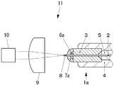
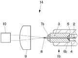
- FIG. 4 A schematic diagram of an optical coupling device 11 using the above optical fiber assembly 1a is shown in FIG.
- the optical fiber assembly 1a is shown in a sectional view. However, hatching of the optical fiber 2 and the end cap 8 is omitted for the sake of easy viewing.
- the optical coupling device 11 includes at least an optical fiber assembly 1 a and a light emitting element 10, and one end of the optical fiber 2 and an end face of the end cap 8 are disposed facing the light emitting element 10.
- FIG. 4 illustrates an optical coupling device 11 in which a lens 9 is disposed on one end side of the optical fiber 2 and an end surface on one end side is disposed to face the lens 9.
- the lens 9 (an example is a convex lens as shown in the figure) converges the laser light oscillated from the light emitting element 11 on the optical surface, and the end surface of the end cap 8 (or one end of the optical fiber 2 when the end cap 8 is not provided). Focus on. Further, the focal point is set substantially on the center of the end face of the end cap 8 (on the optical axis of the optical fiber 2 when there is no end cap 8).
- the light-emitting element 10 is a light source that oscillates a high-power laser beam having a wavelength band ranging from ultraviolet to infrared and having a laser output of 50 mW or more, such as an LD, a superluminescent diode, or a YAG laser.
- a solid laser or the like is used.
- the light emitting element 10 is housed inside a housing (not shown), the center of the end face of the end cap 8 is positioned with high precision at the focal position of the laser light by the lens 9, and an optical fiber assembly is mounted inside the housing with a support component (not shown).
- the optical coupling device 11 is manufactured by fixing 1a.
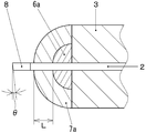
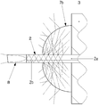
- FIG. 5 shows an enlarged cross section near one end of the optical fiber 2 in the optical fiber assembly 1a, and at least a part of the laser light emitted from the light emitting element 10 propagates as clad mode light in the optical fiber 2, and the clad
- FIG. 5 shows geometrically the state in which mode light scatters inside ceramics 7a.
- hatching of each part other than the capillary 3 is abbreviate
- a laser beam having a wavelength band ranging from ultraviolet to infrared is emitted from the light emitting element 10.
- the emitted laser light is converged by the lens 9 and enters the end face of the end cap 8, and further enters the optical fiber 2.
- the convergent light is centered on the end face of the end cap 8. Is incident.
- the laser light propagates through the end cap 8, and is incident on one end of the optical fiber 2 with a predetermined numerical aperture NA, and the inside of the core 2a is critical. It propagates while being totally reflected below the corner.
- FIG. 1 the laser beam is refracted at the end face of the end cap 8, propagates through the inside at a different incident angle, and enters the optical fiber 2.
- the laser light incident on the end cap 8 is incident on the optical fiber 2 while being gently refracted inside the end cap 8, and has a NA larger than the numerical aperture NA of the laser light or the core 2a in which the MFD mismatch occurs.
- Laser light is incident on the optical fiber 2 and clad mode light is generated.
- the refractive index of air (about 1.00) is smaller than the refractive index of the clad 2b (about 1.47 from the above), so that the clad mode light is transmitted to the outer periphery of the clad.
- the angle incident on the surface is larger than the critical angle, the clad mode light is confined in the optical fiber 2.
- the refractive index of the ceramic 7a is set to be higher than the refractive index of the clad 2b, so that the clad mode light is arranged in front of the fixing material 6a. Is incident on the inside of the ceramic 7a.
- the clad mode light incident on the ceramic 7a is scattered inside the ceramic 7a, and the scattered clad mode light is attenuated inside the ceramic 7a. Since the ceramic 7a is disposed in front of the position of the fixing member 6a when viewed from one end of the optical fiber 2, the clad mode light is scattered and attenuated inside the ceramic 7a. Further, since the ceramic 7a is in contact with the axial direction of the optical fiber 2 by a predetermined contact length L, the clad mode light is gradually attenuated in the axial direction of the optical fiber 2 while being attenuated inside the ceramic 7a. .
- the clad mode light propagating to the outside of the ceramic 7a is scattered in the axial direction of the optical fiber 2, and the scattered light in the axial direction of the optical fiber 2 is removed to prevent the clad mode light from entering the fixing material 6a.
- damage to the fixing material 6a can be prevented.
- the ceramic 7a is allowed to enter the cladding mode light and is scattered, and the scattered light in the axial direction of the optical fiber 2 is removed.
- the light is not incident on the fixing material 6a. Therefore, damage to the fixing material 6a can be prevented more reliably.
- the contact length L may be set to a predetermined length as long as the effect of preventing leakage of clad mode light to the fixing material 6a is obtained.
- the present applicant has found through verification that 0.3 mm or more is necessary as a length for completely preventing leakage of clad mode light to the fixing material 6a. Therefore, by setting the contact length L to 0.3 mm or more, the cladding mode light is more reliably scattered, the scattered light in the axial direction of the optical fiber 2 is removed, and the fixing material 6a is more reliably prevented from being damaged. It becomes possible to do.
- the exposed portion of the fixing material 6a is covered with the ceramic 7a so that the ceramic 7a is disposed in front of the fixing material 6a. Accordingly, the aberration of the lens 9, the misalignment between the light emitting element 10 and the incident end (or the end face of the end cap 8) of the optical fiber 2, or the incident end of the lens 9 and the optical fiber 2 (or the end face of the end cap 8). Even if high-power laser light emitted from the light emitting element 10 is emitted directly in the direction of the fixing material 6a due to misalignment of the laser beam, the laser light is diffusely reflected on the surface of the ceramic 7a, and the fixing material 6a Not incident. Therefore, the outgoing light from the light emitting element 10 that has leaked the coupling is diffusely reflected to prevent the outgoing light from being directly incident on the fixing material 6a. Damage to 6a can be prevented.
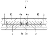
- a plurality of optical fiber assemblies 1a are arranged in a plurality of cylindrical cases 12 so that one end of each optical fiber 2 is opposed to each other, thereby constituting an optical fiber coupling device 13. You may do it.
- the same number is attached
- the optical axes configured such that the core axes of the optical fibers 2 are arranged on the same straight line and one ends of the optical fibers 2 arranged to face each other are in contact with each other.
- a coupling device 13 is shown.
- each optical fiber 2 may be separated from each other, and an optical element such as a collimator lens, a filter, or an optical isolator may be disposed between each separated optical fiber 2.
- an optical element such as a collimator lens, a filter, or an optical isolator
- clad mode light may be generated by the coupling.
- the ceramics 7a are arranged in front of the fixing material 6a in each optical fiber 2, the clad mode light is scattered, attenuated, and removed inside the ceramics 7a as in the case of the optical coupling device 11, and is applied to the fixing material 6a. Incidence of clad mode light is prevented, and damage to the fixing material 6a is prevented.
- FIGS. 7 to 9 a second embodiment of the optical fiber assembly according to the present invention will be described with reference to FIGS. 7 to 9, and the configuration and operation of an optical coupling device using the optical fiber assembly of the second embodiment. Will be described with reference to FIGS.
- the configuration and operation of an optical fiber coupling device using the optical fiber assembly of the second embodiment will be described with reference to FIG.
- the same number is attached
- the hatching of the optical fiber 2 and the end cap 8 is omitted for the sake of easy viewing. Further, in FIG. 11, hatching of each part other than the capillary 3 is omitted.
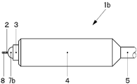
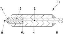
- the optical fiber assembly 1b according to the second embodiment is different from the optical fiber assembly 1a in that the fixing material 6b is provided at the end of the capillary 3 through-hole on the other end side opposite to the one end side of the optical fiber 2. Further, only the ceramic 7b is disposed at the end of the through hole on one end side of the optical fiber 2.
- the outer periphery of the optical fiber 2 and the capillary 3 in the optical fiber assembly 1b are fixed by disposing a fixing member 6b at the end of the through hole on the other end side of the optical fiber 2 as shown in FIG.
- the adhesive or the solder may be used for the fixing material 6b.
- the low melting point glass is not used at the position where the fixing member 6b is disposed because the coating 5 of the optical fiber 2 may be burned by the heating temperature.
- the ceramic 7b is provided so as to be in contact with the entire outer periphery of the optical fiber 2, and is disposed with a predetermined contact length L in the axial direction of the optical fiber 2 as shown in FIG. Therefore, the arrangement position of the ceramic 7b is set in front of the position of the fixing member 6b in contact with the outer periphery of the optical fiber 2 when viewed from one end of the optical fiber 2.
- the ceramic 7b has a refractive index set to be equal to or higher than the refractive index of the clad of the optical fiber 2 (particularly, the outer periphery of the clad) in the wavelength band ranging from ultraviolet to infrared. Furthermore, all ceramic materials having the characteristic of scattering and removing light incident on the ceramic 7b are covered. Accordingly, when clad mode light is incident from one end of the optical fiber 2, the clad mode light is incident inside the ceramic 7b.
- the ceramic 7b is applied by applying a paste-like ceramic base material adhesive to the end of the through-hole of the capillary 3 on one end side of the optical fiber 2 in a normal temperature range (5 ° C. to 35 ° C.), and then 100 ° C. Heat and cure with
- the refractive index of air (about 1.00) is around the cladding 2b on the outer periphery of the cladding 2b as shown in FIG. Therefore, when the angle at which the clad mode light is incident on the outer peripheral surface of the clad is larger than the critical angle, the clad mode light is confined in the optical fiber 2.
- the refractive index of the ceramic 7b is set to be equal to or higher than the refractive index of the clad 2b, so that the clad mode light is arranged in front of the fixing material 6b. It enters the inside of the ceramic 7b.
- the clad mode light incident on the ceramic 7b is scattered and attenuated inside the ceramic 7b. Further, since the ceramic 7b is in contact with the axial direction of the optical fiber 2 by a predetermined contact length L, the ceramic 7b is gradually attenuated in the axial direction of the optical fiber 2. As described above, the scattered light in the axial direction of the optical fiber 2 is removed, the clad mode light is prevented from entering the fixing material 6b, and the fixing material 6b can be prevented from being damaged.
- the coupling of laser light having a larger NA than the core NA of each optical fiber 2 or the mismatch of MFD may be generated due to the coupling of the laser light generated.
- the ceramics 7b are disposed in front of the fixing material 6b in each optical fiber 2, the clad mode light is scattered, attenuated, and removed inside the ceramics 7b similarly to the optical coupling device 14, and is applied to the fixing material 6b. The incidence of the clad mode light is prevented, and the fixing material 6b is prevented from being damaged.
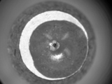
- the optical fiber assembly according to this example has the configuration of the optical fiber assembly 1a shown in FIG. 2, and a panda type polarization maintaining fiber is used as the optical fiber. Further, PbO—B 2 O 3 low melting glass was used as the fixing material, and alumina was used as the ceramic. Further, the contact length L was set to be within 0.5 mm to 1.0 mm over the entire circumference of the optical fiber. On the other hand, a light source having a blue band with wavelengths of 405, 450 and 488 nm and a laser output of 50 mW was used as the light emitting element.
- the laser light was incident on the optical fiber from the light source, the clad mode light was propagated inside the optical fiber, and the state of alumina was observed.
- the state of alumina is shown in FIG. From FIG. 14, no change was observed in the state of alumina, and no change was observed in the low melting point glass. Therefore, it was confirmed that the clad mode light was scattered and removed inside the alumina.
- the resistance was evaluated by direct incidence of laser light from a light source so as to focus on the alumina surface. As a result, it was observed that the laser light was diffusely reflected on the surface of the alumina and no change occurred in the state of alumina as shown in FIG. Therefore, an evaluation result was obtained that this example had resistance to light emitted from the light source.
- the laser light was incident on the optical fiber from the light source, the clad mode light was propagated inside the optical fiber, and the state of the low melting point glass was observed.
- the state of the low melting point glass is shown in FIG. From FIG. 15, blackening of the low melting point glass was observed. Therefore, it was confirmed that the fixing material was damaged due to the leakage of the clad mode light.
- FIG. 16 shows the surface state of the low-melting glass before direct irradiation with laser light
- FIG. 17 shows the surface state of the low-melting glass after direct irradiation with laser light.
- blackening occurred in the laser beam condensing part on the surface of the low melting point glass after the laser beam irradiation, and white precipitates were observed around it. Accordingly, an evaluation result was obtained that the comparative example did not have resistance to the light emitted from the light source.
Landscapes
- Physics & Mathematics (AREA)
- General Physics & Mathematics (AREA)
- Optics & Photonics (AREA)
- Optical Couplings Of Light Guides (AREA)
- Mechanical Coupling Of Light Guides (AREA)
Abstract
Description
(1)本発明の光ファイバアセンブリは、少なくとも光ファイバ及びこの光ファイバを挿入する貫通孔を有するキャピラリで構成され、更に光ファイバが、コアと、コアの屈折率よりも小さい屈折率を有してコアの周りを包囲するクラッドで構成され、キャピラリの貫通孔に光ファイバが挿入され、更に光ファイバの一端がキャピラリの外部に突出されており、光ファイバの外周とキャピラリとが固定材で固定され、更に光ファイバの外周の全周に亘って接触されると共に光ファイバの軸方向に所定の接触長を有してセラミックスが配置され、光ファイバの一端から見て、光ファイバ外周と接触される固定材の位置よりも前方に、セラミックスの配置位置が設定されていることを特徴とする。
以下に、本発明に係る光ファイバアセンブリの第1の実施形態について、図1から図3を参照しながら説明する。図1は、本発明の第1の実施形態に係る光ファイバアセンブリ1aの構成を示す模式図であり、図2は光ファイバアセンブリ1aの構成を模式的に示す断面図であり、図3は光ファイバアセンブリ1aにおける、光ファイバ2の一端側付近の拡大部分断面図である。なお、図2及び図3では見易さを優先し、後述する光ファイバ2とエンドキャップ8のハッチングを省略している。
次に、本発明に係る光ファイバアセンブリの第2の実施形態について、図7から図9を参照しながら説明すると共に、第2の実施形態の光ファイバアセンブリを使用した光結合装置の構成と動作を図10及び図11を参照しながら説明する。また、第2の実施形態の光ファイバアセンブリを使用した光ファイバ結合装置の構成と動作を、図12を参照しながら説明する。なお、第1の実施形態と同一箇所には同一番号を付し、重複する説明は省略又は簡略化する。図8から図10、及び図12でも見易さを優先して、光ファイバ2とエンドキャップ8のハッチングを省略している。更に、図11ではキャピラリ3以外の各部のハッチングは省略している。
以下に本発明の実施例を説明するが、本発明は以下の実施例にのみ限定されるものではない。本実施例に係る光ファイバアセンブリは、図2に示す光ファイバアセンブリ1aの構成とし、光ファイバとしてパンダ型の偏波保持ファイバを用いた。また、固定材としてPbO-B2O3系低融点ガラスを用いると共に、セラミックスにはアルミナを用いた。更に、接触長Lは光ファイバの全周に亘って0.5mmから1.0mm内に収まるように設定した。一方発光素子には、波長405、450、488nmの青色帯域を有すると共に、レーザ出力が50mWの光源を用いた。
次に比較例として、図2に示す光ファイバアセンブリ1aにおいてセラミックス7aを備えない光ファイバアセンブリを、サンプルとして用意した。セラミックスの有無以外は、前記実施例と同一の構成とした。なお発光素子には、実施例と同一の光源を使用した。
2 光ファイバ
2a コア
2b クラッド
3 キャピラリ
4 スリーブ
5 被覆
6a、6b 固定材
7a、7b セラミックス
8 エンドキャップ
9 レンズ
10 発光素子
11、14 光結合装置
12 ケース
13、15 光ファイバ結合装置
16 偏波保持ファイバの素線
16a 偏波保持ファイバのコア
16b 偏波保持ファイバのクラッド
16c 偏波保持ファイバの応力付与部
L 光ファイバ外周とセラミックスとの接触長
θ エンドキャップ端部の傾斜角度
Claims (6)
- 少なくとも光ファイバ及びこの光ファイバを挿入する貫通孔を有するキャピラリで構成され、
更に光ファイバが、コアと、コアの屈折率よりも小さい屈折率を有してコアの周りを包囲するクラッドで構成され、
キャピラリの貫通孔に光ファイバが挿入され、更に光ファイバの一端がキャピラリの外部に突出されており、
光ファイバの外周とキャピラリとが固定材で固定され、
更に光ファイバの外周の全周に亘って接触されると共に光ファイバの軸方向に所定の接触長を有してセラミックスが配置され、
光ファイバの一端から見て、光ファイバ外周と接触される固定材の位置よりも前方に、セラミックスの配置位置が設定されていることを特徴とする光ファイバアセンブリ。 - 前記セラミックスに入射された光が散乱されると共に、前記セラミックスの屈折率が前記クラッドの屈折率以上に設定されていることを特徴とする請求項1記載の光ファイバアセンブリ。
- 前記接触長が0.3mm以上であることを特徴とする請求項1又は2に記載の光ファイバアセンブリ。
- 前記光ファイバの前記一端側の前記貫通孔の端部に前記固定材が配置され、更に前記固定材が前記セラミックスで覆われていることを特徴とする請求項1~3の何れかに記載の光ファイバアセンブリ。
- 請求項1~4の何れかに記載の光ファイバアセンブリと発光素子で少なくとも構成され、
発光素子に対向して前記一端が配置されていることを特徴とする光結合装置。 - 請求項1~4の何れかに記載の光ファイバアセンブリを複数備えて構成され、各光ファイバの前記一端が対向配置されていることを特徴とする光ファイバ結合装置。
Priority Applications (4)
| Application Number | Priority Date | Filing Date | Title |
|---|---|---|---|
| US15/301,769 US9841570B2 (en) | 2014-04-10 | 2015-04-09 | Optical fiber assembly, optical coupling device, and optical fiber coupling device |
| EP15777474.6A EP3130951B1 (en) | 2014-04-10 | 2015-04-09 | Optical fiber assembly, optical coupling device, and optical fiber coupling device |
| CN201580018921.3A CN106170726B (zh) | 2014-04-10 | 2015-04-09 | 光纤组件及光耦合装置、光纤耦合装置 |
| JP2016512607A JP6678286B2 (ja) | 2014-04-10 | 2015-04-09 | 光ファイバアセンブリ及び光結合装置、光ファイバ結合装置 |
Applications Claiming Priority (2)
| Application Number | Priority Date | Filing Date | Title |
|---|---|---|---|
| JP2014081344 | 2014-04-10 | ||
| JP2014-081344 | 2014-04-10 |
Publications (1)
| Publication Number | Publication Date |
|---|---|
| WO2015155994A1 true WO2015155994A1 (ja) | 2015-10-15 |
Family
ID=54287578
Family Applications (1)
| Application Number | Title | Priority Date | Filing Date |
|---|---|---|---|
| PCT/JP2015/002015 WO2015155994A1 (ja) | 2014-04-10 | 2015-04-09 | 光ファイバアセンブリ及び光結合装置、光ファイバ結合装置 |
Country Status (5)
| Country | Link |
|---|---|
| US (1) | US9841570B2 (ja) |
| EP (1) | EP3130951B1 (ja) |
| JP (1) | JP6678286B2 (ja) |
| CN (1) | CN106170726B (ja) |
| WO (1) | WO2015155994A1 (ja) |
Cited By (2)
| Publication number | Priority date | Publication date | Assignee | Title |
|---|---|---|---|---|
| EP3367520A1 (en) * | 2015-01-22 | 2018-08-29 | Trumpf Photonics, Inc. | Arrangement of multiple diode laser module and method of operating the same |
| JP2019192834A (ja) * | 2018-04-26 | 2019-10-31 | 株式会社フジクラ | ガラスブロック、光ファイバ終端構造、レーザ装置、及びレーザシステム |
Families Citing this family (6)
| Publication number | Priority date | Publication date | Assignee | Title |
|---|---|---|---|---|
| US10548489B2 (en) * | 2014-10-31 | 2020-02-04 | Lake Region Medical, Inc. | Fiber Bragg grating multi-point pressure sensing guidewire with birefringent component |
| CN105870767B (zh) * | 2016-05-03 | 2019-03-19 | 中电科天之星激光技术(上海)有限公司 | 一种指向可调的光纤输出激光发生器 |
| US20210001115A1 (en) * | 2019-07-01 | 2021-01-07 | Wavegate Corporation | Surgical electrode and lead for use with implanted pulse generator and method of use |
| CN111399138A (zh) * | 2020-06-05 | 2020-07-10 | 苏州长光华芯光电技术有限公司 | 一种光纤耦合散热结构及光纤输入头 |
| CN114578488B (zh) * | 2020-12-01 | 2024-03-12 | 深南电路股份有限公司 | 光纤线路板单元、光传输装置以及光电混合线路板 |
| CN113075763B (zh) * | 2021-03-11 | 2022-07-15 | 武汉长盈通光电技术股份有限公司 | 多芯熊猫结构保偏光纤及其耦合连接装置 |
Citations (8)
| Publication number | Priority date | Publication date | Assignee | Title |
|---|---|---|---|---|
| JPS5632809U (ja) * | 1979-08-21 | 1981-03-31 | ||
| JPS5997110A (ja) * | 1982-11-27 | 1984-06-04 | Toshiba Corp | 光フアイバ用コネクタ |
| JPS6122009U (ja) * | 1984-07-13 | 1986-02-08 | 三菱電線工業株式会社 | 高エネルギビ−ム用コネクタ |
| JPH0527707U (ja) * | 1991-09-20 | 1993-04-09 | 三菱電機株式会社 | 光フアイバ端末 |
| JP2001083369A (ja) * | 1999-09-10 | 2001-03-30 | Furukawa Electric Co Ltd:The | 光ファイバ用フェルールおよびそれを用いた半導体レーザモジュール |
| JP2001194623A (ja) * | 1999-10-29 | 2001-07-19 | Kyocera Corp | ファイバスタブ型光デバイス及びそれを用いた光モジュール |
| JP2011186399A (ja) * | 2010-03-11 | 2011-09-22 | Omron Corp | 光ファイバ接続構造、レーザ照射装置およびレーザ加工装置 |
| EP2479594A1 (en) * | 2011-01-21 | 2012-07-25 | Oclaro Technology Limited | Robust pigtail system for high power laser modules |
Family Cites Families (15)
| Publication number | Priority date | Publication date | Assignee | Title |
|---|---|---|---|---|
| US4737011A (en) | 1984-07-13 | 1988-04-12 | Dainichi-Nippon Cables Ltd. | Connector for high energy beam |
| JP3530757B2 (ja) | 1998-09-03 | 2004-05-24 | 新光電気工業株式会社 | 光ファイバ用フェルールの気密構造 |
| FR2797058A1 (fr) | 1999-07-29 | 2001-02-02 | Kyocera Corp | Dispositif du type a troncon de fibre et module optique l'utilisant et procede de fabrication d'un dispositif du type a troncon de fibre |
| JP2001051166A (ja) * | 1999-08-12 | 2001-02-23 | Furukawa Electric Co Ltd:The | 半導体レーザモジュール |
| JP2003014988A (ja) * | 2001-06-28 | 2003-01-15 | Ykk Corp | 光コネクタ及びそれに用いる光コネクタ用フェルール |
| JP2003121689A (ja) * | 2001-08-06 | 2003-04-23 | Nippon Sheet Glass Co Ltd | 光モジュールおよびその組立方法 |
| JP2005134696A (ja) * | 2003-10-31 | 2005-05-26 | Yokogawa Electric Corp | フェルールおよびフェルール付き光ファイバ |
| JP2005156921A (ja) * | 2003-11-26 | 2005-06-16 | Yokogawa Electric Corp | フェルール、フェルール付き光ファイバおよびフェルール付き光ファイバを用いた装置 |
| KR20060076205A (ko) * | 2004-12-28 | 2006-07-04 | 프레사이스 게이지 가부시키가이샤 | 광부품의 제조방법 및 제조장치, 및 광부품 |
| US8425500B2 (en) * | 2008-05-19 | 2013-04-23 | Boston Scientific Scimed, Inc. | Method and apparatus for protecting capillary of laser fiber during insertion and reducing metal cap degradation |
| WO2011030306A1 (en) * | 2009-09-09 | 2011-03-17 | Thinkeco Power Inc. | Method and system of aggregating and delivering electrical power using fiber optic cables |
| WO2011075442A1 (en) * | 2009-12-15 | 2011-06-23 | Omniguide, Inc. | Two-part surgical waveguide |
| WO2012121318A1 (ja) * | 2011-03-09 | 2012-09-13 | 古河電気工業株式会社 | 光コネクタ、マルチコアファイバとバンドル構造との調芯方法、ファイバ配列変換部材 |
| WO2012167102A1 (en) * | 2011-06-03 | 2012-12-06 | Foro Energy Inc. | Rugged passively cooled high power laser fiber optic connectors and methods of use |
| US20130331689A1 (en) * | 2012-06-07 | 2013-12-12 | Poincare Systems, Inc. | Rotating shaft containing optical waveguide |
-
2015
- 2015-04-09 CN CN201580018921.3A patent/CN106170726B/zh active Active
- 2015-04-09 US US15/301,769 patent/US9841570B2/en active Active
- 2015-04-09 JP JP2016512607A patent/JP6678286B2/ja active Active
- 2015-04-09 EP EP15777474.6A patent/EP3130951B1/en active Active
- 2015-04-09 WO PCT/JP2015/002015 patent/WO2015155994A1/ja active Application Filing
Patent Citations (8)
| Publication number | Priority date | Publication date | Assignee | Title |
|---|---|---|---|---|
| JPS5632809U (ja) * | 1979-08-21 | 1981-03-31 | ||
| JPS5997110A (ja) * | 1982-11-27 | 1984-06-04 | Toshiba Corp | 光フアイバ用コネクタ |
| JPS6122009U (ja) * | 1984-07-13 | 1986-02-08 | 三菱電線工業株式会社 | 高エネルギビ−ム用コネクタ |
| JPH0527707U (ja) * | 1991-09-20 | 1993-04-09 | 三菱電機株式会社 | 光フアイバ端末 |
| JP2001083369A (ja) * | 1999-09-10 | 2001-03-30 | Furukawa Electric Co Ltd:The | 光ファイバ用フェルールおよびそれを用いた半導体レーザモジュール |
| JP2001194623A (ja) * | 1999-10-29 | 2001-07-19 | Kyocera Corp | ファイバスタブ型光デバイス及びそれを用いた光モジュール |
| JP2011186399A (ja) * | 2010-03-11 | 2011-09-22 | Omron Corp | 光ファイバ接続構造、レーザ照射装置およびレーザ加工装置 |
| EP2479594A1 (en) * | 2011-01-21 | 2012-07-25 | Oclaro Technology Limited | Robust pigtail system for high power laser modules |
Non-Patent Citations (1)
| Title |
|---|
| See also references of EP3130951A4 * |
Cited By (3)
| Publication number | Priority date | Publication date | Assignee | Title |
|---|---|---|---|---|
| EP3367520A1 (en) * | 2015-01-22 | 2018-08-29 | Trumpf Photonics, Inc. | Arrangement of multiple diode laser module and method of operating the same |
| JP2019192834A (ja) * | 2018-04-26 | 2019-10-31 | 株式会社フジクラ | ガラスブロック、光ファイバ終端構造、レーザ装置、及びレーザシステム |
| WO2019207902A1 (ja) * | 2018-04-26 | 2019-10-31 | 株式会社フジクラ | ガラスブロック、光ファイバ終端構造、レーザ装置、及びレーザシステム |
Also Published As
| Publication number | Publication date |
|---|---|
| EP3130951A4 (en) | 2017-11-01 |
| EP3130951A1 (en) | 2017-02-15 |
| JP6678286B2 (ja) | 2020-04-08 |
| JPWO2015155994A1 (ja) | 2017-04-13 |
| US20170031111A1 (en) | 2017-02-02 |
| CN106170726A (zh) | 2016-11-30 |
| US9841570B2 (en) | 2017-12-12 |
| CN106170726B (zh) | 2019-04-09 |
| EP3130951B1 (en) | 2021-08-11 |
Similar Documents
| Publication | Publication Date | Title |
|---|---|---|
| WO2015155994A1 (ja) | 光ファイバアセンブリ及び光結合装置、光ファイバ結合装置 | |
| US7306376B2 (en) | Monolithic mode stripping fiber ferrule/collimator and method of making same | |
| JP4817013B2 (ja) | 光デバイス及びレンズアッセンブリ | |
| JP2007193006A (ja) | 光通信用光学部品 | |
| US9213140B2 (en) | Fiber component and laser device | |
| WO2007116792A1 (ja) | 光学部品の光入出力端およびビーム変換装置 | |
| WO2014208701A1 (ja) | 光レセプタクル | |
| US9453967B2 (en) | High power misalignment-tolerant fiber assembly | |
| US7099552B1 (en) | Optical terminator | |
| WO2018062484A1 (ja) | 光接続構造、光モジュール | |
| US7397985B2 (en) | High-power fused collimator and associated methods | |
| JP2007293300A (ja) | ビーム変換装置 | |
| JP2014193806A5 (ja) | ||
| JP2015175958A (ja) | 半導体レーザモジュール、半導体レーザ光源及び半導体レーザシステム | |
| WO2018181782A1 (ja) | 光レセプタクル及び光トランシーバ | |
| JP6026147B2 (ja) | 光コネクタ | |
| US20210124138A1 (en) | Light source device | |
| JP2002040271A (ja) | 光ファイバの端末構造及び光ファイバの端末処理方法 | |
| WO2014129280A1 (ja) | 光コネクタ装置 | |
| CN110646895B (zh) | 光插座及光收发器 | |
| WO2020196562A1 (ja) | 光ファイバにおける端部構造および半導体レーザモジュール | |
| JP2010079256A (ja) | 光ファイバピグテイル | |
| JP7012414B2 (ja) | 端部構造および半導体レーザモジュール | |
| JP5856016B2 (ja) | 光モジュール | |
| JP2007226182A (ja) | 光アイソレータ付き光ファイバ保持部品およびそれを用いた光レセプタクルならびに光モジュール |
Legal Events
| Date | Code | Title | Description |
|---|---|---|---|
| 121 | Ep: the epo has been informed by wipo that ep was designated in this application |
Ref document number: 15777474 Country of ref document: EP Kind code of ref document: A1 |
|
| ENP | Entry into the national phase |
Ref document number: 2016512607 Country of ref document: JP Kind code of ref document: A |
|
| WWE | Wipo information: entry into national phase |
Ref document number: 15301769 Country of ref document: US |
|
| REEP | Request for entry into the european phase |
Ref document number: 2015777474 Country of ref document: EP |
|
| WWE | Wipo information: entry into national phase |
Ref document number: 2015777474 Country of ref document: EP |
|
| NENP | Non-entry into the national phase |
Ref country code: DE |