WO2015151936A1 - Moule de moulage par injection - Google Patents
Moule de moulage par injection Download PDFInfo
- Publication number
- WO2015151936A1 WO2015151936A1 PCT/JP2015/058948 JP2015058948W WO2015151936A1 WO 2015151936 A1 WO2015151936 A1 WO 2015151936A1 JP 2015058948 W JP2015058948 W JP 2015058948W WO 2015151936 A1 WO2015151936 A1 WO 2015151936A1
- Authority
- WO
- WIPO (PCT)
- Prior art keywords
- needle
- injection
- pin
- injection needle
- tip
- Prior art date
Links
Images


Classifications
-
- A—HUMAN NECESSITIES
- A61—MEDICAL OR VETERINARY SCIENCE; HYGIENE
- A61M—DEVICES FOR INTRODUCING MEDIA INTO, OR ONTO, THE BODY; DEVICES FOR TRANSDUCING BODY MEDIA OR FOR TAKING MEDIA FROM THE BODY; DEVICES FOR PRODUCING OR ENDING SLEEP OR STUPOR
- A61M5/00—Devices for bringing media into the body in a subcutaneous, intra-vascular or intramuscular way; Accessories therefor, e.g. filling or cleaning devices, arm-rests
- A61M5/178—Syringes
- A61M5/31—Details
- A61M5/32—Needles; Details of needles pertaining to their connection with syringe or hub; Accessories for bringing the needle into, or holding the needle on, the body; Devices for protection of needles
- A61M5/34—Constructions for connecting the needle, e.g. to syringe nozzle or needle hub
-
- A—HUMAN NECESSITIES
- A61—MEDICAL OR VETERINARY SCIENCE; HYGIENE
- A61M—DEVICES FOR INTRODUCING MEDIA INTO, OR ONTO, THE BODY; DEVICES FOR TRANSDUCING BODY MEDIA OR FOR TAKING MEDIA FROM THE BODY; DEVICES FOR PRODUCING OR ENDING SLEEP OR STUPOR
- A61M5/00—Devices for bringing media into the body in a subcutaneous, intra-vascular or intramuscular way; Accessories therefor, e.g. filling or cleaning devices, arm-rests
- A61M5/178—Syringes
- A61M5/31—Details
- A61M5/3129—Syringe barrels
-
- B—PERFORMING OPERATIONS; TRANSPORTING
- B29—WORKING OF PLASTICS; WORKING OF SUBSTANCES IN A PLASTIC STATE IN GENERAL
- B29C—SHAPING OR JOINING OF PLASTICS; SHAPING OF MATERIAL IN A PLASTIC STATE, NOT OTHERWISE PROVIDED FOR; AFTER-TREATMENT OF THE SHAPED PRODUCTS, e.g. REPAIRING
- B29C45/00—Injection moulding, i.e. forcing the required volume of moulding material through a nozzle into a closed mould; Apparatus therefor
- B29C45/14—Injection moulding, i.e. forcing the required volume of moulding material through a nozzle into a closed mould; Apparatus therefor incorporating preformed parts or layers, e.g. injection moulding around inserts or for coating articles
- B29C45/14065—Positioning or centering articles in the mould
-
- A—HUMAN NECESSITIES
- A61—MEDICAL OR VETERINARY SCIENCE; HYGIENE
- A61M—DEVICES FOR INTRODUCING MEDIA INTO, OR ONTO, THE BODY; DEVICES FOR TRANSDUCING BODY MEDIA OR FOR TAKING MEDIA FROM THE BODY; DEVICES FOR PRODUCING OR ENDING SLEEP OR STUPOR
- A61M2207/00—Methods of manufacture, assembly or production
-
- A—HUMAN NECESSITIES
- A61—MEDICAL OR VETERINARY SCIENCE; HYGIENE
- A61M—DEVICES FOR INTRODUCING MEDIA INTO, OR ONTO, THE BODY; DEVICES FOR TRANSDUCING BODY MEDIA OR FOR TAKING MEDIA FROM THE BODY; DEVICES FOR PRODUCING OR ENDING SLEEP OR STUPOR
- A61M5/00—Devices for bringing media into the body in a subcutaneous, intra-vascular or intramuscular way; Accessories therefor, e.g. filling or cleaning devices, arm-rests
- A61M5/178—Syringes
- A61M5/28—Syringe ampoules or carpules, i.e. ampoules or carpules provided with a needle
-
- A—HUMAN NECESSITIES
- A61—MEDICAL OR VETERINARY SCIENCE; HYGIENE
- A61M—DEVICES FOR INTRODUCING MEDIA INTO, OR ONTO, THE BODY; DEVICES FOR TRANSDUCING BODY MEDIA OR FOR TAKING MEDIA FROM THE BODY; DEVICES FOR PRODUCING OR ENDING SLEEP OR STUPOR
- A61M5/00—Devices for bringing media into the body in a subcutaneous, intra-vascular or intramuscular way; Accessories therefor, e.g. filling or cleaning devices, arm-rests
- A61M5/178—Syringes
- A61M5/31—Details
- A61M5/32—Needles; Details of needles pertaining to their connection with syringe or hub; Accessories for bringing the needle into, or holding the needle on, the body; Devices for protection of needles
- A61M5/34—Constructions for connecting the needle, e.g. to syringe nozzle or needle hub
- A61M5/343—Connection of needle cannula to needle hub, or directly to syringe nozzle without a needle hub
-
- B—PERFORMING OPERATIONS; TRANSPORTING
- B29—WORKING OF PLASTICS; WORKING OF SUBSTANCES IN A PLASTIC STATE IN GENERAL
- B29C—SHAPING OR JOINING OF PLASTICS; SHAPING OF MATERIAL IN A PLASTIC STATE, NOT OTHERWISE PROVIDED FOR; AFTER-TREATMENT OF THE SHAPED PRODUCTS, e.g. REPAIRING
- B29C45/00—Injection moulding, i.e. forcing the required volume of moulding material through a nozzle into a closed mould; Apparatus therefor
- B29C45/0025—Preventing defects on the moulded article, e.g. weld lines, shrinkage marks
- B29C2045/0027—Gate or gate mark locations
-
- B—PERFORMING OPERATIONS; TRANSPORTING
- B29—WORKING OF PLASTICS; WORKING OF SUBSTANCES IN A PLASTIC STATE IN GENERAL
- B29C—SHAPING OR JOINING OF PLASTICS; SHAPING OF MATERIAL IN A PLASTIC STATE, NOT OTHERWISE PROVIDED FOR; AFTER-TREATMENT OF THE SHAPED PRODUCTS, e.g. REPAIRING
- B29C45/00—Injection moulding, i.e. forcing the required volume of moulding material through a nozzle into a closed mould; Apparatus therefor
- B29C45/14—Injection moulding, i.e. forcing the required volume of moulding material through a nozzle into a closed mould; Apparatus therefor incorporating preformed parts or layers, e.g. injection moulding around inserts or for coating articles
- B29C45/14065—Positioning or centering articles in the mould
- B29C2045/14139—Positioning or centering articles in the mould positioning inserts having a part extending into a positioning cavity outside the mould cavity
-
- B—PERFORMING OPERATIONS; TRANSPORTING
- B29—WORKING OF PLASTICS; WORKING OF SUBSTANCES IN A PLASTIC STATE IN GENERAL
- B29C—SHAPING OR JOINING OF PLASTICS; SHAPING OF MATERIAL IN A PLASTIC STATE, NOT OTHERWISE PROVIDED FOR; AFTER-TREATMENT OF THE SHAPED PRODUCTS, e.g. REPAIRING
- B29C45/00—Injection moulding, i.e. forcing the required volume of moulding material through a nozzle into a closed mould; Apparatus therefor
- B29C45/14—Injection moulding, i.e. forcing the required volume of moulding material through a nozzle into a closed mould; Apparatus therefor incorporating preformed parts or layers, e.g. injection moulding around inserts or for coating articles
- B29C45/14336—Coating a portion of the article, e.g. the edge of the article
- B29C45/14418—Sealing means between mould and article
-
- B—PERFORMING OPERATIONS; TRANSPORTING
- B29—WORKING OF PLASTICS; WORKING OF SUBSTANCES IN A PLASTIC STATE IN GENERAL
- B29C—SHAPING OR JOINING OF PLASTICS; SHAPING OF MATERIAL IN A PLASTIC STATE, NOT OTHERWISE PROVIDED FOR; AFTER-TREATMENT OF THE SHAPED PRODUCTS, e.g. REPAIRING
- B29C45/00—Injection moulding, i.e. forcing the required volume of moulding material through a nozzle into a closed mould; Apparatus therefor
- B29C45/14—Injection moulding, i.e. forcing the required volume of moulding material through a nozzle into a closed mould; Apparatus therefor incorporating preformed parts or layers, e.g. injection moulding around inserts or for coating articles
- B29C45/14336—Coating a portion of the article, e.g. the edge of the article
- B29C45/14426—Coating the end of wire-like or rod-like or cable-like or blade-like or belt-like articles
-
- B—PERFORMING OPERATIONS; TRANSPORTING
- B29—WORKING OF PLASTICS; WORKING OF SUBSTANCES IN A PLASTIC STATE IN GENERAL
- B29C—SHAPING OR JOINING OF PLASTICS; SHAPING OF MATERIAL IN A PLASTIC STATE, NOT OTHERWISE PROVIDED FOR; AFTER-TREATMENT OF THE SHAPED PRODUCTS, e.g. REPAIRING
- B29C45/00—Injection moulding, i.e. forcing the required volume of moulding material through a nozzle into a closed mould; Apparatus therefor
- B29C45/14—Injection moulding, i.e. forcing the required volume of moulding material through a nozzle into a closed mould; Apparatus therefor incorporating preformed parts or layers, e.g. injection moulding around inserts or for coating articles
- B29C45/14598—Coating tubular articles
-
- B—PERFORMING OPERATIONS; TRANSPORTING
- B29—WORKING OF PLASTICS; WORKING OF SUBSTANCES IN A PLASTIC STATE IN GENERAL
- B29L—INDEXING SCHEME ASSOCIATED WITH SUBCLASS B29C, RELATING TO PARTICULAR ARTICLES
- B29L2031/00—Other particular articles
- B29L2031/753—Medical equipment; Accessories therefor
- B29L2031/7544—Injection needles, syringes
Definitions
- the present invention relates to an injection mold used for molding a syringe with a needle for injecting a small amount of a chemical solution subcutaneously, and a method for manufacturing a syringe with a needle using the same.
- a syringe with a needle is a syringe in which a small-diameter injection needle is previously passed through and fixed to the end of an outer cylinder that becomes an injection cylinder.
- a syringe with a needle is a hypodermic rather than intravenous injection because a small amount of drug solution in the outer cylinder can be quickly discharged from the injection needle by pressing strongly with a pusher fitted with a gasket at the tip and inserted in the outer cylinder. Used for. Since this syringe with a needle has an injection needle fixed to the outer cylinder, it does not require a cumbersome operation of attaching a separate injection needle base immediately before administration, and can easily and efficiently administer a drug solution. Has been.
- the syringe with a needle was manufactured by preparing an outer cylinder having an insertion hole at the end of the cylinder, and adhering with an adhesive while inserting the injection needle into the insertion hole.
- the dose of a biologic such as a vaccine to be injected subcutaneously is as small as about 500 ⁇ L for pain relief at the time of administration.
- This syringe with a needle is because the bonded injection needle has a small diameter, and when a small amount of drug solution is administered, the pressing force on the pusher tends to be too high, and the injection needle may come out of the tip of the cylinder.
- the conventional injection mold used for manufacturing the syringe with a needle has a raised portion 11 for supporting the injection needle 61 deeply inserted into the tip of the core pin 13 and supporting it independently. It comprises a male mold 10 provided and a female mold 20 for molding the outer surface of the outer cylinder. If the insertion of the injection needle 61 into the raised portion 11 is shallow, the injection needle 61 tilts in the middle of the formation of the cavity space 20a, and the central axis of the injection needle 61 of the syringe with needle molded by the subsequent resin injection is the outer cylinder. It may be inclined with respect to the central axis. Therefore, the raised portion 11 is provided to be somewhat high and thick so that the injection needle 61 can be inserted deeply.
- a deep and wide hollow portion transferred from the raised portion 11 is formed on the inner wall of the outer end of the molded outer tube. Since the injection needle is fixed so that the proximal end portion of the needle fits in the hollow portion, the hollow portion becomes a dead space.
- the drug solution filled in the depression reaches several tens to hundreds of ⁇ L.
- the tip of the gasket comes into contact with the inner wall of the outer tube, and the gasket can no longer be pressed. For this reason, the chemical liquid filled in the hollow portion cannot be pushed out, and remains as it is not discharged, resulting in a waste.
- the present invention has been made to solve the above-mentioned problems, and is for injection molding that can manufacture a syringe with a needle that can be fixed to an outer cylinder without inclining the injection needle and that can reduce the dead space that cannot discharge the filling liquid.
- a method of manufacturing a syringe with a needle that can be manufactured easily and with a high yield by using as many molds as possible using the mold, and the mold for injection molding, and the chemical solution that is manufactured and filled can be almost exhausted. It aims at providing the syringe with a needle which can be performed.
- An injection mold of the present invention made to achieve the above object includes a cylindrical body, a cylinder tip provided at the front end of the body, and an opening provided at the base end of the body. And an outer cylinder molded with resin, and a needle tip end part and a needle base end part, and the needle base end part side held by the cylinder tip part, the needle and the outer
- a male die having a through hole penetrating to the proximal end of the pin and through which the needle proximal end portion of the injection needle is inserted from the distal end of the pin, a female die opening, and communicating with the female die opening
- a female mold having
- the injection mold is preferably one in which the lifting of the support rod is adjusted so that the distance between the tip of the pushed-up support rod and the tip of the pin is 1.5 mm at the maximum.
- the core pin has a raised portion that surrounds the needle base end portion at the tip of the pin and prevents the resin from flowing into the injection needle.
- the injection mold preferably has a maximum outer diameter of the raised portion of 1.5 mm and a height of the raised portion of 1.5 mm at the maximum.
- the injection mold is preferably such that the male mold has a cooling mechanism in the core pin for cooling the resin injected from the resin injection gate by heat conduction.
- the female mold has a holding portion for holding the injection needle in the injection needle holding hole.
- the manufacturing method of the syringe with a needle of the present invention made to achieve the above object is provided at a cylindrical body part, a tube tip part provided at the tip of the body part, and a base end of the body part
- An outer cylinder formed of resin having an opening, and an injection needle having a needle distal end portion and a needle proximal end portion, the needle proximal end side being held by the tube distal end portion, the injection needle and the A method for manufacturing a syringe with a needle, wherein a syringe with a needle formed integrally with an outer cylinder is molded by an injection mold, A male mold having a core pin that includes the tip of the pin and a base of the pin to form the inner surface of the outer cylinder, a through hole that penetrates from the tip of the pin to the base of the pin, a female mold opening, and the female mold A female mold having a recess communicating with the opening and forming the outer surface of the outer cylinder, and an injection needle holding hole
- a step of preparing a support rod inserted into the through hole from the pin proximal end side, inserting the injection needle from the needle proximal end portion into the through hole from the pin distal end side, and using the support rod The step of pushing up and supporting the needle proximal end portion of the injection needle, inserting the core pin from the female mold opening to the inner space of the concave portion to form a cavity space formed by the concave portion and the core pin Step, pushing up the support rod inserted in the through hole
- the needle proximal end is pushed up to the vicinity of the tip of the pin and the injection needle is held in the injection needle holding hole, and the resin is injected into the cavity space, and the injection needle, the outer cylinder, The process which shape
- the manufacturing method of the syringe with a needle is to push up the support rod until the distance between the tip of the support rod and the tip of the pin becomes 1.5 mm at the maximum.
- a protruding portion that surrounds the proximal end portion of the needle and prevents the resin from flowing into the through hole is formed at the tip of the pin, and the resin is injected into the cavity space.
- a hollow portion corresponding to the raised portion is formed in the outer cylinder and the needle proximal end portion is accommodated in the hollow portion.
- the manufacturing method of the syringe with a needle is preferably such that the raised portion is formed such that the outer diameter of the raised portion is 1.5 mm at the maximum and the height is 1.5 mm at the maximum.
- a holding portion for holding the injection needle in the injection needle holding hole is provided in the female mold, and the injection needle pushed up by the support rod is pushed up is injected into the injection needle. It is preferable that it is held by the holding portion while being supported in the needle holding hole.
- a cooling mechanism for cooling the resin injected from the resin injection gate by heat conduction is provided in the core pin, and the resin injected into the cavity is cooled by the cooling mechanism. It is preferable that the injection needle and the outer cylinder are integrally formed and then taken out after being solidified.
- the syringe with a needle of the present invention made to achieve the above object includes a cylindrical barrel, a barrel tip provided at the distal end of the barrel, and an opening provided at the proximal end of the barrel. And an outer cylinder formed of resin and an injection needle held at the tip of the cylinder, and the injection needle and the outer cylinder are integrally formed, and with a needle that can be filled with a drug solution in the barrel It is a syringe, and a hollow portion surrounded by an inner wall of the outer tube and recessed at a distal end side is formed at a proximal end of the tube tip portion, and an outer diameter of the hollow portion is 1.5 mm at the maximum. The depth of the depression is 1.5 mm at the maximum, and the needle proximal end of the injection needle protrudes up to 1.5 mm into the depression.
- the injection mold of the present invention was inserted into the through hole from the pin tip side by the support rod inserted from the pin base end side into the through hole penetrating from the pin tip of the core pin to the pin base end. This is for molding a syringe with a needle by pushing up at the time of resin injection while supporting the injection needle.
- this injection mold when the cavity space is formed by the male mold and the female mold, the injection needle is inserted deeply into the through hole and supported by the support rod so that it does not tilt. For this reason, a syringe with a needle that can be fixed to the outer cylinder without tilting the injection needle and that has a small dead space can be molded.
- the injection needle when forming the cavity space, the injection needle is supported while being inserted deeply into the through hole of the injection mold so that the injection needle is not tilted by the support rod.
- a syringe with a needle with a small dead space can be molded efficiently, simply and with a good yield.
- the needle proximal end portion of the injection needle hardly protrudes into the inner space of the outer cylinder, and the hollow portion of the inner wall of the cylinder tip portion surrounding the needle is extremely small, so that the dead space is reduced. As a result, the filled chemical solution can be almost exhausted. Further, this syringe with a needle has few defective products in which the central axis of the injection needle and the central axis of the barrel portion of the outer cylinder are removed, has a good yield, and is highly safe and reliable.
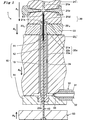
- FIG. 2 is a schematic cross-sectional front view showing a state before use of the injection mold of the present invention and showing a state before the injection needle is pushed up.
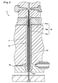
- FIG. 2 is a schematic cross-sectional front view showing a state where the injection mold of the present invention is being used and showing a state in which a resin is injected by pushing up an injection needle.
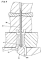
- It is a fragmentary sectional front view which expands and shows the principal part of the metal mold
- FIG. 1 shows a schematic sectional front view of an embodiment of an injection mold 1 of the present invention.
- the injection mold 1 is for molding a syringe 60 with a needle (see FIG. 4A) in which an injection needle 61 is fixed to an outer cylinder 62.
- the injection mold 1 includes a core pin 13 that forms an inner surface of an outer cylinder 62 of a syringe 60 with a needle, a fixing plate 14 to which a pin proximal end of the core pin 13 is fitted, and an injection needle 61 that is a metal cylindrical needle tube.
- the male mold 10 having a through hole 12 for inserting the core pin 13 from the tip end of the core pin 13, the support rod 40 inserted into the through hole 12 from the pin proximal end side of the core pin 13, and the female mold opening 23b.
- a female mold 20 having a recess 24 that forms the outer surface of the outer cylinder 62, and a resin injection gate 33 for injecting resin into the cavity space 20a formed by the male mold 10 and the female mold 20 are provided.
- the support bar 40 can contact the needle proximal end portion of the injection needle 61 inserted into the through hole 12 and push up the injection needle 61.
- FIG. 1 shows a state before the support bar 40 pushes up the injection needle 61.
- the core pin 13 of the male die 10 has a cylindrical shape between the pin tip and the pin base end, the diameter thereof is uniform, the pin tip is substantially conical, and has a raised portion 11 at the tip. However, the base end portion is formed in a cylindrical shape with an enlarged diameter. In the vicinity of the pin tip of the core pin 13, the raised portion 11 is steeper than the substantially conical hem.
- a through hole 12 penetrating from the tip of the pin to the base end of the pin is provided on the central axis of the core pin 13. In order to facilitate insertion of the injection needle 61, the inner diameter of the through hole 12 is slightly larger than the outer diameter of the injection needle 61 so as to have play.
- the outer diameter of the raised portion 11 is 1.5 mm or less, preferably 1.0 mm or less, more preferably 0.5 mm or less.
- the height of the raised part 11 is 1.5 mm or less, Preferably it is 1.0 mm or less, More preferably, it is 0.5 mm or less.
- the raised part 11 is so preferable that it is small, and does not need to exist.
- the through hole 12 is cylindrical and has an inner diameter slightly larger than the outer diameter of the injection needle 61. Due to the difference in diameter between the inner diameter of the through hole 12 and the outer diameter of the injection needle 61, a slight play is provided so that the injection needle 61 can be inserted and pushed up. Thereby, the through hole 12 does not damage the side surface of the inserted injection needle 61 and does not tilt the injection needle 61.
- the fixing plate 14 has a fitting hole into which the pin base end of the core pin 13 whose diameter is expanded in a columnar shape is fitted, and the core pin 13 is fitted into the hole and vertically supported.
- the through hole 12 extends from the fitting hole of the fixed plate 14 to the bottom surface of the fixed plate 14 while having the same diameter and being coaxial.
- a support bar 40 is inserted into the through hole 12 from the pin base end of the core pin 13 through the fixing plate 14.
- the support rod 40 is supported by pushing up the injection needle 61 so that the injection needle 61 is pushed up by the tip of the support rod 40 being in contact with the injection needle 61, thereby preventing the injection needle 61 from falling off the through hole 12.
- the distal end surface of the support bar 40 is a concave surface with a recessed center so that the injection needle 61 can be supported without contacting the proximal end of the injection needle 61 as much as possible.
- the base end portion of the support rod 40 is fixed by being stabbed into a drive plate 50 that pushes up the support rod 40.
- the drive plate 50 is connected to a lift drive source (not shown). Thereby, the front end surface of the support bar 40 can be moved up and down in the through hole 12 to adjust the vertical position of the injection needle 61 inserted into the through hole 12.
- the female mold 20 is placed on the fixed plate 14 and mounted on the body forming female mold 23 for forming the body 65 and the flange 68 of the outer cylinder 62, and the body forming female mold 23.
- the body forming female mold 23 has a cavity space 20a corresponding to the body 65 of the outer cylinder 62 and the flange 68 (see FIG. 4A) between the core pin 13 penetrating the body forming female mold 23.
- a body part forming space part 23a for forming and a female mold opening part 23b for inserting the core pin 13 into the body part forming space part 23a are provided.
- the female mold opening 23 b and the body forming space 23 a are coaxial with the core pin 13.
- the tube tip portion forming female die 22 is a recess for forming a collar skirt portion 63c (see FIG. 4B) of the tube tip portion 63 of the outer tube 62 on the surface facing the body portion forming female die 23.
- a tube tip forming space 22c is provided.
- the tube tip forming space 22 c is coaxial with the core pin 13.
- the female die 22 for forming the tube tip part can be separated into left and right parts so that the head part 63a and the collar skirt part 63c (see FIG. 4B) of the tube tip part 63 formed in the head forming space part 21e can be taken out.
- the female die 22 for forming the tube tip part can be separated into left and right parts so that the head part 63a and the collar skirt part 63c (see FIG. 4B) of the tube tip part 63 formed in the head forming space part 21e can be taken out.
- left die 22 L and the right type 22 R Left die 22 L and the right type 22 R is butted symmetrically, that their divided surfaces come together, the cylindrical tip formed space portion 22c is formed.
- the needle holding female mold 21 holds the head forming space 21 e for forming the head 63 a of the tube tip 63 and the injection needle 61 on the side facing the tube tip forming female die 22. And a needle holding hole 21a.
- the injection needle holding hole 21a and the through hole 12 are coaxial.
- the periphery of the head forming space 21e is larger than the tube tip forming space 22c.
- a convex portion 21c is provided at the center of the head forming space portion 21e so as to surround the opening portion of the injection needle holding hole.
- a portion that is an edge of the opening of the injection needle holding hole of the convex portion 21c is chamfered, and an inclined portion 21d that slightly widens the opening of the injection needle holding hole is formed.
- the surface of the convex portion 21c and the inner surface of the head forming space portion 21e are subjected to a satin finish or a rough surface so as to be easily punched.
- the needle holding female die 21 is provided with a pair of clamping portions 21b for clamping the injection needle 61.
- the pair of clamping portions 21b are arranged so that the pushed-up injection needle 61 can be fixed by being clamped in the injection needle holding hole 21a so that the central axis of the injection needle 61 and the central axis of the core pin 13 are substantially coincided with each other. In the direction perpendicular to the direction, the needle holding female mold 21 is inserted and removed.
- a concave portion 24 is formed which includes a body portion forming space portion 23a, a tube tip forming space portion 22c, and a head portion forming space portion 21e.
- the recess 24 corresponds to the outer shape of the outer cylinder 62 in order to form the outer surface of the outer cylinder 62.
- the core pin 13 is inserted into the recess 24 so as to be coaxial.
- a cavity space 20 a that molds the outer cylinder 62 is formed by the recess 24, the core pin 13 and the fixing plate 14.
- the cavity space 20a forms a gap that forms the body 65, the tube tip 63, and the flange 68 of the outer tube 62 of the syringe 60 with the needle with the desired thickness.
- the resin injection gate 33 is for injecting resin into the cavity space 20a, and only one is provided in the body forming female mold 23 so as to form a side surface of one end of the flange 68.
- a resin injection nozzle 30 that guides and injects the hot-melt thermoplastic resin into the cavity space 20 a is connected to the resin injection gate 33.
- the resin injection nozzle 30 has a runner portion 31 through which a thermoplastic resin melted in a tubular shape is flowed.
- the runner portion 31 communicates with the cavity space 20a that forms the flange 68 so that the cavity space 20a can be filled with resin via the resin injection gate 33.
- a heater 32 is provided around the runner portion 31 to maintain the molten state of the resin flowing into the runner portion 31.
- the barrel forming female mold 23 is connected to the fixing plate 14, the tube tip forming female mold 22 is connected to the barrel forming female mold 23, and the needle holding female mold 21 is then used to form the tube tip forming female mold.
- 22 is connected to a single raising / lowering drive source (not shown) that interlocks the respective molds 21, 22, and 23 so that the female molds 20 are connected in order to abut against each other and perform injection molding.
- -It connects with the several raising / lowering drive source (not shown) which each operates 22 * 23.
- the drive plate 50 may be connected to a lifting drive source (not shown) that operates in conjunction with or individually with the molds 21, 22, and 23 so that the drive plate 50 contacts the fixed plate 14.
- the female mold 20 is connected to an elevating drive source so as to separate the female mold 20 in reverse order to take out the syringe 60 with the needle after injection molding.
- the tip of the core pin 13 may be substantially hemispherical or semipolyhedral.
- the outer shape of the raised portion 11 may be a substantially truncated cone shape, a substantially semispherical shape, or a substantially polygonal frustum shape.
- the needle holding female mold 21 and / or the body forming female mold 23 may be a pair of molds facing each other so as to be openable and closable in a direction orthogonal to the axial direction of the core pin 13.
- the needle holding female die 21, the tube tip forming female die 22, the body forming female die 23, and the drive plate 50 are driven on the basis of the stationary stationary plate 14 is relatively shown, Any of them may be stationary or all may be movable as long as they operate similarly.
- the syringe 60 with a needle is manufactured as follows.
- Needle holder forming female mold 22 is Tsukiawashi the left die 22 L and the right mold 22 R, are formed.
- the support bar 40 is pushed up so that the needle tip of the injection needle 61 protrudes upward from the through hole 12 while the injection needle 61 is sufficiently inserted into the through hole 12.
- the injection needle 61 is inserted into the through hole 12 from the proximal end of the needle, and the injection needle 61 is pushed up and supported by the support rod 40.
- the body forming female die 23 is arranged above the needle tip of the injection needle 61 so that the body forming space 23a and the core pin 13 are coaxial. Core pin 13 and remains to match the central axis of the female mold openings 20, and the fixing plate 14 until the abutment to move the body portion forming the female mold 23 in the closing direction A 4. Thereby, the core pin 13 is inserted into the trunk portion forming space 23a.
- the tube tip forming female die 22 is arranged above the needle tip of the injection needle 61 so that the tube tip forming space 22c and the core pin 13 are coaxial. While it matches their central axis, until contact with the body portion forming the female mold 23 to move the needle holder forming the female mold 22 in the closing direction A 3.
- the needle holding female die 21 is arranged above the needle tip of the injection needle 61 so that the injection needle holding hole 21a and the core pin 13 are coaxial. While match their central axes, while inserting the needle 61 into the needle holding hole 21a, until contact with the cylindrical tip portion forming a female mold 22, the needle holding female die 21 in a closing direction A 2 move. Thereby, the needle tip side of the injection needle 61 is inserted into the injection needle holding hole 21a. At this time, the needle tip of the injection needle 61 is located below the clamping portion 21b.
- a concave portion 24 including a body portion forming space portion 23 a, a tube tip forming space portion 22 c, and a head forming space portion 21 e is formed, and between the female die 20 and the male die 10.
- a cavity space 20a is formed. Since the injection needle 61 is inserted deeply into the core pin 13, tilting is suppressed in the process of forming the cavity space 20a.
- the needle holding hole 21a, the tube tip forming space portion 22c, the body forming space portion 23a, the head forming space portion 21e, and the core pin 13 are driven while being kept coaxial.
- the plate 50 moves in the closing direction a 5 until it abuts against the fixed plate 14.
- the support rod 40 connected to the drive plate 50 moves up and pushes the needle proximal end portion of the injection needle 61 to the vicinity of the distal end of the raised portion 11.
- the needle tip of the injection needle 61 moves upward from the clamping part 21b.
- the needle base end portion of the injection needle 61 is pushed up to the end of the raised portion 11 as much as possible to the extent that the resin can be prevented from flowing into the needle hole from the needle base end portion of the injection needle 61.
- the injection needle 61 is pushed up in the injection needle holding hole 21 a and is held with its central axis coinciding with the central axis of the core pin 13. Therefore, in the injection mold 1, the raised portion 11 can be made as small as possible (see FIG. 3), and the recessed portion 64 on the inner wall of the outer cylinder 62 of the syringe 60 with a needle formed by being transferred from the raised portion 11. Extremely small.
- this hollow part 64 can become a dead space, in order to suppress tilting of the injection needle 61 as in the prior art, it is several minutes more than what is molded while being inserted deeply into the core pin 13 (see FIG. 6). It can be reduced to about 1 to 1/10.
- the injection needle 61 can be fixed in a state where it and the core pin 13 are substantially coaxial.
- the molten resin is injected into the cavity space 20a from the resin injection gate 33 through the runner portion 31, and injection molding is performed to mold the syringe 60 with a needle. .
- the cavity space 20a corresponding to the flange 68, the body portion 65, and the tube tip portion 63 of the syringe 60 with a needle is sequentially filled with the hot-melted thermoplastic resin by injection molding. If the resin is continuously filled for a while, the cavity space 20a corresponding to the head portion 63a of the tube tip portion 63 is completely filled. The resin that has been thermally melted in the cavity space 20a is cooled and solidified. At this time, since the needle proximal end of the injection needle 61 held at a predetermined position is slightly within the raised portion 11, the resin can be prevented from entering the needle hole from the proximal end side. The resin is solidified so as to surround substantially half of the injection needle 61 in the tube tip forming space 22c.
- the injection needle 61 is securely fixed and held on the outer cylinder 62 without the needle hole being blocked.
- the core pin 13 disposed in the cavity space 20a forms an inner space 66 of the outer cylinder 62 that fills the medicine and an opening 67 that injects the medicine into the inner space 66, and is formed by the recess 24 of the cavity space 20a.
- the outer wall of the outer cylinder 62 is formed (see FIG. 4A).
- the clamping portions 21b open and move in the opposite direction of the closing direction A 1, permits moving the needle holding female mold 21. Then, move the needle holding female mold 21 in the opposite direction of the closing direction A 2. Furthermore, after decomposing the needle holder forming female die 22 to the left die 22L and the right mold 22 R, it moves in the opposite direction of the closing direction A 3. Then, by moving the body portion forming the female mold 23 in the opposite direction of the closing direction A 4, it performs mold opening of the injection mold 1. The formed syringe 60 with a needle is extracted from the core pin 13 and taken out. If necessary, burrs generated on the flange 68 for the resin injection gate 33 are removed.
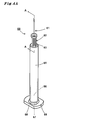
- the needle-equipped syringe 60 of the present invention thus manufactured is formed by an outer cylinder 62 made of resin and an injection needle 61 integrally joined to the cylinder tip 63 as shown in FIG. 4A.
- the outer cylinder 62 has a cylindrical shape and has an inner space 66 filled with a medicine, a cylinder tip part 63 provided at the distal end, and a body part 65 made of a peripheral wall that continues to the periphery and extends toward the proximal end. And an opening 67 provided at the base end.
- the opening 67 has a flange 68 that extends perpendicularly to the axis of the body 65 and outwards.
- the flange 68 has only one gate mark 69 formed on the resin injection gate 33 when the needle-equipped syringe 60 is molded on the outer surface.
- the injection needle 61 is penetrated through the tube tip 63.
- the tube tip portion 63 has a substantially truncated cone-shaped recess portion 64 transferred from the raised portion 11 on the inner surface thereof.
- the outer diameter of the hollow portion 64 is 1.5 mm or less, preferably 1.0 mm or less, more preferably 0.5 mm or less. Moreover, the depth of the hollow part 64 is 1.5 mm or less, Preferably it is 1.0 mm or less, More preferably, it is 0.5 mm or less. It should be noted that the smaller the recess, the better.
- the needle proximal end of the injection needle 61 slightly protrudes from the recess 64 to the inner space 66 of the body 65.
- the length of the needle proximal end protruding to the inner space 66 is 1.5 mm or less, preferably 1.0 mm or less, more preferably 0.5 mm or less, and further preferably 0 mm.
- the hollow part 64 can make the dead space formed between the base end of the injection needle 61 and the front-end
- the injection needle 61 is held in a state in which the portion from the center portion to the blade tip portion at the tip protrudes from the tube tip portion 63 to the tip side.
- the axis of the held injection needle 61 is substantially parallel to the axis of the outer peripheral surface of the body portion 65 because the axis is not inclined at all or is hardly inclined.
- substantially parallel means that the axis of the injection needle 61 is completely parallel to the axis of the outer peripheral surface of the barrel 65 of the outer cylinder 62 or the central axis of the injection needle 61 with respect to the central axis of the outer peripheral surface of the barrel 65.
- the inclination of the angle is 2 degrees or less.
- the tube tip part 63 has a collar skirt part 63c and a head part 63a.
- An annular head portion 63a having a somewhat enlarged diameter is mounted on the heel skirt portion 63c, and has an annular slope 63b penetrated by the injection needle 61 while the center of the annular recess rises conically. .
- the hollow portion 64 may be formed in a substantially truncated cone shape, a substantially semispherical shape, or a substantially polygonal frustum shape according to the shape of the raised portion 11.
- the center of the head 63a may be raised in a dome shape around the injection needle 61 in accordance with the shape of the inclined portion 21d.
- the shape of the collar skirt portion 63c of the tube tip portion 63 may be a polygonal column shape such as a quadrangular column shape, a hexagonal column shape, or a column shape as long as the tube tip portion 63 can secure the strength for holding the injection needle 61.
- the resin constituting the outer cylinder 62 is selected from the viewpoints of chemical resistance, heat resistance, gas / bacteria barrier properties, safety to living bodies, transparency, and the like.
- a thermoplastic resin exemplified by polyolefin resin such as polyethylene, polypropylene, cycloolefin polymer; polystyrene; polycarbonate; polyester such as polyethylene terephthalate;
- polyolefin resin such as polyethylene, polypropylene, cycloolefin polymer; polystyrene; polycarbonate; polyester such as polyethylene terephthalate
- a cyclic olefin homopolymer or a cyclic olefin copolymer which is a resin that is transparent so that the chemical liquid accommodated therein can be visually confirmed from the outside and has little interaction with the chemical liquid.
- the material of the injection needle 61 is a material that can withstand injection molding, and is selected from the viewpoints of chemical resistance, heat resistance, gas / bacteria barrier properties, safety to the living body, and the like.
- stainless steel and nickel-free stainless steel can be mentioned, but stainless steel that is relatively easy to form and inexpensive is preferable.
- the position where the needle base end portion of the injection needle 61 is held by the tube tip portion 63 does not have to be at the center of the tube tip portion 63 and may be somewhat shifted in the radial direction with respect to the body portion 65. Further, the direction of the injection needle 61 may be adjusted after the blade surface is detected by a sensor so that the blade surface of the injection needle 61 faces the flange 68, and then inserted into the through hole 12.
- FIG. 5 shows a schematic cross-sectional front view of another form of the injection mold 1.
- the injection mold 1 is a core pin 13 having a cooling mechanism inside instead of the core pin 13 of FIG.
- the cooling mechanism cools the hot-melted thermoplastic resin injected from the resin injection gate 33 by heat conduction.
- the cooling mechanism is a water-cooling mechanism that exchanges heat by flowing cooling water.
- the cooling mechanism has a groove through which cooling water flows inside the core pin 13.
- the core pin 13 is hollowed in a cylindrical shape, and a cylindrical core portion 15 is fitted and screwed into the core pin 13.
- the core pin 13 is provided with a through hole 12 penetrating from the tip end of the pin to the base end of the pin on the central axis together with the core portion 15.
- the core portion 15 is provided with a pair of vertical grooves 15b on the side surface of the core rod 15c from the lower end to the upper end in a line symmetry, and a semi-annular horizontal groove 15a that connects each vertical groove 15b with the edge of the upper end.
- the vertical groove 15b is connected at the lower end to the pipe 14a opened in the fixed plate 14 so that the cooling water flows from one vertical groove 15b to the other vertical groove 15b through the horizontal groove 15a.
- the cooling water flowing through the horizontal grooves 15a and the vertical grooves 15b is caused to flow in the flow path in the core pin 13 to cool the hot-melt hot-melt resin injected into the cavity space 20a in the injection mold 1 and Solidify.
- the cooling mechanism may be a heat conductive metal rod cooled by a refrigerant.
- the method of manufacturing a syringe with a needle using the injection mold of the present invention can be used to manufacture a syringe with a needle that has little dead space and the injection needle is not inclined with respect to the outer cylinder.
- the needled syringe can be used for subcutaneous injection of biologics such as vaccines.
- injection mold 10: male mold, 11: raised portion, 12: through hole, 13: core pin, 14: fixing plate, 14a: pipe, 15: core portion, 15a: transverse groove, 15b: longitudinal groove 15c: core rod, 16: insertion part, 20: female mold, 20a: cavity space, 21: female mold for needle holding, 21a: injection needle holding hole, 21b: clamping part, 21c: convex part, 21d: inclined portion, 21e: head forming space, 22: cylindrical tip portion forming the female mold, 22 L: left die, 22 R: right type 22c: cylindrical tip forming space, 23: body portion forming the female mold, 23a: body part forming space part, 23b: female mold opening, 24: recessed part, 30: resin injection nozzle, 31: runner part, 32: heater, 33: resin injection gate, 40: support rod, 50: drive plate , 60: syringe with needle, 61: injection needle, 62: outer cylinder, 63 Needle holder, 63a: Head,
Landscapes
- Health & Medical Sciences (AREA)
- Engineering & Computer Science (AREA)
- Hematology (AREA)
- Life Sciences & Earth Sciences (AREA)
- Vascular Medicine (AREA)
- Anesthesiology (AREA)
- Biomedical Technology (AREA)
- Heart & Thoracic Surgery (AREA)
- Veterinary Medicine (AREA)
- Public Health (AREA)
- Animal Behavior & Ethology (AREA)
- General Health & Medical Sciences (AREA)
- Mechanical Engineering (AREA)
- Manufacturing & Machinery (AREA)
- Infusion, Injection, And Reservoir Apparatuses (AREA)
- Moulds For Moulding Plastics Or The Like (AREA)
- Injection Moulding Of Plastics Or The Like (AREA)
Abstract
Priority Applications (3)
| Application Number | Priority Date | Filing Date | Title |
|---|---|---|---|
| JP2016511567A JP6510492B2 (ja) | 2014-03-31 | 2015-03-24 | 射出成型用金型 |
| EP15772956.7A EP3127677A4 (fr) | 2014-03-31 | 2015-03-24 | Moule de moulage par injection |
| US15/280,568 US10493216B2 (en) | 2014-03-31 | 2016-09-29 | Method for producing a needle-equipped syringe |
Applications Claiming Priority (2)
| Application Number | Priority Date | Filing Date | Title |
|---|---|---|---|
| JP2014-071911 | 2014-03-31 | ||
| JP2014071911 | 2014-03-31 |
Related Child Applications (1)
| Application Number | Title | Priority Date | Filing Date |
|---|---|---|---|
| US15/280,568 Continuation US10493216B2 (en) | 2014-03-31 | 2016-09-29 | Method for producing a needle-equipped syringe |
Publications (1)
| Publication Number | Publication Date |
|---|---|
| WO2015151936A1 true WO2015151936A1 (fr) | 2015-10-08 |
Family
ID=54240263
Family Applications (1)
| Application Number | Title | Priority Date | Filing Date |
|---|---|---|---|
| PCT/JP2015/058948 WO2015151936A1 (fr) | 2014-03-31 | 2015-03-24 | Moule de moulage par injection |
Country Status (4)
| Country | Link |
|---|---|
| US (1) | US10493216B2 (fr) |
| EP (1) | EP3127677A4 (fr) |
| JP (2) | JP6510492B2 (fr) |
| WO (1) | WO2015151936A1 (fr) |
Cited By (7)
| Publication number | Priority date | Publication date | Assignee | Title |
|---|---|---|---|---|
| JP2017154280A (ja) * | 2016-02-29 | 2017-09-07 | 住友理工株式会社 | 曲管状樹脂チューブの製造方法 |
| JP2017169896A (ja) * | 2016-03-24 | 2017-09-28 | テルモ株式会社 | 医療用針及びその製造方法 |
| DE102016107131A1 (de) * | 2016-04-18 | 2017-10-19 | Gerresheimer Regensburg Gmbh | Werkzeug zum Herstellen einer Injektionsvorrichtung und Verfahren zum Herstellen einer Injektionsvorrichtung |
| DE102016118768A1 (de) * | 2016-10-04 | 2018-04-05 | Gerresheimer Regensburg Gmbh | Verfahren zum Herstellen einer Spritze mit einem integrierten Verschlusselement |
| CN109249592A (zh) * | 2017-07-13 | 2019-01-22 | 格雷斯海姆里根斯堡有限公司 | 用于制造注塑件的注塑模具和用于制造注塑件的方法 |
| CN114344609A (zh) * | 2015-10-09 | 2022-04-15 | 维斯特医药服务以色列有限公司 | 筒和制造筒的方法 |
| JP7542177B2 (ja) | 2020-08-13 | 2024-08-30 | 株式会社トップ | 針付きシリンジの製造方法 |
Families Citing this family (3)
| Publication number | Priority date | Publication date | Assignee | Title |
|---|---|---|---|---|
| EP3109026B1 (fr) * | 2015-06-23 | 2018-11-28 | Gerresheimer Regensburg GmbH | Dispositif de fabrication de pièces en matière plastique ayant des inserts |
| CN107379422A (zh) * | 2017-09-11 | 2017-11-24 | 格林精密部件(苏州)有限公司 | 一种长轴工件注塑模具 |
| DE102018121835A1 (de) * | 2018-09-07 | 2020-03-12 | Gerresheimer Regensburg Gmbh | Verfahren und Vorrichtung zur Herstellung eines hohlförmigen Spritzgussteils |
Citations (3)
| Publication number | Priority date | Publication date | Assignee | Title |
|---|---|---|---|---|
| JPH0966104A (ja) * | 1995-09-01 | 1997-03-11 | Koki Eng:Kk | 針一体型シリンジ |
| WO2008139982A1 (fr) * | 2007-04-26 | 2008-11-20 | Daikyo Seiko, Ltd. | Corps de seringue avec aiguille d'injection, seringue avec aiguille d'injection, matrice pour moulage d'un corps de seringue avec aiguille d'injection et procédé de moulage d'un corps de seringue avec aiguille d'injection |
| JP2011510836A (ja) * | 2008-01-15 | 2011-04-07 | ウエスト・ファーマシューティカル・サービシーズ・インコーポレイテッド | コレット機構およびカニューレを注射筒に成形する方法 |
Family Cites Families (11)
| Publication number | Priority date | Publication date | Assignee | Title |
|---|---|---|---|---|
| US3330004A (en) * | 1963-11-04 | 1967-07-11 | Nosco Plastics | Hypodermic syringe |
| US4956143A (en) * | 1981-09-16 | 1990-09-11 | Taut, Inc. | Method and apparatus for the multi-unit production of thin-walled tubular products utilizing an injection molding technique |
| US5380301A (en) * | 1992-07-10 | 1995-01-10 | Sherwood Medical Company | Catheter/hub strain relief and method of manufacture thereof |
| US7842217B2 (en) * | 2007-03-28 | 2010-11-30 | Benlan, Inc. | Enteral-only syringe and method of manufacturing same |
| US8721603B2 (en) * | 2008-01-15 | 2014-05-13 | West Pharmaceutical Services, Inc. | Syringe with co-molded hub and cannula |
| US20110254202A1 (en) * | 2008-12-24 | 2011-10-20 | Ssb Technology Pty Ltd | Moulding cannulae and small deep holes |
| EP2623144B1 (fr) * | 2010-09-29 | 2017-02-22 | Terumo Kabushiki Kaisha | Seringue pourvue d'une aiguille |
| WO2012150897A1 (fr) * | 2011-05-03 | 2012-11-08 | Shl Group Ab | Ensemble moule et procédé de fabrication d'un contenant de seringue |
| JP2013070892A (ja) * | 2011-09-29 | 2013-04-22 | Terumo Corp | 針付きシリンジの製造方法 |
| DE102011120403A1 (de) * | 2011-12-03 | 2013-06-06 | Zahoransky Ag | Vorrichtung zum Anspritzen eines Kunststoff-Formteils an ein Funktionsteil zur Bildung eines Mehrkomponeten-Teils |
| CH706504A1 (de) * | 2012-05-14 | 2013-11-15 | Schoettli Ag | Verfahren zur Herstellung eines Spritzenzylinders für medizinische Zwecke sowie eine Vorrichtung zur Durchführung des Verfahrens. |
-
2015
- 2015-03-24 WO PCT/JP2015/058948 patent/WO2015151936A1/fr active Application Filing
- 2015-03-24 EP EP15772956.7A patent/EP3127677A4/fr not_active Withdrawn
- 2015-03-24 JP JP2016511567A patent/JP6510492B2/ja active Active
-
2016
- 2016-09-29 US US15/280,568 patent/US10493216B2/en active Active
-
2019
- 2019-04-03 JP JP2019071417A patent/JP6768869B2/ja active Active
Patent Citations (3)
| Publication number | Priority date | Publication date | Assignee | Title |
|---|---|---|---|---|
| JPH0966104A (ja) * | 1995-09-01 | 1997-03-11 | Koki Eng:Kk | 針一体型シリンジ |
| WO2008139982A1 (fr) * | 2007-04-26 | 2008-11-20 | Daikyo Seiko, Ltd. | Corps de seringue avec aiguille d'injection, seringue avec aiguille d'injection, matrice pour moulage d'un corps de seringue avec aiguille d'injection et procédé de moulage d'un corps de seringue avec aiguille d'injection |
| JP2011510836A (ja) * | 2008-01-15 | 2011-04-07 | ウエスト・ファーマシューティカル・サービシーズ・インコーポレイテッド | コレット機構およびカニューレを注射筒に成形する方法 |
Non-Patent Citations (1)
| Title |
|---|
| See also references of EP3127677A4 * |
Cited By (12)
| Publication number | Priority date | Publication date | Assignee | Title |
|---|---|---|---|---|
| CN114344609A (zh) * | 2015-10-09 | 2022-04-15 | 维斯特医药服务以色列有限公司 | 筒和制造筒的方法 |
| JP2017154280A (ja) * | 2016-02-29 | 2017-09-07 | 住友理工株式会社 | 曲管状樹脂チューブの製造方法 |
| JP2017169896A (ja) * | 2016-03-24 | 2017-09-28 | テルモ株式会社 | 医療用針及びその製造方法 |
| DE102016107131A1 (de) * | 2016-04-18 | 2017-10-19 | Gerresheimer Regensburg Gmbh | Werkzeug zum Herstellen einer Injektionsvorrichtung und Verfahren zum Herstellen einer Injektionsvorrichtung |
| DE102016107131B4 (de) * | 2016-04-18 | 2020-02-13 | Gerresheimer Regensburg Gmbh | Werkzeug zum Herstellen einer Injektionsvorrichtung und Verfahren zum Herstellen einer Injektionsvorrichtung |
| US10603827B2 (en) | 2016-04-18 | 2020-03-31 | Gerresheimer Regensburg Gmbh | Tool for producing an injection device and method for producing an injection device |
| DE102016118768A1 (de) * | 2016-10-04 | 2018-04-05 | Gerresheimer Regensburg Gmbh | Verfahren zum Herstellen einer Spritze mit einem integrierten Verschlusselement |
| DE102016118768B4 (de) | 2016-10-04 | 2022-05-05 | Gerresheimer Regensburg Gmbh | Verfahren zum Herstellen einer Spritze mit einem integrierten Verschlusselement |
| CN109249592A (zh) * | 2017-07-13 | 2019-01-22 | 格雷斯海姆里根斯堡有限公司 | 用于制造注塑件的注塑模具和用于制造注塑件的方法 |
| CN109249592B (zh) * | 2017-07-13 | 2021-03-23 | 格雷斯海姆里根斯堡有限公司 | 用于制造注塑件的注塑模具和用于制造注塑件的方法 |
| US10994459B2 (en) | 2017-07-13 | 2021-05-04 | Gerresheimer Regensburg Gmbh | Injection mold for manufacturing an injection-molded component and method for manufacturing an injection-molded component |
| JP7542177B2 (ja) | 2020-08-13 | 2024-08-30 | 株式会社トップ | 針付きシリンジの製造方法 |
Also Published As
| Publication number | Publication date |
|---|---|
| JP6768869B2 (ja) | 2020-10-14 |
| JPWO2015151936A1 (ja) | 2017-04-13 |
| EP3127677A1 (fr) | 2017-02-08 |
| JP2019111832A (ja) | 2019-07-11 |
| US10493216B2 (en) | 2019-12-03 |
| EP3127677A4 (fr) | 2017-12-13 |
| US20170014580A1 (en) | 2017-01-19 |
| JP6510492B2 (ja) | 2019-05-08 |
Similar Documents
| Publication | Publication Date | Title |
|---|---|---|
| WO2015151936A1 (fr) | Moule de moulage par injection | |
| JP6298822B2 (ja) | 針付きシリンジ及びその射出成型用金型 | |
| EP3375427B1 (fr) | Mélangeur de médicament, élément dur à deux orifices, et poche d'infusion souple | |
| US9919094B2 (en) | Cartridge set for manufacturing syringe and method for manufacturing dual-chamber type combined container-syringe | |
| EP2448745B1 (fr) | Procédé de production et d'assemblage de séringues médicales | |
| JP4818752B2 (ja) | シリンジ用外筒の射出成形用金型、シリンジ用外筒の製造方法、シリンジ用外筒およびプレフィルドシリンジ | |
| JP6118400B2 (ja) | 薬液注射器 | |
| JP2004505733A (ja) | 改良された使い捨て注射装置 | |
| US9345846B1 (en) | Molding apparatus, method and syringe produced using same | |
| US11850778B2 (en) | Method for producing a syringe with an integrated closure element | |
| WO2017135060A1 (fr) | Micro-aiguille | |
| JP2012527913A (ja) | 凍結乾燥、貯蔵、再構成のための二重チャンバーシリンダー−ピストンユニット及び注射器用の注射液の適用及びシリンダー−ピストンユニットの充填方法 | |
| US10933194B2 (en) | Syringe for and method of delivering a volume of solution | |
| EP2440384B1 (fr) | Procede de fabrication de seringues | |
| WO2014178242A1 (fr) | Cylindre extérieur à aiguille et son procédé de production | |
| JP2019188119A (ja) | 移注部材及びその製造方法 | |
| KR102563640B1 (ko) | 약물 주입장치용 인젝션 팁 및 이 인젝션 팁의 제조방법 | |
| JP6889921B2 (ja) | シリンジ用プランジャー、その製造方法及び医療用シリンジ | |
| KR20180126996A (ko) | 약액을 장전하는 방식의 주사기 틀 및 약병 | |
| CN113713213A (zh) | 一种整形外科用一次性玻尿酸注射器 | |
| JP2002283401A (ja) | 金型装置及びシート材の除去方法 | |
| CA2804130A1 (fr) | Seringue a blocage automatique |
Legal Events
| Date | Code | Title | Description |
|---|---|---|---|
| 121 | Ep: the epo has been informed by wipo that ep was designated in this application |
Ref document number: 15772956 Country of ref document: EP Kind code of ref document: A1 |
|
| ENP | Entry into the national phase |
Ref document number: 2016511567 Country of ref document: JP Kind code of ref document: A |
|
| NENP | Non-entry into the national phase |
Ref country code: DE |
|
| REEP | Request for entry into the european phase |
Ref document number: 2015772956 Country of ref document: EP |
|
| WWE | Wipo information: entry into national phase |
Ref document number: 2015772956 Country of ref document: EP |