WO2015151936A1 - Injection molding mold - Google Patents

Injection molding mold Download PDF

Info

Publication number
WO2015151936A1
WO2015151936A1 PCT/JP2015/058948 JP2015058948W WO2015151936A1 WO 2015151936 A1 WO2015151936 A1 WO 2015151936A1 JP 2015058948 W JP2015058948 W JP 2015058948W WO 2015151936 A1 WO2015151936 A1 WO 2015151936A1
Authority
WO
WIPO (PCT)
Prior art keywords
needle
injection
pin
injection needle
tip
Prior art date
Application number
PCT/JP2015/058948
Other languages
French (fr)
Japanese (ja)
Inventor
秀一 大西
Original Assignee
テルモ株式会社
Priority date (The priority date is an assumption and is not a legal conclusion. Google has not performed a legal analysis and makes no representation as to the accuracy of the date listed.)
Filing date
Publication date
Application filed by テルモ株式会社 filed Critical テルモ株式会社
Priority to JP2016511567A priority Critical patent/JP6510492B2/en
Priority to EP15772956.7A priority patent/EP3127677A4/en
Publication of WO2015151936A1 publication Critical patent/WO2015151936A1/en
Priority to US15/280,568 priority patent/US10493216B2/en

Links

Images

Classifications

    • AHUMAN NECESSITIES
    • A61MEDICAL OR VETERINARY SCIENCE; HYGIENE
    • A61MDEVICES FOR INTRODUCING MEDIA INTO, OR ONTO, THE BODY; DEVICES FOR TRANSDUCING BODY MEDIA OR FOR TAKING MEDIA FROM THE BODY; DEVICES FOR PRODUCING OR ENDING SLEEP OR STUPOR
    • A61M5/00Devices for bringing media into the body in a subcutaneous, intra-vascular or intramuscular way; Accessories therefor, e.g. filling or cleaning devices, arm-rests
    • A61M5/178Syringes
    • A61M5/31Details
    • A61M5/32Needles; Details of needles pertaining to their connection with syringe or hub; Accessories for bringing the needle into, or holding the needle on, the body; Devices for protection of needles
    • A61M5/34Constructions for connecting the needle, e.g. to syringe nozzle or needle hub
    • AHUMAN NECESSITIES
    • A61MEDICAL OR VETERINARY SCIENCE; HYGIENE
    • A61MDEVICES FOR INTRODUCING MEDIA INTO, OR ONTO, THE BODY; DEVICES FOR TRANSDUCING BODY MEDIA OR FOR TAKING MEDIA FROM THE BODY; DEVICES FOR PRODUCING OR ENDING SLEEP OR STUPOR
    • A61M5/00Devices for bringing media into the body in a subcutaneous, intra-vascular or intramuscular way; Accessories therefor, e.g. filling or cleaning devices, arm-rests
    • A61M5/178Syringes
    • A61M5/31Details
    • A61M5/3129Syringe barrels
    • BPERFORMING OPERATIONS; TRANSPORTING
    • B29WORKING OF PLASTICS; WORKING OF SUBSTANCES IN A PLASTIC STATE IN GENERAL
    • B29CSHAPING OR JOINING OF PLASTICS; SHAPING OF MATERIAL IN A PLASTIC STATE, NOT OTHERWISE PROVIDED FOR; AFTER-TREATMENT OF THE SHAPED PRODUCTS, e.g. REPAIRING
    • B29C45/00Injection moulding, i.e. forcing the required volume of moulding material through a nozzle into a closed mould; Apparatus therefor
    • B29C45/14Injection moulding, i.e. forcing the required volume of moulding material through a nozzle into a closed mould; Apparatus therefor incorporating preformed parts or layers, e.g. injection moulding around inserts or for coating articles
    • B29C45/14065Positioning or centering articles in the mould
    • AHUMAN NECESSITIES
    • A61MEDICAL OR VETERINARY SCIENCE; HYGIENE
    • A61MDEVICES FOR INTRODUCING MEDIA INTO, OR ONTO, THE BODY; DEVICES FOR TRANSDUCING BODY MEDIA OR FOR TAKING MEDIA FROM THE BODY; DEVICES FOR PRODUCING OR ENDING SLEEP OR STUPOR
    • A61M2207/00Methods of manufacture, assembly or production
    • AHUMAN NECESSITIES
    • A61MEDICAL OR VETERINARY SCIENCE; HYGIENE
    • A61MDEVICES FOR INTRODUCING MEDIA INTO, OR ONTO, THE BODY; DEVICES FOR TRANSDUCING BODY MEDIA OR FOR TAKING MEDIA FROM THE BODY; DEVICES FOR PRODUCING OR ENDING SLEEP OR STUPOR
    • A61M5/00Devices for bringing media into the body in a subcutaneous, intra-vascular or intramuscular way; Accessories therefor, e.g. filling or cleaning devices, arm-rests
    • A61M5/178Syringes
    • A61M5/28Syringe ampoules or carpules, i.e. ampoules or carpules provided with a needle
    • AHUMAN NECESSITIES
    • A61MEDICAL OR VETERINARY SCIENCE; HYGIENE
    • A61MDEVICES FOR INTRODUCING MEDIA INTO, OR ONTO, THE BODY; DEVICES FOR TRANSDUCING BODY MEDIA OR FOR TAKING MEDIA FROM THE BODY; DEVICES FOR PRODUCING OR ENDING SLEEP OR STUPOR
    • A61M5/00Devices for bringing media into the body in a subcutaneous, intra-vascular or intramuscular way; Accessories therefor, e.g. filling or cleaning devices, arm-rests
    • A61M5/178Syringes
    • A61M5/31Details
    • A61M5/32Needles; Details of needles pertaining to their connection with syringe or hub; Accessories for bringing the needle into, or holding the needle on, the body; Devices for protection of needles
    • A61M5/34Constructions for connecting the needle, e.g. to syringe nozzle or needle hub
    • A61M5/343Connection of needle cannula to needle hub, or directly to syringe nozzle without a needle hub
    • BPERFORMING OPERATIONS; TRANSPORTING
    • B29WORKING OF PLASTICS; WORKING OF SUBSTANCES IN A PLASTIC STATE IN GENERAL
    • B29CSHAPING OR JOINING OF PLASTICS; SHAPING OF MATERIAL IN A PLASTIC STATE, NOT OTHERWISE PROVIDED FOR; AFTER-TREATMENT OF THE SHAPED PRODUCTS, e.g. REPAIRING
    • B29C45/00Injection moulding, i.e. forcing the required volume of moulding material through a nozzle into a closed mould; Apparatus therefor
    • B29C45/0025Preventing defects on the moulded article, e.g. weld lines, shrinkage marks
    • B29C2045/0027Gate or gate mark locations
    • BPERFORMING OPERATIONS; TRANSPORTING
    • B29WORKING OF PLASTICS; WORKING OF SUBSTANCES IN A PLASTIC STATE IN GENERAL
    • B29CSHAPING OR JOINING OF PLASTICS; SHAPING OF MATERIAL IN A PLASTIC STATE, NOT OTHERWISE PROVIDED FOR; AFTER-TREATMENT OF THE SHAPED PRODUCTS, e.g. REPAIRING
    • B29C45/00Injection moulding, i.e. forcing the required volume of moulding material through a nozzle into a closed mould; Apparatus therefor
    • B29C45/14Injection moulding, i.e. forcing the required volume of moulding material through a nozzle into a closed mould; Apparatus therefor incorporating preformed parts or layers, e.g. injection moulding around inserts or for coating articles
    • B29C45/14065Positioning or centering articles in the mould
    • B29C2045/14139Positioning or centering articles in the mould positioning inserts having a part extending into a positioning cavity outside the mould cavity
    • BPERFORMING OPERATIONS; TRANSPORTING
    • B29WORKING OF PLASTICS; WORKING OF SUBSTANCES IN A PLASTIC STATE IN GENERAL
    • B29CSHAPING OR JOINING OF PLASTICS; SHAPING OF MATERIAL IN A PLASTIC STATE, NOT OTHERWISE PROVIDED FOR; AFTER-TREATMENT OF THE SHAPED PRODUCTS, e.g. REPAIRING
    • B29C45/00Injection moulding, i.e. forcing the required volume of moulding material through a nozzle into a closed mould; Apparatus therefor
    • B29C45/14Injection moulding, i.e. forcing the required volume of moulding material through a nozzle into a closed mould; Apparatus therefor incorporating preformed parts or layers, e.g. injection moulding around inserts or for coating articles
    • B29C45/14336Coating a portion of the article, e.g. the edge of the article
    • B29C45/14418Sealing means between mould and article
    • BPERFORMING OPERATIONS; TRANSPORTING
    • B29WORKING OF PLASTICS; WORKING OF SUBSTANCES IN A PLASTIC STATE IN GENERAL
    • B29CSHAPING OR JOINING OF PLASTICS; SHAPING OF MATERIAL IN A PLASTIC STATE, NOT OTHERWISE PROVIDED FOR; AFTER-TREATMENT OF THE SHAPED PRODUCTS, e.g. REPAIRING
    • B29C45/00Injection moulding, i.e. forcing the required volume of moulding material through a nozzle into a closed mould; Apparatus therefor
    • B29C45/14Injection moulding, i.e. forcing the required volume of moulding material through a nozzle into a closed mould; Apparatus therefor incorporating preformed parts or layers, e.g. injection moulding around inserts or for coating articles
    • B29C45/14336Coating a portion of the article, e.g. the edge of the article
    • B29C45/14426Coating the end of wire-like or rod-like or cable-like or blade-like or belt-like articles
    • BPERFORMING OPERATIONS; TRANSPORTING
    • B29WORKING OF PLASTICS; WORKING OF SUBSTANCES IN A PLASTIC STATE IN GENERAL
    • B29CSHAPING OR JOINING OF PLASTICS; SHAPING OF MATERIAL IN A PLASTIC STATE, NOT OTHERWISE PROVIDED FOR; AFTER-TREATMENT OF THE SHAPED PRODUCTS, e.g. REPAIRING
    • B29C45/00Injection moulding, i.e. forcing the required volume of moulding material through a nozzle into a closed mould; Apparatus therefor
    • B29C45/14Injection moulding, i.e. forcing the required volume of moulding material through a nozzle into a closed mould; Apparatus therefor incorporating preformed parts or layers, e.g. injection moulding around inserts or for coating articles
    • B29C45/14598Coating tubular articles
    • BPERFORMING OPERATIONS; TRANSPORTING
    • B29WORKING OF PLASTICS; WORKING OF SUBSTANCES IN A PLASTIC STATE IN GENERAL
    • B29LINDEXING SCHEME ASSOCIATED WITH SUBCLASS B29C, RELATING TO PARTICULAR ARTICLES
    • B29L2031/00Other particular articles
    • B29L2031/753Medical equipment; Accessories therefor
    • B29L2031/7544Injection needles, syringes

Definitions

  • the present invention relates to an injection mold used for molding a syringe with a needle for injecting a small amount of a chemical solution subcutaneously, and a method for manufacturing a syringe with a needle using the same.
  • a syringe with a needle is a syringe in which a small-diameter injection needle is previously passed through and fixed to the end of an outer cylinder that becomes an injection cylinder.
  • a syringe with a needle is a hypodermic rather than intravenous injection because a small amount of drug solution in the outer cylinder can be quickly discharged from the injection needle by pressing strongly with a pusher fitted with a gasket at the tip and inserted in the outer cylinder. Used for. Since this syringe with a needle has an injection needle fixed to the outer cylinder, it does not require a cumbersome operation of attaching a separate injection needle base immediately before administration, and can easily and efficiently administer a drug solution. Has been.
  • the syringe with a needle was manufactured by preparing an outer cylinder having an insertion hole at the end of the cylinder, and adhering with an adhesive while inserting the injection needle into the insertion hole.
  • the dose of a biologic such as a vaccine to be injected subcutaneously is as small as about 500 ⁇ L for pain relief at the time of administration.
  • This syringe with a needle is because the bonded injection needle has a small diameter, and when a small amount of drug solution is administered, the pressing force on the pusher tends to be too high, and the injection needle may come out of the tip of the cylinder.
  • the conventional injection mold used for manufacturing the syringe with a needle has a raised portion 11 for supporting the injection needle 61 deeply inserted into the tip of the core pin 13 and supporting it independently. It comprises a male mold 10 provided and a female mold 20 for molding the outer surface of the outer cylinder. If the insertion of the injection needle 61 into the raised portion 11 is shallow, the injection needle 61 tilts in the middle of the formation of the cavity space 20a, and the central axis of the injection needle 61 of the syringe with needle molded by the subsequent resin injection is the outer cylinder. It may be inclined with respect to the central axis. Therefore, the raised portion 11 is provided to be somewhat high and thick so that the injection needle 61 can be inserted deeply.
  • a deep and wide hollow portion transferred from the raised portion 11 is formed on the inner wall of the outer end of the molded outer tube. Since the injection needle is fixed so that the proximal end portion of the needle fits in the hollow portion, the hollow portion becomes a dead space.
  • the drug solution filled in the depression reaches several tens to hundreds of ⁇ L.
  • the tip of the gasket comes into contact with the inner wall of the outer tube, and the gasket can no longer be pressed. For this reason, the chemical liquid filled in the hollow portion cannot be pushed out, and remains as it is not discharged, resulting in a waste.
  • the present invention has been made to solve the above-mentioned problems, and is for injection molding that can manufacture a syringe with a needle that can be fixed to an outer cylinder without inclining the injection needle and that can reduce the dead space that cannot discharge the filling liquid.
  • a method of manufacturing a syringe with a needle that can be manufactured easily and with a high yield by using as many molds as possible using the mold, and the mold for injection molding, and the chemical solution that is manufactured and filled can be almost exhausted. It aims at providing the syringe with a needle which can be performed.
  • An injection mold of the present invention made to achieve the above object includes a cylindrical body, a cylinder tip provided at the front end of the body, and an opening provided at the base end of the body. And an outer cylinder molded with resin, and a needle tip end part and a needle base end part, and the needle base end part side held by the cylinder tip part, the needle and the outer
  • a male die having a through hole penetrating to the proximal end of the pin and through which the needle proximal end portion of the injection needle is inserted from the distal end of the pin, a female die opening, and communicating with the female die opening
  • a female mold having
  • the injection mold is preferably one in which the lifting of the support rod is adjusted so that the distance between the tip of the pushed-up support rod and the tip of the pin is 1.5 mm at the maximum.
  • the core pin has a raised portion that surrounds the needle base end portion at the tip of the pin and prevents the resin from flowing into the injection needle.
  • the injection mold preferably has a maximum outer diameter of the raised portion of 1.5 mm and a height of the raised portion of 1.5 mm at the maximum.
  • the injection mold is preferably such that the male mold has a cooling mechanism in the core pin for cooling the resin injected from the resin injection gate by heat conduction.
  • the female mold has a holding portion for holding the injection needle in the injection needle holding hole.
  • the manufacturing method of the syringe with a needle of the present invention made to achieve the above object is provided at a cylindrical body part, a tube tip part provided at the tip of the body part, and a base end of the body part
  • An outer cylinder formed of resin having an opening, and an injection needle having a needle distal end portion and a needle proximal end portion, the needle proximal end side being held by the tube distal end portion, the injection needle and the A method for manufacturing a syringe with a needle, wherein a syringe with a needle formed integrally with an outer cylinder is molded by an injection mold, A male mold having a core pin that includes the tip of the pin and a base of the pin to form the inner surface of the outer cylinder, a through hole that penetrates from the tip of the pin to the base of the pin, a female mold opening, and the female mold A female mold having a recess communicating with the opening and forming the outer surface of the outer cylinder, and an injection needle holding hole
  • a step of preparing a support rod inserted into the through hole from the pin proximal end side, inserting the injection needle from the needle proximal end portion into the through hole from the pin distal end side, and using the support rod The step of pushing up and supporting the needle proximal end portion of the injection needle, inserting the core pin from the female mold opening to the inner space of the concave portion to form a cavity space formed by the concave portion and the core pin Step, pushing up the support rod inserted in the through hole
  • the needle proximal end is pushed up to the vicinity of the tip of the pin and the injection needle is held in the injection needle holding hole, and the resin is injected into the cavity space, and the injection needle, the outer cylinder, The process which shape
  • the manufacturing method of the syringe with a needle is to push up the support rod until the distance between the tip of the support rod and the tip of the pin becomes 1.5 mm at the maximum.
  • a protruding portion that surrounds the proximal end portion of the needle and prevents the resin from flowing into the through hole is formed at the tip of the pin, and the resin is injected into the cavity space.
  • a hollow portion corresponding to the raised portion is formed in the outer cylinder and the needle proximal end portion is accommodated in the hollow portion.
  • the manufacturing method of the syringe with a needle is preferably such that the raised portion is formed such that the outer diameter of the raised portion is 1.5 mm at the maximum and the height is 1.5 mm at the maximum.
  • a holding portion for holding the injection needle in the injection needle holding hole is provided in the female mold, and the injection needle pushed up by the support rod is pushed up is injected into the injection needle. It is preferable that it is held by the holding portion while being supported in the needle holding hole.
  • a cooling mechanism for cooling the resin injected from the resin injection gate by heat conduction is provided in the core pin, and the resin injected into the cavity is cooled by the cooling mechanism. It is preferable that the injection needle and the outer cylinder are integrally formed and then taken out after being solidified.
  • the syringe with a needle of the present invention made to achieve the above object includes a cylindrical barrel, a barrel tip provided at the distal end of the barrel, and an opening provided at the proximal end of the barrel. And an outer cylinder formed of resin and an injection needle held at the tip of the cylinder, and the injection needle and the outer cylinder are integrally formed, and with a needle that can be filled with a drug solution in the barrel It is a syringe, and a hollow portion surrounded by an inner wall of the outer tube and recessed at a distal end side is formed at a proximal end of the tube tip portion, and an outer diameter of the hollow portion is 1.5 mm at the maximum. The depth of the depression is 1.5 mm at the maximum, and the needle proximal end of the injection needle protrudes up to 1.5 mm into the depression.
  • the injection mold of the present invention was inserted into the through hole from the pin tip side by the support rod inserted from the pin base end side into the through hole penetrating from the pin tip of the core pin to the pin base end. This is for molding a syringe with a needle by pushing up at the time of resin injection while supporting the injection needle.
  • this injection mold when the cavity space is formed by the male mold and the female mold, the injection needle is inserted deeply into the through hole and supported by the support rod so that it does not tilt. For this reason, a syringe with a needle that can be fixed to the outer cylinder without tilting the injection needle and that has a small dead space can be molded.
  • the injection needle when forming the cavity space, the injection needle is supported while being inserted deeply into the through hole of the injection mold so that the injection needle is not tilted by the support rod.
  • a syringe with a needle with a small dead space can be molded efficiently, simply and with a good yield.
  • the needle proximal end portion of the injection needle hardly protrudes into the inner space of the outer cylinder, and the hollow portion of the inner wall of the cylinder tip portion surrounding the needle is extremely small, so that the dead space is reduced. As a result, the filled chemical solution can be almost exhausted. Further, this syringe with a needle has few defective products in which the central axis of the injection needle and the central axis of the barrel portion of the outer cylinder are removed, has a good yield, and is highly safe and reliable.
  • FIG. 2 is a schematic cross-sectional front view showing a state before use of the injection mold of the present invention and showing a state before the injection needle is pushed up.
  • FIG. 2 is a schematic cross-sectional front view showing a state where the injection mold of the present invention is being used and showing a state in which a resin is injected by pushing up an injection needle.
  • It is a fragmentary sectional front view which expands and shows the principal part of the metal mold
  • FIG. 1 shows a schematic sectional front view of an embodiment of an injection mold 1 of the present invention.
  • the injection mold 1 is for molding a syringe 60 with a needle (see FIG. 4A) in which an injection needle 61 is fixed to an outer cylinder 62.
  • the injection mold 1 includes a core pin 13 that forms an inner surface of an outer cylinder 62 of a syringe 60 with a needle, a fixing plate 14 to which a pin proximal end of the core pin 13 is fitted, and an injection needle 61 that is a metal cylindrical needle tube.
  • the male mold 10 having a through hole 12 for inserting the core pin 13 from the tip end of the core pin 13, the support rod 40 inserted into the through hole 12 from the pin proximal end side of the core pin 13, and the female mold opening 23b.
  • a female mold 20 having a recess 24 that forms the outer surface of the outer cylinder 62, and a resin injection gate 33 for injecting resin into the cavity space 20a formed by the male mold 10 and the female mold 20 are provided.
  • the support bar 40 can contact the needle proximal end portion of the injection needle 61 inserted into the through hole 12 and push up the injection needle 61.
  • FIG. 1 shows a state before the support bar 40 pushes up the injection needle 61.
  • the core pin 13 of the male die 10 has a cylindrical shape between the pin tip and the pin base end, the diameter thereof is uniform, the pin tip is substantially conical, and has a raised portion 11 at the tip. However, the base end portion is formed in a cylindrical shape with an enlarged diameter. In the vicinity of the pin tip of the core pin 13, the raised portion 11 is steeper than the substantially conical hem.
  • a through hole 12 penetrating from the tip of the pin to the base end of the pin is provided on the central axis of the core pin 13. In order to facilitate insertion of the injection needle 61, the inner diameter of the through hole 12 is slightly larger than the outer diameter of the injection needle 61 so as to have play.
  • the outer diameter of the raised portion 11 is 1.5 mm or less, preferably 1.0 mm or less, more preferably 0.5 mm or less.
  • the height of the raised part 11 is 1.5 mm or less, Preferably it is 1.0 mm or less, More preferably, it is 0.5 mm or less.
  • the raised part 11 is so preferable that it is small, and does not need to exist.
  • the through hole 12 is cylindrical and has an inner diameter slightly larger than the outer diameter of the injection needle 61. Due to the difference in diameter between the inner diameter of the through hole 12 and the outer diameter of the injection needle 61, a slight play is provided so that the injection needle 61 can be inserted and pushed up. Thereby, the through hole 12 does not damage the side surface of the inserted injection needle 61 and does not tilt the injection needle 61.
  • the fixing plate 14 has a fitting hole into which the pin base end of the core pin 13 whose diameter is expanded in a columnar shape is fitted, and the core pin 13 is fitted into the hole and vertically supported.
  • the through hole 12 extends from the fitting hole of the fixed plate 14 to the bottom surface of the fixed plate 14 while having the same diameter and being coaxial.
  • a support bar 40 is inserted into the through hole 12 from the pin base end of the core pin 13 through the fixing plate 14.
  • the support rod 40 is supported by pushing up the injection needle 61 so that the injection needle 61 is pushed up by the tip of the support rod 40 being in contact with the injection needle 61, thereby preventing the injection needle 61 from falling off the through hole 12.
  • the distal end surface of the support bar 40 is a concave surface with a recessed center so that the injection needle 61 can be supported without contacting the proximal end of the injection needle 61 as much as possible.
  • the base end portion of the support rod 40 is fixed by being stabbed into a drive plate 50 that pushes up the support rod 40.
  • the drive plate 50 is connected to a lift drive source (not shown). Thereby, the front end surface of the support bar 40 can be moved up and down in the through hole 12 to adjust the vertical position of the injection needle 61 inserted into the through hole 12.
  • the female mold 20 is placed on the fixed plate 14 and mounted on the body forming female mold 23 for forming the body 65 and the flange 68 of the outer cylinder 62, and the body forming female mold 23.
  • the body forming female mold 23 has a cavity space 20a corresponding to the body 65 of the outer cylinder 62 and the flange 68 (see FIG. 4A) between the core pin 13 penetrating the body forming female mold 23.
  • a body part forming space part 23a for forming and a female mold opening part 23b for inserting the core pin 13 into the body part forming space part 23a are provided.
  • the female mold opening 23 b and the body forming space 23 a are coaxial with the core pin 13.
  • the tube tip portion forming female die 22 is a recess for forming a collar skirt portion 63c (see FIG. 4B) of the tube tip portion 63 of the outer tube 62 on the surface facing the body portion forming female die 23.
  • a tube tip forming space 22c is provided.
  • the tube tip forming space 22 c is coaxial with the core pin 13.
  • the female die 22 for forming the tube tip part can be separated into left and right parts so that the head part 63a and the collar skirt part 63c (see FIG. 4B) of the tube tip part 63 formed in the head forming space part 21e can be taken out.
  • the female die 22 for forming the tube tip part can be separated into left and right parts so that the head part 63a and the collar skirt part 63c (see FIG. 4B) of the tube tip part 63 formed in the head forming space part 21e can be taken out.
  • left die 22 L and the right type 22 R Left die 22 L and the right type 22 R is butted symmetrically, that their divided surfaces come together, the cylindrical tip formed space portion 22c is formed.
  • the needle holding female mold 21 holds the head forming space 21 e for forming the head 63 a of the tube tip 63 and the injection needle 61 on the side facing the tube tip forming female die 22. And a needle holding hole 21a.
  • the injection needle holding hole 21a and the through hole 12 are coaxial.
  • the periphery of the head forming space 21e is larger than the tube tip forming space 22c.
  • a convex portion 21c is provided at the center of the head forming space portion 21e so as to surround the opening portion of the injection needle holding hole.
  • a portion that is an edge of the opening of the injection needle holding hole of the convex portion 21c is chamfered, and an inclined portion 21d that slightly widens the opening of the injection needle holding hole is formed.
  • the surface of the convex portion 21c and the inner surface of the head forming space portion 21e are subjected to a satin finish or a rough surface so as to be easily punched.
  • the needle holding female die 21 is provided with a pair of clamping portions 21b for clamping the injection needle 61.
  • the pair of clamping portions 21b are arranged so that the pushed-up injection needle 61 can be fixed by being clamped in the injection needle holding hole 21a so that the central axis of the injection needle 61 and the central axis of the core pin 13 are substantially coincided with each other. In the direction perpendicular to the direction, the needle holding female mold 21 is inserted and removed.
  • a concave portion 24 is formed which includes a body portion forming space portion 23a, a tube tip forming space portion 22c, and a head portion forming space portion 21e.
  • the recess 24 corresponds to the outer shape of the outer cylinder 62 in order to form the outer surface of the outer cylinder 62.
  • the core pin 13 is inserted into the recess 24 so as to be coaxial.
  • a cavity space 20 a that molds the outer cylinder 62 is formed by the recess 24, the core pin 13 and the fixing plate 14.
  • the cavity space 20a forms a gap that forms the body 65, the tube tip 63, and the flange 68 of the outer tube 62 of the syringe 60 with the needle with the desired thickness.
  • the resin injection gate 33 is for injecting resin into the cavity space 20a, and only one is provided in the body forming female mold 23 so as to form a side surface of one end of the flange 68.
  • a resin injection nozzle 30 that guides and injects the hot-melt thermoplastic resin into the cavity space 20 a is connected to the resin injection gate 33.
  • the resin injection nozzle 30 has a runner portion 31 through which a thermoplastic resin melted in a tubular shape is flowed.
  • the runner portion 31 communicates with the cavity space 20a that forms the flange 68 so that the cavity space 20a can be filled with resin via the resin injection gate 33.
  • a heater 32 is provided around the runner portion 31 to maintain the molten state of the resin flowing into the runner portion 31.
  • the barrel forming female mold 23 is connected to the fixing plate 14, the tube tip forming female mold 22 is connected to the barrel forming female mold 23, and the needle holding female mold 21 is then used to form the tube tip forming female mold.
  • 22 is connected to a single raising / lowering drive source (not shown) that interlocks the respective molds 21, 22, and 23 so that the female molds 20 are connected in order to abut against each other and perform injection molding.
  • -It connects with the several raising / lowering drive source (not shown) which each operates 22 * 23.
  • the drive plate 50 may be connected to a lifting drive source (not shown) that operates in conjunction with or individually with the molds 21, 22, and 23 so that the drive plate 50 contacts the fixed plate 14.
  • the female mold 20 is connected to an elevating drive source so as to separate the female mold 20 in reverse order to take out the syringe 60 with the needle after injection molding.
  • the tip of the core pin 13 may be substantially hemispherical or semipolyhedral.
  • the outer shape of the raised portion 11 may be a substantially truncated cone shape, a substantially semispherical shape, or a substantially polygonal frustum shape.
  • the needle holding female mold 21 and / or the body forming female mold 23 may be a pair of molds facing each other so as to be openable and closable in a direction orthogonal to the axial direction of the core pin 13.
  • the needle holding female die 21, the tube tip forming female die 22, the body forming female die 23, and the drive plate 50 are driven on the basis of the stationary stationary plate 14 is relatively shown, Any of them may be stationary or all may be movable as long as they operate similarly.
  • the syringe 60 with a needle is manufactured as follows.
  • Needle holder forming female mold 22 is Tsukiawashi the left die 22 L and the right mold 22 R, are formed.
  • the support bar 40 is pushed up so that the needle tip of the injection needle 61 protrudes upward from the through hole 12 while the injection needle 61 is sufficiently inserted into the through hole 12.
  • the injection needle 61 is inserted into the through hole 12 from the proximal end of the needle, and the injection needle 61 is pushed up and supported by the support rod 40.
  • the body forming female die 23 is arranged above the needle tip of the injection needle 61 so that the body forming space 23a and the core pin 13 are coaxial. Core pin 13 and remains to match the central axis of the female mold openings 20, and the fixing plate 14 until the abutment to move the body portion forming the female mold 23 in the closing direction A 4. Thereby, the core pin 13 is inserted into the trunk portion forming space 23a.
  • the tube tip forming female die 22 is arranged above the needle tip of the injection needle 61 so that the tube tip forming space 22c and the core pin 13 are coaxial. While it matches their central axis, until contact with the body portion forming the female mold 23 to move the needle holder forming the female mold 22 in the closing direction A 3.
  • the needle holding female die 21 is arranged above the needle tip of the injection needle 61 so that the injection needle holding hole 21a and the core pin 13 are coaxial. While match their central axes, while inserting the needle 61 into the needle holding hole 21a, until contact with the cylindrical tip portion forming a female mold 22, the needle holding female die 21 in a closing direction A 2 move. Thereby, the needle tip side of the injection needle 61 is inserted into the injection needle holding hole 21a. At this time, the needle tip of the injection needle 61 is located below the clamping portion 21b.
  • a concave portion 24 including a body portion forming space portion 23 a, a tube tip forming space portion 22 c, and a head forming space portion 21 e is formed, and between the female die 20 and the male die 10.
  • a cavity space 20a is formed. Since the injection needle 61 is inserted deeply into the core pin 13, tilting is suppressed in the process of forming the cavity space 20a.
  • the needle holding hole 21a, the tube tip forming space portion 22c, the body forming space portion 23a, the head forming space portion 21e, and the core pin 13 are driven while being kept coaxial.
  • the plate 50 moves in the closing direction a 5 until it abuts against the fixed plate 14.
  • the support rod 40 connected to the drive plate 50 moves up and pushes the needle proximal end portion of the injection needle 61 to the vicinity of the distal end of the raised portion 11.
  • the needle tip of the injection needle 61 moves upward from the clamping part 21b.
  • the needle base end portion of the injection needle 61 is pushed up to the end of the raised portion 11 as much as possible to the extent that the resin can be prevented from flowing into the needle hole from the needle base end portion of the injection needle 61.
  • the injection needle 61 is pushed up in the injection needle holding hole 21 a and is held with its central axis coinciding with the central axis of the core pin 13. Therefore, in the injection mold 1, the raised portion 11 can be made as small as possible (see FIG. 3), and the recessed portion 64 on the inner wall of the outer cylinder 62 of the syringe 60 with a needle formed by being transferred from the raised portion 11. Extremely small.
  • this hollow part 64 can become a dead space, in order to suppress tilting of the injection needle 61 as in the prior art, it is several minutes more than what is molded while being inserted deeply into the core pin 13 (see FIG. 6). It can be reduced to about 1 to 1/10.
  • the injection needle 61 can be fixed in a state where it and the core pin 13 are substantially coaxial.
  • the molten resin is injected into the cavity space 20a from the resin injection gate 33 through the runner portion 31, and injection molding is performed to mold the syringe 60 with a needle. .
  • the cavity space 20a corresponding to the flange 68, the body portion 65, and the tube tip portion 63 of the syringe 60 with a needle is sequentially filled with the hot-melted thermoplastic resin by injection molding. If the resin is continuously filled for a while, the cavity space 20a corresponding to the head portion 63a of the tube tip portion 63 is completely filled. The resin that has been thermally melted in the cavity space 20a is cooled and solidified. At this time, since the needle proximal end of the injection needle 61 held at a predetermined position is slightly within the raised portion 11, the resin can be prevented from entering the needle hole from the proximal end side. The resin is solidified so as to surround substantially half of the injection needle 61 in the tube tip forming space 22c.
  • the injection needle 61 is securely fixed and held on the outer cylinder 62 without the needle hole being blocked.
  • the core pin 13 disposed in the cavity space 20a forms an inner space 66 of the outer cylinder 62 that fills the medicine and an opening 67 that injects the medicine into the inner space 66, and is formed by the recess 24 of the cavity space 20a.
  • the outer wall of the outer cylinder 62 is formed (see FIG. 4A).
  • the clamping portions 21b open and move in the opposite direction of the closing direction A 1, permits moving the needle holding female mold 21. Then, move the needle holding female mold 21 in the opposite direction of the closing direction A 2. Furthermore, after decomposing the needle holder forming female die 22 to the left die 22L and the right mold 22 R, it moves in the opposite direction of the closing direction A 3. Then, by moving the body portion forming the female mold 23 in the opposite direction of the closing direction A 4, it performs mold opening of the injection mold 1. The formed syringe 60 with a needle is extracted from the core pin 13 and taken out. If necessary, burrs generated on the flange 68 for the resin injection gate 33 are removed.
  • the needle-equipped syringe 60 of the present invention thus manufactured is formed by an outer cylinder 62 made of resin and an injection needle 61 integrally joined to the cylinder tip 63 as shown in FIG. 4A.
  • the outer cylinder 62 has a cylindrical shape and has an inner space 66 filled with a medicine, a cylinder tip part 63 provided at the distal end, and a body part 65 made of a peripheral wall that continues to the periphery and extends toward the proximal end. And an opening 67 provided at the base end.
  • the opening 67 has a flange 68 that extends perpendicularly to the axis of the body 65 and outwards.
  • the flange 68 has only one gate mark 69 formed on the resin injection gate 33 when the needle-equipped syringe 60 is molded on the outer surface.
  • the injection needle 61 is penetrated through the tube tip 63.
  • the tube tip portion 63 has a substantially truncated cone-shaped recess portion 64 transferred from the raised portion 11 on the inner surface thereof.
  • the outer diameter of the hollow portion 64 is 1.5 mm or less, preferably 1.0 mm or less, more preferably 0.5 mm or less. Moreover, the depth of the hollow part 64 is 1.5 mm or less, Preferably it is 1.0 mm or less, More preferably, it is 0.5 mm or less. It should be noted that the smaller the recess, the better.
  • the needle proximal end of the injection needle 61 slightly protrudes from the recess 64 to the inner space 66 of the body 65.
  • the length of the needle proximal end protruding to the inner space 66 is 1.5 mm or less, preferably 1.0 mm or less, more preferably 0.5 mm or less, and further preferably 0 mm.
  • the hollow part 64 can make the dead space formed between the base end of the injection needle 61 and the front-end
  • the injection needle 61 is held in a state in which the portion from the center portion to the blade tip portion at the tip protrudes from the tube tip portion 63 to the tip side.
  • the axis of the held injection needle 61 is substantially parallel to the axis of the outer peripheral surface of the body portion 65 because the axis is not inclined at all or is hardly inclined.
  • substantially parallel means that the axis of the injection needle 61 is completely parallel to the axis of the outer peripheral surface of the barrel 65 of the outer cylinder 62 or the central axis of the injection needle 61 with respect to the central axis of the outer peripheral surface of the barrel 65.
  • the inclination of the angle is 2 degrees or less.
  • the tube tip part 63 has a collar skirt part 63c and a head part 63a.
  • An annular head portion 63a having a somewhat enlarged diameter is mounted on the heel skirt portion 63c, and has an annular slope 63b penetrated by the injection needle 61 while the center of the annular recess rises conically. .
  • the hollow portion 64 may be formed in a substantially truncated cone shape, a substantially semispherical shape, or a substantially polygonal frustum shape according to the shape of the raised portion 11.
  • the center of the head 63a may be raised in a dome shape around the injection needle 61 in accordance with the shape of the inclined portion 21d.
  • the shape of the collar skirt portion 63c of the tube tip portion 63 may be a polygonal column shape such as a quadrangular column shape, a hexagonal column shape, or a column shape as long as the tube tip portion 63 can secure the strength for holding the injection needle 61.
  • the resin constituting the outer cylinder 62 is selected from the viewpoints of chemical resistance, heat resistance, gas / bacteria barrier properties, safety to living bodies, transparency, and the like.
  • a thermoplastic resin exemplified by polyolefin resin such as polyethylene, polypropylene, cycloolefin polymer; polystyrene; polycarbonate; polyester such as polyethylene terephthalate;
  • polyolefin resin such as polyethylene, polypropylene, cycloolefin polymer; polystyrene; polycarbonate; polyester such as polyethylene terephthalate
  • a cyclic olefin homopolymer or a cyclic olefin copolymer which is a resin that is transparent so that the chemical liquid accommodated therein can be visually confirmed from the outside and has little interaction with the chemical liquid.
  • the material of the injection needle 61 is a material that can withstand injection molding, and is selected from the viewpoints of chemical resistance, heat resistance, gas / bacteria barrier properties, safety to the living body, and the like.
  • stainless steel and nickel-free stainless steel can be mentioned, but stainless steel that is relatively easy to form and inexpensive is preferable.
  • the position where the needle base end portion of the injection needle 61 is held by the tube tip portion 63 does not have to be at the center of the tube tip portion 63 and may be somewhat shifted in the radial direction with respect to the body portion 65. Further, the direction of the injection needle 61 may be adjusted after the blade surface is detected by a sensor so that the blade surface of the injection needle 61 faces the flange 68, and then inserted into the through hole 12.
  • FIG. 5 shows a schematic cross-sectional front view of another form of the injection mold 1.
  • the injection mold 1 is a core pin 13 having a cooling mechanism inside instead of the core pin 13 of FIG.
  • the cooling mechanism cools the hot-melted thermoplastic resin injected from the resin injection gate 33 by heat conduction.
  • the cooling mechanism is a water-cooling mechanism that exchanges heat by flowing cooling water.
  • the cooling mechanism has a groove through which cooling water flows inside the core pin 13.
  • the core pin 13 is hollowed in a cylindrical shape, and a cylindrical core portion 15 is fitted and screwed into the core pin 13.
  • the core pin 13 is provided with a through hole 12 penetrating from the tip end of the pin to the base end of the pin on the central axis together with the core portion 15.
  • the core portion 15 is provided with a pair of vertical grooves 15b on the side surface of the core rod 15c from the lower end to the upper end in a line symmetry, and a semi-annular horizontal groove 15a that connects each vertical groove 15b with the edge of the upper end.
  • the vertical groove 15b is connected at the lower end to the pipe 14a opened in the fixed plate 14 so that the cooling water flows from one vertical groove 15b to the other vertical groove 15b through the horizontal groove 15a.
  • the cooling water flowing through the horizontal grooves 15a and the vertical grooves 15b is caused to flow in the flow path in the core pin 13 to cool the hot-melt hot-melt resin injected into the cavity space 20a in the injection mold 1 and Solidify.
  • the cooling mechanism may be a heat conductive metal rod cooled by a refrigerant.
  • the method of manufacturing a syringe with a needle using the injection mold of the present invention can be used to manufacture a syringe with a needle that has little dead space and the injection needle is not inclined with respect to the outer cylinder.
  • the needled syringe can be used for subcutaneous injection of biologics such as vaccines.
  • injection mold 10: male mold, 11: raised portion, 12: through hole, 13: core pin, 14: fixing plate, 14a: pipe, 15: core portion, 15a: transverse groove, 15b: longitudinal groove 15c: core rod, 16: insertion part, 20: female mold, 20a: cavity space, 21: female mold for needle holding, 21a: injection needle holding hole, 21b: clamping part, 21c: convex part, 21d: inclined portion, 21e: head forming space, 22: cylindrical tip portion forming the female mold, 22 L: left die, 22 R: right type 22c: cylindrical tip forming space, 23: body portion forming the female mold, 23a: body part forming space part, 23b: female mold opening, 24: recessed part, 30: resin injection nozzle, 31: runner part, 32: heater, 33: resin injection gate, 40: support rod, 50: drive plate , 60: syringe with needle, 61: injection needle, 62: outer cylinder, 63 Needle holder, 63a: Head,

Abstract

Provided is an injection molding mold for manufacturing a needle-equipped syringe with a small dead space, the mold being capable of firmly fixing an injection needle without tilting of the needle. The injection molding mold (1) for integrally molding a resin outer tube with an injection needle (61) is provided with: a male mold (10) having a core pin (13), which has a pin tip and a pin base and is for forming the inner surface of the outer tube, and a through hole (12), which passes from the pin tip to the pin base and into which the base end of the injection needle (61) is inserted from the pin tip; a female mold (20) having a chamber (24), which communicates with the female mold opening (23b) and is for forming the outer surface of the outer tube, and an injection needle-holding hole (21a), which is provided on the same axis as the through hole (12) at the end opposite to the female mold opening (23b), communicates with the chamber (24) and is for holding the injection needle (61); a support rod (40), which is inserted from the pin base into the through hole (12), thrusts the base end of the injection needle (61) that has been inserted from the pin tip upward and supports same, and is for pressing the needle base up near the pin tip; and a resin injection gate (33) for injecting resin into the cavity space (20a) formed by the chamber (24) and the core pin (13) that has been inserted from the female mold opening (23b).

Description

射出成型用金型Injection mold
 本発明は、皮下に少量の薬液を注入する針付きシリンジを成型する際に用いられる射出成型用金型、それを用いた針付きシリンジの製造方法に関するものである。 The present invention relates to an injection mold used for molding a syringe with a needle for injecting a small amount of a chemical solution subcutaneously, and a method for manufacturing a syringe with a needle using the same.
 針付きシリンジは、注射筒となる外筒の筒先に細径の注射針を予め貫通させて固着したものである。針付きシリンジは、先端にガスケットが装着され外筒に挿入された押し子で強く押圧することにより、外筒内の少量の薬液を注射針から速やかに排出できるので、静脈注射よりもむしろ皮下注射に用いられる。この針付きシリンジは、外筒に注射針が固着されているから、投与直前に別体の注射針基を装着する面倒な操作を必要とせず、簡便かつ効率的に薬液を投与できるため、汎用されている。 A syringe with a needle is a syringe in which a small-diameter injection needle is previously passed through and fixed to the end of an outer cylinder that becomes an injection cylinder. A syringe with a needle is a hypodermic rather than intravenous injection because a small amount of drug solution in the outer cylinder can be quickly discharged from the injection needle by pressing strongly with a pusher fitted with a gasket at the tip and inserted in the outer cylinder. Used for. Since this syringe with a needle has an injection needle fixed to the outer cylinder, it does not require a cumbersome operation of attaching a separate injection needle base immediately before administration, and can easily and efficiently administer a drug solution. Has been.
 針付きシリンジは、筒先に挿通孔が開けられた外筒を作製し、その挿通孔に注射針を挿通しつつ接着剤で接着することにより、製造されていた。皮下注射されるワクチン等の生物製剤の投与量は、投与時の疼痛緩和のため、500μL程度と少量である。この針付きシリンジは、接着された注射針が細径である所為で、少量の薬液投与の際に押し子への押圧力が高くなり過ぎ易く、注射針が筒先から抜けるおそれがある。 The syringe with a needle was manufactured by preparing an outer cylinder having an insertion hole at the end of the cylinder, and adhering with an adhesive while inserting the injection needle into the insertion hole. The dose of a biologic such as a vaccine to be injected subcutaneously is as small as about 500 μL for pain relief at the time of administration. This syringe with a needle is because the bonded injection needle has a small diameter, and when a small amount of drug solution is administered, the pressing force on the pusher tends to be too high, and the injection needle may come out of the tip of the cylinder.
 そこで、最近、注射針を接着せずに固着した針付きシリンジが用いられるようになってきた。例えば、特許文献1に記載されているように、注射針を設置した射出成型用金型に樹脂を注入して行う射出成型により外筒とその筒先での注射針とを一体に成形した針付きシリンジが製造されている。このような針付きシリンジは、外筒の筒先部に注射針が直接、強固に固着されているので、高い押圧力でも筒先から抜けず、極めて安全である。 Therefore, recently, a syringe with a needle fixed without adhering an injection needle has been used. For example, as described in Patent Document 1, with a needle that integrally molds an outer cylinder and an injection needle at the end of the cylinder by injection molding performed by injecting resin into an injection mold having an injection needle installed A syringe is manufactured. In such a syringe with a needle, since the injection needle is directly and firmly fixed to the tube tip portion of the outer tube, it is very safe because it does not come out of the tube tip even at a high pressing force.
 この針付きシリンジを射出成型で製造するのに用いられる従来の射出成型用金型は、図6に示すように、注射針61をコアピン13の先端に深く突き刺し自立させて支持する隆起部11が設けられた雄金型10と、外筒の外面を成形する雌金型20とからなる。隆起部11への注射針61の挿入が浅いと、キャビティ空間20aの形成途中に注射針61が傾倒し、その後の樹脂の注入によって成型された針付きシリンジの注射針61の中心軸が外筒の中心軸に対して傾斜しかねない。そのため、隆起部11は、注射針61を深く挿入できるように、ある程度高くて太く設けられる。その結果、成型された外筒の筒先端の内壁に、その隆起部11から転写された深くて幅の広い窪み部が形成される。注射針は、その窪み部に針基端部が収まるように固着されるから、この窪み部は、デッドスペースに成る。この窪み部に充填された薬液は、数十~百数十μLにも達する。押し子でガスケットを押圧すると、ガスケットの先端が外筒の筒先端の内壁に当接してしまい、もはやそれ以上ガスケットを押圧できなくなってしまう。そのため、窪み部に充填された薬液を押し出すことができずに、排出されないまま残存する結果、無駄になってしまう。 As shown in FIG. 6, the conventional injection mold used for manufacturing the syringe with a needle has a raised portion 11 for supporting the injection needle 61 deeply inserted into the tip of the core pin 13 and supporting it independently. It comprises a male mold 10 provided and a female mold 20 for molding the outer surface of the outer cylinder. If the insertion of the injection needle 61 into the raised portion 11 is shallow, the injection needle 61 tilts in the middle of the formation of the cavity space 20a, and the central axis of the injection needle 61 of the syringe with needle molded by the subsequent resin injection is the outer cylinder. It may be inclined with respect to the central axis. Therefore, the raised portion 11 is provided to be somewhat high and thick so that the injection needle 61 can be inserted deeply. As a result, a deep and wide hollow portion transferred from the raised portion 11 is formed on the inner wall of the outer end of the molded outer tube. Since the injection needle is fixed so that the proximal end portion of the needle fits in the hollow portion, the hollow portion becomes a dead space. The drug solution filled in the depression reaches several tens to hundreds of μL. When the gasket is pressed with the pusher, the tip of the gasket comes into contact with the inner wall of the outer tube, and the gasket can no longer be pressed. For this reason, the chemical liquid filled in the hollow portion cannot be pushed out, and remains as it is not discharged, resulting in a waste.
 そのため、季節性インフルエンザのワクチンのように限られた1バッチの生産量の薬液を有効活用できるように、デッドスペースを極力少なくして、できる限り多くの製造本数を確保できる針付きシリンジを、製造することが望まれていた。 For this reason, we manufacture syringes with needles that can minimize the dead space and secure as many products as possible so that we can effectively use a limited batch of chemicals like seasonal influenza vaccines. It was hoped to do.
特開2013-70892号公報JP 2013-70892 A
 本発明は前記の課題を解決するためになされたもので、注射針を傾斜させずに外筒に固着でき、充填薬液を排出させ得ないデッドスペースが極力少ない針付きシリンジを製造できる射出成型用金型、その射出成型用金型を用いて、できる限り多くの製造本数で簡易に歩留り良く製造できる針付きシリンジの製造方法、及びそれにより製造され、充填される薬液をほぼ排出し尽くすことができる針付きシリンジを提供することを目的とする。 The present invention has been made to solve the above-mentioned problems, and is for injection molding that can manufacture a syringe with a needle that can be fixed to an outer cylinder without inclining the injection needle and that can reduce the dead space that cannot discharge the filling liquid. A method of manufacturing a syringe with a needle that can be manufactured easily and with a high yield by using as many molds as possible using the mold, and the mold for injection molding, and the chemical solution that is manufactured and filled can be almost exhausted. It aims at providing the syringe with a needle which can be performed.
 前記の目的を達成するためになされた本発明の射出成型用金型は、筒状の胴部、前記胴部の先端に設けられた筒先部、及び前記胴部の基端に設けられた開口部を有し、樹脂で成形された外筒と、針先端部及び針基端部を有し前記針基端部側が前記筒先部に保持された注射針とを備え、前記注射針と前記外筒とが一体に成形されている針付きシリンジを成形するための射出成型用金型であって、ピン先端及びピン基端を含み前記外筒の内面を成形するコアピンと、前記ピン先端から前記ピン基端まで貫通し前記ピン先端から前記注射針の前記針基端部が挿入される貫通穴とを有する雄金型と、雌金型開口部と、前記雌金型開口部に連通し前記外筒の外面を成形する凹部と、前記雌金型開口部と反対側に前記貫通穴と同軸上に設けられ前記凹部に連通し前記注射針を保持する注射針保持穴とを有する雌金型と、前記ピン基端から前記貫通穴に挿入され、前記ピン先端から挿入された前記注射針の前記針基端部を突き上げて支えつつ、前記針基端部を前記ピン先端の近傍まで押し上げる支持棒と、前記凹部と、前記雌金型開口部から挿入された前記コアピンとから形成されるキャビティ空間に前記樹脂を注入するための樹脂注入ゲートとを、備えるものである。 An injection mold of the present invention made to achieve the above object includes a cylindrical body, a cylinder tip provided at the front end of the body, and an opening provided at the base end of the body. And an outer cylinder molded with resin, and a needle tip end part and a needle base end part, and the needle base end part side held by the cylinder tip part, the needle and the outer An injection mold for molding a syringe with a needle integrally formed with a cylinder, the core pin including a pin tip and a pin base end and molding the inner surface of the outer cylinder, and from the pin tip A male die having a through hole penetrating to the proximal end of the pin and through which the needle proximal end portion of the injection needle is inserted from the distal end of the pin, a female die opening, and communicating with the female die opening A recess for molding the outer surface of the outer cylinder; and the recess provided coaxially with the through hole on the opposite side of the female mold opening A female mold having an injection needle holding hole that communicates and holds the injection needle, and is inserted into the through hole from the pin base end and pushes up the needle base end portion of the injection needle inserted from the pin tip end The resin is injected into a cavity space formed by a support rod that pushes up the needle proximal end portion to the vicinity of the tip end of the pin, the concave portion, and the core pin inserted from the female mold opening. A resin injection gate.
 射出成型用金型は、迫り上げられた前記支持棒の先端と前記ピン先端との距離が最大で1.5mmであるように、前記支持棒の迫り上げが調節されるものであると好ましい。 The injection mold is preferably one in which the lifting of the support rod is adjusted so that the distance between the tip of the pushed-up support rod and the tip of the pin is 1.5 mm at the maximum.
 射出成型用金型は、前記コアピンが、前記ピン先端に前記針基端部を包囲して前記注射針内への前記樹脂の流入を防止する隆起部を有しているものであると好ましい。 In the injection mold, it is preferable that the core pin has a raised portion that surrounds the needle base end portion at the tip of the pin and prevents the resin from flowing into the injection needle.
 射出成型用金型は、前記隆起部の外径が最大で1.5mmであり、前記隆起部の高さが最大で1.5mmであると好ましい。 The injection mold preferably has a maximum outer diameter of the raised portion of 1.5 mm and a height of the raised portion of 1.5 mm at the maximum.
 射出成型用金型は、前記雄金型が、前記樹脂注入ゲートより注入された前記樹脂を熱伝導により冷却する冷却機構を、前記コアピン内に有しているものであると好ましい。 The injection mold is preferably such that the male mold has a cooling mechanism in the core pin for cooling the resin injected from the resin injection gate by heat conduction.
 射出成型用金型は、前記雌金型が、前記注射針保持穴において前記注射針を挟持する挟持部を有しているものであると好ましい。 In the injection mold, it is preferable that the female mold has a holding portion for holding the injection needle in the injection needle holding hole.
 前記の目的を達成するためになされた本発明の針付きシリンジの製造方法は、筒状の胴部、前記胴部の先端に設けられた筒先部、及び前記胴部の基端に設けられた開口部を有し、樹脂で成形された外筒と、針先端部及び針基端部を有し前記針基端部側が前記筒先部に保持された注射針とを備え、前記注射針と前記外筒とが一体に成形されている針付きシリンジを、射出成型用金型によって成形する針付きシリンジの製造方法であって、
 ピン先端及びピン基端を含み前記外筒の内面を成形するコアピンと前記ピン先端から前記ピン基端まで貫通した貫通穴とを有する雄金型と、雌金型開口部と、前記雌金型開口部に連通し前記外筒の外面を成形する凹部と、前記雌金型開口部と反対側に前記貫通穴と同軸上に設けられ前記凹部に連通する注射針保持穴とを有する雌金型と、前記貫通穴内に前記ピン基端側から挿入された支持棒とを準備する工程、前記針基端部から前記注射針を、前記貫通穴内へ前記ピン先端側より挿入し、前記支持棒で前記注射針の前記針基端部を突き上げて支える工程、前記雌金型開口部から前記凹部の内空へ、前記コアピンを挿入して、前記凹部と前記コアピンとから形成されるキャビティ空間を形成する工程、前記貫通穴に挿入された支持棒を迫り上げて、前記針基端部を前記ピン先端の近傍にまで押し上げるとともに、前記注射針保持穴で前記注射針を保持する工程、及び前記キャビティ空間に前記樹脂を注入し、前記注射針と前記外筒とを一体に成形する工程を、有するものである。
The manufacturing method of the syringe with a needle of the present invention made to achieve the above object is provided at a cylindrical body part, a tube tip part provided at the tip of the body part, and a base end of the body part An outer cylinder formed of resin having an opening, and an injection needle having a needle distal end portion and a needle proximal end portion, the needle proximal end side being held by the tube distal end portion, the injection needle and the A method for manufacturing a syringe with a needle, wherein a syringe with a needle formed integrally with an outer cylinder is molded by an injection mold,
A male mold having a core pin that includes the tip of the pin and a base of the pin to form the inner surface of the outer cylinder, a through hole that penetrates from the tip of the pin to the base of the pin, a female mold opening, and the female mold A female mold having a recess communicating with the opening and forming the outer surface of the outer cylinder, and an injection needle holding hole provided coaxially with the through-hole on the opposite side of the female mold opening and communicating with the recess. And a step of preparing a support rod inserted into the through hole from the pin proximal end side, inserting the injection needle from the needle proximal end portion into the through hole from the pin distal end side, and using the support rod The step of pushing up and supporting the needle proximal end portion of the injection needle, inserting the core pin from the female mold opening to the inner space of the concave portion to form a cavity space formed by the concave portion and the core pin Step, pushing up the support rod inserted in the through hole The needle proximal end is pushed up to the vicinity of the tip of the pin and the injection needle is held in the injection needle holding hole, and the resin is injected into the cavity space, and the injection needle, the outer cylinder, The process which shape | molds integrally.
 針付きシリンジの製造方法は、前記支持棒の先端と前記ピン先端との距離が最大で1.5mmとなるまで前記支持棒を迫り上げるものであると好ましい。 It is preferable that the manufacturing method of the syringe with a needle is to push up the support rod until the distance between the tip of the support rod and the tip of the pin becomes 1.5 mm at the maximum.
 針付きシリンジの製造方法は、前記ピン先端に前記針基端部を包囲して前記貫通穴への前記樹脂の流入を防止する隆起部を形成しておき、前記キャビティ空間に前記樹脂を注入して、前記隆起部に対応する窪み部を前記外筒に形成し前記窪み部に前記針基端部を収めるものであると好ましい。 In the method of manufacturing a syringe with a needle, a protruding portion that surrounds the proximal end portion of the needle and prevents the resin from flowing into the through hole is formed at the tip of the pin, and the resin is injected into the cavity space. In addition, it is preferable that a hollow portion corresponding to the raised portion is formed in the outer cylinder and the needle proximal end portion is accommodated in the hollow portion.
 針付きシリンジの製造方法は、前記隆起部の外径が最大で1.5mm、高さが最大で1.5mmとなるように、前記隆起部を形成しておくものであると好ましい。 The manufacturing method of the syringe with a needle is preferably such that the raised portion is formed such that the outer diameter of the raised portion is 1.5 mm at the maximum and the height is 1.5 mm at the maximum.
 針付きシリンジの製造方法は、前記注射針保持穴において前記注射針を挟持する挟持部を前記雌金型に設けておき、前記支持棒が迫り上がることにより押し上げられた前記注射針を、前記注射針保持穴内で支えつつ、前記挟持部で挟持するものであると好ましい。 In the method for manufacturing a syringe with a needle, a holding portion for holding the injection needle in the injection needle holding hole is provided in the female mold, and the injection needle pushed up by the support rod is pushed up is injected into the injection needle. It is preferable that it is held by the holding portion while being supported in the needle holding hole.
 針付きシリンジの製造方法は、前記樹脂注入ゲートより注入された前記樹脂を熱伝導により冷却する冷却機構を前記コアピン内に設けておき、前記キャビティ内に注入された前記樹脂を前記冷却機構で冷却させて固化させ前記注射針と前記外筒とを一体に成形してから、それを取り出すものであると好ましい。 In the method of manufacturing a syringe with a needle, a cooling mechanism for cooling the resin injected from the resin injection gate by heat conduction is provided in the core pin, and the resin injected into the cavity is cooled by the cooling mechanism. It is preferable that the injection needle and the outer cylinder are integrally formed and then taken out after being solidified.
 前記の目的を達成するためになされた本発明の針付きシリンジは、筒状の胴部、前記胴部の先端に設けられた筒先部、及び前記胴部の基端に設けられた開口部を有し、樹脂で成形された外筒と、前記筒先部に保持された注射針とを備え、前記注射針と前記外筒とが一体に成形され、前記胴部内に薬液を充填可能な針付きシリンジであって、前記筒先部の基端には、前記外筒の内壁に囲まれ、先端側に窪んだ窪み部が形成されており、前記窪み部の外径が最大で1.5mmであり、前記窪み部の深さが最大で1.5mmであり、前記注射針の針基端部が、前記窪み部内に最大で1.5mm突出しているものである。 The syringe with a needle of the present invention made to achieve the above object includes a cylindrical barrel, a barrel tip provided at the distal end of the barrel, and an opening provided at the proximal end of the barrel. And an outer cylinder formed of resin and an injection needle held at the tip of the cylinder, and the injection needle and the outer cylinder are integrally formed, and with a needle that can be filled with a drug solution in the barrel It is a syringe, and a hollow portion surrounded by an inner wall of the outer tube and recessed at a distal end side is formed at a proximal end of the tube tip portion, and an outer diameter of the hollow portion is 1.5 mm at the maximum. The depth of the depression is 1.5 mm at the maximum, and the needle proximal end of the injection needle protrudes up to 1.5 mm into the depression.
 本発明の射出成型用金型は、コアピンのピン先端からピン基端まで貫通している貫通穴にピン基端側からに挿入されている支持棒により、ピン先端側から貫通穴に挿入された注射針を支持しつつ樹脂注入時に押し上げて、針付きシリンジを成型するためのものである。この射出成型用金型によれば、雄金型と雌金型とでキャビティ空間を形成するときに、注射針が貫通穴に深く挿入され支持棒で支えられて傾倒しない。このため注射針を傾斜させずに外筒に固着でき、デッドスペースが小さな針付きシリンジを成型することができる。 The injection mold of the present invention was inserted into the through hole from the pin tip side by the support rod inserted from the pin base end side into the through hole penetrating from the pin tip of the core pin to the pin base end. This is for molding a syringe with a needle by pushing up at the time of resin injection while supporting the injection needle. According to this injection mold, when the cavity space is formed by the male mold and the female mold, the injection needle is inserted deeply into the through hole and supported by the support rod so that it does not tilt. For this reason, a syringe with a needle that can be fixed to the outer cylinder without tilting the injection needle and that has a small dead space can be molded.
 本発明の針付きシリンジの製造方法によれば、キャビティ空間を形成する際に、支持棒により、注射針を傾倒しないように射出成型用金型の貫通穴に深く挿入したまま支持しつつ、注射針をできるだけ押し上げることで、効率良く、簡便に、歩留り良くデッドスペースの小さな針付きシリンジを成型することができる。 According to the method for manufacturing a syringe with a needle of the present invention, when forming the cavity space, the injection needle is supported while being inserted deeply into the through hole of the injection mold so that the injection needle is not tilted by the support rod. By pushing up the needle as much as possible, a syringe with a needle with a small dead space can be molded efficiently, simply and with a good yield.
 本発明の針付きシリンジは、注射針の針基端部が外筒の内空に殆ど突き出しておらず、それを取り巻く筒先部の内壁の窪み部が極めて小さいので、デッドスペースが少なくなっていることに起因して、充填された薬液をほぼ排出し尽くすことができる。また、この針付きシリンジは、注射針の中心軸と外筒の胴部の中心軸とが外れた不良品が少なく、歩留りが良く、安全性・信頼性が高いものである。 In the syringe with needle of the present invention, the needle proximal end portion of the injection needle hardly protrudes into the inner space of the outer cylinder, and the hollow portion of the inner wall of the cylinder tip portion surrounding the needle is extremely small, so that the dead space is reduced. As a result, the filled chemical solution can be almost exhausted. Further, this syringe with a needle has few defective products in which the central axis of the injection needle and the central axis of the barrel portion of the outer cylinder are removed, has a good yield, and is highly safe and reliable.
本発明の射出成型用金型の使用途中を示すもので、注射針を押し上げる前の状態を示す模式断面正面図である。FIG. 2 is a schematic cross-sectional front view showing a state before use of the injection mold of the present invention and showing a state before the injection needle is pushed up. 本発明の射出成型用金型の使用途中を示すもので、注射針を押し上げて、樹脂を注入している状態を示す模式断面正面図である。FIG. 2 is a schematic cross-sectional front view showing a state where the injection mold of the present invention is being used and showing a state in which a resin is injected by pushing up an injection needle. 本発明の射出成型用金型の要部を拡大して示す部分断面正面図である。It is a fragmentary sectional front view which expands and shows the principal part of the metal mold | die for injection molding of this invention. 本発明の針付きシリンジを示す斜視図である。It is a perspective view which shows the syringe with a needle | hook of this invention. 本発明の針付きシリンジの一部拡大部分断面図である。It is a partial expanded partial sectional view of the syringe with a needle of the present invention. 本発明の射出成型用金型の別な一形態を示す模式断面正面図である。It is a schematic cross section front view which shows another one form of the injection mold of this invention. 本発明を適用外の射出成型用金型の要部を拡大して示す部分断面正面図である。It is a fragmentary sectional front view which expands and shows the principal part of the injection mold which does not apply this invention.
 以下、本発明の実施するための形態を詳細に説明するが、本発明の範囲はこれらの形態に限定されるものではない。 Hereinafter, modes for carrying out the present invention will be described in detail, but the scope of the present invention is not limited to these modes.
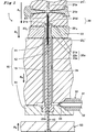
 本発明の射出成型用金型1の一形態の模式断面正面図を図1に示す。射出成型用金型1は、注射針61が外筒62に固着された針付きシリンジ60(図4A参照)を成形するためのものである。射出成型用金型1は、針付きシリンジ60の外筒62の内面を形成するコアピン13、そのコアピン13のピン基端側が嵌合する固定板14、及び金属製円筒状針管である注射針61をコアピン13のピン先端から挿入する貫通穴12を有する雄金型10と、コアピン13のピン基端側から貫通穴12に挿入された支持棒40と、雌金型開口部23bと連通し、外筒62の外面を形成する凹部24を有する雌金型20と、雄金型10と雌金型20により形成されたキャビティ空間20aに樹脂を注入するための樹脂注入ゲート33とを有している。支持棒40は、貫通穴12に挿入された注射針61の針基端部と当接し、注射針61を押し上げることができる。図1は、支持棒40が注射針61を押し上げる前の状態を示している。 FIG. 1 shows a schematic sectional front view of an embodiment of an injection mold 1 of the present invention. The injection mold 1 is for molding a syringe 60 with a needle (see FIG. 4A) in which an injection needle 61 is fixed to an outer cylinder 62. The injection mold 1 includes a core pin 13 that forms an inner surface of an outer cylinder 62 of a syringe 60 with a needle, a fixing plate 14 to which a pin proximal end of the core pin 13 is fitted, and an injection needle 61 that is a metal cylindrical needle tube. Are communicated with the male mold 10 having a through hole 12 for inserting the core pin 13 from the tip end of the core pin 13, the support rod 40 inserted into the through hole 12 from the pin proximal end side of the core pin 13, and the female mold opening 23b. A female mold 20 having a recess 24 that forms the outer surface of the outer cylinder 62, and a resin injection gate 33 for injecting resin into the cavity space 20a formed by the male mold 10 and the female mold 20 are provided. Yes. The support bar 40 can contact the needle proximal end portion of the injection needle 61 inserted into the through hole 12 and push up the injection needle 61. FIG. 1 shows a state before the support bar 40 pushes up the injection needle 61.
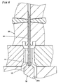
 雄金型10のコアピン13は、ピン先端とピン基端との間が円柱状であり、そこでの径が均等であり、ピン先端が略円錐状であって、その先端に隆起部11を有し、基端部が拡径した円柱状になるように、形成されている。コアピン13のピン先端近傍では、略円錐状の裾よりも隆起部11の方が急勾配になっている。コアピン13の中心軸上にピン先端からピン基端まで貫通した貫通穴12が貫設されている。貫通穴12の内径は、注射針61を挿入し易くするため、遊びを有するように、注射針61の外径よりも僅かに大きい。 The core pin 13 of the male die 10 has a cylindrical shape between the pin tip and the pin base end, the diameter thereof is uniform, the pin tip is substantially conical, and has a raised portion 11 at the tip. However, the base end portion is formed in a cylindrical shape with an enlarged diameter. In the vicinity of the pin tip of the core pin 13, the raised portion 11 is steeper than the substantially conical hem. A through hole 12 penetrating from the tip of the pin to the base end of the pin is provided on the central axis of the core pin 13. In order to facilitate insertion of the injection needle 61, the inner diameter of the through hole 12 is slightly larger than the outer diameter of the injection needle 61 so as to have play.
 隆起部11の外径は、1.5mm以下であり、好ましくは1.0mm以下であり、より好ましくは0.5mm以下である。また、隆起部11の高さは、1.5mm以下であり、好ましくは1.0mm以下であり、より好ましくは0.5mm以下である。なお、隆起部11は、小さければ小さいほど好ましく、無くても良い。 The outer diameter of the raised portion 11 is 1.5 mm or less, preferably 1.0 mm or less, more preferably 0.5 mm or less. Moreover, the height of the raised part 11 is 1.5 mm or less, Preferably it is 1.0 mm or less, More preferably, it is 0.5 mm or less. In addition, the raised part 11 is so preferable that it is small, and does not need to exist.
 貫通穴12は、円筒状であり、注射針61の外径より僅かに大きい内径を有している。貫通穴12の内径と注射針61の外径との径差により、注射針61を挿入でき且つ押し上げられる程度の僅かな遊びが設けられている。それにより、貫通穴12は、挿入された注射針61の側面を傷つけず、注射針61を傾倒させない。 The through hole 12 is cylindrical and has an inner diameter slightly larger than the outer diameter of the injection needle 61. Due to the difference in diameter between the inner diameter of the through hole 12 and the outer diameter of the injection needle 61, a slight play is provided so that the injection needle 61 can be inserted and pushed up. Thereby, the through hole 12 does not damage the side surface of the inserted injection needle 61 and does not tilt the injection needle 61.
 固定板14は、円柱状に拡径したコアピン13のピン基端が嵌合する嵌合穴を有し、その穴にコアピン13を嵌合して垂直に支持している。貫通穴12は、固定板14の嵌合穴から固定板14の底面まで、同径で同軸のまま貫通して延びている。 The fixing plate 14 has a fitting hole into which the pin base end of the core pin 13 whose diameter is expanded in a columnar shape is fitted, and the core pin 13 is fitted into the hole and vertically supported. The through hole 12 extends from the fitting hole of the fixed plate 14 to the bottom surface of the fixed plate 14 while having the same diameter and being coaxial.
 固定板14を介し、貫通穴12に、コアピン13のピン基端から、支持棒40が挿入されている。支持棒40は、その先端が注射針61と当接することで、注射針61を突き上げるように押し上げて支持しており、貫通穴12からの注射針61の脱落を防止している。支持棒40の先端面は、注射針61の基端と極力当接しないで注射針61を支持できるように、中心が凹んだ凹面になっている。 A support bar 40 is inserted into the through hole 12 from the pin base end of the core pin 13 through the fixing plate 14. The support rod 40 is supported by pushing up the injection needle 61 so that the injection needle 61 is pushed up by the tip of the support rod 40 being in contact with the injection needle 61, thereby preventing the injection needle 61 from falling off the through hole 12. The distal end surface of the support bar 40 is a concave surface with a recessed center so that the injection needle 61 can be supported without contacting the proximal end of the injection needle 61 as much as possible.
 支持棒40の基端部は、支持棒40を迫り上げる駆動板50に突き刺さって固定されている。駆動板50は、昇降駆動源(不図示)に接続されている。それにより、支持棒40の先端面は、貫通穴12内で昇降して、貫通穴12に挿入された注射針61の上下位置を調節できる。 The base end portion of the support rod 40 is fixed by being stabbed into a drive plate 50 that pushes up the support rod 40. The drive plate 50 is connected to a lift drive source (not shown). Thereby, the front end surface of the support bar 40 can be moved up and down in the through hole 12 to adjust the vertical position of the injection needle 61 inserted into the through hole 12.
 雌金型20は、固定板14に載置され、外筒62の胴部65及びフランジ68を形成するための胴部形成用雌金型23と、胴部形成用雌金型23上に載置され外筒62の筒先部63の基端部を形成するための筒先部形成用雌金型22と、さらに筒先部形成用雌金型22上に載置され筒先部63の頭部63a(図4B参照)を形成し、外筒62の形成時に注射針61を保持するための針保持用雌金型21とを、有している。 The female mold 20 is placed on the fixed plate 14 and mounted on the body forming female mold 23 for forming the body 65 and the flange 68 of the outer cylinder 62, and the body forming female mold 23. A cylindrical tip forming female die 22 for forming a base end portion of the cylindrical tip 63 of the outer cylinder 62, and a head 63a of the cylindrical tip 63 placed on the cylindrical tip forming female die 22 ( 4B) and a needle holding female mold 21 for holding the injection needle 61 when the outer cylinder 62 is formed.
 胴部形成用雌金型23は、胴部形成用雌金型23を貫通するコアピン13との間に外筒62の胴部65とフランジ68(図4A参照)とに対応するキャビティ空間20aを形成するための胴部形成空間部23aと、胴部形成空間部23aにコアピン13を挿入するための雌金型開口部23bを有している。雌金型開口部23b及び胴部形成空間部23aはコアピン13と同軸になっている。 The body forming female mold 23 has a cavity space 20a corresponding to the body 65 of the outer cylinder 62 and the flange 68 (see FIG. 4A) between the core pin 13 penetrating the body forming female mold 23. A body part forming space part 23a for forming and a female mold opening part 23b for inserting the core pin 13 into the body part forming space part 23a are provided. The female mold opening 23 b and the body forming space 23 a are coaxial with the core pin 13.
 筒先部形成用雌金型22は、胴部形成用雌金型23との対向面側に、外筒62の筒先部63の襞スカート部63c(図4B参照)を形成するための窪みである筒先形成空間部22cが設けられている。筒先形成空間部22cは、コアピン13と同軸になっている。 The tube tip portion forming female die 22 is a recess for forming a collar skirt portion 63c (see FIG. 4B) of the tube tip portion 63 of the outer tube 62 on the surface facing the body portion forming female die 23. A tube tip forming space 22c is provided. The tube tip forming space 22 c is coaxial with the core pin 13.
 なお、筒先部形成用雌金型22は、頭部形成空間部21eで形成される筒先部63の頭部63aと襞スカート部63c(図4B参照)を取出し可能にするため、左右に分離できる左型22及び右型22により構成される。左型22及び右型22が、左右対称に突き合わされ、それらの分割面が合わさることで、筒先形成空間部22cが形成される。 In addition, the female die 22 for forming the tube tip part can be separated into left and right parts so that the head part 63a and the collar skirt part 63c (see FIG. 4B) of the tube tip part 63 formed in the head forming space part 21e can be taken out. constituted by left die 22 L and the right type 22 R. Left die 22 L and the right type 22 R is butted symmetrically, that their divided surfaces come together, the cylindrical tip formed space portion 22c is formed.
 針保持用雌金型21は、筒先部形成用雌金型22との対向面側に、筒先部63の頭部63aを形成するための頭部形成空間部21eと、注射針61を保持する注射針保持穴21aとを有している。注射針保持穴21aと貫通穴12とが同軸になっている。 The needle holding female mold 21 holds the head forming space 21 e for forming the head 63 a of the tube tip 63 and the injection needle 61 on the side facing the tube tip forming female die 22. And a needle holding hole 21a. The injection needle holding hole 21a and the through hole 12 are coaxial.
 頭部形成空間部21eの周縁は、筒先形成空間部22cより大きくなっている。また、頭部形成空間部21eの中心に、注射針保持穴の開口部を囲むように凸部21cが設けられている。凸部21cの注射針保持穴の開口部の縁となる部分が面取りされ、注射針保持穴の開口部を僅かに広げる傾斜部21dが形成されている。これにより、注射針61を注射針保持穴21a内に挿入する際に、注射針61が僅かに傾倒していても注射針保持穴21a内にスムーズに誘い込まれる。 The periphery of the head forming space 21e is larger than the tube tip forming space 22c. A convex portion 21c is provided at the center of the head forming space portion 21e so as to surround the opening portion of the injection needle holding hole. A portion that is an edge of the opening of the injection needle holding hole of the convex portion 21c is chamfered, and an inclined portion 21d that slightly widens the opening of the injection needle holding hole is formed. Thereby, when inserting the injection needle 61 into the injection needle holding hole 21a, even if the injection needle 61 is slightly tilted, it is smoothly drawn into the injection needle holding hole 21a.
 この凸部21cの表面及び頭部形成空間部21eの内表面には型抜きしやすいように梨地加工や粗面加工が施されていることが好ましい。 It is preferable that the surface of the convex portion 21c and the inner surface of the head forming space portion 21e are subjected to a satin finish or a rough surface so as to be easily punched.
 また、針保持用雌金型21に、注射針61を挟持するための一対の挟持部21bが設けられている。一対の挟持部21bは、押し上げられた注射針61が、その中心軸とコアピン13の中心軸とを略一致させて注射針保持穴21a内で挟持して固定できるように、注射針61の軸方向と垂直方向に、針保持用雌金型21を挿脱可能に貫いている。 Also, the needle holding female die 21 is provided with a pair of clamping portions 21b for clamping the injection needle 61. The pair of clamping portions 21b are arranged so that the pushed-up injection needle 61 can be fixed by being clamped in the injection needle holding hole 21a so that the central axis of the injection needle 61 and the central axis of the core pin 13 are substantially coincided with each other. In the direction perpendicular to the direction, the needle holding female mold 21 is inserted and removed.
 胴部形成用雌金型23上に筒先部形成用雌金型22が載置され、さらに筒先部形成用雌金型22の上に針保持用雌金型21が載置されることにより、胴部形成空間部23aと、筒先形成空間部22c、頭部形成空間部21eとからなる凹部24が形成される。この凹部24は、外筒62の外面を成形するため、外筒62の外形に対応している。 By placing the barrel tip forming female die 22 on the barrel forming female die 23 and further placing the needle holding female die 21 on the barrel leading portion forming female die 22, A concave portion 24 is formed which includes a body portion forming space portion 23a, a tube tip forming space portion 22c, and a head portion forming space portion 21e. The recess 24 corresponds to the outer shape of the outer cylinder 62 in order to form the outer surface of the outer cylinder 62.
 コアピン13は、凹部24内へ同軸となるように挿入される。胴部形成用雌金型23と固定板14とが当接すると、凹部24、コアピン13及び固定板14により、外筒62を型取るキャビティ空間20aが形成される。キャビティ空間20a内で、コアピン13と筒先形成空間部22cと注射針保持穴21aとは同軸になっている。キャビティ空間20aは、針付きシリンジ60の外筒62の胴部65と筒先部63とフランジ68とを所期の厚みで形成するだけの隙間を構成している。 The core pin 13 is inserted into the recess 24 so as to be coaxial. When the body forming female die 23 and the fixing plate 14 come into contact with each other, a cavity space 20 a that molds the outer cylinder 62 is formed by the recess 24, the core pin 13 and the fixing plate 14. Within the cavity space 20a, the core pin 13, the tube tip forming space 22c, and the injection needle holding hole 21a are coaxial. The cavity space 20a forms a gap that forms the body 65, the tube tip 63, and the flange 68 of the outer tube 62 of the syringe 60 with the needle with the desired thickness.
 樹脂注入ゲート33は、キャビティ空間20aに樹脂を注入するためのもので、フランジ68の一端の側面を形成するように、胴部形成用雌金型23に1つだけ設けられている。熱溶融した熱可塑性樹脂をキャビティ空間20aへ誘導して注入する樹脂注入ノズル30が、樹脂注入ゲート33に、接続している。樹脂注入ノズル30は、管状で熱溶融した熱可塑性樹脂を流すランナ部31を、有している。ランナ部31は、樹脂注入ゲート33を介してキャビティ空間20aへ樹脂を充填することができるように、フランジ68を形成するキャビティ空間20aに連通している。ランナ部31の周囲に、ランナ部31内に流入した樹脂の溶融状態を保つヒータ32が設けられている。 The resin injection gate 33 is for injecting resin into the cavity space 20a, and only one is provided in the body forming female mold 23 so as to form a side surface of one end of the flange 68. A resin injection nozzle 30 that guides and injects the hot-melt thermoplastic resin into the cavity space 20 a is connected to the resin injection gate 33. The resin injection nozzle 30 has a runner portion 31 through which a thermoplastic resin melted in a tubular shape is flowed. The runner portion 31 communicates with the cavity space 20a that forms the flange 68 so that the cavity space 20a can be filled with resin via the resin injection gate 33. A heater 32 is provided around the runner portion 31 to maintain the molten state of the resin flowing into the runner portion 31.
 胴部形成用雌金型23が固定板14へ、次いで筒先部形成用雌金型22が胴部形成用雌金型23へ、次いで針保持用雌金型21が筒先部形成用雌金型22へ、順次当接し、射出形成するために雌金型20を連結するように、各金型21・22・23を連動させる単一の昇降駆動源(不図示)に繋がり又は各金型21・22・23を個別に夫々動作させる複数の昇降駆動源(不図示)に繋がっている。最後に、駆動板50が固定板14へ当接するように、駆動板50が各金型21・22・23と連動して又は個別に動作させる昇降駆動源(不図示)に繋がっていてもよい。雌金型20は、射出形成後に、針付きシリンジ60を取り出すために雌金型20を逆順で離反するように昇降駆動源に繋がっている。 The barrel forming female mold 23 is connected to the fixing plate 14, the tube tip forming female mold 22 is connected to the barrel forming female mold 23, and the needle holding female mold 21 is then used to form the tube tip forming female mold. 22 is connected to a single raising / lowering drive source (not shown) that interlocks the respective molds 21, 22, and 23 so that the female molds 20 are connected in order to abut against each other and perform injection molding. -It connects with the several raising / lowering drive source (not shown) which each operates 22 * 23. Finally, the drive plate 50 may be connected to a lifting drive source (not shown) that operates in conjunction with or individually with the molds 21, 22, and 23 so that the drive plate 50 contacts the fixed plate 14. . The female mold 20 is connected to an elevating drive source so as to separate the female mold 20 in reverse order to take out the syringe 60 with the needle after injection molding.
 コアピン13の先端部が、略半球状又は半多面体状でもよい。隆起部11の外形が、略円錐台状、略半円球状又は略多角錐台状でもよい。 The tip of the core pin 13 may be substantially hemispherical or semipolyhedral. The outer shape of the raised portion 11 may be a substantially truncated cone shape, a substantially semispherical shape, or a substantially polygonal frustum shape.
 針保持用雌金型21及び/又は胴部形成用雌金型23は、コアピン13の軸方向と直交する方向に開閉可能に対向し合う一対の金型であってもよい。 The needle holding female mold 21 and / or the body forming female mold 23 may be a pair of molds facing each other so as to be openable and closable in a direction orthogonal to the axial direction of the core pin 13.
 不動の固定板14を基準に、針保持用雌金型21、筒先部形成用雌金型22、胴部形成用雌金型23、駆動板50が駆動する例を示したが、相対的に同様に動作するのであれば、それらの何れかが不動であってもよく、全てが可動であってもよい。 Although an example in which the needle holding female die 21, the tube tip forming female die 22, the body forming female die 23, and the drive plate 50 are driven on the basis of the stationary stationary plate 14 is relatively shown, Any of them may be stationary or all may be movable as long as they operate similarly.
 射出成型用金型1を使用して、針付きシリンジ60を、以下のようにして製造する。 Using the injection mold 1, the syringe 60 with a needle is manufactured as follows.
 当初、針保持用雌金型21、筒先部形成用雌金型22、胴部形成用雌金型23、固定板14、駆動板50を、それぞれ離反させておく。このとき、雄金型10のコアピン13は、胴部形成用雌金型23内の胴部形成空間部23aから完全に抜けた状態となっている。また、支持棒40は、コアピン13の貫通穴12へ挿入された状態となっている。筒先部形成用雌金型22は、左型22及び右型22を突き合わして、形成されている。 Initially, the needle holding female die 21, the tube tip forming female die 22, the body forming female die 23, the fixing plate 14, and the driving plate 50 are separated from each other. At this time, the core pin 13 of the male die 10 is completely removed from the body portion forming space 23a in the body portion forming female die 23. Further, the support bar 40 is inserted into the through hole 12 of the core pin 13. Needle holder forming female mold 22 is Tsukiawashi the left die 22 L and the right mold 22 R, are formed.
 先ず、注射針61が貫通穴12内へ充分に挿入されつつ注射針61の針先が貫通穴12から上方に飛び出るように、支持棒40を、迫り上げておく。針基端部から注射針61を貫通穴12に挿入し、支持棒40で注射針61を突き上げて支える。胴部形成空間部23aとコアピン13とが同軸となるように、注射針61の針先端部よりも上方で、胴部形成用雌金型23を、配置しておく。コアピン13及び雌金型開口部20の中心軸を一致させたまま、固定板14と当接するまで、胴部形成用雌金型23を閉鎖方向Aに動かす。これにより、コアピン13を胴部形成空間部23a内に挿入する。 First, the support bar 40 is pushed up so that the needle tip of the injection needle 61 protrudes upward from the through hole 12 while the injection needle 61 is sufficiently inserted into the through hole 12. The injection needle 61 is inserted into the through hole 12 from the proximal end of the needle, and the injection needle 61 is pushed up and supported by the support rod 40. The body forming female die 23 is arranged above the needle tip of the injection needle 61 so that the body forming space 23a and the core pin 13 are coaxial. Core pin 13 and remains to match the central axis of the female mold openings 20, and the fixing plate 14 until the abutment to move the body portion forming the female mold 23 in the closing direction A 4. Thereby, the core pin 13 is inserted into the trunk portion forming space 23a.
 次いで、筒先形成空間部22cとコアピン13とが同軸となるように、注射針61の針先端部よりも上方で、筒先部形成用雌金型22を配置しておく。それらの中心軸を一致させたまま、胴部形成用雌金型23と当接するまで、筒先部形成用雌金型22を閉鎖方向Aに動かす。 Next, the tube tip forming female die 22 is arranged above the needle tip of the injection needle 61 so that the tube tip forming space 22c and the core pin 13 are coaxial. While it matches their central axis, until contact with the body portion forming the female mold 23 to move the needle holder forming the female mold 22 in the closing direction A 3.
 さらに、注射針保持穴21aとコアピン13とが同軸になるように、注射針61の針先端部よりも上方で、針保持用雌金型21を、配置しておく。それらの中心軸を一致させたまま、注射針保持穴21aに注射針61を挿入しながら、筒先部形成用雌金型22と当接するまで、針保持用雌金型21を閉鎖方向Aに動かす。それにより、注射針61の針先側が、注射針保持穴21aに挿入される。このとき注射針61の針先は、挟持部21bよりも下方に在る。 Furthermore, the needle holding female die 21 is arranged above the needle tip of the injection needle 61 so that the injection needle holding hole 21a and the core pin 13 are coaxial. While match their central axes, while inserting the needle 61 into the needle holding hole 21a, until contact with the cylindrical tip portion forming a female mold 22, the needle holding female die 21 in a closing direction A 2 move. Thereby, the needle tip side of the injection needle 61 is inserted into the injection needle holding hole 21a. At this time, the needle tip of the injection needle 61 is located below the clamping portion 21b.
 そして、雌金型20内に、胴部形成空間部23aと筒先形成空間部22cと頭部形成空間部21eとからなる凹部24が形作られ、雌金型20と雄金型10との間にキャビティ空間20aが形成される。注射針61は、コアピン13に深く挿入されているので、このキャビティ空間20aを形成する工程で、傾倒が抑えられている。 In the female mold 20, a concave portion 24 including a body portion forming space portion 23 a, a tube tip forming space portion 22 c, and a head forming space portion 21 e is formed, and between the female die 20 and the male die 10. A cavity space 20a is formed. Since the injection needle 61 is inserted deeply into the core pin 13, tilting is suppressed in the process of forming the cavity space 20a.
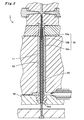
 次に、図1及び図2に示すように、注射針保持穴21aと筒先形成空間部22cと胴部形成空間部23aと頭部形成空間部21eとコアピン13とを同軸に保ったまま、駆動板50を、固定板14に当接するまで閉鎖方向Aに動かす。それに応じて、駆動板50に接続した支持棒40が迫り上がり、注射針61の針基端部を隆起部11の先端の近傍にまで押し上げる。注射針61の針先は、挟持部21bよりも上方に移動する。このとき、注射針61の針基端部から針孔への樹脂の流入を防ぐことができる程度に、できるだけ隆起部11の先端ぎりぎりまで注射針61の針基端部を押し上げる。注射針61は、注射針保持穴21a内で押し上げられ、その中心軸がコアピン13の中心軸と一致したまま保持される。そのため、射出成型用金型1は、隆起部11をできる限り小さくすることができ(図3参照)、隆起部11から転写されてできる針付きシリンジ60の外筒62の内壁の窪み部64が極めて小さくなる。従って、この窪み部64はデッドスペースに成り得るが、従来のように注射針61の傾倒を抑えるためにコアピン13に深く挿入されたままで成型されるもの(図6参照)よりも、数分の1乃至十数分の1程度に低減できる。 Next, as shown in FIGS. 1 and 2, the needle holding hole 21a, the tube tip forming space portion 22c, the body forming space portion 23a, the head forming space portion 21e, and the core pin 13 are driven while being kept coaxial. the plate 50 moves in the closing direction a 5 until it abuts against the fixed plate 14. Correspondingly, the support rod 40 connected to the drive plate 50 moves up and pushes the needle proximal end portion of the injection needle 61 to the vicinity of the distal end of the raised portion 11. The needle tip of the injection needle 61 moves upward from the clamping part 21b. At this time, the needle base end portion of the injection needle 61 is pushed up to the end of the raised portion 11 as much as possible to the extent that the resin can be prevented from flowing into the needle hole from the needle base end portion of the injection needle 61. The injection needle 61 is pushed up in the injection needle holding hole 21 a and is held with its central axis coinciding with the central axis of the core pin 13. Therefore, in the injection mold 1, the raised portion 11 can be made as small as possible (see FIG. 3), and the recessed portion 64 on the inner wall of the outer cylinder 62 of the syringe 60 with a needle formed by being transferred from the raised portion 11. Extremely small. Therefore, although this hollow part 64 can become a dead space, in order to suppress tilting of the injection needle 61 as in the prior art, it is several minutes more than what is molded while being inserted deeply into the core pin 13 (see FIG. 6). It can be reduced to about 1 to 1/10.
 その後、挟持部21bを閉鎖方向Aに動かす。これにより、注射針61は、それとコアピン13とが略同軸になっている状態で、固定できる。射出成型用金型1の型締めをした後、ランナ部31を経由させて樹脂注入ゲート33からキャビティ空間20aに溶融した樹脂を注入して、針付きシリンジ60を成形するために射出成型を行う。 Then, moving the clamping portion 21b in the closing direction A 1. Thereby, the injection needle 61 can be fixed in a state where it and the core pin 13 are substantially coaxial. After the mold 1 for injection molding is clamped, the molten resin is injected into the cavity space 20a from the resin injection gate 33 through the runner portion 31, and injection molding is performed to mold the syringe 60 with a needle. .
 射出成型により、針付きシリンジ60のフランジ68・胴部65・筒先部63に対応するキャビティ空間20aに、順次、熱溶融した熱可塑性樹脂が充填されていく。暫く樹脂を充填し続けると、筒先部63の頭部63aに対応するキャビティ空間20aにまで充填され尽くされる。キャビティ空間20a内の熱溶融していた樹脂が冷却されて固化する。このとき、所定位置に保持された注射針61は、それの針基端部が僅かに隆起部11内に収まっているので、基端側から針孔内への樹脂の侵入が防がれつつ、樹脂が筒先形成空間部22c内で注射針61の略半分を囲むように固化する。その結果、注射針61は、針孔が塞がれることなく、外筒62に確りと固着して保持される。同時に、キャビティ空間20a内に配置したコアピン13により、薬剤を充填する外筒62の内空66と、その薬剤を内空66に注入する開口部67とが形成され、キャビティ空間20aの凹部24により、外筒62の外壁が形成される(図4A参照)。 The cavity space 20a corresponding to the flange 68, the body portion 65, and the tube tip portion 63 of the syringe 60 with a needle is sequentially filled with the hot-melted thermoplastic resin by injection molding. If the resin is continuously filled for a while, the cavity space 20a corresponding to the head portion 63a of the tube tip portion 63 is completely filled. The resin that has been thermally melted in the cavity space 20a is cooled and solidified. At this time, since the needle proximal end of the injection needle 61 held at a predetermined position is slightly within the raised portion 11, the resin can be prevented from entering the needle hole from the proximal end side. The resin is solidified so as to surround substantially half of the injection needle 61 in the tube tip forming space 22c. As a result, the injection needle 61 is securely fixed and held on the outer cylinder 62 without the needle hole being blocked. At the same time, the core pin 13 disposed in the cavity space 20a forms an inner space 66 of the outer cylinder 62 that fills the medicine and an opening 67 that injects the medicine into the inner space 66, and is formed by the recess 24 of the cavity space 20a. The outer wall of the outer cylinder 62 is formed (see FIG. 4A).
 その後、樹脂が固化したら、挟持部21bを閉鎖方向Aの反対方向へ動かして開放し、針保持用雌金型21を移動可能にする。次いで、針保持用雌金型21を閉鎖方向Aの反対方向へ動かす。さらに、筒先部形成用雌金型22を左型22Lと右型22とに分解した後、閉鎖方向Aの反対方向へ動かす。その後、胴部形成用雌金型23を閉鎖方向Aの反対方向へ動かして、射出成型用金型1の型開きを行う。成形した針付きシリンジ60を、コアピン13から抜き取って取出す。必要に応じ、樹脂注入ゲート33のためにフランジ68に生じたバリを取り除く。 Thereafter, when the resin is solidified, the clamping portions 21b open and move in the opposite direction of the closing direction A 1, permits moving the needle holding female mold 21. Then, move the needle holding female mold 21 in the opposite direction of the closing direction A 2. Furthermore, after decomposing the needle holder forming female die 22 to the left die 22L and the right mold 22 R, it moves in the opposite direction of the closing direction A 3. Then, by moving the body portion forming the female mold 23 in the opposite direction of the closing direction A 4, it performs mold opening of the injection mold 1. The formed syringe 60 with a needle is extracted from the core pin 13 and taken out. If necessary, burrs generated on the flange 68 for the resin injection gate 33 are removed.
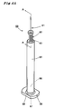
 このように製造された本発明の針付きシリンジ60は、図4Aに示すように、樹脂からなる外筒62とその筒先部63に一体接合された注射針61とにより形成されている。 The needle-equipped syringe 60 of the present invention thus manufactured is formed by an outer cylinder 62 made of resin and an injection needle 61 integrally joined to the cylinder tip 63 as shown in FIG. 4A.
 外筒62は、円筒状であって、薬剤を充填する内空66を有し、先端に設けられた筒先部63と、その周囲に連続し、基端に向かって延びる周壁からなる胴部65と、基端に設けられた開口部67とを有している。開口部67は、胴部65の軸に対して垂直かつ外方へ延びたフランジ68を有している。フランジ68は、針付きシリンジ60が成形される時に樹脂注入ゲート33で形成されるゲート跡69を、外面に1つだけ有している。 The outer cylinder 62 has a cylindrical shape and has an inner space 66 filled with a medicine, a cylinder tip part 63 provided at the distal end, and a body part 65 made of a peripheral wall that continues to the periphery and extends toward the proximal end. And an opening 67 provided at the base end. The opening 67 has a flange 68 that extends perpendicularly to the axis of the body 65 and outwards. The flange 68 has only one gate mark 69 formed on the resin injection gate 33 when the needle-equipped syringe 60 is molded on the outer surface.
 注射針61は、筒先部63に貫通されている。筒先部63は、その内面に、隆起部11から転写された略円錐台状の窪み部64を有する。 The injection needle 61 is penetrated through the tube tip 63. The tube tip portion 63 has a substantially truncated cone-shaped recess portion 64 transferred from the raised portion 11 on the inner surface thereof.
 窪み部64の外径は、1.5mm以下であり、好ましくは1.0mm以下であり、より好ましくは0.5mm以下である。また、窪み部64の深さは、1.5mm以下であり、好ましくは1.0mm以下であり、より好ましくは0.5mm以下である。なお、窪み部は小さければ小さいほど好ましく、無くても良い。 The outer diameter of the hollow portion 64 is 1.5 mm or less, preferably 1.0 mm or less, more preferably 0.5 mm or less. Moreover, the depth of the hollow part 64 is 1.5 mm or less, Preferably it is 1.0 mm or less, More preferably, it is 0.5 mm or less. It should be noted that the smaller the recess, the better.
 注射針61の針基端部は、窪み部64より胴部65の内空66へ僅かに突き出している。内空66へ突き出している針基端部の長さは、1.5mm以下であり、好ましくは1.0mm以下であり、より好ましくは0.5mm以下で、さらに好ましくは0mmである。これにより、窪み部64は、注射針61の基端と、隆起部11の先端に対応する窪み部64の先端(底部)との間に形成されるデッドスペースを極力小さくすることができる。デッドスペースに、薬液が充填されても、極僅かである。そのため、充填された薬液を排出し尽くして、薬液の有効活用に貢献できる。 The needle proximal end of the injection needle 61 slightly protrudes from the recess 64 to the inner space 66 of the body 65. The length of the needle proximal end protruding to the inner space 66 is 1.5 mm or less, preferably 1.0 mm or less, more preferably 0.5 mm or less, and further preferably 0 mm. Thereby, the hollow part 64 can make the dead space formed between the base end of the injection needle 61 and the front-end | tip (bottom part) of the hollow part 64 corresponding to the front-end | tip of the protruding part 11 as small as possible. Even if the dead space is filled with the chemical solution, it is very small. Therefore, it is possible to exhaust the filled chemical solution and contribute to the effective use of the chemical solution.
 注射針61は、その中央部から先端の刃先部までが筒先部63から先端側へ突き出た状態で保持される。 The injection needle 61 is held in a state in which the portion from the center portion to the blade tip portion at the tip protrudes from the tube tip portion 63 to the tip side.
 保持されている注射針61は、その軸が、全く傾斜しておらず、又は殆ど傾斜していないことにより、胴部65の外周面の軸と略平行であることが好ましい。ここでいう略平行とは、注射針61の軸が外筒62の胴部65の外周面の軸と完全に平行であるか、胴部65の外周面の中心軸に対する注射針61の中心軸の傾きが2度以下であることをいう。 It is preferable that the axis of the held injection needle 61 is substantially parallel to the axis of the outer peripheral surface of the body portion 65 because the axis is not inclined at all or is hardly inclined. Here, “substantially parallel” means that the axis of the injection needle 61 is completely parallel to the axis of the outer peripheral surface of the barrel 65 of the outer cylinder 62 or the central axis of the injection needle 61 with respect to the central axis of the outer peripheral surface of the barrel 65. The inclination of the angle is 2 degrees or less.
 筒先部63は、襞スカート部63cと頭部63aとを有している。襞スカート部63c上に幾分拡径した円環状の頭部63aが搭載され、その円環状の窪みの中央が円錐状に盛り上がりつつ注射針61で貫かれた環状傾斜63bを、有している。 The tube tip part 63 has a collar skirt part 63c and a head part 63a. An annular head portion 63a having a somewhat enlarged diameter is mounted on the heel skirt portion 63c, and has an annular slope 63b penetrated by the injection needle 61 while the center of the annular recess rises conically. .
 窪み部64は、隆起部11の形状に応じて、略円錐台状、略半円球状又は略多角錐台状に形成されていてもよい。 The hollow portion 64 may be formed in a substantially truncated cone shape, a substantially semispherical shape, or a substantially polygonal frustum shape according to the shape of the raised portion 11.
 頭部63aの中央は、傾斜部21dの形状に応じて、注射針61の周囲でドーム状に盛り上がっていてもよい。 The center of the head 63a may be raised in a dome shape around the injection needle 61 in accordance with the shape of the inclined portion 21d.
 筒先部63の襞スカート部63cの形状は、筒先部63が注射針61を保持するための強度を確保できれば、四角柱状、六角柱状等の多角柱状、又は円柱状であってもよい。 The shape of the collar skirt portion 63c of the tube tip portion 63 may be a polygonal column shape such as a quadrangular column shape, a hexagonal column shape, or a column shape as long as the tube tip portion 63 can secure the strength for holding the injection needle 61.
 外筒62を構成する樹脂は、耐薬品性、耐熱性、ガス・菌バリア性、生体への安全性、透明性等の観点から選択される。例えばポリエチレン、ポリプロピレン、シクロオレフィンポリマーのようなポリオレフィン樹脂;ポリスチレン;ポリカーボネート;ポリエチレンテレフタレートのようなポリエステル;ポリアミドで例示される熱可塑性樹脂が用いられる。特に、内部に収容された薬液を外側から目視にて確認できるように透明であり、かつ薬液との相互作用が少ない樹脂である環状オレフィンホモポリマー又は環状オレフィンコポリマーを用いることが好ましい。 The resin constituting the outer cylinder 62 is selected from the viewpoints of chemical resistance, heat resistance, gas / bacteria barrier properties, safety to living bodies, transparency, and the like. For example, a thermoplastic resin exemplified by polyolefin resin such as polyethylene, polypropylene, cycloolefin polymer; polystyrene; polycarbonate; polyester such as polyethylene terephthalate; In particular, it is preferable to use a cyclic olefin homopolymer or a cyclic olefin copolymer, which is a resin that is transparent so that the chemical liquid accommodated therein can be visually confirmed from the outside and has little interaction with the chemical liquid.
 注射針61の材料は、射出成型に耐え得る材料であって、耐薬品性、耐熱性、ガス・菌バリア性、生体への安全性等の観点から選択される。例えばステンレス及びニッケルフリーステンレスを挙げることができるが、成形が比較的容易で安価なステンレスが好ましい。 The material of the injection needle 61 is a material that can withstand injection molding, and is selected from the viewpoints of chemical resistance, heat resistance, gas / bacteria barrier properties, safety to the living body, and the like. For example, stainless steel and nickel-free stainless steel can be mentioned, but stainless steel that is relatively easy to form and inexpensive is preferable.
 注射針61の針基端部が筒先部63に保持されている位置は、筒先部63の中心である必要はなく、胴部65に対して径方向に幾分ずらしていてもよい。また、注射針61の刃面がフランジ68側に向くように、刃面をセンサーで検知してから注射針61の向きを調整した後、貫通穴12に挿入してもよい。 The position where the needle base end portion of the injection needle 61 is held by the tube tip portion 63 does not have to be at the center of the tube tip portion 63 and may be somewhat shifted in the radial direction with respect to the body portion 65. Further, the direction of the injection needle 61 may be adjusted after the blade surface is detected by a sensor so that the blade surface of the injection needle 61 faces the flange 68, and then inserted into the through hole 12.
 図5に、射出成型用金型1の別な形態の模式断面正面図を示す。この射出成型用金型1は、図1のコアピン13に代えて、内部に冷却機構を備えたコアピン13としたものである。冷却機構は、樹脂注入ゲート33より注入された熱溶融した熱可塑性樹脂を熱伝導により冷却するもので、例えば冷却水を流して熱交換させる水冷機構である。 FIG. 5 shows a schematic cross-sectional front view of another form of the injection mold 1. The injection mold 1 is a core pin 13 having a cooling mechanism inside instead of the core pin 13 of FIG. The cooling mechanism cools the hot-melted thermoplastic resin injected from the resin injection gate 33 by heat conduction. For example, the cooling mechanism is a water-cooling mechanism that exchanges heat by flowing cooling water.
 具体的には、冷却機構は、コアピン13内部に冷却水を流す溝を、有するものである。コアピン13は、内部が円筒状にくり抜かれており、そこへ円筒状の芯部15が嵌合してねじ込まれたものである。コアピン13は、芯部15ごと、中心軸上に、ピン先端からピン基端まで貫通した貫通穴12が貫設されている。 Specifically, the cooling mechanism has a groove through which cooling water flows inside the core pin 13. The core pin 13 is hollowed in a cylindrical shape, and a cylindrical core portion 15 is fitted and screwed into the core pin 13. The core pin 13 is provided with a through hole 12 penetrating from the tip end of the pin to the base end of the pin on the central axis together with the core portion 15.
 芯部15は、線対称に下端から上端まで芯棒15cの側面に一対の縦溝15bが設けられ、各縦溝15bを上端の縁で繋ぐ半環状の横溝15aが設けられている。一方の縦溝15bから横溝15aを経て他方の縦溝15bへ冷却水が流れるように、縦溝15bは、固定板14に開けられた管14aへ、下端で接続している。横溝15a及び縦溝15bを流れる冷却水は、コアピン13内の流路に流動させて、射出成型用金型1内でキャビティ空間20aへ注入された熱溶融した熱溶融性樹脂を冷却して、固化させる。 The core portion 15 is provided with a pair of vertical grooves 15b on the side surface of the core rod 15c from the lower end to the upper end in a line symmetry, and a semi-annular horizontal groove 15a that connects each vertical groove 15b with the edge of the upper end. The vertical groove 15b is connected at the lower end to the pipe 14a opened in the fixed plate 14 so that the cooling water flows from one vertical groove 15b to the other vertical groove 15b through the horizontal groove 15a. The cooling water flowing through the horizontal grooves 15a and the vertical grooves 15b is caused to flow in the flow path in the core pin 13 to cool the hot-melt hot-melt resin injected into the cavity space 20a in the injection mold 1 and Solidify.
 なお、冷却機構は、冷媒で冷やされた熱伝導性金属棒であってもよい。 Note that the cooling mechanism may be a heat conductive metal rod cooled by a refrigerant.
 本発明の射出成型用金型を用いた針付きシリンジの製造方法は、デッドスペースが少なく、注射針が外筒に対して傾斜していない針付きシリンジを、製造するのに用いることができる。その針付きシリンジは、ワクチンのような生物製剤等の皮下注射に用いることができる。 The method of manufacturing a syringe with a needle using the injection mold of the present invention can be used to manufacture a syringe with a needle that has little dead space and the injection needle is not inclined with respect to the outer cylinder. The needled syringe can be used for subcutaneous injection of biologics such as vaccines.
1:射出成型用金型、 10:雄金型、 11:隆起部、 12:貫通穴、 13:コアピン、 14:固定板、 14a:管、 15:芯部、 15a:横溝、 15b:縦溝、 15c:芯棒、 16:挿入部、 20:雌金型、 20a:キャビティ空間、 21:針保持用雌金型、 21a:注射針保持穴、 21b:挟持部、 21c:凸部、 21d:傾斜部、 21e:頭部形成空間部、 22:筒先部形成用雌金型、 22:左型、 22:右型、 22c:筒先形成空間部、 23:胴部形成用雌金型、 23a:胴部形成空間部、 23b:雌金型開口部、 24:凹部、 30:樹脂注入ノズル、 31:ランナ部、 32:ヒータ、 33:樹脂注入ゲート、 40:支持棒、 50:駆動板、 60:針付きシリンジ、 61:注射針、 62:外筒、 63:筒先部、 63a:頭部、 63b:環状傾斜、 63c:襞スカート部、 64:窪み部、 65:胴部、 66:内空、 67:開口部、 68:フランジ、 69:ゲート跡、 A1,2,3,4,:閉鎖方向 1: injection mold, 10: male mold, 11: raised portion, 12: through hole, 13: core pin, 14: fixing plate, 14a: pipe, 15: core portion, 15a: transverse groove, 15b: longitudinal groove 15c: core rod, 16: insertion part, 20: female mold, 20a: cavity space, 21: female mold for needle holding, 21a: injection needle holding hole, 21b: clamping part, 21c: convex part, 21d: inclined portion, 21e: head forming space, 22: cylindrical tip portion forming the female mold, 22 L: left die, 22 R: right type 22c: cylindrical tip forming space, 23: body portion forming the female mold, 23a: body part forming space part, 23b: female mold opening, 24: recessed part, 30: resin injection nozzle, 31: runner part, 32: heater, 33: resin injection gate, 40: support rod, 50: drive plate , 60: syringe with needle, 61: injection needle, 62: outer cylinder, 63 Needle holder, 63a: Head, 63 b: inclined annular, 63c: folds skirt, 64: recess, 65: body portion, 66: inner space, 67: opening, 68: flange, 69: gate mark, A 1 , A 2, A 3, A 4, A 5: the closing direction

Claims (13)

  1.  筒状の胴部、前記胴部の先端に設けられた筒先部、及び前記胴部の基端に設けられた開口部を有し、樹脂で成形された外筒と、針先端部及び針基端部を有し前記針基端部側が前記筒先部に保持された注射針とを備え、前記注射針と前記外筒とが一体に成形されている針付きシリンジを成形するための射出成型用金型であって、
     ピン先端及びピン基端を含み前記外筒の内面を成形するコアピンと、前記ピン先端から前記ピン基端まで貫通し前記ピン先端から前記注射針の前記針基端部が挿入される貫通穴とを有する雄金型と、
     雌金型開口部と、前記雌金型開口部に連通し前記外筒の外面を成形する凹部と、前記雌金型開口部と反対側に前記貫通穴と同軸上に設けられ前記凹部に連通し前記注射針を保持する注射針保持穴とを有する雌金型と、
     前記ピン基端から前記貫通穴に挿入され、前記ピン先端から挿入された前記注射針の前記針基端部を突き上げて支えつつ、前記針基端部を前記ピン先端の近傍まで押し上げる支持棒と、
     前記凹部と、前記雌金型開口部から挿入された前記コアピンとから形成されるキャビティ空間に前記樹脂を注入するための樹脂注入ゲートとを、
    備えることを特徴とする射出成型用金型。
    An outer cylinder formed of a resin having a cylindrical body part, a cylinder tip part provided at a distal end of the body part, and an opening part provided at a proximal end of the body part, a needle distal end part, and a needle base An injection needle for forming a syringe with a needle having an end portion and an injection needle having the needle proximal end portion held by the tube tip portion, and the injection needle and the outer tube are integrally formed Mold,
    A core pin that forms the inner surface of the outer cylinder including a pin distal end and a pin proximal end; and a through hole that penetrates from the pin distal end to the pin proximal end and into which the needle proximal end portion of the injection needle is inserted from the pin distal end. A male mold having
    A female mold opening, a recess communicating with the female mold opening, and forming an outer surface of the outer cylinder, and provided on the opposite side of the female mold opening and coaxially with the through hole and communicating with the recess A female mold having a needle holding hole for holding the needle,
    A support rod which is inserted into the through hole from the pin proximal end and pushes up the needle proximal end portion of the injection needle inserted from the pin distal end and pushes up the needle proximal end portion to the vicinity of the pin distal end. ,
    A resin injection gate for injecting the resin into a cavity space formed by the recess and the core pin inserted from the female mold opening;
    An injection mold characterized by comprising.
  2.  迫り上げられた前記支持棒の先端と前記ピン先端との距離が最大で1.5mmであるように、前記支持棒の迫り上げが調節されることを特徴とする請求項1に記載の射出成型用金型。 2. The injection molding according to claim 1, wherein the push-up of the support bar is adjusted so that a distance between the tip of the support bar pushed up and the tip of the pin is 1.5 mm at the maximum. Mold.
  3.  前記コアピンが、前記ピン先端に前記針基端部を包囲して前記注射針内への前記樹脂の流入を防止する隆起部を有していることを特徴とする請求項2に記載の射出成型用金型。 The injection molding according to claim 2, wherein the core pin has a raised portion that surrounds the proximal end portion of the needle at the distal end of the pin and prevents the resin from flowing into the injection needle. Mold.
  4.  前記隆起部の外径が最大で1.5mmであり、前記隆起部の高さが最大で1.5mmであることを特徴とする請求項3に記載の射出成型用金型。 The injection mold according to claim 3, wherein an outer diameter of the raised portion is 1.5 mm at the maximum and a height of the raised portion is 1.5 mm at the maximum.
  5.  前記雄金型が、前記樹脂注入ゲートより注入された前記樹脂を熱伝導により冷却する冷却機構を、前記コアピン内に有していることを特徴とする請求項1に記載の射出成型用金型。 2. The injection mold according to claim 1, wherein the male mold has a cooling mechanism in the core pin for cooling the resin injected from the resin injection gate by heat conduction. .
  6.  前記雌金型が、前記注射針保持穴において前記注射針を挟持する挟持部を有していることを特徴とする請求項1に記載の射出成型用金型。 2. The injection mold according to claim 1, wherein the female mold has a holding portion for holding the injection needle in the injection needle holding hole.
  7.  筒状の胴部、前記胴部の先端に設けられた筒先部、及び前記胴部の基端に設けられた開口部を有し、樹脂で成形された外筒と、針先端部及び針基端部を有し前記針基端部側が前記筒先部に保持された注射針とを備え、前記注射針と前記外筒とが一体に成形されている針付きシリンジを、射出成型用金型によって成形する針付きシリンジの製造方法であって、
     ピン先端及びピン基端を含み前記外筒の内面を成形するコアピンと前記ピン先端から前記ピン基端まで貫通した貫通穴とを有する雄金型と、雌金型開口部と、前記雌金型開口部に連通し前記外筒の外面を成形する凹部と、前記雌金型開口部と反対側に前記貫通穴と同軸上に設けられ前記凹部に連通する注射針保持穴とを有する雌金型と、前記貫通穴内に前記ピン基端側から挿入された支持棒とを準備する工程、
     前記針基端部から前記注射針を、前記貫通穴内へ前記ピン先端側より挿入し、前記支持棒で前記注射針の前記針基端部を突き上げて支える工程、
     前記雌金型開口部から前記凹部の内空へ、前記コアピンを挿入して、前記凹部と前記コアピンとから形成されるキャビティ空間を形成する工程、
     前記貫通穴に挿入された支持棒を迫り上げて、前記針基端部を前記ピン先端の近傍にまで押し上げるとともに、前記注射針保持穴で前記注射針を保持する工程、及び
     前記キャビティ空間に前記樹脂を注入し、前記注射針と前記外筒とを一体に成形する工程を、
    有することを特徴とする針付きシリンジの製造方法。
    An outer cylinder formed of a resin having a cylindrical body part, a cylinder tip part provided at a distal end of the body part, and an opening part provided at a proximal end of the body part, a needle distal end part, and a needle base An injection needle having an end portion and a needle base end side held by the tube tip portion, and the injection needle and the outer tube are integrally formed by an injection mold A method of manufacturing a syringe with a needle to be molded,
    A male mold having a core pin that includes the tip of the pin and a base of the pin to form the inner surface of the outer cylinder, a through hole that penetrates from the tip of the pin to the base of the pin, a female mold opening, and the female mold A female mold having a recess communicating with the opening and forming the outer surface of the outer cylinder, and an injection needle holding hole provided coaxially with the through-hole on the opposite side of the female mold opening and communicating with the recess. And a step of preparing a support rod inserted from the pin base end side into the through hole,
    Inserting the injection needle from the needle proximal end portion into the through hole from the pin distal end side, and pushing up and supporting the needle proximal end portion of the injection needle with the support rod;
    Inserting the core pin from the female mold opening to the inner space of the recess to form a cavity space formed by the recess and the core pin;
    Pushing up the support rod inserted into the through hole to push the needle proximal end up to the vicinity of the tip of the pin and holding the injection needle in the injection needle holding hole; and Injecting resin and molding the injection needle and the outer cylinder integrally,
    A method for producing a syringe with a needle, comprising:
  8.  前記支持棒の先端と前記ピン先端との距離が最大で1.5mmとなるまで前記支持棒を迫り上げることを特徴とする請求項7に記載の針付きシリンジの製造方法。 The method for manufacturing a syringe with a needle according to claim 7, wherein the support rod is pushed up until the distance between the tip of the support rod and the tip of the pin reaches 1.5 mm at the maximum.
  9.  前記ピン先端に前記針基端部を包囲して前記貫通穴への前記樹脂の流入を防止する隆起部を形成しておき、前記キャビティ空間に前記樹脂を注入して、前記隆起部に対応する窪み部を前記外筒に形成し前記窪み部に前記針基端部を収めることを特徴とする請求項7に記載の針付きシリンジの製造方法。 A bulge is formed at the tip of the pin so as to surround the needle proximal end to prevent the resin from flowing into the through hole, and the resin is injected into the cavity space to correspond to the bulge. The method for producing a syringe with a needle according to claim 7, wherein a hollow portion is formed in the outer cylinder, and the needle proximal end portion is housed in the hollow portion.
  10.  前記隆起部の外径が最大で1.5mm、高さが最大で1.5mmとなるように、前記隆起部を形成しておくことを特徴とする請求項7に記載の針付きシリンジの製造方法。 The said protruding part is formed so that the outer diameter of the said protruding part may be 1.5 mm at the maximum and 1.5 mm at the maximum, The manufacture of the syringe with a needle | hook of Claim 7 characterized by the above-mentioned. Method.
  11.  前記注射針保持穴において前記注射針を挟持する挟持部を前記雌金型に設けておき、前記支持棒が迫り上がることにより押し上げられた前記注射針を、前記注射針保持穴内で支えつつ、前記挟持部で挟持することを特徴とする請求項7に記載の針付きシリンジの製造方法。 A holding portion for holding the injection needle in the injection needle holding hole is provided in the female mold, and the injection needle pushed up by the support rod being pushed up is supported in the injection needle holding hole. The method for manufacturing a syringe with a needle according to claim 7, wherein clamping is performed by a clamping unit.
  12.  前記樹脂注入ゲートより注入された前記樹脂を熱伝導により冷却する冷却機構を前記コアピン内に設けておき、
     前記キャビティ内に注入された前記樹脂を前記冷却機構で冷却させて固化させ前記注射針と前記外筒とを一体に成形してから、それを取り出すことを特徴とする請求項7に記載の針付きシリンジの製造方法。
    A cooling mechanism for cooling the resin injected from the resin injection gate by heat conduction is provided in the core pin,
    The needle according to claim 7, wherein the resin injected into the cavity is cooled and solidified by the cooling mechanism, and the injection needle and the outer cylinder are integrally formed, and then the needle is taken out. A manufacturing method of a syringe with attachment.
  13.  筒状の胴部、前記胴部の先端に設けられた筒先部、及び前記胴部の基端に設けられた開口部を有し、樹脂で成形された外筒と、前記筒先部に保持された注射針とを備え、前記注射針と前記外筒とが一体に成形され、前記胴部内に薬液を充填可能な針付きシリンジであって、
     前記筒先部の基端には、前記外筒の内壁に囲まれ、先端側に窪んだ窪み部が形成されており、
     前記窪み部の外径が最大で1.5mmであり、前記窪み部の深さが最大で1.5mmであり、
     前記注射針の針基端部が、前記窪み部内に最大で1.5mm突出していることを特徴とする針付きシリンジ。
    A cylindrical barrel, a barrel tip provided at the distal end of the barrel, and an opening provided at the proximal end of the barrel, and is held by the barrel and the outer cylinder made of resin. A syringe with a needle in which the injection needle and the outer cylinder are integrally formed, and the body portion can be filled with a chemical solution,
    The base end of the tube tip portion is surrounded by the inner wall of the outer tube, and is formed with a recessed portion that is recessed on the distal end side,
    The outer diameter of the recess is at most 1.5 mm, the depth of the recess is at most 1.5 mm,
    A syringe with a needle, wherein a needle base end portion of the injection needle protrudes up to 1.5 mm into the recess.
PCT/JP2015/058948 2014-03-31 2015-03-24 Injection molding mold WO2015151936A1 (en)

Priority Applications (3)

Application Number Priority Date Filing Date Title
JP2016511567A JP6510492B2 (en) 2014-03-31 2015-03-24 Injection mold
EP15772956.7A EP3127677A4 (en) 2014-03-31 2015-03-24 Injection molding mold
US15/280,568 US10493216B2 (en) 2014-03-31 2016-09-29 Method for producing a needle-equipped syringe

Applications Claiming Priority (2)

Application Number Priority Date Filing Date Title
JP2014071911 2014-03-31
JP2014-071911 2014-03-31

Related Child Applications (1)

Application Number Title Priority Date Filing Date
US15/280,568 Continuation US10493216B2 (en) 2014-03-31 2016-09-29 Method for producing a needle-equipped syringe

Publications (1)

Publication Number Publication Date
WO2015151936A1 true WO2015151936A1 (en) 2015-10-08

Family

ID=54240263

Family Applications (1)

Application Number Title Priority Date Filing Date
PCT/JP2015/058948 WO2015151936A1 (en) 2014-03-31 2015-03-24 Injection molding mold

Country Status (4)

Country Link
US (1) US10493216B2 (en)
EP (1) EP3127677A4 (en)
JP (2) JP6510492B2 (en)
WO (1) WO2015151936A1 (en)

Cited By (5)

* Cited by examiner, † Cited by third party
Publication number Priority date Publication date Assignee Title
JP2017169896A (en) * 2016-03-24 2017-09-28 テルモ株式会社 Medical needle and manufacturing method thereof
DE102016107131A1 (en) * 2016-04-18 2017-10-19 Gerresheimer Regensburg Gmbh Tool for manufacturing an injection device and method for producing an injection device
DE102016118768A1 (en) * 2016-10-04 2018-04-05 Gerresheimer Regensburg Gmbh Method for producing a syringe with an integrated closure element
CN109249592A (en) * 2017-07-13 2019-01-22 格雷斯海姆里根斯堡有限公司 Method for manufacturing the injection mold of moulding and for manufacturing moulding
CN114344609A (en) * 2015-10-09 2022-04-15 维斯特医药服务以色列有限公司 Cartridge and method of manufacturing cartridge

Families Citing this family (2)

* Cited by examiner, † Cited by third party
Publication number Priority date Publication date Assignee Title
EP3109026B1 (en) 2015-06-23 2018-11-28 Gerresheimer Regensburg GmbH Device for the production of plastics objects with inserts
DE102018121835A1 (en) * 2018-09-07 2020-03-12 Gerresheimer Regensburg Gmbh Method and device for producing a hollow injection molded part

Citations (3)

* Cited by examiner, † Cited by third party
Publication number Priority date Publication date Assignee Title
JPH0966104A (en) * 1995-09-01 1997-03-11 Koki Eng:Kk Syringe integrated with needle
WO2008139982A1 (en) * 2007-04-26 2008-11-20 Daikyo Seiko, Ltd. Syringe barrel with injection needle, syringe with injection needle, die for molding syringe barrel with injection needle, and method of molding syringe barrel with injection needle
JP2011510836A (en) * 2008-01-15 2011-04-07 ウエスト・ファーマシューティカル・サービシーズ・インコーポレイテッド Method for forming collet mechanism and cannula into syringe barrel

Family Cites Families (11)

* Cited by examiner, † Cited by third party
Publication number Priority date Publication date Assignee Title
US3330004A (en) * 1963-11-04 1967-07-11 Nosco Plastics Hypodermic syringe
US4956143A (en) * 1981-09-16 1990-09-11 Taut, Inc. Method and apparatus for the multi-unit production of thin-walled tubular products utilizing an injection molding technique
US5380301A (en) * 1992-07-10 1995-01-10 Sherwood Medical Company Catheter/hub strain relief and method of manufacture thereof
US7842217B2 (en) * 2007-03-28 2010-11-30 Benlan, Inc. Enteral-only syringe and method of manufacturing same
US8721603B2 (en) * 2008-01-15 2014-05-13 West Pharmaceutical Services, Inc. Syringe with co-molded hub and cannula
CN102264524B (en) * 2008-12-24 2014-11-26 Ssb技术有限公司 Moulding cannulae and small deep holes
CN103096953B (en) * 2010-09-29 2016-03-16 泰尔茂株式会社 Band needle injection
CN103648742B (en) * 2011-05-03 2016-04-13 Shl集团有限责任公司 For the manufacture of die assembly and the method for syringe container
JP2013070892A (en) * 2011-09-29 2013-04-22 Terumo Corp Method of manufacturing syringe with needle
DE102011120403A1 (en) * 2011-12-03 2013-06-06 Zahoransky Ag Apparatus for molding a plastic molding on a functional part to form a multi-component part
CH706504A1 (en) * 2012-05-14 2013-11-15 Schoettli Ag A process for producing a syringe barrel for medical use and an apparatus for carrying out the method.

Patent Citations (3)

* Cited by examiner, † Cited by third party
Publication number Priority date Publication date Assignee Title
JPH0966104A (en) * 1995-09-01 1997-03-11 Koki Eng:Kk Syringe integrated with needle
WO2008139982A1 (en) * 2007-04-26 2008-11-20 Daikyo Seiko, Ltd. Syringe barrel with injection needle, syringe with injection needle, die for molding syringe barrel with injection needle, and method of molding syringe barrel with injection needle
JP2011510836A (en) * 2008-01-15 2011-04-07 ウエスト・ファーマシューティカル・サービシーズ・インコーポレイテッド Method for forming collet mechanism and cannula into syringe barrel

Non-Patent Citations (1)

* Cited by examiner, † Cited by third party
Title
See also references of EP3127677A4 *

Cited By (10)

* Cited by examiner, † Cited by third party
Publication number Priority date Publication date Assignee Title
CN114344609A (en) * 2015-10-09 2022-04-15 维斯特医药服务以色列有限公司 Cartridge and method of manufacturing cartridge
JP2017169896A (en) * 2016-03-24 2017-09-28 テルモ株式会社 Medical needle and manufacturing method thereof
DE102016107131A1 (en) * 2016-04-18 2017-10-19 Gerresheimer Regensburg Gmbh Tool for manufacturing an injection device and method for producing an injection device
DE102016107131B4 (en) * 2016-04-18 2020-02-13 Gerresheimer Regensburg Gmbh Tool for manufacturing an injection device and method for manufacturing an injection device
US10603827B2 (en) 2016-04-18 2020-03-31 Gerresheimer Regensburg Gmbh Tool for producing an injection device and method for producing an injection device
DE102016118768A1 (en) * 2016-10-04 2018-04-05 Gerresheimer Regensburg Gmbh Method for producing a syringe with an integrated closure element
DE102016118768B4 (en) 2016-10-04 2022-05-05 Gerresheimer Regensburg Gmbh Method for manufacturing a syringe with an integrated closure element
CN109249592A (en) * 2017-07-13 2019-01-22 格雷斯海姆里根斯堡有限公司 Method for manufacturing the injection mold of moulding and for manufacturing moulding
CN109249592B (en) * 2017-07-13 2021-03-23 格雷斯海姆里根斯堡有限公司 Injection mold for producing injection molded parts and method for producing injection molded parts
US10994459B2 (en) 2017-07-13 2021-05-04 Gerresheimer Regensburg Gmbh Injection mold for manufacturing an injection-molded component and method for manufacturing an injection-molded component

Also Published As

Publication number Publication date
EP3127677A1 (en) 2017-02-08
US10493216B2 (en) 2019-12-03
JP6510492B2 (en) 2019-05-08
JP6768869B2 (en) 2020-10-14
EP3127677A4 (en) 2017-12-13
JP2019111832A (en) 2019-07-11
US20170014580A1 (en) 2017-01-19
JPWO2015151936A1 (en) 2017-04-13

Similar Documents

Publication Publication Date Title
WO2015151936A1 (en) Injection molding mold
JP6298822B2 (en) Syringe with needle and mold for injection molding thereof
EP3375427B1 (en) Drug mixer, hard dual-port member, and soft infusion bag
US9919094B2 (en) Cartridge set for manufacturing syringe and method for manufacturing dual-chamber type combined container-syringe
JP4818752B2 (en) Injection molding die for outer cylinder for syringe, manufacturing method for outer cylinder for syringe, outer cylinder for syringe and prefilled syringe
EP2448745B1 (en) Process for producing and assembling a medical operations syringe
JP6118400B2 (en) Chemical syringe
JP2004505733A (en) Improved disposable injection device
US9345846B1 (en) Molding apparatus, method and syringe produced using same
US20190299507A1 (en) Method for producing a syringe with an integrated closure element
JP5653420B2 (en) Dual chamber cylinder-piston unit for lyophilization, storage, reconstitution and application of injection solution for syringe and filling method of cylinder-piston unit
WO2017135060A1 (en) Microneedle
EP2440384B1 (en) Process for producing syringes
WO2014178242A1 (en) Outer cylinder with needle and method for producing same
JP6889921B2 (en) Plunger for syringe, its manufacturing method and medical syringe
KR20180126996A (en) syringe worked by loading the medical fluid bottle and medical fluid bottle
JP2019188119A (en) Injection member and production method thereof
CN113713213A (en) Disposable hyaluronic acid syringe for plastic surgery
JP2002283401A (en) Mold assembly and method for removing sheet material
CA2804130A1 (en) Auto disable syringe

Legal Events

Date Code Title Description
121 Ep: the epo has been informed by wipo that ep was designated in this application

Ref document number: 15772956

Country of ref document: EP

Kind code of ref document: A1

ENP Entry into the national phase

Ref document number: 2016511567

Country of ref document: JP

Kind code of ref document: A

NENP Non-entry into the national phase

Ref country code: DE

REEP Request for entry into the european phase

Ref document number: 2015772956

Country of ref document: EP

WWE Wipo information: entry into national phase

Ref document number: 2015772956

Country of ref document: EP