EP3375427B1 - Mélangeur de médicament, élément dur à deux orifices, et poche d'infusion souple - Google Patents
Mélangeur de médicament, élément dur à deux orifices, et poche d'infusion souple Download PDFInfo
- Publication number
- EP3375427B1 EP3375427B1 EP16863698.3A EP16863698A EP3375427B1 EP 3375427 B1 EP3375427 B1 EP 3375427B1 EP 16863698 A EP16863698 A EP 16863698A EP 3375427 B1 EP3375427 B1 EP 3375427B1
- Authority
- EP
- European Patent Office
- Prior art keywords
- medication
- cup
- needle
- elastic clamping
- mixer
- Prior art date
- Legal status (The legal status is an assumption and is not a legal conclusion. Google has not performed a legal analysis and makes no representation as to the accuracy of the status listed.)
- Active
Links
- 229940079593 drug Drugs 0.000 title claims description 238
- 239000003814 drug Substances 0.000 title claims description 238
- 238000001802 infusion Methods 0.000 title claims description 25
- 238000002156 mixing Methods 0.000 claims description 130
- 239000012528 membrane Substances 0.000 claims description 75
- 238000007789 sealing Methods 0.000 claims description 52
- 238000001990 intravenous administration Methods 0.000 claims description 38
- 230000001954 sterilising effect Effects 0.000 claims description 37
- 238000004659 sterilization and disinfection Methods 0.000 claims description 36
- 239000007788 liquid Substances 0.000 claims description 34
- 230000003014 reinforcing effect Effects 0.000 claims description 13
- 238000003466 welding Methods 0.000 claims description 9
- 230000009977 dual effect Effects 0.000 claims description 6
- 229920006300 shrink film Polymers 0.000 claims description 4
- 230000035699 permeability Effects 0.000 claims description 3
- 238000005728 strengthening Methods 0.000 claims description 3
- 239000002184 metal Substances 0.000 claims description 2
- 230000000149 penetrating effect Effects 0.000 claims 1
- 229930182555 Penicillin Natural products 0.000 description 30
- JGSARLDLIJGVTE-MBNYWOFBSA-N Penicillin G Chemical compound N([C@H]1[C@H]2SC([C@@H](N2C1=O)C(O)=O)(C)C)C(=O)CC1=CC=CC=C1 JGSARLDLIJGVTE-MBNYWOFBSA-N 0.000 description 30
- 229940049954 penicillin Drugs 0.000 description 30
- 238000000034 method Methods 0.000 description 18
- 239000000463 material Substances 0.000 description 11
- 239000010408 film Substances 0.000 description 10
- 238000002347 injection Methods 0.000 description 9
- 239000007924 injection Substances 0.000 description 9
- 238000002360 preparation method Methods 0.000 description 9
- 239000000243 solution Substances 0.000 description 9
- XLYOFNOQVPJJNP-UHFFFAOYSA-N water Chemical compound O XLYOFNOQVPJJNP-UHFFFAOYSA-N 0.000 description 8
- 239000004743 Polypropylene Substances 0.000 description 7
- 230000036512 infertility Effects 0.000 description 7
- -1 polypropylene Polymers 0.000 description 7
- 229920001155 polypropylene Polymers 0.000 description 7
- 238000002474 experimental method Methods 0.000 description 6
- 230000037303 wrinkles Effects 0.000 description 6
- 238000010586 diagram Methods 0.000 description 3
- 230000000694 effects Effects 0.000 description 3
- 238000004519 manufacturing process Methods 0.000 description 3
- LFQSCWFLJHTTHZ-UHFFFAOYSA-N Ethanol Chemical compound CCO LFQSCWFLJHTTHZ-UHFFFAOYSA-N 0.000 description 2
- 244000052616 bacterial pathogen Species 0.000 description 2
- 238000005520 cutting process Methods 0.000 description 2
- 238000011049 filling Methods 0.000 description 2
- 239000000843 powder Substances 0.000 description 2
- 241001234523 Velamen Species 0.000 description 1
- 238000013329 compounding Methods 0.000 description 1
- 238000005516 engineering process Methods 0.000 description 1
- 235000019441 ethanol Nutrition 0.000 description 1
- 210000001503 joint Anatomy 0.000 description 1
- 238000003754 machining Methods 0.000 description 1
- 238000002483 medication Methods 0.000 description 1
- 244000005700 microbiome Species 0.000 description 1
- 238000005192 partition Methods 0.000 description 1
- 239000002861 polymer material Substances 0.000 description 1
- 238000011084 recovery Methods 0.000 description 1
- 238000011146 sterile filtration Methods 0.000 description 1
- 239000010409 thin film Substances 0.000 description 1
- 238000009834 vaporization Methods 0.000 description 1
- 230000008016 vaporization Effects 0.000 description 1
- 239000008215 water for injection Substances 0.000 description 1
Images


Classifications
-
- A—HUMAN NECESSITIES
- A61—MEDICAL OR VETERINARY SCIENCE; HYGIENE
- A61J—CONTAINERS SPECIALLY ADAPTED FOR MEDICAL OR PHARMACEUTICAL PURPOSES; DEVICES OR METHODS SPECIALLY ADAPTED FOR BRINGING PHARMACEUTICAL PRODUCTS INTO PARTICULAR PHYSICAL OR ADMINISTERING FORMS; DEVICES FOR ADMINISTERING FOOD OR MEDICINES ORALLY; BABY COMFORTERS; DEVICES FOR RECEIVING SPITTLE
- A61J1/00—Containers specially adapted for medical or pharmaceutical purposes
- A61J1/14—Details; Accessories therefor
- A61J1/20—Arrangements for transferring or mixing fluids, e.g. from vial to syringe
- A61J1/2003—Accessories used in combination with means for transfer or mixing of fluids, e.g. for activating fluid flow, separating fluids, filtering fluid or venting
-
- A—HUMAN NECESSITIES
- A61—MEDICAL OR VETERINARY SCIENCE; HYGIENE
- A61J—CONTAINERS SPECIALLY ADAPTED FOR MEDICAL OR PHARMACEUTICAL PURPOSES; DEVICES OR METHODS SPECIALLY ADAPTED FOR BRINGING PHARMACEUTICAL PRODUCTS INTO PARTICULAR PHYSICAL OR ADMINISTERING FORMS; DEVICES FOR ADMINISTERING FOOD OR MEDICINES ORALLY; BABY COMFORTERS; DEVICES FOR RECEIVING SPITTLE
- A61J1/00—Containers specially adapted for medical or pharmaceutical purposes
- A61J1/14—Details; Accessories therefor
- A61J1/20—Arrangements for transferring or mixing fluids, e.g. from vial to syringe
- A61J1/2089—Containers or vials which are to be joined to each other in order to mix their contents
-
- A—HUMAN NECESSITIES
- A61—MEDICAL OR VETERINARY SCIENCE; HYGIENE
- A61J—CONTAINERS SPECIALLY ADAPTED FOR MEDICAL OR PHARMACEUTICAL PURPOSES; DEVICES OR METHODS SPECIALLY ADAPTED FOR BRINGING PHARMACEUTICAL PRODUCTS INTO PARTICULAR PHYSICAL OR ADMINISTERING FORMS; DEVICES FOR ADMINISTERING FOOD OR MEDICINES ORALLY; BABY COMFORTERS; DEVICES FOR RECEIVING SPITTLE
- A61J1/00—Containers specially adapted for medical or pharmaceutical purposes
- A61J1/05—Containers specially adapted for medical or pharmaceutical purposes for collecting, storing or administering blood, plasma or medical fluids ; Infusion or perfusion containers
- A61J1/10—Bag-type containers
-
- A—HUMAN NECESSITIES
- A61—MEDICAL OR VETERINARY SCIENCE; HYGIENE
- A61J—CONTAINERS SPECIALLY ADAPTED FOR MEDICAL OR PHARMACEUTICAL PURPOSES; DEVICES OR METHODS SPECIALLY ADAPTED FOR BRINGING PHARMACEUTICAL PRODUCTS INTO PARTICULAR PHYSICAL OR ADMINISTERING FORMS; DEVICES FOR ADMINISTERING FOOD OR MEDICINES ORALLY; BABY COMFORTERS; DEVICES FOR RECEIVING SPITTLE
- A61J1/00—Containers specially adapted for medical or pharmaceutical purposes
- A61J1/14—Details; Accessories therefor
- A61J1/1406—Septums, pierceable membranes
-
- A—HUMAN NECESSITIES
- A61—MEDICAL OR VETERINARY SCIENCE; HYGIENE
- A61J—CONTAINERS SPECIALLY ADAPTED FOR MEDICAL OR PHARMACEUTICAL PURPOSES; DEVICES OR METHODS SPECIALLY ADAPTED FOR BRINGING PHARMACEUTICAL PRODUCTS INTO PARTICULAR PHYSICAL OR ADMINISTERING FORMS; DEVICES FOR ADMINISTERING FOOD OR MEDICINES ORALLY; BABY COMFORTERS; DEVICES FOR RECEIVING SPITTLE
- A61J1/00—Containers specially adapted for medical or pharmaceutical purposes
- A61J1/14—Details; Accessories therefor
- A61J1/1443—Containers with means for dispensing liquid medicaments in a filtered or sterile way, e.g. with bacterial filters
-
- A—HUMAN NECESSITIES
- A61—MEDICAL OR VETERINARY SCIENCE; HYGIENE
- A61J—CONTAINERS SPECIALLY ADAPTED FOR MEDICAL OR PHARMACEUTICAL PURPOSES; DEVICES OR METHODS SPECIALLY ADAPTED FOR BRINGING PHARMACEUTICAL PRODUCTS INTO PARTICULAR PHYSICAL OR ADMINISTERING FORMS; DEVICES FOR ADMINISTERING FOOD OR MEDICINES ORALLY; BABY COMFORTERS; DEVICES FOR RECEIVING SPITTLE
- A61J1/00—Containers specially adapted for medical or pharmaceutical purposes
- A61J1/14—Details; Accessories therefor
- A61J1/1468—Containers characterised by specific material properties
-
- A—HUMAN NECESSITIES
- A61—MEDICAL OR VETERINARY SCIENCE; HYGIENE
- A61J—CONTAINERS SPECIALLY ADAPTED FOR MEDICAL OR PHARMACEUTICAL PURPOSES; DEVICES OR METHODS SPECIALLY ADAPTED FOR BRINGING PHARMACEUTICAL PRODUCTS INTO PARTICULAR PHYSICAL OR ADMINISTERING FORMS; DEVICES FOR ADMINISTERING FOOD OR MEDICINES ORALLY; BABY COMFORTERS; DEVICES FOR RECEIVING SPITTLE
- A61J1/00—Containers specially adapted for medical or pharmaceutical purposes
- A61J1/14—Details; Accessories therefor
- A61J1/1475—Inlet or outlet ports
- A61J1/1481—Inlet or outlet ports with connection retaining means, e.g. thread or snap-fit
-
- A—HUMAN NECESSITIES
- A61—MEDICAL OR VETERINARY SCIENCE; HYGIENE
- A61J—CONTAINERS SPECIALLY ADAPTED FOR MEDICAL OR PHARMACEUTICAL PURPOSES; DEVICES OR METHODS SPECIALLY ADAPTED FOR BRINGING PHARMACEUTICAL PRODUCTS INTO PARTICULAR PHYSICAL OR ADMINISTERING FORMS; DEVICES FOR ADMINISTERING FOOD OR MEDICINES ORALLY; BABY COMFORTERS; DEVICES FOR RECEIVING SPITTLE
- A61J1/00—Containers specially adapted for medical or pharmaceutical purposes
- A61J1/14—Details; Accessories therefor
- A61J1/20—Arrangements for transferring or mixing fluids, e.g. from vial to syringe
- A61J1/2003—Accessories used in combination with means for transfer or mixing of fluids, e.g. for activating fluid flow, separating fluids, filtering fluid or venting
- A61J1/2006—Piercing means
- A61J1/2013—Piercing means having two piercing ends
-
- A—HUMAN NECESSITIES
- A61—MEDICAL OR VETERINARY SCIENCE; HYGIENE
- A61J—CONTAINERS SPECIALLY ADAPTED FOR MEDICAL OR PHARMACEUTICAL PURPOSES; DEVICES OR METHODS SPECIALLY ADAPTED FOR BRINGING PHARMACEUTICAL PRODUCTS INTO PARTICULAR PHYSICAL OR ADMINISTERING FORMS; DEVICES FOR ADMINISTERING FOOD OR MEDICINES ORALLY; BABY COMFORTERS; DEVICES FOR RECEIVING SPITTLE
- A61J1/00—Containers specially adapted for medical or pharmaceutical purposes
- A61J1/14—Details; Accessories therefor
- A61J1/20—Arrangements for transferring or mixing fluids, e.g. from vial to syringe
- A61J1/2003—Accessories used in combination with means for transfer or mixing of fluids, e.g. for activating fluid flow, separating fluids, filtering fluid or venting
- A61J1/202—Separating means
- A61J1/2027—Separating means having frangible parts
-
- A—HUMAN NECESSITIES
- A61—MEDICAL OR VETERINARY SCIENCE; HYGIENE
- A61J—CONTAINERS SPECIALLY ADAPTED FOR MEDICAL OR PHARMACEUTICAL PURPOSES; DEVICES OR METHODS SPECIALLY ADAPTED FOR BRINGING PHARMACEUTICAL PRODUCTS INTO PARTICULAR PHYSICAL OR ADMINISTERING FORMS; DEVICES FOR ADMINISTERING FOOD OR MEDICINES ORALLY; BABY COMFORTERS; DEVICES FOR RECEIVING SPITTLE
- A61J1/00—Containers specially adapted for medical or pharmaceutical purposes
- A61J1/14—Details; Accessories therefor
- A61J1/20—Arrangements for transferring or mixing fluids, e.g. from vial to syringe
- A61J1/2003—Accessories used in combination with means for transfer or mixing of fluids, e.g. for activating fluid flow, separating fluids, filtering fluid or venting
- A61J1/202—Separating means
- A61J1/2041—Separating means having removable plugs
-
- A—HUMAN NECESSITIES
- A61—MEDICAL OR VETERINARY SCIENCE; HYGIENE
- A61J—CONTAINERS SPECIALLY ADAPTED FOR MEDICAL OR PHARMACEUTICAL PURPOSES; DEVICES OR METHODS SPECIALLY ADAPTED FOR BRINGING PHARMACEUTICAL PRODUCTS INTO PARTICULAR PHYSICAL OR ADMINISTERING FORMS; DEVICES FOR ADMINISTERING FOOD OR MEDICINES ORALLY; BABY COMFORTERS; DEVICES FOR RECEIVING SPITTLE
- A61J1/00—Containers specially adapted for medical or pharmaceutical purposes
- A61J1/14—Details; Accessories therefor
- A61J1/20—Arrangements for transferring or mixing fluids, e.g. from vial to syringe
- A61J1/2003—Accessories used in combination with means for transfer or mixing of fluids, e.g. for activating fluid flow, separating fluids, filtering fluid or venting
- A61J1/2048—Connecting means
- A61J1/2055—Connecting means having gripping means
-
- A—HUMAN NECESSITIES
- A61—MEDICAL OR VETERINARY SCIENCE; HYGIENE
- A61J—CONTAINERS SPECIALLY ADAPTED FOR MEDICAL OR PHARMACEUTICAL PURPOSES; DEVICES OR METHODS SPECIALLY ADAPTED FOR BRINGING PHARMACEUTICAL PRODUCTS INTO PARTICULAR PHYSICAL OR ADMINISTERING FORMS; DEVICES FOR ADMINISTERING FOOD OR MEDICINES ORALLY; BABY COMFORTERS; DEVICES FOR RECEIVING SPITTLE
- A61J1/00—Containers specially adapted for medical or pharmaceutical purposes
- A61J1/14—Details; Accessories therefor
- A61J1/20—Arrangements for transferring or mixing fluids, e.g. from vial to syringe
- A61J1/2003—Accessories used in combination with means for transfer or mixing of fluids, e.g. for activating fluid flow, separating fluids, filtering fluid or venting
- A61J1/2048—Connecting means
- A61J1/2065—Connecting means having aligning and guiding means
-
- A—HUMAN NECESSITIES
- A61—MEDICAL OR VETERINARY SCIENCE; HYGIENE
- A61M—DEVICES FOR INTRODUCING MEDIA INTO, OR ONTO, THE BODY; DEVICES FOR TRANSDUCING BODY MEDIA OR FOR TAKING MEDIA FROM THE BODY; DEVICES FOR PRODUCING OR ENDING SLEEP OR STUPOR
- A61M5/00—Devices for bringing media into the body in a subcutaneous, intra-vascular or intramuscular way; Accessories therefor, e.g. filling or cleaning devices, arm-rests
- A61M5/14—Infusion devices, e.g. infusing by gravity; Blood infusion; Accessories therefor
- A61M5/162—Needle sets, i.e. connections by puncture between reservoir and tube ; Connections between reservoir and tube
-
- C—CHEMISTRY; METALLURGY
- C08—ORGANIC MACROMOLECULAR COMPOUNDS; THEIR PREPARATION OR CHEMICAL WORKING-UP; COMPOSITIONS BASED THEREON
- C08L—COMPOSITIONS OF MACROMOLECULAR COMPOUNDS
- C08L23/00—Compositions of homopolymers or copolymers of unsaturated aliphatic hydrocarbons having only one carbon-to-carbon double bond; Compositions of derivatives of such polymers
- C08L23/02—Compositions of homopolymers or copolymers of unsaturated aliphatic hydrocarbons having only one carbon-to-carbon double bond; Compositions of derivatives of such polymers not modified by chemical after-treatment
- C08L23/10—Homopolymers or copolymers of propene
-
- A—HUMAN NECESSITIES
- A61—MEDICAL OR VETERINARY SCIENCE; HYGIENE
- A61J—CONTAINERS SPECIALLY ADAPTED FOR MEDICAL OR PHARMACEUTICAL PURPOSES; DEVICES OR METHODS SPECIALLY ADAPTED FOR BRINGING PHARMACEUTICAL PRODUCTS INTO PARTICULAR PHYSICAL OR ADMINISTERING FORMS; DEVICES FOR ADMINISTERING FOOD OR MEDICINES ORALLY; BABY COMFORTERS; DEVICES FOR RECEIVING SPITTLE
- A61J1/00—Containers specially adapted for medical or pharmaceutical purposes
- A61J1/05—Containers specially adapted for medical or pharmaceutical purposes for collecting, storing or administering blood, plasma or medical fluids ; Infusion or perfusion containers
- A61J1/06—Ampoules or carpules
- A61J1/065—Rigid ampoules, e.g. glass ampoules
-
- A—HUMAN NECESSITIES
- A61—MEDICAL OR VETERINARY SCIENCE; HYGIENE
- A61J—CONTAINERS SPECIALLY ADAPTED FOR MEDICAL OR PHARMACEUTICAL PURPOSES; DEVICES OR METHODS SPECIALLY ADAPTED FOR BRINGING PHARMACEUTICAL PRODUCTS INTO PARTICULAR PHYSICAL OR ADMINISTERING FORMS; DEVICES FOR ADMINISTERING FOOD OR MEDICINES ORALLY; BABY COMFORTERS; DEVICES FOR RECEIVING SPITTLE
- A61J1/00—Containers specially adapted for medical or pharmaceutical purposes
- A61J1/14—Details; Accessories therefor
- A61J1/20—Arrangements for transferring or mixing fluids, e.g. from vial to syringe
- A61J1/2003—Accessories used in combination with means for transfer or mixing of fluids, e.g. for activating fluid flow, separating fluids, filtering fluid or venting
- A61J1/202—Separating means
- A61J1/2024—Separating means having peelable seals
Definitions
- the present invention relates to a medication mixer.
- a penicillin bottle In case of using a penicillin bottle to contain powder injection, freeze-dried powder injection or liquid injection, it needs to draw out liquid medication or water for injection in a soft intravenous bag into the penicillin bottle by an injector, until there is enough liquid medication therein; and then to shake the penicillin bottle repeatedly, till the medication in the bottle is mixed evenly. Next, the liquid medication in the penicillin bottle is extracted out into the soft intravenous bag by the injector, until the liquid medication in the bottle is all extracted.
- the above-mentioned medication mixing process is relatively time-consuming, and strenuous and too many consumable items are spent, such as injectors. More seriously, in the above-mentioned medication mixing process, it is very easy to inject outdoor air into the penicillin bottle and the soft intravenous bag. Under common conditions, there is plenty of various dusts and germs in the air, which may cause very serious medical negligence after the dusts and germs are mixed into the liquid medication to be injected and then into a human body.
- the injection is performed after the medication preparation.
- the medication in the penicillin bottle is pumped into the soft intravenous bag in advance, and then the medication-prepared soft intravenous bag is brought to an inpatient ward to carry out infusion to a patient.
- the empty penicillin bottle is put aside.
- a medical worker has no idea of the medication in the soft intravenous bag, the medication having no traceability. Once the medical worker makes a mistake when preparing the infusion, the consequence is unthinkable.
- the medication mixer is welded on the soft intravenous bag. After the soft intravenous bag is filled, it needs to perform high temperature sterilization on the whole soft intravenous bag at a temperature of 115-121 degrees Celsius for 30-15 minutes, with a sterilization pressure of 0.15 MPa. Although the medication mixer and the soft intravenous bag are made of polypropylene which can withstand the temperature of 120 degrees Celsius, the material of polypropylene is inevitably softened. Additionally, the high pressure of 0.15 MPa, equivalent to the pressure of 150N per square centimeter, is fatal for the sealed medication mixing cup.
- the medication mixing cup and the sealing membrane may have reduced mechanical strength;
- the pressure of 150N per square centimeter directly deforms the body of the medication mixing cup, stretches the sealing membrane, causes wrinkle, and damages the sealing property and the medication mixing cup.
- the terminal sterilization of the medication mixer with a sealed medication mixing cup is insurmountable; and the non-sealed medication mixing cup cannot meet the sterility requirement in use.
- the terminal sterilization of the soft intravenous bag is necessary and obligatory in terms of laws and regulations as well as practical security.
- EP2881101A1 discloses a conventional mixing cup in the prior art.
- the present invention has an object of proposing a soft intravenous bag which is used conveniently and reliably and has no safety hazard, and its related medication mixer and ports.
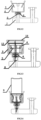
- the medication mixer includes a base 2, a medication mixing cup 3, a rubber plug 6, a medication mixing passage 7, a membrane 8 and an infusion passage, wherein the medication mixing cup 3 consists of a cup wall 3-1 and a cup bottom 3-2; the base 2, the medication mixing cup 3, the membrane 8 and the medication mixing passage 7 integrally form the body structure of the medication mixer.
- the rubber plug 6 is placed in the medication mixing passage 7, and is located above the membrane 8.
- the medication mixer further includes a cross needle 5, located in the medication mixing cup 3.
- the cross needle 5 includes a needle plate 5-1, an upper needle 5-2, a lower needle 5-3 and a needle point 5-5, wherein the upper needle 5-2 is integrated with the lower needle 5-3, the needle plate 5-1 combines the upper needle 5-2 with the lower needle 5-3, and the heads of the upper needle 5-2 and the lower needle 5-3 are provided with the needle points 5-5.
- the side hole 5-4 of the hollow passage of the upper needle 5-2 may be arranged on the side wall of the point of the upper needle 5-2, as shown in Figures 5,6 ; similarly, the side hole 5-4 of the hollow passage of the lower needle 5-3 is arranged on the side wall of the point of the lower needle 5-3 (not shown).
- Such an arrangement is to avoid plenty of chippings caused by an edge of the side hole 5-4 directly cutting a rubber plug or a bottle plug when the rubber plug 6 or the bottle plug is pierced by the upper needle 5-2 and the lower needle 5-3.
- a layer of elastic shrink film is coated on the upper needle 5-2, and is compressed after being pierced, stacking around a piercing hole, as shown in Figure 8 , thereby effectively preventing the liquid medication from leaking out along a gap of the piercing hole.
- the lower needle 5-3 is similarly coated with a layer of elastic shrink film, so as to solve the problem of leakage of the liquid medication along the gap of the piercing hole.
- the medication mixing passage 7 penetrates through the base 2, and upwards extends through the cup bottom 3-2 of the medication mixing cup 3.
- the membrane 8 functions to avoid the direct contact of the liquid medication with the rubber plug 6, so as to ensure the complete sealing before use.
- the membrane may be located at any position in the medication mixing passage 7 below the rubber plug 6. However, if the position of the membrane 8 is too low, the lower needle 5-3 of the cross needle 5 is too long, so preferably, the membrane 8 is located below the rubber plug 6 and clings to the lower surface of the rubber plug 6.
- the rubber plug 6 is placed in the medication mixing passage 7 and above the membrane 8.
- the rubber plug 6 functions to ensure that the liquid medication does not ooze from the medication mixing passage 7 after flowing out of the gap between the membrane 8 and the outer wall of the lower needle 5-3 after the rubber plug 6 and the membrane 8 are pierced by the lower needle 5-3. That is, the outer diameter of the rubber plug 6 is matched with the inner diameter of the medication mixing passage 7, such that the rubber plug 6 is closely contacted with the medication mixing passage 7.
- the upper surface of the rubber plug 6 is substantially flushed with or slightly higher than the upper surface of the cup bottom 3-2.
- the lower surface of the elastic clamping base 4 as shown in Figure 3 presses the upper surface of the rubber plug 6.
- the membrane 8 is located below the rubber plug 6 and clings to the lower surface of the rubber plug 6, as shown in Figure 1 , which may prevent the liquid medication from seeping into the medication mixing passage 7 after the lower needle 5-3 pierces the membrane 8.
- a relatively thin piercing region 6-1 defined by the convex ring 6-2 or the concave groove 6-3 is arranged on the surface of the rubber plug 6 as shown in Figure 2 .
- the concave groove 6-3 or the convex ring 6-2 is arranged on the upper surface of the membrane 8.
- the convex ring 6-2 or the concave groove 6-3 on the rubber plug 6 is tabled with the concave groove 6-3 or the convex ring 6-2 on the membrane 8, thereby better preventing the leakage of the liquid medication.
- the convex ring may also be 6-3, and the concave groove may be 6-2.
- the rubber plug 6 and the membrane 8 provided with the concave groove 6-3 or the convex ring 6-2 which are tabled with each other can completely avoid the leakage of the liquid medication after the medication mixing.
- the lower surface of the needle plate 5-1 surrounds the root of the lower needle 5-3, and is provided with a circle of annular protrusion. After the cross needle 5 with the clamping base is mounted in the medication mixing cup, the annular protrusion of the needle plate 5-1 presses against the rubber plug strongly, so as to realize better sealing.
- the infusion passage 11 as shown in Figure 11 can be integrated with the above-mentioned medication mixer body, and is arranged on the base 2 parallel with the medication mixer, as shown in Figure 1 .
- Another infusion port can be used when the soft bag is made.
- the infusion passage can be independently welded on the soft intravenous bag 1 by another base 2, at the same side as the medication mixer or the side opposite to the medication mixer, or other portions of the soft intravenous bag 1, which is obvious for persons skilled in the art.
- the medication mixer further includes an elastic clamping base 4, preferable, an independent elastic clamping base 4 as shown in Figure 3 .
- the cross needle 5 is placed between the elastic clamping jaw 4-1 and the bottom plate 4-5.
- the elastic clamping base 4 includes one clamping ring 4-6, the lower side of which is provided with the elastic clamping jaw 4-1.
- the upper ends of the elastic clamping jaw 4-1 are arranged uniformly and fixed along the clamping ring 4-6, and the lower ends of the elastic clamping jaw 4-1 are free ends.
- the elastic clamping jaw 4-1 inclines towards the center of the medication mixing cup 3 from the fixed upper ends to the free ends.
- the elastic clamping base has a bottom plate 4-5, a supporting column 4-4, a clamping ring 4-6 and an elastic clamping jaw 4-1 which are integrally formed.
- the supporting column 4-4 is arranged at the periphery of the bottom plate 4-5, for supporting and fixing the clamping ring 4-6.
- the bottom plate 4-5 is provided with a central hole 4-3, and the lower needle 5-3 penetrates through the central hole 4-3, thereby positioning the cross needle.
- a circle of annular protrusion 4-2 is arranged around the central hole 4-3; the region defined by the annular protrusion 4-2 is completely superimposed with the central hole 4-3, and is axially arranged with the medication mixing passage 7; the bottom plate 4-5 clings to the cup bottom 3-2 by the annular protrusion 4-2.
- the needle plate 5-1 of the cross needle 5 as shown in Figures 4-8 is mounted below the elastic clamping jaw 4-1 in the medication mixing cup 3 and above the bottom plate 4-5.
- the cross needle 5 includes the hollow upper needle 5-2 and lower needle 5-3 which are integrated as well as a needle plate 5-1 for integrating the upper needle 5-2 and the lower needle 5-3, and the heads of the upper needle 5-2 and the lower needle 5-3 are provided with needle points 5-5.
- the medication mixing cup 3 is integrated with the base 2
- the elastic clamping base 4 is placed in the medication mixing cup 3
- the cross needle 5 is clamped in the elastic clamping base 4.
- the cup wall is provided with the limit structure (not shown), the cross needle 5 with the clamping base is mounted in the medication mixing cup 3 and is limited by the limit structure.
- the limit structure not shown
- the cross needle 5 with the clamping base is mounted in the medication mixing cup 3 and is limited by the limit structure.
- the cross needle is completely limited by the limit structure.
- the elastic clamping base 4 is placed in the medication mixing cup 3, and then is limited by the limit structure (not shown) on the inner wall of the cup wall 3-1, thereby preventing the elastic clamping base 4 from sliding out of the medication mixing cup 3 after put in place.
- the position of limiting the elastic clamping base 4 makes the bottom of the elastic clamping base 4 contact with the cup bottom 3-2 of the medication mixing cup 3.
- the annular protrusion 4-2 at the bottom of the elastic clamping base 4 presses against the rubber plug 6.
- the needle plate 5-1 of the cross needle 5 mounted in the elastic clamping base 4 is located between the elastic clamping jaw 4-1 and the bottom plate 4-5, and afterwards, the lower needle 5-3 does not pierce the rubber plug 6.
- the lower needle 5-3 partially pierces the rubber plug 6, or as shown in Figure 9 , the lower needle 5-3 completely pierces the rubber plug 6, or more preferably, a small hole is arranged at the center of the rubber plug 6 in advance, so as to form an annular rubber plug 6, and the lower needle 5-3 pierces the rubber plug 6 via the small hole, which are all feasible.
- the diameter of the small central hole of the rubber plug 6 is less than that of the lower needle 5-3, such that the lower needle 5-3 does not cut the rubber plug 6 after the lower needle 5-3 is inserted in the small hole of the rubber plug 6 and penetrates through the rubber plug 6, thereby effectively avoiding the pollution of the chippings to the liquid medication when the lower needle 5-3 pierces the rubber plug 6.
- the diameter of the small hole is less than the outer diameter of the lower needle 5-3, the rubber plug 6 still clings to the lower needle 5-3, thereby avoiding the liquid leakage.
- the cross needle 5 is just placed in the medication mixing cup 3, and does not pierce the membrane 8.
- the rubber plug 6 can be not pierced, or partially pierced, or completely pierced as long as the membrane 8 is not pierced, and the use of the medication mixer is not affected.
- a partition plate 12 is taken off and the penicillin bottle 9 is inserted, as shown in Figure 14 , the bottle neck of the penicillin bottle 9 is pushed down below the elastic clamping jaw 4-1.
- the upper needle 5-2 and the lower needle 5-3 of the cross needle 5 respectively pierce the rubber plug 6, the membrane 8 and the bottle plug of the penicillin bottle 9.
- the cross needle 5 is completely limited by the limit protrusion on the inner wall of the medication mixing cup 3, that is by the elastic clamping jaw 4-1.
- the bottle neck of the penicillin bottle 9 is clamped by the elastic clamping jaw 4-1 and cannot withdraw.
- the penicillin bottle 9 is inserted in the medication mixing cup 3, and the bottle cap of the penicillin bottle 9 is pressed in the elastic clamping base 4, such that the free end of the elastic clamping jaw 4-1 is located at the bottle neck of the penicillin bottle 9 and is clamped at the bottle neck, thereby clamping the penicillin bottle 9 and preventing the penicillin bottle 9 from withdrawing from the medication mixing cup 3.
- the bottle cap of the penicillin bottle 9 is pierced by the upper needle 5-2, and the bottle cap presses the needle plate 5-1 downwards, thereby pushing the lower needle 5-3 to pierce the rubber plug 6 and then the membrane 8, such that the medication mixing passage 7 is communicated with the penicillin bottle 9 via the cross needle 5.
- the clamping ring 4-6 of the elastic clamping base 4 has an inner diameter substantially the same as or slightly greater than the outer diameter of the penicillin bottle 9.
- the cap thickness of the penicillin bottle 9 shall be substantially the same as the distance of the free ends of the elastic clamping jaw 4-1 to the bottom plate 4-5, such that the penicillin bottle 9 is just clamped between the free ends of the elastic clamping jaw 4-1 and the bottom plate 4-5 through the bottle cap, and cannot move up and down.
- the distance of the free end of the elastic clamping jaw 4-1 to the bottle plate 4-5 is slightly greater than the thickness of the bottle cap, which does not influence the butt joint and fixation of the penicillin bottle 9.
- the elastic clamping base 4 and the medication mixing cup 3 are assembled, as shown in Figure 9 , there is one preferable solution that the upper surface of the rubber plug 6 is substantially flushed with or slightly higher than the upper surface of the cup bottom 3-2. As such, the lower surface of the elastic clamping base 4 as shown in Figure 3 presses against the upper surface of the rubber plug 6.
- the elastic clamping base 4 as shown in Figure 3 is placed in the medication mixing cup 3.
- the cross needle 5 as shown in Figures 4-8 is placed in the elastic clamping base 4, thereby forming the medication mixer as shown in Figure 9 .
- the cover plate 12 is placed at the cup opening of the medication mixing cup 3, and then the medication mixing cup 3 is covered and sealed by the sealing membrane 13.
- the medication mixer together with the infusion passage 11 arranged on the base 2 parallel with the medication mixer, forms the dual hard ports.
- the medication mixer is connected with the soft intravenous bag 1 in a welding way, to form the soft intravenous bag 1 with the medication mixer, as shown in Figure 16 .
- the medication mixer is jointed with the soft intravenous bag 1 by the base 2.
- the infusion passage 11 can be arranged on the base 2, parallel with the medication mixer, as shown in Figure 1 .
- the infusion passage 11 can be independently welded on the soft intravenous bag 1 by another base 2, at the same side as the medication mixer or the side opposite to the medication mixer, or other portions of the soft intravenous bag 1, which is obvious for persons skilled in the art.
- the medication mixing cup 3 needs to be sealed.
- the easy-to-tear film is usually used to seal the medication mixing cup 3, preferably, a pp easy-to-tear film, and more preferably, a breathable pp easy-to-tear film.
- the easy-to-tear film is directly pressed at the cup opening of the medication mixing cup 3, and is directly torn when the medication mixing cup 3 is used.
- the soft intravenous bag 1 Since the soft intravenous bag 1 is sealed and then sterilized at a high temperature after filled, if the medication mixing cup 3 is not sealed, the sterilized soft intravenous bag 1 with the medication mixer is inevitably polluted during transportation and use and its sterility cannot be guaranteed due to the cross needle 5 for piercing in the medication mixing cup 3 still exposing in the external environment.
- the cup body of the medication mixing cup 3 made of the medical polymer material and the easy-to-tear film of the sealed medication mixing cup 3 will soften and shrink; there is a relatively large pressure difference between the inside and outside of the sealed medication mixing cup 3; under the high pressure, the medication mixing cup 3 and the easy-to-tear film will be deformed, and be crushed after cooled, thereby damaging the structure of the medication mixing cup, and causing the medication mixer not to be used.
- the reinforcing ribs 3-3 are arranged on the cup wall 3-1 of the medication mixing cup 3, preferably, at the lower half portion of the cup wall 3-1, as shown in Figure 17 .
- the reinforcing ribs 3-3 may be protruding vertical bars or horizontal bars which are integrated with the medication mixing cup 3 and uniformly arranged at the inner side and/or outer side of the cup wall 3-1, or may have a criss-crossed net structure.
- the vertical bars are uniformly arranged at the lower half portion of the inner side of the cup wall 3-1; more preferably, the protruding vertical bars extend to the cup bottom 3-2 from the lower half portion of the inner side of the cup wall 3-1, and most preferably, the thickness of the vertical protrusion continuously increases gradually and smoothly from top to bottom.
- the arrangement of the reinforcing ribs 3-3 on the cup wall 3-1 may substantially solve the problem that the medication mixing cup 3 is pressed and deformed during the sterilization. However, there still exists the problem that the sealing membrane 13 of the sealed medication mixing cup 3 is compressed and deformed when sterilized.
- the cover plate 12 as shown in Figure 18 is further arranged at the cup opening of the medication mixing cup 3, and is covered by the sealing membrane 13, such that the cover plate 12 effectively supports the sealing membrane 13, so as to prevent the sealing membrane 13 from being compressed and deformed in sterilization.
- the inner stepwise edge is arranged at the cup opening along the cup wall 3-1, and the cover plate 12 is placed on the inner stepwise edge, such that the upper surface of the cover plate 12 arranged at the cup opening is flushed with or slightly lower than the cup opening, which does not influence the sealing process of press welding the sealing membrane 13 on the upper end surface of the cup wall 3-1.
- the cover plate 12 is arranged coaxially with the cross needle 5, and the needle point 5-5 of the upper needle 5-2 is dead against the center of the cover plate 12.
- the cover plate 12 is preferably designed into a polygon with a hole in the center.
- the experiment shows that after the pressure balancing means is adopted, such a preferable design can balance the pressure inside and outside the medication mixing cup 3 more rapidly, thereby functioning very well in the moist heat sterilization process---the sealing membrane 13 is smooth as before, and the medication mixing cup 3 is not deformed.
- the polygonal cover plate 12 with a central hole can increase the gas exchanging speed below and above the cover plate 12, and balance the air pressure in the medication mixing cup 3 more rapidly, as well as the air pressure outside and inside the medication mixing cup 3.
- the medication preparation and addition can be performed safely, conveniently and rapidly, which completely solves the problem of secondary pollution at the stage of the medication preparation.
- the infusion can be traced since the penicillin bottle 9 cannot be taken out non-destructively after connected and fixed onto the medication mixing cup 3 and clamped by the elastic clamping jaw 4-1. That is, from the medication preparation to the completion of infusion, until the recovery, the medication added and injected can be traced.
- the above-mentioned medication mixer may have some inconveniences since the medication filled in the penicillin bottle 9 must be brought to the impatient ward, then the penicillin bottle 9 is abutted with the medication mixer, and the medication can be used after preparation in the ward.
- the easy-breaking handle 10 is additionally arranged, as shown in Figure 15 .
- the easy-breaking handle 10 is arranged at the lower end of the medication mixing passage 7. As shown in Figure 15 , having abutted with the elastic clamping base 4 in the medication mixing cup 3 and is pierced, the penicillin bottle 9 is brought to the ward. Before infusion, the easy-breaking handle 10 is broken, the medication mixing passage 7 is broken through, and the on-the-spot medication preparation and use can be realized.
- the base 2 is designed into a shape of a dumbbell or ship, as shown in Figure 1 , and the lower ends of the medication mixing passage 7 and the infusion passage 11 are flushed with the lower end of the base 2.
- the welding lines are uniformly distributed on the side wall all around the base 2, which may ensure that the base 2 may be well fused and welded with the soft intravenous bag 1 even at a relatively low temperature in the welding process of the soft intravenous bag 1.
- the streamlined base 2 of a shape of ship or dumbbell not only improves mechanical property of welding, but also makes the combination of the dual hard ports with the soft intravenous bag 1 more smooth without a sharp angle, and does not tend to damage the soft bag.
- the soft intravenous bag 1 is made of the widely used non-PVC officinal compounding velamen, including three or five layers.
- the medication mixer is made of the medical polypropylene material having good compatibility with the non-PVC material of the soft intravenous bag 1.
- the base 2, the medication mixing cup 3 and the cover plate 12 are preferably made of the polypropylene R530C material; however, the cross needle 5 and the clamping body are preferably made of the P17 material in the pp material system in view of its piercing property and mechanical characteristics.
- the cross needle 5, the limit protrusion and the limit structure are made of the polypropylene material, preferably, the polypropylene P17 material.
- the terminal sterilization after the sealed medication mixer is welded on the soft bag.
- the terminal sterilization must be performed to all the medication packages before the filling and delivery.
- the large volume infusion is very sensitive to the cost. Therefore, the terminal sterilization in the large volume infusion may only adopt the moist heat sterilization process with a low cost and high efficiency, which is usually conducted at a high temperature of 115-121 degrees Celsius, under the steam with a pressure of 0.15 MPa, for 30-15 minutes.
- the medication mixer and the soft intravenous bag 1 are made of the polypropylene material withstanding the high temperature of 120 degrees Celsius, at such a high temperature, the sealed medication mixer will degrade in mechanical characteristics, and tends to deform under the intensity of pressure of 0.15 MPa; however, the sealing membrane 13 will also be deformed and wrinkled at this temperature and intensity of pressure, losing the sealing effect.
- the reinforcing ribs 3-3 are arranged at the lower half portion of the cup body.
- the reinforcing ribs 3-3 are arranged at the cup wall 3-1 of the medication mixing cup 3, preferably, at the lower half portion of the cup wall 3-1.
- the reinforcing ribs 3-3 may be protruding vertical bars or horizontal bars which are integrated with the medication mixing cup 3 and uniformly arranged at the inner side and/or outer side of the cup wall 3-1, or may have a criss-crossed net structure.
- the vertical bars are uniformly arranged at the lower half portion of the inner side of the cup wall 3-1; more preferably, the protruding vertical bars extend to the cup bottom 3-2 from the lower half portion of the inner side of the cup wall 3-1, and most preferably, the thickness of the vertical protrusion continuously increases gradually and smoothly from top to bottom.
- the medication mixing cup 3 with the reinforcing ribs 3-3 improves the mechanical pressure resistance of the cup body to a considerable extent.
- the medication mixing cup 3 without the reinforcing ribs 3-3 is compressed into a square from the initial circular shape after the moist heat sterilization is performed, and cannot be used any more.
- the circular medication mixing cup body is slightly compressed, and can be continue to use normally.
- the sealing membrane 13 is only a very thin easy-to-tear film, for sealing the medication mixing cup 3 and being convenient to tear out in use.
- the sealing membrane 13 is thinner than the cup body of the medication mixing cup 3 since the sealing membrane 13 itself is only a layer of thin film with a thickness of micron dimension, and cannot withstand the intensity of pressure of 0.15 MPa in the moist heat sterilization process.
- cover plate 12 as shown in Figure 13 is arranged under the sealing membrane 13, and is covered by the sealing membrane 13, such that the cover plate 12 effectively supports the sealing membrane 13, so as to prevent the sealing membrane 13 from being compressed and deformed in sterilization.
- the cover plate 12 is placed on an inner stepwise edge of the cup opening of the medication mixing cup 3, such that the upper surface of the cover plate 12 arranged at the cup opening is flushed with or slightly lower than the cup opening.
- Such an arrangement of the cover plate 12 does not influence the sealing process of press welding the sealing membrane 13 on the upper end surface of the cup wall 3-1.
- the cover plate 12 has a circular shape substantially matched with the shape of the cup opening of the medication mixing cup 3.
- the cover plate 12 has a shape in cross section of polygon, for example, pentagon, hexagon, octagon and dodecagon.
- the polygonal cover plate 12 is conveniently taken out in use; its another unexpected effect will be mentioned in the following.
- the cover plate 12 is arranged coaxially with the cross needle 5, with the needle point 5-5 of the upper needle 5-2 dead against the center of the cover plate 12, for supporting the cover plate 12. More preferably, one through hole 12-1 is arranged in the center of the cover plate 12 which has an inner diameter less than an outer diameter of the upper needle 5-2.
- the needle point 5-5 of the upper needle 5-2 is partially located in the through hole 12-1, but cannot penetrate therethrough. That is, the needle point 5-5 of the upper needle 5-2 is embedded in the through hole 12-1 of the cover plate 12, thereby better supporting the cover plate 12 by the upper needle 5-2.
- the cover plate 12 is reinforced other than the design of supporting the cover plate 12 by the upper needle 5-2.
- the radial and annular reinforce ribs 12-2 as shown in Figure 18 enhance the mechanical strength of the cover plate 12.
- the sealing membrane 13 press welded on the upper end of the cup opening is tightly stuck on the upper surface of the cover plate 12, such that the sealing membrane 13 does not need to withstand a high pressure, which greatly buffer the deformation and wrinkle of the sealing membrane 13.
- the wrinkle since the sealing membrane 13 is too thin, the wrinkle will be caused even by a slight pressure, which seriously influences the vision effect of the product.
- a layer of thin metal film is plated on the upper surface of the sealing membrane 13 may effectively alleviate the problem of wrinkle of the sealing membrane.
- the sealed medication mixer with such an arrangement withstands the high temperature and high pressure in the moist heat sterilization process and can be used normally, the product appearance cannot be kept in a good state. In view of the infusion product, it is not qualified.
- the above-mentioned design for the structure of the medication mixer can only ensure the use function. In order to completely solve the problem of terminal sterilization of the sealed medication mixer, it needs to fundamentally solve the balance of air pressure inside and outside in the moist heat sterilization of the sealed medication mixing cup.
- the liquid is rapidly vaporized at a high temperature, thereby balancing the pressure inside and outside the cup body rapidly.
- the thermal capacity is relatively small, to saturate the liquid with a relatively high steam pressure.
- the prefilled liquid is water.
- V0 n ⁇ M/ ⁇ , wherein M is a mole mass of the liquid/water, and ⁇ is a density of the liquid/water.
- the pressure inside and outside in the terminal sterilization of the sealed medication mixer can be well balanced.
- one more preferably solution is that we have specially studied the breathable sealing membrane 13 based on the pp material system, which ensures sufficient gas exchange of the breathable sealing membrane 13 with outside after the vaporization of liquid, so there is no residual liquid in the medication mixing cup 3 after the sterilization.
- the air permeability of the breathable sealing membrane 13 is, most preferably, 5%-35%.
- the medication mixer sealed by our breathable sealing membrane 13 subsequent to the moist heat high temperature sterilization, the medication mixing cup 3 is not deformed, and the sealing membrane 13 is smooth as before, without any wrinkle.
- the cup opening of the medication mixing cup 3 is sealed usually by the sealing membrane 13 or the easy-to-tear sealing membrane in a press welding way; or one cover plate 12 is placed at the cup opening, and then the sealing membrane 13 is placed thereon.
- the sealed medication mixing cup 3 is welded on the soft intravenous bag 1, so as to form the soft intravenous bag 1 with the medication mixer, as shown in Figure 16 .
- the mixer is ready for medical workers to use.
- the elastic clamping base 4 in the first embodiment is substituted with the limit protrusion direclty fixed on the inner wall of the medication mixing cup 3.
- the limit protrusion (not shown) is arranged on the inner wall of the cup wall 3-1, and the cross needle 5 with the clamping base is mounted in the medication mixing cup 3 and is limited by the limit protrusion.
- the cross needle 5 is completely limited by the limit protrusion.
- the elastic clamping jaw 4-1 is used; more preferably, the elastic clamping jaw 4-1 as the limit protrusion is integrated with the medication mixing cup 3.
- the upper ends of the elastic clamping jaw 4-1 are arranged evenly and fixed along the periphery of the inner wall of the cup wall 3-1.
- the lower ends of the elastic clamping jaw are free ends, and the elastic clamping jaw 4-1 inclines towards the center of the medication mixing cup 3 from the fixed upper ends to the free ends, as shown in Figure 12 .
- FIG. 13 shows the state that the cross needle 5 has pierced the rubber plug 6 but does not pierce the membrane 8.
- the distance of the upper surface of the cup bottom 3-2 to the lower surface of the membrane 8 is less than the length of the lower needle 5-3.
- the cross needle 5 is directed fixed with the elastic clamping base 4, and preferably, the cross needle 5 is integrated with the elastic clamping base 4.
- the elastic clamping base 4 in the third embodiment includes one clamping ring 4-6 provided with an elastic clamping jaw 4-1 at the lower side.
- the upper ends of the elastic clamping jaw 4-1 are arranged uniformly and fixed along the clamping ring 4-6, and the lower ends of the elastic clamping jaw 4-1 are free ends.
- the elastic clamping jaw 4-1 inclines towards the center of the medication mixing cup 3 from the fixed upper ends to the free ends.
- the elastic clamping base 4 has a bottom plate 4-5, a supporting column 4-4, a clamping ring 4-6 and an elastic clamping jaw 4-1 which are integrally formed.
- the supporting column 4-4 is arranged at the periphery of the bottom plate 4-5, for supporting and fixing the clamping ring 4-6.
- the difference between the first embodiment and the third embodiment is that the central hole 4-3 on the bottom plate 4-5 is omitted, and the cross needle 5 is integrally fixed on the bottom plate 4-5 directly.
- the structures of the upper needle 5-2 and the lower needle 5-3 are the same as those as shown in Figures 4-8 .
- the hollow passages of the upper needle 5-2 and the lower needle 5-3 penetrate through the center of the bottom plate 4-5 of the elastic clamping base 4 and are communicated with each other.
- a circle of annular protrusion 4-2 is arranged at the root of the lower needle 5-3. After the elastic clamping base 4 is mounted in the medication mixing cup 3, the annular protrusion 4-2 on the elastic clamping base 4 presses against the rubber plug 6.
- the elastic clamping base 4 is mounted in the medication mixing cup 3 and is limited by the cup wall 3-1 and cannot be taken out when pushed to the cup bottom 3-2.
- the lower needle 5-3 pierces both the rubber plug 6 and the membrane 8.
- the supporting column 4-3, the clamping ring 4-6 and the elastic clamping jaw 4-1 are integrally arranged on the needle plate 5-1, and the supporting column 4-3 is arranged at a periphery of the needle plate 5-1 to support and fix the clamping ring 4-6.
- the upper ends of the elastic clamping jaw 4-1 are arranged evenly and fixed along the clamping ring.
- the lower ends of the elastic clamping jaw are free ends, and the elastic clamping jaw 4-1 inclines towards the center of the medication mixing cup from the fixed upper ends to the free lower ends.
- the limit protrusion is arranged on an inner wall of the cup wall. After the cross needle is mounted in the medication mixing cup, the needle plate is limited between the limit protrusion and the cup bottom by the limit protrusion, and cannot be taken out.
- the limit protrusion herein is preferably an elastic clamping jaw.
- the cross needle 5 with a clamping base is placed in the medication mixing cup 3. As shown in Figure 20 , the cross needle 5 with the clamping base placed in the medication mixing cup 3 is pushed to the cup bottom 3-2, thereby piercing the rubber plug 6 and the membrane 8.
Claims (11)
- Mélangeur de médicament, comprenant une base (2), un passage de mélange de médicament (7) et un godet de mélange de médicament (3) qui sont formés d'un seul tenant, ainsi qu'une aiguille croisée (5), dans lequel le godet de mélange de médicament est constitué d'une paroi de godet (3-1) et d'un fond de godet (3-2) ;l'aiguille croisée est constituée d'une plaque à aiguille intégrée (5-1), ainsi que d'une aiguille supérieure (5-2) et d'une aiguille inférieure (5-3) avec des passages creux qui communiquent les uns avec les autres ;dans lequel,l'extrémité inférieure du passage de mélange de médicament (7) pénètre à travers la base (2) et son extrémité supérieure à travers le fond de godet, une membrane de séparation (8) est agencée dans le passage de mélange de médicament (7) entre la base (2) et le fond de godet (3-2), et un bouchon en caoutchouc (6) est agencé dans le passage de mélange de médicament (7) entre la membrane de séparation (8) et le fond de godet (3-2) ;la distance entre la surface supérieure du fond de godet (3-2) et la surface inférieure de la membrane de séparation (8) est inférieure à la longueur de l'aiguille inférieure (5-3) ;le mélangeur de médicament comprend en outre une membrane d'étanchéité (13) qui est reliée par soudage par pression à une embouchure du godet de mélange de médicament, de manière à sceller le godet de mélange de médicament ;la membrane d'étanchéité (13) est une membrane facilement déchirable qui peut maintenir encore sensiblement lisse après une stérilisation terminale par la chaleur humide ;caractérisé en ce que,comprenant en outre une base de serrage élastique (4) comportant une bague de serrage (4-6) munie d'une mâchoire de serrage élastique (4-1) au niveau du côté inférieur, les extrémités supérieures de la mâchoire de serrage élastique (4-1) sont agencées de manière uniforme et fixe le long de la bague de serrage, et les extrémités inférieures de la mâchoire de serrage élastique sont des extrémités libres, et la mâchoire de serrage élastique (4-1) s'incline vers le centre du godet de mélange de médicament depuis ses extrémités supérieures fixes jusqu'à ses extrémités inférieures libres ;la plaque à aiguille (5) est montée sous la mâchoire de serrage élastique (4-1) dans le godet de mélange de médicament ;une structure de limitation est agencée sur un côté intérieur de la paroi de godet, et la base de serrage élastique (4) est montée à l'intérieur du godet de mélange de médicament (3) et est limitée par la structure de limitation ;le godet de mélange de médicament (3) est prérempli d'une certaine quantité de liquide avant d'être scellé par la membrane d'étanchéité (13), pour équilibrer sensiblement la pression d'air à l'intérieur et à l'extérieur du godet de mélange de médicament ;le liquide peut être rapidement vaporisé dans un environnement de stérilisation par la chaleur humide.
- Mélangeur de médicament selon la revendication 1, caractérisé en ce que,la base de serrage élastique (4) comporte une plaque de fond (4-5), une colonne de support (4-4), une bague de serrage (4-6) et une mâchoire de serrage élastique (4-1), qui sont formées d'un seul tenant, dans laquelle la colonne de support (4-4) est agencée sur une périphérie de la plaque de fond (4-5), de manière à supporter et à fixer la bague de serrage (4-6) ;un trou central est agencé sur la plaque de fond (4-5), l'aiguille inférieure pénètre à travers le trou central, ce qui permet de positionner l'aiguille croisée ;la plaque à aiguille (5-1) est située entre la plaque de fond (4-5) et le mâchoire de serrage élastique (4-1).
- Mélangeur de médicament ayant une structure de renfort, comprenant le mélangeur de médicament selon l'une quelconque des revendications 1 à 2 ;des nervures de renfort (3-3) sont agencées sur la paroi (3-1) du godet de mélange de médicament (3), de manière à améliorer la résistance à la compression de la paroi de godet ;les nervures de renfort (3-3) sont agencées intégralement sur un côté intérieur de la paroi de godet (3-1) dans une direction ascendante et descendante et/ou une direction horizontale.
- Mélangeur de médicament selon la revendication 3, caractérisé en ce que,une zone à perforation est formée dans la zone centrale du bouchon en caoutchouc (6), et est plus mince qu'une zone marginale ;une saillie annulaire est agencée dans la zone centrale de la surface inférieure de la plaque à aiguille (5-1), et la zone à perforation est superposée à ou située dans la zone limitée par la saillie annulaire.
- Mélangeur de médicament selon la revendication 3, caractérisé en ce que,le mélangeur de médicament comprend en outre une couvre-plaque (12) ; la couvre-plaque est située au niveau de l'embouchure du godet ;un bord intérieur étagé est agencé le long de la paroi de godet au niveau de l'embouchure du godet, et la couvre-plaque est posée sur le bord intérieur ;la surface supérieure de la couvre-plaque (12) est au même niveau ou légèrement plus basse que l'embouchure du godet ;la membrane d'étanchéité (13) est pressée à chaud sur la surface d'extrémité supérieure de la paroi de godet, scellant ainsi l'embouchure du godet ;la couvre-plaque est polygonale, avec un trou (12-1) au centre, et la pointe de l'aiguille supérieure est située dans le trou et ne le traverse pas.
- Mélangeur de médicament selon l'une quelconque des revendications 3 à 5, caractérisé en ce que,la membrane d'étanchéité est une membrane respirante et facile à déchirer, avec une perméabilité à l'air de 5% à 35% ;un film métallique est plaqué sur une surface supérieure de la membrane d'étanchéité.
- Mélangeur de médicament selon la revendication 3, caractérisé en ce que, l'extrémité inférieure du passage de mélange de médicament est munie d'une poignée facile à briser pour sceller l'extrémité inférieure du passage de mélange de médicament.
- Mélangeur de médicament selon la revendication 3, caractérisé en ce que,un bague convexe ou une rainure concave est agencée sur la surface supérieure de la membrane de séparation (8), et une rainure concave ou un bague convexe est agencée de manière correspondante sur la surface inférieure du bouchon en caoutchouc (6) ;la membrane de séparation (8) est posée sur le bouchon en caoutchouc (6) au moyen de la bague convexe ou de la rainure concave.
- Mélangeur de médicament selon la revendication 3, caractérisé en ce que,une sortie du passage creux de l'aiguille supérieure est agencée sur la paroi latérale de la pointe de l'aiguille supérieure (5-2) ;
et/ou,une sortie du passage creux de l'aiguille inférieure est agencée sur la paroi latérale de la pointe de l'aiguille inférieure (5-3) ;l'aiguille supérieure est revêtue d'une couche de film rétractable élastique ;
et/ou,l'aiguille inférieure est revêtue d'une couche de film rétractable élastique. - Doubles orifices durs avec un mélangeur de médicament, comprenant le mélangeur de médicament selon l'une quelconque des revendications 1 à 9, caractérisé en ce que, un passage de perfusion est agencé sur la base du mélangeur de médicament, sur le côté opposé au passage de mélange de médicament ; et
Les orifices sont agencés sur le passage de perfusion. - Poche de perfusion souple, comprenant le mélangeur de médicament selon l'une quelconque des revendications 1 à 9 ;ou comprenant les doubles orifices durs selon la revendication 10 ;le mélangeur de médicament ou les doubles orifices durs sont reliés à la poche souple par la base ;comprenant en outre un orifice de perfusion qui est agencé sur la poche de perfusion souple du même côté que le mélangeur de médicament, ou agencé sur la poche de perfusion souple du côté opposé au mélangeur de médicament.
Applications Claiming Priority (4)
| Application Number | Priority Date | Filing Date | Title |
|---|---|---|---|
| CN201510780465.8A CN105232329B (zh) | 2015-11-13 | 2015-11-13 | 混药器、硬双接口及输液软袋 |
| CN201510781507.XA CN105232331B (zh) | 2015-11-13 | 2015-11-13 | 混药器、硬双接口及输液软袋 |
| CN201510781506.5A CN105232330B (zh) | 2015-11-13 | 2015-11-13 | 混药器、硬双接口及输液软袋 |
| PCT/CN2016/105564 WO2017080522A1 (fr) | 2015-11-13 | 2016-11-13 | Mélangeur de médicament, élément dur à deux orifices, et poche d'infusion souple |
Publications (4)
| Publication Number | Publication Date |
|---|---|
| EP3375427A1 EP3375427A1 (fr) | 2018-09-19 |
| EP3375427A4 EP3375427A4 (fr) | 2019-01-02 |
| EP3375427B1 true EP3375427B1 (fr) | 2023-06-21 |
| EP3375427C0 EP3375427C0 (fr) | 2023-06-21 |
Family
ID=58694545
Family Applications (1)
| Application Number | Title | Priority Date | Filing Date |
|---|---|---|---|
| EP16863698.3A Active EP3375427B1 (fr) | 2015-11-13 | 2016-11-13 | Mélangeur de médicament, élément dur à deux orifices, et poche d'infusion souple |
Country Status (6)
| Country | Link |
|---|---|
| US (1) | US20200253827A1 (fr) |
| EP (1) | EP3375427B1 (fr) |
| JP (1) | JP2018535071A (fr) |
| KR (1) | KR102119990B1 (fr) |
| CA (1) | CA3004927C (fr) |
| WO (1) | WO2017080522A1 (fr) |
Families Citing this family (12)
| Publication number | Priority date | Publication date | Assignee | Title |
|---|---|---|---|---|
| EP3760180A3 (fr) | 2009-07-29 | 2021-01-20 | ICU Medical, Inc. | Methode du transfert de fluides |
| MX352572B (es) | 2011-12-22 | 2017-11-29 | Icu Medical Inc | Dispositivos de transferencia de fluidos y metodos de uso. |
| WO2015077184A1 (fr) | 2013-11-25 | 2015-05-28 | Icu Medical, Inc. | Procédés et système pour remplir des sacs pour perfusion intraveineuse d'un fluide thérapeutique |
| AU2016365335B2 (en) | 2015-12-04 | 2021-10-21 | Icu Medical, Inc. | Systems methods and components for transferring medical fluids |
| HUE054412T2 (hu) | 2016-05-16 | 2021-09-28 | Haemonetics Corp | Tömítõ nélküli plazmapalack és felsõrész ugyanahhoz |
| US11648179B2 (en) | 2016-05-16 | 2023-05-16 | Haemonetics Corporation | Sealer-less plasma bottle and top for same |
| USD851745S1 (en) | 2016-07-19 | 2019-06-18 | Icu Medical, Inc. | Medical fluid transfer system |
| AU2017302557B2 (en) | 2016-07-25 | 2022-10-13 | Icu Medical, Inc. | Systems, methods, and components for trapping air bubbles in medical fluid transfer modules and systems |
| KR102171701B1 (ko) * | 2020-03-17 | 2020-10-29 | (주)메디라인액티브코리아 | 약물 혼합용 키트 및 이를 포함하는 밀봉팩 |
| US11590057B2 (en) | 2020-04-03 | 2023-02-28 | Icu Medical, Inc. | Systems, methods, and components for transferring medical fluids |
| WO2022076908A2 (fr) | 2020-10-09 | 2022-04-14 | Icu Medical, Inc. | Dispositif de transfert de fluide et son procédé d'utilisation |
| CN113150957A (zh) * | 2021-05-19 | 2021-07-23 | 上海履济技术服务中心 | 一种防病毒入侵瓶盖组合及其应用 |
Family Cites Families (33)
| Publication number | Priority date | Publication date | Assignee | Title |
|---|---|---|---|---|
| JP2605345Y2 (ja) * | 1992-05-01 | 2000-07-10 | 株式会社大塚製薬工場 | 薬剤容器 |
| JP3322450B2 (ja) * | 1993-08-31 | 2002-09-09 | テルモ株式会社 | 注入容器 |
| JP2901474B2 (ja) * | 1993-11-29 | 1999-06-07 | 川澄化学工業株式会社 | 医療用プラスチック容器の口部並びに医療用プラスチック容器の製造方法 |
| JPH08126683A (ja) * | 1994-10-31 | 1996-05-21 | Fujisawa Pharmaceut Co Ltd | 輸液用容器 |
| JPH10314273A (ja) * | 1997-05-19 | 1998-12-02 | Material Eng Tech Lab Inc | 医療用容器 |
| JP4048337B2 (ja) * | 1998-09-02 | 2008-02-20 | 株式会社大塚製薬工場 | 両頭針付き輸液容器 |
| US6022339A (en) * | 1998-09-15 | 2000-02-08 | Baxter International Inc. | Sliding reconstitution device for a diluent container |
| US20050137566A1 (en) * | 2003-12-23 | 2005-06-23 | Fowles Thomas A. | Sliding reconstitution device for a diluent container |
| JP4515626B2 (ja) * | 2000-12-08 | 2010-08-04 | ニプロ株式会社 | 液体移注具 |
| JP4758018B2 (ja) * | 2001-03-28 | 2011-08-24 | 株式会社大塚製薬工場 | 薬液容器 |
| CN2897247Y (zh) * | 2006-04-08 | 2007-05-09 | 浙江永宁制药厂 | 旋盖式无针配药稀释输液袋 |
| US7473246B2 (en) * | 2006-06-22 | 2009-01-06 | Baxter International Inc. | Medicant reconstitution container and system |
| CN202027918U (zh) * | 2011-01-31 | 2011-11-09 | 湖南乐福地医药包材科技有限公司 | 输液包装 |
| CN202036528U (zh) * | 2011-01-31 | 2011-11-16 | 湖南乐福地医药包材科技有限公司 | 硬双接口 |
| CN201987882U (zh) | 2011-03-01 | 2011-09-28 | 重庆莱美药业股份有限公司 | 一种用于塑料输液软袋的混药接口 |
| JP5889572B2 (ja) * | 2011-08-18 | 2016-03-22 | 内外化成株式会社 | 弾性栓体、医療用キャップおよびその製造方法 |
| WO2013067836A1 (fr) * | 2011-11-11 | 2013-05-16 | 重庆莱美药业股份有限公司 | Interface de mélange de médicament intégrée |
| CN102499888B (zh) * | 2011-11-11 | 2013-07-03 | 重庆莱美药业股份有限公司 | 一体成型的混药接口 |
| US20150157536A1 (en) * | 2012-02-13 | 2015-06-11 | Chongqing Lummy Pharmaceutical Co., Ltd. | Doser having two needles |
| WO2014103411A1 (fr) * | 2012-12-28 | 2014-07-03 | 味の素株式会社 | Récipient multi-chambres |
| CN203107704U (zh) * | 2013-02-25 | 2013-08-07 | 四川科伦药物研究有限公司 | 一种输液容器用密封盖 |
| CN203123029U (zh) * | 2013-04-12 | 2013-08-14 | 重庆莱美医疗器械有限公司 | 分接口混药嘴 |
| CN203123028U (zh) | 2013-04-12 | 2013-08-14 | 重庆莱美医疗器械有限公司 | 组合式混药接口 |
| CN203252919U (zh) * | 2013-05-21 | 2013-10-30 | 重庆莱美医疗器械有限公司 | 带混药杯的硬双接口 |
| CN203677543U (zh) * | 2013-12-31 | 2014-07-02 | 重庆莱美医疗器械有限公司 | 转笼式推进预装式双针硬双接口 |
| CN203954197U (zh) * | 2014-07-28 | 2014-11-26 | 冯邦玺 | 一次性吸、配药器 |
| CN105232330B (zh) * | 2015-11-13 | 2019-11-26 | 重庆莱美药业股份有限公司 | 混药器、硬双接口及输液软袋 |
| CN205359992U (zh) * | 2015-11-13 | 2016-07-06 | 重庆莱美药业股份有限公司 | 混药器、硬双接口及输液软袋 |
| CN205549013U (zh) * | 2015-11-13 | 2016-09-07 | 重庆莱美药业股份有限公司 | 混药器、硬双接口及输液软袋 |
| CN205339562U (zh) * | 2015-11-13 | 2016-06-29 | 重庆莱美药业股份有限公司 | 混药器、硬双接口及输液软袋 |
| CN105232329B (zh) * | 2015-11-13 | 2019-02-22 | 重庆莱美药业股份有限公司 | 混药器、硬双接口及输液软袋 |
| CN105232331B (zh) * | 2015-11-13 | 2019-01-08 | 重庆莱美药业股份有限公司 | 混药器、硬双接口及输液软袋 |
| CN205339561U (zh) * | 2015-11-13 | 2016-06-29 | 重庆莱美药业股份有限公司 | 混药器、硬双接口及输液软袋 |
-
2016
- 2016-11-13 EP EP16863698.3A patent/EP3375427B1/fr active Active
- 2016-11-13 CA CA3004927A patent/CA3004927C/fr active Active
- 2016-11-13 JP JP2018544393A patent/JP2018535071A/ja active Pending
- 2016-11-13 US US15/776,073 patent/US20200253827A1/en not_active Abandoned
- 2016-11-13 WO PCT/CN2016/105564 patent/WO2017080522A1/fr active Application Filing
- 2016-11-13 KR KR1020187014837A patent/KR102119990B1/ko active IP Right Grant
Also Published As
| Publication number | Publication date |
|---|---|
| EP3375427A4 (fr) | 2019-01-02 |
| EP3375427A1 (fr) | 2018-09-19 |
| US20200253827A1 (en) | 2020-08-13 |
| WO2017080522A1 (fr) | 2017-05-18 |
| KR102119990B1 (ko) | 2020-06-05 |
| CA3004927A1 (fr) | 2017-05-18 |
| CA3004927C (fr) | 2021-11-30 |
| KR20180074767A (ko) | 2018-07-03 |
| EP3375427C0 (fr) | 2023-06-21 |
| JP2018535071A (ja) | 2018-11-29 |
Similar Documents
| Publication | Publication Date | Title |
|---|---|---|
| EP3375427B1 (fr) | Mélangeur de médicament, élément dur à deux orifices, et poche d'infusion souple | |
| EP3375426B1 (fr) | Mélangeur de médicament à aiguille unique, orifices durs doubles, et poche de perfusion souple | |
| AU650122B2 (en) | Improved liquid dispensers | |
| AU2009248480B2 (en) | Port closure system for intravenous fluid container | |
| EP2455210B1 (fr) | Capuchon en plastique et son procédé de production | |
| WO1993021891A1 (fr) | Recipient pour medicaments | |
| US20090264834A1 (en) | Rigid double-port tube with medicine dispensing nozzle for the big transfusion soft bag | |
| CN105232331B (zh) | 混药器、硬双接口及输液软袋 | |
| CN105232329B (zh) | 混药器、硬双接口及输液软袋 | |
| US10744066B2 (en) | Overcap intended for a pharmaceutical container | |
| CN105232330B (zh) | 混药器、硬双接口及输液软袋 | |
| CN205359992U (zh) | 混药器、硬双接口及输液软袋 | |
| CN205339560U (zh) | 单针混药器、硬双接口及输液软袋 | |
| US20130269827A1 (en) | Two compartment syringe accessible package and method of using and making the same | |
| CN205549013U (zh) | 混药器、硬双接口及输液软袋 | |
| CN205339561U (zh) | 混药器、硬双接口及输液软袋 | |
| CN205339562U (zh) | 混药器、硬双接口及输液软袋 | |
| CN206822848U (zh) | 一种混药接头、组合式混药器和输液软袋 | |
| JPH10151174A (ja) | 点滴注射用輸液容器 | |
| JPH0348065Y2 (fr) |
Legal Events
| Date | Code | Title | Description |
|---|---|---|---|
| STAA | Information on the status of an ep patent application or granted ep patent |
Free format text: STATUS: THE INTERNATIONAL PUBLICATION HAS BEEN MADE |
|
| PUAI | Public reference made under article 153(3) epc to a published international application that has entered the european phase |
Free format text: ORIGINAL CODE: 0009012 |
|
| STAA | Information on the status of an ep patent application or granted ep patent |
Free format text: STATUS: REQUEST FOR EXAMINATION WAS MADE |
|
| 17P | Request for examination filed |
Effective date: 20180510 |
|
| AK | Designated contracting states |
Kind code of ref document: A1 Designated state(s): AL AT BE BG CH CY CZ DE DK EE ES FI FR GB GR HR HU IE IS IT LI LT LU LV MC MK MT NL NO PL PT RO RS SE SI SK SM TR |
|
| AX | Request for extension of the european patent |
Extension state: BA ME |
|
| A4 | Supplementary search report drawn up and despatched |
Effective date: 20181129 |
|
| RIC1 | Information provided on ipc code assigned before grant |
Ipc: A61M 5/14 20060101ALN20181123BHEP Ipc: A61J 1/14 20060101AFI20181123BHEP Ipc: A61J 1/10 20060101ALN20181123BHEP Ipc: A61J 1/06 20060101ALN20181123BHEP Ipc: A61J 1/20 20060101ALI20181123BHEP |
|
| DAV | Request for validation of the european patent (deleted) | ||
| DAX | Request for extension of the european patent (deleted) | ||
| STAA | Information on the status of an ep patent application or granted ep patent |
Free format text: STATUS: EXAMINATION IS IN PROGRESS |
|
| 17Q | First examination report despatched |
Effective date: 20210426 |
|
| STAA | Information on the status of an ep patent application or granted ep patent |
Free format text: STATUS: EXAMINATION IS IN PROGRESS |
|
| RIC1 | Information provided on ipc code assigned before grant |
Ipc: A61M 5/14 20060101ALN20221128BHEP Ipc: A61J 1/10 20060101ALN20221128BHEP Ipc: A61J 1/06 20060101ALN20221128BHEP Ipc: A61J 1/20 20060101ALI20221128BHEP Ipc: A61J 1/14 20060101AFI20221128BHEP |
|
| GRAP | Despatch of communication of intention to grant a patent |
Free format text: ORIGINAL CODE: EPIDOSNIGR1 |
|
| STAA | Information on the status of an ep patent application or granted ep patent |
Free format text: STATUS: GRANT OF PATENT IS INTENDED |
|
| INTG | Intention to grant announced |
Effective date: 20230117 |
|
| GRAS | Grant fee paid |
Free format text: ORIGINAL CODE: EPIDOSNIGR3 |
|
| GRAA | (expected) grant |
Free format text: ORIGINAL CODE: 0009210 |
|
| STAA | Information on the status of an ep patent application or granted ep patent |
Free format text: STATUS: THE PATENT HAS BEEN GRANTED |
|
| AK | Designated contracting states |
Kind code of ref document: B1 Designated state(s): AL AT BE BG CH CY CZ DE DK EE ES FI FR GB GR HR HU IE IS IT LI LT LU LV MC MK MT NL NO PL PT RO RS SE SI SK SM TR |
|
| REG | Reference to a national code |
Ref country code: CH Ref legal event code: EP |
|
| REG | Reference to a national code |
Ref country code: DE Ref legal event code: R096 Ref document number: 602016080521 Country of ref document: DE |
|
| REG | Reference to a national code |
Ref country code: AT Ref legal event code: REF Ref document number: 1580387 Country of ref document: AT Kind code of ref document: T Effective date: 20230715 |
|
| REG | Reference to a national code |
Ref country code: IE Ref legal event code: FG4D |
|
| U01 | Request for unitary effect filed |
Effective date: 20230710 |
|
| U07 | Unitary effect registered |
Designated state(s): AT BE BG DE DK EE FI FR IT LT LU LV MT NL PT SE SI Effective date: 20230720 |
|
| REG | Reference to a national code |
Ref country code: LT Ref legal event code: MG9D |
|
| PG25 | Lapsed in a contracting state [announced via postgrant information from national office to epo] |
Ref country code: NO Free format text: LAPSE BECAUSE OF FAILURE TO SUBMIT A TRANSLATION OF THE DESCRIPTION OR TO PAY THE FEE WITHIN THE PRESCRIBED TIME-LIMIT Effective date: 20230921 |
|
| PG25 | Lapsed in a contracting state [announced via postgrant information from national office to epo] |
Ref country code: RS Free format text: LAPSE BECAUSE OF FAILURE TO SUBMIT A TRANSLATION OF THE DESCRIPTION OR TO PAY THE FEE WITHIN THE PRESCRIBED TIME-LIMIT Effective date: 20230621 Ref country code: HR Free format text: LAPSE BECAUSE OF FAILURE TO SUBMIT A TRANSLATION OF THE DESCRIPTION OR TO PAY THE FEE WITHIN THE PRESCRIBED TIME-LIMIT Effective date: 20230621 Ref country code: GR Free format text: LAPSE BECAUSE OF FAILURE TO SUBMIT A TRANSLATION OF THE DESCRIPTION OR TO PAY THE FEE WITHIN THE PRESCRIBED TIME-LIMIT Effective date: 20230922 |
|
| U20 | Renewal fee paid [unitary effect] |
Year of fee payment: 8 Effective date: 20231109 |
|
| PG25 | Lapsed in a contracting state [announced via postgrant information from national office to epo] |
Ref country code: SK Free format text: LAPSE BECAUSE OF FAILURE TO SUBMIT A TRANSLATION OF THE DESCRIPTION OR TO PAY THE FEE WITHIN THE PRESCRIBED TIME-LIMIT Effective date: 20230621 |
|
| PG25 | Lapsed in a contracting state [announced via postgrant information from national office to epo] |
Ref country code: ES Free format text: LAPSE BECAUSE OF FAILURE TO SUBMIT A TRANSLATION OF THE DESCRIPTION OR TO PAY THE FEE WITHIN THE PRESCRIBED TIME-LIMIT Effective date: 20230621 |
|
| PG25 | Lapsed in a contracting state [announced via postgrant information from national office to epo] |
Ref country code: IS Free format text: LAPSE BECAUSE OF FAILURE TO SUBMIT A TRANSLATION OF THE DESCRIPTION OR TO PAY THE FEE WITHIN THE PRESCRIBED TIME-LIMIT Effective date: 20231021 |
|
| PG25 | Lapsed in a contracting state [announced via postgrant information from national office to epo] |
Ref country code: SM Free format text: LAPSE BECAUSE OF FAILURE TO SUBMIT A TRANSLATION OF THE DESCRIPTION OR TO PAY THE FEE WITHIN THE PRESCRIBED TIME-LIMIT Effective date: 20230621 Ref country code: SK Free format text: LAPSE BECAUSE OF FAILURE TO SUBMIT A TRANSLATION OF THE DESCRIPTION OR TO PAY THE FEE WITHIN THE PRESCRIBED TIME-LIMIT Effective date: 20230621 Ref country code: RO Free format text: LAPSE BECAUSE OF FAILURE TO SUBMIT A TRANSLATION OF THE DESCRIPTION OR TO PAY THE FEE WITHIN THE PRESCRIBED TIME-LIMIT Effective date: 20230621 Ref country code: IS Free format text: LAPSE BECAUSE OF FAILURE TO SUBMIT A TRANSLATION OF THE DESCRIPTION OR TO PAY THE FEE WITHIN THE PRESCRIBED TIME-LIMIT Effective date: 20231021 Ref country code: ES Free format text: LAPSE BECAUSE OF FAILURE TO SUBMIT A TRANSLATION OF THE DESCRIPTION OR TO PAY THE FEE WITHIN THE PRESCRIBED TIME-LIMIT Effective date: 20230621 Ref country code: CZ Free format text: LAPSE BECAUSE OF FAILURE TO SUBMIT A TRANSLATION OF THE DESCRIPTION OR TO PAY THE FEE WITHIN THE PRESCRIBED TIME-LIMIT Effective date: 20230621 |
|
| PG25 | Lapsed in a contracting state [announced via postgrant information from national office to epo] |
Ref country code: PL Free format text: LAPSE BECAUSE OF FAILURE TO SUBMIT A TRANSLATION OF THE DESCRIPTION OR TO PAY THE FEE WITHIN THE PRESCRIBED TIME-LIMIT Effective date: 20230621 |
|
| PLBE | No opposition filed within time limit |
Free format text: ORIGINAL CODE: 0009261 |
|
| STAA | Information on the status of an ep patent application or granted ep patent |
Free format text: STATUS: NO OPPOSITION FILED WITHIN TIME LIMIT |