WO2015151677A1 - Transparent conductive member and method for producing transparent conductive member - Google Patents
Transparent conductive member and method for producing transparent conductive member Download PDFInfo
- Publication number
- WO2015151677A1 WO2015151677A1 PCT/JP2015/055821 JP2015055821W WO2015151677A1 WO 2015151677 A1 WO2015151677 A1 WO 2015151677A1 JP 2015055821 W JP2015055821 W JP 2015055821W WO 2015151677 A1 WO2015151677 A1 WO 2015151677A1
- Authority
- WO
- WIPO (PCT)
- Prior art keywords
- dielectric layer
- transparent conductive
- layer
- conductive member
- metal
- Prior art date
Links
Images


Classifications
-
- B—PERFORMING OPERATIONS; TRANSPORTING
- B32—LAYERED PRODUCTS
- B32B—LAYERED PRODUCTS, i.e. PRODUCTS BUILT-UP OF STRATA OF FLAT OR NON-FLAT, e.g. CELLULAR OR HONEYCOMB, FORM
- B32B15/00—Layered products comprising a layer of metal
- B32B15/04—Layered products comprising a layer of metal comprising metal as the main or only constituent of a layer, which is next to another layer of the same or of a different material
-
- G—PHYSICS
- G06—COMPUTING; CALCULATING OR COUNTING
- G06F—ELECTRIC DIGITAL DATA PROCESSING
- G06F3/00—Input arrangements for transferring data to be processed into a form capable of being handled by the computer; Output arrangements for transferring data from processing unit to output unit, e.g. interface arrangements
- G06F3/01—Input arrangements or combined input and output arrangements for interaction between user and computer
- G06F3/03—Arrangements for converting the position or the displacement of a member into a coded form
- G06F3/041—Digitisers, e.g. for touch screens or touch pads, characterised by the transducing means
- G06F3/044—Digitisers, e.g. for touch screens or touch pads, characterised by the transducing means by capacitive means
- G06F3/0445—Digitisers, e.g. for touch screens or touch pads, characterised by the transducing means by capacitive means using two or more layers of sensing electrodes, e.g. using two layers of electrodes separated by a dielectric layer
-
- G—PHYSICS
- G06—COMPUTING; CALCULATING OR COUNTING
- G06F—ELECTRIC DIGITAL DATA PROCESSING
- G06F3/00—Input arrangements for transferring data to be processed into a form capable of being handled by the computer; Output arrangements for transferring data from processing unit to output unit, e.g. interface arrangements
- G06F3/01—Input arrangements or combined input and output arrangements for interaction between user and computer
- G06F3/03—Arrangements for converting the position or the displacement of a member into a coded form
- G06F3/041—Digitisers, e.g. for touch screens or touch pads, characterised by the transducing means
- G06F3/044—Digitisers, e.g. for touch screens or touch pads, characterised by the transducing means by capacitive means
- G06F3/0446—Digitisers, e.g. for touch screens or touch pads, characterised by the transducing means by capacitive means using a grid-like structure of electrodes in at least two directions, e.g. using row and column electrodes
-
- B—PERFORMING OPERATIONS; TRANSPORTING
- B32—LAYERED PRODUCTS
- B32B—LAYERED PRODUCTS, i.e. PRODUCTS BUILT-UP OF STRATA OF FLAT OR NON-FLAT, e.g. CELLULAR OR HONEYCOMB, FORM
- B32B2307/00—Properties of the layers or laminate
- B32B2307/20—Properties of the layers or laminate having particular electrical or magnetic properties, e.g. piezoelectric
- B32B2307/202—Conductive
-
- B—PERFORMING OPERATIONS; TRANSPORTING
- B32—LAYERED PRODUCTS
- B32B—LAYERED PRODUCTS, i.e. PRODUCTS BUILT-UP OF STRATA OF FLAT OR NON-FLAT, e.g. CELLULAR OR HONEYCOMB, FORM
- B32B2307/00—Properties of the layers or laminate
- B32B2307/20—Properties of the layers or laminate having particular electrical or magnetic properties, e.g. piezoelectric
- B32B2307/204—Di-electric
-
- B—PERFORMING OPERATIONS; TRANSPORTING
- B32—LAYERED PRODUCTS
- B32B—LAYERED PRODUCTS, i.e. PRODUCTS BUILT-UP OF STRATA OF FLAT OR NON-FLAT, e.g. CELLULAR OR HONEYCOMB, FORM
- B32B2307/00—Properties of the layers or laminate
- B32B2307/40—Properties of the layers or laminate having particular optical properties
- B32B2307/412—Transparent
-
- B—PERFORMING OPERATIONS; TRANSPORTING
- B32—LAYERED PRODUCTS
- B32B—LAYERED PRODUCTS, i.e. PRODUCTS BUILT-UP OF STRATA OF FLAT OR NON-FLAT, e.g. CELLULAR OR HONEYCOMB, FORM
- B32B2457/00—Electrical equipment
-
- G—PHYSICS
- G06—COMPUTING; CALCULATING OR COUNTING
- G06F—ELECTRIC DIGITAL DATA PROCESSING
- G06F2203/00—Indexing scheme relating to G06F3/00 - G06F3/048
- G06F2203/041—Indexing scheme relating to G06F3/041 - G06F3/045
- G06F2203/04103—Manufacturing, i.e. details related to manufacturing processes specially suited for touch sensitive devices
Definitions
- the present invention relates to a transparent conductive member having a metal layer and a dielectric layer, and a method for manufacturing the transparent conductive member.
- low resistance transparent conductive films are required for various devices such as touch panel materials, liquid crystal displays, plasma displays, inorganic and organic EL (electroluminescence) displays, and solar cells.
- a material constituting such a transparent conductive film for example, metals such as Au, Ag, Pt, Cu, Rh, Pd, Al, Cr, In 2 O 3 , CdO, CdIn 2 O 4 , Cd 2 SnO 4 are used.
- TiO 2 , SnO 2 , ZnO, ITO (indium tin oxide) and other oxide semiconductors are known.
- a wiring made of a transparent conductive film or the like is disposed on the image display surface of the display element.
- the transparent conductive film is required to have high light transmittance.
- a transparent conductive film made of ITO having a high light transmittance is often used in such various display devices.
- a transparent conductive member that aims to achieve both transparency and conductivity by forming layers having a high refractive index on both surfaces of silver serving as a conductive layer (see, for example, Patent Document 1). .
- the present invention provides a transparent conductive member having high productivity and a method for producing the transparent conductive member.
- the transparent conductive member of the present invention includes a first dielectric layer, a second dielectric layer, and a metal layer formed between the first dielectric layer and the second dielectric layer.
- the first dielectric layer and the second dielectric layer contain an infrared absorbing compound.
- the transparent conductive member manufacturing method of the present invention includes a step of forming a first dielectric layer containing an infrared absorbing compound, a step of forming a metal layer on the first dielectric layer, and a metal layer. Forming a second dielectric layer containing an infrared absorbing compound.
- the first dielectric layer and the second dielectric layer contain an infrared absorbing compound. For this reason, by irradiating the laser beam, the first dielectric layer and the second dielectric layer containing the infrared absorbing compound can be etched together with the metal layer. For this reason, by using the transparent conductive member having this configuration, it is possible to easily perform pattern formation of the conductive region and the non-conductive region. That is, a transparent conductive member having high productivity can be provided by forming the transparent conductive member having the above-described configuration.
- the present invention it is possible to provide a transparent conductive member having high productivity and a method for producing the transparent conductive member.
- Embodiment of Transparent Conductive Member (First Embodiment)>
- FIG. 1 and 2 show a schematic configuration (cross-sectional view) of the transparent conductive member of the first embodiment.
- the transparent conductive member 10 having the configuration shown in FIG. 1 has a configuration in which a first dielectric layer 12, a metal layer 13, and a second dielectric layer 14 are laminated in this order.
- a transparent conductive member 10 is provided on the transparent substrate 11.
- the transparent conductive member 10 shown in FIG. 2 a part of the laminated body including the first dielectric layer 12, the metal layer 13, and the second dielectric layer 14 provided on the transparent substrate 11 is subjected to pattern etching. Shows the state. By this pattern etching, the first dielectric layer 12, the metal layer 13, and the second dielectric layer 14 are removed, and the surface of the transparent substrate 11 is exposed from the surface side of the second dielectric layer 14. 15 is provided. By providing the opening 15 in this manner, a transparent region having a conductive region 16 in which the metal layer 13 is continuously formed and a non-conductive region 17 in which the metal layer 13 is not formed and having a desired conductive layer pattern is provided.
- the conductive member 10 can be formed. In the transparent conductive member 10 shown in FIG. 1, the metal layer 13 is formed on the entire surface of the transparent substrate 11. Therefore, the entire region where the metal layer 13 is formed is the conduction region 16.
- the detail of each structure of the transparent conductive member 10 is demonstrated.
- the metal layer 13 is a layer containing a metal for conducting electricity in the transparent conductive member 10.
- the metal layer 13 may be formed on the entire surface of the transparent substrate 11 as shown in FIG. 1, or may be patterned into a desired shape as shown in FIG.
- the metal contained in the metal layer 13 is not particularly limited as long as it is a highly conductive metal, and examples thereof include silver, copper, gold, platinum group, titanium, and chromium.
- the metal layer 13 may contain only one kind of these metals or two or more kinds.
- the metal contained in the metal layer 13 is preferably silver or an alloy containing 90 atomic% or more of silver.
- the metal combined with silver include zinc, gold, copper, palladium, aluminum, manganese, bismuth, neodymium, and molybdenum.
- a combination of silver and zinc is preferable because the sulfidation resistance of the metal layer 13 is increased.
- a combination of silver and gold is preferable because salt resistance (NaCl) resistance is increased.
- oxidation resistance is increased, which is preferable.
- the plasmon absorption rate of the metal layer 13 is preferably 10% or less, more preferably 7% or less, and further preferably 5% or less over the wavelength range of 400 to 800 nm (over the entire range). If there is a region having a large plasmon absorption rate in a part of the wavelength of 400 to 800 nm, the transmitted light of the conductive region 16 of the transparent conductive member 10 is likely to be colored.
- the plasmon absorption rate at a wavelength of 400 to 800 nm of the metal layer 13 is measured by the following procedures (i) to (iii).
- platinum palladium is formed to a thickness of 0.1 nm by a BMC-800T vapor deposition apparatus manufactured by SYNCHRON.
- the average thickness of platinum palladium is calculated from the formation rate of the manufacturer's nominal value of the vapor deposition apparatus.
- a metal layer having a thickness of 20 nm is formed on the substrate to which platinum palladium is adhered by vacuum deposition.
- the thickness of the metal layer 13 is preferably 10 nm or less, more preferably in the range of 3 to 9 nm, and still more preferably in the range of 5 to 8 nm.
- the metal layer 13 is less likely to reflect the original metal.
- the optical admittance of the transparent conductive member 10 by the first dielectric layer 12 and the second dielectric layer 14 can be easily adjusted, and light on the surface of the conductive region 16 can be adjusted. It is easy to suppress reflection.
- the thickness of the metal layer 13 can be obtained by measurement using an ellipsometer.
- the metal layer 13 may be a layer formed by any method, but is preferably a layer formed by a vacuum deposition method. If it is a vacuum evaporation method, the transparent substrate 11 will not be exposed to a high temperature environment, but the metal layer 13 with high planarity can be formed very quickly.
- the underlayer becomes a growth nucleus when the metal layer 13 is formed, so that the metal layer 13 tends to be a smooth film. As a result, even if the metal layer 13 is thin, plasmon absorption hardly occurs.
- the patterning method is not particularly limited.
- the metal layer 13 may be a layer formed by arranging a mask having a desired pattern, or may be a layer patterned by a known etching method.
- the first dielectric layer 12 and the second dielectric layer 14 are layers that adjust the light transmittance (optical admittance) of the conductive region 16 of the transparent conductive member 10, that is, the region where the metal layer 13 is formed. At least the conductive region 16 of the transparent conductive member 10 is formed. Although the first dielectric layer 12 and the second dielectric layer 14 may be formed also in the non-conductive region 17 of the transparent conductive member 10, a pattern composed of the conductive region 16 and the non-conductive region 17 is visually recognized. From the viewpoint of making it difficult, it is preferably formed only in the conductive region 16 and removed from the non-conductive region 17 as shown in FIG.
- the first dielectric layer 12 and the second dielectric layer 14 contain an infrared absorbing compound.
- the infrared absorbing compound included in the first dielectric layer 12 and the second dielectric layer 14 include ZnO, AZO, IZO, GZO, tin oxide, ATO, ITO, lanthanum boride, and nickel complex. Systemic compounds and the like can be used.
- Specific product names include: zinc oxide series, Cellax series (manufactured by Nissan Chemical Industries, Ltd.), passest series (manufactured by Hakusui Tech Co., Ltd.), tin oxide series, ATO dispersion, ITO dispersion (manufactured by Mitsubishi Materials) And KH series (manufactured by Sumitomo Metal Mining Co., Ltd.).
- an organic compound such as an imonium compound, a phthalocyanine compound, or an aminium compound can be used as the infrared absorbing compound contained in the first dielectric layer 12 and the second dielectric layer 14.
- Specific product names include NIR-IM1, NIR-AM1 (manufactured by Nagase Chemitex), Lumogen series (manufactured by BASF), and the like.
- the first dielectric layer 12 and the second dielectric layer 14 include a dielectric material having a refractive index higher than that of the transparent substrate 11 described later, or an oxide semiconductor material.
- the refractive index of light having a wavelength of 570 nm of the dielectric material or the oxide semiconductor material is preferably 0.1 to 1.1 larger than the refractive index of light having a wavelength of 570 nm of the transparent substrate 11, and 0.4 to 1 It is more preferable that the value be larger by 0.0.
- the value of the refractive index measured in a 25 degreeC environment is used for a refractive index.
- the refractive index can be determined by measuring using a commercially available ellipsometer.
- the specific refractive index of light having a wavelength of 570 nm of the dielectric material or oxide semiconductor material included in the first dielectric layer 12 and the second dielectric layer 14 is preferably greater than 1.5. It is more preferably from 7 to 2.5, still more preferably from 1.8 to 2.5.
- the refractive index of the dielectric material or the oxide semiconductor material is larger than 1.5, the first dielectric layer 12 and the second dielectric layer 14 cause the optical admittance of the conductive region 16 of the transparent conductive member 10. Is fully adjusted.
- the refractive index of the 1st dielectric material layer 12 and the 2nd dielectric material layer 14 is adjusted with the refractive index of the material contained, and the density of material.
- the first dielectric layer 12 and the second dielectric layer 14 include zinc sulfide, metal oxide, inorganic oxide, a mixture of zinc sulfide and metal oxide, a mixture of zinc sulfide and inorganic oxide, titanium oxide ( TiO 2 ), gallium-doped tin oxide (GZO), zinc oxide (ZnO), aluminum-doped zinc oxide, antimony-doped tin oxide (ATO), antimony-doped zinc oxide (AZO), indium-doped tin oxide (ITO) ), Indium-doped zinc oxide (IZO), or the like can be used.
- Examples of the metal oxide and inorganic oxide that can be used together with zinc sulfide include TiO 2 , ITO (indium tin oxide), ZnO, Nb 2 O 5 , ZrO 2 , CeO 2 , Ta 2 O 5 , and Ti 3 O.
- silicon dioxide (SiO 2 ) is particularly preferable.
- a metal fluoride can be used for the first dielectric layer 12 and the second dielectric layer 14.
- the metal fluoride include LaF 3 , BaF 2 , Na 5 Al 3 F 14 , Na 3 AlF 6 , AlF 3 , MgF 2 , CaF 2 , CeF 3 , NdF 3 , and YF 3 .
- metal nitride can be used for the first dielectric layer 12 and the second dielectric layer 14.
- the metal nitride include boron nitride, aluminum nitride, chromium nitride, silicon nitride, tungsten nitride, magnesium nitride, molybdenum nitride, lithium nitride, and titanium nitride.
- the first dielectric layer 12 and the second dielectric layer 14 preferably contain at least zinc sulfide (ZnS) as a dielectric material. Since the first dielectric layer 12 and the second dielectric layer 14 contain zinc sulfide, moisture from the transparent substrate 11 side or the like passes through the first dielectric layer 12 and the second dielectric layer 14. It becomes difficult and corrosion of the metal layer 13 is suppressed.
- ZnS zinc sulfide
- the first dielectric layer 12 and the second dielectric layer 14 are at least one selected from metal oxides, inorganic oxides, metal fluorides, and metal nitrides together with zinc sulfide. By co-evaporating this compound, the first dielectric layer 12 and the second dielectric layer 14 are likely to be amorphous, and the flexibility of the transparent conductive member 10 is likely to be enhanced.
- the average content of zinc sulfide is within the range of 0.5 to 99 mass% with respect to the total number of moles of the material constituting the layer. It is preferably within a range of 50 to 95% by mass, and more preferably within a range of 60 to 85% by mass.
- the ratio of zinc sulfide is high, the co-evaporation rate is increased, and the formation rate of the first dielectric layer 12 and the second dielectric layer 14 is increased.
- the ratio of zinc sulfide is high, the refractive index is increased, and light absorption in the metal layer 13 can be reduced.
- the amorphousness of the first dielectric layer 12 and the second dielectric layer 14 is increased, and the first dielectric layer 12 and the second dielectric layer are increased. The occurrence of 14 cracks is suppressed.
- the second dielectric layer 14 thickness T B is preferably in the range of 10 ⁇ 150 nm, more preferably in the range of 10 ⁇ 80 nm.
- the thickness of the first dielectric layer 12 and the second dielectric layer 14 is 150 nm or less, the light in the region where the first dielectric layer 12 and the second dielectric layer 14 are formed.
- the permeability is difficult to decrease.
- the thicknesses of the first dielectric layer 12 and the second dielectric layer 14 are measured with an ellipsometer.
- the first dielectric layer 12 and the second dielectric layer 14 are preferably formed by a co-evaporation method.
- the vapor deposition method include a resistance heating vapor deposition method, an electron beam vapor deposition method, an ion plating method, and an ion beam vapor deposition method.
- a vapor deposition apparatus for example, a BMC-800T vapor deposition machine manufactured by SYNCHRON Co., Ltd. can be used.
- the second dielectric layer 14 is selected from zinc sulfide, metal oxide, inorganic oxide, metal fluoride, and metal nitride. It is preferable to form a layer formed by co-evaporation with at least one compound.
- the first dielectric layer 12 and the second dielectric layer 14 are both co-evaporated with zinc sulfide and at least one compound selected from metal oxide, inorganic oxide, metal fluoride and metal nitride. It may be a layer formed by a method.
- Transparent substrate As the transparent substrate 11, materials applied to transparent substrates of various display devices can be used.
- the transparent substrate 11 is a glass substrate, a cellulose ester resin (for example, triacetyl cellulose (abbreviation: TAC), diacetyl cellulose, acetylpropionyl cellulose, etc.), a polycarbonate resin (for example, Panlite, Multilon (manufactured by Teijin Ltd.)).
- a cellulose ester resin for example, triacetyl cellulose (abbreviation: TAC), diacetyl cellulose, acetylpropionyl cellulose, etc.
- a polycarbonate resin for example, Panlite, Multilon (manufactured by Teijin Ltd.)
- Cycloolefin resins for example, ZEONOR (manufactured by ZEON CORPORATION), ARTON (manufactured by JSR), APPEL (manufactured by Mitsui Chemicals)), acrylic resins (for example, polymethyl methacrylate, acrylite (manufactured by Mitsubishi Rayon), Sumipex) (Manufactured by Sumitomo Chemical Co., Ltd.)), polyimide, phenol resin, epoxy resin, polyphenylene ether (abbreviation: PPE) resin, polyester resin (for example, polyethylene terephthalate (abbreviation: PET), polyethylene naphthalate (abbreviation: PEN)), polyether Rusulfone resin, acrylonitrile / butadiene / styrene resin (abbreviation: ABS resin) / acrylonitrile / styrene resin (abbreviation: AS resin), methyl methacrylate / buta
- the transparent substrate 11 to be applied includes a glass substrate, a cellulose ester resin, a polycarbonate resin, a polyester resin (particularly polyethylene terephthalate), a triacetyl cellulose, a cycloolefin resin, a phenol resin, Consists of resin components such as epoxy resin, polyphenylene ether (PPE) resin, polyethersulfone, ABS / AS resin, MBS resin, polystyrene, methacrylic resin, polyvinyl alcohol / EVOH (ethylene vinyl alcohol resin), styrene block copolymer resin, etc. It is preferable that it is a film.
- the transparent substrate 11 preferably has high transparency to visible light, and the average transmittance of light having a wavelength of 450 to 800 nm is preferably 70% or more, more preferably 80% or more, and 85% or more. More preferably it is. When the average light transmittance of the transparent substrate 11 is 70% or more, the light transmittance of the transparent conductive member 10 is likely to be increased.
- the average absorption rate of light with a wavelength of 450 to 800 nm of the transparent substrate 11 is preferably 10% or less, more preferably 5% or less, and further preferably 3% or less.
- the average transmittance is measured by making light incident from an angle inclined by 5 ° with respect to the normal line of the surface of the transparent substrate 11.
- the average absorptance is measured by measuring the average reflectance of the transparent substrate 11 by making light incident from the same angle as the average transmittance.
- Average absorptivity 100 ⁇ (average transmittance + average reflectance) Calculate as The average transmittance and the average reflectance can be measured using a spectrophotometer (for example, U4100: manufactured by Hitachi High-Technologies Corporation).
- the refractive index of light having a wavelength of 570 nm of the transparent substrate 11 is preferably in the range of 1.30 to 1.95, more preferably in the range of 1.35 to 1.75, and still more preferably 1.35. Within the range of ⁇ 1.70.
- the refractive index of the transparent substrate 11 is usually determined by the material of the transparent substrate 11.
- the refractive index of the transparent substrate 11 can be determined by measuring in an environment of 25 ° C. using an ellipsometer.
- the haze value of the transparent substrate 11 is preferably in the range of 0.01 to 2.5, and more preferably in the range of 0.1 to 1.2. It is preferable that the haze value of the transparent substrate is 2.5 or less because the haze value as the transparent conductive member can be suppressed.
- the haze value can be measured using a haze meter.
- the thickness of the transparent substrate 11 is preferably in the range of 1 ⁇ m to 20 mm, more preferably in the range of 10 ⁇ m to 2 mm. If the thickness of the transparent substrate 11 is 1 ⁇ m or more, the strength of the transparent substrate 11 is increased, and it is possible to prevent the first dielectric layer 12 from being cracked or torn during production. On the other hand, if the thickness of the transparent substrate 11 is 20 mm or less, sufficient flexibility of the transparent conductive member 10 can be obtained. Furthermore, the thickness of the electronic device apparatus etc. which comprised the transparent conductive member 10 can be made thin. Moreover, the electronic device apparatus etc. using the transparent conductive member 10 can also be reduced in weight.
- the transparent substrate 11 is preferably used in a forming step after removing moisture and remaining solvent contained in the substrate in advance using a cryopump or the like before forming each constituent layer.
- a known clear hard coat (CHC) layer may be provided on the transparent substrate 11 from the viewpoints of hardness, smoothness, and oligomer activity prevention of the first dielectric layer 12 to be formed later. Further, from the viewpoint of the function of the back surface of the transparent substrate 11, a CHC layer may be provided on the back surface of the transparent substrate 11.
- the CHC layer thermosetting silicon, epoxy, acrylic, or polysilazane can be used, but any CHC layer may be used as long as hardness, smoothness, haze, and adhesion with the upper layer are obtained.
- an ultraviolet curable acrylic resin from the viewpoint of productivity and safety.
- the film thickness of the CHC layer is preferably 0.1 ⁇ m or more and 10 ⁇ m or less in consideration of the balance of curl, hardness, and cracking.
- the transparent conductive member 10 may include an underlayer that becomes a growth nucleus when the metal layer 13 is formed, as necessary.
- the underlayer is a layer formed on the transparent substrate 11 side of the metal layer 13 and adjacent to the metal layer 13, and the metal layer 13 is preferably formed directly on the underlayer.
- the underlayer is preferably formed at least in the conductive region 16 of the transparent conductive member, and may be formed in the non-conductive region 17 of the transparent conductive member 10.
- the smoothness of the surface of the metal layer 13 is increased even when the metal layer 13 is thin. The reason is as follows.
- the material of the metal layer 13 is deposited on the first dielectric layer 12 by a general vacuum deposition method
- atoms attached on the first dielectric layer 12 migrate (move) at the initial stage of formation.
- a film grows clinging to this lump. Therefore, in the film at the initial stage of formation, there is a gap between the lumps, and the film is not conductive.
- a lump further grows from this state, a part of the lump is connected and barely conducted.
- plasmon absorption occurs.
- the lumps are completely connected and plasmon absorption is reduced.
- the intrinsic reflection of the metal occurs, and the light transmittance of the film decreases.
- the metal layer 13 grows using the base layer as a growth nucleus. That is, the material of the metal layer 13 is difficult to migrate, and the film grows without forming the above-described sea-island structure. As a result, it becomes easy to obtain a smooth metal layer 13 even if the thickness is small.
- the underlayer preferably contains palladium, molybdenum, zinc, germanium, niobium or indium, an alloy of these metals with other metals, an oxide or sulfide of these metals (for example, ZnS). .
- the underlayer may contain only one kind or two or more kinds.
- the amount of palladium, molybdenum, zinc, germanium, niobium or indium contained in the underlayer is preferably 20% by mass or more, more preferably 40% by mass or more, and further preferably 60% by mass or more.
- the underlayer contains palladium or molybdenum.
- the metal that forms an alloy with palladium, molybdenum, zinc, germanium, niobium, or indium is not particularly limited.
- a platinum group other than palladium, gold, cobalt, nickel, titanium, aluminum, chromium, and the like can be used.
- the thickness of the underlayer is preferably 3 nm or less, more preferably 0.5 nm or less, and particularly preferably a monoatomic film.
- the underlayer may be in a state where metal atoms are separated from each other and attached to the surface to be formed. If the adhesion amount of the underlayer is 3 nm or less, the underlayer is unlikely to affect the light transmittance and optical admittance of the transparent conductive member 10. The presence or absence of the underlayer is confirmed by the ICP-MS method. Further, the thickness of the underlayer is calculated from the product of the formation speed and the formation time.
- the underlayer is preferably a layer formed by vapor deposition or sputtering.
- the vapor deposition method includes a vacuum vapor deposition method, an electron beam vapor deposition method, an ion plating method, an ion beam vapor deposition method and the like.
- the deposition time is appropriately selected according to the desired thickness of the underlying layer and the formation speed.
- the deposition rate is preferably 0.01 to 1.5 nm / second, more preferably 0.01 to 0.7 nm / second.
- the patterning method is not particularly limited.
- the underlayer may be, for example, a layer formed in a pattern by a vapor phase forming method by placing a mask having a desired pattern on the surface to be formed, or a layer patterned by a known etching method. There may be. Further, the metal film 13, the first dielectric layer 12, and the second dielectric layer 14 may be patterned by laser etching simultaneously.
- the transparent conductive member 10 may have a low refractive index layer (not shown) for adjusting the light transmittance (optical admittance) of the conductive region 16 of the transparent conductive member 10 on the second dielectric layer 14. Good.
- the low refractive index layer may be formed only in the conductive region 16 of the transparent conductive member 10, or may be formed in both the conductive region 16 and the non-conductive region 17 of the transparent conductive member 10.
- the low refractive index layer includes a dielectric material that is included in the first dielectric layer 12 and the second dielectric layer 14, or a dielectric material having a refractive index of light having a wavelength of 570 nm lower than that of the oxide semiconductor material, or And oxide semiconductor materials.
- the refractive index of light with a wavelength of 570 nm of the dielectric material or oxide semiconductor material contained in the low refractive index layer is the refraction of light with a wavelength of 570 nm of the material contained in the first dielectric layer 12 and the second dielectric layer 14.
- the ratio is preferably 0.2 or more and more preferably 0.4 or more, respectively.
- the average transmittance of light having a wavelength of 450 to 800 nm of the transparent conductive member 10 is preferably 83% or more in both the conductive region 16 and the non-conductive region 17, more preferably 85% or more, and still more preferably. It is 88% or more.
- the transparent conductive member 10 can be applied to applications requiring high transparency to visible light.
- the average transmittance of light having a wavelength of 400 to 1000 nm of the transparent conductive member 10 is preferably 80% or more in both the conductive region 16 and the non-conductive region 17, more preferably 83% or more, and still more preferably. 85% or more.
- the transparent conductive member 10 is used in applications requiring transparency with respect to light in a wide wavelength range, such as a transparent conductive film for solar cells. Can be applied.
- the average absorptance of light having a wavelength of 400 to 800 nm of the transparent conductive member 10 is preferably 10% or less, more preferably 8% or less, and even more preferably in both the conductive region 16 and the non-conductive region 17. 7% or less.
- the maximum value of the light absorptance of the transparent conductive member 10 having a wavelength of 450 to 800 nm is preferably 15% or less, more preferably 10% or less, in both the conducting region 16 and the non-conducting region 17. More preferably, it is 9% or less.
- the average reflectance of light having a wavelength of 500 to 700 nm of the transparent conductive member 10 is preferably 20% or less, more preferably 15% or less, in both the conductive region 16 and the non-conductive region 17. More preferably, it is 10% or less.
- the average transmittance, average absorption rate, and average reflectance are preferably the average transmittance, average absorption rate, and average reflectance measured in the usage environment of the transparent conductive member 10.
- a layer made of the organic resin may be disposed on the transparent conductive member 10 to measure average transmittance and average reflectance.
- the transparent conductive member 10 is used in the air, it is preferable to measure the average transmittance and the average reflectance in the air.
- the transmittance and the reflectance are measured with a spectrophotometer by making measurement light incident from an angle inclined by 5 ° with respect to the normal line of the surface of the transparent conductive member 10.
- the absorptance is calculated by a calculation formula of [100 ⁇ (transmittance + reflectance)].
- the transparent conductive member 10 has the conductive region 16 and the non-conductive region 17 as shown in FIG. 2, it is preferable that the reflectivity of the conductive region 16 and the reflectivity of the non-conductive region 17 are approximated.
- the difference ⁇ R between the luminous reflectance of the conductive region 16 and the luminous reflectance of the non-conductive region 17 is preferably 5% or less, more preferably 3% or less, and even more preferably. Is 1% or less, particularly preferably 0.3% or less.
- the luminous reflectance of the conductive region 16 and the non-conductive region 17 is preferably 5% or less, more preferably 3% or less, and even more preferably 1% or less.
- the luminous reflectance is a Y value measured with a spectrophotometer (U4100; manufactured by Hitachi High-Technologies Corporation).
- the transparent conductive member 10 includes the conductive region 16 and the non-conductive region 17, the a * value and the b * value in the L * a * b * color system must be within ⁇ 30 in any region. Is preferable, more preferably within ⁇ 5, still more preferably within ⁇ 3.0, and particularly preferably within ⁇ 2.0. If the a * value and b * value in the L * a * b * color system are within ⁇ 30, both the conductive region 16 and the non-conductive region 17 are observed as colorless and transparent. The a * value and b * value in the L * a * b * color system are measured with a spectrophotometer.
- the surface electrical resistance of the conductive region 16 of the transparent conductive member 10 is 50 ⁇ / sq. Or less, more preferably 30 ⁇ / sq. It is as follows.
- the surface electric resistance value of the conduction region 16 is 50 ⁇ / sq.
- the following transparent conductive member 10 can be applied to a transparent conductive panel for a capacitive touch panel.
- the surface electrical resistance value of the conduction region 16 is adjusted by the thickness of the metal layer 13 and the like.
- the surface electrical resistance value of the conduction region 16 is measured in accordance with, for example, JIS K7194, ASTM D257, or the like. It is also measured by a commercially available surface electrical resistivity meter.
- Embodiment of Transparent Conductive Member (Second Embodiment)> Next, a second embodiment of the transparent conductive member will be described. 3 and 4 show a schematic configuration (cross-sectional view) of the transparent conductive member of the second embodiment. FIG. 4 is a modification of the embodiment shown in FIG.
- the transparent conductive member 20 of the second embodiment shown in FIG. 3 has a configuration in which a first dielectric layer 12, a first antisulfurization layer 18, a metal layer 13, and a second dielectric layer 14 are laminated in this order. is doing.
- a transparent conductive member 20 is provided on the transparent substrate 11.
- the transparent conductive member 20A of the modified example of the second embodiment shown in FIG. 4 includes a first dielectric layer 12, a first sulfidation preventing layer 18, a metal layer 13, a second sulfidation preventing layer 19, and a second dielectric. It has the structure which laminated
- a transparent conductive member 20 ⁇ / b> A is provided on the transparent substrate 11.
- the same configuration as that of the transparent conductive member of the first embodiment described above can be applied except that the first sulfide prevention layer 18 and the second sulfide prevention layer 19 are provided. .
- the first sulfide prevention layer 18 and the second sulfide prevention layer 19 are provided.
- a desired conductive layer pattern can be formed.
- the first sulfidation preventing layer 18 and the second sulfidation preventing layer 19 are also removed together with the first dielectric layer 12, the metal layer 13, and the second dielectric layer 14. It is preferable.
- the first dielectric layer 12 or the second dielectric layer 14 preferably contains zinc sulfide. Therefore, for example, when the first dielectric layer 12 is a layer containing zinc sulfide, as shown in FIG. 3, the first anti-sulfurization layer 18 is provided between the first dielectric layer 12 and the metal layer 13. It is preferable to form.
- the first sulfidation preventing layer 18 may be formed also in the non-conductive region of the transparent conductive members 20 and 20A. However, from the viewpoint of making it difficult to visually recognize the pattern including the conductive region 16 and the non-conductive region. It is preferable to form only in.
- the first sulfidation preventing layer 18 can be configured as a layer containing metal oxide, inorganic oxide, metal nitride, metal fluoride, or the like, or Zn.
- the first sulfurization preventing layer 18 may contain only one kind or two or more kinds, but preferably contains a compound containing a zinc metal element.
- the first sulfidation is performed by a compound capable of reacting with sulfur or adsorbing sulfur. It is preferable that the prevention layer 18 is formed.
- the metal oxide is a compound that reacts with sulfur
- the reaction product of the metal oxide and sulfur preferably has high visible light permeability.
- Metal oxides, inorganic oxides, metal nitrides, and metal fluorides that can be applied to the first antisulfurization layer 18 are described in the description of the first dielectric layer 12 and the second dielectric layer 14, Mention may be made of compounds similar to metal oxides, metal nitrides, and metal fluorides.
- Zn, ZnO, IZO (indium oxide / zinc oxide), and GZO (gallium-doped zinc oxide) are preferable.
- the thickness of the first sulfidation preventing layer 18 is a thickness capable of protecting the surface of the first dielectric layer 12 from an impact when the metal layer 13 is formed.
- zinc sulfide that can be included in the first dielectric layer 12 has a high affinity with the metal included in the metal layer 13. Therefore, if the thickness of the first sulfidation prevention layer 18 is very thin and a part of the first dielectric layer 12 is exposed, the metal layer 13 grows around the exposed part, and the metal layer 13 Tends to be dense.
- the first sulfidation preventing layer 18 is preferably relatively thin, preferably in the range of 0.1 to 15 nm, more preferably in the range of 0.5 to 10 nm, and even more preferably 1 to 5 nm. Is within the range.
- the thickness of the first sulfurization preventive layer 18 can be measured using an ellipsometer.
- the first antisulfurization layer 18 can be formed by a general vapor deposition method such as a vacuum deposition method, a sputtering method, an ion plating method, a plasma CVD method, a thermal CVD method, etc. It is preferable to do.
- a general vapor deposition method such as a vacuum deposition method, a sputtering method, an ion plating method, a plasma CVD method, a thermal CVD method, etc. It is preferable to do.
- the first sulfidation preventing layer 18 may be a layer formed in a pattern by a vapor phase forming method by placing a mask having a desired pattern on the surface to be formed, and patterned by a known etching method, for example. It may be a layer formed. Further, the metal film 13, the first dielectric layer 12, and the second dielectric layer 14 may be patterned by laser etching simultaneously.
- a second antisulfurization layer 19 is provided between the metal layer 13 and the second dielectric layer 14.
- a formed configuration is preferable.
- the second sulfidation preventing layer 19 may be formed also in the non-conductive region of the transparent conductive member 10, but from the viewpoint of making it difficult to visually recognize the pattern composed of the conductive region 16 and the non-conductive region, only the conductive region 16 is provided. Preferably it is formed.
- the same constituent materials and the same construction method as those of the first sulfidation preventing layer 18 can be applied.
- the thickness of the second antisulfurization layer 19 is preferably a thickness that can protect the surface of the metal layer 13 from impact during the formation of the second dielectric layer 14.
- the thickness of the second antisulfurization layer 19 is very thin, and a part of the metal layer 13 is present. If even a slight amount is exposed, the adhesion between the metal layer 13 or the second antisulfurization layer 19 and the second dielectric layer 14 is likely to increase.
- the specific thickness of the second antisulfurization layer 19 is preferably 0.1 to 10 nm, more preferably 0.5 to 5 nm, and further preferably 1 to 3 nm.
- the thickness of the second sulfurization preventing layer 19 is measured with an ellipsometer.
- the transparent conductive member can be produced using a general vapor deposition method such as a known vacuum deposition method, sputtering method, ion plating method, plasma CVD method, and thermal CVD method. Moreover, it can also produce using general coating liquid phase methods, such as a gravure coat and a die coat.
- a general vapor deposition method such as a known vacuum deposition method, sputtering method, ion plating method, plasma CVD method, and thermal CVD method.
- general coating liquid phase methods such as a gravure coat and a die coat.
- the first dielectric layer 12 is preferably a layer formed by an electron beam evaporation method or a sputtering method.
- the sputtering method since the material collides with the deposition target at high speed during film formation, a dense and smooth film is easily obtained, and the light transmittance of the metal layer 13 is likely to be increased. Further, when the metal layer 13 is a film formed by sputtering, the metal layer 13 is hardly corroded even in a high temperature and low humidity environment.
- the type of the sputtering method is not particularly limited, and may be an ion beam sputtering method, a magnetron sputtering method, a reactive sputtering method, a bipolar sputtering method, a bias sputtering method, a counter sputtering method, or the like.
- the metal layer 13 is particularly preferably a film formed by a counter sputtering method.
- the metal layer 13 becomes dense and the surface smoothness is likely to increase.
- the surface electrical resistance of the metal layer 13 becomes lower and the light transmittance is likely to increase.
- IAD ion assist
- the transparent conductive member is preferably produced by a continuous process from the viewpoint of production efficiency.
- FIG. 5 shows an example of a manufacturing flow of a transparent conductive member for manufacturing the transparent conductive member in a continuous online process. Below, the manufacturing method of a transparent conductive member using the manufacturing flow shown in FIG. 5 is demonstrated.
- the transparent conductive member 20 ⁇ / b> A according to the modification of the second embodiment shown in FIG. 4, the first dielectric layer 12, the first antisulfurization layer 18, and the metal layer are formed on the transparent substrate 11. 13, the manufacturing method which laminates
- step 1 the first dielectric layer 12 is formed on the transparent substrate 11 in the vacuum deposition chamber 21.
- step 2 the first sulfidation prevention layer 18 is formed on the first dielectric layer 12 in the vacuum deposition chamber 21.
- step 3 the metal layer 13 is formed on the first sulfurization prevention layer 18 in the vacuum deposition chamber 21.
- step 4 a second antisulfurization layer 19 is formed on the metal layer 13 in the vacuum deposition chamber 21.
- the second dielectric layer 14 is formed on the second sulfurization prevention layer 19 in the vacuum deposition chamber 21.
- the first resistance heating boat 22 is loaded with a dielectric material, for example, zinc sulfide, and the second resistance heating boat 23 is loaded with an infrared absorbing material, metal oxide, inorganic oxide, metal fluoride, and metal nitridation. At least one compound selected from the product, for example, SiO 2 is loaded. Then, each target is energized and heated, and the first dielectric layer 12 is formed on the continuously transported transparent substrate 11 by a co-evaporation method.
- a dielectric material for example, zinc sulfide
- the second resistance heating boat 23 is loaded with an infrared absorbing material, metal oxide, inorganic oxide, metal fluoride, and metal nitridation.
- At least one compound selected from the product, for example, SiO 2 is loaded.
- each target is energized and heated, and the first dielectric layer 12 is formed on the continuously transported transparent substrate 11 by a co-evaporation method.
- each resistance heating boat first resistance heating boat 22, second resistance heating boat 23
- zinc sulfide and metal oxide, inorganic oxide, metal fluoride In addition, the ratio of at least one compound selected from metal nitrides and the ratio in the layer can be adjusted.
- step 2 the resistance heating boat 24 is charged with a material for forming the first sulfidation prevention layer 18, for example, ZnO. Then, the first sulfidation prevention layer 18 is formed on the first dielectric layer 12 of the transparent substrate 11 that is continuously conveyed by energization heating under a predetermined condition.
- Step 3 the resistance heating boat 25 is charged with a material for forming the metal layer 13, for example, Ag. And the metal layer 13 is formed on the 1st sulfurization prevention layer 18 of the transparent substrate 11 currently conveyed by carrying out electricity heating on predetermined conditions.
- the metal layer 13 is formed of silver and the formation rate of the silver layer is 0.3 nm / second or more. From the viewpoint of realizing higher productivity, the formation rate is more preferably in the range of 0.5 to 30 nm / second, and particularly preferably in the range of 1.0 to 15 nm / second.
- the vapor deposition method is characterized by extremely high production efficiency compared to the sputtering method.
- the formation speed S (nm / second) is obtained as follows.
- a material for forming the metal layer 13 is loaded into the resistance heating boat 25 as an evaporation source.
- a monitor glass is arrange
- the formation time (seconds) required for forming the metal layer and the thickness of the metal layer formed on the monitor glass are measured.
- the formation speed S (nm / second) is calculated from the measured thickness (nm) / formation time (second) of the genus layer.
- step 4 the resistance heating boat 26 is charged with a material for forming the second sulfidation prevention layer 19, for example, ZnO. Then, the second sulfidation prevention layer 19 is formed on the metal layer 13 of the transparent substrate 11 that is continuously conveyed by energization heating under a predetermined condition.
- a material for forming the second sulfidation prevention layer 19 for example, ZnO.
- the first resistance heating boat 27 is loaded with a dielectric material, such as zinc sulfide, and the second resistance heating boat 28 is loaded with metal oxide, inorganic oxide, metal fluoride and metal nitridation. At least one compound selected from the product, for example, SiO 2 is loaded. Then, each target is energized and heated, and the second dielectric layer 14 is formed on the second sulfidation prevention layer 19 of the transparent substrate 11 continuously conveyed by a co-evaporation method.
- a dielectric material such as zinc sulfide
- metal oxide, inorganic oxide, metal fluoride and metal nitridation At least one compound selected from the product, for example, SiO 2 is loaded.
- each resistance heating boat first resistance heating boat 27, second resistance heating boat 28
- zinc sulfide and metal oxide, inorganic oxide, metal fluoride In addition, the ratio of at least one compound selected from metal nitrides and the ratio in the layer can be adjusted.
- the transparent conductive member 20A shown in FIG. 4 can be manufactured.
- the vapor deposition method using the resistance heating boat has been described as an example, but other vapor deposition methods using an electron beam or the like may be applied, for example.
- the transparent conductive member of 1st Embodiment shown to FIG.1, 2 and the transparent conductive member of 2nd Embodiment shown in FIG. 3 can also be manufactured similarly to the above-mentioned manufacturing method.
- the pressure in step 1 and step 5 is set. The sulfur component can be prevented from flowing into the step 3 for forming the metal layer 13.
- a pressure P 2 the metal layer 13 of the first dielectric layer 12 pressure P 1 of the vacuum deposition chamber 21 of the step 1 of forming a vacuum deposition chamber 21 of the step 2 of forming a first anti-sulfuration layer 18 vacuum deposition chamber 21 the pressure P 3 of the step 3, the pressure P 4 in the vacuum deposition chamber 21 of the step 4 of forming a second anti-sulfuration layer 19, and a vacuum deposition process 5 forming a second dielectric layer 14 pressure P 5 of the chamber 21, Pressure P 1 ⁇ Pressure P 2 ⁇ Pressure P 3 > Pressure P 4 > Pressure P 5 It is preferable to maintain this relationship. By maintaining this relationship, the inflow of the sulfur component to the step 3 for forming the metal layer 13 can be more efficiently prevented.
- the transparent conductive member 20A it is preferable to include a cooling system that can suppress the temperature rise of the transparent substrate 11 during formation and can control the temperature in the range of ⁇ 20 to 65 ° C. .
- the pressure in each vacuum deposition chamber is preferably in the range of 1 ⁇ 10 ⁇ 4 to 1 ⁇ 10 ⁇ 3 Pa.
- the coating liquid phase method can also be applied besides the above-mentioned vapor-phase film-forming method.
- the coating liquid phase method for example, coating by a wire bar, spin coating, coating by dip coating, or the like can be applied.
- a continuous coating apparatus such as a die coater, a gravure coater, or a comma coater.
- the patterns of the conductive regions 16 and the non-conductive regions 17 of the transparent conductive members 10, 20, and 20A of the above-described embodiments are formed by irradiating the transparent conductive members 10, 20, and 20A with laser light.
- the first dielectric layer 12 and the second dielectric layer 14 include an infrared absorbing compound. For this reason, by using a laser having a wavelength corresponding to the infrared absorbing compound contained in the first dielectric layer 12 and the second dielectric layer 14, the first dielectric layer 12 is processed in the same process as the metal layer 13. And the second dielectric layer 14 can be etched.
- the transparent conductive member 10 having the three-layer structure of the first dielectric layer 12, the metal layer 13, and the second dielectric layer 14 of the first embodiment, and the anti-sulfurization layer 3 of the second embodiment are included.
- the transparent conductive members 20 and 20A having a laminated structure of more than one layer all layers including the metal layer 13 can be etched in one step. Therefore, pattern etching of the transparent conductive member can be performed in one step, and the productivity of the transparent conductive member can be increased.
- Examples of the laser for forming the pattern of the conductive region 16 and the non-conductive region 17 of the transparent conductive members 10, 20, and 20A include a CO 2 laser, a YVO laser, a Ne-YAG laser, and an Nd-YVO4 laser.
- a CO 2 laser a laser that is used for forming the pattern of the conductive region 16 and the non-conductive region 17 of the transparent conductive members 10, 20, and 20A
- a YVO laser a Ne-YAG laser
- Nd-YVO4 laser Nd-YVO4 laser.
- the transparent conductive member having the above configuration includes various displays such as a liquid crystal method, a plasma method, an organic electroluminescence method, a field emission method, a touch panel, a mobile phone, electronic paper, various solar cells, various electroluminescence dimming elements, and the like. It can be preferably applied to substrates of electronic devices and optoelectronic devices.
- the surface of the transparent conductive member for example, when the transparent conductive member is provided on the transparent substrate, the back side of the transparent substrate (the transparent conductive member is formed).
- the exposed surface of the first dielectric layer may be bonded to another member via an adhesive layer or the like.
- it is preferable that the admittance coordinates of the adhesive layer and the equivalent admittance coordinates on the surface of the transparent conductive member bonded together by the adhesive layer are approximated. Thereby, reflection at the interface between the transparent conductive member and the adhesive layer is suppressed.
- the admittance coordinates of the air and the admittance coordinates of the surface of the transparent conductive member approximate each other. Thereby, reflection of light at the interface between the transparent conductive member and air is suppressed.
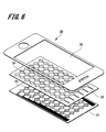
- FIG. 6 shows an example of the configuration of a touch panel including a transparent conductive member having an electrode pattern.
- the touch panel 30 shown in FIG. 6 is a projected capacitive touch panel.
- the touch panel 30 includes a first transparent conductive member 33 patterned on one main surface of the first transparent substrate 31 and a second transparent conductive pattern formed on one main surface of the second transparent substrate 32.
- the members 34 are arranged in this order.
- the upper portions of the second transparent substrate 32 and the second transparent conductive member 34 are covered with the front plate 35.
- Each of the first transparent conductive member 33 and the second transparent conductive member 34 has a desired metal layer pattern according to the conductive region and the non-conductive region shown in the first and second embodiments described above.
- a conductive member can be applied.
- a touch panel can be comprised by laminating
- a transparent substrate (11) As a transparent substrate (11), a polyethylene terephthalate (abbreviation: CHC-PET, manufactured by Kimoto Co.) film on which a double-sided hard coat was formed was prepared. Then, on this CHC-PET film, the first dielectric layer (12) (ZnS-ITO) / metal layer (13) (Ag) / second dielectric layer (14) (by a vapor deposition method according to the following method) ZnS-ITO) were laminated in this order. Then, each formed layer was patterned by the following method, and a transparent conductive member of sample 101 having the same pattern as the wiring shown in FIG. The thickness of each layer is J. A. Woollam Co. Inc. The measurement was made with a VB-250 VASE ellipsometer manufactured by the manufacturer.
- CHC-PET polyethylene terephthalate
- first dielectric layer ZnS-ITO
- a vacuum deposition apparatus a BMC-800T deposition apparatus manufactured by SYNCHRON Co., Ltd. was used. ZnS was loaded on the first resistance heating boat (22) made of molybdenum, and ITO was loaded on the second resistance heating boat (23) made of molybdenum. . Then, after reducing the vacuum tank to 1 ⁇ 10 ⁇ 4 Pa, the first resistance heating boat (22) and the second resistance heating boat (23) are energized and heated, and the current heating conditions of both resistance heating boats are appropriately set.
- the CHC-PET film on which the first dielectric layer (12) is formed is fixed to a vacuum vapor deposition apparatus similar to the above, Ag is loaded into a resistance heating boat (25) made of molybdenum, and the vacuum chamber is set to 1 The pressure was reduced to 10-4 Pa. Then, the resistance heating boat (25) was energized and heated, and was vacuum-deposited on the first dielectric layer under the condition that the formation time was 6 seconds, thereby forming a metal layer (13) having a layer thickness of 7.7 nm. The formation speed at this time was 2.7 nm / second as a result of measurement by the following method.
- the second dielectric layer having a layer thickness of 44 nm is prepared by co-evaporation under the conditions that the volume ratio of ZnS and ITO is 99: 1 and the formation speed is 0.37 nm / second and the formation time is 120 seconds. (14) was formed.
- the volume ratio of ZnS and SiO 2 is 99: 1 in the first resistance heating boat (22, 27).
- the second resistance heating boat (23, 28) was charged with ITO, and the formation rate was 4.3 nm / min under the condition that the volume ratio of ZnS—SiO 2 and ITO was 99: 1. Second, formation time was 10 seconds.
- the first dielectric layer (12) ZnS—SiO 2 —ITO
- metal layer (13) Al
- second dielectric layer (14 ) A transparent conductive member of Sample 105 having a layer structure of (ZnS—SiO 2 —ITO) was prepared.
- Sample 108 was prepared in the same manner as in the preparation of the transparent conductive member of Sample 102 described above, except that ZnS constituting the first dielectric layer (12) and the second dielectric layer (14) was changed to GZO. A transparent conductive member was prepared.
- Sample 109 was prepared in the same manner as in the preparation of the transparent conductive member of Sample 102 described above, except that ZnS constituting the first dielectric layer (12) and the second dielectric layer (14) was changed to ZnO. A transparent conductive member was prepared.
- the first dielectric layer (excluding that the PC200 mixed with 1% of ITO fine particles was formed to 40 nm was formed.
- transparent conductive member of sample 113 The material used to fabricate the first dielectric layer (12) and the second dielectric layer (14) was changed from PC200 to XJA-0291C (titanium oxide particle-dispersed UV curable resin composition, Pernox Corporation).
- a transparent conductive member of Sample 113 was prepared in the same manner as the transparent conductive member of Sample 111 described above, except that after drying, ultraviolet light having an illuminance of 150 mW and a light amount of 100 mJ was irradiated for 5 seconds.
- Sample 115 was prepared in the same manner as in the preparation of the transparent conductive member of Sample 102 described above, except that ITO contained in the first dielectric layer (12) and the second dielectric layer (14) was changed to ATO. A transparent conductive member was prepared.
- Sample 116 was prepared in the same manner as in the preparation of the transparent conductive member of Sample 106 described above except that ITO contained in the first dielectric layer (12) and the second dielectric layer (14) was changed to ATO. A transparent conductive member was prepared.
- Sample 117 is manufactured in the same manner as in the production of the transparent conductive member of Sample 111 described above, except that ITO contained in the first dielectric layer (12) and the second dielectric layer (14) is changed to ATO. A transparent conductive member was prepared.
- the first dielectric layer (12) (ZnS-ITO) / metal layer (13) (Ag) / second dielectric layer (14) on the transparent substrate (11) (CHC-PET film) by the following sputtering method (ZnS-ITO) was laminated in order.
- first dielectric layer (ZnS)) Using a magnetron sputtering apparatus manufactured by Osaka Vacuum Co., Ar: 20 sccm, O 2 : 0 sccm, sputtering pressure 0.1 Pa, room temperature, target side power 150 W, formation rate 0.3. Under the condition of nm / second, a ZnS target and an ITO target were juxtaposed in a volume ratio of 85:15 and RF sputtering was performed to form a first dielectric layer (12) having a layer thickness of 28 nm. The target-substrate distance was 90 mm.
- the first dielectric layer (12) and the second dielectric layer (14) are made of only ZnS and do not contain ITO, except that the first dielectric layer (12) ), A metal layer (13), and a second dielectric layer (14). Then, the formed first dielectric layer (12), metal layer (13), and second dielectric layer (14) were patterned by the following method.
- the first dielectric layer (12), the metal layer (13), and the second dielectric layer (14) were subjected to ultrasonic cleaning treatment.
- An ultrasonic cleaning treatment was performed at 25 ° C. for 4 minutes using a detergent “Clean 30-30 (10%)” manufactured by Kao Corporation as a cleaning solution.
- a detergent “Clean 30-30 (10%)” manufactured by Kao Corporation as a cleaning solution.
- ultrasonic washing with pure water at 25 ° C. was performed twice for 4 minutes.
- OFPR-800LB manufactured by Tokyo Ohka Kogyo Co., Ltd. is applied as a resist on the cleaned first dielectric layer (12), metal layer (13), and second dielectric layer (14) by spin coating. Then, application and drying were performed at 2000 rpm for 30 seconds to form a resist layer having a thickness of 1 ⁇ m.
- ultraviolet rays were irradiated through a mask under conditions of 60 mJ, and developed using a developer for positive photoresist “Tokuso SD-1” (tetramethylammonium hydroxide) manufactured by Tokuyama Corporation as a developer. .
- Yamaso SD-1 tetramethylammonium hydroxide
- ITO series manufactured by Kanto Chemical Co., Ltd. is used as an etchant, and the non-conductive region (17) where the transparent substrate is exposed, the first dielectric layer (12), the metal layer (13), and the second An electrode pattern composed of a current-carrying region (16) in which the dielectric layer (14) remained was formed.
- the width of the line-shaped non-conducting region (17) was 16 ⁇ m.
- the remaining resist layer was peeled off using acetone to form an electrode pattern having wiring.
- the transparent conductive member of the sample 121 was formed in the same manner as the sample 101 except that the first dielectric layer (12) and the second dielectric layer (14) were formed only of ZnS and did not contain ITO. Produced.
- permeability was measured in accordance with the following method.
- the transparent conductive member and a non-alkali glass substrate (EAGLE XG (thickness 7 mm ⁇ length 30 mm ⁇ width 30 mm) manufactured by Corning) were bonded together, and the average in the wavelength range of 400 to 1200 nm from the alkali-free glass substrate side.
- the transmittance (%) was measured.
- measurement light for example, light having a wavelength of 450 nm to 1200 nm
- the light transmittance was measured at U4100.
- the absorptance (%) of the laser light wavelength 1064 nm of each sample was measured.
- the transparent conductive members of Samples 101 to 119 having infrared absorbing compounds in the first dielectric layer and the second dielectric layer have absorption in the 1064 nm laser. Yes. For this reason, it can be seen that desired etching is possible with the laser, and the transmittance, resistance value, and haze are good.
- the transparent conductive members of the sample 120 and the sample 121 that do not have the infrared absorbing compound in the first dielectric layer and the second dielectric layer do not have absorption in the 1064 nm laser.
- the transparent conductive member of the sample 121 was not satisfactorily laser-etched and could not be measured for each evaluation after the etching. Further, even in the sample 120 subjected to wet etching, the etching was not performed well, and each evaluation after the etching could not be measured.
Abstract
This transparent conductive member is configured so as to be provided with a first dielectric layer, a second dielectric layer, and a metal layer that is formed between the first dielectric layer and the second dielectric layer. This transparent conductive member is also configured such that the first dielectric layer and the second dielectric layer contain an infrared absorbing compound.
Description
本発明は、金属層と誘電体層とを有する透明導電部材、及び、この透明導電部材の製造方法に関する。
The present invention relates to a transparent conductive member having a metal layer and a dielectric layer, and a method for manufacturing the transparent conductive member.
近年、タッチパネル材料、液晶ディスプレイやプラズマディスプレイ、無機及び有機EL(エレクトロルミネッセンス)ディスプレイ等の表示装置、太陽電池等の各種装置に、低抵抗な透明導電膜が求められている。このような透明導電膜を構成する材料として、例えば、Au、Ag、Pt、Cu、Rh、Pd、Al、Cr等の金属や、In2O3、CdO、CdIn2O4、Cd2SnO4、TiO2、SnO2、ZnO、ITO(酸化インジウムスズ)等の酸化物半導体が知られている。
In recent years, low resistance transparent conductive films are required for various devices such as touch panel materials, liquid crystal displays, plasma displays, inorganic and organic EL (electroluminescence) displays, and solar cells. As a material constituting such a transparent conductive film, for example, metals such as Au, Ag, Pt, Cu, Rh, Pd, Al, Cr, In 2 O 3 , CdO, CdIn 2 O 4 , Cd 2 SnO 4 are used. , TiO 2 , SnO 2 , ZnO, ITO (indium tin oxide) and other oxide semiconductors are known.
また、タッチパネル型の表示装置等では、表示素子の画像表示面上に、透明導電膜等からなる配線が配置される。このため、透明導電膜には、光の透過性が高いことが求められている。従来、このような各種表示装置には、光透過性の高いITOからなる透明導電膜が多用されている。
Further, in a touch panel type display device or the like, a wiring made of a transparent conductive film or the like is disposed on the image display surface of the display element. For this reason, the transparent conductive film is required to have high light transmittance. Conventionally, a transparent conductive film made of ITO having a high light transmittance is often used in such various display devices.
近年、静電容量方式のタッチパネル表示装置が開発され、透明導電膜の表面電気抵抗をさらに低く、具体的には、50Ω/sq.以下の抵抗値が強く求められている。しかし、従来、広く用いられているITO膜では、抵抗値としては150Ω/sq.程度にとどまっており、上記の要望に対しては不十分な特性であった。
In recent years, a capacitive touch panel display device has been developed, and the surface electrical resistance of the transparent conductive film is further reduced, specifically, 50Ω / sq. The following resistance values are strongly demanded. However, a conventionally used ITO film has a resistance value of 150 Ω / sq. However, the characteristics were insufficient for the above demand.
このような背景から、近年、ITOに代わる次世代の透明導電膜の開発が盛んに行なわれている。例えば、導電層となる銀の両面に高屈折率の層を形成することで、透明性と導電性を両立することを目的とした透明導電部材が提案されている(例えば、特許文献1参照)。
Against this background, in recent years, development of a next-generation transparent conductive film that replaces ITO has been actively conducted. For example, a transparent conductive member has been proposed that aims to achieve both transparency and conductivity by forming layers having a high refractive index on both surfaces of silver serving as a conductive layer (see, for example, Patent Document 1). .
しかしながら、静電容量式タッチパネルの場合、パターンエッチングを行う必要があるため、上述の銀の両面に高屈折率の層を形成する構成の透明導電部材では、2層の高屈折率層と、銀層との3層以上を同時にエッチングする必要がある。
However, in the case of a capacitive touch panel, it is necessary to perform pattern etching. Therefore, in the transparent conductive member configured to form a high refractive index layer on both sides of the above-described silver, two high refractive index layers and silver It is necessary to simultaneously etch three or more layers with the layer.
フォトリソグラフィーによるエッチングを行う場合、材料の異なる3層を一度にエッチングすることは、適切なエッチャントを選択することが難しく、エッチングプロセスとの整合も難しい。また、レーザエッチングによるパターンエッチングの場合には、エッチングする全ての層にそのレーザ波長の吸収が必要になるため、適用が困難とされている。
このように、導電層と高屈折率層等の異なる種類の積層体を有する透明導電部材では、エッチング工程における生産性の低下が問題となっている。 When performing etching by photolithography, it is difficult to select an appropriate etchant and to match the etching process to etch three layers of different materials at once. Further, in the case of pattern etching by laser etching, it is difficult to apply because all the layers to be etched need to absorb the laser wavelength.
Thus, in the transparent conductive member having different types of laminates such as a conductive layer and a high refractive index layer, a decrease in productivity in the etching process is a problem.
上述した問題の解決のため、本発明においては、高い生産性を有する透明導電部材、及び、透明導電部材の製造方法を提供するものである。
In order to solve the above-described problems, the present invention provides a transparent conductive member having high productivity and a method for producing the transparent conductive member.
本発明の透明導電部材は、第1誘電体層と、第2誘電体層と、第1誘電体層と第2誘電体層との間に形成された金属層とを備える。そして、第1誘電体層と第2誘電体層とに、赤外線吸収性化合物が含まれている。
The transparent conductive member of the present invention includes a first dielectric layer, a second dielectric layer, and a metal layer formed between the first dielectric layer and the second dielectric layer. The first dielectric layer and the second dielectric layer contain an infrared absorbing compound.
また、本発明の透明導電部材の製造方法は、赤外線吸収性化合物を含む第1誘電体層を形成する工程と、第1誘電体層上に金属層を形成する工程と、金属層上に、赤外線吸収性化合物を含む第2誘電体層を形成する工程とを有する。
The transparent conductive member manufacturing method of the present invention includes a step of forming a first dielectric layer containing an infrared absorbing compound, a step of forming a metal layer on the first dielectric layer, and a metal layer. Forming a second dielectric layer containing an infrared absorbing compound.
上述の透明導電部材、及び、透明導電部材の製造方法では、第1誘電体層と、第2誘電体層とに、赤外線吸収性化合物が含まれている。このため、レーザ光を照射することにより、金属層とともに、赤外線吸収性化合物が含まれている第1誘電体層及び第2誘電体層を、エッチングすることができる。このため、この構成の透明導電部材を用いることにより、導通領域と非導通領域のパターン形成を容易に行なうことができる。つまり、上述の構成の透明導電部材を形成することにより、高い生産性を有する透明導電部材を提供することができる。
In the above-described transparent conductive member and transparent conductive member manufacturing method, the first dielectric layer and the second dielectric layer contain an infrared absorbing compound. For this reason, by irradiating the laser beam, the first dielectric layer and the second dielectric layer containing the infrared absorbing compound can be etched together with the metal layer. For this reason, by using the transparent conductive member having this configuration, it is possible to easily perform pattern formation of the conductive region and the non-conductive region. That is, a transparent conductive member having high productivity can be provided by forming the transparent conductive member having the above-described configuration.
本発明によれば、高い生産性を有する透明導電部材、及び、透明導電部材の製造方法を提供することができる。
According to the present invention, it is possible to provide a transparent conductive member having high productivity and a method for producing the transparent conductive member.
以下、本発明を実施するための形態の例を説明するが、本発明は以下の例に限定されるものではない。
なお、説明は以下の順序で行う。
1.透明導電部材の実施形態(第1実施形態)
2.透明導電部材の実施形態(第2実施形態)
3.透明導電部材の製造方法(第3実施形態)
4.電子デバイス Hereinafter, although the example of the form for implementing this invention is demonstrated, this invention is not limited to the following examples.
The description will be given in the following order.
1. Embodiment of transparent conductive member (first embodiment)
2. Embodiment of transparent conductive member (second embodiment)
3. Method for manufacturing transparent conductive member (third embodiment)
4). Electronic devices
〈1.透明導電部材の実施形態(第1実施形態)〉
以下、本発明の透明導電部材の具体的な実施の形態について説明する。図1及び図2に、第1実施形態の透明導電部材の概略構成(断面図)を示す。 <1. Embodiment of Transparent Conductive Member (First Embodiment)>
Hereinafter, specific embodiments of the transparent conductive member of the present invention will be described. 1 and 2 show a schematic configuration (cross-sectional view) of the transparent conductive member of the first embodiment.
[透明導電部材の基本的な構成]
図1に示す構成の透明導電部材10は、第1誘電体層12と、金属層13と、第2誘電体層14とをこの順で積層した構成を有している。そして、透明導電部材10が透明基板11上に設けられている。 [Basic configuration of transparent conductive member]
The transparentconductive member 10 having the configuration shown in FIG. 1 has a configuration in which a first dielectric layer 12, a metal layer 13, and a second dielectric layer 14 are laminated in this order. A transparent conductive member 10 is provided on the transparent substrate 11.
図1に示す構成の透明導電部材10は、第1誘電体層12と、金属層13と、第2誘電体層14とをこの順で積層した構成を有している。そして、透明導電部材10が透明基板11上に設けられている。 [Basic configuration of transparent conductive member]
The transparent
また、図2に示す透明導電部材10は、透明基板11上に設けられた第1誘電体層12、金属層13、及び、第2誘電体層14による積層体の一部が、パターンエッチングされた状態を示している。
このパターンエッチングにより、第1誘電体層12、金属層13、及び、第2誘電体層14が除去されて、第2誘電体層14の表面側から透明基板11の表面が露出する、開口部15が設けられている。このように開口部15を設けることにより、金属層13が連続形成された導通領域16と、金属層13が形成されてない非導通領域17とを有し、所望の導電層のパターンを有する透明導電部材10を形成することができる。
なお、図1に示す透明導電部材10では、透明基板11上の全面に金属層13が形成されている構成であるため、この金属層13が形成されている全領域が導通領域16である。
以下、透明導電部材10の各構成の詳細について説明する。 Further, in the transparentconductive member 10 shown in FIG. 2, a part of the laminated body including the first dielectric layer 12, the metal layer 13, and the second dielectric layer 14 provided on the transparent substrate 11 is subjected to pattern etching. Shows the state.
By this pattern etching, the firstdielectric layer 12, the metal layer 13, and the second dielectric layer 14 are removed, and the surface of the transparent substrate 11 is exposed from the surface side of the second dielectric layer 14. 15 is provided. By providing the opening 15 in this manner, a transparent region having a conductive region 16 in which the metal layer 13 is continuously formed and a non-conductive region 17 in which the metal layer 13 is not formed and having a desired conductive layer pattern is provided. The conductive member 10 can be formed.
In the transparentconductive member 10 shown in FIG. 1, the metal layer 13 is formed on the entire surface of the transparent substrate 11. Therefore, the entire region where the metal layer 13 is formed is the conduction region 16.
Hereinafter, the detail of each structure of the transparentconductive member 10 is demonstrated.
このパターンエッチングにより、第1誘電体層12、金属層13、及び、第2誘電体層14が除去されて、第2誘電体層14の表面側から透明基板11の表面が露出する、開口部15が設けられている。このように開口部15を設けることにより、金属層13が連続形成された導通領域16と、金属層13が形成されてない非導通領域17とを有し、所望の導電層のパターンを有する透明導電部材10を形成することができる。
なお、図1に示す透明導電部材10では、透明基板11上の全面に金属層13が形成されている構成であるため、この金属層13が形成されている全領域が導通領域16である。
以下、透明導電部材10の各構成の詳細について説明する。 Further, in the transparent
By this pattern etching, the first
In the transparent
Hereinafter, the detail of each structure of the transparent
[金属層]
金属層13は、透明導電部材10において電気を導通させるための金属を含む層である。金属層13は、図1に示すように透明基板11の全面に形成されていてもよく、また、図2に示すように所望の形状にパターニングされていてもよい。 [Metal layer]
Themetal layer 13 is a layer containing a metal for conducting electricity in the transparent conductive member 10. The metal layer 13 may be formed on the entire surface of the transparent substrate 11 as shown in FIG. 1, or may be patterned into a desired shape as shown in FIG.
金属層13は、透明導電部材10において電気を導通させるための金属を含む層である。金属層13は、図1に示すように透明基板11の全面に形成されていてもよく、また、図2に示すように所望の形状にパターニングされていてもよい。 [Metal layer]
The
金属層13に含まれる金属は、導電性の高い金属であれば特に制限されず、例えば銀、銅、金、白金族、チタン、及び、クロム等を挙げることができる。金属層13には、これらの金属が1種のみ含まれてもよく、2種以上含まれてもよい。
The metal contained in the metal layer 13 is not particularly limited as long as it is a highly conductive metal, and examples thereof include silver, copper, gold, platinum group, titanium, and chromium. The metal layer 13 may contain only one kind of these metals or two or more kinds.
導電性が高いという観点から、金属層13に含まれる金属としては銀、又は、銀が90原子%以上含まれる合金が好ましい。銀と組み合わされる金属としては、亜鉛、金、銅、パラジウム、アルミニウム、マンガン、ビスマス、ネオジム、及び、モリブデン等が挙げられる。例えば、銀と亜鉛とが組み合わされると、金属層13の耐硫化性が高まるため好ましい。また、銀と金とが組み合わされると、耐塩(NaCl)性が高まるため好ましい。さらに、銀と銅とが組み合わされると、耐酸化性が高まるため好ましい。
From the viewpoint of high conductivity, the metal contained in the metal layer 13 is preferably silver or an alloy containing 90 atomic% or more of silver. Examples of the metal combined with silver include zinc, gold, copper, palladium, aluminum, manganese, bismuth, neodymium, and molybdenum. For example, a combination of silver and zinc is preferable because the sulfidation resistance of the metal layer 13 is increased. A combination of silver and gold is preferable because salt resistance (NaCl) resistance is increased. Furthermore, when silver and copper are combined, oxidation resistance is increased, which is preferable.
金属層13のプラズモン吸収率は、波長400~800nmにわたって(全範囲で)10%以下であることが好ましく、7%以下であることがより好ましく、5%以下であることがさらに好ましい。波長400~800nmの一部にプラズモン吸収率が大きい領域があると、透明導電部材10の導通領域16の透過光が着色しやすくなる。
The plasmon absorption rate of the metal layer 13 is preferably 10% or less, more preferably 7% or less, and further preferably 5% or less over the wavelength range of 400 to 800 nm (over the entire range). If there is a region having a large plasmon absorption rate in a part of the wavelength of 400 to 800 nm, the transmitted light of the conductive region 16 of the transparent conductive member 10 is likely to be colored.
金属層13の波長400~800nmにおけるプラズモン吸収率は、以下(i)~(iii)の手順で測定される。
The plasmon absorption rate at a wavelength of 400 to 800 nm of the metal layer 13 is measured by the following procedures (i) to (iii).
(i)ガラス基板上に、白金パラジウムをシンクロン社製のBMC-800T蒸着装置にて0.1nmの厚さで形成する。白金パラジウムの平均厚さは、蒸着装置のメーカー公称値の形成速度等から算出する。その後、白金パラジウムが付着した基板上に、真空蒸着法にて金属層を20nmの厚さで形成する。
(I) On a glass substrate, platinum palladium is formed to a thickness of 0.1 nm by a BMC-800T vapor deposition apparatus manufactured by SYNCHRON. The average thickness of platinum palladium is calculated from the formation rate of the manufacturer's nominal value of the vapor deposition apparatus. Thereafter, a metal layer having a thickness of 20 nm is formed on the substrate to which platinum palladium is adhered by vacuum deposition.
(ii)得られた金属層の表面の法線に対して、5°傾けた角度から測定光を入射させ、金属層の透過率及び反射率を測定する。そして各波長における透過率及び反射率から、[吸収率=100-(透過率+反射率)]を算出し、これをリファレンスデータとする。透過率及び反射率は、分光光度計で測定する。
(Ii) Measuring light is incident from an angle inclined by 5 ° with respect to the normal of the surface of the obtained metal layer, and the transmittance and reflectance of the metal layer are measured. Then, [absorbance = 100− (transmittance + reflectance)] is calculated from the transmittance and reflectance at each wavelength, and this is used as reference data. The transmittance and reflectance are measured with a spectrophotometer.
(iii)続いて、測定対象の金属層を同様のガラス基板上に形成する。そして、当該金属層について、同様に透過率及び反射率を測定する。得られた吸収率から上記リファレンスデータを差し引き、算出された値を、金属層のプラズモン吸収率とする。
(Iii) Subsequently, a metal layer to be measured is formed on the same glass substrate. And the transmittance | permeability and a reflectance are similarly measured about the said metal layer. The reference data is subtracted from the obtained absorption rate, and the calculated value is defined as the plasmon absorption rate of the metal layer.
金属層13の厚さは10nm以下であることが好ましく、より好ましくは3~9nmの範囲内であり、さらに好ましくは5~8nmの範囲内である。透明導電部材10では、金属層13の厚さを10nm以下とすることにより、金属層13に金属本来の反射が生じ難くなる。さらに、金属層13の厚さが10nm以下であると、第1誘電体層12及び第2誘電体層14による、透明導電部材10の光学アドミッタンスが調整しやすく、導通領域16表面での光の反射の抑制が容易となる。金属層13の厚さは、エリプソメーターを用いた測定で求めることができる。
The thickness of the metal layer 13 is preferably 10 nm or less, more preferably in the range of 3 to 9 nm, and still more preferably in the range of 5 to 8 nm. In the transparent conductive member 10, when the thickness of the metal layer 13 is 10 nm or less, the metal layer 13 is less likely to reflect the original metal. Furthermore, when the thickness of the metal layer 13 is 10 nm or less, the optical admittance of the transparent conductive member 10 by the first dielectric layer 12 and the second dielectric layer 14 can be easily adjusted, and light on the surface of the conductive region 16 can be adjusted. It is easy to suppress reflection. The thickness of the metal layer 13 can be obtained by measurement using an ellipsometer.
金属層13は、いずれの方法で形成された層でもよいが、真空蒸着法で形成された層であることが好ましい。真空蒸着法であれば、高温環境に透明基板11をさらすことがなく、平面性の高い金属層13を、極めて早く形成することができる。
The metal layer 13 may be a layer formed by any method, but is preferably a layer formed by a vacuum deposition method. If it is a vacuum evaporation method, the transparent substrate 11 will not be exposed to a high temperature environment, but the metal layer 13 with high planarity can be formed very quickly.
一方、金属層13が後述する下地層上に形成された層である場合、金属層13の形成時に下地層が成長核となるため、金属層13が平滑な膜になりやすい。その結果、金属層13が薄くとも、プラズモン吸収が生じ難くなる。
On the other hand, when the metal layer 13 is a layer formed on an underlayer described later, the underlayer becomes a growth nucleus when the metal layer 13 is formed, so that the metal layer 13 tends to be a smooth film. As a result, even if the metal layer 13 is thin, plasmon absorption hardly occurs.
また、金属層13が所望の形状にパターニングされた層である場合、パターニング方法は特に制限されない。金属層13は、例えば、所望のパターンを有するマスクを配置して形成された層であってもよく、公知のエッチング法によってパターニングされた層であってもよい。
Further, when the metal layer 13 is a layer patterned into a desired shape, the patterning method is not particularly limited. For example, the metal layer 13 may be a layer formed by arranging a mask having a desired pattern, or may be a layer patterned by a known etching method.
[第1誘電体層、第2誘電体層]
第1誘電体層12、及び、第2誘電体層14は、透明導電部材10の導通領域16、つまり金属層13が形成されている領域の光透過性(光学アドミッタンス)を調整する層であり、少なくとも透明導電部材10の導通領域16に形成される。第1誘電体層12、及び、第2誘電体層14は、透明導電部材10の非導通領域17にも形成されていてもよいが、導通領域16及び非導通領域17からなるパターンを視認され難くする観点から、導通領域16のみに形成され、図2に示すように非導通領域17からは除去されていることが好ましい。 [First dielectric layer, second dielectric layer]
Thefirst dielectric layer 12 and the second dielectric layer 14 are layers that adjust the light transmittance (optical admittance) of the conductive region 16 of the transparent conductive member 10, that is, the region where the metal layer 13 is formed. At least the conductive region 16 of the transparent conductive member 10 is formed. Although the first dielectric layer 12 and the second dielectric layer 14 may be formed also in the non-conductive region 17 of the transparent conductive member 10, a pattern composed of the conductive region 16 and the non-conductive region 17 is visually recognized. From the viewpoint of making it difficult, it is preferably formed only in the conductive region 16 and removed from the non-conductive region 17 as shown in FIG.
第1誘電体層12、及び、第2誘電体層14は、透明導電部材10の導通領域16、つまり金属層13が形成されている領域の光透過性(光学アドミッタンス)を調整する層であり、少なくとも透明導電部材10の導通領域16に形成される。第1誘電体層12、及び、第2誘電体層14は、透明導電部材10の非導通領域17にも形成されていてもよいが、導通領域16及び非導通領域17からなるパターンを視認され難くする観点から、導通領域16のみに形成され、図2に示すように非導通領域17からは除去されていることが好ましい。 [First dielectric layer, second dielectric layer]
The
第1誘電体層12、及び、第2誘電体層14は、赤外線吸収性化合物を含んでいる。
第1誘電体層12、及び、第2誘電体層14に含まれる赤外線吸収性化合物としては、例えば、ZnO、AZO、IZO、GZO、酸化錫、ATO、ITO、ホウ素化ランタン、及び、ニッケル錯体系化合物等を用いることができる。具体的な商品名としては、酸化亜鉛系として、セルナックスシリーズ(日産化学工業社製)、パゼットシリーズ(ハクスイテック社製)、酸化錫系として、ATO分散液、ITO分散液(三菱マテリアル製)、KHシリーズ(住友金属鉱山社製)等が挙げられる。
また、第1誘電体層12、及び、第2誘電体層14に含まれる赤外線吸収性化合物としては、有機系として、イモニウム系、フタロシアニン系、アミニウム系化合物を利用することができる。具体的な商品名として、NIR-IM1、NIR-AM1(ナガセケミテックス社製)、Lumogenシリーズ(BASF社製)等が挙げられる。 Thefirst dielectric layer 12 and the second dielectric layer 14 contain an infrared absorbing compound.
Examples of the infrared absorbing compound included in thefirst dielectric layer 12 and the second dielectric layer 14 include ZnO, AZO, IZO, GZO, tin oxide, ATO, ITO, lanthanum boride, and nickel complex. Systemic compounds and the like can be used. Specific product names include: zinc oxide series, Cellax series (manufactured by Nissan Chemical Industries, Ltd.), passet series (manufactured by Hakusui Tech Co., Ltd.), tin oxide series, ATO dispersion, ITO dispersion (manufactured by Mitsubishi Materials) And KH series (manufactured by Sumitomo Metal Mining Co., Ltd.).
In addition, as the infrared absorbing compound contained in thefirst dielectric layer 12 and the second dielectric layer 14, an organic compound such as an imonium compound, a phthalocyanine compound, or an aminium compound can be used. Specific product names include NIR-IM1, NIR-AM1 (manufactured by Nagase Chemitex), Lumogen series (manufactured by BASF), and the like.
第1誘電体層12、及び、第2誘電体層14に含まれる赤外線吸収性化合物としては、例えば、ZnO、AZO、IZO、GZO、酸化錫、ATO、ITO、ホウ素化ランタン、及び、ニッケル錯体系化合物等を用いることができる。具体的な商品名としては、酸化亜鉛系として、セルナックスシリーズ(日産化学工業社製)、パゼットシリーズ(ハクスイテック社製)、酸化錫系として、ATO分散液、ITO分散液(三菱マテリアル製)、KHシリーズ(住友金属鉱山社製)等が挙げられる。
また、第1誘電体層12、及び、第2誘電体層14に含まれる赤外線吸収性化合物としては、有機系として、イモニウム系、フタロシアニン系、アミニウム系化合物を利用することができる。具体的な商品名として、NIR-IM1、NIR-AM1(ナガセケミテックス社製)、Lumogenシリーズ(BASF社製)等が挙げられる。 The
Examples of the infrared absorbing compound included in the
In addition, as the infrared absorbing compound contained in the
また、第1誘電体層12、及び、第2誘電体層14には、後述する透明基板11の屈折率より高い屈折率を有する誘電性材料、又は、酸化物半導体材料が含まれる。当該誘電性材料、又は、酸化物半導体材料の波長570nmの光の屈折率は、透明基板11の波長570nmの光の屈折率より0.1~1.1大きいことが好ましく、0.4~1.0大きいことがより好ましい。なお、屈折率とは、25℃の環境下で測定した屈折率の値を用いる。また、屈折率は、市販のエリプソメーターを用いて測定して求めることができる。
Further, the first dielectric layer 12 and the second dielectric layer 14 include a dielectric material having a refractive index higher than that of the transparent substrate 11 described later, or an oxide semiconductor material. The refractive index of light having a wavelength of 570 nm of the dielectric material or the oxide semiconductor material is preferably 0.1 to 1.1 larger than the refractive index of light having a wavelength of 570 nm of the transparent substrate 11, and 0.4 to 1 It is more preferable that the value be larger by 0.0. In addition, the value of the refractive index measured in a 25 degreeC environment is used for a refractive index. The refractive index can be determined by measuring using a commercially available ellipsometer.
第1誘電体層12、及び、第2誘電体層14に含まれる誘電性材料、又は、酸化物半導体材料の波長570nmの光の具体的な屈折率は1.5より大きいことが好ましく、1.7~2.5であることがより好ましく、さらに好ましくは1.8~2.5である。誘電性材料、又、は酸化物半導体材料の屈折率が1.5より大きいと、第1誘電体層12、及び、第2誘電体層14によって、透明導電部材10の導通領域16の光学アドミッタンスが十分に調整される。なお、第1誘電体層12、及び、第2誘電体層14の屈折率は、含まれる材料の屈折率や、材料の密度で調整される。
The specific refractive index of light having a wavelength of 570 nm of the dielectric material or oxide semiconductor material included in the first dielectric layer 12 and the second dielectric layer 14 is preferably greater than 1.5. It is more preferably from 7 to 2.5, still more preferably from 1.8 to 2.5. When the refractive index of the dielectric material or the oxide semiconductor material is larger than 1.5, the first dielectric layer 12 and the second dielectric layer 14 cause the optical admittance of the conductive region 16 of the transparent conductive member 10. Is fully adjusted. In addition, the refractive index of the 1st dielectric material layer 12 and the 2nd dielectric material layer 14 is adjusted with the refractive index of the material contained, and the density of material.
第1誘電体層12、及び、第2誘電体層14には、硫化亜鉛、金属酸化物、無機酸化物、硫化亜鉛と金属酸化物の混合物、硫化亜鉛と無機酸化物の混合物、酸化チタン(TiO2)、ガリウムドープト酸化錫(GZO)、酸化亜鉛(ZnO)、アルミニウムドープト酸化亜鉛、アンチモンドープト酸化錫(ATO)、アンチモンドープト酸化亜鉛(AZO)、インジウムドープト酸化錫(ITO)、及び、インジウムドープト酸化亜鉛(IZO)等を用いることができる。
The first dielectric layer 12 and the second dielectric layer 14 include zinc sulfide, metal oxide, inorganic oxide, a mixture of zinc sulfide and metal oxide, a mixture of zinc sulfide and inorganic oxide, titanium oxide ( TiO 2 ), gallium-doped tin oxide (GZO), zinc oxide (ZnO), aluminum-doped zinc oxide, antimony-doped tin oxide (ATO), antimony-doped zinc oxide (AZO), indium-doped tin oxide (ITO) ), Indium-doped zinc oxide (IZO), or the like can be used.
硫化亜鉛と共に用いることができる金属酸化物、無機酸化物としては、例えば、TiO2、ITO(酸化インジウムスズ)、ZnO、Nb2O5、ZrO2、CeO2、Ta2O5、Ti3O5、Ti4O7、Ti2O3、TiO、SnO2、La2Ti2O7、(酸化インジウム・酸化亜鉛)、AZO(AlドープZnO)、GZO(GaドープZnO)、ATO(SbドープSnO)、ICO(インジウムセリウムオキサイド)、Bi2O3、a-GIO、Ga2O3、GeO2、SiO2、Al2O3、HfO2、SiO、MgO、Y2O3、WO3、及び、a-GIO(ガリウム、インジウム、及び酸素からなる非晶質酸化物)等が挙げられる。上記無機酸化物の中でも、特に、二酸化ケイ素(SiO2)が好ましい。
Examples of the metal oxide and inorganic oxide that can be used together with zinc sulfide include TiO 2 , ITO (indium tin oxide), ZnO, Nb 2 O 5 , ZrO 2 , CeO 2 , Ta 2 O 5 , and Ti 3 O. 5 , Ti 4 O 7 , Ti 2 O 3 , TiO, SnO 2 , La 2 Ti 2 O 7 , (indium / zinc oxide), AZO (Al-doped ZnO), GZO (Ga-doped ZnO), ATO (Sb-doped) SnO), ICO (Indium Cerium Oxide), Bi 2 O 3 , a-GIO, Ga 2 O 3 , GeO 2 , SiO 2 , Al 2 O 3 , HfO 2 , SiO, MgO, Y 2 O 3 , WO 3 , And a-GIO (amorphous oxide composed of gallium, indium, and oxygen). Among the inorganic oxides, silicon dioxide (SiO 2 ) is particularly preferable.
また、第1誘電体層12、及び、第2誘電体層14には、金属フッ化物を用いることができる。金属フッ化物としては、LaF3、BaF2、Na5Al3F14、Na3AlF6、AlF3、MgF2、CaF2、CeF3、NdF3、及び、YF3等を挙げることができる。
Further, a metal fluoride can be used for the first dielectric layer 12 and the second dielectric layer 14. Examples of the metal fluoride include LaF 3 , BaF 2 , Na 5 Al 3 F 14 , Na 3 AlF 6 , AlF 3 , MgF 2 , CaF 2 , CeF 3 , NdF 3 , and YF 3 .
また、第1誘電体層12、及び、第2誘電体層14には、金属窒化物を用いることができる。金属窒化物としては、窒化ホウ素、窒化アルミニウム、窒化クロム、窒化ケイ素、窒化タングステン、窒化マグネシウム、窒化モリブデン、窒化リチウム、及び、窒化チタン等を挙げることができる。
Further, metal nitride can be used for the first dielectric layer 12 and the second dielectric layer 14. Examples of the metal nitride include boron nitride, aluminum nitride, chromium nitride, silicon nitride, tungsten nitride, magnesium nitride, molybdenum nitride, lithium nitride, and titanium nitride.
第1誘電体層12、及び、第2誘電体層14は、誘電性材料として、少なくとも硫化亜鉛(ZnS)を含有することが好ましい。第1誘電体層12、及び、第2誘電体層14が硫化亜鉛を含むことにより、透明基板11側等からの水分が第1誘電体層12、及び、第2誘電体層14を透過し難くなり、金属層13の腐食が抑制される。
The first dielectric layer 12 and the second dielectric layer 14 preferably contain at least zinc sulfide (ZnS) as a dielectric material. Since the first dielectric layer 12 and the second dielectric layer 14 contain zinc sulfide, moisture from the transparent substrate 11 side or the like passes through the first dielectric layer 12 and the second dielectric layer 14. It becomes difficult and corrosion of the metal layer 13 is suppressed.
また、透明導電部材10では、第1誘電体層12、及び、第2誘電体層14として、硫化亜鉛と共に、金属酸化物、無機酸化物、金属フッ化物及び金属窒化物から選ばれる少なくとも1種の化合物を共蒸着することにより、第1誘電体層12、及び、第2誘電体層14が非晶質になりやすく、透明導電部材10のフレキシブル性が高まりやすい。
In the transparent conductive member 10, the first dielectric layer 12 and the second dielectric layer 14 are at least one selected from metal oxides, inorganic oxides, metal fluorides, and metal nitrides together with zinc sulfide. By co-evaporating this compound, the first dielectric layer 12 and the second dielectric layer 14 are likely to be amorphous, and the flexibility of the transparent conductive member 10 is likely to be enhanced.
第1誘電体層12、及び、第2誘電体層14において、硫化亜鉛の平均含有量は、この層を構成する材料の総モル数に対して、0.5~99質量%の範囲内であることが好ましく、50~95質量%の範囲内であることがより好ましく、さらに好ましくは60~85質量%の範囲内である。硫化亜鉛の比率が高いと共蒸着速度が速くなり、第1誘電体層12、及び、第2誘電体層14の形成速度が速くなる。また、硫化亜鉛の比率が高いと屈折率が高くなり、金属層13での光の吸収を低減することができる。一方、硫化亜鉛以外の成分が多く含まれると、第1誘電体層12、及び、第2誘電体層14の非晶質性が高まり、第1誘電体層12、及び、第2誘電体層14の割れ(クラック)の発生が抑制される。
In the first dielectric layer 12 and the second dielectric layer 14, the average content of zinc sulfide is within the range of 0.5 to 99 mass% with respect to the total number of moles of the material constituting the layer. It is preferably within a range of 50 to 95% by mass, and more preferably within a range of 60 to 85% by mass. When the ratio of zinc sulfide is high, the co-evaporation rate is increased, and the formation rate of the first dielectric layer 12 and the second dielectric layer 14 is increased. Moreover, when the ratio of zinc sulfide is high, the refractive index is increased, and light absorption in the metal layer 13 can be reduced. On the other hand, when many components other than zinc sulfide are contained, the amorphousness of the first dielectric layer 12 and the second dielectric layer 14 is increased, and the first dielectric layer 12 and the second dielectric layer are increased. The occurrence of 14 cracks is suppressed.
第1誘電体層12の厚さTAは、10~150nmの範囲内であることが好ましく、より好ましくは10~80nmの範囲内である。同様に、第2誘電体層14厚さTBは、10~150nmの範囲内であることが好ましく、より好ましくは10~80nmの範囲内である。
第1誘電体層12、及び、第2誘電体層14の厚さが10nm以上であると、第1誘電体層12、及び、第2誘電体層14によって、透明導電部材10の導通領域16の光学アドミッタンスが十分に調整される。一方、第1誘電体層12、及び、第2誘電体層14の厚さが150nm以下であれば、第1誘電体層12、及び、第2誘電体層14が形成されている領域の光透過性が低下し難い。第1誘電体層12、及び、第2誘電体層14の厚さは、エリプソメーターで測定される。 The thickness T A of thefirst dielectric layer 12, preferably in the range of 10 ~ 150 nm, more preferably in the range of 10 ~ 80 nm. Similarly, the second dielectric layer 14 thickness T B is preferably in the range of 10 ~ 150 nm, more preferably in the range of 10 ~ 80 nm.
When the thicknesses of thefirst dielectric layer 12 and the second dielectric layer 14 are 10 nm or more, the conductive regions 16 of the transparent conductive member 10 are formed by the first dielectric layer 12 and the second dielectric layer 14. The optical admittance is sufficiently adjusted. On the other hand, if the thickness of the first dielectric layer 12 and the second dielectric layer 14 is 150 nm or less, the light in the region where the first dielectric layer 12 and the second dielectric layer 14 are formed. The permeability is difficult to decrease. The thicknesses of the first dielectric layer 12 and the second dielectric layer 14 are measured with an ellipsometer.
第1誘電体層12、及び、第2誘電体層14の厚さが10nm以上であると、第1誘電体層12、及び、第2誘電体層14によって、透明導電部材10の導通領域16の光学アドミッタンスが十分に調整される。一方、第1誘電体層12、及び、第2誘電体層14の厚さが150nm以下であれば、第1誘電体層12、及び、第2誘電体層14が形成されている領域の光透過性が低下し難い。第1誘電体層12、及び、第2誘電体層14の厚さは、エリプソメーターで測定される。 The thickness T A of the
When the thicknesses of the
第1誘電体層12、及び、第2誘電体層14は、共蒸着法により形成することが好ましい。蒸着法としては、抵抗加熱蒸着法、電子線蒸着法、イオンプレーティング法、イオンビーム蒸着法等が含まれる。蒸着装置としては、例えば、シンクロン社製のBMC-800T蒸着機等を用いることができる。
The first dielectric layer 12 and the second dielectric layer 14 are preferably formed by a co-evaporation method. Examples of the vapor deposition method include a resistance heating vapor deposition method, an electron beam vapor deposition method, an ion plating method, and an ion beam vapor deposition method. As the vapor deposition apparatus, for example, a BMC-800T vapor deposition machine manufactured by SYNCHRON Co., Ltd. can be used.
また、第1誘電体層12が硫化亜鉛を含まない層である場合には、第2誘電体層14が、硫化亜鉛と、金属酸化物、無機酸化物、金属フッ化物及び金属窒化物から選ばれる少なくとも1種の化合物とを共蒸着法により形成した層とすることが好ましい。また、第1誘電体層12と第2誘電体層14が、共に、硫化亜鉛と、金属酸化物、無機酸化物、金属フッ化物及び金属窒化物から選ばれる少なくとも1種の化合物とを共蒸着法により形成した層であってもよい。
When the first dielectric layer 12 is a layer that does not contain zinc sulfide, the second dielectric layer 14 is selected from zinc sulfide, metal oxide, inorganic oxide, metal fluoride, and metal nitride. It is preferable to form a layer formed by co-evaporation with at least one compound. The first dielectric layer 12 and the second dielectric layer 14 are both co-evaporated with zinc sulfide and at least one compound selected from metal oxide, inorganic oxide, metal fluoride and metal nitride. It may be a layer formed by a method.
[透明基板]
透明基板11としては、各種表示デバイスの透明基板に適用されている材料を用いることができる。 [Transparent substrate]
As thetransparent substrate 11, materials applied to transparent substrates of various display devices can be used.
透明基板11としては、各種表示デバイスの透明基板に適用されている材料を用いることができる。 [Transparent substrate]
As the
透明基板11は、ガラス基板や、セルロースエステル樹脂(例えば、トリアセチルセルロース(略称:TAC)、ジアセチルセルロース、アセチルプロピオニルセルロース等)、ポリカーボネート樹脂(例えば、パンライト、マルチロン(以上、帝人社製))、シクロオレフィン樹脂(例えば、ゼオノア(日本ゼオン社製)、アートン(JSR社製)、アペル(三井化学社製))、アクリル樹脂(例えば、ポリメチルメタクリレート、アクリライト(三菱レイヨン社製)、スミペックス(住友化学社製))、ポリイミド、フェノール樹脂、エポキシ樹脂、ポリフェニレンエーテル(略称:PPE)樹脂、ポリエステル樹脂(例えば、ポリエチレンテレフタレート(略称:PET)、ポリエチレンナフタレート(略称:PEN))、ポリエーテルスルホン樹脂、アクリロニトリル・ブタジエン・スチレン樹脂(略称:ABS樹脂)/アクリロニトリル・スチレン樹脂(略称:AS樹脂)、メチルメタクリレート・ブタジエン・スチレン樹脂(略称:MBS樹脂)、ポリスチレン、メタクリル樹脂、ポリビニルアルコール/エチレンビニルアルコール樹脂(略称:EVOH)、スチレン系ブロックコポリマー樹脂、等からなる透明樹脂フィルムを用いることができ、ガラスを用いることもできる。透明基板11が透明樹脂フィルムである場合、当該フィルムには2種以上の樹脂が含まれてもよい。
The transparent substrate 11 is a glass substrate, a cellulose ester resin (for example, triacetyl cellulose (abbreviation: TAC), diacetyl cellulose, acetylpropionyl cellulose, etc.), a polycarbonate resin (for example, Panlite, Multilon (manufactured by Teijin Ltd.)). , Cycloolefin resins (for example, ZEONOR (manufactured by ZEON CORPORATION), ARTON (manufactured by JSR), APPEL (manufactured by Mitsui Chemicals)), acrylic resins (for example, polymethyl methacrylate, acrylite (manufactured by Mitsubishi Rayon), Sumipex) (Manufactured by Sumitomo Chemical Co., Ltd.)), polyimide, phenol resin, epoxy resin, polyphenylene ether (abbreviation: PPE) resin, polyester resin (for example, polyethylene terephthalate (abbreviation: PET), polyethylene naphthalate (abbreviation: PEN)), polyether Rusulfone resin, acrylonitrile / butadiene / styrene resin (abbreviation: ABS resin) / acrylonitrile / styrene resin (abbreviation: AS resin), methyl methacrylate / butadiene / styrene resin (abbreviation: MBS resin), polystyrene, methacrylic resin, polyvinyl alcohol / ethylene A transparent resin film made of vinyl alcohol resin (abbreviation: EVOH), styrene block copolymer resin, or the like can be used, and glass can also be used. When the transparent substrate 11 is a transparent resin film, the film may contain two or more kinds of resins.
高い透明性を達成することができる観点から、適用する透明基板11としては、ガラス基板や、セルロースエステル樹脂、ポリカーボネート樹脂、ポリエステル樹脂(特にポリエチレンテレフタレート)、トリアセチルセルロース、シクロオレフィン樹脂、フェノール樹脂、エポキシ樹脂、ポリフェニレンエーテル(PPE)樹脂、ポリエーテルスルホン、ABS/AS樹脂、MBS樹脂、ポリスチレン、メタクリル樹脂、ポリビニルアルコール/EVOH(エチレンビニルアルコール樹脂)、スチレン系ブロックコポリマー樹脂等の樹脂成分から構成されるフィルムであることが好ましい。
From the viewpoint of achieving high transparency, the transparent substrate 11 to be applied includes a glass substrate, a cellulose ester resin, a polycarbonate resin, a polyester resin (particularly polyethylene terephthalate), a triacetyl cellulose, a cycloolefin resin, a phenol resin, Consists of resin components such as epoxy resin, polyphenylene ether (PPE) resin, polyethersulfone, ABS / AS resin, MBS resin, polystyrene, methacrylic resin, polyvinyl alcohol / EVOH (ethylene vinyl alcohol resin), styrene block copolymer resin, etc. It is preferable that it is a film.
透明基板11は、可視光に対する透明性が高いことが好ましく、波長450~800nmの光の平均透過率が70%以上であることが好ましく、80%以上であることがより好ましく、85%以上であることがさらに好ましい。透明基板11の光の平均透過率が70%以上であると、透明導電部材10の光透過性が高まりやすい。また、透明基板11の波長450~800nmの光の平均吸収率は10%以下であることが好ましく、より好ましくは5%以下、さらに好ましくは3%以下である。
The transparent substrate 11 preferably has high transparency to visible light, and the average transmittance of light having a wavelength of 450 to 800 nm is preferably 70% or more, more preferably 80% or more, and 85% or more. More preferably it is. When the average light transmittance of the transparent substrate 11 is 70% or more, the light transmittance of the transparent conductive member 10 is likely to be increased. The average absorption rate of light with a wavelength of 450 to 800 nm of the transparent substrate 11 is preferably 10% or less, more preferably 5% or less, and further preferably 3% or less.
上記平均透過率は、透明基板11の表面の法線に対して、5°傾けた角度から光を入射させて測定する。一方、平均吸収率は、平均透過率と同様の角度から光を入射させて、透明基板11の平均反射率を測定し、
平均吸収率=100-(平均透過率+平均反射率)
として算出する。平均透過率及び平均反射率は、分光光度計(例えば、U4100:日立ハイテクノロジーズ社製)を用いて測定することができる。 The average transmittance is measured by making light incident from an angle inclined by 5 ° with respect to the normal line of the surface of thetransparent substrate 11. On the other hand, the average absorptance is measured by measuring the average reflectance of the transparent substrate 11 by making light incident from the same angle as the average transmittance.
Average absorptivity = 100− (average transmittance + average reflectance)
Calculate as The average transmittance and the average reflectance can be measured using a spectrophotometer (for example, U4100: manufactured by Hitachi High-Technologies Corporation).
平均吸収率=100-(平均透過率+平均反射率)
として算出する。平均透過率及び平均反射率は、分光光度計(例えば、U4100:日立ハイテクノロジーズ社製)を用いて測定することができる。 The average transmittance is measured by making light incident from an angle inclined by 5 ° with respect to the normal line of the surface of the
Average absorptivity = 100− (average transmittance + average reflectance)
Calculate as The average transmittance and the average reflectance can be measured using a spectrophotometer (for example, U4100: manufactured by Hitachi High-Technologies Corporation).
透明基板11の波長570nmの光の屈折率は1.30~1.95の範囲内であることが好ましく、より好ましくは1.35~1.75の範囲内であり、さらに好ましくは1.35~1.70の範囲内である。透明基板11の屈折率は、通常、透明基板11の材質によって定まる。透明基板11の屈折率は、エリプソメーターを用い、25℃の環境下で測定することにより求めることができる。
The refractive index of light having a wavelength of 570 nm of the transparent substrate 11 is preferably in the range of 1.30 to 1.95, more preferably in the range of 1.35 to 1.75, and still more preferably 1.35. Within the range of ~ 1.70. The refractive index of the transparent substrate 11 is usually determined by the material of the transparent substrate 11. The refractive index of the transparent substrate 11 can be determined by measuring in an environment of 25 ° C. using an ellipsometer.
透明基板11のヘイズ値は、0.01~2.5の範囲内であることが好ましく、より好ましくは0.1~1.2の範囲内である。透明基板のヘイズ値が2.5以下であると、透明導電部材としてのヘイズ値を抑制することができ、好ましい。ヘイズ値は、ヘイズメーターを用いて測定することができる。
The haze value of the transparent substrate 11 is preferably in the range of 0.01 to 2.5, and more preferably in the range of 0.1 to 1.2. It is preferable that the haze value of the transparent substrate is 2.5 or less because the haze value as the transparent conductive member can be suppressed. The haze value can be measured using a haze meter.
透明基板11の厚さは、1μm~20mmの範囲内であることが好ましく、より好ましくは10μm~2mmの範囲内である。透明基板11の厚さが1μm以上であれば、透明基板11の強度が高まり、第1誘電体層12の作製時に割れたり、裂けたりすることを防止することができる。一方、透明基板11の厚さが20mm以下であれば、透明導電部材10の十分なフレキシブル性を得ることができる。さらに、透明導電部材10を具備した電子デバイス機器等の厚さを薄くできる。また、透明導電部材10を用いた電子デバイス機器等を軽量化することもできる。
The thickness of the transparent substrate 11 is preferably in the range of 1 μm to 20 mm, more preferably in the range of 10 μm to 2 mm. If the thickness of the transparent substrate 11 is 1 μm or more, the strength of the transparent substrate 11 is increased, and it is possible to prevent the first dielectric layer 12 from being cracked or torn during production. On the other hand, if the thickness of the transparent substrate 11 is 20 mm or less, sufficient flexibility of the transparent conductive member 10 can be obtained. Furthermore, the thickness of the electronic device apparatus etc. which comprised the transparent conductive member 10 can be made thin. Moreover, the electronic device apparatus etc. using the transparent conductive member 10 can also be reduced in weight.
透明基板11は、各構成層を形成する前に、基板中に含まれている水分や残留している溶媒を、クライオポンプ等を用いてあらかじめ除いたのち、形成工程で使用することが好ましい。
The transparent substrate 11 is preferably used in a forming step after removing moisture and remaining solvent contained in the substrate in advance using a cryopump or the like before forming each constituent layer.
また、透明基板11上には、後に形成する第1誘電体層12の硬度、平滑性、オリゴマー活性防止の観点から、公知のクリアハードコート(CHC)層を設けてもよい。また、透明基板11の裏面の機能の観点から、透明基板11の裏面にCHC層を設けてもよい。
CHC層として、熱硬化シリコン系、エポキシ系、アクリル系、ポリシラザンを用いることができるが、硬度、平滑性、ヘイズ、上層との密着性が得られれば、どのようなCHC層を用いてもよいが、生産性、安全性の観点から紫外線硬化性アクリル樹脂を用いることが好ましい。
CHC層の膜厚として、カール、硬度、割れのバランスを考慮して、0.1μm以上10μm以下が好ましい。 Further, a known clear hard coat (CHC) layer may be provided on thetransparent substrate 11 from the viewpoints of hardness, smoothness, and oligomer activity prevention of the first dielectric layer 12 to be formed later. Further, from the viewpoint of the function of the back surface of the transparent substrate 11, a CHC layer may be provided on the back surface of the transparent substrate 11.
As the CHC layer, thermosetting silicon, epoxy, acrylic, or polysilazane can be used, but any CHC layer may be used as long as hardness, smoothness, haze, and adhesion with the upper layer are obtained. However, it is preferable to use an ultraviolet curable acrylic resin from the viewpoint of productivity and safety.
The film thickness of the CHC layer is preferably 0.1 μm or more and 10 μm or less in consideration of the balance of curl, hardness, and cracking.
CHC層として、熱硬化シリコン系、エポキシ系、アクリル系、ポリシラザンを用いることができるが、硬度、平滑性、ヘイズ、上層との密着性が得られれば、どのようなCHC層を用いてもよいが、生産性、安全性の観点から紫外線硬化性アクリル樹脂を用いることが好ましい。
CHC層の膜厚として、カール、硬度、割れのバランスを考慮して、0.1μm以上10μm以下が好ましい。 Further, a known clear hard coat (CHC) layer may be provided on the
As the CHC layer, thermosetting silicon, epoxy, acrylic, or polysilazane can be used, but any CHC layer may be used as long as hardness, smoothness, haze, and adhesion with the upper layer are obtained. However, it is preferable to use an ultraviolet curable acrylic resin from the viewpoint of productivity and safety.
The film thickness of the CHC layer is preferably 0.1 μm or more and 10 μm or less in consideration of the balance of curl, hardness, and cracking.
[その他の構成層]
(下地層)
透明導電部材10においては、必要に応じて、金属層13の形成時に成長核となる下地層が含まれてもよい。下地層は、金属層13より透明基板11側で、かつ金属層13に隣接して形成された層であり、この下地層上に直接金属層13が形成されることが好ましい。
下地層は、少なくとも透明導電部材の導通領域16に形成されていることが好ましく、透明導電部材10の非導通領域17に形成されていてもよい。 [Other component layers]
(Underlayer)
The transparentconductive member 10 may include an underlayer that becomes a growth nucleus when the metal layer 13 is formed, as necessary. The underlayer is a layer formed on the transparent substrate 11 side of the metal layer 13 and adjacent to the metal layer 13, and the metal layer 13 is preferably formed directly on the underlayer.
The underlayer is preferably formed at least in theconductive region 16 of the transparent conductive member, and may be formed in the non-conductive region 17 of the transparent conductive member 10.
(下地層)
透明導電部材10においては、必要に応じて、金属層13の形成時に成長核となる下地層が含まれてもよい。下地層は、金属層13より透明基板11側で、かつ金属層13に隣接して形成された層であり、この下地層上に直接金属層13が形成されることが好ましい。
下地層は、少なくとも透明導電部材の導通領域16に形成されていることが好ましく、透明導電部材10の非導通領域17に形成されていてもよい。 [Other component layers]
(Underlayer)
The transparent
The underlayer is preferably formed at least in the
透明導電部材10が下地層を有すると、金属層13の厚さが薄い場合にも、金属層13の表面の平滑性が高まる。その理由は以下の通りである。
When the transparent conductive member 10 has a base layer, the smoothness of the surface of the metal layer 13 is increased even when the metal layer 13 is thin. The reason is as follows.
一般的な真空蒸着法で金属層13の材料を、例えば、第1誘電体層12上に蒸着すると、形成初期には、第1誘電体層12上に付着した原子がマイグレート(移動)し、原子が寄り集まった塊(海島状構造)を形成する。そして、この塊にまとわりつきながら膜が成長する。そのため、形成初期の膜では、塊同士の間に隙間があり、導通しない。この状態からさらに塊が成長すると、塊同士の一部が繋がり、かろうじて導通する。しかし、塊同士の間に未だ隙間があるため、プラズモン吸収が生じる。そして、さらに形成が進むと、塊同士が完全に繋がって、プラズモン吸収が少なくなる。しかしその一方で、金属本来の反射が生じ、膜の光透過性が低下する。
When the material of the metal layer 13 is deposited on the first dielectric layer 12 by a general vacuum deposition method, for example, atoms attached on the first dielectric layer 12 migrate (move) at the initial stage of formation. , Forming a mass (sea-island structure) where atoms gather together. And a film grows clinging to this lump. Therefore, in the film at the initial stage of formation, there is a gap between the lumps, and the film is not conductive. When a lump further grows from this state, a part of the lump is connected and barely conducted. However, since there is still a gap between the lumps, plasmon absorption occurs. As the formation proceeds further, the lumps are completely connected and plasmon absorption is reduced. However, on the other hand, the intrinsic reflection of the metal occurs, and the light transmittance of the film decreases.
これに対し、第1誘電体層12上にマイグレートし難い金属からなる下地層が形成されていると、当該下地層を成長核として、金属層13が成長する。つまり、金属層13の材料がマイグレートし難くなり、上述の海島状構造を形成せずに膜が成長する。その結果、厚さが薄くとも平滑な金属層13が得られやすくなる。
On the other hand, when a base layer made of a metal that is difficult to migrate is formed on the first dielectric layer 12, the metal layer 13 grows using the base layer as a growth nucleus. That is, the material of the metal layer 13 is difficult to migrate, and the film grows without forming the above-described sea-island structure. As a result, it becomes easy to obtain a smooth metal layer 13 even if the thickness is small.
下地層には、パラジウム、モリブデン、亜鉛、ゲルマニウム、ニオブ若しくはインジウム、又は、これらの金属と他の金属との合金、これらの金属の酸化物や硫化物(例えば、ZnS)が含まれることが好ましい。下地層には、これらが1種のみ含まれてもよく、2種以上が含まれてもよい。
The underlayer preferably contains palladium, molybdenum, zinc, germanium, niobium or indium, an alloy of these metals with other metals, an oxide or sulfide of these metals (for example, ZnS). . The underlayer may contain only one kind or two or more kinds.
下地層に含まれるパラジウム、モリブデン、亜鉛、ゲルマニウム、ニオブ又はインジウムの量は、20質量%以上であることが好ましく、より好ましくは40質量%以上であり、さらに好ましくは60質量%以上である。下地層に上記金属が20質量%以上含まれると、下地層と金属層13との親和性が高まり、下地層と金属層13との密着性が高まりやすい。下地層にはパラジウム又はモリブデンが含まれることが特に好ましい。
The amount of palladium, molybdenum, zinc, germanium, niobium or indium contained in the underlayer is preferably 20% by mass or more, more preferably 40% by mass or more, and further preferably 60% by mass or more. When the metal is contained in the base layer in an amount of 20% by mass or more, the affinity between the base layer and the metal layer 13 increases, and the adhesion between the base layer and the metal layer 13 tends to increase. It is particularly preferable that the underlayer contains palladium or molybdenum.
一方、パラジウム、モリブデン、亜鉛、ゲルマニウム、ニオブ又はインジウムと合金を形成する金属は特に制限されないが、例えばパラジウム以外の白金族、金、コバルト、ニッケル、チタン、アルミニウム、クロム等を用いることができる。
On the other hand, the metal that forms an alloy with palladium, molybdenum, zinc, germanium, niobium, or indium is not particularly limited. For example, a platinum group other than palladium, gold, cobalt, nickel, titanium, aluminum, chromium, and the like can be used.
下地層の厚さは3nm以下であることが好ましく、より好ましくは0.5nm以下であり、特に好ましくは単原子膜である。下地層は、金属原子が互いに離間して被形成面に付着している状態とすることもできる。下地層の付着量が3nm以下であれば、下地層が透明導電部材10の光透過性や光学アドミッタンスに影響を及ぼし難い。下地層の有無はICP-MS法で確認される。また、下地層の厚さは、形成速度と形成時間との積から算出される。
The thickness of the underlayer is preferably 3 nm or less, more preferably 0.5 nm or less, and particularly preferably a monoatomic film. The underlayer may be in a state where metal atoms are separated from each other and attached to the surface to be formed. If the adhesion amount of the underlayer is 3 nm or less, the underlayer is unlikely to affect the light transmittance and optical admittance of the transparent conductive member 10. The presence or absence of the underlayer is confirmed by the ICP-MS method. Further, the thickness of the underlayer is calculated from the product of the formation speed and the formation time.
下地層は、蒸着法又はスパッタ法で形成された層であることが好ましい。蒸着法には、真空蒸着法、電子線蒸着法、イオンプレーティング法、イオンビーム蒸着法等が含まれる。蒸着時間は、所望の下地層の厚さ、及び形成速度に合わせて適宜選択される。蒸着速度は、好ましくは0.01~1.5nm/秒であり、より好ましくは0.01~0.7nm/秒である。
The underlayer is preferably a layer formed by vapor deposition or sputtering. The vapor deposition method includes a vacuum vapor deposition method, an electron beam vapor deposition method, an ion plating method, an ion beam vapor deposition method and the like. The deposition time is appropriately selected according to the desired thickness of the underlying layer and the formation speed. The deposition rate is preferably 0.01 to 1.5 nm / second, more preferably 0.01 to 0.7 nm / second.
下地層が所望の形状にパターニングされた層である場合、パターニング方法は特に制限されない。下地層は、例えば、所望のパターンを有するマスク等を被形成面に配置して、気相形成法でパターン状に形成された層であってもよく、公知のエッチング法によってパターニングされた層であってもよい。さらに、金属膜13や、第1誘電体層12、第2誘電体層14と同時にレーザエッチングされてパターニングされていてもよい。
When the ground layer is a layer patterned into a desired shape, the patterning method is not particularly limited. The underlayer may be, for example, a layer formed in a pattern by a vapor phase forming method by placing a mask having a desired pattern on the surface to be formed, or a layer patterned by a known etching method. There may be. Further, the metal film 13, the first dielectric layer 12, and the second dielectric layer 14 may be patterned by laser etching simultaneously.
(低屈折率層)
透明導電部材10には、第2誘電体層14上に、透明導電部材10の導通領域16の光透過性(光学アドミッタンス)を調整する低屈折率層(図示せず)を有していてもよい。低屈折率層は、透明導電部材10の導通領域16にのみ形成されていてもよく、透明導電部材10の導通領域16及び非導通領域17の両方に形成されていてもよい。 (Low refractive index layer)
The transparentconductive member 10 may have a low refractive index layer (not shown) for adjusting the light transmittance (optical admittance) of the conductive region 16 of the transparent conductive member 10 on the second dielectric layer 14. Good. The low refractive index layer may be formed only in the conductive region 16 of the transparent conductive member 10, or may be formed in both the conductive region 16 and the non-conductive region 17 of the transparent conductive member 10.
透明導電部材10には、第2誘電体層14上に、透明導電部材10の導通領域16の光透過性(光学アドミッタンス)を調整する低屈折率層(図示せず)を有していてもよい。低屈折率層は、透明導電部材10の導通領域16にのみ形成されていてもよく、透明導電部材10の導通領域16及び非導通領域17の両方に形成されていてもよい。 (Low refractive index layer)
The transparent
低屈折率層には、第1誘電体層12及び第2誘電体層14に含まれる誘電性材料、又は、酸化物半導材料より、波長570nmの光の屈折率が低い誘電性材料、又は、酸化物半導体材料が含まれる。低屈折率層に含まれる誘電性材料又は酸化物半導体材料の波長570nmの光の屈折率は、第1誘電体層12及び第2誘電体層14に含まれる上記材料の波長570nmの光の屈折率より、それぞれ0.2以上低いことが好ましく、0.4以上低いことがより好ましい。
The low refractive index layer includes a dielectric material that is included in the first dielectric layer 12 and the second dielectric layer 14, or a dielectric material having a refractive index of light having a wavelength of 570 nm lower than that of the oxide semiconductor material, or And oxide semiconductor materials. The refractive index of light with a wavelength of 570 nm of the dielectric material or oxide semiconductor material contained in the low refractive index layer is the refraction of light with a wavelength of 570 nm of the material contained in the first dielectric layer 12 and the second dielectric layer 14. The ratio is preferably 0.2 or more and more preferably 0.4 or more, respectively.
[透明導電部材の物性]
透明導電部材10の波長450~800nmの光の平均透過率は、導通領域16及び非導通領域17のいずれにおいても83%以上であることが好ましく、より好ましくは85%以上であり、さらに好ましくは88%以上である。上記波長範囲における平均透過率が83%以上であると、透明導電部材10を可視光に対して高い透明性が要求される用途に適用することができる。 [Physical properties of transparent conductive members]
The average transmittance of light having a wavelength of 450 to 800 nm of the transparentconductive member 10 is preferably 83% or more in both the conductive region 16 and the non-conductive region 17, more preferably 85% or more, and still more preferably. It is 88% or more. When the average transmittance in the above wavelength range is 83% or more, the transparent conductive member 10 can be applied to applications requiring high transparency to visible light.
透明導電部材10の波長450~800nmの光の平均透過率は、導通領域16及び非導通領域17のいずれにおいても83%以上であることが好ましく、より好ましくは85%以上であり、さらに好ましくは88%以上である。上記波長範囲における平均透過率が83%以上であると、透明導電部材10を可視光に対して高い透明性が要求される用途に適用することができる。 [Physical properties of transparent conductive members]
The average transmittance of light having a wavelength of 450 to 800 nm of the transparent
一方、透明導電部材10の波長400~1000nmの光の平均透過率は、導通領域16及び非導通領域17のいずれにおいても80%以上であることが好ましく、より好ましくは83%以上、さらに好ましくは85%以上である。波長400~1000nmの光の平均透過率が80%以上であると、広い波長範囲の光に対して透明性が要求される用途、例えば、太陽電池用の透明導電膜等にも透明導電部材10を適用することができる。
On the other hand, the average transmittance of light having a wavelength of 400 to 1000 nm of the transparent conductive member 10 is preferably 80% or more in both the conductive region 16 and the non-conductive region 17, more preferably 83% or more, and still more preferably. 85% or more. When the average transmittance of light having a wavelength of 400 to 1000 nm is 80% or more, the transparent conductive member 10 is used in applications requiring transparency with respect to light in a wide wavelength range, such as a transparent conductive film for solar cells. Can be applied.
透明導電部材10の波長400~800nmの光の平均吸収率は、導通領域16及び非導通領域17のいずれにおいても10%以下であることが好ましく、より好ましくは8%以下であり、さらに好ましくは7%以下である。また、透明導電部材10の波長450~800nmの光の吸収率の最大値は、導通領域16及び非導通領域17のいずれにおいても15%以下であることが好ましく、より好ましくは10%以下であり、さらに好ましくは9%以下である。一方、透明導電部材10の波長500~700nmの光の平均反射率は、導通領域16及び非導通領域17のいずれにおいても、20%以下であることが好ましく、より好ましくは15%以下であり、さらに好ましくは10%以下である。透明導電部材10の平均吸収率及び平均反射率が低いほど、上述の平均透過率が高まる。
The average absorptance of light having a wavelength of 400 to 800 nm of the transparent conductive member 10 is preferably 10% or less, more preferably 8% or less, and even more preferably in both the conductive region 16 and the non-conductive region 17. 7% or less. In addition, the maximum value of the light absorptance of the transparent conductive member 10 having a wavelength of 450 to 800 nm is preferably 15% or less, more preferably 10% or less, in both the conducting region 16 and the non-conducting region 17. More preferably, it is 9% or less. On the other hand, the average reflectance of light having a wavelength of 500 to 700 nm of the transparent conductive member 10 is preferably 20% or less, more preferably 15% or less, in both the conductive region 16 and the non-conductive region 17. More preferably, it is 10% or less. The lower the average absorptance and average reflectance of the transparent conductive member 10, the higher the above-mentioned average transmittance.
上記平均透過率、平均吸収率、及び、平均反射率は、透明導電部材10の使用環境下で測定した平均透過率、平均吸収率、及び、平均反射率であることが好ましい。具体的には、透明導電部材10が有機樹脂と貼り合わせて使用される場合には、透明導電部材10上に有機樹脂からなる層を配置して平均透過率及び平均反射率を測定することが好ましい。一方、透明導電部材10が大気中で使用される場合には、大気中での平均透過率及び平均反射率を測定することが好ましい。透過率及び反射率は、透明導電部材10の表面の法線に対して5°傾けた角度から測定光を入射させて分光光度計で測定する。吸収率は、[100-(透過率+反射率)]の計算式により算出される。
The average transmittance, average absorption rate, and average reflectance are preferably the average transmittance, average absorption rate, and average reflectance measured in the usage environment of the transparent conductive member 10. Specifically, when the transparent conductive member 10 is used by being bonded to an organic resin, a layer made of the organic resin may be disposed on the transparent conductive member 10 to measure average transmittance and average reflectance. preferable. On the other hand, when the transparent conductive member 10 is used in the air, it is preferable to measure the average transmittance and the average reflectance in the air. The transmittance and the reflectance are measured with a spectrophotometer by making measurement light incident from an angle inclined by 5 ° with respect to the normal line of the surface of the transparent conductive member 10. The absorptance is calculated by a calculation formula of [100− (transmittance + reflectance)].
また、透明導電部材10が、図2に示すように導通領域16及び非導通領域17を有する場合、導通領域16の反射率及び非導通領域17の反射率がそれぞれ近似することが好ましい。具体的には、導通領域16の視感反射率と、非導通領域17の視感反射率との差ΔRが5%以下であることが好ましく、3%以下であることがより好ましく、さらに好ましくは1%以下であり、特に好ましくは0.3%以下である。一方、導通領域16及び非導通領域17の視感反射率は、それぞれ5%以下であることが好ましく、より好ましくは3%以下であり、さらに好ましくは1%以下である。視感反射率は、分光光度計(U4100;日立ハイテクノロジーズ社製)で測定されるY値である。
Further, when the transparent conductive member 10 has the conductive region 16 and the non-conductive region 17 as shown in FIG. 2, it is preferable that the reflectivity of the conductive region 16 and the reflectivity of the non-conductive region 17 are approximated. Specifically, the difference ΔR between the luminous reflectance of the conductive region 16 and the luminous reflectance of the non-conductive region 17 is preferably 5% or less, more preferably 3% or less, and even more preferably. Is 1% or less, particularly preferably 0.3% or less. On the other hand, the luminous reflectance of the conductive region 16 and the non-conductive region 17 is preferably 5% or less, more preferably 3% or less, and even more preferably 1% or less. The luminous reflectance is a Y value measured with a spectrophotometer (U4100; manufactured by Hitachi High-Technologies Corporation).
また、透明導電部材10に導通領域16及び非導通領域17が含まれる場合、いずれの領域においても、L*a*b*表色系におけるa*値及びb*値は±30以内であることが好ましく、より好ましくは±5以内であり、さらに好ましくは±3.0以内であり、特に好ましくは±2.0以内である。L*a*b*表色系におけるa*値及びb*値が±30以内であれば、導通領域16及び非導通領域17のいずれの領域も無色透明に観察される。L*a*b*表色系におけるa*値及びb*値は、分光光度計で測定される。
Further, when the transparent conductive member 10 includes the conductive region 16 and the non-conductive region 17, the a * value and the b * value in the L * a * b * color system must be within ± 30 in any region. Is preferable, more preferably within ± 5, still more preferably within ± 3.0, and particularly preferably within ± 2.0. If the a * value and b * value in the L * a * b * color system are within ± 30, both the conductive region 16 and the non-conductive region 17 are observed as colorless and transparent. The a * value and b * value in the L * a * b * color system are measured with a spectrophotometer.
透明導電部材10の導通領域16の表面電気抵抗は、50Ω/sq.以下であることが好ましく、さらに好ましくは30Ω/sq.以下である。導通領域16の表面電気抵抗値が50Ω/sq.以下である透明導電部材10は、静電容量方式のタッチパネル用の透明導電パネル等に適用できる。導通領域16の表面電気抵抗値は、金属層13の厚さ等によって調整される。導通領域16の表面電気抵抗値は、例えばJIS K7194、ASTM D257等に準拠して測定される。また、市販の表面電気抵抗率計によっても測定される。
The surface electrical resistance of the conductive region 16 of the transparent conductive member 10 is 50Ω / sq. Or less, more preferably 30 Ω / sq. It is as follows. The surface electric resistance value of the conduction region 16 is 50Ω / sq. The following transparent conductive member 10 can be applied to a transparent conductive panel for a capacitive touch panel. The surface electrical resistance value of the conduction region 16 is adjusted by the thickness of the metal layer 13 and the like. The surface electrical resistance value of the conduction region 16 is measured in accordance with, for example, JIS K7194, ASTM D257, or the like. It is also measured by a commercially available surface electrical resistivity meter.
〈2.透明導電部材の実施形態(第2実施形態)〉
次に、透明導電部材の第2実施形態について説明する。図3及び図4に第2実施形態の透明導電部材の概略構成(断面図)を示す。なお、図4は、図3に示す実施形態の変形例である。 <2. Embodiment of Transparent Conductive Member (Second Embodiment)>
Next, a second embodiment of the transparent conductive member will be described. 3 and 4 show a schematic configuration (cross-sectional view) of the transparent conductive member of the second embodiment. FIG. 4 is a modification of the embodiment shown in FIG.
[透明導電部材の基本的な構成]
図3に示す第2実施形態の透明導電部材20は、第1誘電体層12、第1硫化防止層18、金属層13、及び、第2誘電体層14をこの順で積層した構成を有している。そして、透明導電部材20が透明基板11上に設けられている。 [Basic configuration of transparent conductive member]
The transparentconductive member 20 of the second embodiment shown in FIG. 3 has a configuration in which a first dielectric layer 12, a first antisulfurization layer 18, a metal layer 13, and a second dielectric layer 14 are laminated in this order. is doing. A transparent conductive member 20 is provided on the transparent substrate 11.
図3に示す第2実施形態の透明導電部材20は、第1誘電体層12、第1硫化防止層18、金属層13、及び、第2誘電体層14をこの順で積層した構成を有している。そして、透明導電部材20が透明基板11上に設けられている。 [Basic configuration of transparent conductive member]
The transparent
また、図4に示す第2実施形態の変形例の透明導電部材20Aは、第1誘電体層12、第1硫化防止層18、金属層13、第2硫化防止層19、及び、第2誘電体層14をこの順で積層した構成を有している。そして、透明導電部材20Aが透明基板11上に設けられている。
Further, the transparent conductive member 20A of the modified example of the second embodiment shown in FIG. 4 includes a first dielectric layer 12, a first sulfidation preventing layer 18, a metal layer 13, a second sulfidation preventing layer 19, and a second dielectric. It has the structure which laminated | stacked the body layer 14 in this order. A transparent conductive member 20 </ b> A is provided on the transparent substrate 11.
上述の透明導電部材20,20Aにおいては、第1硫化防止層18、第2硫化防止層19を備えることを除き、上述の第1実施形態の透明導電部材と同様の構成を適用することができる。このため、以下の説明では、第1硫化防止層18、及び、第2硫化防止層19に係わる構成のみを説明し、その他の構成の説明を省略する。
In the transparent conductive members 20 and 20A described above, the same configuration as that of the transparent conductive member of the first embodiment described above can be applied except that the first sulfide prevention layer 18 and the second sulfide prevention layer 19 are provided. . For this reason, in the following description, only the structure regarding the 1st sulfidation prevention layer 18 and the 2nd sulfidation prevention layer 19 is explained, and explanation of other composition is omitted.
なお、第2実施形態の透明導電部材20,20Aにおいても、上述の図2に示すように、金属層13が連続形成された導通領域16と、金属層13が形成されてない非導通領域17とによる、所望の導電層のパターンを形成することができる。このとき、非導通領域17では、第1誘電体層12、金属層13、及び、第2誘電体層14とともに、第1硫化防止層18、及び、第2硫化防止層19も除去されていることが好ましい。
Also in the transparent conductive members 20 and 20A of the second embodiment, as shown in FIG. 2 described above, the conductive region 16 in which the metal layer 13 is continuously formed and the non-conductive region 17 in which the metal layer 13 is not formed. Thus, a desired conductive layer pattern can be formed. At this time, in the non-conductive region 17, the first sulfidation preventing layer 18 and the second sulfidation preventing layer 19 are also removed together with the first dielectric layer 12, the metal layer 13, and the second dielectric layer 14. It is preferable.
[第1硫化防止層]
透明導電部材20,20Aにおいて、第1誘電体層12又は第2誘電体層14は、硫化亜鉛を含有することが好ましい。このため、例えば、第1誘電体層12が硫化亜鉛を含有する層である場合、図3に示すように、第1誘電体層12と金属層13との間に第1硫化防止層18を形成することが好ましい。第1硫化防止層18は、透明導電部材20,20Aの非導通領域にも形成されていてもよいが、導通領域16及び非導通領域からなるパターンを視認され難くするとの観点から、導通領域16のみに形成されていることが好ましい。 [First antisulfurization layer]
In the transparent conductive members 20 and 20A, the first dielectric layer 12 or the second dielectric layer 14 preferably contains zinc sulfide. Therefore, for example, when the first dielectric layer 12 is a layer containing zinc sulfide, as shown in FIG. 3, the first anti-sulfurization layer 18 is provided between the first dielectric layer 12 and the metal layer 13. It is preferable to form. The first sulfidation preventing layer 18 may be formed also in the non-conductive region of the transparent conductive members 20 and 20A. However, from the viewpoint of making it difficult to visually recognize the pattern including the conductive region 16 and the non-conductive region. It is preferable to form only in.
透明導電部材20,20Aにおいて、第1誘電体層12又は第2誘電体層14は、硫化亜鉛を含有することが好ましい。このため、例えば、第1誘電体層12が硫化亜鉛を含有する層である場合、図3に示すように、第1誘電体層12と金属層13との間に第1硫化防止層18を形成することが好ましい。第1硫化防止層18は、透明導電部材20,20Aの非導通領域にも形成されていてもよいが、導通領域16及び非導通領域からなるパターンを視認され難くするとの観点から、導通領域16のみに形成されていることが好ましい。 [First antisulfurization layer]
In the transparent
第1硫化防止層18は、金属酸化物、無機酸化物、金属窒化物、金属フッ化物等、又は、Znを含む層として構成することができる。第1硫化防止層18には、これらが1種のみ含まれてもよく、2種以上含まれてもよいが、亜鉛金属元素を含む化合物を含有することが好ましい。ただし、第1誘電体層12と、第1硫化防止層18と、金属層13とが連続的に形成される場合には、硫黄と反応可能、又は、硫黄を吸着可能な化合物により第1硫化防止層18が形成されていることが好ましい。金属酸化物が、硫黄と反応する化合物である場合、金属酸化物と硫黄との反応物は、可視光の透過性が高いことが好ましい。
The first sulfidation preventing layer 18 can be configured as a layer containing metal oxide, inorganic oxide, metal nitride, metal fluoride, or the like, or Zn. The first sulfurization preventing layer 18 may contain only one kind or two or more kinds, but preferably contains a compound containing a zinc metal element. However, when the first dielectric layer 12, the first sulfidation preventing layer 18 and the metal layer 13 are continuously formed, the first sulfidation is performed by a compound capable of reacting with sulfur or adsorbing sulfur. It is preferable that the prevention layer 18 is formed. In the case where the metal oxide is a compound that reacts with sulfur, the reaction product of the metal oxide and sulfur preferably has high visible light permeability.
第1硫化防止層18に適用可能な金属酸化物、無機酸化物、金属窒化物、金属フッ化物としては、上記第1誘電体層12、及び、第2誘電体層14の説明において記載した、金属酸化物、金属窒化物、及び、金属フッ化物と同様の化合物を挙げることができる。特に、Zn、ZnO、IZO(酸化インジウム・酸化亜鉛)、GZO(ガリウムドープの酸化亜鉛)であることが好ましい。
Metal oxides, inorganic oxides, metal nitrides, and metal fluorides that can be applied to the first antisulfurization layer 18 are described in the description of the first dielectric layer 12 and the second dielectric layer 14, Mention may be made of compounds similar to metal oxides, metal nitrides, and metal fluorides. In particular, Zn, ZnO, IZO (indium oxide / zinc oxide), and GZO (gallium-doped zinc oxide) are preferable.
ここで、第1硫化防止層18の厚さは、金属層13の形成時の衝撃から、第1誘電体層12の表面を保護可能な厚さであることが好ましい。一方で、第1誘電体層12に含まれ得る硫化亜鉛は、金属層13に含まれる金属との親和性が高い。そのため、第1硫化防止層18の厚さが非常に薄く、第1誘電体層12の一部が僅かでも露出していると、当該露出部分を中心に金属層13が成長し、金属層13が緻密になりやすい。つまり、第1硫化防止層18は比較的薄いことが好ましく、0.1~15nmの範囲内であることが好ましく、より好ましくは0.5~10nmの範囲内であり、さらに好ましくは1~5nmの範囲内である。第1硫化防止層18の厚さは、エリプソメーターを用いて測定することができる。
Here, it is preferable that the thickness of the first sulfidation preventing layer 18 is a thickness capable of protecting the surface of the first dielectric layer 12 from an impact when the metal layer 13 is formed. On the other hand, zinc sulfide that can be included in the first dielectric layer 12 has a high affinity with the metal included in the metal layer 13. Therefore, if the thickness of the first sulfidation prevention layer 18 is very thin and a part of the first dielectric layer 12 is exposed, the metal layer 13 grows around the exposed part, and the metal layer 13 Tends to be dense. That is, the first sulfidation preventing layer 18 is preferably relatively thin, preferably in the range of 0.1 to 15 nm, more preferably in the range of 0.5 to 10 nm, and even more preferably 1 to 5 nm. Is within the range. The thickness of the first sulfurization preventive layer 18 can be measured using an ellipsometer.
第1硫化防止層18は、真空蒸着法、スパッタ法、イオンプレーティング法、プラズマCVD法、熱CVD法等、一般的な気相形成法で形成することができるが、特に真空蒸着法を適用することが好ましい。
The first antisulfurization layer 18 can be formed by a general vapor deposition method such as a vacuum deposition method, a sputtering method, an ion plating method, a plasma CVD method, a thermal CVD method, etc. It is preferable to do.
第1硫化防止層18が、所望の形状にパターニングされた層である場合、パターニング方法は特に制限されない。第1硫化防止層18は、例えば、所望のパターンを有するマスク等を被形成面に配置して、気相形成法でパターン状に形成された層であってもよく、公知のエッチング法によってパターニングされた層であってもよい。さらに、金属膜13や、第1誘電体層12、第2誘電体層14と同時にレーザエッチングされてパターニングされていてもよい。
When the first antisulfurization layer 18 is a layer patterned into a desired shape, the patterning method is not particularly limited. The first sulfidation preventing layer 18 may be a layer formed in a pattern by a vapor phase forming method by placing a mask having a desired pattern on the surface to be formed, and patterned by a known etching method, for example. It may be a layer formed. Further, the metal film 13, the first dielectric layer 12, and the second dielectric layer 14 may be patterned by laser etching simultaneously.
[第2硫化防止層]
第2誘電体層14が、少なくとも硫化亜鉛を含有する層である場合には、図4に例示するように、金属層13と第2誘電体層14との間に第2硫化防止層19が形成された構成であることが好ましい。 [Second anti-sulfurization layer]
When thesecond dielectric layer 14 is a layer containing at least zinc sulfide, as illustrated in FIG. 4, a second antisulfurization layer 19 is provided between the metal layer 13 and the second dielectric layer 14. A formed configuration is preferable.
第2誘電体層14が、少なくとも硫化亜鉛を含有する層である場合には、図4に例示するように、金属層13と第2誘電体層14との間に第2硫化防止層19が形成された構成であることが好ましい。 [Second anti-sulfurization layer]
When the
第2硫化防止層19は、透明導電部材10の非導通領域にも形成されていてもよいが、導通領域16及び非導通領域からなるパターンを視認され難くするとの観点から、導通領域16のみに形成されていることが好ましい。
The second sulfidation preventing layer 19 may be formed also in the non-conductive region of the transparent conductive member 10, but from the viewpoint of making it difficult to visually recognize the pattern composed of the conductive region 16 and the non-conductive region, only the conductive region 16 is provided. Preferably it is formed.
第2硫化防止層19は、上述の第1硫化防止層18と同様の構成材料及び構成方法を適用することができる。
For the second sulfidation preventing layer 19, the same constituent materials and the same construction method as those of the first sulfidation preventing layer 18 can be applied.
第2硫化防止層19の厚さは、第2誘電体層14の形成時の衝撃から、金属層13の表面を保護可能な厚さであることが好ましい。一方で、金属層13に含まれる金属と、第2誘電体層14に含まれる硫化亜鉛は親和性が高いため、第2硫化防止層19の厚さが非常に薄く、金属層13の一部が僅かでも露出していると、金属層13や第2硫化防止層19と第2誘電体層14との密着性が高まりやすい。従って、第2硫化防止層19の具体的な厚さは0.1~10nmであることが好ましく、より好ましくは0.5~5nmであり、さらに好ましくは1~3nmである。第2硫化防止層19の厚さは、エリプソメーターで測定される。
The thickness of the second antisulfurization layer 19 is preferably a thickness that can protect the surface of the metal layer 13 from impact during the formation of the second dielectric layer 14. On the other hand, since the metal contained in the metal layer 13 and zinc sulfide contained in the second dielectric layer 14 have high affinity, the thickness of the second antisulfurization layer 19 is very thin, and a part of the metal layer 13 is present. If even a slight amount is exposed, the adhesion between the metal layer 13 or the second antisulfurization layer 19 and the second dielectric layer 14 is likely to increase. Accordingly, the specific thickness of the second antisulfurization layer 19 is preferably 0.1 to 10 nm, more preferably 0.5 to 5 nm, and further preferably 1 to 3 nm. The thickness of the second sulfurization preventing layer 19 is measured with an ellipsometer.
〈3.透明導電部材の製造方法(第3実施形態)〉
次に、上述の実施形態の透明導電部材の製造方法について説明する。
透明導電部材は、公知の真空蒸着法、スパッタ法、イオンプレーティング法、プラズマCVD法、及び、熱CVD法等の一般的な気相成膜法を用いて作製することができる。また、グラビアコートやダイコート等の一般的な塗布液相法を用いて作製することもできる。 <3. Production Method of Transparent Conductive Member (Third Embodiment)>
Next, the manufacturing method of the transparent conductive member of the above-mentioned embodiment is demonstrated.
The transparent conductive member can be produced using a general vapor deposition method such as a known vacuum deposition method, sputtering method, ion plating method, plasma CVD method, and thermal CVD method. Moreover, it can also produce using general coating liquid phase methods, such as a gravure coat and a die coat.
第1誘電体層12の屈折率(密度)が高まるとの観点から、第1誘電体層12は、電子ビーム蒸着法またはスパッタ法で成膜された層であることが好ましい。
From the viewpoint of increasing the refractive index (density) of the first dielectric layer 12, the first dielectric layer 12 is preferably a layer formed by an electron beam evaporation method or a sputtering method.
スパッタ法では、成膜時に材料が被成膜体に高速で衝突するため、緻密かつ平滑な膜が得られやすく、金属層13の光透過性が高まりやすい。また、金属層13がスパッタ法により成膜された膜であると、金属層13が高温かつ低湿度な環境においても腐食し難くなる。スパッタ法の種類は特に制限されず、イオンビームスパッタ法や、マグネトロンスパッタ法、反応性スパッタ法、2極スパッタ法、バイアススパッタ法、対向スパッタ法等でありうる。金属層13は、特に対向スパッタ法で成膜された膜であることが好ましい。金属層13が、対向スパッタ法で成膜された膜であると、金属層13が緻密になり、表面平滑性が高まりやすい。その結果、金属層13の表面電気抵抗がより低くなり、光の透過率も高まりやすい。
電子ビーム蒸着法の場合は膜密度を高めるため、IAD(イオンアシスト)などのアシストがあることが望ましい。 In the sputtering method, since the material collides with the deposition target at high speed during film formation, a dense and smooth film is easily obtained, and the light transmittance of themetal layer 13 is likely to be increased. Further, when the metal layer 13 is a film formed by sputtering, the metal layer 13 is hardly corroded even in a high temperature and low humidity environment. The type of the sputtering method is not particularly limited, and may be an ion beam sputtering method, a magnetron sputtering method, a reactive sputtering method, a bipolar sputtering method, a bias sputtering method, a counter sputtering method, or the like. The metal layer 13 is particularly preferably a film formed by a counter sputtering method. When the metal layer 13 is a film formed by the counter sputtering method, the metal layer 13 becomes dense and the surface smoothness is likely to increase. As a result, the surface electrical resistance of the metal layer 13 becomes lower and the light transmittance is likely to increase.
In the case of the electron beam evaporation method, it is desirable to have assistance such as IAD (ion assist) in order to increase the film density.
電子ビーム蒸着法の場合は膜密度を高めるため、IAD(イオンアシスト)などのアシストがあることが望ましい。 In the sputtering method, since the material collides with the deposition target at high speed during film formation, a dense and smooth film is easily obtained, and the light transmittance of the
In the case of the electron beam evaporation method, it is desirable to have assistance such as IAD (ion assist) in order to increase the film density.
透明導電部材は、生産効率の観点から、連続した工程で製造する方法が好ましい。
図5に、連続したオンライン工程で透明導電部材を製造するための、透明導電部材の製造フローの一例を示す。以下に、図5に示す製造フローを用いた、透明導電部材の製造方法について説明する。 The transparent conductive member is preferably produced by a continuous process from the viewpoint of production efficiency.
FIG. 5 shows an example of a manufacturing flow of a transparent conductive member for manufacturing the transparent conductive member in a continuous online process. Below, the manufacturing method of a transparent conductive member using the manufacturing flow shown in FIG. 5 is demonstrated.
図5に示す製造フローでは、上述の図4に示す第2実施形態の変形例の透明導電部材20Aにおいて、透明基板11上に、第1誘電体層12、第1硫化防止層18、金属層13、第2硫化防止層19、第2誘電体層14をこの順で積層する製造方法について説明する。
In the manufacturing flow shown in FIG. 5, in the transparent conductive member 20 </ b> A according to the modification of the second embodiment shown in FIG. 4, the first dielectric layer 12, the first antisulfurization layer 18, and the metal layer are formed on the transparent substrate 11. 13, the manufacturing method which laminates | stacks the 2nd sulfide prevention layer 19 and the 2nd dielectric material layer 14 in this order is demonstrated.
図5に示す製造フローでは、工程1において、真空蒸着室21で透明基板11上に第1誘電体層12を形成する。
また、工程2において、真空蒸着室21で第1誘電体層12上に第1硫化防止層18を形成する。
工程3において、真空蒸着室21で第1硫化防止層18上に金属層13を形成する。
工程4において、真空蒸着室21で金属層13上に第2硫化防止層19を形成する。
そして、工程5において、真空蒸着室21で第2硫化防止層19上に第2誘電体層14を形成する。 In the manufacturing flow shown in FIG. 5, in step 1, thefirst dielectric layer 12 is formed on the transparent substrate 11 in the vacuum deposition chamber 21.
In step 2, the firstsulfidation prevention layer 18 is formed on the first dielectric layer 12 in the vacuum deposition chamber 21.
In step 3, themetal layer 13 is formed on the first sulfurization prevention layer 18 in the vacuum deposition chamber 21.
In step 4, asecond antisulfurization layer 19 is formed on the metal layer 13 in the vacuum deposition chamber 21.
Then, in step 5, thesecond dielectric layer 14 is formed on the second sulfurization prevention layer 19 in the vacuum deposition chamber 21.
また、工程2において、真空蒸着室21で第1誘電体層12上に第1硫化防止層18を形成する。
工程3において、真空蒸着室21で第1硫化防止層18上に金属層13を形成する。
工程4において、真空蒸着室21で金属層13上に第2硫化防止層19を形成する。
そして、工程5において、真空蒸着室21で第2硫化防止層19上に第2誘電体層14を形成する。 In the manufacturing flow shown in FIG. 5, in step 1, the
In step 2, the first
In step 3, the
In step 4, a
Then, in step 5, the
工程1では、第1の抵抗加熱ボート22に誘電性材料、例えば、硫化亜鉛を装填し、第2の抵抗加熱ボート23に赤外線吸収材料、金属酸化物、無機酸化物、金属フッ化物及び金属窒化物から選ばれる少なくとも1種の化合物、例えば、SiO2を装填する。そして、各ターゲットを通電加熱して、連続搬送されている透明基板11上に、共蒸着法により第1誘電体層12を形成する。
このとき、各抵抗加熱ボート(第1の抵抗加熱ボート22、第2の抵抗加熱ボート23)の加熱条件及び蒸着速度を制御することにより、硫化亜鉛と金属酸化物、無機酸化物、金属フッ化物及び金属窒化物から選ばれる少なくとも1種の化合物の比率や層内における比率を調整することができる。 In step 1, the firstresistance heating boat 22 is loaded with a dielectric material, for example, zinc sulfide, and the second resistance heating boat 23 is loaded with an infrared absorbing material, metal oxide, inorganic oxide, metal fluoride, and metal nitridation. At least one compound selected from the product, for example, SiO 2 is loaded. Then, each target is energized and heated, and the first dielectric layer 12 is formed on the continuously transported transparent substrate 11 by a co-evaporation method.
At this time, by controlling the heating conditions and vapor deposition rate of each resistance heating boat (firstresistance heating boat 22, second resistance heating boat 23), zinc sulfide and metal oxide, inorganic oxide, metal fluoride In addition, the ratio of at least one compound selected from metal nitrides and the ratio in the layer can be adjusted.
このとき、各抵抗加熱ボート(第1の抵抗加熱ボート22、第2の抵抗加熱ボート23)の加熱条件及び蒸着速度を制御することにより、硫化亜鉛と金属酸化物、無機酸化物、金属フッ化物及び金属窒化物から選ばれる少なくとも1種の化合物の比率や層内における比率を調整することができる。 In step 1, the first
At this time, by controlling the heating conditions and vapor deposition rate of each resistance heating boat (first
次に、工程2では、抵抗加熱ボート24に第1硫化防止層18の形成材料、例えば、ZnOを装填する。そして、所定の条件で通電加熱して、連続搬送されている透明基板11の第1誘電体層12上に、第1硫化防止層18を形成する。
Next, in step 2, the resistance heating boat 24 is charged with a material for forming the first sulfidation prevention layer 18, for example, ZnO. Then, the first sulfidation prevention layer 18 is formed on the first dielectric layer 12 of the transparent substrate 11 that is continuously conveyed by energization heating under a predetermined condition.
次に、工程3では、抵抗加熱ボート25に金属層13の形成材料、例えば、Agを装填する。そして、所定の条件で通電加熱して、連続搬送されている透明基板11の第1硫化防止層18上に、金属層13を形成する。この時、工程3においては、金属層13を銀で形成し、銀層の形成速度を0.3nm/秒以上とすることが好ましい。
更に高い生産性を実現する観点からは、形成速度が0.5~30nm/秒の範囲内であることがより好ましく、特に好ましくは1.0~15nm/秒の範囲内である。蒸着法は、スパッタ法に対し、極めて高い生産効率を有していることが特徴である。 Next, in Step 3, theresistance heating boat 25 is charged with a material for forming the metal layer 13, for example, Ag. And the metal layer 13 is formed on the 1st sulfurization prevention layer 18 of the transparent substrate 11 currently conveyed by carrying out electricity heating on predetermined conditions. At this time, in step 3, it is preferable that the metal layer 13 is formed of silver and the formation rate of the silver layer is 0.3 nm / second or more.
From the viewpoint of realizing higher productivity, the formation rate is more preferably in the range of 0.5 to 30 nm / second, and particularly preferably in the range of 1.0 to 15 nm / second. The vapor deposition method is characterized by extremely high production efficiency compared to the sputtering method.
更に高い生産性を実現する観点からは、形成速度が0.5~30nm/秒の範囲内であることがより好ましく、特に好ましくは1.0~15nm/秒の範囲内である。蒸着法は、スパッタ法に対し、極めて高い生産効率を有していることが特徴である。 Next, in Step 3, the
From the viewpoint of realizing higher productivity, the formation rate is more preferably in the range of 0.5 to 30 nm / second, and particularly preferably in the range of 1.0 to 15 nm / second. The vapor deposition method is characterized by extremely high production efficiency compared to the sputtering method.
なお、形成速度S(nm/秒)は、以下のように求める。
図5に示す工程3において、蒸発源として、抵抗加熱ボート25に金属層13の形成材料を装填する。そして、この蒸発源の真上にモニターガラスを配置し、モニターガラスを動かさないように静置した状態で、モニターガラス上に金属層を形成する。このとき、金属層の形成に要した形成時間(秒)と、モニターガラス上に形成された金属層の層厚とを測定する。測定された属層の層厚(nm)/形成時間(秒)により、形成速度S(nm/秒)を算出する。 The formation speed S (nm / second) is obtained as follows.
In Step 3 shown in FIG. 5, a material for forming themetal layer 13 is loaded into the resistance heating boat 25 as an evaporation source. And a monitor glass is arrange | positioned just above this evaporation source, and a metal layer is formed on a monitor glass in the state left still without moving a monitor glass. At this time, the formation time (seconds) required for forming the metal layer and the thickness of the metal layer formed on the monitor glass are measured. The formation speed S (nm / second) is calculated from the measured thickness (nm) / formation time (second) of the genus layer.
図5に示す工程3において、蒸発源として、抵抗加熱ボート25に金属層13の形成材料を装填する。そして、この蒸発源の真上にモニターガラスを配置し、モニターガラスを動かさないように静置した状態で、モニターガラス上に金属層を形成する。このとき、金属層の形成に要した形成時間(秒)と、モニターガラス上に形成された金属層の層厚とを測定する。測定された属層の層厚(nm)/形成時間(秒)により、形成速度S(nm/秒)を算出する。 The formation speed S (nm / second) is obtained as follows.
In Step 3 shown in FIG. 5, a material for forming the
次に、工程4では、抵抗加熱ボート26に第2硫化防止層19の形成材料、例えば、ZnOを装填する。そして、所定の条件で通電加熱して、連続搬送されている透明基板11の金属層13上に、第2硫化防止層19を形成する。
Next, in step 4, the resistance heating boat 26 is charged with a material for forming the second sulfidation prevention layer 19, for example, ZnO. Then, the second sulfidation prevention layer 19 is formed on the metal layer 13 of the transparent substrate 11 that is continuously conveyed by energization heating under a predetermined condition.
最後に、工程5では、第1の抵抗加熱ボート27に誘電性材料、例えば、硫化亜鉛を装填し、第2の抵抗加熱ボート28には金属酸化物、無機酸化物、金属フッ化物及び金属窒化物から選ばれる少なくとも1種の化合物、例えば、SiO2を装填する。そして、各ターゲットを通電加熱して、連続搬送されている透明基板11の第2硫化防止層19上に、共蒸着法により第2誘電体層14を形成する。
このとき、各抵抗加熱ボート(第1の抵抗加熱ボート27、第2の抵抗加熱ボート28)の加熱条件及び蒸着速度を制御することにより、硫化亜鉛と金属酸化物、無機酸化物、金属フッ化物及び金属窒化物から選ばれる少なくとも1種の化合物の比率や層内における比率を調整することができる。 Finally, in step 5, the firstresistance heating boat 27 is loaded with a dielectric material, such as zinc sulfide, and the second resistance heating boat 28 is loaded with metal oxide, inorganic oxide, metal fluoride and metal nitridation. At least one compound selected from the product, for example, SiO 2 is loaded. Then, each target is energized and heated, and the second dielectric layer 14 is formed on the second sulfidation prevention layer 19 of the transparent substrate 11 continuously conveyed by a co-evaporation method.
At this time, by controlling the heating conditions and vapor deposition rate of each resistance heating boat (firstresistance heating boat 27, second resistance heating boat 28), zinc sulfide and metal oxide, inorganic oxide, metal fluoride In addition, the ratio of at least one compound selected from metal nitrides and the ratio in the layer can be adjusted.
このとき、各抵抗加熱ボート(第1の抵抗加熱ボート27、第2の抵抗加熱ボート28)の加熱条件及び蒸着速度を制御することにより、硫化亜鉛と金属酸化物、無機酸化物、金属フッ化物及び金属窒化物から選ばれる少なくとも1種の化合物の比率や層内における比率を調整することができる。 Finally, in step 5, the first
At this time, by controlling the heating conditions and vapor deposition rate of each resistance heating boat (first
以上のような工程を経て、図4に示す透明導電部材20Aを製造することができる。
なお、上記の製造フローでは、一例として、抵抗加熱ボートを用いた蒸着法について説明したが、例えば、電子ビーム等を用いた他の蒸着法を適用してもよい。
また、上述の製造方法と同様にして、図1,2に示す第1実施形態の透明導電部材や、図3に示す第2実施形態の透明導電部材を製造することもできる。 Through the steps as described above, the transparentconductive member 20A shown in FIG. 4 can be manufactured.
In the above manufacturing flow, the vapor deposition method using the resistance heating boat has been described as an example, but other vapor deposition methods using an electron beam or the like may be applied, for example.
Moreover, the transparent conductive member of 1st Embodiment shown to FIG.1, 2 and the transparent conductive member of 2nd Embodiment shown in FIG. 3 can also be manufactured similarly to the above-mentioned manufacturing method.
なお、上記の製造フローでは、一例として、抵抗加熱ボートを用いた蒸着法について説明したが、例えば、電子ビーム等を用いた他の蒸着法を適用してもよい。
また、上述の製造方法と同様にして、図1,2に示す第1実施形態の透明導電部材や、図3に示す第2実施形態の透明導電部材を製造することもできる。 Through the steps as described above, the transparent
In the above manufacturing flow, the vapor deposition method using the resistance heating boat has been described as an example, but other vapor deposition methods using an electron beam or the like may be applied, for example.
Moreover, the transparent conductive member of 1st Embodiment shown to FIG.1, 2 and the transparent conductive member of 2nd Embodiment shown in FIG. 3 can also be manufactured similarly to the above-mentioned manufacturing method.
上述の図5に示す工程において、金属層13を形成する工程3の真空蒸着室21の圧力P3は、第1誘電体層12を形成する工程1の真空蒸着室21の圧力P1や、第2誘電体層14を形成する工程5の真空蒸着室21の圧力P5よりも高く設定することが好ましい。金属層13を形成する工程3の圧力P3を、第1誘電体層12及び第2誘電体層14を形成する圧力P1,P5よりも高く設定することにより、工程1や工程5における硫黄成分の、金属層13を形成する工程3への流入を防止することができる。
In the step shown in FIG. 5 described above, the pressure P 3 in the vacuum deposition chamber 21 of the step 3 of forming the metal layer 13, and the pressure P 1 of the vacuum deposition chamber 21 of the step 1 of forming a first dielectric layer 12, it is preferable to set higher also than the pressure P 5 in the vacuum deposition chamber 21 of the step 5 of forming a second dielectric layer 14. By setting the pressure P 3 in step 3 for forming the metal layer 13 higher than the pressures P 1 and P 5 for forming the first dielectric layer 12 and the second dielectric layer 14, the pressure in step 1 and step 5 is set. The sulfur component can be prevented from flowing into the step 3 for forming the metal layer 13.
さらには、第1誘電体層12を形成する工程1の真空蒸着室21の圧力P1、第1硫化防止層18を形成する工程2の真空蒸着室21の圧力P2、金属層13を形成する工程3の真空蒸着室21の圧力P3、第2硫化防止層19を形成する工程4の真空蒸着室21の圧力P4、及び、第2誘電体層14を形成する工程5の真空蒸着室21の圧力P5は、
圧力P1<圧力P2<圧力P3>圧力P4>圧力P5
の関係を維持することが好ましい。この関係を維持することにより、金属層13を形成する工程3への硫黄成分の流入を、さらに効率的に防止することができる。 Further, a pressure P 2, themetal layer 13 of the first dielectric layer 12 pressure P 1 of the vacuum deposition chamber 21 of the step 1 of forming a vacuum deposition chamber 21 of the step 2 of forming a first anti-sulfuration layer 18 vacuum deposition chamber 21 the pressure P 3 of the step 3, the pressure P 4 in the vacuum deposition chamber 21 of the step 4 of forming a second anti-sulfuration layer 19, and a vacuum deposition process 5 forming a second dielectric layer 14 pressure P 5 of the chamber 21,
Pressure P 1 <Pressure P 2 <Pressure P 3 > Pressure P 4 > Pressure P 5
It is preferable to maintain this relationship. By maintaining this relationship, the inflow of the sulfur component to the step 3 for forming themetal layer 13 can be more efficiently prevented.
圧力P1<圧力P2<圧力P3>圧力P4>圧力P5
の関係を維持することが好ましい。この関係を維持することにより、金属層13を形成する工程3への硫黄成分の流入を、さらに効率的に防止することができる。 Further, a pressure P 2, the
Pressure P 1 <Pressure P 2 <Pressure P 3 > Pressure P 4 > Pressure P 5
It is preferable to maintain this relationship. By maintaining this relationship, the inflow of the sulfur component to the step 3 for forming the
また、上述の透明導電部材20Aの製造工程においては、形成時の透明基板11の温度上昇を抑制し、-20~65℃の範囲で温度制御することができる冷却システムを備えていることが好ましい。
Further, in the above-described manufacturing process of the transparent conductive member 20A, it is preferable to include a cooling system that can suppress the temperature rise of the transparent substrate 11 during formation and can control the temperature in the range of −20 to 65 ° C. .
また、各真空蒸着室内の圧力としては、1×10⁻⁴~1×10⁻³Paの範囲内とすることが好ましい。また、各工程には、所望の層厚となるように層厚モニターで、オンラインで監視することが好ましい。
The pressure in each vacuum deposition chamber is preferably in the range of 1 × 10 −4 to 1 × 10 −3 Pa. In each step, it is preferable to monitor online with a layer thickness monitor so that a desired layer thickness is obtained.
なお、第1誘電体層12及び第1誘電体層14の作製方法としては、上述の気相成膜法の他にも、塗布液相法を適用することもできる。塗布液相法としては、例えば、ワイヤーバーによるコーティング、スピンコーティング、ディップコーティングによる塗布等を適用することができる。また、ダイコーター、グラビアコーター、コンマコーターなどの連続塗布装置でも塗布・製膜することが可能である。
In addition, as a manufacturing method of the 1st dielectric material layer 12 and the 1st dielectric material layer 14, the coating liquid phase method can also be applied besides the above-mentioned vapor-phase film-forming method. As the coating liquid phase method, for example, coating by a wire bar, spin coating, coating by dip coating, or the like can be applied. Moreover, it is possible to apply and form a film using a continuous coating apparatus such as a die coater, a gravure coater, or a comma coater.
[電極パターンを有する透明導電部材の形成方法]
次に、上述の各実施形態の透明導電部材に対し、図2で示すような導通領域16、及び、非導通領域17からなるパターンの形成方法について説明する。 [Method for forming transparent conductive member having electrode pattern]
Next, a method for forming a pattern including theconductive region 16 and the non-conductive region 17 as shown in FIG. 2 will be described for the transparent conductive member of each of the embodiments described above.
次に、上述の各実施形態の透明導電部材に対し、図2で示すような導通領域16、及び、非導通領域17からなるパターンの形成方法について説明する。 [Method for forming transparent conductive member having electrode pattern]
Next, a method for forming a pattern including the
上述の各実施形態の透明導電部材10,20,20Aの導通領域16、及び、非導通領域17のパターンは、透明導電部材10,20,20Aにレーザ光を照射することにより形成する。
上述の各実施形態の透明導電部材10,20,20Aでは、第1誘電体層12、及び、第2誘電体層14は、赤外線吸収性化合物を含んでいる。このため、第1誘電体層12、及び、第2誘電体層14に含まれる赤外線吸収性化合物に対応する波長のレーザを用いることにより、金属層13と同じ工程において、第1誘電体層12、及び、第2誘電体層14をエッチングすることができる。 The patterns of theconductive regions 16 and the non-conductive regions 17 of the transparent conductive members 10, 20, and 20A of the above-described embodiments are formed by irradiating the transparent conductive members 10, 20, and 20A with laser light.
In the transparent conductive members 10, 20, and 20A of the above-described embodiments, the first dielectric layer 12 and the second dielectric layer 14 include an infrared absorbing compound. For this reason, by using a laser having a wavelength corresponding to the infrared absorbing compound contained in the first dielectric layer 12 and the second dielectric layer 14, the first dielectric layer 12 is processed in the same process as the metal layer 13. And the second dielectric layer 14 can be etched.
上述の各実施形態の透明導電部材10,20,20Aでは、第1誘電体層12、及び、第2誘電体層14は、赤外線吸収性化合物を含んでいる。このため、第1誘電体層12、及び、第2誘電体層14に含まれる赤外線吸収性化合物に対応する波長のレーザを用いることにより、金属層13と同じ工程において、第1誘電体層12、及び、第2誘電体層14をエッチングすることができる。 The patterns of the
In the transparent
このため、第1実施形態の第1誘電体層12、金属層13、及び、第2誘電体層14の3層構造の透明導電部材10、さらに、第2実施形態の硫化防止層を含む3層以上の積層構造の透明導電部材20,20Aにおいても、一度の工程で金属層13を含むすべての層のエッチングが可能となる。従って、透明導電部材のパターンエッチングを1工程で行なうことができ、透明導電部材の生産性を高めることができる。
For this reason, the transparent conductive member 10 having the three-layer structure of the first dielectric layer 12, the metal layer 13, and the second dielectric layer 14 of the first embodiment, and the anti-sulfurization layer 3 of the second embodiment are included. Even in the transparent conductive members 20 and 20A having a laminated structure of more than one layer, all layers including the metal layer 13 can be etched in one step. Therefore, pattern etching of the transparent conductive member can be performed in one step, and the productivity of the transparent conductive member can be increased.
透明導電部材10,20,20Aの導通領域16、及び、非導通領域17のパターンを形成するレーザとしては、CO2レーザ、YVOレーザ、Ne-YAGレーザ、Nd-YVO4レーザ等が挙げられる。特に、高出力で安定したレーザを安価に得られることから、Ne-YAGレーザの基本波(1064nm)を使用することが好ましい。
Examples of the laser for forming the pattern of the conductive region 16 and the non-conductive region 17 of the transparent conductive members 10, 20, and 20A include a CO 2 laser, a YVO laser, a Ne-YAG laser, and an Nd-YVO4 laser. In particular, it is preferable to use the fundamental wave (1064 nm) of a Ne-YAG laser because a high-power and stable laser can be obtained at low cost.
〈4.電子デバイス〉
[透明導電部材の適用分野]
上記構成からなる透明導電部材は、液晶方式、プラズマ方式、有機エレクトロルミネッセンス方式、フィールドエミッション方式など各種ディスプレイをはじめ、タッチパネルや携帯電話、電子ペーパー、各種太陽電池、各種エレクトロルミネッセンス調光素子など様々な電子デバイス、オプトエレクトロニクスデバイスの基板等に好ましく適用することができる。 <4. Electronic device>
[Application fields of transparent conductive members]
The transparent conductive member having the above configuration includes various displays such as a liquid crystal method, a plasma method, an organic electroluminescence method, a field emission method, a touch panel, a mobile phone, electronic paper, various solar cells, various electroluminescence dimming elements, and the like. It can be preferably applied to substrates of electronic devices and optoelectronic devices.
透明導電部材を各種電子デバイスに適用する場合、透明導電部材の表面、例えば、透明導電部材が透明基板上に設けられている場合には、この透明基板の裏面側(透明導電部材が形成されていない側)の面、或いは、透明基板を備えていない場合には、第1誘電体層の露出面が、接着層等を介して他の部材と貼り合わせられてもよい。
この場合には、上述のように、接着層のアドミッタンス座標と、接着層により貼り合わされる透明導電部材側の表面の等価アドミッタンス座標とが、それぞれ近似することが好ましい。これにより、透明導電部材と接着層との界面での反射が抑制される。
一方、透明導電部材の表面が空気と接するような構成で使用される場合には、空気のアドミッタンス座標と、透明導電部材の表面のアドミッタンス座標とが、それぞれ近似することが好ましい。これにより、透明導電部材と空気との界面での光の反射が抑制される。 When the transparent conductive member is applied to various electronic devices, the surface of the transparent conductive member, for example, when the transparent conductive member is provided on the transparent substrate, the back side of the transparent substrate (the transparent conductive member is formed). In the case where no transparent substrate is provided, the exposed surface of the first dielectric layer may be bonded to another member via an adhesive layer or the like.
In this case, as described above, it is preferable that the admittance coordinates of the adhesive layer and the equivalent admittance coordinates on the surface of the transparent conductive member bonded together by the adhesive layer are approximated. Thereby, reflection at the interface between the transparent conductive member and the adhesive layer is suppressed.
On the other hand, when used in a configuration in which the surface of the transparent conductive member is in contact with air, it is preferable that the admittance coordinates of the air and the admittance coordinates of the surface of the transparent conductive member approximate each other. Thereby, reflection of light at the interface between the transparent conductive member and air is suppressed.
以下、上述の各実施形態の透明導電部材が適用される電子デバイスの一例として、透明導電部材をタッチパネルに適用した例について説明する。図6に、電極パターンを有する透明導電部材を具備したタッチパネルの構成の一例を示す。
Hereinafter, an example in which a transparent conductive member is applied to a touch panel will be described as an example of an electronic device to which the transparent conductive member of each embodiment described above is applied. FIG. 6 shows an example of the configuration of a touch panel including a transparent conductive member having an electrode pattern.
図6に示すタッチパネル30は、投影型静電容量式のタッチパネルである。このタッチパネル30は、第1透明基板31の一主面上に、パターン形成された第1透明導電部材33、及び、第2透明基板32の一主面上に、パターン形成された第2透明導電部材34がこの順に配置されている。そして、第2透明基板32及び第2透明導電部材34の上部が前面板35で覆われている。
第1透明導電部材33、及び、第2透明導電部材34には、上述の第1実施形態及び第2実施形態に示す、導通領域と非導通領域とにより所望の金属層のパターンを有する各透明導電部材を適用することができる。
このように、透明基板を介して所望のパターンに形成された透明導電部材を積層することにより、タッチパネルを構成することができる。 Thetouch panel 30 shown in FIG. 6 is a projected capacitive touch panel. The touch panel 30 includes a first transparent conductive member 33 patterned on one main surface of the first transparent substrate 31 and a second transparent conductive pattern formed on one main surface of the second transparent substrate 32. The members 34 are arranged in this order. The upper portions of the second transparent substrate 32 and the second transparent conductive member 34 are covered with the front plate 35.
Each of the first transparentconductive member 33 and the second transparent conductive member 34 has a desired metal layer pattern according to the conductive region and the non-conductive region shown in the first and second embodiments described above. A conductive member can be applied.
Thus, a touch panel can be comprised by laminating | stacking the transparent conductive member formed in the desired pattern via the transparent substrate.
第1透明導電部材33、及び、第2透明導電部材34には、上述の第1実施形態及び第2実施形態に示す、導通領域と非導通領域とにより所望の金属層のパターンを有する各透明導電部材を適用することができる。
このように、透明基板を介して所望のパターンに形成された透明導電部材を積層することにより、タッチパネルを構成することができる。 The
Each of the first transparent
Thus, a touch panel can be comprised by laminating | stacking the transparent conductive member formed in the desired pattern via the transparent substrate.
以下、実施例を挙げて本発明を具体的に説明するが、本発明はこれらに限定されるものではない。なお、実施例において「%」の表示を用いるが、特に断りがない限り「質量%」を表す。また、以下の説明では、各試料の構成要件の後の括弧内に、上述の図2及び図5に示した各構成と対応する符号を記載している。
Hereinafter, the present invention will be specifically described with reference to examples, but the present invention is not limited thereto. In addition, although the display of "%" is used in an Example, unless otherwise indicated, "mass%" is represented. Further, in the following description, reference numerals corresponding to the respective configurations shown in FIGS. 2 and 5 are described in parentheses after the constituent requirements of each sample.
〈透明導電部材の作製〉
試料101~121の各透明導電部材を作製した。以下に、試料101~121の各透明導電部材体の構成、及び、作製手順を示す。また、表1に、試料101~121の透明導電部材の構成、及び、試料101~121の透明導電部材の評価を示す。 <Preparation of transparent conductive member>
Each transparent conductive member of Samples 101 to 121 was produced. Hereinafter, the configuration of each transparent conductive member of Samples 101 to 121 and the manufacturing procedure will be described. Table 1 shows the configuration of the transparent conductive members of Samples 101 to 121 and the evaluation of the transparent conductive members of Samples 101 to 121.
[試料101の透明導電部材の作製]
透明基板(11)として両面ハードコートが形成されたポリエチレンテレフタレート(略称:CHC-PET、きもと社製)フィルムを準備した。そして、このCHC-PETフィルム上に、下記の方法に従って、蒸着法により第1誘電体層(12)(ZnS-ITO)/金属層(13)(Ag)/第2誘電体層(14)(ZnS-ITO)をこの順に積層した。そして、形成した各層を下記の方法でパターニングして、上述の図6に示す配線と同様のパターンを有する試料101の透明導電部材をバッチ方式で作製した。
なお、各層の厚さは、J.A.Woollam Co.Inc.製のVB-250型VASEエリプソメーターで測定した。 [Preparation of transparent conductive member of sample 101]
As a transparent substrate (11), a polyethylene terephthalate (abbreviation: CHC-PET, manufactured by Kimoto Co.) film on which a double-sided hard coat was formed was prepared. Then, on this CHC-PET film, the first dielectric layer (12) (ZnS-ITO) / metal layer (13) (Ag) / second dielectric layer (14) (by a vapor deposition method according to the following method) ZnS-ITO) were laminated in this order. Then, each formed layer was patterned by the following method, and a transparent conductive member of sample 101 having the same pattern as the wiring shown in FIG.
The thickness of each layer is J. A. Woollam Co. Inc. The measurement was made with a VB-250 VASE ellipsometer manufactured by the manufacturer.
(第1誘電体層(ZnS-ITO)の形成)
真空蒸着装置として、シンクロン社製のBMC-800T蒸着装置を用い、モリブデン製の第1の抵抗加熱ボート(22)にZnSを、モリブデン製の第2の抵抗加熱ボート(23)にITOを装填した。そして、真空槽を1×10⁻⁴Paまで減圧した後、第1の抵抗加熱ボート(22)及び第2の抵抗加熱ボート(23)に通電加熱し、両抵抗加熱ボートの通電加熱条件を適宜調整して、ZnSとITOの体積比率が99:1となる条件、及び、形成速度0.3nm/秒、形成時間120秒の条件でCHC-PETフィルム上に共蒸着した。これにより、層厚が36nmの第1誘電体層(12)を形成した。
なお、X線光電子分光法(X-ray Photoelectron Spectroscopy:XPS)を用いて測定した結果、第1誘電体層におけるZnSとITOの体積比率は99:1であることを確認した。 (Formation of first dielectric layer (ZnS-ITO))
As a vacuum deposition apparatus, a BMC-800T deposition apparatus manufactured by SYNCHRON Co., Ltd. was used. ZnS was loaded on the first resistance heating boat (22) made of molybdenum, and ITO was loaded on the second resistance heating boat (23) made of molybdenum. . Then, after reducing the vacuum tank to 1 × 10 −4 Pa, the first resistance heating boat (22) and the second resistance heating boat (23) are energized and heated, and the current heating conditions of both resistance heating boats are appropriately set. It was adjusted and co-deposited on the CHC-PET film under the condition that the volume ratio of ZnS and ITO was 99: 1, and the formation rate was 0.3 nm / second and the formation time was 120 seconds. As a result, a first dielectric layer (12) having a layer thickness of 36 nm was formed.
As a result of measurement using X-ray photoelectron spectroscopy (XPS), it was confirmed that the volume ratio of ZnS to ITO in the first dielectric layer was 99: 1.
(金属層(Ag)の形成)
次に、第1誘電体層(12)を形成したCHC-PETフィルムを、上記と同様の真空蒸着装置に固定し、モリブデン製の抵抗加熱ボート(25)にAgを装填し、真空槽を1×10⁻⁴Paまで減圧した。そして、抵抗加熱ボート(25)に通電加熱し、形成時間が6秒の条件で第1誘電体層上に真空蒸着して、層厚が7.7nmの金属層(13)を形成した。この時の形成速度は、下記の方法により測定した結果、2.7nm/秒であった。 (Formation of metal layer (Ag))
Next, the CHC-PET film on which the first dielectric layer (12) is formed is fixed to a vacuum vapor deposition apparatus similar to the above, Ag is loaded into a resistance heating boat (25) made of molybdenum, and the vacuum chamber is set to 1 The pressure was reduced to 10-4 Pa. Then, the resistance heating boat (25) was energized and heated, and was vacuum-deposited on the first dielectric layer under the condition that the formation time was 6 seconds, thereby forming a metal layer (13) having a layer thickness of 7.7 nm. The formation speed at this time was 2.7 nm / second as a result of measurement by the following method.
形成速度は、図5に示す工程3において、蒸発源として、抵抗加熱ボート(25)にAgを装填し、その蒸発源の真上にモニターガラスを配置し、モニターガラスを固定して移動させない状態で金属層を形成した。薄膜形成に要した形成時間が2.85秒で、モニターガラス上に形成された金属層の層厚は7.7nmであった。以上の測定結果より、金属層の層厚(nm)/形成時間(秒)=7.7(nm)/2.85(秒)より、形成速度S(nm/秒)が2.7(nm/秒)であると算出した。
In step 3 shown in FIG. 5, the formation speed is such that Ag is loaded into a resistance heating boat (25) as an evaporation source, a monitor glass is disposed immediately above the evaporation source, and the monitor glass is not fixed and moved. A metal layer was formed. The formation time required for forming the thin film was 2.85 seconds, and the thickness of the metal layer formed on the monitor glass was 7.7 nm. From the above measurement results, the formation speed S (nm / second) is 2.7 nm from the thickness of the metal layer (nm) / formation time (seconds) = 7.7 (nm) /2.85 (seconds). / Second).
(第2誘電体層(ZnS-ITO)の形成)
次に、金属層(13)まで形成したCHC-PETフィルムを、上記と同様の真空蒸着装置に固定し、モリブデン製の第1の抵抗加熱ボート(27)にZnSを、モリブデン製の第2の抵抗加熱ボート(28)にITOを装填した。そして、真空槽を1×10⁻⁴Paまで減圧した後、第1の抵抗加熱ボート(27)及び第2の抵抗加熱ボート(28)に通電加熱し、両抵抗加熱ボートの通電加熱条件を適宜調整して、ZnSとITOの体積比率が99:1となる条件、及び、形成速度0.37nm/秒、形成時間120秒の条件で共蒸着して、層厚が44nmの第2誘電体層(14)を形成した。 (Formation of second dielectric layer (ZnS-ITO))
Next, the CHC-PET film formed up to the metal layer (13) is fixed to a vacuum vapor deposition apparatus similar to the above, and ZnS is put on the first resistance heating boat (27) made of molybdenum, and the second made of molybdenum. A resistance heating boat (28) was charged with ITO. Then, after reducing the vacuum tank to 1 × 10 −4 Pa, the first resistance heating boat (27) and the second resistance heating boat (28) are energized and heated, and the current heating conditions of both resistance heating boats are appropriately set. The second dielectric layer having a layer thickness of 44 nm is prepared by co-evaporation under the conditions that the volume ratio of ZnS and ITO is 99: 1 and the formation speed is 0.37 nm / second and the formation time is 120 seconds. (14) was formed.
(透明導電部材のパターニング)
次に、形成した第1誘電体層(12)、金属層(13)、及び、第2誘電体層(14)に、レーザエッチングを行ない、透明基板(11)が露出する非導通領域(17)と、第1誘電体層(12)、金属層(13)、及び、第2誘電体層(14)が残存した通電領域(16)からなる電極パターンを形成した。
このときのエッチング条件は、レーザ光波長1064nm、レーザ出力5W、レーザ径60μm、周波数30kHzの設定でレーザ光を照射し、透明基板(11)の搬送速度を500mm/秒とした。
また、ライン状の非導通領域(17)の幅は16μmとした。
以上の工程により試料101の透明導電部材を作製した。 (Patterning of transparent conductive member)
Next, laser etching is performed on the formed first dielectric layer (12), metal layer (13), and second dielectric layer (14), and the non-conductive region (17) where the transparent substrate (11) is exposed. ), And a conductive region (16) in which the first dielectric layer (12), the metal layer (13), and the second dielectric layer (14) remained were formed.
The etching conditions at this time were as follows: laser light was irradiated with a laser light wavelength of 1064 nm, a laser output of 5 W, a laser diameter of 60 μm, and a frequency of 30 kHz, and the transport speed of the transparent substrate (11) was 500 mm / second.
The width of the line-shaped non-conducting region (17) was 16 μm.
The transparent conductive member of Sample 101 was produced through the above steps.
[試料102~104の透明導電部材の作製]
第1誘電体層(12)、及び、第2誘電体層(14)に含まれるITO(赤外線吸収性化合物)の比率を表1に記載のように変更した以外は、上述の試料101の透明導電部材の作製と同様の方法を用いて試料102~104の透明導電部材を作製した。 [Preparation of transparent conductive members of samples 102 to 104]
The above-described sample 101 was transparent except that the ratio of ITO (infrared absorbing compound) contained in the first dielectric layer (12) and the second dielectric layer (14) was changed as shown in Table 1. Transparent conductive members of Samples 102 to 104 were produced using the same method as the production of the conductive members.
[試料105の透明導電部材の作製]
第1誘電体層(12)、及び、第2誘電体層(14)を作製する工程において、第1の抵抗加熱ボート(22,27)にZnSとSiO2の体積比率が99:1なるように混合して装填し、第2の抵抗加熱ボート(23,28)にITOを装填し、ZnS-SiO2とITOとの体積比率が99:1となる条件で、形成速度が4.3nm/秒、形成時間が10秒で形成した。それ以外は試料101の透明導電部材の作製と同様の方法で、第1誘電体層(12)(ZnS-SiO2-ITO)/金属層(13)(Ag)/第2誘電体層(14)(ZnS-SiO2-ITO)の層構成を有する試料105の透明導電部材の作製を作製した。 [Preparation of transparent conductive member of sample 105]
In the step of producing the first dielectric layer (12) and the second dielectric layer (14), the volume ratio of ZnS and SiO 2 is 99: 1 in the first resistance heating boat (22, 27). The second resistance heating boat (23, 28) was charged with ITO, and the formation rate was 4.3 nm / min under the condition that the volume ratio of ZnS—SiO 2 and ITO was 99: 1. Second, formation time was 10 seconds. Otherwise, the first dielectric layer (12) (ZnS—SiO 2 —ITO) / metal layer (13) (Ag) / second dielectric layer (14 ) A transparent conductive member of Sample 105 having a layer structure of (ZnS—SiO 2 —ITO) was prepared.
[試料106,107の透明導電部材の作製]
第1誘電体層(12)、及び、第2誘電体層(14)に含まれるITOの比率を表1に記載のように変更した以外は、上述の試料105の透明導電部材の作製と同様の方法を用いて試料106,107の透明導電部材を作製した。 [Preparation of transparent conductive members of samples 106 and 107]
Except for changing the ratio of ITO contained in the first dielectric layer (12) and the second dielectric layer (14) as shown in Table 1, it is the same as the production of the transparent conductive member of the sample 105 described above. Using the method, transparent conductive members of Samples 106 and 107 were manufactured.
[試料108の透明導電部材の作製]
第1誘電体層(12)、及び、第2誘電体層(14)を構成するZnSを、GZOに変更した以外は、上述の試料102の透明導電部材の作製と同様の方法により、試料108の透明導電部材を作製した。 [Preparation of transparent conductive member of sample 108]
Sample 108 was prepared in the same manner as in the preparation of the transparent conductive member of Sample 102 described above, except that ZnS constituting the first dielectric layer (12) and the second dielectric layer (14) was changed to GZO. A transparent conductive member was prepared.
[試料109の透明導電部材の作製]
第1誘電体層(12)、及び、第2誘電体層(14)を構成するZnSを、ZnOに変更した以外は、上述の試料102の透明導電部材の作製と同様の方法により、試料109の透明導電部材を作製した。 [Production of transparent conductive member of sample 109]
Sample 109 was prepared in the same manner as in the preparation of the transparent conductive member of Sample 102 described above, except that ZnS constituting the first dielectric layer (12) and the second dielectric layer (14) was changed to ZnO. A transparent conductive member was prepared.
[試料110の透明導電部材の作製]
試料101の透明導電部材の作製において、第1誘電体層(12)、及び、第2誘電体層(14)の作製を以下の方法に変更した。
CHC-PETフィルム上に第1誘電体層(12)として、PC200(酸化チタン膜形成剤、マツモトファインケミカル)にITO微粒子(三菱マテリアル電子化成社製)を1%になるように混合し、乾燥膜厚30nmになるように塗布形成し、乾燥オーブンにて100℃、2分間乾燥させた。
さらに、ITO含有酸化チタン層上に、試料101の透明導電部材と同様の方法でZnS-ITOを3nm作製した。
これにより、ITO含有酸化チタン層とZnS-ITOとからなる第1誘電体層(12)を作製した。 [Preparation of transparent conductive member of sample 110]
In the production of the transparent conductive member of the sample 101, the production of the first dielectric layer (12) and the second dielectric layer (14) was changed to the following method.
As a first dielectric layer (12) on a CHC-PET film, ITO fine particles (manufactured by Mitsubishi Materials Denka Kasei Co., Ltd.) are mixed with PC200 (titanium oxide film forming agent, Matsumoto Fine Chemical) so as to become 1%, and dried film The coating was formed to a thickness of 30 nm and dried in a drying oven at 100 ° C. for 2 minutes.
Further, 3 nm of ZnS-ITO was produced on the ITO-containing titanium oxide layer by the same method as that for the transparent conductive member of Sample 101.
Thus, a first dielectric layer (12) composed of an ITO-containing titanium oxide layer and ZnS-ITO was produced.
次に、試料101の透明導電部材と同様の方法で金属層(13)を形成した後、ITO微粒子を1%混合したPC200を40nmになるように形成した以外は、上記第1誘電体層(12)と同様の方法によりITO含有酸化チタン層とZnS-ITOとからなる第2誘電体層(14)を作製した。
Next, after forming the metal layer (13) by the same method as that of the transparent conductive member of the sample 101, the first dielectric layer (excluding that the PC200 mixed with 1% of ITO fine particles was formed to 40 nm was formed. A second dielectric layer (14) composed of an ITO-containing titanium oxide layer and ZnS-ITO was produced in the same manner as in 12).
[試料111,112の透明導電部材の作製]
第1誘電体層(12)、及び、第2誘電体層(14)に含まれるITOの濃度を表1に記載されているように変更した以外は、上述の試料110の透明導電部材と同様の方法で試料111,112の透明導電部材を作製した。 [Preparation of transparent conductive member of samples 111 and 112]
Except for changing the concentration of ITO contained in the first dielectric layer (12) and the second dielectric layer (14) as described in Table 1, it is the same as the transparent conductive member of the sample 110 described above. The transparent conductive members of Samples 111 and 112 were produced by the method described above.
[試料113の透明導電部材の作製]
第1誘電体層(12)、及び、第2誘電体層(14)の作製に用いた材料を、PC200からXJA-0291C(酸化チタン粒子分散紫外線硬化樹脂組成物、ペルノックス株式会社)に変更し、乾燥後に照度150mW、光量100mJの紫外線を5秒間照射で作製した以外は、上述の試料111の透明導電部材と同様の方法で試料113の透明導電部材を作製した。 [Preparation of transparent conductive member of sample 113]
The material used to fabricate the first dielectric layer (12) and the second dielectric layer (14) was changed from PC200 to XJA-0291C (titanium oxide particle-dispersed UV curable resin composition, Pernox Corporation). A transparent conductive member of Sample 113 was prepared in the same manner as the transparent conductive member of Sample 111 described above, except that after drying, ultraviolet light having an illuminance of 150 mW and a light amount of 100 mJ was irradiated for 5 seconds.
[試料114の透明導電部材の作製]
第1誘電体層(12)、及び、第2誘電体層(14)の作製に用いた材料を、PC200からXJA-0283(酸化ジルコニア粒子分散紫外線硬化樹脂組成物、ペルノックス株式会社)に変更した以外は、上述の試料113の透明導電部材と同様の方法で試料114の透明導電部材を作製した。 [Preparation of transparent conductive member of sample 114]
The material used for the production of the first dielectric layer (12) and the second dielectric layer (14) was changed from PC200 to XJA-0283 (zirconia oxide particle-dispersed UV curable resin composition, Pernox Corporation). Except for the above, a transparent conductive member of Sample 114 was produced in the same manner as the transparent conductive member of Sample 113 described above.
[試料115の透明導電部材の作製]
第1誘電体層(12)、及び、第2誘電体層(14)に含まれるITOを、ATOに変更した以外は、上述の試料102の透明導電部材の作製と同様の方法により、試料115の透明導電部材を作製した。 [Preparation of transparent conductive member of sample 115]
Sample 115 was prepared in the same manner as in the preparation of the transparent conductive member of Sample 102 described above, except that ITO contained in the first dielectric layer (12) and the second dielectric layer (14) was changed to ATO. A transparent conductive member was prepared.
[試料116の透明導電部材の作製]
第1誘電体層(12)、及び、第2誘電体層(14)に含まれるITOを、ATOに変更した以外は、上述の試料106の透明導電部材の作製と同様の方法により、試料116の透明導電部材を作製した。 [Preparation of transparent conductive member of sample 116]
Sample 116 was prepared in the same manner as in the preparation of the transparent conductive member of Sample 106 described above except that ITO contained in the first dielectric layer (12) and the second dielectric layer (14) was changed to ATO. A transparent conductive member was prepared.
[試料117の透明導電部材の作製]
第1誘電体層(12)、及び、第2誘電体層(14)に含まれるITOを、ATOに変更した以外は、上述の試料111の透明導電部材の作製と同様の方法により、試料117の透明導電部材を作製した。 [Preparation of transparent conductive member of sample 117]
Sample 117 is manufactured in the same manner as in the production of the transparent conductive member of Sample 111 described above, except that ITO contained in the first dielectric layer (12) and the second dielectric layer (14) is changed to ATO. A transparent conductive member was prepared.
[試料118の透明導電部材の作製]
第1誘電体層(12)、及び、第2誘電体層(14)に含まれるITOを、TX-EX-902K(日本触媒社製)に変更し、TX-EX-902Kの含有量を5%とした以外は、上述の試料110の透明導電部材の作製と同様の方法により、試料118の透明導電部材を作製した。 [Preparation of transparent conductive member of sample 118]
The ITO contained in the first dielectric layer (12) and the second dielectric layer (14) was changed to TX-EX-902K (manufactured by Nippon Shokubai Co., Ltd.), and the content of TX-EX-902K was 5 The transparent conductive member of Sample 118 was produced by the same method as the production of the transparent conductive member of Sample 110 described above except that the percentage was changed to%.
[試料119の透明導電部材の作製]
透明基板(11)(CHC-PETフィルム)上に、下記のスパッタ法により第1誘電体層(12)(ZnS-ITO)/金属層(13)(Ag)/第2誘電体層(14)(ZnS-ITO)を順に積層した。 [Production of transparent conductive member of sample 119]
The first dielectric layer (12) (ZnS-ITO) / metal layer (13) (Ag) / second dielectric layer (14) on the transparent substrate (11) (CHC-PET film) by the following sputtering method (ZnS-ITO) was laminated in order.
(第1誘電体層(ZnS)の形成)
大阪真空社製のマグネトロンスパッタ装置を用いて、Ar:20sccm、O2:0sccm、スパッタ圧0.1Pa、室温下、ターゲット側電力150W、形成速度0.3.nm/秒の条件により、ZnSターゲットとITOターゲットを85:15の体積比になるように並列させてRFスパッタを行い、層厚が28nmの第1誘電体層(12)を形成した。ターゲット-基板間距離は90mmであった。 (Formation of first dielectric layer (ZnS))
Using a magnetron sputtering apparatus manufactured by Osaka Vacuum Co., Ar: 20 sccm, O 2 : 0 sccm, sputtering pressure 0.1 Pa, room temperature, target side power 150 W, formation rate 0.3. Under the condition of nm / second, a ZnS target and an ITO target were juxtaposed in a volume ratio of 85:15 and RF sputtering was performed to form a first dielectric layer (12) having a layer thickness of 28 nm. The target-substrate distance was 90 mm.
(金属層(Ag)の形成)
FTSコーポレーション社の対向スパッタ機を用いて、Ar:20sccm、スパッタ圧0.5Pa、室温下、ターゲット側電力150W、形成速度1.4nm/sの条件により、Agを対向スパッタして、層厚が7.3nmの金属層(13)を形成した。ターゲット-基板間距離は90mmであった。 (Formation of metal layer (Ag))
Using a counter sputtering machine manufactured by FTS Corporation, Ag was counter sputtered under the conditions of Ar: 20 sccm, sputtering pressure 0.5 Pa, room temperature, target side power 150 W, formation rate 1.4 nm / s, and the layer thickness was A 7.3 nm metal layer (13) was formed. The target-substrate distance was 90 mm.
(第2誘電体層(ZnS))
アネルバ社のL-430S-FHSを用いて、Ar:20sccm、O2:5sccm、スパッタ圧0.3Pa、室温下、ターゲット側電力150W、形成速度0.2nm/sの条件により、ZnSターゲットとITOターゲットを85:15の体積比になるように並列させてRFスパッタを行い、層厚が36nmの第2誘電体層(14)を形成した。ターゲット-基板間距離は86mmであった。 (Second dielectric layer (ZnS))
Using Anelva L-430S-FHS, ZnS target and ITO under conditions of Ar: 20 sccm, O 2 : 5 sccm, sputtering pressure 0.3 Pa, room temperature, target side power 150 W, formation rate 0.2 nm / s RF sputtering was performed with the targets arranged in parallel at a volume ratio of 85:15 to form a second dielectric layer (14) having a layer thickness of 36 nm. The target-substrate distance was 86 mm.
(透明導電部材のパターニング)
次に、上述の試料101と同様の方法により、第1誘電体層(12)、金属層(13)、及び、第2誘電体層(14)に、レーザエッチングを行なった。
以上の工程により試料119の透明導電部材を作製した。 (Patterning of transparent conductive member)
Next, laser etching was performed on the first dielectric layer (12), the metal layer (13), and the second dielectric layer (14) by the same method as that of the sample 101 described above.
A transparent conductive member of Sample 119 was produced through the above steps.
[試料120の透明導電部材の作製]
第1誘電体層(12)、及び、第2誘電体層(14)をZnSのみで形成し、ITOを含まないようにした以外は、試料101と同様の方法で第1誘電体層(12)、金属層(13)、及び、第2誘電体層(14)を作製した。
そして、以下の方法により、形成した第1誘電体層(12)、金属層(13)、及び、第2誘電体層(14)にパターニングを行なった。 [Preparation of transparent conductive member of sample 120]
The first dielectric layer (12) and the second dielectric layer (14) are made of only ZnS and do not contain ITO, except that the first dielectric layer (12) ), A metal layer (13), and a second dielectric layer (14).
Then, the formed first dielectric layer (12), metal layer (13), and second dielectric layer (14) were patterned by the following method.
(透明導電部材のパターニング)
まず、レジスト層を形成する前に、第1誘電体層(12)、金属層(13)、及び、第2誘電体層(14)に超音波洗浄処理を行った。洗浄液として、花王社製の洗剤「クリンスル―3030(10%)」を用いて、超音波洗浄処理を、25℃で4分間行った。次に、25℃の純水で水洗を5回行った後、25℃の純水にて超音波洗浄を4分間で2回行った。最後に、スピンコータで水を飛散させたのち、オーブンで乾燥させた。 (Patterning of transparent conductive member)
First, before forming the resist layer, the first dielectric layer (12), the metal layer (13), and the second dielectric layer (14) were subjected to ultrasonic cleaning treatment. An ultrasonic cleaning treatment was performed at 25 ° C. for 4 minutes using a detergent “Clean 30-30 (10%)” manufactured by Kao Corporation as a cleaning solution. Next, after washing with pure water at 25 ° C. five times, ultrasonic washing with pure water at 25 ° C. was performed twice for 4 minutes. Finally, water was scattered with a spin coater and then dried in an oven.
次に、洗浄した第1誘電体層(12)、金属層(13)、及び、第2誘電体層(14)上に、レジストとして、東京応化工業社製のOFPR-800LBをスピンコーティング法により、2000rpmで30秒間の塗布、乾燥を行い、厚さ1μmのレジスト層を形成した。
Next, OFPR-800LB manufactured by Tokyo Ohka Kogyo Co., Ltd. is applied as a resist on the cleaned first dielectric layer (12), metal layer (13), and second dielectric layer (14) by spin coating. Then, application and drying were performed at 2000 rpm for 30 seconds to form a resist layer having a thickness of 1 μm.
次に、マスクを介して、60mJの条件で紫外線を照射し、現像液として、トクヤマ社製のポジ型フォトレジスト用現像液「トクソーSD-1」(テトラメチルアンモニウムヒドロキシド)を用いて現像した。
Next, ultraviolet rays were irradiated through a mask under conditions of 60 mJ, and developed using a developer for positive photoresist “Tokuso SD-1” (tetramethylammonium hydroxide) manufactured by Tokuyama Corporation as a developer. .
次に、エッチング液として関東化学社製の「ITOシリーズ」を用い、透明基板が露出する非導通領域(17)と、第1誘電体層(12)、金属層(13)、及び、第2誘電体層(14)が残存した通電領域(16)からなる電極パターンを形成した。
また、ライン状の非導通領域(17)の幅は16μmとした。
最後に、アセトンを用いて、残留しているレジスト層を剥離して、配線を有する電極パターンを形成した。 Next, “ITO series” manufactured by Kanto Chemical Co., Ltd. is used as an etchant, and the non-conductive region (17) where the transparent substrate is exposed, the first dielectric layer (12), the metal layer (13), and the second An electrode pattern composed of a current-carrying region (16) in which the dielectric layer (14) remained was formed.
The width of the line-shaped non-conducting region (17) was 16 μm.
Finally, the remaining resist layer was peeled off using acetone to form an electrode pattern having wiring.
[試料121の透明導電部材の作製]
第1誘電体層(12)、及び、第2誘電体層(14)をZnSのみで形成し、ITOを含まないようにした以外は、試料101と同様の方法で試料121の透明導電部材を作製した。 [Preparation of transparent conductive member of sample 121]
The transparent conductive member of the sample 121 was formed in the same manner as the sample 101 except that the first dielectric layer (12) and the second dielectric layer (14) were formed only of ZnS and did not contain ITO. Produced.
[透明導電部材の評価]
上記のように作製した試料101~121の各透明導電部材について、レーザ光波長1064nmの吸収率を測定した。
また、試料101~121の各透明導電部材のパターニングを行なう前(エッチング前)と、パターニングを行なった後(エッチング後)について、下記の各特性値の測定及び評価を行った。
各試料の評価結果を表1に示す。 [Evaluation of transparent conductive member]
The absorptance at a laser beam wavelength of 1064 nm was measured for each of the transparent conductive members of Samples 101 to 121 produced as described above.
Further, the following characteristic values were measured and evaluated before (before etching) and after patterning (after etching) the transparent conductive members of Samples 101 to 121.
The evaluation results of each sample are shown in Table 1.
(シート抵抗値の測定)
各試料の透明導電部材に、三菱化学アナリテック社製の抵抗率計「ロレスタEP MCP-2560」を接触させて、導電領域(16)のシート抵抗値(Ω/sq.)を測定した。 (Measurement of sheet resistance)
A resistivity meter “Loresta EP MCP-2560” manufactured by Mitsubishi Chemical Analytech Co., Ltd. was brought into contact with the transparent conductive member of each sample, and the sheet resistance value (Ω / sq.) Of the conductive region (16) was measured.
(平均透過率・レーザ光波長1064nmの吸収率の測定)
各試料の透明導電部材について、以下の方法に従って平均透過率を測定した。
各試料の透明導電部材の第2誘電体層(14)側の表面に、マッチングオイル(ニコン社製 屈折率=1.515)を塗布した。そして、透明導電部材とコーニング社製無アルカリガラス基板(EAGLE XG(厚さ7mm×縦30mm×横30mm)とを貼り合わせた。そして、無アルカリガラス基板側から、400~1200nmの波長範囲における平均透過率(%)を測定した。
このとき、無アルカリガラス基板の表面の法線に対して、5°傾けた角度から、導通領域に測定光(例えば、波長450nm~1200nmの光)を入射させ、日立株式会社製:分光光度計 U4100にて、光の透過率を測定した。
さらに、波長1064のときの測定値から、各試料のレーザ光波長1064nmの吸収率(%)を測定した。 (Measurement of average transmittance and absorptance of laser beam wavelength 1064 nm)
About the transparent conductive member of each sample, the average transmittance | permeability was measured in accordance with the following method.
Matching oil (refractive index = 1.515 manufactured by Nikon Corporation) was applied to the surface of the transparent conductive member of each sample on the second dielectric layer (14) side. Then, the transparent conductive member and a non-alkali glass substrate (EAGLE XG (thickness 7 mm ×length 30 mm × width 30 mm) manufactured by Corning) were bonded together, and the average in the wavelength range of 400 to 1200 nm from the alkali-free glass substrate side. The transmittance (%) was measured.
At this time, measurement light (for example, light having a wavelength of 450 nm to 1200 nm) is incident on the conduction region from an angle inclined by 5 ° with respect to the normal line of the surface of the alkali-free glass substrate. The light transmittance was measured at U4100.
Furthermore, from the measured value at the wavelength 1064, the absorptance (%) of the laser light wavelength 1064 nm of each sample was measured.
各試料の透明導電部材について、以下の方法に従って平均透過率を測定した。
各試料の透明導電部材の第2誘電体層(14)側の表面に、マッチングオイル(ニコン社製 屈折率=1.515)を塗布した。そして、透明導電部材とコーニング社製無アルカリガラス基板(EAGLE XG(厚さ7mm×縦30mm×横30mm)とを貼り合わせた。そして、無アルカリガラス基板側から、400~1200nmの波長範囲における平均透過率(%)を測定した。
このとき、無アルカリガラス基板の表面の法線に対して、5°傾けた角度から、導通領域に測定光(例えば、波長450nm~1200nmの光)を入射させ、日立株式会社製:分光光度計 U4100にて、光の透過率を測定した。
さらに、波長1064のときの測定値から、各試料のレーザ光波長1064nmの吸収率(%)を測定した。 (Measurement of average transmittance and absorptance of laser beam wavelength 1064 nm)
About the transparent conductive member of each sample, the average transmittance | permeability was measured in accordance with the following method.
Matching oil (refractive index = 1.515 manufactured by Nikon Corporation) was applied to the surface of the transparent conductive member of each sample on the second dielectric layer (14) side. Then, the transparent conductive member and a non-alkali glass substrate (EAGLE XG (thickness 7 mm ×
At this time, measurement light (for example, light having a wavelength of 450 nm to 1200 nm) is incident on the conduction region from an angle inclined by 5 ° with respect to the normal line of the surface of the alkali-free glass substrate. The light transmittance was measured at U4100.
Furthermore, from the measured value at the wavelength 1064, the absorptance (%) of the laser light wavelength 1064 nm of each sample was measured.
(ヘイズの測定)
各試料の透明導電部材について、NDH7000(日本電色工業社製)を用い、第2誘電体層(14)を光入射側に向けて、ヘイズを測定した。 (Measure haze)
About the transparent conductive member of each sample, HDH was measured using NDH7000 (made by Nippon Denshoku Industries Co., Ltd.) with the second dielectric layer (14) facing the light incident side.
各試料の透明導電部材について、NDH7000(日本電色工業社製)を用い、第2誘電体層(14)を光入射側に向けて、ヘイズを測定した。 (Measure haze)
About the transparent conductive member of each sample, HDH was measured using NDH7000 (made by Nippon Denshoku Industries Co., Ltd.) with the second dielectric layer (14) facing the light incident side.

表1に記載の結果から明らかなように、第1誘電体層、及び、第2誘電体層に赤外線吸収性化合物を有する試料101~119の透明導電部材は、1064nmレーザにおいて吸収を有している。このため、該レーザにおいて所望のエッチングが可能であり、透過率、抵抗値、ヘイズが良好となることが分かる。
As is apparent from the results shown in Table 1, the transparent conductive members of Samples 101 to 119 having infrared absorbing compounds in the first dielectric layer and the second dielectric layer have absorption in the 1064 nm laser. Yes. For this reason, it can be seen that desired etching is possible with the laser, and the transmittance, resistance value, and haze are good.
一方、第1誘電体層、及び、第2誘電体層に赤外線吸収性化合物を有していない試料120、試料121の透明導電部材は、1064nmレーザにおいて吸収を有していない。このため、試料121の透明導電部材は、レーザエッチングが良好に行なわれず、エッチング後の各評価の測定が行えなかった。
さらに、ウェットエッチングを行なった試料120においても、エッチングが良好に行なわれず、エッチング後の各評価の測定が行えなかった。 On the other hand, the transparent conductive members of the sample 120 and the sample 121 that do not have the infrared absorbing compound in the first dielectric layer and the second dielectric layer do not have absorption in the 1064 nm laser. For this reason, the transparent conductive member of the sample 121 was not satisfactorily laser-etched and could not be measured for each evaluation after the etching.
Further, even in the sample 120 subjected to wet etching, the etching was not performed well, and each evaluation after the etching could not be measured.
なお、本発明は上述の実施形態例において説明した構成に限定されるものではなく、その他本発明構成を逸脱しない範囲において種々の変形、変更が可能である。
The present invention is not limited to the configuration described in the above embodiment, and various modifications and changes can be made without departing from the configuration of the present invention.
10,20,20A・・・透明導電部材、11・・・透明基板、12・・・第1誘電体層、13・・・金属層、14・・・第2誘電体層、15・・・開口部、16・・・導通領域、17・・・非導通領域、18・・・第1硫化防止層、19・・・第2硫化防止層、21・・・真空蒸着室、22,27・・・第1の抵抗加熱ボート、23,28・・・第2の抵抗加熱ボート、24,25,26・・・抵抗加熱ボート、30・・・タッチパネル、31・・・第1透明基板、32・・・第2透明基板、33・・・第1透明導電部材、34・・・第2透明導電部材、35・・・前面板
10, 20, 20A ... transparent conductive member, 11 ... transparent substrate, 12 ... first dielectric layer, 13 ... metal layer, 14 ... second dielectric layer, 15 ... Opening portion, 16 ... conduction region, 17 ... non-conduction region, 18 ... first sulfidation prevention layer, 19 ... second sulfidation prevention layer, 21 ... vacuum evaporation chamber, 22, 27 ..First resistance heating boat, 23, 28... Second resistance heating boat, 24, 25, 26... Resistance heating boat, 30... Touch panel, 31. ... 2nd transparent substrate, 33 ... 1st transparent conductive member, 34 ... 2nd transparent conductive member, 35 ... Front plate
Claims (9)
- 第1誘電体層と、
第2誘電体層と、
前記第1誘電体層と前記第2誘電体層との間に形成された金属層と、を備え、
前記第1誘電体層と前記第2誘電体層とに、赤外線吸収性化合物が含まれている
透明導電部材。 A first dielectric layer;
A second dielectric layer;
A metal layer formed between the first dielectric layer and the second dielectric layer,
An infrared ray absorbing compound is contained in the first dielectric layer and the second dielectric layer. A transparent conductive member. - 前記赤外線吸収性化合物が、インジウムドープト酸化錫、及び、アンチモンドープト酸化錫の少なくとも1種を含む請求項1に記載の透明導電部材。 The transparent conductive member according to claim 1, wherein the infrared absorbing compound contains at least one of indium-doped tin oxide and antimony-doped tin oxide.
- 前記赤外線吸収性化合物の濃度が、1質量%以上30質量%以下である請求項1又は2に記載の透明導電部材。 The transparent conductive member according to claim 1 or 2, wherein the concentration of the infrared absorbing compound is 1% by mass or more and 30% by mass or less.
- 前記第1誘電体層、前記金属層、及び、前記第2誘電体層が形成された導通領域と、前記第1誘電体層、前記金属層、及び、前記第2誘電体層が除去された非導通領域とを有する請求項1に記載の透明導電部材。 The conductive region in which the first dielectric layer, the metal layer, and the second dielectric layer are formed, and the first dielectric layer, the metal layer, and the second dielectric layer are removed. The transparent conductive member according to claim 1, further comprising a non-conductive region.
- 前記非導通領域がレーザエッチングにより形成された請求項4に記載の透明導電部材。 The transparent conductive member according to claim 4, wherein the non-conductive region is formed by laser etching.
- 前記第1誘電体層、及び、前記第2誘電体層と、前記金属層との間に硫化防止層を有する請求項1に記載の透明導電部材。 The transparent conductive member according to claim 1, further comprising an anti-sulfurization layer between the first dielectric layer, the second dielectric layer, and the metal layer.
- 赤外線吸収性化合物を含む第1誘電体層を形成する工程と、
前記第1誘電体層上に金属層を形成する工程と、
前記金属層上に、赤外線吸収性化合物を含む第2誘電体層を形成する工程と、を有する
透明導電部材の製造方法。 Forming a first dielectric layer containing an infrared absorbing compound;
Forming a metal layer on the first dielectric layer;
Forming a second dielectric layer containing an infrared absorbing compound on the metal layer. A method for producing a transparent conductive member. - 前記第1誘電体層、前記金属層、及び、前記第2誘電体層を除去して非導通領域を形成する工程を有する請求項7に記載の透明導電部材の製造方法。 The method for producing a transparent conductive member according to claim 7, further comprising a step of forming a non-conductive region by removing the first dielectric layer, the metal layer, and the second dielectric layer.
- 前記非導通領域を形成する工程を、レーザエッチングにより行なう請求項8に記載の透明導電部材の製造方法。 The method for producing a transparent conductive member according to claim 8, wherein the step of forming the non-conductive region is performed by laser etching.
Priority Applications (1)
| Application Number | Priority Date | Filing Date | Title |
|---|---|---|---|
| JP2016511467A JPWO2015151677A1 (en) | 2014-03-31 | 2015-02-27 | Transparent conductive member and method for manufacturing transparent conductive member |
Applications Claiming Priority (2)
| Application Number | Priority Date | Filing Date | Title |
|---|---|---|---|
| JP2014-072204 | 2014-03-31 | ||
| JP2014072204 | 2014-03-31 |
Publications (1)
| Publication Number | Publication Date |
|---|---|
| WO2015151677A1 true WO2015151677A1 (en) | 2015-10-08 |
Family
ID=54240010
Family Applications (1)
| Application Number | Title | Priority Date | Filing Date |
|---|---|---|---|
| PCT/JP2015/055821 WO2015151677A1 (en) | 2014-03-31 | 2015-02-27 | Transparent conductive member and method for producing transparent conductive member |
Country Status (2)
| Country | Link |
|---|---|
| JP (1) | JPWO2015151677A1 (en) |
| WO (1) | WO2015151677A1 (en) |
Cited By (1)
| Publication number | Priority date | Publication date | Assignee | Title |
|---|---|---|---|---|
| CN114600202A (en) * | 2020-09-09 | 2022-06-07 | 株式会社东芝 | Transparent electrode, method for manufacturing transparent electrode, and electronic device |
Citations (6)
| Publication number | Priority date | Publication date | Assignee | Title |
|---|---|---|---|---|
| JPH04310550A (en) * | 1991-04-10 | 1992-11-02 | Asahi Glass Co Ltd | Laminated glass structure |
| JPH1170610A (en) * | 1996-07-26 | 1999-03-16 | Asahi Glass Co Ltd | Transparent conductive film and formation of transparent electrode |
| JP2004296140A (en) * | 2003-03-25 | 2004-10-21 | Mitsui Chemicals Inc | Transparent conductive thin film laminate |
| JP2004342375A (en) * | 2003-05-13 | 2004-12-02 | Mitsui Chemicals Inc | Luminous body |
| JP2010157497A (en) * | 2008-12-02 | 2010-07-15 | Geomatec Co Ltd | Substrate with transparent conductive film and method of manufacturing the same |
| JP2013008099A (en) * | 2011-06-22 | 2013-01-10 | Reiko Co Ltd | Optical adjustment film, transparent conductive film using the same, transparent conductive laminate and touch panel |
-
2015
- 2015-02-27 WO PCT/JP2015/055821 patent/WO2015151677A1/en active Application Filing
- 2015-02-27 JP JP2016511467A patent/JPWO2015151677A1/en active Pending
Patent Citations (6)
| Publication number | Priority date | Publication date | Assignee | Title |
|---|---|---|---|---|
| JPH04310550A (en) * | 1991-04-10 | 1992-11-02 | Asahi Glass Co Ltd | Laminated glass structure |
| JPH1170610A (en) * | 1996-07-26 | 1999-03-16 | Asahi Glass Co Ltd | Transparent conductive film and formation of transparent electrode |
| JP2004296140A (en) * | 2003-03-25 | 2004-10-21 | Mitsui Chemicals Inc | Transparent conductive thin film laminate |
| JP2004342375A (en) * | 2003-05-13 | 2004-12-02 | Mitsui Chemicals Inc | Luminous body |
| JP2010157497A (en) * | 2008-12-02 | 2010-07-15 | Geomatec Co Ltd | Substrate with transparent conductive film and method of manufacturing the same |
| JP2013008099A (en) * | 2011-06-22 | 2013-01-10 | Reiko Co Ltd | Optical adjustment film, transparent conductive film using the same, transparent conductive laminate and touch panel |
Cited By (1)
| Publication number | Priority date | Publication date | Assignee | Title |
|---|---|---|---|---|
| CN114600202A (en) * | 2020-09-09 | 2022-06-07 | 株式会社东芝 | Transparent electrode, method for manufacturing transparent electrode, and electronic device |
Also Published As
| Publication number | Publication date |
|---|---|
| JPWO2015151677A1 (en) | 2017-04-13 |
Similar Documents
| Publication | Publication Date | Title |
|---|---|---|
| JP6314463B2 (en) | Transparent conductor | |
| JP6292225B2 (en) | Transparent conductor | |
| JP6319302B2 (en) | Transparent conductor and method for producing the same | |
| WO2014064939A1 (en) | Transparent conductor | |
| JP2016081318A (en) | Transparent conductor and touch panel | |
| JP6344095B2 (en) | Transparent conductor and touch panel | |
| JP6206262B2 (en) | Transparent conductor, method for producing the same, and conductive paste | |
| WO2015194320A1 (en) | Transparent conductor and touchscreen | |
| WO2015068738A1 (en) | Transparent conductive body | |
| WO2015151677A1 (en) | Transparent conductive member and method for producing transparent conductive member | |
| JP2016152182A (en) | Transparent conductive film, method for producing transparent conductive film, and electronic apparatus | |
| WO2015087895A1 (en) | Transparent conductive body | |
| JP2016091071A (en) | Transparent conductive film and method for producing the same | |
| WO2015125677A1 (en) | Transparent conductor | |
| JP2016146052A (en) | Transparent conductor, and touch panel including the same | |
| JP6493225B2 (en) | Transparent conductive film | |
| JP6627769B2 (en) | Transparent conductor and touch panel including the same | |
| JP2016177940A (en) | Method for producing transparent conductive body | |
| WO2015107968A1 (en) | Method for manufacturing transparent conductor and transparent conductor | |
| WO2015011928A1 (en) | Method for producing transparent conductive body | |
| WO2015053371A1 (en) | Transparent conductor | |
| WO2015190227A1 (en) | Transparent conductor manufacturing method | |
| JP6586738B2 (en) | Transparent conductive member and method for manufacturing transparent conductive member | |
| JP2016169420A (en) | Apparatus and method for manufacturing transparent conductive member | |
| WO2014181538A1 (en) | Transparent conductor and method for producing same |
Legal Events
| Date | Code | Title | Description |
|---|---|---|---|
| 121 | Ep: the epo has been informed by wipo that ep was designated in this application |
Ref document number: 15773137 Country of ref document: EP Kind code of ref document: A1 |
|
| ENP | Entry into the national phase |
Ref document number: 2016511467 Country of ref document: JP Kind code of ref document: A |
|
| NENP | Non-entry into the national phase | ||
| 122 | Ep: pct application non-entry in european phase |
Ref document number: 15773137 Country of ref document: EP Kind code of ref document: A1 |