WO2015146994A1 - ガスタービンの燃焼制御装置および燃焼制御方法並びにプログラム - Google Patents
ガスタービンの燃焼制御装置および燃焼制御方法並びにプログラム Download PDFInfo
- Publication number
- WO2015146994A1 WO2015146994A1 PCT/JP2015/058950 JP2015058950W WO2015146994A1 WO 2015146994 A1 WO2015146994 A1 WO 2015146994A1 JP 2015058950 W JP2015058950 W JP 2015058950W WO 2015146994 A1 WO2015146994 A1 WO 2015146994A1
- Authority
- WO
- WIPO (PCT)
- Prior art keywords
- output
- inlet temperature
- interpolation data
- operation mode
- fuel
- Prior art date
Links
- 238000002485 combustion reaction Methods 0.000 title claims abstract description 128
- 238000000034 method Methods 0.000 title claims description 70
- 239000000446 fuel Substances 0.000 claims abstract description 281
- 238000012937 correction Methods 0.000 claims abstract description 85
- 238000000605 extraction Methods 0.000 claims abstract description 67
- 238000004364 calculation method Methods 0.000 claims description 44
- 230000000740 bleeding effect Effects 0.000 claims description 3
- 230000004044 response Effects 0.000 claims description 2
- 239000007789 gas Substances 0.000 description 88
- 238000012545 processing Methods 0.000 description 12
- ATJFFYVFTNAWJD-UHFFFAOYSA-N Tin Chemical compound [Sn] ATJFFYVFTNAWJD-UHFFFAOYSA-N 0.000 description 11
- 238000010586 diagram Methods 0.000 description 6
- 230000007423 decrease Effects 0.000 description 5
- 238000002360 preparation method Methods 0.000 description 5
- 230000004048 modification Effects 0.000 description 4
- 238000012986 modification Methods 0.000 description 4
- 239000000567 combustion gas Substances 0.000 description 3
- 230000010355 oscillation Effects 0.000 description 3
- 101100365087 Arabidopsis thaliana SCRA gene Proteins 0.000 description 2
- 230000002411 adverse Effects 0.000 description 2
- 238000001514 detection method Methods 0.000 description 2
- 238000013213 extrapolation Methods 0.000 description 2
- 238000005259 measurement Methods 0.000 description 2
- 230000008569 process Effects 0.000 description 2
- 206010060904 Freezing phenomenon Diseases 0.000 description 1
- 230000008859 change Effects 0.000 description 1
- 238000010248 power generation Methods 0.000 description 1
- 230000009467 reduction Effects 0.000 description 1
- 238000011144 upstream manufacturing Methods 0.000 description 1
- XLYOFNOQVPJJNP-UHFFFAOYSA-N water Substances O XLYOFNOQVPJJNP-UHFFFAOYSA-N 0.000 description 1
Images


Classifications
-
- F—MECHANICAL ENGINEERING; LIGHTING; HEATING; WEAPONS; BLASTING
- F02—COMBUSTION ENGINES; HOT-GAS OR COMBUSTION-PRODUCT ENGINE PLANTS
- F02C—GAS-TURBINE PLANTS; AIR INTAKES FOR JET-PROPULSION PLANTS; CONTROLLING FUEL SUPPLY IN AIR-BREATHING JET-PROPULSION PLANTS
- F02C9/00—Controlling gas-turbine plants; Controlling fuel supply in air- breathing jet-propulsion plants
- F02C9/48—Control of fuel supply conjointly with another control of the plant
- F02C9/50—Control of fuel supply conjointly with another control of the plant with control of working fluid flow
- F02C9/52—Control of fuel supply conjointly with another control of the plant with control of working fluid flow by bleeding or by-passing the working fluid
-
- F—MECHANICAL ENGINEERING; LIGHTING; HEATING; WEAPONS; BLASTING
- F02—COMBUSTION ENGINES; HOT-GAS OR COMBUSTION-PRODUCT ENGINE PLANTS
- F02C—GAS-TURBINE PLANTS; AIR INTAKES FOR JET-PROPULSION PLANTS; CONTROLLING FUEL SUPPLY IN AIR-BREATHING JET-PROPULSION PLANTS
- F02C3/00—Gas-turbine plants characterised by the use of combustion products as the working fluid
- F02C3/04—Gas-turbine plants characterised by the use of combustion products as the working fluid having a turbine driving a compressor
-
- F—MECHANICAL ENGINEERING; LIGHTING; HEATING; WEAPONS; BLASTING
- F02—COMBUSTION ENGINES; HOT-GAS OR COMBUSTION-PRODUCT ENGINE PLANTS
- F02C—GAS-TURBINE PLANTS; AIR INTAKES FOR JET-PROPULSION PLANTS; CONTROLLING FUEL SUPPLY IN AIR-BREATHING JET-PROPULSION PLANTS
- F02C7/00—Features, components parts, details or accessories, not provided for in, or of interest apart form groups F02C1/00 - F02C6/00; Air intakes for jet-propulsion plants
- F02C7/04—Air intakes for gas-turbine plants or jet-propulsion plants
-
- F—MECHANICAL ENGINEERING; LIGHTING; HEATING; WEAPONS; BLASTING
- F02—COMBUSTION ENGINES; HOT-GAS OR COMBUSTION-PRODUCT ENGINE PLANTS
- F02C—GAS-TURBINE PLANTS; AIR INTAKES FOR JET-PROPULSION PLANTS; CONTROLLING FUEL SUPPLY IN AIR-BREATHING JET-PROPULSION PLANTS
- F02C9/00—Controlling gas-turbine plants; Controlling fuel supply in air- breathing jet-propulsion plants
- F02C9/16—Control of working fluid flow
- F02C9/18—Control of working fluid flow by bleeding, bypassing or acting on variable working fluid interconnections between turbines or compressors or their stages
-
- F—MECHANICAL ENGINEERING; LIGHTING; HEATING; WEAPONS; BLASTING
- F02—COMBUSTION ENGINES; HOT-GAS OR COMBUSTION-PRODUCT ENGINE PLANTS
- F02C—GAS-TURBINE PLANTS; AIR INTAKES FOR JET-PROPULSION PLANTS; CONTROLLING FUEL SUPPLY IN AIR-BREATHING JET-PROPULSION PLANTS
- F02C9/00—Controlling gas-turbine plants; Controlling fuel supply in air- breathing jet-propulsion plants
- F02C9/16—Control of working fluid flow
- F02C9/20—Control of working fluid flow by throttling; by adjusting vanes
-
- F—MECHANICAL ENGINEERING; LIGHTING; HEATING; WEAPONS; BLASTING
- F02—COMBUSTION ENGINES; HOT-GAS OR COMBUSTION-PRODUCT ENGINE PLANTS
- F02C—GAS-TURBINE PLANTS; AIR INTAKES FOR JET-PROPULSION PLANTS; CONTROLLING FUEL SUPPLY IN AIR-BREATHING JET-PROPULSION PLANTS
- F02C9/00—Controlling gas-turbine plants; Controlling fuel supply in air- breathing jet-propulsion plants
- F02C9/26—Control of fuel supply
- F02C9/28—Regulating systems responsive to plant or ambient parameters, e.g. temperature, pressure, rotor speed
-
- F—MECHANICAL ENGINEERING; LIGHTING; HEATING; WEAPONS; BLASTING
- F02—COMBUSTION ENGINES; HOT-GAS OR COMBUSTION-PRODUCT ENGINE PLANTS
- F02C—GAS-TURBINE PLANTS; AIR INTAKES FOR JET-PROPULSION PLANTS; CONTROLLING FUEL SUPPLY IN AIR-BREATHING JET-PROPULSION PLANTS
- F02C9/00—Controlling gas-turbine plants; Controlling fuel supply in air- breathing jet-propulsion plants
- F02C9/16—Control of working fluid flow
-
- F—MECHANICAL ENGINEERING; LIGHTING; HEATING; WEAPONS; BLASTING
- F05—INDEXING SCHEMES RELATING TO ENGINES OR PUMPS IN VARIOUS SUBCLASSES OF CLASSES F01-F04
- F05D—INDEXING SCHEME FOR ASPECTS RELATING TO NON-POSITIVE-DISPLACEMENT MACHINES OR ENGINES, GAS-TURBINES OR JET-PROPULSION PLANTS
- F05D2270/00—Control
- F05D2270/30—Control parameters, e.g. input parameters
- F05D2270/303—Temperature
Definitions
- the present invention relates to a combustion control device and a combustion control method and program for a gas turbine, and more particularly, to a combustion control device and a combustion control method and a program applied during an anti-icing operation of a gas turbine.
- the flow rate of combustion air supplied to a gas turbine is controlled by the opening degree of an inlet guide vane (IGV) or the like.
- IGV inlet guide vane
- the IGV is narrowed as compared to the rated load operation.
- an icing phenomenon may occur in which water in the air freezes at the inlet of the compressor. If this freezing phenomenon occurs, the power output and efficiency of the gas turbine may be reduced, which may adversely affect the reliability of the gas turbine, and the accumulated ice may be exfoliated to damage the moving and stationary blades of the front stage of the compressor. There is.
- Patent Document 1 a part of the cabin air is extracted from the cabin where the air compressed and heated by the compressor is stored, and is circulated to the intake facility on the inlet side of the compressor to make the compressor
- An example of a bleed air circulation method for anti-icing to raise the incoming air temperature and prevent icing phenomena is shown.
- Patent Document 2 shows an example of a system and method for performing combustion control of a gas turbine based on a turbine inlet temperature with respect to a gas turbine performing normal operation without performing an anti-icing operation.
- a DSI (DaiIy Start and Stop) operation is performed to cope with fluctuations in power demand during the daytime and nighttime.
- an operable device is desired.
- the present invention is a combustion control device of a gas turbine that can perform stable combustion control even in the case of anti-icing operation, and can achieve stable operation while meeting emission control values even in turn-down operation (partial load operation). And a combustion control method and program.
- a combustion control device for a gas turbine A compressor provided with an inlet guide vane, a combustor provided with a plurality of fuel nozzles, a turbine, a bleed pipe for returning bleed air from a vehicle compartment to an inlet of an intake facility, and the bleed pipe
- a gas turbine combustion control device equipped in a gas turbine including a bleed valve for adjusting a bleed amount of air and setting a fuel distribution ratio of a fuel circuit of the fuel supplied to the combustor, the input data
- a fuel distribution setting unit which sets a turbine inlet temperature or a turbine inlet temperature equivalent control variable calculated based on the fuel inlet ratio, and sets the fuel distribution ratio based on the turbine inlet temperature or the turbine inlet temperature equivalent control variable;
- a valve opening degree setting unit for setting the valve opening degree of the fuel adjusting valve provided in the fuel circuit based on the fuel distribution circuit, the fuel distribution setting unit being based on the extraction amount of the extraction air. It includes correction means for correcting the fuel distribution ratio
- the combustion control device for a gas turbine according to the second aspect of the present invention is the combustion control device for a gas turbine according to (1), wherein the fuel distribution setting unit operates the anti-icing operation of the gas turbine.
- the first intake data corresponding to the turbine inlet temperature or the turbine inlet temperature equivalent control variable in the first operation mode which is the operation mode in the case of not performing Second interpolation data corresponding to the turbine inlet temperature or the turbine inlet temperature equivalent control variable in the second operation mode, which is an operation mode of anti-icing operation in which a part of the bleed air is circulated to the intake system
- the amount of air necessary for stable combustion is selected to set the intake air.
- the fuel distribution ratio in the predetermined operation mode is corrected using the first interpolation data and the second interpolation data based on a specific parameter determined by the amount of extraction of the extracted air in the predetermined operation mode which is an operation mode circulating to And a fuel distribution correction unit.
- the combustion control device for a gas turbine according to the third aspect of the present invention is the combustion control device for a gas turbine according to (1), wherein the fuel distribution setting unit operates the gas turbine in anti-icing operation.
- the combustion control device for a gas turbine according to a fourth aspect of the present invention is the combustion control device for a gas turbine according to (3), wherein the output interpolation data correction unit corresponds to the specific parameter. And an output interpolation data correction unit that corrects the first output interpolation data and the second output interpolation data using the output correction coefficient.
- the combustion control device for a gas turbine according to a fifth aspect of the present invention is the combustion control device for a gas turbine according to (2), wherein the fuel distribution correction unit comprises the first interpolation data and the first interpolation data.
- a control variable interpolation unit that calculates a corrected turbine inlet temperature equivalent control variable in the predetermined operation mode based on the specific parameter using second interpolation data, and for each fuel circuit based on the corrected turbine inlet temperature equivalent control variable
- a fuel distribution calculation unit that calculates the fuel distribution ratio.
- the combustion control device for a gas turbine according to a sixth aspect of the present invention is the combustion control device for a gas turbine according to (2) or (5), wherein the turbine inlet temperature equivalent control variable setting unit Means for calculating first output interpolation data relating to no-load operation output in the first operation mode and second output interpolation data relating to rated load operation output, the first output interpolation data, and the second output interpolation A means for calculating first interpolation data corresponding to the turbine inlet temperature equivalent control variable in the first operation mode using data; and third output interpolation data relating to no-load operation output in the second operation mode Using the third output interpolation data and the fourth output interpolation data, means for calculating fourth output interpolation data relating to the output under rated load operation, and in the second operation mode It means for calculating a second interpolation data corresponding to the turbine inlet temperature corresponding control variable includes.
- a combustion control method of a gas turbine A compressor provided with an inlet guide vane, a combustor provided with a plurality of fuel nozzles, a turbine, a bleed pipe for returning bleed air from a vehicle compartment to an inlet of an intake facility, and the bleed pipe
- a gas turbine combustion control method comprising: a bleed valve adjusting a bleed amount of air; and a combustion control device of a gas turbine setting a flow rate distribution ratio of a fuel circuit supplied to the combustor, wherein the gas turbine is Calculates the first interpolation data corresponding to the turbine inlet temperature or turbine inlet temperature equivalent control variable in the first operation mode, which is calculated based on the input data in the first operation mode which is the operation mode when the anti-icing operation is not performed Operation and an anti-icing operation in which a part of the bleed air from the vehicle compartment is circulated to the intake facility by setting a constant bleed amount Calculating second interpolation data corresponding to a turbine
- Calculate the fuel distribution ratio for each fuel circuit And-up, based on the fuel distribution ratio includes the steps of setting a valve opening of each of the fuel circuit.
- a combustion control method of a gas turbine A compressor provided with an inlet guide vane, a combustor provided with a plurality of fuel nozzles, a turbine, a bleed pipe for returning bleed air from a vehicle compartment to an inlet of an intake facility, and the bleed pipe
- a gas turbine combustion control method comprising: a bleed valve adjusting a bleed amount of air; and a combustion control device of a gas turbine setting a fuel distribution ratio of a fuel circuit to be supplied to the combustor, wherein the gas turbine is Calculating first output interpolation data corresponding to a turbine inlet temperature relating to no-load operation output based on input data in the first operation mode, which is an operation mode when the anti-icing operation is not performed, and the first operation Calculating second output interpolation data corresponding to a turbine inlet temperature related to rated load operation based on input data in the operation mode; Calculating an output correction coefficient based on a specific parameter determined by the amount of extraction of the
- a combustion control method of a gas turbine A compressor provided with an inlet guide vane, a combustor provided with a plurality of fuel nozzles, a turbine, a bleed pipe for returning bleed air from a vehicle compartment to an inlet of an intake facility, and the bleed pipe
- a gas turbine combustion control method comprising: a bleed valve adjusting a bleed amount of air; and a combustion control device of a gas turbine setting a flow rate distribution ratio of a fuel circuit supplied to the combustor, wherein the gas turbine is The operation mode of anti-icing operation in which a part of the bleed air from the vehicle compartment is circulated to the intake facility by setting a first operation mode and an extraction amount which is an operation mode when the anti-icing operation is not performed Creating a database based on input data in the second operation mode, and a turbine inlet temperature in the first operation mode based on the database Or calculating the first interpolation data corresponding to the turbine inlet temperature equivalent control variable,
- Calculating a fuel distribution ratio for each serial fuel circuit, based on the fuel distribution ratio includes the steps of setting a valve opening of each of the fuel circuit.
- the combustion control device for a gas turbine according to a tenth aspect of the present invention is the combustion control device for a gas turbine according to any one of (2) to (5), wherein the specific parameter is It is any one of an intake air temperature difference, a casing pressure ratio, the amount of extracted air, and a valve opening degree of the extraction valve.
- a combustion control method of a gas turbine according to an eleventh aspect of the present invention is the combustion control method of a gas turbine according to any one of (7) to (9), wherein the specific parameter is It is any one of an intake air temperature difference, a casing pressure ratio, the amount of extracted air, and an opening degree of the extraction valve.
- a program according to a twelfth aspect of the present invention is a program for executing a method of controlling combustion of a gas turbine.
- the gas turbine combustion control device and combustion control method and program for even when switching from normal operation to the anti-icing operation, stable combustion control of the combustor is maintained, it can be avoided such as increased NO X, The occurrence of combustion oscillation can also be suppressed. As a result, stable operation of the gas turbine is possible. Furthermore, in turn-down operation (partial load operation), stable operation is possible while satisfying the emission control value.
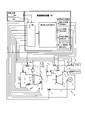
- FIG. 2 is a view showing a device configuration and handling data of the combustion control device according to the first embodiment.
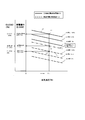
- FIG. 2 is a diagram showing an example of a database according to the first embodiment.
- FIG. 6 is a view showing a relationship between an output correction coefficient and an intake air temperature difference according to the first embodiment.
- FIG. 6 is a view showing a relationship between a pilot ratio and a turbine inlet temperature equivalent control variable according to the first embodiment.
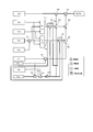
- FIG. 2 is a diagram showing control logic of the combustion control device according to the first embodiment. It is a figure which shows the control logic which concerns on the modification 1.
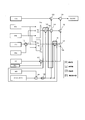
- FIG. FIG. 10 is a diagram showing control logic according to a second modification.
- FIG. 6 is a diagram showing the flow of processing of the control method according to the first embodiment.
- FIG. 6 is a view showing a device configuration and handling data of a combustion control device according to a second embodiment.
- FIG. 16 is a view showing a relationship between a turbine inlet temperature equivalent control variable (CLCSO) and a casing pressure ratio with respect to the operation mode according to the second embodiment.
- FIG. 7 is a diagram showing a flow of processing of a control method according to a second embodiment. It is a figure which shows the apparatus structure and handling data of a combustion control apparatus which concern on Embodiment 3.
- FIG. FIG. 14 is a diagram showing a flow of processing of a control method according to a third embodiment.
- the first operating mode refers to an operating mode in the normal operation where the gas turbine does not perform the anti-icing operation.
- the second operation mode is a standard operation mode of anti-icing operation in which a part of the vehicle cabin air is circulated to the intake system with a fixed extraction amount.
- the predetermined operation mode is an operation mode in which the amount of extraction necessary for stable combustion is selected in the anti-icing operation, judging from the operation situation of the gas turbine, and the extraction air is circulated to the intake facility, which is optimal for the anti-icing operation Operation mode to set various driving conditions.
- Embodiment 1 A combustion control device and a combustion control method of a gas turbine according to a first embodiment of the present invention will be described with reference to FIGS. 1 to 9.
- the apparatus configuration of the gas turbine of Embodiment 1 is shown in FIG.
- the gas turbine 1 has a compressor 2, a combustor 3, a turbine 4 and a combustion control device 50 as main components, and electric power is taken out by a generator 5 connected to a rotating shaft 8.
- the compressor 2 takes in the atmospheric air A from the intake system 7 and pressurizes and compresses it, and the compressed air A is temporarily stored in the casing 6 of the compressor 2.
- the combustor 3 mixes and burns the compressed air A and the fuel G supplied from the casing 6 to generate a high temperature combustion gas.
- the turbine 4 has a configuration in which a plurality of stages of rotor blades fixed to the rotation shaft 8 and a plurality of stages of stator vanes supported from the vehicle compartment side are alternately arranged, and introduces combustion gas generated in the combustor 3
- the rotary shaft 8 is rotated to convert thermal energy into rotational energy to drive the generator 5.
- the combustion gas discharged from the turbine 4 passes through an exhaust diffuser (not shown) and is discharged out of the system as an exhaust gas WG from the exhaust duct 13.
- the compressor 2 has an intake system 7 provided with a filter on the upstream side.
- the intake system 7 includes an intake duct 11 in which an intake filter (not shown) is incorporated.
- An intake air thermometer 34 is provided in the intake duct 11 to measure an intake air temperature 61 c and output it to the combustion control device 50.
- the compressor 2 also has a bleed pipe 12 for bleeding a part of the pressurized casing air in the casing 6 and returning it to the inlet side of the intake system 7.
- the extraction pipe 12 has an extraction flow rate meter 36 and an extraction valve 22 for measuring an extraction amount 61i (FIG. 8) of extraction air.
- the measured bleed amount 61i is output to the combustion control device 50.
- the extraction valve 22 is on / off controlled by the extraction valve opening degree command value output from the extraction valve opening degree setting unit 83 of the combustion control device 50.
- an inlet guide vane (IGV) 20 is provided on the inlet side of the compressor 2.
- the inlet guide vane (IGV) 20 is a variable vane that adjusts the amount of air flowing into the compressor 2 according to the load of the gas turbine, and the IGV opening command value from the IGV opening setting unit 82 of the combustion control device 50 Are output and controlled by the IGV drive unit 21. Furthermore, a cabin pressure gauge 31 and a cabin temperature gauge 30 are provided in the cabin 6, and output the measured cabin pressure 61p (FIG. 7) and the cabin temperature to the combustion control device 50.
- the load of the gas turbine 1 is output from the generator output detection unit 40 included in the generator 5 to the combustion control device 50 as a load value.
- the combustor 3 has a plurality of types of fuel nozzles, that is, a pilot nozzle 15 and a main nozzle 16.
- the pilot nozzle 15 is a diffusive combustion nozzle for the purpose of combustion stability in the combustor.
- the main nozzle 16 a plurality of premixed fuel nozzles disposed around the pilot nozzle 15 are used. Further, in order to NO X reduction, it may be further provided a top hat nozzles (not shown) as a kind of plural kinds of fuel nozzles.
- the fuel circuit for supplying the fuel G to the pilot nozzle 15 and the main nozzle 16 has a first fuel circuit 18 and a second fuel circuit 19, and the first fuel circuit 18 and the second fuel circuit 19 It is branch piping which branches from the fuel main circuit 17 and is connected to each nozzle.
- the first fuel circuit 18 is a pipe that branches from the fuel main circuit 17 and supplies the fuel G to the pilot nozzle 15, and a pilot fuel adjustment valve 23 is provided.
- the second fuel circuit 19 is a pipe for supplying the fuel G to the main nozzle 16, and the main fuel adjustment valve 24 is provided.
- a fuel flow meter 37 and a fuel thermometer 38 are provided in the fuel main circuit 17, and the measured value is output to the combustion control device 50.
- the pilot fuel adjustment valve 23 adjusts the flow rate of the pilot fuel supplied to the pilot nozzle 15 according to the valve opening degree command value output from the fuel valve opening degree setting unit 81 of the combustion control device 50.
- the main fuel adjustment valve 24 adjusts the flow rate of fuel supplied to the main nozzle 16 according to the valve opening degree command value output from the fuel valve opening degree setting unit 81 of the combustion control device 50.
- the combustor 3 and the turbine are disposed in the casing 6 in order to discharge the compressed air A in the casing 6 to the exhaust duct 13 for the purpose of adjusting the properties of the exhaust gas WG and the like during partial load operation of the gas turbine.
- a turbine bypass pipe 14 is provided to bypass the valve 4 and connect the passenger compartment 6 and the exhaust duct 13.
- the turbine bypass pipe 14 is provided with a turbine bypass valve 25 that adjusts a bypass amount of the compressed air A according to a turbine bypass valve opening degree command value from a turbine bypass valve opening degree setting unit 84 of the combustion control device 50.
- the temperature of the exhaust gas WG discharged from the gas turbine 1 is measured by the exhaust gas thermometer 39, and the measured value is output to the combustion control device 50.
- an atmospheric pressure gauge 33 and an atmospheric thermometer 32 for measuring the atmospheric pressure 61 k and the atmospheric temperature 61 g are disposed outside, and the measured values are output to the combustion control device 50.
- an anti-icing command value (AID), which is one of external command values instructing gas turbine load and on / off of the anti-icing operation, is output from the outside to the combustion control device 50.
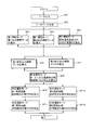
- the combustion control device 50 calculates the required fuel flow rate by calculating the turbine inlet temperature based on the input signal or the external command value and the input unit 60 receiving the input signal from each measuring meter and the external command value It comprises a setting unit 70 and a valve opening degree setting unit 80 which sets the valve opening degree of each valve based on the command value output from the fuel distribution setting unit 70.
- the combustion control device 50 is configured to have a computer. Each functional configuration of the combustion control device 50 functions by executing a program installed in an external storage device or the like of a computer.
- the valve opening setting unit 80 sets a fuel valve opening setting unit 81 that sets the opening of the pilot fuel adjusting valve 23 and the main fuel adjusting valve 24 and an IGV opening that sets the opening of the inlet guide vane (IGV) 20
- Input data 61 sent to each measuring instrument or the input unit 60 from the outside are generator output, fuel flow, combustion air flow, bleed flow, intake flow, turbine bypass flow, IGV opening, bleed valve Opening degree, turbine bypass valve opening degree, exhaust gas temperature, intake air temperature, atmospheric temperature, casing temperature, casing pressure, intake pressure, turbine output command value (MW) as atmospheric pressure and external command value, and anti-icing command value (AID) etc.
- These input signals are output to the fuel distribution setting unit 70.
- the fuel distribution setting unit 70 performs combustion based on measured values of flow rate, temperature, pressure, etc. of each part indicating the operating state of the gas turbine from the input unit 60, turbine output command value (MW) and anti-icing command value (AID).
- the combustion temperature in the unit 3 that is, the turbine inlet temperature (TIT) is calculated, and a turbine inlet temperature equivalent control variable (CLCSO) non-dimensionalized (calculated) is set based on the turbine inlet temperature (TIT).
- the turbine inlet temperature equivalent control variable (CLCSO) is proportional to the turbine inlet temperature (TIT). Also, if the IGV opening is constant, the turbine inlet temperature (TIT) is proportional to the turbine output (generator output).
- the fuel distribution ratio FDR of the fuel supplied to the various fuel nozzles is determined as a function of the turbine inlet temperature equivalent control variable (CLCSO).
- the fuel distribution ratio FDR of the pilot fuel adjustment valve 23 and the main fuel adjustment valve 24 set by the fuel distribution setting unit 70 is output to the valve opening degree setting unit 80.
- the total fuel flow rate supplied to various fuel nozzles is determined by the total fuel flow rate command value (CSO) set from the turbine output command value (MW) and the generator output etc.
- the fuel distribution ratio FDR of the fuel adjustment valve 23 and the main fuel adjustment valve 24 is determined from the turbine inlet temperature equivalent control variable (CLCSO).
- the fuel valve opening degree setting unit 81 calculates the fuel flow rate of each fuel valve based on the total fuel flow rate command value (CSO) and the fuel distribution ratio FDR of the pilot fuel adjustment valve 23 and the main fuel adjustment valve 24 and calculates each valve Calculate the Cv value of to set the valve opening degree.
- the valve opening degree command value is output to each fuel adjustment valve to control the flow rate of fuel supplied to each fuel nozzle.
- the IGV opening setting unit 82 sets the IGV opening based on the generator output 61 a and outputs the setting to the IGV driving unit 21.
- the extraction valve opening degree setting unit 83 sets the extraction valve opening degree based on the anti-icing command value (AID), and outputs it to the extraction valve 22.
- the turbine bypass valve opening setting unit 84 sets the valve opening based on the turbine bypass valve opening command value, and outputs the valve opening to the turbine bypass valve 25.
- valve opening degree setting unit 80 of the combustion control device 50 shown in FIG. 2 shows only the fuel valve opening degree setting unit 81 for the sake of convenience.
- the database 70a is created on the basis of the first operation mode in which the anti-icing operation is not performed. That is, a management parameter is selected from among various measured values and external command values indicating the operating state of the gas turbine according to the first operating mode received by input unit 60 and input data 61 of various control values, and input data 61 and separately
- the relationship between the management parameter and the turbine output (generator output MW) is constructed as the database 70a based on the data group of the accumulated various measurement values.
- a turbine inlet temperature equivalent control variable (CLCSO) is set based on the database 70a.
- a generator output 61a As the management parameters, a generator output 61a, an IGV opening 61b, an intake air temperature 61c, an intake flow rate 61d, and a turbine bypass flow rate 61e are selected. Note that the parameters listed as the management parameters are an example, and the present invention is not limited to these.
- FIG. 3 shows an example of the database 70a.
- FIG. 3 shows an example in which the generator output (MW) is shown on the vertical axis and the intake air temperature (TIN) is selected from the control parameters on the horizontal axis.
- the solid line shows the relationship between the generator output (MW) at the turbine inlet temperature (TIT) at rated load operation and the intake air temperature (TIN), and the dotted line shows the generator output at the turbine inlet temperature (TIT) at no load operation (TIT)
- TIT turbine inlet temperature
- TIT turbine inlet temperature
- TIT turbine inlet temperature
- TIT turbine inlet temperature
- TIT turbine inlet temperature
- TIT turbine inlet temperature
- TIT turbine inlet temperature
- TIT no load operation
- IGV opening indicates a three-stage valve opening of 0%, 50%, and 100%. According to FIG.
- the generator output (MW) and the turbine inlet temperature (TIT) are in a proportional relationship.
- the generator output (MW) decreases as the intake air temperature (TIN) rises. If the intake air temperature (TIN) is constant, the generator output (MW) increases as the IGV opening increases.
- the relationship between the generator output (MW) and the intake air flow rate and the turbine bypass flow rate is also included in the database 70a.
- the turbine inlet temperature equivalent control variable (CLCSO) is the generator output (first output interpolation data 71a) during no load operation in the first operation mode and the generator output (second output interpolation data during rated load operation) 71b) is calculated from the database 70a, and is interpolated by the actually-measured actual generator output 61a to calculate a turbine inlet temperature equivalent control variable (CLCSO) corresponding to the generator output 61a.
- This calculation method is disclosed in Patent Document 2 and the like.
- No-load operation refers to, for example, a case where the turbine inlet temperature is 700 ° C.
- “rated load operation” refers to, for example, when the turbine inlet temperature is 1500 ° C.
- CLCSO turbine inlet temperature equivalent control variable
- the generator output is expressed in percent (%). That is, assuming that the generator output 61a in actual operation input by the input unit 60 is AMW, the relationship between the generator output and the CLCSO is expressed by Equation (1).
- CLCSO (AMW-XMW) / (YMW-XMW) x 100 ... (1)
- the relationship between the generator output (MW) and the intake air temperature (TIN) in the case of 100% IGV opening during no-load operation is indicated by line L1, and the IGV opening is 100% during rated load operation.
- the case of driving is indicated by a line L2.
- a point corresponding to the intake air temperature (TIN) on the line L1 is set as a point X1
- a generator output at the point X1 is set as XMW.
- a point corresponding to the intake air temperature (TIN) on the line L2 is set as a point Y1
- a generator output at the point Y1 is set as YMW.
- a point corresponding to the generator output AMW during actual operation on the line segment X1Y1 is taken as a point Z1.
- the turbine inlet temperature equivalent control variable (CLCSO) at the time of actual operation corresponds to a value in which a ratio of (line segment Z1X1) / (line segment Y1X1) is expressed as a percentage (%).
- the turbine inlet temperature equivalent to the actual operation Control variables (CLCSO) can be calculated.
- the CLCSO in the actual operation can be calculated by changing the intake temperature (TIN) and the IGV opening and selecting a value corresponding to the actual operation output (AMW).
- the line indicated by an alternate long and short dash line represents the relationship between the generator output (MW) and the intake air temperature (TIN) at a predetermined turbine inlet temperature during actual operation at an IGV opening of 100%, assuming a predetermined operation mode. And are displayed for reference.
- the above explanation is a method of calculating the turbine inlet temperature equivalent control variable (CLCSO) at a specific intake air temperature and IGV opening degree, calculation is performed by the same method even if other intake air temperature and IGV opening degree are selected. it can.
- the time of a rated load operation and the time of no load operation were taken up as turbine inlet temperature, these temperatures are an example, Comprising: It is not limited to these temperatures.
- the fuel distribution setting unit 70 in the present embodiment includes an output interpolation data calculation unit 71, an output interpolation data correction unit 72, a control variable calculation unit 75, and a fuel distribution calculation unit 76.
- the determination as to whether or not to start the anti-icing operation depends on the atmospheric temperature 61g, and when the atmospheric temperature 61g becomes lower than a predetermined value, the external anti-icing command value (AID) is externally input to the combustion control device 50 .
- the output interpolation data calculation unit 71 is a part of a preparation stage for correcting the operating conditions.
- the turbine output (generator output) during no-load operation of the gas turbine is calculated as the first output interpolation data 71a from the database 70a, and the turbine output (generator output) during rated load operation of the gas turbine is second-output interpolation It is calculated as data 71 b, and any data is output to the output interpolation data correction unit 72.
- the output interpolation data correction unit 72 includes a correction coefficient calculation unit 73 and an output interpolation data correction unit 74.
- the specific parameter that affects the stability of the combustion control in the anti-icing operation is selected in advance.
- the output interpolation data correction unit 72 corrects the first output interpolation data 71a and the second output interpolation data 71b based on the selected specific parameter, and sets the first correction output interpolation data 74a and the second correction output interpolation data 74b. Have the ability to
- the correction coefficient calculation unit 73 has a function of selecting an output correction coefficient F for a specific parameter in order to correct the first output interpolation data 71a and the second output interpolation data 71b transmitted from the output interpolation data calculation unit 71.
- the stability of combustion control depends on the amount of bleed air. Therefore, as the specific parameters, in addition to the intake temperature difference 61f and the compartment pressure ratio 61h, which are largely affected by the amount of extraction, the opening degree 61m of the extraction valve and the extraction amount 61i itself can be selected.
- the intake air temperature difference 61 f refers to the difference between the intake air temperature 61 c on the inlet side of the intake system 7 and the air temperature 61 g.
- the casing pressure ratio 61h refers to the ratio of the casing pressure 61p to the atmospheric pressure 61k (casing pressure 61p / atmospheric pressure 61k).
- FIG. 4 shows the relationship between the intake air temperature difference ( ⁇ T) shown on the horizontal axis and the output correction coefficient F shown on the vertical axis.
- ⁇ T intake air temperature difference
- the output correction coefficient F tends to decrease as the intake air temperature difference ( ⁇ T) increases.
- the intake air temperature difference ( ⁇ T) becomes zero, and the output correction coefficient F becomes 1.0.
- other specific parameters case pressure ratio, opening degree of extraction valve, extraction amount
- the output interpolation data correction unit 74 corrects the first output interpolation data 71a and the second output interpolation data 71b based on the output correction coefficient F selected by the correction coefficient calculation unit 73 to obtain the first corrected output interpolation data 74a and It has a function of calculating the second corrected output interpolation data 74b. That is, the first corrected output interpolation data 74a is calculated by multiplying the first output interpolation data 71a by the output correction coefficient F. Similarly, the second corrected output interpolation data 74b is calculated by multiplying the second output interpolation data 71b by the output correction coefficient F.
- the first corrected output interpolation data 74 a and the second corrected output interpolation data 74 b are output to the control variable calculation unit 75.
- the control variable calculation unit 75 has a function of calculating a turbine inlet temperature equivalent control variable (CLCSO) using the first corrected output interpolation data 74a and the second corrected output interpolation data 74b corrected by the intake air temperature difference 61f. That is, instead of the first output interpolation data 71a and the second output interpolation data 71b described above, the first correction output interpolation data 74a corresponding to the no load operation output and the second correction output interpolation corresponding to the rated load operation output Using the data 74b, the turbine inlet temperature equivalent control variable (CLCSO) is calculated by interpolation with the turbine output (generator output MW) 61a during actual operation according to the above-mentioned equation (1). The calculated turbine inlet temperature control variable (CLCSO) is output to the fuel distribution calculation unit 76.
- CLCSO turbine inlet temperature equivalent control variable
- the fuel distribution calculation unit 76 has a function of setting the fuel distribution of each fuel nozzle based on the turbine inlet temperature equivalent control variable (CLCSO).
- FIG. 5 shows the relationship between the pilot ratio PR and the turbine inlet temperature equivalent control variable (CLCSO).
- the pilot ratio PR can be determined based on the turbine inlet temperature equivalent control variable (CLCSO) calculated by the control variable calculation unit 75. That is, the pilot ratio PR is a ratio (%) of the fuel distribution ratio FDR to the total fuel flow rate of the fuel supplied to the first fuel circuit 18 connected to the pilot nozzle 15, and the main ratio MR is the total fuel The value obtained by subtracting the pilot ratio PR from the flow rate is shown as a percentage (%) to the total fuel flow rate.
- the main ratio MR refers to the fuel distribution ratio FDR of the second fuel circuit 19 connected to the main nozzle 16.
- the fuel distribution ratio FDR of each of the first fuel circuit 18 and the second fuel circuit 19 determined by the fuel distribution calculation unit 76 is output to the fuel valve opening degree setting unit 81.
- the fuel valve opening setting unit 81 of the valve opening setting unit 80 is based on the fuel distribution ratio FDR sent from the fuel distribution calculating unit 76 and the total fuel flow rate command value (CSO) separately set by the fuel distribution setting unit 70. , And has a function of setting the opening degree of each fuel control valve. That is, the pilot fuel adjustment valve 23 calculates the flow rate of fuel supplied to the pilot nozzle 15 based on the total fuel flow rate command value (CSO) and the fuel allocation ratio FDR of the first fuel circuit 18. Calculate the Cv value and set the valve opening degree. Similarly, for the main fuel adjustment valve 24, the valve opening degree can be set from the total fuel flow rate command value (CSO) and the fuel distribution ratio FDR of the second fuel circuit 19.
- the valve opening degree command value PVS of the pilot fuel adjustment valve 23 and the valve opening degree instruction value MVS of the main fuel adjustment valve 24 set by the valve opening degree setting unit 80 are respectively set to the pilot fuel adjustment valve 23 and the main fuel adjustment valve 24. It is output.
- a top hat nozzle (not shown) is used, as with the pilot nozzle, the top hat fuel adjustment valve (not shown) is opened based on the relationship between the top hat ratio and the turbine inlet temperature equivalent control variable (CLCSO). You can set the degree.
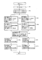
- control logic of the combustion control device of the present embodiment will be described using FIG.
- the control logic shown in FIG. 6 is based on the control logic for calculating CLCSO shown in Patent Document 2, and adds logic for correcting the output based on the output correction coefficient F.
- AID anti-icing command value
- CLCSO turbine inlet temperature equivalent control variable
- the present embodiment is an example in which the correction is performed using the intake air temperature difference 61f as the specific parameter.
- the turbine inlet temperature equivalent control variable (CLCSO) is corrected by the output correction coefficient F.
- CLCSO turbine inlet temperature equivalent control variable
- the signal of the on of the anti-icing command value (AID) is multiplied by the multiplier 115.
- the subtractor 114 subtracts the atmospheric temperature 61g from the intake air temperature 61c to calculate an intake air temperature difference 61f.
- the function generator 116 calculates the output correction coefficient F based on the intake air temperature difference 61f.
- the first function generator 111 and the second function generator 112 The output interpolation data 71a and the second output interpolation data 71b related to the output under rated load operation are generated.
- the multiplier 118 multiplies the calculated first output interpolation data 71a by the output correction coefficient F to calculate the corrected first corrected output interpolation data 74a.
- the second output interpolation data 71b is multiplied by the output correction coefficient F to calculate the second corrected output interpolation data 74b after correction.
- a turbine inlet temperature equivalent control variable (CLCSO) is calculated based on the first corrected output interpolation data 74a and the second corrected output interpolation data 74b.
- CLCSO turbine inlet temperature equivalent control variable
- FIG. 7 shows a modification 1 of the control logic shown in FIG.
- the modified example 1 is an example in which a cabin pressure ratio is applied as a specific parameter. That is, when the gas turbine is introduced into the anti-icing operation, the signal of the on of the anti-icing command value (AID) is multiplied by the multiplier 132.
- a casing pressure ratio 61h casing pressure 61p / atmospheric pressure 61k
- a function generator 133 calculates an output correction coefficient F.
- multipliers 134 and 135 multiply the first output interpolation data 71a and the second output interpolation data 71b by the calculated output correction coefficient F.
- FIG. 8 shows a second modification in which the extraction amount 61i or the extraction valve opening 61m is selected as the specific parameter.
- the signal of the anti-icing command value (AID) on is multiplied by the multiplier 141.
- the function generator 142 calculates the output correction coefficient F from the extraction amount 61i or the extraction valve opening 61m.
- the multipliers 143 and 144 respectively multiply the first output interpolation data 71a and the second output interpolation data 71b by the calculated output correction coefficient F.
- the following method of calculating the turbine inlet temperature equivalent control variable (CLCSO) is the same as the method described in Patent Document 2 and the like.
- the part except the control logic enclosed by the thick line frame is the same structure as Embodiment 1, it uses the same name and code and abbreviate
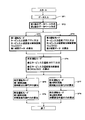
- the measured values, the various valve openings, and the external command value are transmitted to the input unit 60, and are output as the input data 61 to the fuel distribution setting unit 70 (SP1).
- the fuel distribution setting unit 70 creates the relationship between the management parameter and the turbine output (generator output MW) as the database 70a based on the input data 61 received by the input unit 60 (SP2 ).
- the output interpolation data calculation unit 71 calculates the first output interpolation data 71a during no-load operation and the second output interpolation data 71b during rated load operation (SP3, SP4).
- the correction coefficient calculation unit 73 calculates an intake air temperature difference 61f based on the intake air temperature 61c and the air temperature 61g transmitted from the input unit 60, and calculates an output correction coefficient F based on the calculated intake air temperature difference 61f (SP5) ).
- the cabin pressure ratio 61h is calculated from the cabin pressure 61p and the atmospheric pressure 61k instead of the intake temperature 61c and the atmospheric temperature 61g described above, and output The correction coefficient F is calculated.
- the output correction coefficient F is calculated from the extraction amount 61i or the extraction valve opening degree 61m.
- the output interpolation data correction unit 74 multiplies the first output interpolation data 71a and the second output interpolation data 71b calculated by the output interpolation data calculation unit 71 and the output correction coefficient F calculated by the correction coefficient calculation unit 73. Then, the first corrected output interpolation data 74a and the second corrected output interpolation data 74b are calculated (SP6, SP7).
- turbine output in a predetermined operation (actual operation) mode based on the first corrected output interpolation data 74a and the second corrected output interpolation data 74b output from the output interpolation data correction unit 74.
- the turbine inlet temperature equivalent control variable (CLCSO) in the predetermined operation mode is determined using 61a (SP8).
- the fuel distribution calculation unit 76 uses the relationship between the pilot ratio PR and the turbine inlet temperature equivalent control variable (CLCSO) shown in FIG. 5 to generate the first fuel circuit 18 and the second fuel in the predetermined operation (actual operation) mode.
- the fuel distribution ratio FDR related to the circuit 19 is calculated. That is, based on corrected output interpolation data (first corrected output interpolation data 74a, second corrected output interpolation data 74b) obtained by correcting the output interpolation data (first output interpolation data 71a, second output interpolation data 71b) during normal operation.
- the pilot ratio PR that is, the fuel distribution ratio FDR of the first fuel circuit 18 is calculated from the relationship of FIG. 5 (SP9).
- the fuel distribution ratio FDR of the second fuel circuit 19 can be calculated by subtracting the fuel distribution ratio FDR of the first fuel circuit 18 assuming that the total fuel flow rate is 1 (100%) (SP10).
- valve opening degree setting unit 81 of the valve opening degree setting unit 80 based on the fuel distribution ratio FDR of each of the first fuel circuit 18 and the second fuel circuit 19 calculated by the fuel distribution calculation unit 76, The valve opening degree of the fuel adjustment valve 23 and the main fuel adjustment valve 24 is set.
- the respective valve opening degree command values PVS, MVS are output to the pilot fuel adjustment valve 23 and the main fuel adjustment valve 24 (SP11, SP12).
- the generator output is maintained with respect to the increase in the amount of extraction, and the turbine inlet temperature equivalent control variable (CLCSO) Is properly corrected, and stable combustion control can be maintained.
- CLCSO turbine inlet temperature equivalent control variable
- stable operation of the gas turbine can be performed while satisfying emission control values such as NO x and CO even during turn-down operation.
- the first database 90a relating to the first operation mode and the second database 90b relating to the second operation mode are prepared, and based on these databases, the control corresponding to the corrected turbine inlet temperature in the predetermined operation (actual operation) mode
- the point of calculating the variable (MCLCSO) is different from that of the first embodiment. That is, in the first embodiment, the database 70a refers to only the first operation mode, but in the second embodiment, the database 90a differs in that it refers to the databases 90a and 90b in both the first operation mode and the second operation mode. .
- fuel distribution setting unit 90 based on input data 61 of each measured value output from input unit 60 and an external command value (output command value (MW), anti-icing command value (AID)).
- MW output command value
- AID anti-icing command value
- the relationship between the management parameter and the turbine output (generator output MW) is created as a first database 90a according to the first operation mode and a second database 90b according to the second operation mode, respectively.
- the configuration of each database in the present embodiment is the same as that of the first embodiment.
- the combustion control device 50 in the present embodiment is the same as that of the first embodiment in that the combustion control device 50 is configured by the input unit 60, the fuel distribution setting unit 90, and the valve opening degree setting unit 80. It differs from the first embodiment. That is, the fuel distribution setting unit 90 includes a turbine inlet temperature equivalent control variable setting unit 91 and a fuel distribution correction unit 92.
- the turbine inlet temperature equivalent control variable setting unit 91 has a function of calculating a turbine inlet temperature equivalent control variable (CLCSO) according to the first operation mode and the second operation mode. That is, the first output interpolation data 91a in no load operation and the second output interpolation data 91b in rated load operation are calculated from the first database 90a in the first operation mode. Further, third output interpolation data 91c during no-load operation and fourth output interpolation data 91d during rated load operation are similarly calculated from the second database 90b according to the second operation mode.
- CLCSO turbine inlet temperature equivalent control variable
- first interpolation data 91e corresponding to the turbine inlet temperature equivalent control variable (CLCSO1) in the first operation mode is calculated from the first output interpolation data 91a and the second output interpolation data 91b according to the first operation mode.
- second interpolation data 91f corresponding to a turbine inlet temperature equivalent control variable (CLCSO2) in the second operation mode is calculated from the third output interpolation data 91c and the fourth output interpolation data 91d according to the second operation mode.
- the procedure for calculating the first interpolation data 91e and the second interpolation data 91f from the databases 90a and 90b in each of the first operation mode and the second operation mode is the same as the procedure described in the first embodiment. .
- the first interpolation data 91 e and the second interpolation data 91 f thus calculated are output to the control variable interpolation unit 93 of the fuel distribution correction unit 92.
- the fuel distribution correction unit 92 corrects the turbine inlet temperature control variables (CLCSO1 and CLCSO2) calculated by the turbine inlet temperature equivalent control variable setting unit 91 to calculate a corrected turbine inlet temperature equivalent control variable (MCLCSO).
- the fuel distribution calculation unit 94 includes the interpolation unit 93 and the fuel distribution ratio FDR of each of the fuel circuits 18 and 19 from the corrected turbine inlet temperature equivalent control variable (MCLCSO).
- control variable interpolation unit 93 sets the first interpolation data 91 e corresponding to the turbine inlet temperature control variable (CLCSO1) according to the first operation mode transmitted from the turbine inlet temperature equivalent control variable setting unit 91 to the second operation mode. It has a function of calculating a corrected turbine inlet temperature equivalent control variable (MCLCSO) in the predetermined operation (actual operation) mode based on the second interpolation data 91f corresponding to the turbine inlet temperature control variable (CLCSO2).
- MCLCSO turbine inlet temperature equivalent control variable
- FIG. 11 shows the relationship between the turbine inlet temperature equivalent control variable (CLCSO) and the cabin pressure ratio (CPR) in each operation mode when the cabin pressure ratio is selected as the specific parameter.
- the vertical axis represents the turbine inlet temperature control variable (CLCSO), and the horizontal axis represents the cabin pressure ratio (CPR).
- CLCSO turbine inlet temperature control variable
- CPR cabin pressure ratio
- turbine inlet temperature (TIT) is proportional to turbine output (generator output MW). Further, if the IGV opening is constant, the turbine inlet temperature (TIT) is also proportional to the cabin pressure ratio (CPR). Furthermore, the turbine inlet temperature equivalent control variable (CLCSO) is a value obtained by dimensioning the turbine inlet temperature (TIT) as described above. That is, if the IGV opening is constant, the turbine inlet temperature equivalent control variable (CLCSO) is in proportion to the casing pressure ratio (CPR) and the turbine output (generator output MW). That is, as shown in FIG. 11, the relationship between the turbine inlet temperature equivalent control variable (CLCSO) and the casing pressure ratio (CPR) is represented by a linear relationship if the IGV opening is constant.
- the first operation mode is indicated by a dotted line as line L1
- the second operation mode is indicated by a solid line as line L2.
- the turbine inlet temperature equivalent control variable (CLCSO) becomes higher than in the normal operation (first operation mode) in which the anti-icing operation is not performed. That is, if the casing pressure ratio does not change, the turbine inlet temperature equivalent control variable (CLCSO) is higher in the second operation mode than in the first operation mode.
- turbine inlet temperature equivalent control variables (CLCSO) in the respective operation modes are set as CLCSO1 and CLCSO2 .
- a point on the line L1 with respect to the casing pressure ratio (CP1) in the first operation mode is a point P
- a point on the line L2 with respect to the casing pressure ratio (CP2) in the second operation mode is a point Q
- the points P and Q corresponds to CLCSO1 and CLCSO2.
- the pressure ratio CPS in the predetermined operation (actual operation) mode is set, and a point corresponding to the pressure ratio CPS in the line L3 connecting the points P and Q on the lines L1 and L2 is set as a point S.
- the turbine inlet temperature equivalent control variable corresponding to the point S is CLCSOS
- this value corresponds to the corrected turbine inlet temperature equivalent control variable (MCLCSO) in the predetermined operation (actual operation) mode. That is, the relationship between the turbine inlet temperature equivalent control variables CLCSO1, CLCSO2, and CLCSOS and the casing pressure ratios CP1, CP2, and CPS is expressed by Equation (2).
- CLCSOS CLCSO1 + (CLCSO2-CLCSO1) * (CPS-CP1) / (CP2-CP1) (2)
- the cabin pressure ratio (CP1) in the first operation mode from the cabin pressure ratio (CP1) in the first operation mode, the cabin pressure ratio (CP2) in the second operation mode, and the cabin pressure ratio (CPS) in the predetermined operation (actual operation) mode, the first operation mode and the second operation
- CLCSO1, CLCSO2 turbine inlet temperature equivalent control variables
- CLCSOS turbine inlet temperature equivalent control variable
- the turbine inlet temperature equivalent control variable (CLCSOS) corresponds to the corrected turbine inlet temperature equivalent control variable (MCLCSO) in the predetermined operation (actual operation) mode.
- the present invention is not limited to this, and for example, even when the cabin pressure ratio (CPS) is smaller than the cabin pressure ratio (CP2), the extrapolation method is used.
- a linear interpolation method can be applied to similarly calculate a corrected turbine inlet temperature equivalent control variable (MCLCSO) in a predetermined operation mode.
- the fuel distribution calculation unit 94 uses the corrected turbine inlet temperature equivalent control variable (MCLCSO) calculated by the control variable interpolation unit 93, the fuel distribution calculation unit 94 relates to the first fuel circuit 18 and the second fuel circuit 19 in the predetermined operation mode.
- the fuel distribution ratio FDR is calculated.
- the calculation procedure of the fuel distribution ratio FDR is the same as the method described with reference to FIG. 5 of the first embodiment, and thus the details will be omitted.
- the calculated fuel distribution ratio FDR of the first fuel circuit 18 and the second fuel circuit 19 is output to the fuel valve opening setting unit 81 of the valve opening setting unit 80.
- the fuel valve opening degree setting unit 81 sets the valve opening degree of the pilot fuel adjusting valve 23 of the first fuel circuit 18 and the main fuel adjusting valve 24 of the second fuel circuit 19.
- the setting procedure of the valve opening degree of each valve is the same as that of Embodiment 1, and the details will be omitted.
- the determined valve opening degree is output to the pilot fuel adjustment valve 23 and the main fuel adjustment valve 24.
- a valve-opening degree can be set in the procedure similar to a pilot fuel adjustment valve.
- the measured values, the various valve openings, and the external command value are transmitted to the input unit 60, and are output as the input data 61 to the fuel distribution setting unit 90 (SP1).
- the fuel distribution setting unit 90 creates the relationship between the management parameter and the turbine output (generator output MW) as the database 90a and the database 90b (SP2).
- Databases 90a and 90b according to the first operation mode and the second operation mode are respectively referred to as a first database 90a and a second database 90b.
- the cabin pressure ratio (CPR) is shown as a representative example as the specific parameter to be selected, but other specific parameters can also be applied as in the first embodiment.
- first output interpolation data 91a at no load operation and the second output interpolation data 91b at rated load operation are calculated (SP3).
- first interpolation data 91e corresponding to the turbine inlet temperature equivalent control variable (CLCSO1) in the first operation mode is calculated based on the first output interpolation data 91a and the second output interpolation data 91b (SP4).
- the procedure for calculating the turbine inlet temperature equivalent control variable (CLCSO) from the database is the same method as the procedure described in the first embodiment.
- third output interpolation data 91c in no-load operation and fourth output interpolation data 91d in rated load operation are calculated using the second database 90b in the second operation mode (SP5). Further, based on the third output interpolation data 91c and the fourth output interpolation data 91d, second interpolation data 91f corresponding to the turbine inlet temperature equivalent control variable (CLCSO2) in the second operation mode is calculated (SP6).
- CLCSO2 turbine inlet temperature equivalent control variable
- a corrected turbine inlet temperature equivalent control variable (MCLCSO) in the predetermined operation (actual operation) mode is calculated (SP7 ). Interpolation is performed based on the turbine inlet temperature equivalent control variable (CLCSO1) and the casing pressure ratio (CP1) in the first operation mode, and the turbine inlet temperature equivalent control variable (CLCSO2) and the casing pressure ratio (CP2) in the second operation mode.
- the procedure for interpolating and calculating the corrected turbine inlet temperature equivalent control variable (MCLCSO) in the predetermined operation (actual operation) mode is the same as the procedure described with reference to FIG.
- the fuel allocation ratio FDR of the first fuel circuit 18 and the second fuel circuit 19 is calculated based on the corrected turbine inlet temperature equivalent control variable (MCLCSO) in the predetermined operation (actual operation) mode (SP8, SP9).
- MCLCSO corrected turbine inlet temperature equivalent control variable
- SP8 SP9 the valve opening degree PVS of the pilot fuel adjusting valve 23 of the first fuel circuit 18 and the main fuel adjusting valve 24 of the second fuel circuit 19 , MVS can be selected (SP10, SP11).
- the turbine inlet temperature equivalent control variable (CLCSO) is calculated by interpolating the database during anti-icing operation and the database during normal operation, as compared to the first embodiment.
- the turbine inlet temperature equivalent control variable (CLCSO) can be set more accurately than in the first embodiment. Therefore, even when anti-icing operation is started, more stable combustion control can be realized.
- stable operation of the gas turbine can be performed while satisfying emission control values such as NO x and CO even during turn-down operation.
- Embodiment 1 and Embodiment 2 convert the turbine output (generator output MW) or the relation between the turbine inlet temperature and the management parameter into a database based on the input data (input data group) 61 transmitted from the input unit 60. Based on this database, the fuel distribution ratio of the fuel circuit was set, and the valve opening was set.
- the relationship between the turbine inlet temperature (TIT) and the input data 61 is put into a database without using management parameters, and the valve opening degree of each valve is set based on this database. This is different from 1 and Embodiment 2.
- the target calculated from the data base includes the turbine inlet temperature (TIT) in addition to the turbine inlet temperature equivalent control variable (CLCSO), as described above, the turbine inlet temperature (TIT) Because the turbine inlet temperature equivalent control variable (CLCSO) is in a proportional relationship, it is possible to replace the turbine inlet temperature equivalent control variable (CLCSO) with a turbine inlet temperature (TIT).
- TIT turbine inlet temperature
- CLCSO turbine inlet temperature equivalent control variable
- the fuel distribution setting unit 100 sets the turbine inlet temperature (TIT) and the input data 61 as a preparation step.
- TIT turbine inlet temperature
- the turbine inlet temperature equivalent control variable setting unit 101 has a function of setting interpolation data 101a and 101b corresponding to the turbine inlet temperature (TIT) or the turbine inlet temperature equivalent control variable (CLCSO) in the first operation mode and the second operation mode.
- the first interpolation data 101a corresponding to the turbine inlet temperature (TIT1) or the turbine inlet temperature equivalent control variable (CLCSO1) in the first operation mode is calculated based on the first comprehensive database 100a according to the first operation mode.
- second interpolation data 101b corresponding to the turbine inlet temperature (TIT2) or the turbine inlet temperature equivalent control variable (CLCSO2) in the second operation mode is calculated. These data are output to the control variable interpolation unit 103 of the fuel distribution correction unit 102.
- the control variable interpolation unit 103 corrects the corrected turbine inlet temperature in the predetermined operation (actual operation) mode based on the first interpolation data 101a and the second interpolation data 101b output from the turbine inlet temperature equivalent control variable setting unit 101. It has a function to set MTIT) or a modified turbine inlet temperature equivalent control variable (MCLCSO). Specifically, based on the first interpolation data 101a in the first operation mode and the second interpolation data 101b in the second operation mode, using a specific parameter, the corrected turbine inlet temperature (MTIT) in the predetermined operation (actual operation) mode or The corrected turbine inlet temperature equivalent control variable (MCLCSO) is calculated.
- the specific parameter is, for example, a cabin pressure ratio (CPR).
- the linear interpolation method by the interpolation method or the extrapolation method described using FIG. Applicable When FIG. 11 of the second embodiment is applied to the present embodiment, the turbine inlet temperature equivalent control variable (CLCSO) on the vertical axis may be replaced with the turbine inlet temperature (TIT). Also, as a specific parameter, another specific parameter may be applied instead of the cabin pressure ratio (CPR).
- CPR cabin pressure ratio
- the fuel distribution calculation unit 104 uses the first fuel circuit in the predetermined operation (actual operation) mode.
- the fuel distribution ratio FDR related to the 18 and the second fuel circuit 19 is calculated.
- the calculation procedure of the fuel distribution ratio FDR is the same as that of the first embodiment, and thus the details will be omitted.
- the calculated fuel distribution ratio FDR of the first fuel circuit 18 and the second fuel circuit 19 is output to the fuel valve opening setting unit 81 of the valve opening setting unit 80.
- the fuel valve opening degree setting unit 81 sets the valve opening degree of the pilot fuel adjustment valve 23 of the first fuel circuit 18 and the main fuel adjustment valve 24 of the second fuel circuit 19.
- the setting procedure of the valve opening degree of each valve is the same as in the first embodiment.
- the set valve opening degree command values PVS and MVS are output to the pilot fuel adjustment valve 23 and the main fuel adjustment valve 24.
- FIG. 1 The flow of processing different from the methods of Embodiments 1 and 2 is indicated by thick-lined blocks.
- the relationship between the turbine inlet temperature (TIT) and the input data group is made into a database for each of the first operation mode and the second operation mode (a first comprehensive database 100a, a second comprehensive database Database 100b).
- the first interpolation data 101a and the second interpolation data 101b related to the turbine inlet temperature (TIT) or the turbine inlet temperature equivalent control variable (CLCSO) are calculated, and from these data, the corrected turbine inlet temperature (MTIT) Or a modified turbine inlet temperature equivalent control variable (MCLCSO) is different from that of the second embodiment.
- the flow of the other processing is the same as that of the second embodiment.
- combustion control can be performed more stably than in the first and second embodiments. That is, in the case of the present embodiment, measurement values, control values, and external command values in a wider range than those in the first and second embodiments are captured and made into a database. Thus, higher accuracy is better set the turbine inlet temperature (TIT) or turbine inlet temperature corresponding control variable (CLCSO) is, since the fuel valve opening can be determined, unstable combustion state is eliminated, NO X and the combustion vibration The problem is also solved.
- TIT turbine inlet temperature
- CLCSO turbine inlet temperature corresponding control variable
- stable operation of the gas turbine can be performed while satisfying emission control values such as NO x and CO even during turn-down operation.
- combustion control device and combustion control method and program of the gas turbine of the present invention even when switching from normal operation to the anti-icing operation, stable combustion control of the combustor is maintained, it can avoid an increase etc. of the NO X Also, the occurrence of combustion vibration can be suppressed. As a result, stable operation of the gas turbine is possible. Furthermore, in turn-down operation (partial load operation), stable operation is possible while satisfying the emission control value.
Landscapes
- Engineering & Computer Science (AREA)
- Chemical & Material Sciences (AREA)
- Combustion & Propulsion (AREA)
- Mechanical Engineering (AREA)
- General Engineering & Computer Science (AREA)
- Physics & Mathematics (AREA)
- Fluid Mechanics (AREA)
- Control Of Turbines (AREA)
Priority Applications (5)
| Application Number | Priority Date | Filing Date | Title |
|---|---|---|---|
| DE112015001394.6T DE112015001394B4 (de) | 2014-03-25 | 2015-03-24 | Gasturbinenverbrennungssteuervorrichtung, Verbrennungssteuerverfahren und Programm dafür |
| US15/125,331 US10208678B2 (en) | 2014-03-25 | 2015-03-24 | Gas turbine combustion control device and combustion control method and program therefor |
| CN201580014883.4A CN106103942B (zh) | 2014-03-25 | 2015-03-24 | 燃气涡轮的燃烧控制装置、燃烧控制方法 |
| KR1020167025666A KR101775861B1 (ko) | 2014-03-25 | 2015-03-24 | 가스 터빈의 연소 제어 장치 및 연소 제어 방법 및 프로그램 |
| US15/278,395 US10221777B2 (en) | 2014-03-25 | 2016-09-28 | Gas turbine combustion control device and combustion control method and program therefor |
Applications Claiming Priority (2)
| Application Number | Priority Date | Filing Date | Title |
|---|---|---|---|
| JP2014061915A JP6257035B2 (ja) | 2014-03-25 | 2014-03-25 | ガスタービンの燃焼制御装置および燃焼制御方法並びにプログラム |
| JP2014-061915 | 2014-03-25 |
Related Child Applications (2)
| Application Number | Title | Priority Date | Filing Date |
|---|---|---|---|
| US15/125,331 A-371-Of-International US10208678B2 (en) | 2014-03-25 | 2015-03-24 | Gas turbine combustion control device and combustion control method and program therefor |
| US15/278,395 Continuation-In-Part US10221777B2 (en) | 2014-03-25 | 2016-09-28 | Gas turbine combustion control device and combustion control method and program therefor |
Publications (1)
| Publication Number | Publication Date |
|---|---|
| WO2015146994A1 true WO2015146994A1 (ja) | 2015-10-01 |
Family
ID=54195506
Family Applications (1)
| Application Number | Title | Priority Date | Filing Date |
|---|---|---|---|
| PCT/JP2015/058950 WO2015146994A1 (ja) | 2014-03-25 | 2015-03-24 | ガスタービンの燃焼制御装置および燃焼制御方法並びにプログラム |
Country Status (6)
Cited By (4)
| Publication number | Priority date | Publication date | Assignee | Title |
|---|---|---|---|---|
| EP3101250A1 (de) * | 2015-06-03 | 2016-12-07 | Siemens Aktiengesellschaft | Betrieb einer gasturbine mit einer interpolierten fahrlinienabweichung |
| KR20170003288U (ko) * | 2016-03-14 | 2017-09-22 | 한국서부발전 주식회사 | 가스 및 경유 혼소 발전소의 제어 장치 |
| CN108779715A (zh) * | 2016-03-09 | 2018-11-09 | 三菱日立电力系统株式会社 | 燃气轮机的控制装置以及燃气轮机的控制方法 |
| CN112943452A (zh) * | 2021-02-23 | 2021-06-11 | 国电环境保护研究院有限公司 | 一种燃机侧控制燃气机组运行全过程nox排放的系统 |
Families Citing this family (18)
| Publication number | Priority date | Publication date | Assignee | Title |
|---|---|---|---|---|
| JP6173367B2 (ja) | 2015-02-03 | 2017-08-02 | 三菱日立パワーシステムズ株式会社 | 状態判定装置、運転制御装置、ガスタービン及び状態判定方法 |
| JP5989218B1 (ja) * | 2015-11-18 | 2016-09-07 | 東芝プラントシステム株式会社 | 発電プラントにおける空気循環制御装置および空気循環制御方法 |
| CN109072783B (zh) * | 2016-02-26 | 2021-08-03 | 八河流资产有限责任公司 | 用于控制发电设备的系统和方法 |
| JP6786233B2 (ja) * | 2016-03-22 | 2020-11-18 | 三菱パワー株式会社 | ガスタービンの特性評価装置及びガスタービンの特性評価方法 |
| JP6763629B2 (ja) * | 2016-12-15 | 2020-09-30 | 三菱パワー株式会社 | ガスタービン制御装置、ガスタービン制御方法 |
| JP6935327B2 (ja) * | 2017-12-28 | 2021-09-15 | 三菱パワー株式会社 | 制御装置、ガスタービン、制御方法及びプログラム |
| US11248525B2 (en) * | 2019-02-05 | 2022-02-15 | Pratt & Whitney Canada Corp. | System and method for detecting inlet temperature distortion of an engine |
| CN110094267B (zh) * | 2019-06-04 | 2024-11-29 | 江苏蓝芯航空航天科技有限公司 | 一种微小型航空涡轮发动机高空燃油供油系统 |
| US11535386B2 (en) | 2019-06-17 | 2022-12-27 | Pratt & Whitney Canada Corp. | System and method for operating a multi-engine rotorcraft for ice accretion shedding |
| JP7252861B2 (ja) * | 2019-08-22 | 2023-04-05 | 三菱重工業株式会社 | ガスタービンの燃焼制御装置、燃焼制御方法及びプログラム |
| DE112021005653T5 (de) * | 2020-10-26 | 2023-08-17 | Mitsubishi Heavy Industries, Ltd. | Gasturbinenleistungs-korrekturverfahren, steuerverfahren, vorrichtungzum ausführen dieser verfahren und programm, das computer veranlasst, dieseverfahren auszuführen |
| CN116490675A (zh) * | 2020-10-30 | 2023-07-25 | 三菱重工业株式会社 | 燃气涡轮的最大输出制作方法、燃气涡轮的控制用输出制作方法、燃气涡轮的控制方法、执行这些方法的装置及使计算机执行这些方法的程序 |
| US12158114B2 (en) * | 2021-04-29 | 2024-12-03 | Ge Infrastructure Technology Llc | Dispatch advisor for operating power plant with flexibility |
| WO2022252294A1 (zh) * | 2021-06-02 | 2022-12-08 | 烟台杰瑞石油装备技术有限公司 | 涡轮压裂系统及其控制方法、控制设备和存储介质 |
| US20250215834A1 (en) * | 2022-04-20 | 2025-07-03 | Mitsubishi Heavy Industries, Ltd. | Gas turbine control device, gas turbine control method, and gas turbine control program |
| JP2023166083A (ja) * | 2022-05-09 | 2023-11-21 | 三菱重工業株式会社 | ガスタービン制御装置、ガスタービン制御方法、及びプログラム |
| JP2025034955A (ja) * | 2023-08-31 | 2025-03-13 | 三菱重工業株式会社 | ガスタービン制御装置、ガスタービン制御入力決定方法及びガスタービン制御入力決定プログラム |
| JP2025036788A (ja) * | 2023-09-05 | 2025-03-17 | 三菱重工業株式会社 | ガスタービン制御装置、及び、ガスタービン制御方法 |
Citations (5)
| Publication number | Priority date | Publication date | Assignee | Title |
|---|---|---|---|---|
| JPH08178290A (ja) * | 1994-12-20 | 1996-07-12 | Toshiba Corp | ガスタービン燃料供給装置 |
| JP2004116384A (ja) * | 2002-09-26 | 2004-04-15 | Mitsubishi Heavy Ind Ltd | ガスタービン燃焼制御装置 |
| JP2007077867A (ja) * | 2005-09-14 | 2007-03-29 | Mitsubishi Heavy Ind Ltd | ガスタービンの燃焼制御装置 |
| JP2013053552A (ja) * | 2011-09-02 | 2013-03-21 | Mitsubishi Heavy Ind Ltd | ガスタービン及びガスタービンの燃焼制御方法 |
| JP2013209917A (ja) * | 2012-03-30 | 2013-10-10 | Mitsubishi Heavy Ind Ltd | ガスタービンおよびその制御方法 |
Family Cites Families (19)
| Publication number | Priority date | Publication date | Assignee | Title |
|---|---|---|---|---|
| US5560195A (en) | 1995-02-13 | 1996-10-01 | General Electric Co. | Gas turbine inlet heating system using jet blower |
| JPH09291833A (ja) | 1996-04-30 | 1997-11-11 | Toshiba Corp | ガスタービン空気圧縮機再循環流量制御装置 |
| US6685425B2 (en) | 2002-06-26 | 2004-02-03 | General Electric Company | Inlet bleed heater for heating inlet air to a compressor and methods of fabricating and transporting the heater |
| JP2004132255A (ja) * | 2002-10-10 | 2004-04-30 | Mitsubishi Heavy Ind Ltd | 燃焼器制御装置 |
| JP4699130B2 (ja) * | 2005-08-03 | 2011-06-08 | 三菱重工業株式会社 | ガスタービンの入口案内翼制御装置 |
| JP4119908B2 (ja) * | 2005-09-14 | 2008-07-16 | 三菱重工業株式会社 | ガスタービンの燃焼制御装置 |
| JP4831820B2 (ja) * | 2006-05-22 | 2011-12-07 | 三菱重工業株式会社 | ガスタービン出力学習回路及びこれを備えたガスタービンの燃焼制御装置 |
| JP4838785B2 (ja) * | 2007-11-06 | 2011-12-14 | 三菱重工業株式会社 | ガスタービンの運転制御装置および運転制御方法 |
| US7966802B2 (en) * | 2008-02-05 | 2011-06-28 | General Electric Company | Methods and apparatus for operating gas turbine engine systems |
| US8126629B2 (en) | 2008-04-25 | 2012-02-28 | General Electric Company | Method and system for operating gas turbine engine systems |
| US8112216B2 (en) * | 2009-01-07 | 2012-02-07 | General Electric Company | Late lean injection with adjustable air splits |
| JP5566683B2 (ja) | 2009-12-25 | 2014-08-06 | 三菱重工業株式会社 | ガスタービン |
| US20120023953A1 (en) * | 2010-07-27 | 2012-02-02 | General Electric Company | Methods for controlling fuel splits to a gas turbine combustor |
| WO2013105406A1 (ja) | 2012-01-13 | 2013-07-18 | 三菱重工業株式会社 | 燃料供給装置、燃料流量制御装置、およびガスタービン発電プラント |
| JP6079091B2 (ja) | 2012-09-21 | 2017-02-15 | 凸版印刷株式会社 | 自立包装袋 |
| US20150040571A1 (en) * | 2013-08-07 | 2015-02-12 | General Electric Company | Method for fuel split control to a gas turbine using a modified turbine firing temperature |
| JP6223847B2 (ja) * | 2014-02-05 | 2017-11-01 | 三菱日立パワーシステムズ株式会社 | ガスタービンの制御装置、ガスタービン、及びガスタービンの制御方法 |
| JP6217451B2 (ja) * | 2014-02-26 | 2017-10-25 | 三菱日立パワーシステムズ株式会社 | 燃料制御装置、燃焼器、ガスタービン、制御方法及びプログラム |
| JP6335720B2 (ja) * | 2014-08-26 | 2018-05-30 | 三菱日立パワーシステムズ株式会社 | 制御装置、システム及び制御方法 |
-
2014
- 2014-03-25 JP JP2014061915A patent/JP6257035B2/ja active Active
-
2015
- 2015-03-24 DE DE112015001394.6T patent/DE112015001394B4/de active Active
- 2015-03-24 KR KR1020167025666A patent/KR101775861B1/ko active Active
- 2015-03-24 CN CN201580014883.4A patent/CN106103942B/zh active Active
- 2015-03-24 US US15/125,331 patent/US10208678B2/en active Active
- 2015-03-24 WO PCT/JP2015/058950 patent/WO2015146994A1/ja active Application Filing
Patent Citations (5)
| Publication number | Priority date | Publication date | Assignee | Title |
|---|---|---|---|---|
| JPH08178290A (ja) * | 1994-12-20 | 1996-07-12 | Toshiba Corp | ガスタービン燃料供給装置 |
| JP2004116384A (ja) * | 2002-09-26 | 2004-04-15 | Mitsubishi Heavy Ind Ltd | ガスタービン燃焼制御装置 |
| JP2007077867A (ja) * | 2005-09-14 | 2007-03-29 | Mitsubishi Heavy Ind Ltd | ガスタービンの燃焼制御装置 |
| JP2013053552A (ja) * | 2011-09-02 | 2013-03-21 | Mitsubishi Heavy Ind Ltd | ガスタービン及びガスタービンの燃焼制御方法 |
| JP2013209917A (ja) * | 2012-03-30 | 2013-10-10 | Mitsubishi Heavy Ind Ltd | ガスタービンおよびその制御方法 |
Cited By (9)
| Publication number | Priority date | Publication date | Assignee | Title |
|---|---|---|---|---|
| EP3101250A1 (de) * | 2015-06-03 | 2016-12-07 | Siemens Aktiengesellschaft | Betrieb einer gasturbine mit einer interpolierten fahrlinienabweichung |
| US10371058B2 (en) | 2015-06-03 | 2019-08-06 | Siemens Aktiengesellschaft | Operation of a gas turbine comprising an interpolated operating curve deviation |
| CN108779715A (zh) * | 2016-03-09 | 2018-11-09 | 三菱日立电力系统株式会社 | 燃气轮机的控制装置以及燃气轮机的控制方法 |
| CN108779715B (zh) * | 2016-03-09 | 2020-11-06 | 三菱动力株式会社 | 燃气轮机的控制装置以及燃气轮机的控制方法 |
| US11047315B2 (en) | 2016-03-09 | 2021-06-29 | Mitsubishi Power, Ltd. | Control device for gas turbine and control method for gas turbine |
| KR20170003288U (ko) * | 2016-03-14 | 2017-09-22 | 한국서부발전 주식회사 | 가스 및 경유 혼소 발전소의 제어 장치 |
| KR200485522Y1 (ko) * | 2016-03-14 | 2018-01-19 | 한국서부발전 주식회사 | 가스 및 경유 혼소 발전소의 제어 장치 |
| CN112943452A (zh) * | 2021-02-23 | 2021-06-11 | 国电环境保护研究院有限公司 | 一种燃机侧控制燃气机组运行全过程nox排放的系统 |
| CN112943452B (zh) * | 2021-02-23 | 2022-03-15 | 国电环境保护研究院有限公司 | 一种燃机侧控制燃气机组运行全过程nox排放的系统 |
Also Published As
| Publication number | Publication date |
|---|---|
| US10208678B2 (en) | 2019-02-19 |
| DE112015001394B4 (de) | 2024-05-23 |
| CN106103942A (zh) | 2016-11-09 |
| KR20160123374A (ko) | 2016-10-25 |
| US20170074175A1 (en) | 2017-03-16 |
| JP6257035B2 (ja) | 2018-01-10 |
| DE112015001394T5 (de) | 2016-12-15 |
| CN106103942B (zh) | 2018-01-09 |
| JP2015183619A (ja) | 2015-10-22 |
| KR101775861B1 (ko) | 2017-09-06 |
Similar Documents
| Publication | Publication Date | Title |
|---|---|---|
| WO2015146994A1 (ja) | ガスタービンの燃焼制御装置および燃焼制御方法並びにプログラム | |
| JP4831820B2 (ja) | ガスタービン出力学習回路及びこれを備えたガスタービンの燃焼制御装置 | |
| JP4119909B2 (ja) | ガスタービンの燃焼制御装置 | |
| JP2007077866A (ja) | ガスタービンの燃焼制御装置 | |
| US8694170B2 (en) | Gas turbine operation control device and operation control method | |
| US10711705B2 (en) | Operation control method and upgrade method for gas turbine, and setting change method for gas turbine control system | |
| JP6427841B2 (ja) | 燃料制御装置、燃焼器、ガスタービン、制御方法及びプログラム | |
| US9458771B2 (en) | Multi-engine performance margin synchronization adaptive control system and method | |
| KR101907295B1 (ko) | 2축식 가스 터빈 및 그 입구 안내익 개방도 제어 방법 | |
| KR101819844B1 (ko) | 가스 터빈의 제어 장치, 가스 터빈, 및 가스 터빈의 제어 방법 | |
| US10669959B2 (en) | Control device, system, control method, power control device, gas turbine, and power control method | |
| JP6335720B2 (ja) | 制御装置、システム及び制御方法 | |
| JP5501870B2 (ja) | ガスタービン | |
| US12152541B2 (en) | Method for creating maximum output in gas turbine, method for creating output for controlling gas turbine, method for controlling gas turbine, device for executing said methods, and program for causing computer to execute said methods | |
| US10221777B2 (en) | Gas turbine combustion control device and combustion control method and program therefor | |
| JP5843515B2 (ja) | ガスタービン、ガスタービン制御装置、および発電システム | |
| JP5517870B2 (ja) | ガスタービンの制御装置、ガスタービン、及びガスタービンの制御方法 | |
| JP2016061242A (ja) | 動力制御装置、ガスタービン及び動力制御方法 | |
| JP2019124134A (ja) | 燃料供給システム、ガスタービン、発電プラント、制御方法及びプログラム | |
| US20230392558A1 (en) | Gas turbine output correcting method, control method, device for executing said methods, and program causing computer to execute said methods | |
| JP2019120139A (ja) | 制御装置、ガスタービン、コンバインドサイクル発電プラント、制御方法及びプログラム |
Legal Events
| Date | Code | Title | Description |
|---|---|---|---|
| 121 | Ep: the epo has been informed by wipo that ep was designated in this application |
Ref document number: 15767972 Country of ref document: EP Kind code of ref document: A1 |
|
| WWE | Wipo information: entry into national phase |
Ref document number: 15125331 Country of ref document: US |
|
| ENP | Entry into the national phase |
Ref document number: 20167025666 Country of ref document: KR Kind code of ref document: A |
|
| WWE | Wipo information: entry into national phase |
Ref document number: 112015001394 Country of ref document: DE |
|
| 122 | Ep: pct application non-entry in european phase |
Ref document number: 15767972 Country of ref document: EP Kind code of ref document: A1 |