WO2015146612A1 - Instrument médical - Google Patents
Instrument médical Download PDFInfo
- Publication number
- WO2015146612A1 WO2015146612A1 PCT/JP2015/057361 JP2015057361W WO2015146612A1 WO 2015146612 A1 WO2015146612 A1 WO 2015146612A1 JP 2015057361 W JP2015057361 W JP 2015057361W WO 2015146612 A1 WO2015146612 A1 WO 2015146612A1
- Authority
- WO
- WIPO (PCT)
- Prior art keywords
- digestive tract
- medical instrument
- shape
- cylindrical
- appropriate
- Prior art date
Links
- 0 CCCC(CCCCCC[C@@](C)C(CCN)=C)=*C(CC)=C(CCO)C(CCC)=C(CCC)[C@](CC1)C1=C(CC1)C1C(CC1)=C1O[C@@](C1)C1C(CC1)=C1*(C=C)=C(*)C=C(CC1)C1=C Chemical compound CCCC(CCCCCC[C@@](C)C(CCN)=C)=*C(CC)=C(CCO)C(CCC)=C(CCC)[C@](CC1)C1=C(CC1)C1C(CC1)=C1O[C@@](C1)C1C(CC1)=C1*(C=C)=C(*)C=C(CC1)C1=C 0.000 description 1
- CRHZMMOXWRIFHN-UHFFFAOYSA-N OCCCC1=CC[O]2(CC2)CC1 Chemical compound OCCCC1=CC[O]2(CC2)CC1 CRHZMMOXWRIFHN-UHFFFAOYSA-N 0.000 description 1
Images


Classifications
-
- A—HUMAN NECESSITIES
- A61—MEDICAL OR VETERINARY SCIENCE; HYGIENE
- A61F—FILTERS IMPLANTABLE INTO BLOOD VESSELS; PROSTHESES; DEVICES PROVIDING PATENCY TO, OR PREVENTING COLLAPSING OF, TUBULAR STRUCTURES OF THE BODY, e.g. STENTS; ORTHOPAEDIC, NURSING OR CONTRACEPTIVE DEVICES; FOMENTATION; TREATMENT OR PROTECTION OF EYES OR EARS; BANDAGES, DRESSINGS OR ABSORBENT PADS; FIRST-AID KITS
- A61F5/00—Orthopaedic methods or devices for non-surgical treatment of bones or joints; Nursing devices; Anti-rape devices
- A61F5/0003—Apparatus for the treatment of obesity; Anti-eating devices
- A61F5/0013—Implantable devices or invasive measures
- A61F5/0076—Implantable devices or invasive measures preventing normal digestion, e.g. Bariatric or gastric sleeves
-
- A—HUMAN NECESSITIES
- A61—MEDICAL OR VETERINARY SCIENCE; HYGIENE
- A61F—FILTERS IMPLANTABLE INTO BLOOD VESSELS; PROSTHESES; DEVICES PROVIDING PATENCY TO, OR PREVENTING COLLAPSING OF, TUBULAR STRUCTURES OF THE BODY, e.g. STENTS; ORTHOPAEDIC, NURSING OR CONTRACEPTIVE DEVICES; FOMENTATION; TREATMENT OR PROTECTION OF EYES OR EARS; BANDAGES, DRESSINGS OR ABSORBENT PADS; FIRST-AID KITS
- A61F2/00—Filters implantable into blood vessels; Prostheses, i.e. artificial substitutes or replacements for parts of the body; Appliances for connecting them with the body; Devices providing patency to, or preventing collapsing of, tubular structures of the body, e.g. stents
- A61F2/02—Prostheses implantable into the body
- A61F2/04—Hollow or tubular parts of organs, e.g. bladders, tracheae, bronchi or bile ducts
- A61F2002/045—Stomach, intestines
-
- A—HUMAN NECESSITIES
- A61—MEDICAL OR VETERINARY SCIENCE; HYGIENE
- A61F—FILTERS IMPLANTABLE INTO BLOOD VESSELS; PROSTHESES; DEVICES PROVIDING PATENCY TO, OR PREVENTING COLLAPSING OF, TUBULAR STRUCTURES OF THE BODY, e.g. STENTS; ORTHOPAEDIC, NURSING OR CONTRACEPTIVE DEVICES; FOMENTATION; TREATMENT OR PROTECTION OF EYES OR EARS; BANDAGES, DRESSINGS OR ABSORBENT PADS; FIRST-AID KITS
- A61F2210/00—Particular material properties of prostheses classified in groups A61F2/00 - A61F2/26 or A61F2/82 or A61F9/00 or A61F11/00 or subgroups thereof
- A61F2210/0004—Particular material properties of prostheses classified in groups A61F2/00 - A61F2/26 or A61F2/82 or A61F9/00 or A61F11/00 or subgroups thereof bioabsorbable
-
- A—HUMAN NECESSITIES
- A61—MEDICAL OR VETERINARY SCIENCE; HYGIENE
- A61F—FILTERS IMPLANTABLE INTO BLOOD VESSELS; PROSTHESES; DEVICES PROVIDING PATENCY TO, OR PREVENTING COLLAPSING OF, TUBULAR STRUCTURES OF THE BODY, e.g. STENTS; ORTHOPAEDIC, NURSING OR CONTRACEPTIVE DEVICES; FOMENTATION; TREATMENT OR PROTECTION OF EYES OR EARS; BANDAGES, DRESSINGS OR ABSORBENT PADS; FIRST-AID KITS
- A61F2250/00—Special features of prostheses classified in groups A61F2/00 - A61F2/26 or A61F2/82 or A61F9/00 or A61F11/00 or subgroups thereof
- A61F2250/0014—Special features of prostheses classified in groups A61F2/00 - A61F2/26 or A61F2/82 or A61F9/00 or A61F11/00 or subgroups thereof having different values of a given property or geometrical feature, e.g. mechanical property or material property, at different locations within the same prosthesis
- A61F2250/003—Special features of prostheses classified in groups A61F2/00 - A61F2/26 or A61F2/82 or A61F9/00 or A61F11/00 or subgroups thereof having different values of a given property or geometrical feature, e.g. mechanical property or material property, at different locations within the same prosthesis differing in adsorbability or resorbability, i.e. in adsorption or resorption time
- A61F2250/0031—Special features of prostheses classified in groups A61F2/00 - A61F2/26 or A61F2/82 or A61F9/00 or A61F11/00 or subgroups thereof having different values of a given property or geometrical feature, e.g. mechanical property or material property, at different locations within the same prosthesis differing in adsorbability or resorbability, i.e. in adsorption or resorption time made from both resorbable and non-resorbable prosthetic parts, e.g. adjacent parts
-
- A—HUMAN NECESSITIES
- A61—MEDICAL OR VETERINARY SCIENCE; HYGIENE
- A61F—FILTERS IMPLANTABLE INTO BLOOD VESSELS; PROSTHESES; DEVICES PROVIDING PATENCY TO, OR PREVENTING COLLAPSING OF, TUBULAR STRUCTURES OF THE BODY, e.g. STENTS; ORTHOPAEDIC, NURSING OR CONTRACEPTIVE DEVICES; FOMENTATION; TREATMENT OR PROTECTION OF EYES OR EARS; BANDAGES, DRESSINGS OR ABSORBENT PADS; FIRST-AID KITS
- A61F2250/00—Special features of prostheses classified in groups A61F2/00 - A61F2/26 or A61F2/82 or A61F9/00 or A61F11/00 or subgroups thereof
- A61F2250/0058—Additional features; Implant or prostheses properties not otherwise provided for
- A61F2250/0067—Means for introducing or releasing pharmaceutical products into the body
-
- A—HUMAN NECESSITIES
- A61—MEDICAL OR VETERINARY SCIENCE; HYGIENE
- A61F—FILTERS IMPLANTABLE INTO BLOOD VESSELS; PROSTHESES; DEVICES PROVIDING PATENCY TO, OR PREVENTING COLLAPSING OF, TUBULAR STRUCTURES OF THE BODY, e.g. STENTS; ORTHOPAEDIC, NURSING OR CONTRACEPTIVE DEVICES; FOMENTATION; TREATMENT OR PROTECTION OF EYES OR EARS; BANDAGES, DRESSINGS OR ABSORBENT PADS; FIRST-AID KITS
- A61F2250/00—Special features of prostheses classified in groups A61F2/00 - A61F2/26 or A61F2/82 or A61F9/00 or A61F11/00 or subgroups thereof
- A61F2250/0058—Additional features; Implant or prostheses properties not otherwise provided for
- A61F2250/0096—Markers and sensors for detecting a position or changes of a position of an implant, e.g. RF sensors, ultrasound markers
- A61F2250/0098—Markers and sensors for detecting a position or changes of a position of an implant, e.g. RF sensors, ultrasound markers radio-opaque, e.g. radio-opaque markers
Definitions
- the present invention relates to a medical instrument placed in a digestive tract cavity.
- Patent Document 1 a medical instrument that has a sleeve and an anchor and is disposed in the lumen of the gastrointestinal tract to suppress digestion and absorption is known.
- the present invention has been made to solve the above-described conventional problems, and an object of the present invention is to provide a medical instrument capable of preventing atrophy of the digestive tract mucosa while suppressing digestion and absorption. It is in.
- the present invention is a medical instrument placed in the digestive tract cavity, At least one cylindrical portion having at least one end opened; And at least one attachment portion provided on at least a part of the tubular portion and configured to attach the medical device in the digestive tract cavity,
- the cylindrical portion is configured to be arranged along at least a part of the digestive tract, and at least a part of the side surface is configured to follow the shape of the inner wall of the digestive tract.
- at least a part of the cylindrical portion is made of a fiber.
- at least a part of the cylindrical portion is net-shaped.
- at least a part of the cylindrical part can be expanded in the diameter direction of the cylindrical part.
- the cylindrical part cannot extend in the longitudinal direction of the cylindrical part.
- the medical instrument of the present invention it is possible to prevent atrophy of the digestive tract mucosa while suppressing digestion and absorption.
- FIG. 1 is a schematic view of a medical device according to one embodiment of the present invention.
- FIG. FIG. 6 is a schematic view of a medical device according to another embodiment of the present invention.
- FIG. 6 is a schematic view of a medical device according to still another embodiment of the present invention.
- FIG. 6 is a schematic view of a medical device according to still another embodiment of the present invention.
- FIG. 6 is a schematic view of a medical device according to still another embodiment of the present invention.
- FIG. 6 is a schematic view of a medical device according to still another embodiment of the present invention.
- FIG. 6 is a schematic view of a medical device according to still another embodiment of the present invention.
- FIG. 10 is a schematic diagram for explaining a site where a pathological specimen was prepared in Examples 6 to 8.
- (A), (B), (C) and (D) are photographs showing observation results of pathological specimens in Example 6.
- FIG. (A), (B), (C) and (D) are photographs showing the observation results of the pathological specimen in Example 7.
- (A), (B), (C) and (D) are photographs showing the observation results of the pathological specimen in Example 8.
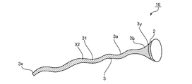
- FIG. 1 is a schematic view of a medical instrument 10 according to one embodiment of the present invention.
- the medical instrument 10 includes at least one attachment portion 2 and at least one tubular portion 3.
- the medical instrument 10 includes one attachment portion 2 and one cylindrical portion 3.
- At least one end of the cylindrical portion 3 is open.
- the both ends (namely, the edge part 3x on the opposite side to the attachment part 2, and the edge part 3y on the attachment part 2 side) of the cylindrical part 3 are opening.
- the mounting portion 2 is provided on at least a part of the cylindrical portion 3.
- the attachment portion 2 can be provided at any appropriate position of the tubular portion 3. In the illustrated example, the attachment portion 2 is provided at the end portion 3 y of the cylindrical portion 3.
- the mounting portion 2 and the cylindrical portion 3 may be integrated or may be a separate member combined.
- the attachment portion 2 and the cylindrical portion 3 are integral. That is, a predetermined region at the end of the cylindrical portion 3 is the attachment portion 2.
- the attachment portion 2 typically has any suitable configuration that allows the medical instrument 10 to be attached to the digestive tract cavity via the attachment portion 2.
- the attachment portion 2 may be attachable to the digestive tract cavity via another member, or may be directly attachable to the digestive tract cavity (including a mechanism that can be attached by internal use).
- Examples of the configuration that allows the attachment portion 2 to be directly attached to the digestive tract cavity include a stent.
- the attachment portion 2 preferably has any suitable configuration that can be attached to the digestive tract cavity via another member.
- a medical instrument can be arrange
- the another member include a thread (for example, a suture thread), a stapler, a hook, a clip, and a combination thereof.
- the cylindrical portion 3 is configured to be arranged along at least a part of the digestive tract. Any appropriate configuration may be adopted as the above configuration.
- the cylindrical portion 3 can typically be bent in the longitudinal direction.
- At least a part of the side surface of the cylindrical portion 3 is configured to be able to follow the shape of the inner wall of the digestive tract.
- being able to follow the shape of the inner wall of the gastrointestinal tract means that it can be in close contact with the inner wall of the gastrointestinal tract according to gastrointestinal motility when the medical instrument is used.
- Arbitrary appropriate length can be employ
- FIG. The length is, for example, 30 cm to 9 m.
- the medical instrument can be easily disposed in the digestive tract cavity without impairing the digestion and absorption suppressing effect of the medical instrument.
- the shape, area, and length of each member mean the shape, area, and length of the medical device in the initial state unless otherwise specified.
- the cylindrical portion 3 may be stretchable in the longitudinal direction when the medical instrument 10 is used, or may not be stretchable. Preferably, the cylindrical part 3 cannot extend in the longitudinal direction. Since the cylindrical part 3 cannot extend in the longitudinal direction, the position of the end 3x of the cylindrical part 3 is stabilized when the medical instrument 10 is used.
- being unextendable means, for example, that the length at the maximum extension is 110% or less with respect to the length before extension.
- At least a part of the cylindrical portion 3 is typically deformable in accordance with gastrointestinal motility.
- At least a part of the cylindrical part 3 can typically be expanded in the diameter direction of the cylindrical part 3 in accordance with the digestive tract movement.
- Any appropriate ratio can be adopted as the ratio of the cross-sectional area at the time of maximum expansion of the cross-section to the cross-sectional area of at least a part of the cross-section of the cylindrical portion 3.
- it is 200% or more, for example.
- At least a part of the cylindrical part 3 can typically be reduced in the diameter direction of the cylindrical part 3 according to the digestive tract movement.
- Any appropriate ratio can be adopted as the ratio of the cross-sectional area at the time of maximum reduction of the cross-section to the cross-sectional area of at least a part of the cross-section of the cylindrical portion 3.
- it is 75% or less, for example.
- the shape of the cross section of the cylindrical part 3 can take any appropriate shape. As said shape, a substantially circular shape is mentioned, for example.
- the tubular portion 3 has a constant region 3a where the cross-sectional area of the cross section of the tubular portion 3 is substantially constant, and an increasing region 3b where the cross-sectional area of the cross section of the tubular portion 3 increases.
- the constant region 3a extends in a direction from the end 3x toward the end 3y.
- the increasing region 3b extends from the end of the constant region 3a on the end 3y side to the end 3y.
- the cross-sectional area of the cross section of the cylindrical portion 3 increases in a tapered shape toward the end portion 3y.
- the length of the fixed region 3a is, for example, 60% or more, preferably 80% or more, with respect to the entire length of the cylindrical portion 3.
- Arbitrary appropriate cross-sectional areas can be employ
- the cross-sectional area is, for example, 2 cm 2 to 12 cm 2 .
- the cylindrical portion 3 is typically configured to transmit a part of the digested liquid and / or digested contents.
- the cylindrical part 3 can take any appropriate shape. At least a part of the cylindrical portion 3 is, for example, a net shape (FIGS. 1 and 2), a strip shape (FIG. 3), a slit shape (FIG. 4), a perforated shape (FIG. 5), and an uneven shape (FIG. 6). , Membranes (FIG. 7), and combinations thereof. Preferably, at least a part of the cylindrical portion 3 has a net shape, a strip shape, a slit shape, a perforated shape, and a combination thereof. More preferably, at least a part of the cylindrical portion 3 has a net shape. In this specification, the form of FIG. 1 (form in which the entire cylindrical portion 3 is net-shaped) will be mainly described, and only other characteristic parts of the other forms will be briefly described later.
- the cylindrical portion 3 When at least a part of the cylindrical portion 3 is a net shape, a strip shape, a slit shape, a perforated shape, or a combination thereof, the cylindrical portion is easily deformed, and the shape followability to the inner wall of the digestive tract is improved. To do. As a result, suppression of gastrointestinal motility is more effectively prevented, and physical stimulation to the inner wall of the gastrointestinal tract is further increased. Therefore, the effect of preventing atrophy of the digestive tract mucosa is improved. Furthermore, since a part of digested liquid and / or digested contents can be easily permeated through the tubular portion, damping syndrome can be effectively prevented.
- the period during which the medical device exhibits the digestion absorption suppressing effect can be easily adjusted.
- the above adjustment is performed by using a biodegradable material as a material constituting the cylindrical part and adjusting, for example, the area and / or the aperture ratio of the net, strip, and / or slit constituting the cylindrical part. Is called.
- the cylindrical portion 3 is net-shaped, the cylindrical portion is difficult to twist in the digestive tract, so that the occurrence of gastrointestinal obstruction can be easily prevented. Further, the cylindrical portion can be easily made unextendable in the longitudinal direction.
- Examples of the net shape include a mesh shape, a lattice shape, a chain insulator shape, and combinations thereof.
- the shape is a mesh. Any appropriate shape can be adopted as the chain-like shape. Examples of the chain-like shape include 4to1, 6to1, and / or 4to2.
- the opening 32 of the net 31 can take any suitable shape.
- the opening 32 has a substantially rhombus shape.
- the opening 32 can have a substantially polygonal shape and a substantially circular shape.
- Examples of the substantially polygonal shape include a substantially rectangular shape.
- Examples of the substantially rectangular shape include a substantially rectangular shape (including a square shape) and a substantially rhombus shape.
- As the substantially quadrangle constituting the substantially quadrilateral shape a substantially quadrangle in which one of the two diagonal lines is substantially parallel to the longitudinal direction of the cylindrical portion 3 is preferable.
- the cylindrical portion can be easily made unextendable in the longitudinal direction.
- the aperture ratio of the net 31 any appropriate aperture ratio can be adopted according to the target diet effect, the area ratio of the net-like portion, and the like.
- the opening ratio of the net 31 is, for example, 1% to 99.9%, preferably 40% to 99%. More preferably, it is 60% to 95%.
- the opening ratio is within the above range, atrophy of the digestive tract mucosa can be effectively prevented.
- the permeability of the cylindrical portion is increased, damping syndrome can be effectively prevented. Furthermore, a sufficient digestion absorption suppression effect by the medical device can be obtained.
- the opening size of the net 31 can be in the order of microns to millimeters depending on the purpose. That is, the net 31 may be a literal net or may be a porous film substantially.
- the mounting part 2 can take any appropriate shape.
- the attachment portion 2 is configured integrally with the tubular portion 3, and thus can have the same shape as the tubular portion 3. Therefore, the attachment part 2 is, for example, a net shape (FIG. 1), a strip shape, a slit shape, a perforated shape, an uneven shape, a membrane shape, and a combination thereof.
- the attachment portion 2 includes a net shape, a strip shape, a slit shape, a perforated shape, and a combination thereof. More preferably, the attachment portion 2 includes a net shape.
- the attachment part 2 is integral with the net-like cylindrical part 3, and the whole attachment part 2 is net-like.
- the medical instrument can be more easily arranged and extracted. As a result, it becomes easy to return to the preoperative state at an appropriate time.
- the attachment part 2 has shown the form which is net shape.
- 2 to 7 show a form in which the attachment portion 2 is in the form of a membrane.
- Arrangement material of medical instrument Arbitrary appropriate material can be adopted as a material which constitutes medical instrument 10. Examples of the material include biodegradable materials and non-biodegradable materials.
- biodegradable material can be adopted as the biodegradable material.
- biodegradable material include biodegradable synthetic polymers, biological biodegradable materials, and combinations thereof.
- biodegradable synthetic polymer can be adopted as the biodegradable synthetic polymer.
- the biodegradable synthetic polymer include glycolide polymers, dioxanone polymers, lactide polymers, and combinations thereof.
- the biodegradable synthetic polymer is a glycolide polymer, glycolide-lactide copolymer, glycolide-trimethylene carbonate copolymer, glycolide-dioxanone-trimethylene carbonate copolymer, glycolide-epsilon caprolactone copolymer.
- the biodegradable synthetic polymer is a glycolide polymer, glycolide-lactide copolymer, glycolide-trimethylene carbonate copolymer, dioxanone polymer, or a combination thereof.
- Any appropriate biological biodegradable material can be adopted as the biological biodegradable material.
- an animal origin biodegradable material is mentioned, for example.
- the animal-derived biodegradable material is fibroin (eg, silk constituent), animal serosa (eg, cut gut constituent), spidroin (eg, spider silk constituent), and combinations thereof It is.
- the entire medical instrument 10 may be made of a biodegradable material.
- any appropriate non-biodegradable material can be adopted as the non-biodegradable material.
- the non-biodegradable material include synthetic polymers, biological materials, metals, and combinations thereof.
- Any appropriate synthetic polymer can be adopted as the synthetic polymer.
- the synthetic polymer include olefin polymers (for example, polyvinyl chloride, polyethylene, and polypropylene), urethane polymers (for example, polyurethane), silicone, amide polymers (for example, nylon (registered trademark)). ), Ester polymers, and combinations thereof.
- Any appropriate biological material can be adopted as the biological material.
- Any appropriate metal can be adopted as the metal.
- an iron containing metal for example, stainless steel is mentioned, for example.
- the material constituting the medical instrument 10 is typically a synthetic polymer, a metal, or a combination thereof. By having the said structure, the possibility of the infection at the time of medical instrument use can be excluded more reliably.
- the medical instrument 10 may contain a radiopaque material.
- the medical instrument containing an X-ray non-transparent substance include, for example, a medical instrument to which a member containing an X-ray non-transparent substance is attached, a medical instrument composed of a material containing an X-ray impermeable substance, Examples thereof include a medical device coated with a material containing a radiopaque material and a medical device containing a radiopaque material. Any appropriate substance can be adopted as the X-ray impermeable substance.
- the radiopaque material include barium sulfate, any appropriate metal material having radiopacity, and any radiopaque marker used in medical instruments (eg, catheters and stents). Suitable materials.
- the X-ray non-transparent metal material examples include platinum, palladium, platinum-iridium alloy, and platinum-nickel alloy.
- a member containing the said X-ray non-permeable substance a wire and a contrast thread are mentioned, for example.
- the member is typically made of a fiber containing the X-ray impermeable substance (for example, barium sulfate).
- At least a part of the medical instrument 10 may be coated with any appropriate material.
- the material containing an antimicrobial material for example, fluorine
- an antimicrobial material for example, fluorine
- Specific products include “Cytop” (manufactured by Asahi Glass Co., Ltd.), “Novec EGC-1720” and “Novec EGC-1700” (manufactured by 3M), “Defensor TR” (manufactured by Dainippon Ink Chemical Co., Ltd.), and These combinations are mentioned. Any appropriate method can be adopted as a method of coating the medical device 10.
- Examples of the method include a method in which the medical device 10 is dipped on the coating material and then dried, and a method in which the coating material is sprayed onto the medical device 10.
- a method in which the medical device 10 is dipped on the coating material and then dried and a method in which the coating material is sprayed onto the medical device 10.
- the constituent material of the cylindrical part 3 As a material which comprises the cylindrical part 3, arbitrary appropriate materials can be employ
- the material which comprises the medical instrument 10 mentioned above is mentioned, for example.
- the material constituting the cylindrical portion 3 may include an elastic material.
- the material having elasticity include an elastomer.
- the elastomer include rubber, thermoplastic elastomer, and combinations thereof.
- At least a part of the cylindrical part 3 may be composed of a nonwoven fabric.
- Arbitrary appropriate fiber can be employ
- the fiber include fibers derived from olefin polymers (for example, polypropylene fibers and polyethylene fibers), fibers derived from ester polymers (for example, polyester fibers), and combinations thereof. Since at least a part of the cylindrical portion 3 is made of a nonwoven fabric, the permeability of the nonwoven fabric portion is reduced, so that the corresponding digestive tract cavity can be effectively protected.
- At least a part of the cylindrical portion 3 is composed of fibers. Any appropriate fiber can be adopted as the fiber.
- the fiber which consists of the material which comprises the medical instrument 10 is mentioned, for example.
- the fiber may be a biodegradable fiber or a non-biodegradable fiber. Since at least a part of the cylindrical part 3 is made of fiber, at least a part of the cylindrical part can be easily formed into a net shape. Further, since the fiber is a biodegradable fiber (for example, a suture thread), after the medical device is placed in the digestive tract, the cylindrical portion is gradually decomposed and excreted together with the feces, so that it was placed. It is possible to treat obesity without performing an operation for collecting the tubular portion from the digestive tract.
- biodegradable fiber any appropriate biodegradable fiber can be adopted as the biodegradable fiber.
- the fiber which consists of a biodegradable material which comprises the medical instrument 10 is mentioned, for example.
- the biodegradable fiber PDSII (registered trademark), maxon, dexon (registered trademark), bicyclyl (registered trademark), silk thread, spider silk, cut good, bicyclyl rapid (registered trademark), monoacryl ( Registered trademark), and combinations thereof.
- the biodegradable fiber is PDSII (registered trademark), maxon, dexon (registered trademark), bicyclyl (registered trademark), and combinations thereof.
- non-biodegradable fiber any appropriate non-biodegradable fiber can be adopted as the non-biodegradable fiber.
- the non-biodegradable fiber the fiber which consists of a non-biodegradable material which comprises the medical instrument 10 is mentioned, for example.
- the non-biodegradable fibers include polyamide fibers, polyolefin fibers, metal fibers, and combinations thereof.
- the polyamide fiber include nylon (registered trademark).
- polyolefin fiber a polypropylene fiber is mentioned, for example.
- metal fibers include stainless steel fibers.
- the fiber may include a stretched fiber. Since the said fiber becomes difficult to expand
- the average diameter D of the fibers is, for example, 100 ⁇ m to 1 mm.
- the medical device maintains the shape and controls the period during which the digestion absorption suppression effect is exhibited. Becomes easier.
- the control method is performed, for example, by selecting an appropriate biodegradable fiber in consideration of durability in the digestive tract cavity.
- the net 31 can be constituted by the fibers.
- the net 31 can be obtained by any suitable method.
- the method for forming the net 31 include a forming step, a knitting step (for example, a knit knitting step), a weaving step, an adhering step, an intertwining step, or a combination of these steps.
- the method preferably includes a forming step, a knitting step, or a weaving step.
- molding is mentioned as said shaping
- the molding is extrusion molding.
- the direction in which the cylindrical portion extends can be easily adjusted.
- the adhering step and the intertwining step can be performed by any appropriate treatment.
- the treatment include physical treatment (for example, heat treatment and mechanical treatment), and chemical treatment.
- attachment part As a material which constitutes attachment part 2, arbitrary appropriate materials can be adopted. As said material, the material which comprises the medical instrument 10 mentioned above is mentioned, for example.
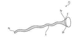
- FIG. 2 is a schematic view of a medical instrument 11 according to another embodiment of the present invention.
- the attachment portion 2 and the cylindrical portion 3 are separate members combined.
- the attachment portion 2 and the tubular portion 3 are joined at a boundary 20 between the attachment portion 2 and the end portion 3y of the tubular portion 3.
- Any appropriate means can be adopted as the coupling means.
- the coupling means include a thread (for example, a suture), a stapler, an adhesive, a hook, and a combination thereof.
- FIG. 3 is a schematic view of a medical instrument 12 according to still another embodiment of the present invention.
- the shape of the cylindrical part 3 is strip shape. Any appropriate strip can be adopted as the strip 33 defined by the strip shape.
- any ratio can be adopted as the ratio of the length of the strip 33 to the entire length of the tubular portion 3.
- the ratio is, for example, 80% to 100%.
- a strip 33 extends from the end 3x of the cylindrical portion 3 to the end 3y.
- FIG. 4 is a schematic view of a medical instrument 13 according to still another embodiment of the present invention.
- the cylindrical part 3 is slit shape.
- any appropriate slit can be adopted as the slit 34 defined by the slit shape.
- any appropriate direction can be adopted as the direction of the slit 34.
- the longitudinal direction of the slit 34 is substantially parallel to the longitudinal direction of the cylindrical portion 3.
- the aperture ratio of the slit 34 is, for example, 40% to 70%.
- the opening ratio is within the above range, it is possible to obtain a sufficient digestion absorption suppression effect by a medical instrument while effectively preventing atrophy of the digestive tract mucosa and a dumping syndrome.
- FIG. 5 is a schematic view of a medical instrument 14 according to yet another embodiment of the present invention.
- the cylindrical part 3 is perforated.
- the hole 35 can take any suitable shape. Examples of the shape include a substantially polygonal shape, a substantially elliptical shape (for example, a substantially circular shape), and combinations thereof. In the illustrated example, the hole 35 is substantially circular.
- the aperture ratio of the hole 35 any appropriate aperture ratio can be adopted.
- the opening ratio of the hole 35 is, for example, 40% to 70%. When the opening ratio is within the above range, it is possible to obtain a sufficient digestion absorption suppression effect by a medical instrument while effectively preventing atrophy of the digestive tract mucosa and a dumping syndrome.
- FIG. 6 is a schematic view of a medical instrument 15 according to still another embodiment of the present invention.
- the cylindrical part 3 is uneven
- convex part 36 which forms the above-mentioned uneven shape.
- Any appropriate height can be adopted as the height of the convex portion 36.
- the height of the convex portion 36 is, for example, 1 mm to 5 cm. When the height of the convex part 36 is a certain value or more, the effect of preventing the atrophy of the digestive tract mucosa and the digestive tract obstruction is further improved.
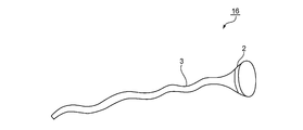
- FIG. 7 is a schematic view of a medical instrument 16 according to still another embodiment of the present invention.
- the cylindrical portion 3 has a membrane shape.
- any suitable membrane can be adopted as the membrane forming the membrane shape.
- Any appropriate material can be adopted as the material constituting the membrane.
- the material which comprises the said membrane the material which comprises the above-mentioned medical instrument 10 is mentioned, for example.
- the material is a metal.
- Specific examples of the membrane include metal foil.
- the mounting portion 2 and the cylindrical portion 3 are separate members, but it goes without saying that they may be integrated. Furthermore, the above-described embodiments may be appropriately combined, and the above-described embodiments may be combined with a configuration well known in the industry.
- Medical devices can be used for any suitable application in addition to treating obesity. Examples of the use include drug administration, gastrointestinal protection, and combinations thereof.
- Examples of medical devices used for drug administration include medical devices containing drugs.
- Examples of the medical device containing a drug include a medical device made of a material mixed with a drug and a medical device coated with the drug.
- the drug is preferably a drug that exhibits a function in the digestive tract. More specifically, therapeutic agents for renal failure (for example, activated carbon (for example, cremedin)), therapeutic agents for hyperkalemia (for example, ion-exchange resin (for example, sodium polystyrene sulfonate)), therapeutic agents for hypercholesterolemia (for example, an anion exchange resin (for example, colestimide), an ulcerative colitis therapeutic agent, a gastric ulcer therapeutic agent, a mucosal protective agent (for example, Marsulenes, Monirak, and combinations thereof), a diet effect promoter (for example, mucin, Fiber, bifidobacteria, bolus solidifying agent, and combinations thereof), and combinations thereof. By using a diet effect promoter as the drug, the diet effect can be promoted.
- a diet effect promoter for example, mucin, Fiber, bifidobacteria, bolus solidifying agent, and combinations thereof
- Examples of the medical instrument used for protection in the digestive tract cavity include a medical instrument in which the permeability of at least a part of the cylindrical portion 3 is reduced. At least a part of the portion where the permeability of the cylindrical portion 3 is reduced may be made of a nonwoven fabric. Examples of the position of the portion where the permeability of the cylindrical portion 3 is reduced include a position corresponding to a site requiring protection in the digestive tract cavity. Examples of the site requiring protection include a lesion in the digestive tract cavity (for example, a cancerous and / or ulcerous site of the digestive tract). By having the said structure, the inside of a digestive tract cavity can be protected effectively.
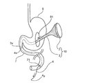
- FIG. 8 is a schematic diagram illustrating an example of a state in which the medical device 10 according to one embodiment of the present invention is disposed in the digestive tract cavity.
- the medical instrument 10 is disposed in the digestive tract cavity by attaching the attachment portion 2 to at least a part of the inner wall of the digestive tract.
- the medical device 10 is disposed along the intestinal tract 7 from the stomach 6 by attaching the attachment portion 2 in the stomach 6.
- the intestinal tract includes a duodenal tract.
- the attachment portion 2 is attached along the entire circumference of the inner wall of the digestive tract. In the illustrated example, the attachment portion 2 is attached over the entire inner wall of the stomach 6.
- the attachment portion 2 is attached along the inner wall of the digestive tract by the attachment means 30.
- Any appropriate means can be adopted as the attaching means 30.
- the attachment means 30 include a thread (for example, a suture thread), a stapler, a clip, and a combination thereof.
- any appropriate digestive tract can be adopted as the digestive tract to which the attachment portion 2 is attached.
- the digestive tract include the esophagus, stomach, and intestinal tract.
- the gastrointestinal tract is preferably the stomach (for example, the pylorus of the stomach, the cardia of the stomach, or the vicinity thereof).
- the attachment portion 2 is attached to the pyloric portion of the stomach 6.
- the cylindrical part 3 is arranged downstream of the digestive tract of the attachment part 2.
- the tubular portion 3 is disposed along at least a part of the stomach 6 and the intestinal tract 7 or at least a part of the intestinal tract 7.
- the cylindrical part 3 is arrange
- any appropriate ratio can be adopted.
- the ratio is, for example, 30% to 80%.
- the fixed region 3a of the cylindrical portion 3 can be arranged at any appropriate position.
- the constant region 3 a is disposed along the intestinal tract 7.
- the increased area 3b of the cylindrical portion 3 can be arranged at any appropriate position.
- the increase region 3 b is disposed along the pyloric part of the stomach 6.
- the increased region 3b By disposing the increased region 3b along a specific gastrointestinal tract (for example, the stomach 6), the expanded state of the gastrointestinal tract can be adjusted when the medical instrument is used.
- the influence on exercise can be easily controlled.
- the effect of inhibiting digestion and absorption can be easily adjusted by controlling the absorption of food and the absorption rate in the digestive tract (eg, intestinal tract 7) located downstream of the digestive tract.
- FIGS. 9-11 are schematic diagrams illustrating an example of a method for placing medical device 10 in the gastrointestinal lumen according to one embodiment of the present invention.
- a perforation operation is performed on the intestinal tract 7 with respect to the laparotomized subject to form an intestinal perforation portion 71.
- the position where the intestinal perforation part 71 is formed is a position where the end part 3x of the tubular part 3 is to be disposed.
- an incision operation is performed on the front surface of the stomach 6 to form a gastric incision 61.
- the blunt threading needle 4 is inserted into the intestinal perforation part 71, and the blunt threading needle 4 is inserted in the direction from the intestinal perforation part 71 toward the gastric incision part 61 (that is, retrograde) as shown by an arrow in FIG. send.
- one end 4x of the blunt threading needle 4 passes through the gastric incision 61 (FIG. 9).
- the other end 4y of the blunt threading needle 4 is located outside the intestinal perforation 71 (FIG. 9).
- the medical instrument 10 and the blunt threading needle 4 is sent in a direction (ie, antegrade) from the gastric incision 61 toward the intestinal perforation 71 as indicated by an arrow in FIG.
- the end 3x of the tubular portion 3 reaches the intestinal perforation portion 71, and the attachment portion 2 reaches the pyloric portion of the stomach 6 (not shown).
- the tubular portion 3 and the blunt threading needle 4 are separated from each other, so that the end portion 3x of the tubular portion 3 is disposed at a position where the intestinal perforation portion 71 is formed in the intestinal tract 7 (FIG. 11).
- the attachment part 2 is fixed with a thread and / or a stapler along the entire inner wall of the pyloric part of the stomach 6 (that is, in the entire periphery) (FIG. 11).
- the stomach incision 61 and the intestinal perforation 71 are sewn and closed.
- FIG. 12 is a schematic diagram for explaining an example of a method for placing the medical device 10 in the digestive tract cavity according to one embodiment of the present invention.
- the endoscope 9 includes an operation unit 91, a tube unit 92, and a foreign object forceps unit 93 in this order.
- the endoscope 9 is inserted into the tubular portion 3 of the medical instrument 10 with the foreign forceps portion 93 in advance, and the end portion 3x of the tubular portion 3 is held by the foreign forceps portion 93 (not shown).
- the medical instrument 10 and the endoscope 9 are inserted from the oral cavity 8 with the end 3x of the medical instrument 10 and the foreign object forceps 93 positioned in advance (FIG. 12).
- the stomach 6 is passed through the end portion 3x and the foreign body forceps portion 93, and further inserted into the intestinal tract 7, so that the attachment portion 2 reaches the pyloric portion of the stomach 6 (FIG. 12).
- the holding of the end 3x by the foreign forceps 93 is released, and only the endoscope 9 is pulled out to the stomach 6 (not shown).
- the attachment portion 2 is fixed using a hemostatic clip at a minimum of eight locations along the entire inner wall of the pyloric portion of the stomach 6.
- the medical device 10 is placed in the digestive tract cavity of an animal, and the change in body weight is measured to test the effect of suppressing the absorption and digestive tract mucosal atrophy of the medical device. did.
- a gastro-jejunal lumen membrane conical (Gastro Jejunal Inner Lumen membrane Windsock shaped) medical device having both ends opened was used as the medical device 10.
- the medical instrument is referred to as a GJIMW instrument.
- the specific test method is as follows.
- tracheal intubation was performed, and controlled breathing was performed by a veterinarian specialized in anesthesia. Changed from controlled breathing to spontaneous breathing as needed. Anesthesia was maintained until the end of surgery so that the end-expiratory concentration of isoflurane (trade name “Isoflu”, manufactured by DS Pharma Animal Health) was 0.8-1.6%.
- isoflurane trade name “Isoflu”, manufactured by DS Pharma Animal Health
- 20 mg / kg of cefazolin (trade name “cefamedin”, manufactured by Astellas Pharma Inc.) was intravenously administered twice a day before surgery and for 5 days after surgery.
- the animals were operated on by the method described in Section D with reference to FIGS. 9 to 11, and a GJIMW device was placed in the digestive tract cavity of the animals.
- an introduction catheter (trade name “New Enteral feeding tube”, manufactured by Covidien) was used as a blunt thread landing needle.
- a biodegradable suture was used to sew one end of the GJIMW device to the entire inner wall of the small intestine and fix it.
- the other end (end of jejunum side) of the GJIMW device was also fixed using two biodegradable sutures.
- the gastric incision and intestinal perforation were sewn and closed, and then washed with physiological saline. From 15 hours after the operation, the animals were allowed unlimited access to food (manufactured by Nippon Nosan Kogyo Co., Ltd.) and water.
- Example 1 As a medical instrument, a non-woven GJIMW instrument (Nonwoven, 125 cm, polypropylene, manufactured by Dio Kasei Co., Ltd.) was used. The width on the small intestine side of the GJIMW device is 2 cm. The GJIMW device is shown as (a) in the upper part of the photograph in FIG. The scale bar shown in FIG. 13 has a length of 10 cm. Animals were weighed every week after surgery. The results are shown in the graph of FIG. In addition, blood tests were performed before surgery and 5 weeks after surgery. The results are shown in Table 1.
- Example 2 The same experiment as in Example 1 was performed except that a net-like GJIMW device (Short fabric net, 45 cm, polyethylene, manufactured by Morishita Co., Ltd.) was used.
- a net-like GJIMW device Short fabric net, 45 cm, polyethylene, manufactured by Morishita Co., Ltd.
- Example 3 The same experiment as in Example 1 was performed except that a net-like GJIMW device (Long fabric net, 115 cm, polyethylene, manufactured by Morishita Co., Ltd.) was used.
- the GJIMW device is shown as (b) in the middle of the photograph in FIG.
- Example 4 The same experiment as in Example 1 was performed except that stockings (Short nylon stocking, 35 cm, nylon, manufactured by Atsugi Co., Ltd.) were used as a GJIMW instrument.
- Example 5 The same experiment as in Example 1 was performed except that stockings (Long nylon stocking, 109 cm, nylon, manufactured by Atsugi Co., Ltd.) were used as a GJIMW instrument.
- the GJIMW instrument is shown as (c) in the lower part of the photograph in FIG.
- Example 1 The same experiment as in Example 1 was performed except that no surgery was performed and the GJIMW device was not placed in the digestive tract cavity of an animal (Control).
- Example 2 A gastric incision and intestinal perforation were performed, but the same experiment as in Example 1 was performed except that the GJIMW device was closed without being placed in the digestive tract cavity of the animal (Sham-operated).
- Table 1 shows that the animals used in Examples 1 to 5 and Comparative Examples 1 and 2 were subjected to blood tests before surgery (Pre-operation) and 5 weeks after surgery (5 weeks). ), Albumin concentration (Alb), total cholesterol concentration (Total cholesterol), triacylglycerol concentration (TG), HDL cholesterol concentration (HDL), and LDL cholesterol concentration (LDL). As shown in Table 1, there was no significant difference in blood test results between the animals used in Examples 1 to 5 and the animals used in Comparative Examples 1 and 2. Therefore, it was considered that there was no general health status difference between these animals.
- FIG. 14 is a graph showing the results of weight measurement in Examples 1 to 5 and Comparative Examples 1 and 2.
- the vertical axis of the graph shows the ratio of the measured body weight when the weight on the day of surgery is 100%.
- the horizontal axis of the graph indicates the time elapsed since the operation in units of weeks.
- Example 1 Nonwoven
- Example 3 Long fabric net
- an increase in body weight was suppressed as compared with Comparative Examples 1 and 2.
- the weights on the day of surgery were 7.0 kg and 7.6 kg, respectively, and the weights after 5 weeks after the surgery were 19.2 kg and 20.2 kg, respectively, Body weight increased nearly 3 times.
- the body weights of the animals in Examples 1 and 3 were 8.0 kg and 7.4 kg respectively on the day of surgery, and 11.6 kg and 13.36 kg after 5 weeks from the surgery, respectively, for 5 weeks after the surgery.
- the body weight gain was about 1.7 times (about 60% of the body weight of the animals in Comparative Examples 1 and 2). Therefore, it was shown that digestion and absorption are suppressed by these GJIMW devices.
- Example 5 Long nylon stocking
- the body weight decreased from 1 to 3 weeks after the operation, but the GJIMW device was excreted 3 weeks later (time indicated by the downward arrow in FIG. 14).
- the body weight of the animal in Example 5 increased to the same extent as that of the animal in Comparative Example 2 from 3 to 5 weeks after the operation. Specifically, in Comparative Example 2, the body weight was about 1.4 times 3 to 5 weeks after the operation, and in Example 5, the body weight was about 1.5 times during the same period. In other words, it was found that even in animals using GJIMW devices, digestion and absorption can be performed to a normal level if the GJIMW device is removed. If the digestive tract mucosa is atrophied by using the GJIMW device, the digestion and absorption efficiency is lowered, so that it is considered that the same weight gain as in Comparative Example 2 does not occur.
- Example 2 Short fabric net
- Example 4 Short nylon stocking
- the GJIMW device did not function normally, and an increase in body weight comparable to Comparative Examples 1 and 2 was observed.
- the GJIMW device was refluxed from the duodenum to the stomach, and in Example 4, the GJIMW device was discharged from the stomach vestibule and excreted. Both the backflow and the outflow were observed within one week from the operation (time indicated by the upward arrow in FIG. 14).
- Example 6 For the animals sacrificed in Example 1, pathological specimens of stomach and intestines were prepared according to a conventional method.
- parts which produced the pathological specimen are the stomach non-coating part A, the gastric coating part B, the intestinal tract coating part C, and the intestinal tract non-coating part D which are shown below.
- the pathological specimen was observed using a microscope (manufactured by Olympus, model number “BX51”), and a photograph with a magnification of 40 times was obtained.
- FIGS. 16A to 16D show photographs showing the observation results of the pathological specimens of the stomach uncovered portion A, the stomach covered portion B, the intestinal tract covered portion C, and the intestinal tract uncovered portion D, respectively.
- FIGS. 16 (A) and 16 (B) there is no difference in the histological findings of the stomach non-covering portion A and the stomach covering portion B, and only slight fibrosis is observed at any site. No atrophy was observed.
- FIGS. 16C and 16D there is no difference in the histological findings of the intestinal tract covering portion C and the intestinal tract non-covering portion D, and only slight fibrosis is observed in any portion. Mucosal atrophy was not observed. Therefore, it was shown that if the GJIMW device of Example 1 was used, no atrophy of the gastrointestinal mucosa occurred.
- Example 7 The same experiment as in Example 6 was performed, except that a pathological specimen was prepared for the animal killed in Example 3. 17A, 17B, 17C, and 17D show photographs showing the observation results of pathological specimens of the stomach uncovered portion A, stomach covered portion B, intestinal tract covered portion C, and intestinal tract uncovered portion D, respectively. ).
- FIG. 17 (A) no atrophy of the gastric mucosa was observed in the stomach non-covered portion A.
- FIG. 17B only partial wrinkles, partial mucosal thinning, and slight inflammation were observed in the gastric covering portion B, and no gastric mucosal atrophy was observed. It was.
- FIGS. 17 (C) and (D) there is no difference in the histological findings of the intestinal tract covering portion C and the intestinal tract non-covering portion D. Only a slight degree of inflammation and slight inflammation was observed, and no intestinal mucosal atrophy was observed. Therefore, it was shown that when the GJIMW device of Example 3 was used, atrophy of the gastrointestinal mucosa did not occur.
- Example 8 An experiment similar to that in Example 6 was performed, except that a pathological specimen was prepared for the animal sacrificed in Example 5.
- 18A, 18B, 18C, and 18D show photographs showing the observation results of pathological specimens of the stomach uncovered portion A, the stomach covered portion B, the intestinal tract covered portion C, and the intestinal tract uncovered portion D, respectively. ).
- FIGS. 18 (A) and (B) there is no difference in the histological findings of the stomach non-covering part A and the stomach covering part B, and only slight fibrosis is observed in any part. No atrophy was observed.
- FIGS. 18C and 18D there is no difference in the histological findings of the intestinal tract covering portion C and the intestinal tract non-covering portion D, and partial wrinkles and partial mucosal thinning are observed in any part. Only a slight degree of inflammation and slight inflammation was observed, and no intestinal mucosal atrophy was observed. Therefore, it was shown that when the GJIMW device of Example 5 was used, no atrophy of the gastrointestinal mucosa occurred.
Abstract
Priority Applications (4)
| Application Number | Priority Date | Filing Date | Title |
|---|---|---|---|
| JP2015534705A JP5902869B2 (ja) | 2014-03-28 | 2015-03-12 | 医療用器具 |
| US15/129,671 US10292853B2 (en) | 2014-03-28 | 2015-03-12 | Medical instrument |
| EP15769822.6A EP3123945B1 (fr) | 2014-03-28 | 2015-03-12 | Instrument médical |
| CN201580017130.9A CN106456143B (zh) | 2014-03-28 | 2015-03-12 | 医疗用器具 |
Applications Claiming Priority (2)
| Application Number | Priority Date | Filing Date | Title |
|---|---|---|---|
| JP2014068503 | 2014-03-28 | ||
| JP2014-068503 | 2014-03-28 |
Publications (1)
| Publication Number | Publication Date |
|---|---|
| WO2015146612A1 true WO2015146612A1 (fr) | 2015-10-01 |
Family
ID=54195135
Family Applications (1)
| Application Number | Title | Priority Date | Filing Date |
|---|---|---|---|
| PCT/JP2015/057361 WO2015146612A1 (fr) | 2014-03-28 | 2015-03-12 | Instrument médical |
Country Status (5)
| Country | Link |
|---|---|
| US (1) | US10292853B2 (fr) |
| EP (1) | EP3123945B1 (fr) |
| JP (1) | JP5902869B2 (fr) |
| CN (1) | CN106456143B (fr) |
| WO (1) | WO2015146612A1 (fr) |
Cited By (3)
| Publication number | Priority date | Publication date | Assignee | Title |
|---|---|---|---|---|
| WO2020080379A1 (fr) * | 2018-10-19 | 2020-04-23 | 社会医療法人蘇西厚生会まつなみリサーチパーク | Outil médical |
| JP2020521606A (ja) * | 2017-06-27 | 2020-07-27 | 杭州糖吉医▲療▼科技有限公司Hangzhou Tangji Medical Technology Co., Ltd. | 胃フローダイバーター、及びその消化管抗菌カテーテル |
| WO2020162359A1 (fr) * | 2019-02-04 | 2020-08-13 | 川澄化学工業株式会社 | Dispositif tubulaire à demeure |
Families Citing this family (7)
| Publication number | Priority date | Publication date | Assignee | Title |
|---|---|---|---|---|
| BR102015011376B1 (pt) | 2015-05-18 | 2023-04-04 | Murilo Pundek Rocha | Brônquio artificial implantável |
| FR3063007A1 (fr) * | 2017-02-17 | 2018-08-24 | Jean Michel Verd | Dispositif implantable de traitement des desordres metaboliques |
| CN107158546B (zh) * | 2017-06-27 | 2018-11-30 | 杭州糖吉医疗科技有限公司 | 胃导流器 |
| US20210184210A1 (en) * | 2018-04-16 | 2021-06-17 | The Regents Of The University Of California | Anode material for rechargeable li-ion batteries |
| USD902407S1 (en) * | 2019-11-19 | 2020-11-17 | Pulmair Medical, Inc. | Implantable artificial bronchus |
| USD954953S1 (en) | 2020-11-03 | 2022-06-14 | Pulmair Medical, Inc. | Implantable artificial bronchus |
| USD1014758S1 (en) | 2023-04-19 | 2024-02-13 | Pulmair Medical, Inc. | Implantable artificial bronchus |
Citations (4)
| Publication number | Priority date | Publication date | Assignee | Title |
|---|---|---|---|---|
| US6740121B2 (en) * | 2001-11-09 | 2004-05-25 | Boston Scientific Corporation | Intragastric stent for duodenum bypass |
| JP2005500127A (ja) * | 2001-08-27 | 2005-01-06 | シネコー・エルエルシー | 飽和デバイス及び方法 |
| JP2007513685A (ja) * | 2003-12-09 | 2007-05-31 | ジーアイ・ダイナミックス・インコーポレーテッド | 腸内スリーブ |
| JP2009538218A (ja) * | 2006-05-26 | 2009-11-05 | エンドスフィア・インコーポレイテッド | 食欲を抑制し及び/又は食物摂取量を低減する方法及び装置の改良 |
Family Cites Families (11)
| Publication number | Priority date | Publication date | Assignee | Title |
|---|---|---|---|---|
| US5820584A (en) * | 1997-08-28 | 1998-10-13 | Crabb; Jerry A. | Duodenal insert and method of use |
| US7037344B2 (en) * | 2002-11-01 | 2006-05-02 | Valentx, Inc. | Apparatus and methods for treatment of morbid obesity |
| WO2004087014A2 (fr) * | 2003-03-28 | 2004-10-14 | Gi Dynamics, Inc. | Dispositifs anti-obesite |
| US8585771B2 (en) * | 2004-02-26 | 2013-11-19 | Endosphere, Inc. | Methods and devices to curb appetite and/or to reduce food intake |
| CN101310692A (zh) * | 2007-05-21 | 2008-11-26 | 上海交通大学医学院附属新华医院 | 胃内减肥支架 |
| US8828090B2 (en) | 2008-08-13 | 2014-09-09 | Binerix Medical Ltd. | Liner for tubular body portion and apparatus and methods for application thereof |
| EP2485689B1 (fr) * | 2009-10-09 | 2020-03-18 | Boston Scientific Scimed, Inc. | Dérivation gastrique |
| US8608642B2 (en) * | 2010-02-25 | 2013-12-17 | Ethicon Endo-Surgery, Inc. | Methods and devices for treating morbid obesity using hydrogel |
| EP2552350A1 (fr) * | 2010-03-26 | 2013-02-06 | Ibis Medical Inc. | Dispositifs de type implant intragastrique |
| ES2593753T3 (es) * | 2010-10-19 | 2016-12-13 | Apollo Endosurgery, Inc. | Manga duodenal con anclaje sin perforación |
| EP2561839B1 (fr) * | 2011-08-23 | 2014-03-26 | Ethicon Endo-Surgery, Inc. | Dispositif pour ancrer un manchon endoluminal dans l'appareil gastro-intestinal |
-
2015
- 2015-03-12 US US15/129,671 patent/US10292853B2/en active Active
- 2015-03-12 WO PCT/JP2015/057361 patent/WO2015146612A1/fr active Application Filing
- 2015-03-12 CN CN201580017130.9A patent/CN106456143B/zh active Active
- 2015-03-12 JP JP2015534705A patent/JP5902869B2/ja active Active
- 2015-03-12 EP EP15769822.6A patent/EP3123945B1/fr active Active
Patent Citations (4)
| Publication number | Priority date | Publication date | Assignee | Title |
|---|---|---|---|---|
| JP2005500127A (ja) * | 2001-08-27 | 2005-01-06 | シネコー・エルエルシー | 飽和デバイス及び方法 |
| US6740121B2 (en) * | 2001-11-09 | 2004-05-25 | Boston Scientific Corporation | Intragastric stent for duodenum bypass |
| JP2007513685A (ja) * | 2003-12-09 | 2007-05-31 | ジーアイ・ダイナミックス・インコーポレーテッド | 腸内スリーブ |
| JP2009538218A (ja) * | 2006-05-26 | 2009-11-05 | エンドスフィア・インコーポレイテッド | 食欲を抑制し及び/又は食物摂取量を低減する方法及び装置の改良 |
Non-Patent Citations (1)
| Title |
|---|
| See also references of EP3123945A4 * |
Cited By (5)
| Publication number | Priority date | Publication date | Assignee | Title |
|---|---|---|---|---|
| JP2020521606A (ja) * | 2017-06-27 | 2020-07-27 | 杭州糖吉医▲療▼科技有限公司Hangzhou Tangji Medical Technology Co., Ltd. | 胃フローダイバーター、及びその消化管抗菌カテーテル |
| WO2020080379A1 (fr) * | 2018-10-19 | 2020-04-23 | 社会医療法人蘇西厚生会まつなみリサーチパーク | Outil médical |
| JPWO2020080379A1 (ja) * | 2018-10-19 | 2021-02-15 | 社会医療法人蘇西厚生会 まつなみリサーチパーク | 医療用器具 |
| CN112996446A (zh) * | 2018-10-19 | 2021-06-18 | 社会医疗法人苏西厚生会松波医学研究所 | 医疗用器具 |
| WO2020162359A1 (fr) * | 2019-02-04 | 2020-08-13 | 川澄化学工業株式会社 | Dispositif tubulaire à demeure |
Also Published As
| Publication number | Publication date |
|---|---|
| CN106456143B (zh) | 2018-05-04 |
| EP3123945B1 (fr) | 2019-05-08 |
| CN106456143A (zh) | 2017-02-22 |
| JPWO2015146612A1 (ja) | 2017-04-13 |
| JP5902869B2 (ja) | 2016-04-13 |
| EP3123945A4 (fr) | 2018-01-03 |
| EP3123945A1 (fr) | 2017-02-01 |
| US10292853B2 (en) | 2019-05-21 |
| US20170135835A1 (en) | 2017-05-18 |
Similar Documents
| Publication | Publication Date | Title |
|---|---|---|
| JP5902869B2 (ja) | 医療用器具 | |
| US9962278B2 (en) | Modular gastrointestinal prostheses | |
| AU2010271294B2 (en) | External anchoring configurations for modular gastrointestinal prostheses | |
| US7837669B2 (en) | Devices and methods for endolumenal gastrointestinal bypass | |
| ES2552224T3 (es) | Dispositivos para el tratamiento de la apnea del sueño obstructiva | |
| US7846138B2 (en) | Cuff and sleeve system for gastrointestinal bypass | |
| DK174649B1 (da) | Implantat | |
| AU2014200766B2 (en) | Modular gastrointestinal prostheses | |
| US20140194806A1 (en) | External anchoring configurations for modular gastrointestinal prostheses | |
| US20190358021A1 (en) | Medical member and method for treating soft tissue | |
| WO2015138465A1 (fr) | Configurations d'ancrage externe pour prothèses gastro-intestinales modulaires | |
| JP6913825B2 (ja) | 胃フローダイバーター、及びその消化管抗菌カテーテル | |
| WO2009100313A1 (fr) | Dispositif pour prévenir un reflux gastro-œsophagien | |
| US10292854B2 (en) | Gastrointestinal tract bypass devices | |
| WO2011053242A1 (fr) | Dispositif d'espacement et procédé d'utilisation de celui-ci | |
| US10507128B2 (en) | Devices and methods for reducing absorption | |
| US20200197010A1 (en) | Apparatus for fixing instrument within intestinal canal | |
| WO2020080379A1 (fr) | Outil médical | |
| Reynolds | Melanson et a1. | |
| Holt | Linear foreign bodies. |
Legal Events
| Date | Code | Title | Description |
|---|---|---|---|
| ENP | Entry into the national phase |
Ref document number: 2015534705 Country of ref document: JP Kind code of ref document: A |
|
| 121 | Ep: the epo has been informed by wipo that ep was designated in this application |
Ref document number: 15769822 Country of ref document: EP Kind code of ref document: A1 |
|
| REEP | Request for entry into the european phase |
Ref document number: 2015769822 Country of ref document: EP |
|
| WWE | Wipo information: entry into national phase |
Ref document number: 2015769822 Country of ref document: EP |
|
| WWE | Wipo information: entry into national phase |
Ref document number: 15129671 Country of ref document: US |
|
| NENP | Non-entry into the national phase |
Ref country code: DE |