WO2015145695A1 - 作業車両の旋回装置及びその製造方法 - Google Patents
作業車両の旋回装置及びその製造方法 Download PDFInfo
- Publication number
- WO2015145695A1 WO2015145695A1 PCT/JP2014/059013 JP2014059013W WO2015145695A1 WO 2015145695 A1 WO2015145695 A1 WO 2015145695A1 JP 2014059013 W JP2014059013 W JP 2014059013W WO 2015145695 A1 WO2015145695 A1 WO 2015145695A1
- Authority
- WO
- WIPO (PCT)
- Prior art keywords
- unit
- pinion shaft
- support ring
- pinion
- ring
- Prior art date
- Legal status (The legal status is an assumption and is not a legal conclusion. Google has not performed a legal analysis and makes no representation as to the accuracy of the status listed.)
- Ceased
Links
Images






Classifications
-
- E—FIXED CONSTRUCTIONS
- E02—HYDRAULIC ENGINEERING; FOUNDATIONS; SOIL SHIFTING
- E02F—DREDGING; SOIL-SHIFTING
- E02F9/00—Component parts of dredgers or soil-shifting machines, not restricted to one of the kinds covered by groups E02F3/00 - E02F7/00
- E02F9/08—Superstructures; Supports for superstructures
- E02F9/10—Supports for movable superstructures mounted on travelling or walking gears or on other superstructures
- E02F9/12—Slewing or traversing gears
- E02F9/121—Turntables, i.e. structure rotatable about 360°
-
- E—FIXED CONSTRUCTIONS
- E02—HYDRAULIC ENGINEERING; FOUNDATIONS; SOIL SHIFTING
- E02F—DREDGING; SOIL-SHIFTING
- E02F9/00—Component parts of dredgers or soil-shifting machines, not restricted to one of the kinds covered by groups E02F3/00 - E02F7/00
- E02F9/08—Superstructures; Supports for superstructures
- E02F9/10—Supports for movable superstructures mounted on travelling or walking gears or on other superstructures
- E02F9/12—Slewing or traversing gears
-
- E—FIXED CONSTRUCTIONS
- E02—HYDRAULIC ENGINEERING; FOUNDATIONS; SOIL SHIFTING
- E02F—DREDGING; SOIL-SHIFTING
- E02F9/00—Component parts of dredgers or soil-shifting machines, not restricted to one of the kinds covered by groups E02F3/00 - E02F7/00
- E02F9/08—Superstructures; Supports for superstructures
- E02F9/10—Supports for movable superstructures mounted on travelling or walking gears or on other superstructures
- E02F9/12—Slewing or traversing gears
- E02F9/121—Turntables, i.e. structure rotatable about 360°
- E02F9/123—Drives or control devices specially adapted therefor
-
- F—MECHANICAL ENGINEERING; LIGHTING; HEATING; WEAPONS; BLASTING
- F16—ENGINEERING ELEMENTS AND UNITS; GENERAL MEASURES FOR PRODUCING AND MAINTAINING EFFECTIVE FUNCTIONING OF MACHINES OR INSTALLATIONS; THERMAL INSULATION IN GENERAL
- F16C—SHAFTS; FLEXIBLE SHAFTS; ELEMENTS OR CRANKSHAFT MECHANISMS; ROTARY BODIES OTHER THAN GEARING ELEMENTS; BEARINGS
- F16C19/00—Bearings with rolling contact, for exclusively rotary movement
- F16C19/22—Bearings with rolling contact, for exclusively rotary movement with bearing rollers essentially of the same size in one or more circular rows, e.g. needle bearings
- F16C19/24—Bearings with rolling contact, for exclusively rotary movement with bearing rollers essentially of the same size in one or more circular rows, e.g. needle bearings for radial load mainly
- F16C19/26—Bearings with rolling contact, for exclusively rotary movement with bearing rollers essentially of the same size in one or more circular rows, e.g. needle bearings for radial load mainly with a single row of rollers
-
- F—MECHANICAL ENGINEERING; LIGHTING; HEATING; WEAPONS; BLASTING
- F16—ENGINEERING ELEMENTS AND UNITS; GENERAL MEASURES FOR PRODUCING AND MAINTAINING EFFECTIVE FUNCTIONING OF MACHINES OR INSTALLATIONS; THERMAL INSULATION IN GENERAL
- F16C—SHAFTS; FLEXIBLE SHAFTS; ELEMENTS OR CRANKSHAFT MECHANISMS; ROTARY BODIES OTHER THAN GEARING ELEMENTS; BEARINGS
- F16C33/00—Parts of bearings; Special methods for making bearings or parts thereof
- F16C33/72—Sealings
- F16C33/76—Sealings of ball or roller bearings
- F16C33/78—Sealings of ball or roller bearings with a diaphragm, disc, or ring, with or without resilient members
-
- F—MECHANICAL ENGINEERING; LIGHTING; HEATING; WEAPONS; BLASTING
- F16—ENGINEERING ELEMENTS AND UNITS; GENERAL MEASURES FOR PRODUCING AND MAINTAINING EFFECTIVE FUNCTIONING OF MACHINES OR INSTALLATIONS; THERMAL INSULATION IN GENERAL
- F16C—SHAFTS; FLEXIBLE SHAFTS; ELEMENTS OR CRANKSHAFT MECHANISMS; ROTARY BODIES OTHER THAN GEARING ELEMENTS; BEARINGS
- F16C33/00—Parts of bearings; Special methods for making bearings or parts thereof
- F16C33/72—Sealings
- F16C33/76—Sealings of ball or roller bearings
- F16C33/78—Sealings of ball or roller bearings with a diaphragm, disc, or ring, with or without resilient members
- F16C33/7816—Details of the sealing or parts thereof, e.g. geometry, material
- F16C33/782—Details of the sealing or parts thereof, e.g. geometry, material of the sealing region
- F16C33/7823—Details of the sealing or parts thereof, e.g. geometry, material of the sealing region of sealing lips
-
- F—MECHANICAL ENGINEERING; LIGHTING; HEATING; WEAPONS; BLASTING
- F16—ENGINEERING ELEMENTS AND UNITS; GENERAL MEASURES FOR PRODUCING AND MAINTAINING EFFECTIVE FUNCTIONING OF MACHINES OR INSTALLATIONS; THERMAL INSULATION IN GENERAL
- F16C—SHAFTS; FLEXIBLE SHAFTS; ELEMENTS OR CRANKSHAFT MECHANISMS; ROTARY BODIES OTHER THAN GEARING ELEMENTS; BEARINGS
- F16C33/00—Parts of bearings; Special methods for making bearings or parts thereof
- F16C33/72—Sealings
- F16C33/76—Sealings of ball or roller bearings
- F16C33/78—Sealings of ball or roller bearings with a diaphragm, disc, or ring, with or without resilient members
- F16C33/7886—Sealings of ball or roller bearings with a diaphragm, disc, or ring, with or without resilient members mounted outside the gap between the inner and outer races, e.g. sealing rings mounted to an end face or outer surface of a race
-
- F—MECHANICAL ENGINEERING; LIGHTING; HEATING; WEAPONS; BLASTING
- F16—ENGINEERING ELEMENTS AND UNITS; GENERAL MEASURES FOR PRODUCING AND MAINTAINING EFFECTIVE FUNCTIONING OF MACHINES OR INSTALLATIONS; THERMAL INSULATION IN GENERAL
- F16H—GEARING
- F16H57/00—General details of gearing
- F16H57/02—Gearboxes; Mounting gearing therein
- F16H57/021—Shaft support structures, e.g. partition walls, bearing eyes, casing walls or covers with bearings
-
- F—MECHANICAL ENGINEERING; LIGHTING; HEATING; WEAPONS; BLASTING
- F16—ENGINEERING ELEMENTS AND UNITS; GENERAL MEASURES FOR PRODUCING AND MAINTAINING EFFECTIVE FUNCTIONING OF MACHINES OR INSTALLATIONS; THERMAL INSULATION IN GENERAL
- F16C—SHAFTS; FLEXIBLE SHAFTS; ELEMENTS OR CRANKSHAFT MECHANISMS; ROTARY BODIES OTHER THAN GEARING ELEMENTS; BEARINGS
- F16C2350/00—Machines or articles related to building
- F16C2350/26—Excavators
Definitions
- the present invention relates to a turning device for a work vehicle and a manufacturing method thereof.
- a work vehicle such as a hydraulic excavator is provided with a lower traveling body having a crawler belt and an upper turning body having a work machine and the like.
- the work machine is configured by a boom, an arm, a bucket, and the like.
- a swing machinery having a swing motor as a swing device is provided in the upper swing body.
- the lower traveling body is provided with a swing circle.
- the swing machinery is provided with a decelerating unit, a brake unit, an output pinion, and the like that decelerate the rotational driving force from the swing motor, and the output pinion meshes with teeth provided inside or outside the swing circle. .
- the rotational driving force of the swing motor is transmitted to the output pinion, and the swing machinery rotates inside or outside the swing circle, thereby turning the upper swing body relative to the lower traveling body.
- the first and second pinion shafts are provided above and below the output pinion, and the first and second pinion shafts are respectively provided with the first and second pinion shafts.
- 1 and the 2nd bearing part are provided (for example, refer to patent documents 1).
- the second bearing portion arranged below the output pinion is covered with a case portion from below, and the case portion is filled with grease for lubricating the bearing.
- a seal is provided on the upper side of the second bearing part in order to prevent grease from splashing from the upper part to the outside or earth, sand, water, etc. from entering from the upper part.
- a member is provided.
- the conventional work vehicle turning device has the following problems.
- the seal member When the swivel device is manufactured, when the seal member is assembled around the second pinion shaft, the seal member may be elastically deformed, and the angle of the lip portion may change.
- the contact state of the seal member cannot be visually recognized during manufacturing. For this reason, when the angle of the lip portion changes extremely, the lip portion of the seal member is not arranged at an appropriate position in the swiveling device after manufacture, and the sealing performance may be impaired.
- An object of the present invention is to provide a work vehicle turning device and a method for manufacturing the same that can ensure the sealing performance more securely in consideration of the problems of the conventional work vehicle turning device.
- a turning device for a work vehicle includes a drive unit, a speed reduction unit, an output pinion, a first pinion shaft, a second pinion shaft, a bearing unit, a case unit, a support ring, and a seal. And a member.
- the driving unit generates a rotational driving force for turning.
- the deceleration unit is disposed below the drive unit and decelerates the rotation of the drive unit.
- the output pinion is arranged below the speed reduction unit, and outputs the rotation of the drive unit decelerated by the speed reduction unit.
- the first pinion shaft is provided upward from the upper surface of the output pinion, and the rotation of the drive unit is transmitted through the speed reduction unit.
- the second pinion shaft is provided downward from the lower surface of the output pinion.
- the bearing portion rotatably supports the second pinion shaft.
- the case part is provided so that the lower side and circumference
- the support ring is disposed between the bearing portion of the second pinion shaft and the output pinion, and abuts on each of the bearing portion and the output pinion to support the output pinion above the bearing portion.
- the seal member includes a mounting portion disposed on the outer periphery of the support ring, and a lip portion that protrudes radially outward from the mounting portion and seals the upper side of the bearing portion.
- the support ring has a protruding portion that protrudes from the lower end thereof toward the radially outer side.
- the mounting portion is disposed above the protruding portion, and the lip portion protrudes outward from the protruding portion.
- the seal member When manufacturing a turning device for a work vehicle, the seal member is fitted to the outer periphery of the support ring. At this time, since the seal member has elasticity, it may be elastically deformed and the angle of the lip portion may change. is there. However, by providing the protruding portion as described above, even when the angle of the lip portion changes, the lip portion contacts the protruding portion and the change in angle is suppressed. Therefore, the lip portion of the seal member can be disposed at an appropriate position even if the case portion cannot be visually recognized. Thereby, it becomes possible to ensure sealing performance more reliably.
- a turning device for a work vehicle is the turning device for a work vehicle according to the first aspect, wherein the bearing portion includes an inner ring, an outer ring, and a rolling element.
- the inner ring abuts on the second pinion shaft and rotates together with the second pinion shaft.
- the outer ring is disposed on the outer peripheral side of the inner ring and is fixed to the case portion.
- the rolling element is disposed between the inner ring and the outer ring so as to be able to roll.
- the lip portion is in contact with the upper end surface of the outer ring.
- the lip portion of the seal member abuts on the upper end surface of the outer ring, so that the upper side of the bearing portion, in particular, the space between the outer ring and the inner ring can be covered and sealed by the support ring and the seal member. It is possible to prevent scattering and intrusion of foreign matter.
- a turning device for a work vehicle according to a third aspect is the turning device for a work vehicle according to the first aspect, wherein the protrusion is provided over the entire circumference of the support ring.
- a method for manufacturing a turning device for a work vehicle according to a fourth aspect of the invention is a method for manufacturing a turning device for a work vehicle according to the second aspect of the invention, the first unit assembly step, the second unit assembly step, and the mounting step. It has.
- the first unit assembling step has a first attachment operation and a second attachment operation, and includes a reduction unit, a first pinion shaft, an output pinion, a second pinion shaft, a support ring, a seal member, and an inner ring. Assemble. In the first unit assembly process, a support ring, a seal member, and an inner ring are attached around the second pinion shaft.
- the first pinion shaft, the output pinion, and the second pinion shaft are attached to the speed reduction portion.
- the outer ring and the rolling element are attached to the case portion to assemble the second unit.
- the second unit disposed upside down is mounted from the upper side of the first unit disposed upside down so that the outer ring is disposed outside the inner ring.
- the diameter of the tip of the protrusion is smaller than the inner diameter of the outer ring, and the diameter of the tip of the lip part when attached around the support ring is larger than the inner diameter of the outer ring.
- the lip portion abuts against the protruding portion and the change in angle is suppressed.
- the diameter is larger than the inner diameter of the outer ring. Therefore, in the mounting process, even when the contact state of the seal member cannot be visually recognized by the case portion, the lip portion can be reliably contacted by the upper end surface of the outer ring, and the sealing performance can be ensured. Become.
- FIG. 1 is a side view of a hydraulic excavator according to an embodiment of the present invention.
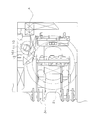
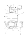
- the principal part top view of the hydraulic shovel of FIG. The figure which shows the external appearance of the turning apparatus of the hydraulic shovel of FIG.
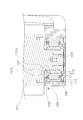
- the figure which shows the internal structure of the turning apparatus of FIG. The elements on larger scale of the turning apparatus of FIG.
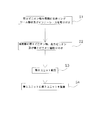
- the W section enlarged view of FIG. The flowchart which shows the manufacturing method of the turning apparatus shown in FIG.
- FIG. (B) The figure which shows the manufacturing method of the turning apparatus shown in FIG. (A) Enlarged view of T portion of FIG. 9 (a), (b) Enlarged view of seal member, (c) Enlarged view of protruding portion.
- FIG. 1 is a side view of a hydraulic excavator according to the present embodiment.
- FIG. 2 is a partial plan view excluding the working machine of the hydraulic excavator according to the present embodiment.
- a hydraulic excavator 1 as an example of a work vehicle includes a lower traveling body 2 having crawler belts 20 provided at both left and right ends in the traveling direction, and an upper turn disposed on the upper portion of the lower traveling body 2.
- the body 3 is provided.
- the upper swing body 3 is provided with a work machine 30, an operator cab 31, an engine room 32, a counterweight 33, and the like.
- the work machine 30 includes a boom 301 bent at a central portion, an arm 302 attached to the tip of the boom 301, and a bucket 303 attached to the tip of the arm 302. Further, as shown in FIG. 2, a work machine support shaft 34 for mounting the work machine 30 is provided. As shown in FIG.
- a turning device 10 is provided on the upper swing body 3 in order to rotate the upper swing body 3 with respect to the lower traveling body 2.
- a passage 4 is provided in the vicinity of the periphery of the upper swing body 3. The passage 4 is installed in each part of the excavator 1 for maintenance and the like so that an operator can safely come and go.
- FIG. 3 is a side view of the turning device 10 according to the first embodiment.
- the swing device 10 of the upper swing body 3 includes a drive unit 11 provided on the upper part, a swing machinery 12 provided on the lower side of the drive unit 11, and the drive unit 11.
- an output unit 13 provided below the swing machinery 12 is provided.
- the drive unit 11 includes a swing motor that is a hydraulic motor, a control valve that controls the hydraulic motor, and the like.
- the lower traveling body 2 is provided with a swing circle 21 having teeth on the outer periphery, and the output pinion 101 provided in the output unit 13 meshes with the swing circle 21. ing.
- the rotation of the swing motor is decelerated by the speed reduction unit disposed inside the swing machinery 12 and transmitted to the output pinion 101 so that the output pinion 101 rotates.
- the turning device 10 rotates the outer periphery of the swing circle 21, and the upper turning body 3 to which the turning device 10 is fixed turns with respect to the lower traveling body 2.
- FIG. 4 is a cross-sectional view showing the main parts of the turning device 10, and is a cross-sectional view showing the main parts of the swing machinery 12 and the output unit 13.
- the swing machinery 12 includes a shaft coupling portion 14, a brake portion 15, and a speed reduction portion 16 that are continuously provided from above to below.
- the shaft coupling unit 14 mechanically couples the swing motor disposed in the drive unit 11 and the drive shaft 17 of the swing machinery 12.
- the brake unit 15 brakes the rotation of the drive shaft 17.
- the rotation of the drive shaft 17 is decelerated by the internal deceleration mechanism and output to the output pinion 101.
- a swing machinery including a drive unit 11 including a control valve and a swing motor, a shaft coupling unit 14, a brake unit 15, and a speed reduction unit 16 in the vertical direction from above to below. 12 and the output unit 13 are continuously arranged, so that the swivel device 10 has a vertically long shape.
- the output unit 13 includes an output pinion 101, a first pinion shaft 102, a second pinion shaft 103, a first bearing unit 104, a second bearing unit 105, a case unit 106, a support ring 107, and a seal member. 108 (see FIG. 5 described later).
- the output pinion 101 has a rotation axis in the vertical direction and meshes with the swing circle 21.
- the first pinion shaft 102 is provided upward from the upper surface 101 a of the output pinion 101.
- the second pinion shaft 103 is provided downward from the lower surface 101 b of the output pinion 101.
- the output pinion 101 rotates integrally with the first pinion shaft 102 and the second pinion shaft 103 as rotation axes.
- the 1st bearing part 104 supports the 1st pinion shaft 102 rotatably.
- the 2nd bearing part 105 supports the 2nd pinion shaft 103 rotatably. That is, the output pinion 101 is pivotally supported on both the upper side and the lower side thereof.
- the case portion 106 is formed so as to cover the periphery and the lower side of the second bearing portion 105.
- the case portion 106 is filled with grease for lubricating the second bearing portion 105.
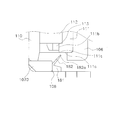
- FIG. 5 is a cross-sectional view showing the periphery of the second bearing portion 105
- FIG. 6 is an enlarged view of the W portion in FIG.
- the second bearing portion 105 includes an inner race 110, an outer race 111, a roller 112, and a cage 113 that holds the roller 112.
- the inner race 110 is provided around the second pinion shaft 103 in contact with the second pinion shaft 103 and rotates together with the second pinion shaft 103.
- the outer race 111 is disposed outside the inner race 110 and is fixed to the case portion 106.
- the roller 112 is disposed between the inner race 110 and the outer race 111 so as to be rollable by a cage 113.
- the support ring 107 is disposed between the upper end surface 110a of the inner race 110 of the second pinion shaft 103 and the lower surface 101b of the output pinion 101 in contact with the upper end surface 110a and the lower surface 101b. .
- the position of the output pinion 101 can be positioned above the inner race 110 by the height of the support ring 107 in the vertical direction. Thereby, the output pinion 101 can be supported at a position above the case portion 106 so as not to contact the case portion 106.
- the support ring 107 rotates with the second pinion shaft 103.
- the lower end 107u of the support ring 107 is provided with a protruding portion 117 that protrudes outward from the outer peripheral surface 107a.
- the protrusion 117 is formed over the entire circumference of the support ring 107.
- the seal member 108 is an elastic member formed of a resin such as rubber, and is attached to the outer peripheral surface 107a of the support ring 107 as shown in FIG.
- the seal member 108 includes a cylindrical mounting portion 181 mounted in contact with the outer peripheral surface 107a of the support ring 107, and a lip portion 182 formed to protrude outward from the lower end of the mounting portion 181. have.
- the lip portion 182 is formed over the entire circumference of the seal member 108.
- the mounting portion 181 is mounted on the upper side of the protruding portion 117 of the support ring 107.
- the lip portion 182 projects outward from the projecting portion 117 and is inclined downward, and the tip 182 a presses the upper end surface 111 a of the outer race 111.
- the seal member 108 rotates simultaneously with the second pinion shaft 103 together with the support ring 107.
- the lip portion 182 contacts the protruding portion 117 at the contact portion 117 a, and a gap S is formed between the lip portion 182 and the protruding portion 117. More specifically, as shown in the enlarged view of the V part in FIG.
- an abutting portion 117 with which the lip 182 abuts is located above the vicinity of the tip of the projecting portion 117 provided at the lower end 107 u of the support ring 107. Is formed. Further, the gap S is formed between an upper side 117 s from the base portion 117 b of the protruding portion 117 to the contact portion 117 a and the lip portion 182. Since the top end 182a of the lip portion 182 presses the upper end surface 111a of the outer race 111, the upper side of the second bearing portion 105 is covered and sealed by the support ring 107 and the seal member 108. It is possible to prevent scattering and entry of foreign matter.
- FIG. 7 is a flowchart for explaining the method of manufacturing the swivel device of this embodiment.
- FIG. 8 is a view for explaining the method of manufacturing the turning device of the present embodiment.
- each structure of a turning apparatus is arrange
- the first unit 1000 and the second unit 1001 are assembled.
- the support ring 107, the seal member 108, and the inner race 110 are attached around the second pinion shaft 103.
- the seal member 108 is attached to the outer peripheral surface 107 a of the support ring 107 before or after the support ring 107 is attached to the second pinion shaft 103.
- the inner race 110 is attached to the second pinion shaft 103 so as to contact the support ring 207.
- the first pinion shaft 102, the output pinion 101, and the second pinion shaft 103 are attached to the speed reduction unit 16.
- the speed reduction unit 16 is arranged upside down, and the first pinion shaft 102, the output pinion 101, and the second pinion shaft 103 are attached from above the speed reduction unit 16.
- the first unit 1000 including the speed reducing portion 16, the first pinion shaft 102, the output pinion 101, the second pinion shaft 103, the support ring 107, the seal member 108, and the inner race 110 is provided. Are assembled (see FIG. 8).
- the second unit 1001 is mounted on the first unit 1000 from above.
- the first unit 1000 is arranged upside down, and the second pinion shaft 103 protrudes upward.
- the second unit 1001 is also arranged upside down, and is attached to the first unit 1000 so that the outer race 111 is arranged around the inner race 110 attached to the second pinion shaft 103.
- the second unit 1001 is moved downward from above with the central axis of the inner race 110 (see A in the figure) and the central axis of the outer race 111 (see A in the figure) substantially coincided with each other. Moved.
- FIG. 9A is a diagram showing a state of the seal member 108 before the second unit 1001 is attached to the first unit 1000.
- FIG. 9B is a diagram illustrating a state of the seal member 108 after the second unit 1001 is attached to the first unit 1000.
- 10A is an enlarged view of a T portion of FIG. 9A
- FIG. 10B is a cross-sectional view showing a state of the seal member 108 before being attached to the support ring 107.
- the lip portion 182 of the seal member 108 protrudes obliquely downward from the vertical direction of the central axis A of the seal member 108.
- the lip portion 182 moves further obliquely so that the tip 182a approaches the center axis A side as a result of elastic deformation. (See arrow B). This movement is stopped when the lip portion 182 contacts the protruding portion 117. 9 and 10, the support ring 107 and the seal member 108 are disposed upside down.
- the support ring 107 and the seal member 108 are supported in the same manner as in the state of FIG.
- An abutting portion 117 a with which the lip 182 abuts is formed on the upper side in the vicinity of the tip of the protruding portion 117 provided at the lower end of the ring 107. Further, a gap S is formed between the upper side 117 s from the base portion 117 b of the protruding portion 117 to the contact portion 117 a and the lip portion 182.
- the seal member 108 is provided along the upper side 117 s of the projecting portion 117 so that the clearance S is provided between the seal ring 108 and the support ring 107 and the lip portion 182 is attached to the support ring 107 so as to contact the projecting portion 117. It is easier to adjust the position of the tip 182a of the lip part 182 than arranging the lip part 182 on the front side. Further, in the abutting portion 117a, the surface of the projecting portion 117 has a two-step R shape so that the lip portion 182 is not damaged. Specifically, as shown in the enlarged view of FIG.
- the upper side 117s of the protruding portion 117 has a predetermined length (indicated by a in the drawing) in the vertical direction from the outer peripheral surface 107a to the outer peripheral surface 107a in front view. From there, an R shape is formed with a radius R1, and then an R shape is formed with a radius R2.
- the center position O1 of R1 is on a line L1 perpendicular to the lower end surface 117v of the protrusion 117 from a position moved from the outer peripheral surface 107a by a predetermined length a in the direction perpendicular to the outer peripheral surface 107a. , A position moved by a length b downward from the lower end surface 117v.
- An abutting portion 117a with which the lip portion 182 abuts is located in the vicinity of the portion that switches from R1 to R2.
- R1 has a larger diameter than R2.
- the center position O2 of R2 will be described.
- the center position O2 is provided so as to be tangent to a straight line 117L shown in FIG. More specifically, as shown in FIG. 10C, the intersection of the outer peripheral surface 107a of the support ring 107 and the upper side 117s of the protrusion 117 is indicated as A.
- a straight line on the lower end side of the lip portion 182 of the seal member 108 not attached to the support ring 107 is indicated by 182L.
- a straight line passing through A and having a slope of the straight line 182L is indicated as 117L.
- a center position O2 of a circle having a radius R2 is provided so as to be tangent to the straight line 117L.
- the intersection of the straight line 117L and the extension line of the tip 117d is indicated by B.
- the diameter Ra of the tip 182a is longer than the diameter Rc of the tip 117d of the protrusion 117, and is longer than the inner diameter Rb of the outer race 111 (the inner peripheral surface is shown as 111b).
- the position of the tip 182a of the lip portion 182 is as shown in FIG.
- the outer race 111 is located outside the inner peripheral surface 111b and below the upper end surface 111a.
- the tip 182a of the lip portion 182 abuts on the upper end surface 111a of the outer race 111, and the upper side of the second bearing portion 105 can be sealed.
- the fourth step S4 as shown in FIGS.
- the case portion 106 is disposed outside the seal member 108, so that the seal state of the seal member 108 is not visually observed.
- the tip position of the lip portion 182 is arranged at a position facing the upper end surface 111a of the outer race 111, even if it cannot be visually observed, the sealing performance is surely ensured. Can do.
- the lip portion 182 abuts on the projecting portion 117 and the abutting portion 117 a, and a gap S is formed between the lip portion 182 and the projecting portion 117. Is formed.
- a turning device 10 for a work vehicle includes a drive unit 11, a reduction unit 16, an output pinion 101, a first pinion shaft 102, a second pinion shaft 103, and a second bearing unit 105 (the bearing unit). An example), a case portion 106, a support ring 107, and a seal member 108.
- the deceleration unit 16 is disposed below the drive unit 16 and decelerates the rotation of the drive unit 16.
- the output pinion 101 is disposed below the speed reduction unit 16 and outputs the rotation of the drive unit 16 decelerated by the speed reduction unit 16.
- the first pinion shaft 102 is provided upward from the upper surface 101 a of the output pinion 101.
- the second pinion shaft 103 is provided downward from the lower surface 101b of the output pinion.
- the 2nd bearing part 105 supports the 2nd pinion shaft 103 rotatably.
- the case part 106 is provided so as to cover the lower side and the periphery of the second bearing part 105.
- the support ring 107 is disposed between the second bearing portion 105 and the output pinion 101 of the second pinion shaft 103, and abuts against each of the second bearing portion 105 and the output pinion 101 to place the output pinion 101 in the second bearing portion 105. Support above.
- the seal member 108 includes a mounting portion 181 disposed on the outer peripheral surface 107 a of the support ring 107, and a lip portion 182 that is formed to protrude radially outward from the mounting portion 181 and seals the upper side of the second bearing portion 105.
- the support ring 107 has a projecting portion 117 that projects from the lower end 107u toward the radially outer side.
- the mounting portion 181 is disposed above the protruding portion 117, and the lip portion 182 protrudes outward from the protruding portion 117.
- FIG. 11 is a diagram illustrating a state in which the second unit 1001 is attached to the first unit 1000 when the support ring 1070 having no protrusion 117 is used.
- the lip portion 182 has moved too much upward due to elastic deformation, so that the tip 182a of the lip portion 182 is located within the upper end surface 111a of the outer race 111. Since it faces the vicinity of the end 111c on the peripheral surface 111b side, it may be difficult to contact the upper end surface 111a of the outer race 111.
- the lip portion 182 contacts the protruding portion 117 and the change in angle is suppressed. Therefore, even if the case portion 106 cannot visually recognize the lip portion 182 of the seal member 108, the lip portion 182 can be disposed at an appropriate position (upper end surface 111a). Thereby, it becomes possible to ensure sealing performance more reliably.
- the second bearing portion 105 includes an inner race 110 (an example of an inner ring), an outer race 111 (an example of an outer ring), and a roller 112 (an example of a rolling element). is doing.
- the outer race 111 abuts on the second pinion shaft 103 and rotates together with the second pinion shaft 103.
- the outer race 111 is disposed on the outer peripheral side of the inner race 110 and is fixed to the case portion 106.
- the roller 112 is disposed between the inner race 110 and the outer race 111 so as to be able to roll.
- the lip portion 182 is in contact with the upper end surface 111 a of the outer race 111.
- the lip portion 182 of the seal member 109 abuts on the upper end surface 111a of the outer race 111, so that the support ring 107 and the seal member 108 are connected to the upper side of the second bearing portion 105, particularly the outer race 111 and the inner race 110. It is possible to cover the gap from above and seal it, and it is possible to prevent grease from scattering and foreign matter from entering.
- the protrusion 117 is provided over the entire circumference of the support ring 107.
- the manufacturing method of the turning device 10 for a work vehicle includes a first step S1 and a second step S2 (an example of a first unit assembly step), a third step S3 (an example of a second unit assembly step), And a fourth step (an example of a mounting step).
- the first unit 1000 including the speed reducing portion 16, the first pinion shaft 102, the output pinion 101, the second pinion shaft 103, the support ring 107, the seal member 108, and the inner race 110 is provided. assemble.
- the support ring 107, the seal member 108, and the inner race 110 are attached around the second pinion shaft 103.
- the second step S ⁇ b> 2 (an example of the second attachment operation)
- the first pinion shaft 102, the output pinion 101, and the second pinion shaft 103 are attached to the speed reduction unit 16.
- the outer unit 111 and the roller 112 are attached to the case unit 106 to assemble the second unit 1001.
- the fourth step S4 the second unit 1001 arranged upside down is mounted from the upper side of the first unit 1000 arranged upside down so that the outer race 111 is arranged outside the inner race 110.
- the diameter Rc of the tip 117d of the protrusion 117 is smaller than the inner diameter Rb of the outer race 111, and the diameter Ra of the tip 182a of the lip 182 attached around the support ring 107 is larger than the inner diameter Rb of the outer race 111. .
- the lip portion 182 contacts the protruding portion 117, and the change in angle is suppressed. Therefore, the diameter Ra of the tip 182 a of the lip portion 182 is larger than the inner diameter Rb of the outer race 111. Therefore, in the fourth step S4, even when the contact state of the seal member 108 cannot be visually recognized by the case portion 106, the lip portion 106 can be brought into contact with the upper end surface 111a of the outer race 111 more reliably. It becomes possible to ensure sealing performance.
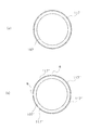
- the protrusion 117 is provided over the entire circumference of the support ring 107 as shown in FIG. 12A, but may not be provided over the entire circumference. Good.
- a plurality of projecting portions 117 ′ may be divided and a gap Q may be formed between the projecting portions 117 ′.
- the tip 182 a of the lip 182 of the seal member 108 is in contact with the upper end surface 111 a of the outer race 111, but it is not limited to the upper end surface 111 a of the outer race 111.
- the tip 182 a of the lip portion 182 is formed on the upper surface 106 a ′ of the extended flange portion 106 b ′. May be in contact. Even in this case, it is possible to prevent the grease from jumping out from the second bearing portion 105 or the foreign matter from entering the second bearing portion 105.
- the teeth are formed outside the swing circle 21 and the turning device 10 rotates outside the swing circle 21.
- the teeth are formed inside the swing circle 21 and the turning device 10. May be configured to rotate inside the swing circle 21.
- the lip portion 182 is in contact with the protruding portion 117 in both the state before manufacture (see FIG. 10A) and the state of the swivel device 10 after manufacture (see FIG. 6). In the state after manufacture, the lip portion 182 may not be in contact with the protruding portion 117.
- the swivel device of the hydraulic excavator has been described as an example. However, the present invention is not limited to this, and the present invention can be applied not only to a hydraulic excavator but also to a work vehicle having a turning portion in another vehicle body.
- the working vehicle turning device according to the present invention has an effect of ensuring the sealing performance more reliably, it is widely applicable to various working vehicle turning devices such as hydraulic excavators.
Landscapes
- Engineering & Computer Science (AREA)
- General Engineering & Computer Science (AREA)
- Mechanical Engineering (AREA)
- Mining & Mineral Resources (AREA)
- Civil Engineering (AREA)
- Structural Engineering (AREA)
- Sealing Of Bearings (AREA)
- Sealing With Elastic Sealing Lips (AREA)
- Mounting Of Bearings Or Others (AREA)
- Rolling Contact Bearings (AREA)
Abstract
Description
下部走行体に対して上部旋回体を旋回させるために、旋回装置としてスイングモータを備えたスイングマシナリが上部旋回体に設けられている。一方、下部走行体にはスイングサークルが設けられている。スイングマシナリには、スイングモータからの回転駆動力を減速する減速部、ブレーキ部及び出力ピニオンなどが設けられており、出力ピニオンがスイングサークルの内側又は外側に設けられている歯と噛合っている。スイングモータの回転駆動力が出力ピニオンに伝達され、スイングマシナリがスイングサークルの内側又は外側を回転移動することによって、下部走行体に対して上部旋回体が旋回する。
出力ピニオンの下側に配置されている第2軸受け部は下方からケース部によって覆われており、そのケース部内には軸受けの潤滑のためにグリースが充填されている。一方、第2軸受け部の上方はケースによって覆われていないため、上方から外部へのグリースの飛散、又は上方からの土砂、水等の浸入を防止するために第2軸受け部の上側にはシール部材が設けられている。
しかしながら、上記従来の作業車両の旋回装置では、以下に示すような問題点を有している。
上記旋回装置を製造する際に、シール部材を第2ピニオン軸の周囲に組み付けるとシール部材が弾性変形し、そのリップ部の角度が変化する場合があった。又、第2軸受け部を覆っているケースによって、製造の際にシール部材の当接状態を視認出来ない。
このため、リップ部の角度が極端に変化した場合には、製造後の旋回装置においてシール部材のリップ部が適切な位置に配置されず、シール性を損ねる場合があった。
本発明の目的は、従来の作業車両の旋回装置の課題を考慮し、より確実にシール性を確保することが可能な作業車両の旋回装置及びその製造方法を提供することである。
第1の発明に係る作業車両の旋回装置は、駆動部と、減速部と、出力ピニオンと、第1ピニオン軸と、第2ピニオン軸と、軸受け部と、ケース部と、支持リングと、シール部材とを備えている。駆動部は、旋回の回転駆動力を発生する。減速部は、駆動部の下方に配置され、駆動部の回転を減速する。出力ピニオンは、減速部の下方に配置され、減速部によって減速された駆動部の回転を出力する。第1ピニオン軸は、出力ピニオンの上面から上方に向かって設けられ、減速部を介して駆動部の回転が伝達される。第2ピニオン軸は、出力ピニオンの下面から下方に向かって設けられている。軸受け部は、第2ピニオン軸を回転可能に支持する。ケース部は、軸受け部の下側及び周囲を覆うように設けられている。支持リングは、第2ピニオン軸の軸受け部と出力ピニオンの間に配置され、軸受け部と出力ピニオンの夫々に当接して出力ピニオンを軸受け部の上方に支持する。シール部材は、支持リングの外周に配置される装着部と、装着部から径方向外側に向かって突出して形成され軸受け部の上側を封止するリップ部とを有する。支持リングは、その下端から径方向外側に向かって突出して設けられた突出部を有している。装着部は、突出部よりも上側に配置され、リップ部は、突出部よりも外側に突出している。
しかしながら、上記のように突出部を設けることにより、リップ部の角度が変化する場合であってもリップ部が突出部に当接して角度変化が抑制される。
そのため、例えケース部によって視認できない場合であってもシール部材のリップ部を適切な位置に配置することができる。
これにより、より確実にシール性を確保することが可能となる。
このように、シール部材のリップ部が外輪の上端面に当接することにより、支持リングとシール部材によって軸受け部の上側、特に外輪と内輪の間を上方から覆って封止することが出来、グリースの飛散、異物の侵入を防ぐことが可能となる。
これによって、シール部材を支持リングに嵌めることによるリップ部の角度の変化が全周に渡って抑制され、リップ部による封止位置を適切な位置に定めることが出来る。
このように、支持リングの周囲にシール部材が取り付けられて、リップ部の角度が変化する場合であってもリップ部が突出部に当接して角度変化が抑制されるため、リップ部の先端の径は外輪の内径よりも大きくなっている。そのため、装着工程において、ケース部によってシール部材の当接状態が視認できない場合であっても、リップ部を外輪の上端面により確実に当接させることができ、シール性を確保することが可能となる。
本発明によれば、より確実にシール性を確保することが可能な作業車両の旋回装置及びその製造方法を提供することが出来る。
(実施形態)
<1.構成>
図1は、本実施の形態の油圧ショベルの側面図である。図2は、本実施の形態の油圧ショベルの作業機を除く部分平面図である。
そして、図2に示すように、下部走行体2に対して上部旋回体3を旋回させるために、上部旋回体3には旋回装置10が設けられている。また、上部旋回体3の周囲近傍には通路4が設けられている。この通路4は、メンテナンス等のために油圧ショベル1の各部分に作業者が安全に行き来可能なように設置されている。
図3は、本実施の形態1の旋回装置10の側面図である。図2及び図3に示すように、上部旋回体3の旋回装置10は、その上部に設けられた駆動部11と、駆動部11の下側に設けられたスイングマシナリ12と、駆動部11から入力された動力を出力するために、スイングマシナリ12の下側に設けられた出力部13を備えている。この駆動部11には、油圧モータであるスイングモータ及び油圧モータを制御する制御弁等が配置されている。
スイングモータの回転が、スイングマシナリ12の内部に配置されている減速部によって減速されて出力ピニオン101に伝達されて出力ピニオン101が回転する。この回転によって旋回装置10は、スイングサークル21の外周を回転し、旋回装置10が固定されている上部旋回体3が下部走行体2に対して旋回する。
図4に示すように、スイングマシナリ12には、軸結合部14と、ブレーキ部15と、減速部16が、上方から下方に向かって連続して設けられている。
軸結合部14では、駆動部11に配置されているスイングモータとスイングマシナリ12の駆動軸17との機械的結合が行なわれる。ブレーキ部15は、駆動軸17の回転を制動する。減速部16では、内部の減速機構によって駆動軸17の回転が減速されて出力ピニオン101へと出力される。
出力部13は、出力ピニオン101と、第1ピニオン軸102と、第2ピニオン軸103と、第1軸受け部104と、第2軸受け部105と、ケース部106と、支持リング107と、シール部材108(後述する図5参照)とを有している。
出力ピニオン101は、上下方向に回転軸を有しており、スイングサークル21と噛み合う。
第1ピニオン軸102は、出力ピニオン101の上面101aから上方に向かって設けられている。第2ピニオン軸103は、出力ピニオン101の下面101bから下方に向かって設けられている。出力ピニオン101は、第1ピニオン軸102及び第2ピニオン軸103を回転軸として一体的に回転する。
ケース部106は、第2軸受け部105の周囲及び下側を覆うように形成されている。このケース部106内には、第2軸受け部105の潤滑のためのグリースが充填されている。
インナーレース110は、図6及び図7に示すように第2ピニオン軸103の周囲に第2ピニオン軸103に当接して設けられており、第2ピニオン軸103とともに回転する。
コロ112は、図6に示すように、インナーレース110とアウターレース111の間に保持器113によって転動可能に保持されて配置されている。
支持リング107が、図6に示すように、第2ピニオン軸103のインナーレース110の上端面110aと出力ピニオン101の下面101bの間に、上端面110a及び下面101bと当接して配置されている。支持リング107が配置されることによって出力ピニオン101の位置を、インナーレース110から支持リング107の上下方向の高さ分上方に位置させることができる。これにより、出力ピニオン101を、ケース部106と接触しないようにケース部106の上方の位置に支持することができる。
シール部材108は、ゴム等の樹脂によって形成された弾性を有する部材であり、図6に示すように支持リング107の外周面107aに装着されている。詳細には、シール部材108は、支持リング107の外周面107aに当接して装着される筒状の装着部181と、装着部181の下端から外側に向かって突出して形成されたリップ部182とを有している。リップ部182は、シール部材108の全周に渡って形成されている。
また、図6に示すように、リップ部182が突出部117と当接部分117aにおいて当接するとともに、リップ部182と突出部117の間に隙間Sが形成されている。より詳細には、図6のV部拡大図に示すように支持リング107の下端107uに設けられている突出部117の先端近傍の上側に、リップ部182が当接している当接部分117が形成されている。また、隙間Sは、突出部117の根元部分117bから当接部分117aまでの上側117sと、リップ部182の間に形成されている。
このリップ部182の先端182aがアウターレース111の上端面111aを押圧することによって、第2軸受け部105の上側は支持リング107及びシール部材108によって覆われて封止されているため、グリースの外部への飛散、異物の侵入を防ぐことができる。
次に、本実施形態の旋回装置の製造方法について説明する。図7は、本実施形態の旋回装置の製造方法を説明するためのフロー図である。図8は、本実施形態の旋回装置の製造方法を説明するための図である。尚、図8では、旋回装置の各構成が使用時と上下逆に配置されているが、以下の説明の際に記載する上下方向とは、使用時の際の配置を基準に説明する。すなわち、図8における上方が、使用時における下方となる。以下、上下逆に配置された状態を示す図面においても同様である。
はじめに、第1工程S1において、第2ピニオン軸103の周囲に支持リング107、シール部材108及びインナーレース110が取り付けられる。シール部材108は、第2ピニオン軸103に支持リング107を取り付ける前又は取り付けた後に支持リング107の外周面107aにシール部材108が装着される。そして、インナーレース110は、支持リング207に当接するように、第2ピニオン軸103に取り付けられる。
この第1工程S1及び第2工程S2によって、減速部16、第1ピニオン軸102、出力ピニオン101、第2ピニオン軸103、支持リング107、シール部材108、及びインナーレース110を有する第1ユニット1000が組み立てられる(図8参照)。
次に、第4工程S4において、第1ユニット1000に第2ユニット1001が上方から装着される。図8に示すように、第1ユニット1000は、上下逆に配置されており、第2ピニオン軸103が上方に向かって突出している。第2ユニット1001も上下逆に配置されており、第2ピニオン軸103に取り付けられているインナーレース110の周囲にアウターレース111が配置されるように、第1ユニット1000に装着される。この際、図8に示すように、インナーレース110の中心軸(図中A参照)とアウターレース111の中心軸(図中A参照)が略一致した状態で上方から第2ユニット1001が下方に移動される。
また、この当接部分117aでは、突出部117の表面には2段階のR形状が施されており、リップ部182に傷か付かないように形成されている。詳細には、図10(c)の拡大図に示すように、突出部117の上側117sは正面視において外周面107aから外周面107aに対して垂直方向に所定の長さ(図中aで示している)まで直線に形成されており、そこから半径R1でR形状が形成され、続いて半径R2でR形状が形成されている。
より詳しく説明すると、図10(c)に示すように、支持リング107の外周面107aと突出部117の上側117sの交点が、Aとして示されている。一方、図10(b)に示すように、支持リング107に取り付けられていない状態のシール部材108のリップ部182の下端側の直線が182Lで示されている。そして、Aを通り、直線182Lの傾きを有する直線が117Lとして示されている。この直線117Lに正接するように半径R2の円の中心位置O2が設けられている。尚、直線117Lと、先端117dの延長線の交点がBで示されている。
この状態で、第2ユニット1001を下方に移動させると、リップ部182の先端182aは、アウターレース111の上端面111aに当接し、第2軸受け部105の上側をシールすることが出来る。尚、この第4工程S4において、図9(a)及び図9(b)に示すように、ケース部106がシール部材108の外側に配置されているため、シール部材108のシール状態を目視では確認しにくいが、本実施形態では、リップ部182の先端位置がアウターレース111の上端面111aと対向する位置に配置されているため、たとえ目視できなくても、確実にシール性を確保することができる。
尚、図6において説明したように製造された状態の旋回装置10においても、リップ部182が突出部117と当接部117aにおいて当接するとともに、リップ部182と突出部117の間に隙間Sが形成されている。
(3-1)
本実施形態の作業車両の旋回装置10は、駆動部11と、減速部16と、出力ピニオン101と、第1ピニオン軸102と、第2ピニオン軸103と、第2軸受け部105(軸受け部の一例)と、ケース部106と、支持リング107と、シール部材108とを備えている。減速部16は、駆動部16の下方に配置され、駆動部16の回転を減速する。出力ピニオン101は、減速部16の下方に配置され、減速部16によって減速された駆動部16の回転を出力する。第1ピニオン軸102は、出力ピニオン101の上面101aから上方に向かって設けられている。第2ピニオン軸103は、出力ピニオンの下面101bから下方に向かって設けられている。第2軸受け部105は、第2ピニオン軸103を回転可能に支持する。ケース部106は、第2軸受け部105の下側及び周囲を覆うように設けられている。支持リング107は、第2ピニオン軸103の第2軸受け部105と出力ピニオン101の間に配置され、第2軸受け部105と出力ピニオン101の夫々に当接して出力ピニオン101を第2軸受け部105の上方に支持する。シール部材108は、支持リング107の外周面107aに配置される装着部181と、装着部181から径方向外側に向かって突出して形成され第2軸受け部105の上側を封止するリップ部182とを有する。支持リング107は、その下端107uから径方向外側に向かって突出して設けられた突出部117を有している。装着部181は、突出部117よりも上側に配置され、リップ部182は、突出部117よりも外側に突出している。
例えば、図11は、突出部117が形成されていない支持リング1070を用いた場合に、第2ユニット1001を第1ユニット1000に装着する状態を示す図である。図11に示すように、突出部117が設けられていないため、リップ部182が弾性変形によって上方に移動しすぎているため、リップ部182の先端182aが、アウターレース111の上端面111aの内周面111b側の端111c近傍に対向しているため、アウターレース111の上端面111aに当接させ難い場合がある。
そのため、例えケース部106によって視認できない場合であってもシール部材108のリップ部182を適切な位置(上端面111a)に配置することができる。
これにより、より確実にシール性を確保することが可能となる。
本実施形態の作業車両の旋回装置10では、第2軸受け部105は、インナーレース110(内輪の一例)と、アウターレース111(外輪の一例)と、コロ112(転動体の一例)とを有している。アウターレース111は、第2ピニオン軸103に当接し、第2ピニオン軸103とともに回転する。アウターレース111は、インナーレース110の外周側に配置され、ケース部106に固定されている、コロ112は、インナーレース110とアウターレース111の間に転動可能に配置されている。リップ部182は、アウターレース111の上端面111aに当接している。
このように、シール部材109のリップ部182がアウターレース111の上端面111aに当接することにより、支持リング107とシール部材108によって第2軸受け部105の上側、特にアウターレース111とインナーレース110の間を上方から覆って封止することが出来、グリースの飛散、異物の侵入を防ぐことが可能となる。
本実施形態の作業車両の旋回装置10では、突出部117は、支持リング107の全周に渡って設けられている。
これによって、シール部材108を支持リング107に嵌めることによるリップ部182の角度の変化をより確実に抑制でき、リップ部182による封止位置を適切な位置に定めることが出来る。
本実施形態の作業車両の旋回装置10の製造方法は、第1工程S1及び第2工程S2(第1ユニット組立工程の一例)と、第3工程S3(第2ユニット組立工程の一例)と、第4工程(装着工程の一例)とを備えている。第1工程S1及び第2工程S2では、減速部16、第1ピニオン軸102、出力ピニオン101、第2ピニオン軸103、支持リング107、シール部材108、及びインナーレース110を有する第1ユニット1000を組み立てる。第1工程S1(第1取り付け動作の一例)では、第2ピニオン軸103の周囲に支持リング107、シール部材108、及びインナーレース110を取り付ける。第2工程S2(第2取り付け動作の一例)では、減速部16に第1ピニオン軸102、出力ピニオン101及び第2ピニオン軸103を取り付ける。第3工程S3では、ケース部106にアウターレース111及びコロ112を取り付けて第2ユニット1001を組み立てる。第4工程S4は、上下逆に配置された第1ユニット1000の上側から、上下逆に配置された第2ユニット1001を、インナーレース110の外側にアウターレース111が配置されるように装着する。突出部117の先端117dの径Rcはアウターレース111の内径Rbよりも小さく、支持リング107の周囲に取り付けられた状態におけるリップ部182の先端182aの径Raはアウターレース111の内径Rbよりも大きい。
以上、本発明の一実施形態について説明したが、本発明は上記実施形態に限定されるものではなく、発明の要旨を逸脱しない範囲で種々の変更が可能である。
(A)
上記実施形態における支持リング107では、突出部117は、図12(a)に示すように、支持リング107の全周に渡って設けられていたが、全周に渡って設けられていなくてもよい。
例えば、図12(b)の支持リング107´に示すように、分割して複数の突出部117´が形成されており、突出部117´の間に隙間Qが形成されていてもよい。
上記実施形態では、シール部材108のリップ部182の先端182aは、アウターレース111の上端面111aに当接していたが、アウターレース111の上端面111aに限られなくてもよい。例えば、図13に示すように、ケース部106´がアウターレース111側に延びた庇部106b´を有している場合、その延びた庇部106b´の上面106a´にリップ部182の先端182aが当接していてもよい。
この場合であっても、第2軸受け部105からのグリースの飛び出し若しくは、第2軸受け部105への異物の侵入を防ぐことができる。
又、上記実施の形態では、スイングサークル21の外側に歯が形成され、旋回装置10がスイングサークル21の外側を回転する構成であるが、スイングサークル21の内側に歯が形成され、旋回装置10がスイングサークル21の内側を回転する構成であってもよい。
上記実施形態では、第1工程S1の後に第2工程S2を行っていたが、第2工程S2を第1工程S1の前に行なっても良い。すなわち、第1ピニオン軸102、出力ピニオン101、及び第2ピニオン軸103を減速部16に取り付けた後に、支持リング107、シール部材108及びインナーレース110を第2ピニオン軸103の取り付けても良い。
上記実施形態では、製造する前の状態(図10(a)参照)と製造後の旋回装置10の状態(図6参照)の両方において、リップ部182が突出部117と当接しているが、製造後の状態では、リップ部182が突出部117と当接していなくてもよい。
(F)
上記実施の形態では、油圧ショベルの旋回装置を例として挙げて説明した。しかし、本発明はこれに限定されるものではなく、油圧ショベルに限らず他の車体に旋回部を持つ作業車両に対しても、本発明の適用は可能である。
2 下部走行体
3 上部旋回体
4 通路
10 旋回装置
11 駆動部
12 スイングマシナリ
13 出力部
14 軸結合部
15 ブレーキ部
16 減速部
17 駆動軸
20 履帯
21 スイングサークル
30 作業機
31 運転席
32 エンジンルーム
33 カウンタウエイト
34 作業機支持軸
101 出力ピニオン
101a 上面
101b 下面
102 第1ピニオン軸
103 第2ピニオン軸
104 第1軸受け部
105 第2軸受け部(軸受け部の一例)
106 ケース部
106´a 上面
106´b 庇部
107 支持リング
107a 外周面
108 シール部材
110 インナーレース(内輪の一例)
110a 上端面
111 アウターレース(外輪の一例)
111a 上端面
111b 内周面
111c 端
112 コロ(転動体の一例)
113 保持器
117 突出部
117a 当接部分
117s 上側
117d 先端
117b 根元部分
181 装着部
182 リップ部
182a 先端
301 ブーム
302 アーム
303 バケット
1000 第1ユニット
1001 第2ユニット
1070支持リング
Claims (4)
- 旋回の回転駆動力を発生する駆動部と、
前記駆動部の下方に配置され、前記駆動部の回転を減速する減速部と、
前記減速部の下方に配置され、前記減速部によって減速された前記駆動部の回転を出力する出力ピニオンと、
前記出力ピニオンの上面から上方に向かって設けられ、前記減速部を介して前記駆動部の回転が伝達される第1ピニオン軸と、
前記出力ピニオンの下面から下方に向かって設けられた第2ピニオン軸と、
前記第2ピニオン軸を回転可能に支持する軸受け部と、
前記軸受け部の下側及び周囲を覆うように設けられているケース部と、
前記第2ピニオン軸の前記軸受け部と前記出力ピニオンの間に配置され、前記軸受け部と前記出力ピニオンの夫々に当接して前記出力ピニオンを前記軸受け部の上方に支持する支持リングと、
前記支持リングの外周に配置される装着部と、前記装着部から径方向外側に向かって突出して形成され前記軸受け部の上側を封止するリップ部とを有するシール部材と、
を備え、
前記支持リングは、その下端から径方向外側に向かって突出して設けられた突出部を有し、
前記装着部は、前記突出部よりも上側に配置され、前記リップ部は、前記突出部よりも外側に突出している、
作業車両の旋回装置。 - 前記軸受け部は、
前記第2ピニオン軸に当接し、前記第2ピニオン軸とともに回転する内輪と、
前記内輪の外周側に配置され、前記ケース部に固定された外輪と、
前記内輪と前記外輪の間に転動可能に配置された転動体とを有し、
前記リップ部は、前記外輪の上端面に当接している、
請求項1に記載の作業車両の旋回装置。 - 前記突出部は、前記支持リングの全周に渡って設けられている、
請求項1に記載の作業車両の旋回装置。 - 請求項2に記載の作業車両の旋回装置の製造方法であって、
前記第2ピニオン軸の周囲に前記支持リング、前記シール部材、及び前記内輪を取り付ける第1取付け動作と、前記減速部に前記第1ピニオン軸、前記出力ピニオン及び前記第2ピニオン軸を取り付ける第2取り付け動作を有し、前記減速部、前記第1ピニオン軸、前記出力ピニオン、前記第2ピニオン軸、前記支持リング、前記シール部材、及び前記内輪を有する第1ユニットを組み立てる第1ユニット組立工程と、
前記ケース部に前記外輪及び前記転動体を取り付けて第2ユニットを組み立てる第2ユニット組立工程と、
上下逆に配置された前記第1ユニットの上側から、上下逆に配置された前記第2ユニットを、前記内輪の外側に前記外輪が配置されるように装着する装着工程と、
を備え、
前記突起部の先端の径は前記外輪の内径よりも小さく、
前記第2ユニットを前記第1ユニットに装着する前であって前記支持リングの周囲に取り付けられた状態における前記リップ部の先端の径は前記外輪の内径よりも大きい、
作業車両の旋回装置の製造方法。
Priority Applications (6)
| Application Number | Priority Date | Filing Date | Title |
|---|---|---|---|
| US14/365,679 US9890516B2 (en) | 2014-03-27 | 2014-03-27 | Revolving device for work vehicle, and method for manufacturing same |
| CN201480000516.4A CN104114778A (zh) | 2014-03-27 | 2014-03-27 | 作业车辆的旋转装置及其制造方法 |
| DE112014000050.7T DE112014000050B4 (de) | 2014-03-27 | 2014-03-27 | Dreheinheit für ein Arbeitsfahrzeug und Verfahren zu deren Herstellung |
| KR1020147017872A KR20150122050A (ko) | 2014-03-27 | 2014-03-27 | 작업 차량의 선회 장치 및 그 제조 방법 |
| JP2014515948A JP5693790B1 (ja) | 2014-03-27 | 2014-03-27 | 作業車両の旋回装置及びその製造方法 |
| PCT/JP2014/059013 WO2015145695A1 (ja) | 2014-03-27 | 2014-03-27 | 作業車両の旋回装置及びその製造方法 |
Applications Claiming Priority (1)
| Application Number | Priority Date | Filing Date | Title |
|---|---|---|---|
| PCT/JP2014/059013 WO2015145695A1 (ja) | 2014-03-27 | 2014-03-27 | 作業車両の旋回装置及びその製造方法 |
Publications (1)
| Publication Number | Publication Date |
|---|---|
| WO2015145695A1 true WO2015145695A1 (ja) | 2015-10-01 |
Family
ID=51710605
Family Applications (1)
| Application Number | Title | Priority Date | Filing Date |
|---|---|---|---|
| PCT/JP2014/059013 Ceased WO2015145695A1 (ja) | 2014-03-27 | 2014-03-27 | 作業車両の旋回装置及びその製造方法 |
Country Status (6)
| Country | Link |
|---|---|
| US (1) | US9890516B2 (ja) |
| JP (1) | JP5693790B1 (ja) |
| KR (1) | KR20150122050A (ja) |
| CN (1) | CN104114778A (ja) |
| DE (1) | DE112014000050B4 (ja) |
| WO (1) | WO2015145695A1 (ja) |
Citations (3)
| Publication number | Priority date | Publication date | Assignee | Title |
|---|---|---|---|---|
| US3049357A (en) * | 1958-11-10 | 1962-08-14 | Victor Mfg & Gasket Co | Fluid seal |
| JP2008133871A (ja) * | 2006-11-27 | 2008-06-12 | Tsubakimoto Chain Co | ベアリングローラチェーン |
| JP5386627B1 (ja) * | 2012-11-16 | 2014-01-15 | 株式会社小松製作所 | 作業車両スイングマシナリの検油装置 |
Family Cites Families (14)
| Publication number | Priority date | Publication date | Assignee | Title |
|---|---|---|---|---|
| FR2131690A5 (ja) * | 1971-03-29 | 1972-11-10 | Forsheda Ideutveckling Ab | |
| US5017024A (en) * | 1988-07-27 | 1991-05-21 | Clark Paul H | Seal assembly |
| US5054329A (en) * | 1989-01-19 | 1991-10-08 | Mitsubishi Denki Kabushiki Kaisha | Starter motor pinion shaft oil seal |
| SE9001564L (sv) * | 1990-04-27 | 1991-10-28 | Forsheda Ab | Taetningsanordning foer avtaetning av ett ringformigt utrymme mellan tvaa relativt varandra roterbara maskinelement |
| JP2551705Y2 (ja) * | 1991-12-26 | 1997-10-27 | エヌティエヌ株式会社 | 車輪用軸受の回転速度検出装置 |
| US5259628A (en) * | 1992-07-23 | 1993-11-09 | Reliance Electric Industrial Company | Seal assembly |
| JPH0921142A (ja) | 1995-07-04 | 1997-01-21 | Hitachi Constr Mach Co Ltd | 旋回装置 |
| DE29514700U1 (de) * | 1995-09-13 | 1995-11-02 | Erich Wulf Und Sohn Gmbh & Co. Kg, 59889 Eslohe | Rollenkette (Gelenkkette) |
| SE9800517D0 (sv) * | 1998-02-23 | 1998-02-23 | Skf Sverige Ab | Bearing seals |
| JP3563354B2 (ja) * | 2001-02-09 | 2004-09-08 | 株式会社椿本チエイン | ころ軸受を組み込んだローラチェーン |
| JP3849455B2 (ja) * | 2001-04-27 | 2006-11-22 | 株式会社デンソー | スタータ |
| JP5006691B2 (ja) * | 2007-04-27 | 2012-08-22 | 住友重機械工業株式会社 | ハイポイドギヤモータ及びその製造方法 |
| JP5405649B1 (ja) | 2012-12-07 | 2014-02-05 | 株式会社小松製作所 | 作業車両の旋回装置 |
| DE102013226557A1 (de) * | 2013-12-19 | 2015-06-25 | Aktiebolaget Skf | Wälzlager und Dichtungseinheit für Wälzlager |
-
2014
- 2014-03-27 CN CN201480000516.4A patent/CN104114778A/zh active Pending
- 2014-03-27 WO PCT/JP2014/059013 patent/WO2015145695A1/ja not_active Ceased
- 2014-03-27 KR KR1020147017872A patent/KR20150122050A/ko not_active Ceased
- 2014-03-27 US US14/365,679 patent/US9890516B2/en not_active Expired - Fee Related
- 2014-03-27 JP JP2014515948A patent/JP5693790B1/ja not_active Expired - Fee Related
- 2014-03-27 DE DE112014000050.7T patent/DE112014000050B4/de not_active Expired - Fee Related
Patent Citations (3)
| Publication number | Priority date | Publication date | Assignee | Title |
|---|---|---|---|---|
| US3049357A (en) * | 1958-11-10 | 1962-08-14 | Victor Mfg & Gasket Co | Fluid seal |
| JP2008133871A (ja) * | 2006-11-27 | 2008-06-12 | Tsubakimoto Chain Co | ベアリングローラチェーン |
| JP5386627B1 (ja) * | 2012-11-16 | 2014-01-15 | 株式会社小松製作所 | 作業車両スイングマシナリの検油装置 |
Also Published As
| Publication number | Publication date |
|---|---|
| JP5693790B1 (ja) | 2015-04-01 |
| DE112014000050T5 (de) | 2015-11-26 |
| KR20150122050A (ko) | 2015-10-30 |
| US20160340864A1 (en) | 2016-11-24 |
| US9890516B2 (en) | 2018-02-13 |
| DE112014000050B4 (de) | 2016-11-17 |
| JPWO2015145695A1 (ja) | 2017-04-13 |
| CN104114778A (zh) | 2014-10-22 |
Similar Documents
| Publication | Publication Date | Title |
|---|---|---|
| US20150059511A1 (en) | Robot joint structure | |
| JP2015080837A (ja) | 産業用ロボット | |
| KR20100071919A (ko) | 유성 기어 감속 장치 | |
| EP2811184A1 (en) | Ball joint dust cover | |
| CN104903621A (zh) | 支承装置和减速器 | |
| JP5693790B1 (ja) | 作業車両の旋回装置及びその製造方法 | |
| JP6948866B2 (ja) | 軸受及び軸受を備える装置 | |
| JP2013231470A (ja) | 密封構造 | |
| JP2011051720A (ja) | エレベータの自動調心シーブ | |
| JP6174865B2 (ja) | 建設機械の警告装置 | |
| JP2012012854A (ja) | 作業機械の旋回軸受 | |
| JP2021085468A (ja) | 駆動装置、リング体用駆動装置及び建設機械 | |
| KR102211034B1 (ko) | 메카니컬 시일 장치 | |
| JP2012013228A (ja) | 少なくとも2つの取付式封止リングを1組としたものを備えた自動車のバンプストップ | |
| CN224262485U (zh) | 一种汽车传感器的摆臂结构 | |
| JP2015009632A (ja) | 車輪操舵装置 | |
| JPH057320Y2 (ja) | ||
| JP4243776B2 (ja) | 建設機械の旋回軸受装置 | |
| JP2014193694A (ja) | 作業車両のアクスル装置及び作業車両 | |
| JP2005308091A (ja) | 旋回軸受のシール装置 | |
| JP7659471B2 (ja) | クローラ式走行体を備えた作業機械の回転シール部の異物浸入防止構造、及び作業機械 | |
| JP5343096B2 (ja) | 建設機械 | |
| JP2012012855A (ja) | 作業機械の旋回軸受 | |
| JP2015000641A (ja) | クローラ走行装置 | |
| JPH0617590B2 (ja) | 作業機械の旋回装置のシール構造 |
Legal Events
| Date | Code | Title | Description |
|---|---|---|---|
| ENP | Entry into the national phase |
Ref document number: 2014515948 Country of ref document: JP Kind code of ref document: A |
|
| WWE | Wipo information: entry into national phase |
Ref document number: 14365679 Country of ref document: US |
|
| WWE | Wipo information: entry into national phase |
Ref document number: 1020147017872 Country of ref document: KR |
|
| WWE | Wipo information: entry into national phase |
Ref document number: 1120140000507 Country of ref document: DE Ref document number: 112014000050 Country of ref document: DE |
|
| 121 | Ep: the epo has been informed by wipo that ep was designated in this application |
Ref document number: 14887578 Country of ref document: EP Kind code of ref document: A1 |
|
| 122 | Ep: pct application non-entry in european phase |
Ref document number: 14887578 Country of ref document: EP Kind code of ref document: A1 |