WO2015137463A1 - ホイールリムの製造方法及び自動車用ホイールリムの製造方法 - Google Patents
ホイールリムの製造方法及び自動車用ホイールリムの製造方法 Download PDFInfo
- Publication number
- WO2015137463A1 WO2015137463A1 PCT/JP2015/057362 JP2015057362W WO2015137463A1 WO 2015137463 A1 WO2015137463 A1 WO 2015137463A1 JP 2015057362 W JP2015057362 W JP 2015057362W WO 2015137463 A1 WO2015137463 A1 WO 2015137463A1
- Authority
- WO
- WIPO (PCT)
- Prior art keywords
- rim
- wheel rim
- manufacturing
- opening edge
- annular groove
- Prior art date
- Legal status (The legal status is an assumption and is not a legal conclusion. Google has not performed a legal analysis and makes no representation as to the accuracy of the status listed.)
- Ceased
Links
Images






Classifications
-
- B—PERFORMING OPERATIONS; TRANSPORTING
- B21—MECHANICAL METAL-WORKING WITHOUT ESSENTIALLY REMOVING MATERIAL; PUNCHING METAL
- B21D—WORKING OR PROCESSING OF SHEET METAL OR METAL TUBES, RODS OR PROFILES WITHOUT ESSENTIALLY REMOVING MATERIAL; PUNCHING METAL
- B21D53/00—Making other particular articles
- B21D53/26—Making other particular articles wheels or the like
- B21D53/30—Making other particular articles wheels or the like wheel rims
-
- B—PERFORMING OPERATIONS; TRANSPORTING
- B21—MECHANICAL METAL-WORKING WITHOUT ESSENTIALLY REMOVING MATERIAL; PUNCHING METAL
- B21B—ROLLING OF METAL
- B21B21/00—Pilgrim-step tube-rolling, i.e. pilger mills
-
- B—PERFORMING OPERATIONS; TRANSPORTING
- B21—MECHANICAL METAL-WORKING WITHOUT ESSENTIALLY REMOVING MATERIAL; PUNCHING METAL
- B21J—FORGING; HAMMERING; PRESSING METAL; RIVETING; FORGE FURNACES
- B21J5/00—Methods for forging, hammering, or pressing; Special equipment or accessories therefor
- B21J5/06—Methods for forging, hammering, or pressing; Special equipment or accessories therefor for performing particular operations
- B21J5/08—Upsetting
-
- B—PERFORMING OPERATIONS; TRANSPORTING
- B21—MECHANICAL METAL-WORKING WITHOUT ESSENTIALLY REMOVING MATERIAL; PUNCHING METAL
- B21J—FORGING; HAMMERING; PRESSING METAL; RIVETING; FORGE FURNACES
- B21J9/00—Forging presses
- B21J9/02—Special design or construction
- B21J9/06—Swaging presses; Upsetting presses
- B21J9/08—Swaging presses; Upsetting presses equipped with devices for heating the work-piece
-
- B—PERFORMING OPERATIONS; TRANSPORTING
- B21—MECHANICAL METAL-WORKING WITHOUT ESSENTIALLY REMOVING MATERIAL; PUNCHING METAL
- B21K—MAKING FORGED OR PRESSED METAL PRODUCTS, e.g. HORSE-SHOES, RIVETS, BOLTS OR WHEELS
- B21K1/00—Making machine elements
- B21K1/28—Making machine elements wheels; discs
- B21K1/38—Making machine elements wheels; discs rims; tyres
-
- B—PERFORMING OPERATIONS; TRANSPORTING
- B21—MECHANICAL METAL-WORKING WITHOUT ESSENTIALLY REMOVING MATERIAL; PUNCHING METAL
- B21K—MAKING FORGED OR PRESSED METAL PRODUCTS, e.g. HORSE-SHOES, RIVETS, BOLTS OR WHEELS
- B21K21/00—Making hollow articles not covered by a single preceding sub-group
- B21K21/12—Shaping end portions of hollow articles
-
- B—PERFORMING OPERATIONS; TRANSPORTING
- B21—MECHANICAL METAL-WORKING WITHOUT ESSENTIALLY REMOVING MATERIAL; PUNCHING METAL
- B21D—WORKING OR PROCESSING OF SHEET METAL OR METAL TUBES, RODS OR PROFILES WITHOUT ESSENTIALLY REMOVING MATERIAL; PUNCHING METAL
- B21D19/00—Flanging or other edge treatment, e.g. of tubes
-
- B—PERFORMING OPERATIONS; TRANSPORTING
- B60—VEHICLES IN GENERAL
- B60B—VEHICLE WHEELS; CASTORS; AXLES FOR WHEELS OR CASTORS; INCREASING WHEEL ADHESION
- B60B21/00—Rims
-
- B—PERFORMING OPERATIONS; TRANSPORTING
- B60—VEHICLES IN GENERAL
- B60B—VEHICLE WHEELS; CASTORS; AXLES FOR WHEELS OR CASTORS; INCREASING WHEEL ADHESION
- B60B2310/00—Manufacturing methods
- B60B2310/20—Shaping
- B60B2310/208—Shaping by forging
-
- B—PERFORMING OPERATIONS; TRANSPORTING
- B60—VEHICLES IN GENERAL
- B60B—VEHICLE WHEELS; CASTORS; AXLES FOR WHEELS OR CASTORS; INCREASING WHEEL ADHESION
- B60B3/00—Disc wheels, i.e. wheels with load-supporting disc body
- B60B3/04—Disc wheels, i.e. wheels with load-supporting disc body with a single disc body not integral with rim, i.e. disc body and rim being manufactured independently and then permanently attached to each other in a second step, e.g. by welding
Definitions
- the present invention relates to a method for manufacturing a wheel rim and a method for manufacturing a wheel rim for an automobile.
- the vehicle wheel 1 includes a substantially cylindrical rim 1a and a disk 1b fixed in the rim 1a.
- the rim 1a is formed with a rim shape including a drop 2, wells 3a and 3b, a ledge 4, bead sheets 5a and 5b, flanges 6a and 6b, and the like.
- the manufacturing method of the rim 1a generally includes a step of flattening an uncoiled steel strip with a roller, a step of cutting the straightened steel strip to obtain a flat plate, a step of bending the obtained flat plate into a cylindrical shape, and a bent flat plate
- a cylindrical rim material obtained by butting both end edges of each other and welding, a flare process for expanding the diameter of both opening edges of the rim material, and a plurality of roll processes for forming the rim shape on the rim material; And an expander step for adjusting the rim diameter.
- the rim 1a of the automobile wheel 1 is required to be lightweight and have sufficient strength.
- the degree of stress generated in the rim 1a varies depending on the part and the use situation. For example, when the automobile is running steadily, the stress at the drop 2 is high, and at the time of a curb collision, the stress at the flange 6a or 6b is high.
- some parts of the rim 1a do not require high strength because the stress does not increase regardless of the running state of the automobile. If such a part can secure a certain level of strength, the thickness can be reduced, and as a result, the rim 1a can be reduced in weight.
- the opening edge of the rim 1a has a longer circumference than the drop 2 or the like, it is likely to be thinned in the roll process. For this reason, for example, in Patent Document 1, in order to manufacture a rim, plate materials having different plate thicknesses in the plate width direction are prepared in advance, and a portion corresponding to the opening edge of the rim (“ear part” in Patent Document 1). The thickness of the portion referred to as “the portion” is formed thicker than the portion corresponding to the other portion (the portion referred to as “bottom part” in Patent Document 1).
- Patent Document 2 states that “formation of an automobile wheel that is performed by sandwiching a disk-shaped molding material between an end surface of a mandrel having a spinning mold part on the outer periphery and a tail stock opposed to the end surface.
- a spinning step of pressing the molding material against the mold part by a spinning roller moved along the mold part, a peripheral wall part opposed to the mold part, and rotation of the mandrel
- a thickening roller having a side wall portion extending in a direction substantially perpendicular to the shaft inward in the radial direction of the mandrel, the inner end portion of the molding die portion or the radially outer side from the inner end portion.
- the outer edge flange portion of the wheel rim is formed by thickening and deforming the peripheral edge portion of the molding material between the inner end surface rising to the peripheral wall portion or the side wall portion of the thickening roller. Characterized in that it comprises a meat process, the invention has been disclosed about the molding method "of the vehicle wheel.
- Patent Document 1 has a problem that the manufacturing cost increases because a process for preparing plate materials having different plate thicknesses in the plate width direction is required in advance. In addition, it is necessary to change the groove shape of the rolling roll in accordance with the cross-sectional shape of the rim, and it is difficult to easily change the cross-sectional shape considering the effort. Furthermore, when using plate materials with different plate thicknesses in the plate width direction, it is difficult to accurately perform bending when obtaining a cylindrical rim material from such a plate material. The manufacturing process is complicated to obtain.
- the rim disposed on the outer peripheral surface of the mandrel Sequential processing is mainly performed in which the material is repeatedly deformed locally by a thickening roller.
- the increase in thickness by this method requires the use of a spinning machine, resulting in low production efficiency and an increase in manufacturing cost.
- a spinning machine has already been introduced, such as in the manufacturing process of aluminum wheels, it is relatively easy to adopt this method.
- the cost for introducing a spinning machine separately increases.
- the present invention has been made in view of the above circumstances, and can manufacture a wheel rim that can increase the opening edge of the wheel rim without reducing the production efficiency and with high dimensional accuracy. It is an object of the present invention to provide a method and a method for manufacturing an automobile wheel rim.
- the present inventors conducted earnest research on a method of increasing the thickness of the opening edge of the rim material without buckling after producing the cylindrical rim material, and completed the present invention. I let you.
- a wheel rim manufacturing method includes a molding step of molding a cylindrical rim material into a rim shape; and at least one opening edge of the rim material before and after the molding step.
- a thickened portion is formed by applying a compressive load in the axial direction of the rim material to the opening edge.
- the thickening step may include a step of heating the opening edge.
- the compressive load may be applied while the heating is performed with the opening edge inserted into the annular groove.
- the width dimension of the heating region of the opening edge in the axial direction before applying the compressive load is set. Wh> W may be satisfied, where Wh is W and the width of the thickened portion after applying the compressive load is W.
- the depth dimension of the annular groove in the axial direction is D, and before the compression load is applied.
- the width dimension of the heating region at the opening edge is Wh, D> Wh may be satisfied.
- the heating temperature of the opening edge may be within a range of 450 ° C to 850 ° C.
- the inner peripheral surface of the opening edge during thickening is formed on the annular groove.
- the compressive load may be applied while supporting the outer peripheral surface of the opening edge with the outer wall of the annular groove that is wider than the inner wall while being supported by the inner wall.
- the method for manufacturing an automobile wheel according to the present invention includes a step of fixing a disk in the wheel rim obtained by the wheel rim manufacturing method according to any one of (1) to (8). Prepare.
- the opening edge of a wheel rim such as a wheel rim for an automobile is increased in thickness without reducing the production efficiency and with good dimensional accuracy. Can do. For this reason, even if the rim material is thinned with the weight reduction of the wheel rim, the opening edge can be increased in thickness to obtain sufficient strength.
- the opening edge can be locally softened by heating, so that the thickening process is performed stably without buckling. It becomes possible. Further, in the case of the wheel rim manufacturing method described in (8) above, it is possible to perform the thickening process while preventing the occurrence of buckling of the opening edge more reliably. Moreover, according to the manufacturing method of the wheel rim for motor vehicles described in the above (9) and (10), it is possible to obtain the same effect as the manufacturing method of the wheel rim described in the above (1).
- a horizontal axis shows the position in a rim width direction
- shaft shows board thickness.
- a horizontal axis is a position in a rim width direction
- the vertical axis indicates the plate thickness.
- a horizontal axis is a position in a rim width direction.
- the vertical axis indicates the plate thickness.
- a horizontal axis is a position in a rim width direction
- the vertical axis indicates the plate thickness.
- a horizontal axis is a position in a rim width direction The vertical axis indicates the plate thickness.
- a horizontal axis is a position in a rim width direction
- the vertical axis indicates the plate thickness.
- each embodiment of a method for manufacturing a wheel rim for an automobile will be described below.
- the manufacturing method of the present invention is applicable to various wheel rims other than an automobile wheel rim. It can also be applied to manufacturing.
- a step S1 of uncoiling a coiled steel strip and correcting it with a roller a step S2 of obtaining a flat plate by cutting the corrected steel strip into a predetermined dimension
- the cylindrical rim material is formed by a bending step S3 for bending the flat plate into a cylindrical shape, a butt welding step S4 for butting both ends of the bent flat plate against each other and a finishing step S5 for removing burrs and the like at the welded portion.
- the cylindrical rim material may be referred to as a pair of opening edges (hereinafter referred to as “peripheral portions”.
- a flare step S7 for expanding the diameters of both opening edges of the rim material and a plurality of rim shapes for forming a rim shape.
- the roll process S8 and the expander process S9 for adjusting the rim diameter are performed, and as a result, the rim is completed.
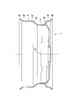
- a shape including a drop 2, wells 3 a and 3 b, a ledge 4, bead sheets 5 a and 5 b, flanges 6 a and 6 b, and the like is employed as in the rim 1 a described with reference to FIG. 12. I can do it.
- the specific contents of the flare step S7 and the roll step S8 are not particularly limited, and a general method can be adopted.
- the flare step S7 is a step of expanding the peripheral edge of the rim material by pressing a forming tool against the peripheral edge of the cylindrical rim material.
- the roll step S8 the flared cylindrical rim material is rolled while being sandwiched between a pair of rolls on which predetermined irregularities are formed, and formed into the rim shape.
- the roll process S8 includes, for example, a drop molding process, a flange molding process, and a finish molding process. *
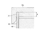
- the thickening step S6 includes a heating step in which a heating region 22 in which the deformation resistance is lowered by heating in advance is formed in the peripheral portion 21 of the rim material 20; after this heating step, for example, FIG. 2 and FIG. And a pressing step of increasing the thickness of the heating region 22 by performing pressing using the mold 10 (10a, 10b) shown in FIG.
- the heating step is performed as a pretreatment of the pressing step. First, the pressing step, which is the basis of the thickening step S6, is described first, and then the heating step is continued. And
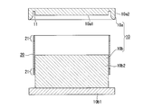
- the mold 10 includes a pair of a press mold 10 a having an annular groove 11 and a support mold 10 b that supports the inner peripheral surface of the rim material 20.
- the pressing mold 10a is a disk-shaped mold having an outer diameter larger than that of the rim material 20, and includes an inner convex circular portion 10a1 formed on the inner side with the annular groove 11 as a boundary, and the annular groove 11
- the outer convex circle part 10a2 formed in the outer side is provided.
- the annular groove 11 is formed by the outer peripheral surface of the inner convex circular portion 10a1, the inner peripheral surface of the outer convex circular portion 10a2, and the outer peripheral surface facing each other and the bottom surface formed on the back side of the inner peripheral surface.
- a compartment is formed.
- the support mold 10b includes a disk-shaped base portion 10b1 and a columnar portion 10b2 formed integrally on the base portion 10b1 so as to be coaxial with the base portion 10b1.
- the outer diameter dimension of the cylindrical portion 10b2 is close to the inner diameter dimension of the inner peripheral surface of the rim material 20 in order to support the inner peripheral surface of the rim material 20 from the inner side, and the rim material 20 is externally fitted. It has been established to ensure the necessary clearance. Further, the height of the cylindrical portion 10b2 is lower than the height of the rim material 20 in the axial direction. This is for the purpose of increasing the thickness of the rim material 20, and details thereof will be described later.
- the pressing die 10 a is lowered from above the rim material 20 so that the peripheral edge 21 of the rim material 20 and the annular groove 11 are coaxial, and the peripheral edge 21 is accommodated coaxially in the annular groove 11. .
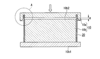
- the peripheral edge portion 21 of the rim material 20 reaches the bottom surface of the annular groove 11, it becomes as shown in FIG. 3, and in this state, the cylindrical portion 10b2, the rim material 20, and the annular groove 11 are coaxial with each other.
- a predetermined gap g is provided between the lower surface of the inner convex circular portion 10a1 of the pressing mold 10a and the upper surface of the cylindrical portion 10b2 of the supporting mold 10b. This gap g becomes a compression processing allowance.
- the peripheral edge 21 of the rim material 20 is further lowered from the state shown in FIG. 3 in which the peripheral edge portion 21 of the rim material 20 is accommodated in the annular groove 11 toward the rim material 20.
- a compressive load is applied to the portion 21 in the axial direction (the direction of the white arrow in FIG. 3), and the thickness of the peripheral portion 21 is increased so that the heating region 22 fills the annular groove 11.
- the compression process is finished when the gap g becomes zero.
- Step S6 is completed.
- the flare process S7, the roll process S8, and the expander process S9 are performed on the rim material 20 after the thickening process S6.
- the vehicle wheel rim is completed by welding and fixing the disk in the rim thus processed (step S10 in FIG. 1).
- the support mold 10b is a mold whose main purpose is to prevent the rim material 20 from being bent. For this reason, there may be almost no gap between the inner circumferential surface of the rim material 20 and the outer circumferential surface of the cylindrical portion 10b2, but if this gap is too narrow, it will be difficult to insert and remove the rim material 20, so a certain gap It is preferable that there is.
- the dimensional difference between the inner diameter of the rim material 20 and the outer diameter of the cylindrical portion 10b2 is preferably 1.0 to 3.0 mm. In this case, the gap is approximately half of the above dimensional difference, and is 0.5 to 1.5 mm.
- die 10b which supports the internal peripheral surface of the rim
- a support mold (not shown) that covers and supports the outer peripheral surface, or a support mold (not shown) that supports both the inner and outer peripheral surfaces of the rim material 20 may be adopted.
- the thickening process S6 in this embodiment was performed with respect to one of a pair of peripheral parts 21 in the cylindrical rim material 20, you may perform it with respect to both.
- the thickening step S6 is performed before the rim shape processing (before the roll step S8).
- the present invention is not limited to this, and the thickening step is performed after the rim shape processing is performed first. It is also possible to perform step S6. Further, the thickening step S6 may be divided into two times and performed once before and after the rim shape processing.
- the manufacturing method of the wheel rim for automobiles according to the present embodiment includes a molding step (rolling step S8) for molding the cylindrical rim material 20 into a rim shape; and at least one of the rim materials 20 before and after the molding step. And a thickening step S6 for increasing the thickness of the peripheral edge 21. And in thickness increasing process S6, in the state which inserted the peripheral part 21 which provided the heating area
- the thickened portion is formed by applying a compressive load in the axial direction of the rim material 20 to the peripheral portion 21.
- the peripheral part 21 of the rim material 20 is increased in a short time compared with the thickening process performed by the spinning machine. Can do. For this reason, it is possible to perform processing within the cycle times of steps S1 to S5 and S7 to S9 before and after the thickening step S6, and the production efficiency is not lowered. That is, when processing a plurality of rim materials 20 in order, while processing each of the processes S1 to S9 shown in FIG. 1, a process that requires the longest working time among these processes S1 to S9 (for example, a roll process) S8) determines the number of products produced per unit time, that is, the production efficiency.
- the thickening step S6 When the thickening step S6 is viewed from such a viewpoint, if the thickening step S6 can finish the processing in a shorter time than the roll step S8, the production efficiency is not lowered. Moreover, since a relatively simple press apparatus is used without using an expensive apparatus such as a spinning machine, there is little increase in manufacturing cost associated with the thickening process.
- the pressing step that forms the basis of the thickening step S6.
- the pressing step of the rim material 20 in order to selectively increase only the peripheral portion 21, the deformation resistance of the peripheral portion 21 is reduced. It is necessary to lower it in advance.
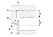
- the pretreatment for that is the heating step, and the details thereof will be described below in connection with the contents of the pressing step. That is, in the method for manufacturing a wheel rim for an automobile according to the present embodiment, when performing the thickening step S6, as shown in FIG. A lowered heating region 22 is formed. Thereafter, as shown in FIG.
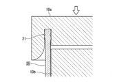
- the peripheral edge 21 including the heating region 22 is accommodated in the annular groove 11, and in that state, a compressive load is applied in the axial direction of the rim material 20 (the direction of the white arrow) As shown in FIGS. 4C and 4D, it is easier to increase the thickness by selecting only the peripheral edge 21 of the rim material 20.
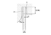
- the heating width (Wh) of the heating region 22 in the peripheral portion 21 is preferably equal to or greater than the planned increase in thickness (W) of the thickened portion formed in the peripheral portion 21 of the rim material 20.
- the heating width (Wh) means the length of the heating region 22 in the peripheral edge portion 21, and the heating region 22 means, for example, a region of 450 ° C. or higher.
- the heating temperature of the peripheral portion 21 is preferably set to a temperature range in which the deformation resistance (strength) of the rim material 20 can be sufficiently lowered to easily increase the thickness, while sufficient strength can be recovered after cooling.
- limiting in particular in a heating method Well-known methods, such as induction heating and radiation heating, are employable. Among various heating methods, induction heating is particularly preferable because of its high heating efficiency and easy installation of the apparatus.
- region 22 which is heated and has reached the temperature range mentioned later among the peripheral parts 21 is a part shown to the heating width Wh.
- the heating region 22 is provided with a gap t1 between the peripheral portion 21 and the annular groove 11 on the inner peripheral surface side of the peripheral edge portion 21 and before the compressive load is received.
- 11 is provided with a gap t2.
- the total dimension of t1 + t2 + t3 will become substantially equal to the thickness dimension of the peripheral part 21 calculated
- the heating region 22 shown in FIG. 5 receives a compressive load toward the lower side of the drawing sheet due to the annular groove 11, its length dimension gradually decreases. Along with this compressive deformation, the thickness dimension of the heating region 22 is uniformly increased at each position in the vertical direction, and finally the inside of the annular groove 11 is filled. As a result, the heating region 22 is increased in thickness evenly at any position in the axial direction of the annular groove 11.
- region 22 after the yield stress at the time of the heating of the rim
- the heating temperature of the heating region 22 assumed as a steel material used for the rim is preferably in the range of 450 to 850 ° C.
- FIG. 6 shows an example in which a high-tensile steel plate having a yield stress of 800 N / mm 2 is heated, and the yield stress after heating and after cooling is measured.
- the heating temperature is 450 ° C.
- the yield stress cannot be reduced to 400 N / mm 2 or less (less than half of the original yield stress), and the deformation resistance is not sufficiently lowered.
- the heating temperature is 450 ° C. or higher
- the yield stress can be lowered to 400 N / mm 2 or less by heating, and the yield stress after cooling can be recovered to a value close to the original yield stress.
- the heating temperature is 450 ° C. to 850 ° C. in the case of high-tensile steel, although it varies depending on the material of the rim material 20. It is preferable. Furthermore, 500 ° C. to 750 ° C. is more preferable in this temperature range.
- the depth of the annular groove 11 (symbol D in FIG. 4A) is preferably equal to or greater than the heating width Wh of the peripheral edge 21 (see FIGS. 4A and 5). If this is not satisfied, the peripheral edge 21 may buckle and adversely affect the dimensional accuracy of the final product.
- At least one peripheral portion 21 of the cylindrical rim material 20 is thickened.
- at least the outer peripheral portion when used as a wheel rim for an automobile, at least the outer peripheral portion. It is preferable to increase the thickness relative to the peripheral edge. This is because the outer peripheral edge of the automobile wheel rim is required to have high strength at the time of collision with the curb. If the impact strength of this part can be increased, the other parts can be thinned, which contributes to the weight reduction of the entire automobile wheel. As a result, it is possible to reduce the vehicle weight of an automobile equipped with a plurality of automobile wheels, thereby improving fuel efficiency and further taking measures against environmental pollution.
- the present embodiment can be applied to the manufacture of automobile wheel rims of various materials, it is particularly suitable for the manufacture of steel wheel rims. Above all, it is most suitable for manufacturing high-strength steel wheel rims.
- the thickening step S6 includes the heating step of heating the peripheral portion 21. That is, after the peripheral edge portion 21 is heated, it is inserted into the annular groove 11 to apply a compressive load. Then, in the axial direction of the rim material 20, when the width dimension of the heating region 22 of the peripheral edge 21 before applying the compressive load is Wh, and the width dimension of the thickened portion after applying the compressive load is W In addition, Wh> W. Further, when the depth dimension of the annular groove 11 in the axial direction of the rim material 20 is D and the width dimension of the heating region 22 of the peripheral edge 21 before applying the compressive load is Wh, D> Wh. Yes.
- the heating temperature of the peripheral portion 21 is in the range of 450 ° C. to 850 ° C.
- the thickened portion is formed on at least the outer opening edge that faces outward when both the peripheral portions 21 of the rim material 20 are mounted on an automobile.
- the heating temperature in the heating region 22 is given a temperature gradient in the vertical direction of the drawing (the axial direction of the rim material 20) in FIG. That is, in the heating region 22, the temperature gradient is such that the temperature is highest at the opening tip edge that contacts the annular groove 11 and receives the compressive load first, and gradually decreases as the distance from the opening tip edge increases. It is turned on and heated.
- the temperature in the heating region 22 preferably satisfies the above-described temperature range of 450 ° C. to 850 ° C. (more preferably 500 ° C. to 750 ° C.) at any location.
- the deformation resistance is such that the deformation resistance (strength) gradually decreases from the position farthest away from the opening tip edge toward the opening tip edge in the heating region 22.
- Distribution intensity distribution
- the increase in deformation of the peripheral edge portion 21 in the thickening step S6 is relatively low in deformation resistance (strength) in the heating region 22 and the opening tip edge.
- the local deformation starts gradually at this point, and this local deformation gradually proceeds toward the back position.
- the increase in thickness is completed in all the heating regions 22. In this way, by causing the thickening deformation in the heating region 22 during the thickening process to be always limited to the position of the processing tip edge, buckling deformation at the peripheral edge portion 21 is prevented, and wrinkles are generated. Can be reliably prevented.
- the manufacturing object is an automobile wheel rim, but the manufacturing object of the present invention is not limited to the automobile wheel rim.
- the present invention can be applied to a method for manufacturing a wheel rim for a truck or an agricultural machine.
- the material of the automobile wheel rim was high-tensile steel, but the invention is not limited thereto, and the automobile wheel rim may be manufactured using a material made of an aluminum-magnesium alloy. .
- the peripheral edge 21 is heated before being inserted into the annular groove 11 in the thickening step S6, and thereafter, the peripheral edge 21 is thickened by compression.
- heating and thickening by compression processing may be performed simultaneously. 4A to 4D described in the thickening step S6, the peripheral portion 21 is not heated at the stage of FIG. 4A before the peripheral portion 21 is inserted into the annular groove 11, and the peripheral portion 21 is not heated.
- FIG. 4B in which is inserted into the annular groove 11
- heating of the peripheral portion 21 is started.
- the compression process shown in FIGS. 4C to 4D is simultaneously performed while continuing to heat the peripheral edge 21 as it is.
- the press die 10a in addition to heating by induction heating, the press die 10a itself is heated, and the peripheral portion 21 is moved by heat transfer by contact between the press die 10a and the peripheral portion 21.
- a method of heating from the opening edge can also be adopted.
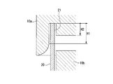
- the annular groove 11 is provided on the pressing mold 10a and is coaxial with each other, and an inner wall surface and an outer annular wall surface, and a bottom wall surface connecting the inner wall surface and the outer wall surface.
- H1 H1 when the height dimension of the outer wall surface from the bottom wall surface in the axial direction of the rim material 20 is H1, and the height dimension of the inner wall surface from the bottom wall surface is H2.
- H2 H2 when the height dimension of the outer wall surface from the bottom wall surface in the axial direction of the rim material 20 is H1, and the height dimension of the inner wall surface from the bottom wall surface is H2.
- the deformation resistance is locally reduced by performing the heating step, but means other than heating may be adopted as long as the deformation resistance can be lowered. However, among various means, it can be said that heating is most excellent from the viewpoint of applicability and the like. Furthermore, the deformation resistance may be locally reduced in advance by applying a process such as annealing to a portion that becomes the peripheral portion 21 in a state of a steel strip or a flat plate separated from the steel strip.
- the peripheral portion was preheated to 700 ° C., and then performed using the pressing die 10a and the supporting die 10b shown in FIGS. 4A to 4D.
- Two types of heating width Wh were prepared, one for 20 mm and one for 28 mm.
- the depth of the annular groove 11 of the pressing die 10a was 30 mm.
- a cylindrical rim material that does not partially increase the peripheral edge portion was prepared, and similarly, after flaring, it was formed into a rim shape by a roll process.
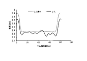
- FIG. 9 in an embodiment using a rim material having a thickness of 2.36 mm and a peripheral edge portion increased to 2.60 mm, in a state after forming the rim shape, other than the rim peripheral edge portion.
- the part was the same as that of the comparative example shown in FIG. 7, but the thickness of the rim peripheral part could be increased to 2.43 mm.
- the rim peripheral portion is in a state after forming the rim shape.
- the other parts were the same as in the comparative example shown in FIG. 7, but the thickness of the rim peripheral part could be increased to 2.71 mm.
- the portions other than the peripheral edge portion of the rim are 1.91 mm-2. While it was in the range of 06 mm, the thickness of the peripheral edge of the rim could be increased to 2.46 mm.
- the present invention it is possible to increase the thickness of the portion corresponding to the opening edge (periphery portion) of a wheel rim such as an automobile wheel rim without lowering the production efficiency and with good dimensional accuracy. For this reason, even if the opening edge (peripheral portion) of the rim material is thinned with the weight reduction of the wheel rim, the opening edge can be thickened to obtain sufficient strength.
- the present invention is particularly useful for manufacturing a wheel rim for automobiles using high-strength steel.
Landscapes
- Engineering & Computer Science (AREA)
- Mechanical Engineering (AREA)
- Forging (AREA)
Abstract
Description
(1)本発明の一態様におけるホイールリムの製造方法は、円筒状のリム素材をリム形状に成形加工する成形工程と;前記成形工程前後の少なくとも一方において前記リム素材の少なくとも一方の開口端縁の板厚を増す増肉工程と;を備え、前記増肉工程で、前記開口端縁の板厚よりも幅広の環状溝を持つ金型の前記環状溝内に前記開口端縁を挿入した状態で、前記開口端縁に対して前記リム素材の軸線方向の圧縮荷重をかけて増肉部を形成する。
また、上記(8)に記載のホイールリムの製造方法の場合、開口端縁の座屈発生をより確実に防ぎながら増肉加工を行うことが可能となる。
また、上記(9)及び(10)に記載の自動車用ホイールリムの製造方法によれば、上記(1)に記載のホイールリムの製造方法と同様の効果を得ることが可能である。
自動車用ホイールリムの製造に際しては、まず、平板から円筒状のリム素材を得る必要があるが、その方法については一般的な方法を採用すればよい。例えば図1のフローチャートに示すように、コイル状に巻かれた鋼帯をアンコイルしてローラで矯正する工程S1と、矯正した鋼帯を所定の寸法に切断して平板を得る工程S2と、得た平板を円筒状に曲げる曲げ工程S3と、曲げた平板の両端縁を互いに突き合わせて溶接する突合溶接工程S4と、溶接部分のバリなどを除去する仕上げ工程S5とにより、円筒状のリム素材を得ることができる。
このようにして得たリム素材より自動車用ホイールリムを製造する方法の各実施形態を、以下に続けて説明する。
本発明の第1実施形態に係る自動車用ホイールリムの製造方法において、前記円筒状のリム素材には、その一対の開口端縁(以下、「周縁部」と言う場合もある。図2に符合21で示す一対の環状部分である)のうちの少なくとも一方を増肉する増肉工程S6と、リム素材の両開口端縁を拡径するフレア工程S7と、リム素材にリム形状を形成する複数のロール工程S8と、リム径を整えるエキスパンダー工程S9と、が施され、その結果、リムが完成する。
前記リム形状の一例としては、図12で説明した前記リム1aと同様に、ドロップ2、ウエル3a,3b、レッジ4、ビードシート5a,5b、フランジ6a,6bなどを含む形状を採用することが出来る。
前記加熱工程は、前記プレス工程の前処理として行われるものであるが、まずは増肉工程S6の基本であるプレス工程の説明を先に行い、その後に、前記加熱工程の説明を続けて行うものとする。
プレス用金型10aは、リム素材20よりも大きな外径を持つ円盤状の金型であり、前記環状溝11を境としてその内側に形成された内側凸円部10a1と、前記環状溝11の外側に形成された外側凸円部10a2とを備えている。言い換えると、内側凸円部10a1の外周面と、外側凸円部10a2の内周面と、これら互いに対向する外周面及び内周面の奥側に形成された底面とにより、前記環状溝11が区画形成されている。
外側凸円部10a2は、前記環状溝11の底面からの高さ寸法が、内側凸円部10a1の高さ寸法よりも高くなっている。そして、外側凸円部10a2には、環状溝11の前記内周面に滑らかに連続するように、断面視円弧状の面取りが形成されている。この面取りが形成されていることにより、リム素材20をスムーズに環状溝11内に導いて挿入することが可能となっている。
また、円柱部10b2の高さ寸法は、リム素材20の軸方向の高さ寸法よりも低めになっている。これは、リム素材20の増肉加工を行うためであり、その詳細については後述する。
より詳しく言うと、まず図2に示すように、支持金型10bの円柱部10b2にリム素材20を同軸に外嵌めしていく。その結果、図3に示すように、リム素材20の下端である他方の周縁部21が土台部10b1の上面に当接して、リム素材20の軸方向荷重を土台部10b1の上面で支持するとともに、周縁部21が円柱部10b2の上面よりも所定寸法、上方に向かって張り出た状態となるように、リム素材20が配置される。
このようにしてリム素材20の周縁部21が環状溝11内に収容された図3の状態より、プレス用金型10aをリム素材20に向けてさらに下げていくことで、リム素材20の周縁部21に対し、その軸方向(図3中の白抜き矢印の方向)に圧縮荷重が加えられ、周縁部21の内の特に加熱領域22が環状溝11内を満たすように増肉変形していき、前記隙間gがゼロになった時点で圧縮加工が終了する。
その後、プレス用金型10aをリム素材20から取り外し、さらにリム素材20を支持金型10bから取り外すと、リム素材20の周縁部21のみが他所に比べて板厚が厚くなっており、増肉工程S6が完了する。
増肉工程S6後のリム素材20には、前記フレア工程S7、ロール工程S8、エキスパンダー工程S9と、が施される。このようにして加工されたリム内に前記ディスクを溶接固定(図1の工程S10)することで、自動車用ホイールリムの完成となる。
また、本実施形態における増肉加工S6は、円筒状のリム素材20における一対の周縁部21のうちの一方に対して行ったが、両方に対して行ってもよい。なお、一対の周縁部21のうちの一方のみに対して増肉工程S6を行う場合には、この自動車用ホイールリムを自動車に装着した際に外側となる方に行うのが好ましい。
また、本実施形態では、増肉工程S6をリム形状加工よりも前(ロール工程S8よりも前)に行うものとしたが、これのみに限らず、先にリム形状加工を行ってから増肉工程S6を行うことも可能である。さらには、増肉工程S6を2回に分け、リム形状加工の前後に1回ずつ行うようにしてもよい。
本実施形態に係る自動車用ホイールリムの製造方法は、円筒状のリム素材20をリム形状に成形加工する成形工程(ロール工程S8)と;成形工程前後の少なくとも一方においてリム素材20の少なくとも一方の周縁部21の板厚を増す増肉工程S6と;を備える。そして、増肉工程S6で、周縁部21の板厚よりも幅広の環状溝11を持つプレス用金型10aの環状溝11内に、加熱領域22を予め設けた周縁部21を挿入した状態で、周縁部21に対してリム素材20の軸線方向の圧縮荷重をかけて増肉部を形成する。
また、スピニング加工機のような高価な装置を用いず、比較的簡便なプレス装置を用いるため、増肉加工に伴う製造コストの上昇が少ない。
すなわち、本実施形態に係る自動車用ホイールリムの製造方法においては、前記増肉工程S6を行うに際し、図4Aに示すように、リム素材20の周縁部21内に、予め加熱して変形抵抗を下げた加熱領域22を形成しておく。その後、図4Bに示すように、加熱領域22を含む周縁部21を環状溝11内に収容し、その状態でリム素材20の軸方向(白抜き矢印の方向)に圧縮荷重を加えることで、図4C及び図4Dに示すように、リム素材20の周縁部21のみを選択して増肉することがより容易となる。周縁部21における加熱領域22の加熱幅(Wh)は、リム素材20の周縁部21に形成される増肉部の、予定される増肉長さ(W)以上であることが好ましい。
図5において、周縁部21のうち、加熱されて後述の温度範囲に達している加熱領域22が加熱幅Whに示す部分である。そして、この加熱領域22は、圧縮荷重を受ける前の状態において、周縁部21の内周面側では環状溝11との間に隙間t1が設けられ、また周縁部21の外周面側では環状溝11との間に隙間t2が設けられている。そして、加熱領域22の厚み寸法をt3とした場合、t1+t2+t3の合計寸法が、増肉後において求められる周縁部21の厚み寸法に略等しくなる。実際には、冷却後の熱収縮により厚み寸法t3が若干薄くなることを見越して、隙間t1、t2を若干大きめに設定することが好ましい。
なお、増肉の仕方としては、周縁部21の内周面及び外周面の双方が均等に厚くなるように増肉しても良いし、または、内周面及び外周面の何れか一方のみが厚くなるように増肉してもよい。
なお、本実施形態は、様々な材質の自動車用ホイールリムの製造に適用することが可能であるが、特に、鋼製ホイールリムの製造に適している。中でも、高張力鋼製ホイールリムの製造に最適である。
そして、リム素材20の軸線方向における、前記圧縮荷重を加える前における周縁部21の加熱領域22の幅寸法をWhとし、前記圧縮荷重を加えた後における増肉部の幅寸法をWとした場合に、Wh>Wとなっている。
さらに、リム素材20の軸線方向における、環状溝11の深さ寸法をDとし、圧縮荷重を加える前における周縁部21の加熱領域22の幅寸法をWhとした場合に、D>Whとなっている。
さらに、増肉工程S6で、リム素材20の両方の周縁部21のうち、少なくとも、自動車に装備された際に外向きとなる外側開口端縁に対し、前記増肉部を形成している。
本発明の第2実施形態に係る自動車用ホイールリムの製造方法について以下に説明する。本実施形態は、上記第1実施形態の変形例に相当するものであり、上記第1実施形態との相違点を主に説明し、その他については上記第1実施形態と同様であるとして重複説明を省略する。
すなわち、加熱領域22内において、環状溝11に当接して真っ先に圧縮荷重を受ける開口先端縁で最も温度が高く、この開口先端縁より奥に離れるに従って徐々に温度が低くなるような温度勾配をつけて加熱している。ただし、加熱領域22内の温度としては、何れの箇所においても、前述の温度範囲である450℃~850℃(より好ましくは500℃~750℃)を満たすことが好ましい。
このように、増肉加工中の加熱領域22内における増肉変形を、常に前記加工先端縁の位置に限定して行わせることにより、周縁部21における座屈変形を防止して、皺の発生を確実に防ぐことが可能となる。
また、上記各実施形態においては、自動車用ホイールリムの素材が高張力鋼であったが、これのみに限らず、アルミニウム・マグネシウム合金からなる素材を用いて自動車用ホイールリムを製造してもよい。
すなわち、増肉工程S6で説明した図4A~図4Dの各工程のうち、周縁部21を環状溝11内に挿入する前の図4Aの段階では周縁部21の加熱を行わず、周縁部21を環状溝11内に挿入した図4Bの状態で周縁部21の加熱を開始する。そして、そのまま周縁部21の加熱を継続しながら、図4C~図4Dに示す圧縮加工を同時に行う。
なお、この場合の加熱方法としては、誘導加熱による加熱の他、プレス用金型10a自体を加熱して、プレス用金型10aと周縁部21との当接による熱伝達で周縁部21をその開口端縁より加熱する方法も採用可能である。
すなわち、増肉工程S6で、増肉中の周縁部21の内周面を環状溝11の内壁面で支えると共に、周縁部21の外周面を前記内壁よりも幅広の、環状溝11の外壁面で支えながら、圧縮加工を行ってもよい。
また、上記各実施形態では、前記加熱工程を行うことにより局所的に変形抵抗を下げたが、変形抵抗を下げることが出来るのであれば、加熱以外の手段を採用してもよい。しかしながら、各種手段の中でも、適用容易性等の観点により、加熱が最も優れていると言える。
さらには、鋼帯の状態又は鋼帯から切り離した平板の状態で、周縁部21となる部分に焼き鈍し等の加工を加えておくことで、予め、局所的に変形抵抗を下げてもよい。
すなわち、まず、高張力鋼の平板(厚さ2.36mm及び2.00mmの2種、降伏応力は共に800N/mm2)を複数枚用意し、これら平板それぞれを、円筒状に曲げて両端縁を突き合わせ溶接して、2種の円筒状リム素材(それぞれ、外周面の半径が170mmで、円筒の軸線方向に平行な幅寸法が202mm)を得た。
続いて、それぞれの円筒状リム素材の周縁部を増肉し、フレアリングした後、ロール工程によってリム形状に成形した。
また、比較のため、一部、周縁部を増肉しない円筒状リム素材を用意し、これに対しても同様に、フレアリングした後、ロール工程によってリム形状に成形した。
まず、2.36mm等厚のリム素材を用いたが増肉加工を行わなかった比較例では、図8に示すように、作製されたリムの周縁部が2.22mmまで薄くなった。
1a リム
1b ディスク
2 ドロップ
3a,3b ウエル
4 レッジ
5a,5b ビードシート
6a,6b フランジ
10 金型
10a プレス用金型
10b 支持金型
11 環状溝
20 リム素材
21 リム素材の周縁部、開口端縁
22 加熱領域
Claims (10)
- 円筒状のリム素材をリム形状に成形加工する成形工程と;
前記成形工程前後の少なくとも一方において前記リム素材の少なくとも一方の開口端縁の板厚を増す増肉工程と;
を備え、
前記増肉工程で、前記開口端縁の板厚よりも幅広の環状溝を持つ金型の前記環状溝内に前記開口端縁を挿入した状態で、前記開口端縁に対して前記リム素材の軸線方向の圧縮荷重をかけて増肉部を形成する
ことを特徴とするホイールリムの製造方法。 - 前記増肉工程が、前記開口端縁を加熱する工程を含むことを特徴とする請求項1に記載のホイールリムの製造方法。
- 前記開口端縁を前記加熱した後に、前記環状溝内に挿入して前記圧縮荷重を加えることを特徴とする請求項2に記載のホイールリムの製造方法。
- 前記開口端縁を前記環状溝内に挿入した状態で前記加熱しながら、前記圧縮荷重を加えることを特徴とする請求項2に記載のホイールリムの製造方法。
- 前記軸線方向の、前記圧縮荷重を加える前における前記開口端縁の加熱領域の幅寸法をWhとし、前記圧縮荷重を加えた後における前記増肉部の幅寸法をWとした場合に、Wh>Wである
ことを特徴とする請求項2~4の何れか一項に記載のホイールリムの製造方法。 - 前記軸線方向の、前記環状溝の深さ寸法をDとし、前記圧縮荷重を加える前における前記開口端縁の加熱領域の幅寸法をWhとした場合に、D>Whである
ことを特徴とする請求項2~5の何れか一項に記載のホイールリムの製造方法。 - 前記開口端縁の加熱温度が、450℃~850℃の範囲内であることを特徴とする請求項2~6の何れか一項に記載のホイールリムの製造方法。
- 前記増肉工程で、増肉中の前記開口端縁の内周面を前記環状溝の内壁で支えると共に、前記開口端縁の外周面を前記内壁よりも幅広の、前記環状溝の外壁で支えながら、前記圧縮荷重を加えることを特徴とする請求項1~7の何れかに記載のホイールリムの製造方法。
- 請求項1~8の何れか一項に記載のホイールリムの製造方法により得られた前記ホイールリム内にディスクを固定する工程を備えることを特徴とする自動車用ホイールの製造方法 。
- 前記増肉工程で、前記リム素材の両方の前記開口端縁のうち、少なくとも、自動車に装備された際に外向きとなる方に対し、前記増肉部を形成することを特徴とする請求項9に記載の自動車用ホイールの製造方法。
Priority Applications (5)
| Application Number | Priority Date | Filing Date | Title |
|---|---|---|---|
| JP2016507831A JP6304370B2 (ja) | 2014-03-14 | 2015-03-12 | ホイールリムの製造方法及び自動車用ホイールリムの製造方法 |
| MX2016011780A MX380227B (es) | 2014-03-14 | 2015-03-12 | Método de producción de llanta de rueda y método de producción de llanta de rueda de vehículo. |
| US15/111,548 US10661328B2 (en) | 2014-03-14 | 2015-03-12 | Production method of wheel rim, and production method of vehicle wheel rim |
| KR1020167024760A KR101927597B1 (ko) | 2014-03-14 | 2015-03-12 | 휠 림의 제조 방법 및 자동차용 휠 림의 제조 방법 |
| CN201580012172.3A CN106102953B (zh) | 2014-03-14 | 2015-03-12 | 车轮轮辋的制造方法以及汽车用车轮轮辋的制造方法 |
Applications Claiming Priority (2)
| Application Number | Priority Date | Filing Date | Title |
|---|---|---|---|
| JP2014-051431 | 2014-03-14 | ||
| JP2014051431 | 2014-03-14 |
Publications (1)
| Publication Number | Publication Date |
|---|---|
| WO2015137463A1 true WO2015137463A1 (ja) | 2015-09-17 |
Family
ID=54071900
Family Applications (1)
| Application Number | Title | Priority Date | Filing Date |
|---|---|---|---|
| PCT/JP2015/057362 Ceased WO2015137463A1 (ja) | 2014-03-14 | 2015-03-12 | ホイールリムの製造方法及び自動車用ホイールリムの製造方法 |
Country Status (6)
| Country | Link |
|---|---|
| US (1) | US10661328B2 (ja) |
| JP (2) | JP6304370B2 (ja) |
| KR (1) | KR101927597B1 (ja) |
| CN (1) | CN106102953B (ja) |
| MX (1) | MX380227B (ja) |
| WO (1) | WO2015137463A1 (ja) |
Cited By (1)
| Publication number | Priority date | Publication date | Assignee | Title |
|---|---|---|---|---|
| US11975566B2 (en) | 2017-08-08 | 2024-05-07 | Vision Composite Products, Llc | Two piece wheel |
Families Citing this family (3)
| Publication number | Priority date | Publication date | Assignee | Title |
|---|---|---|---|---|
| CN107052720B (zh) * | 2017-04-12 | 2019-11-08 | 浙江金固股份有限公司 | 一种钢制车轮的制造方法及其采用该方法成型的车轮 |
| USD962838S1 (en) * | 2019-12-17 | 2022-09-06 | Lawrence Leonard Jetson | Automotive wheel rim |
| CN113319541B (zh) * | 2021-07-09 | 2023-05-09 | 重庆市超群工业股份有限公司 | 汽车轮毂加工工艺 |
Citations (5)
| Publication number | Priority date | Publication date | Assignee | Title |
|---|---|---|---|---|
| WO1996025257A1 (en) * | 1995-02-13 | 1996-08-22 | Hess Engineering, Inc. | Method of forming vehicle wheel rims |
| JPH11333537A (ja) * | 1998-05-27 | 1999-12-07 | Dai Ichi High Frequency Co Ltd | スラリー輸送用鋼管及びその製造方法 |
| JP2005349455A (ja) * | 2004-06-14 | 2005-12-22 | Work:Kk | ホイールの製造方法 |
| US20090189391A1 (en) * | 2007-11-15 | 2009-07-30 | William Joseph Ferlin | Reinforced bead tube design |
| WO2011125968A1 (ja) * | 2010-04-06 | 2011-10-13 | トピー工業株式会社 | 車両用ホイールリムの製造方法 |
Family Cites Families (17)
| Publication number | Priority date | Publication date | Assignee | Title |
|---|---|---|---|---|
| GB550186A (en) * | 1941-02-17 | 1942-12-28 | Thompson Prod Inc | Improvements in or relating to methods of forming flanges at the ends of tubing |
| US4050135A (en) * | 1975-07-11 | 1977-09-27 | Grotnes Machine Works, Inc. | Flat base truck rim forming system |
| DE2545935C2 (de) * | 1975-10-14 | 1984-04-26 | Mannesmann AG, 4000 Düsseldorf | Verfahren und Walzwerk zum Auswalzen einer Bramme, vorzugsweise einer Stranggußbramme, zu einem Knüppel mit quadratischem oder annähernd quadratischem Querschnitt |
| US4049184A (en) * | 1976-06-07 | 1977-09-20 | Jury Iosifovich Rozengart | Method of manufacturing polymetallic pipes |
| JPS5510385A (en) | 1978-07-11 | 1980-01-24 | Hayashi Lacing:Kk | Manufacture of flanged rim made of light alloy metal for automobile |
| DE2843728A1 (de) | 1978-10-06 | 1980-04-24 | Wheels India | Verfahren und vorrichtung zur herstellung von felgen und nach dem verfahren hergestellte felge |
| US4842818A (en) * | 1980-03-17 | 1989-06-27 | Daido Tokushuko Kabushiki Kaisha | Method for manufacturing tapered rods |
| JPS59109404A (ja) | 1982-12-14 | 1984-06-25 | Nissan Motor Co Ltd | 自動車用ロ−ドホイ−ルリム |
| JPS6224834A (ja) | 1985-07-26 | 1987-02-02 | Isuzu Motors Ltd | 金属軸と金属スリ−ブとの結合方法 |
| JP3390838B2 (ja) | 1992-12-18 | 2003-03-31 | 株式会社アローエンタープライズ | 自動車用ホイールの成形方法 |
| US20040205966A1 (en) * | 2001-08-03 | 2004-10-21 | Shinjiroh Ohishi | Method of manufacturing turbine frame of vgs type turbo charger, turbine frame manufactured by the method, exhaust gas guide assembly of vgs type turbo charger using the turbine frame and vgs type turbo charger incorporating the exhaust gas guide assembly |
| US7360387B2 (en) * | 2005-01-31 | 2008-04-22 | Showa Denko K.K. | Upsetting method and upsetting apparatus |
| BRPI0604498A (pt) * | 2006-10-30 | 2008-06-17 | Maxion Sist S Automotivos Ltda | processo de fabricação de aro de roda sem cámara de veìculos fora de estrada, aro obtido pelo processo e roda de um veìculo fora de estrada |
| CN200984931Y (zh) | 2006-12-08 | 2007-12-05 | 长春一汽四环汽车股份有限公司车轮分公司 | 加强型轮辋 |
| CN101468370B (zh) | 2007-12-28 | 2012-03-07 | 比亚迪股份有限公司 | 一种非晶合金热压成形装置及工艺 |
| GB2503936B (en) * | 2012-07-13 | 2020-03-04 | Gkn Wheels Ltd | Manufacture of wheels |
| JP6082967B2 (ja) * | 2012-12-27 | 2017-02-22 | 株式会社小松製作所 | プラズマ切断機および切断方法 |
-
2015
- 2015-03-12 MX MX2016011780A patent/MX380227B/es unknown
- 2015-03-12 US US15/111,548 patent/US10661328B2/en active Active
- 2015-03-12 CN CN201580012172.3A patent/CN106102953B/zh active Active
- 2015-03-12 KR KR1020167024760A patent/KR101927597B1/ko active Active
- 2015-03-12 JP JP2016507831A patent/JP6304370B2/ja active Active
- 2015-03-12 WO PCT/JP2015/057362 patent/WO2015137463A1/ja not_active Ceased
-
2017
- 2017-12-26 JP JP2017250240A patent/JP2018051631A/ja active Pending
Patent Citations (5)
| Publication number | Priority date | Publication date | Assignee | Title |
|---|---|---|---|---|
| WO1996025257A1 (en) * | 1995-02-13 | 1996-08-22 | Hess Engineering, Inc. | Method of forming vehicle wheel rims |
| JPH11333537A (ja) * | 1998-05-27 | 1999-12-07 | Dai Ichi High Frequency Co Ltd | スラリー輸送用鋼管及びその製造方法 |
| JP2005349455A (ja) * | 2004-06-14 | 2005-12-22 | Work:Kk | ホイールの製造方法 |
| US20090189391A1 (en) * | 2007-11-15 | 2009-07-30 | William Joseph Ferlin | Reinforced bead tube design |
| WO2011125968A1 (ja) * | 2010-04-06 | 2011-10-13 | トピー工業株式会社 | 車両用ホイールリムの製造方法 |
Cited By (1)
| Publication number | Priority date | Publication date | Assignee | Title |
|---|---|---|---|---|
| US11975566B2 (en) | 2017-08-08 | 2024-05-07 | Vision Composite Products, Llc | Two piece wheel |
Also Published As
| Publication number | Publication date |
|---|---|
| KR20160119829A (ko) | 2016-10-14 |
| US20160332210A1 (en) | 2016-11-17 |
| CN106102953B (zh) | 2019-06-07 |
| JP2018051631A (ja) | 2018-04-05 |
| JP6304370B2 (ja) | 2018-04-04 |
| CN106102953A (zh) | 2016-11-09 |
| MX380227B (es) | 2025-03-04 |
| KR101927597B1 (ko) | 2018-12-10 |
| US10661328B2 (en) | 2020-05-26 |
| JPWO2015137463A1 (ja) | 2017-04-06 |
| MX2016011780A (es) | 2016-10-28 |
Similar Documents
| Publication | Publication Date | Title |
|---|---|---|
| CN102215997B (zh) | 筒状部件的制造方法 | |
| US9452459B2 (en) | Method for manufacturing shaped steel the cross-sectional shape of which changes in the longitudinal direction, and roll forming device | |
| JP2018051631A (ja) | ホイールリムの製造方法及び自動車用ホイールリムの製造方法 | |
| KR101419313B1 (ko) | 차량용 휠림의 제조 방법 | |
| JP2010149182A5 (ja) | ||
| CN108463296B (zh) | 旋压装置以及旋压方法 | |
| US9878360B2 (en) | Method of producing shaped steel changing in cross-sectional shape in longitudinal direction and roll forming apparatus for same | |
| KR101940165B1 (ko) | 프레스 성형 방법 및 프레스 성형 부품의 제조 방법 | |
| EP3003596B1 (en) | Method of manufacturing metal core for resin gear | |
| US8516705B2 (en) | Method of manufacturing bearing ring member for rolling bearing unit | |
| US9630279B2 (en) | Method of manufacturing wheel disc | |
| JP2003211901A (ja) | 自動車用ホイールの製造方法 | |
| RU2613248C2 (ru) | Изготовление колес | |
| JP6009266B2 (ja) | 車両用ホイールリムの製造方法 | |
| JP6187213B2 (ja) | 自動車用ホイールリムの製造方法 | |
| KR20190014201A (ko) | 차량용 핫 스탬핑 부품 제조장치 및 제조방법 | |
| JP2003236637A (ja) | 2ピースホイールおよびその製造方法 | |
| CN121715809A (zh) | 一种车轮轮辋制造方法 | |
| SE427333B (sv) | Sett for formning av en felg till fordonshjul fran ett cylindriskt ringformigt emne |
Legal Events
| Date | Code | Title | Description |
|---|---|---|---|
| 121 | Ep: the epo has been informed by wipo that ep was designated in this application |
Ref document number: 15760778 Country of ref document: EP Kind code of ref document: A1 |
|
| ENP | Entry into the national phase |
Ref document number: 2016507831 Country of ref document: JP Kind code of ref document: A |
|
| WWE | Wipo information: entry into national phase |
Ref document number: 15111548 Country of ref document: US |
|
| ENP | Entry into the national phase |
Ref document number: 20167024760 Country of ref document: KR Kind code of ref document: A |
|
| WWE | Wipo information: entry into national phase |
Ref document number: IDP00201606092 Country of ref document: ID |
|
| WWE | Wipo information: entry into national phase |
Ref document number: MX/A/2016/011780 Country of ref document: MX |
|
| NENP | Non-entry into the national phase |
Ref country code: DE |
|
| 122 | Ep: pct application non-entry in european phase |
Ref document number: 15760778 Country of ref document: EP Kind code of ref document: A1 |