WO2015137214A1 - 灯具 - Google Patents
灯具 Download PDFInfo
- Publication number
- WO2015137214A1 WO2015137214A1 PCT/JP2015/056385 JP2015056385W WO2015137214A1 WO 2015137214 A1 WO2015137214 A1 WO 2015137214A1 JP 2015056385 W JP2015056385 W JP 2015056385W WO 2015137214 A1 WO2015137214 A1 WO 2015137214A1
- Authority
- WO
- WIPO (PCT)
- Prior art keywords
- light
- lens
- incident
- lamp
- light source
- Prior art date
- Legal status (The legal status is an assumption and is not a legal conclusion. Google has not performed a legal analysis and makes no representation as to the accuracy of the status listed.)
- Ceased
Links
Images





Classifications
-
- F—MECHANICAL ENGINEERING; LIGHTING; HEATING; WEAPONS; BLASTING
- F21—LIGHTING
- F21S—NON-PORTABLE LIGHTING DEVICES; SYSTEMS THEREOF; VEHICLE LIGHTING DEVICES SPECIALLY ADAPTED FOR VEHICLE EXTERIORS
- F21S43/00—Signalling devices specially adapted for vehicle exteriors, e.g. brake lamps, direction indicator lights or reversing lights
- F21S43/30—Signalling devices specially adapted for vehicle exteriors, e.g. brake lamps, direction indicator lights or reversing lights characterised by reflectors
- F21S43/31—Optical layout thereof
- F21S43/315—Optical layout thereof using total internal reflection
-
- F—MECHANICAL ENGINEERING; LIGHTING; HEATING; WEAPONS; BLASTING
- F21—LIGHTING
- F21S—NON-PORTABLE LIGHTING DEVICES; SYSTEMS THEREOF; VEHICLE LIGHTING DEVICES SPECIALLY ADAPTED FOR VEHICLE EXTERIORS
- F21S43/00—Signalling devices specially adapted for vehicle exteriors, e.g. brake lamps, direction indicator lights or reversing lights
- F21S43/10—Signalling devices specially adapted for vehicle exteriors, e.g. brake lamps, direction indicator lights or reversing lights characterised by the light source
- F21S43/13—Signalling devices specially adapted for vehicle exteriors, e.g. brake lamps, direction indicator lights or reversing lights characterised by the light source characterised by the type of light source
- F21S43/14—Light emitting diodes [LED]
- F21S43/145—Surface emitters, e.g. organic light emitting diodes [OLED]
-
- F—MECHANICAL ENGINEERING; LIGHTING; HEATING; WEAPONS; BLASTING
- F21—LIGHTING
- F21S—NON-PORTABLE LIGHTING DEVICES; SYSTEMS THEREOF; VEHICLE LIGHTING DEVICES SPECIALLY ADAPTED FOR VEHICLE EXTERIORS
- F21S43/00—Signalling devices specially adapted for vehicle exteriors, e.g. brake lamps, direction indicator lights or reversing lights
- F21S43/20—Signalling devices specially adapted for vehicle exteriors, e.g. brake lamps, direction indicator lights or reversing lights characterised by refractors, transparent cover plates, light guides or filters
- F21S43/26—Refractors, transparent cover plates, light guides or filters not provided in groups F21S43/235 - F21S43/255
Definitions
- the present invention relates to a lamp that uses a plurality of lenses having three or more optical surfaces that are non-parallel to each other to represent a depth-like appearance such as a light tunnel.
- the lamp 51 shown in FIG. 9 includes a plurality of LEDs 54 arranged around the convex mirror 52 and a half mirror 55 arranged in front of the convex mirror 52.
- the light from the LED 54 is repeatedly reflected by the half mirror 55 and the convex mirror 52, and the appearance with a sense of depth is obtained by the light transmitted through the half mirror 55.
- Patent Document 1 describes a vehicular beacon lamp that uses an LED and a half mirror in combination and produces a multi-step depth feeling due to the difference in brightness of a plurality of light-emitting lines.
- the conventional lamp 51 it is necessary to use a large number of LEDs 54 as a light source. Further, in order to give a sense of depth, it is necessary to design a long distance between the convex mirror 52 and the half mirror 55, and there is a problem that the thickness of the lamp 51 increases.
- an object of the present invention is to provide a lamp that can realize a thin appearance with a sense of depth.
- a lamp of the present invention includes a light source, a first lens including three or more optical surfaces that are not parallel to each other, and a second lens including three or more optical surfaces that are not parallel to each other.
- the first lens has a first incident surface on which light from the light source is incident, a spectroscopic surface that internally reflects part of the incident light, and transfers at least part of the remaining incident light to the second lens;
- a first emission surface that emits light reflected internally by the surface to the front of the lamp, and the second lens receives a second incidence surface on which light transferred from the first lens is incident, and at least part of the incident light. It includes an inner surface reflecting surface that reflects the inner surface and a second emitting surface that emits the light reflected on the inner surface by the inner surface to the front of the lamp.
- planar light emitter such as an organic EL or LED can be used as the light source.
- the planar light emitter has an advantage that the light source itself can be made thin.
- a planar light emitter is used as the light source, and the first and second lenses and, if necessary, a larger number of lenses can be arranged along the path of the light emitted from the planar light emitter.
- a reflecting mirror that directs the light that is about to pass through the inner reflection surface of the second lens to the front of the lamp so that the light from the light source can be used effectively.
- a reflecting mirror for example, a reflecting film formed on a lens located at the end of the lens array, a reflector arranged away from the last lens, or the like can be used.
- the first and second lenses may be arranged in a state of being separated from each other, or may be arranged in a state of being connected to each other.
- a light guide part that allows light from the light source to pass through is provided between the first lens and the second lens, and the light guide part is connected to the first emission surface and the second emission surface when the light source is turned on. You may comprise so that a dark part may be formed in between.
- the angle formed between the first incident surface of the first lens and the spectroscopic surface may be different from the angle formed between the second incident surface of the second lens and the inner reflection surface so that the direction of the emitted light can be changed.
- the shape of the lens may be various three-dimensional shapes including three or more optical surfaces that are not parallel to each other, such as a triangular prism, a quadrangular prism, a pentagonal prism, and a hexagonal prism.
- the lamp of the present invention can be used as a vehicular lamp.
- the above-described lamp is mounted on the vehicle body so that the first emission surface of the first lens and the second emission surface of the second lens are included in a curved surface that is curved according to the outer shape of the vehicle body. be able to.
- the lamp of the present invention since a plurality of three-dimensional lenses are combined with the light source and three or more optical surfaces that are not parallel to each other are provided on each lens, it is possible to realize a thin and deep appearance.
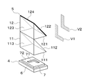
- a vehicle lamp 1 shown in FIG. 1 includes an outer lens 3 on the front surface of a housing 2 and a light source 4 and an inner lens 5 on the inner side of the housing 2.
- the light source 4 includes a light source base 6 below the inner lens 5, and a planar light emitter 7 made of an organic EL is mounted on the upper surface of the light source base 6.
- the inner lens 5 converts the upward light emitted from the planar light emitter 7 into the horizontal direction, transmits the outer lens 3, and emits it forward of the lamp 1 (front, side or rear of the vehicle).
- the inner lens 5 is configured by combining a plurality of (for example, two) lenses 11 and 12.
- Each of the lenses 11 and 12 is formed in a triangular prism shape having right-angled triangles, and is arranged in two upper and lower stages with the axis line horizontal, and includes three optical surfaces that are not parallel to each other around the horizontal axis line. .
- a first incident surface 111 on which light from the planar light emitter 7 is incident, and a part of the incident light is internally reflected and the rest is transferred to the second lens 12.
- a first emission surface 113 that emits light reflected from the inner surface to the front of the lamp.
- a second incident surface 121 on which the light transferred from the first lens 11 is incident On the optical surface of the second lens 12 located in the upper stage, a second incident surface 121 on which the light transferred from the first lens 11 is incident, an inner surface reflecting surface 122 that reflects the incident light on the inner surface, and light that is reflected on the inner surface. And a second exit surface 123 that exits the lamp forward.
- a reflecting mirror 124 is provided on the inner surface reflecting surface 122 of the second lens 12, and all light incident on the second lens 12 is reflected forward by the inner lens reflecting surface 122 and the reflecting mirror 124.
- the planar light emitter 7 is formed to have substantially the same size as the first incident surface 111 of the first lens 11 and is disposed so as to face the incident surface 111 from below.
- the planar light-emitting body 7 is provided with a light-emitting area 71 that represents a design including a logo and a mark, and a non-light-emitting area 72 that defines the outline of the light-emitting area 71.
- the first and second lenses 11 and 12 are arranged along the path of the light emitted from the planar light emitter 7 so that the emission surfaces 113 and 123 are aligned in the same plane. Then, the light from the light emitting region 71 is reflected by the two-stage lenses 11 and 12 to form the two-stage virtual images V1 and V2 behind the inner lens 5, and these virtual images give a sense of depth like a light tunnel. .
- the planar light emitter 7 is used as the light source 4 and the two lenses 11 and 12 are arranged along the optical path of the planar light emitter 7, a convex mirror or a half mirror can be used. Compared with the conventional lamp used, the whole can be made thin and small.
- the reflecting mirror 124 is provided on the second lens 12, all the light transmitted through the first lens 11 can be reflected without waste, and the front of the lamp can be illuminated brightly.
- the planar light-emitting body 7 can represent various designs by changing the shape of the light-emitting region 71.
- the first and second lenses 11 and 12 can be given directionality according to the application or the mounting location of the vehicular lamp 1.
- the inner lens 5 can be adapted to a horizontally long vehicle lamp by using the lenses 11 and 12 that are long in the horizontal direction.
- the inner lens 5 can be adapted to a vertically long vehicle lamp by using the lenses 11 and 12 that are long in the vertical direction.
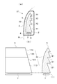
- FIG. 3A the inner lens 5 can be adapted to a horizontally long vehicle lamp by using the lenses 11 and 12 that are long in the horizontal direction.
- the inner lens 5 can be adapted to a vertically long vehicle lamp by using the lenses 11 and 12 that are long in the vertical direction.
- the inner lens 5 can be adapted to a vehicular lamp mounted on the vehicle body corner by using the lenses 11 and 12 extending in the front-rear and left-right directions in the horizontal plane. .
- the planar light-emitting body 7 is used for the light source 4, the whole lamp can be comprised compactly.
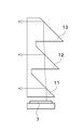
- the inner lens 5 shown in FIG. 4 three lenses 11, 12, and 13 are arranged in a mutually connected state.
- the inner lens 5 is an integral member in which the three lenses 11, 12, and 13 are continuous.
- the first lens 11 and the second lens 12 are connected by a light guide unit 21, and the second lens 12 and the third lens 13 are connected by a light guide unit 22.
- the light guides 21 and 22 function to pass light from the planar light emitter 7, and little light is emitted forward from the light guides 21 and 22.
- a dark part 23 is formed between the first emission surface 113 and the second emission surface 123
- a dark part 24 is formed between the second emission surface 123 and the third emission surface 133.
- a flat portion 25 that allows light to escape is formed at the apex of the third lens 13 so that the upper end of the inner lens 5 does not emit light.
- the inner surfaces of the light guide portions 21 and 22 are flat, but the dark portions 23 and 24 can also be formed when this is a curved surface.
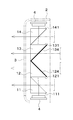
- the four lenses 11, 12, 13, and 14 are connected to the inner lens 5 in the optical axis direction (direction along the light path) of the planar light emitter 7. It is arranged.
- the inner lens 5 is an integral member in which the four lenses 11, 12, 13, and 14 are continuous.
- Each of the lenses 11 to 14 is formed so that the incident surfaces 111, 121, 131, and 141 become narrower as the upper lens is formed, and the exit surfaces 113, 123, 133, and 143 are formed to be included in the common curved surface 32.
- the curved surface 32 is curved according to the outer surface shape of the vehicle body B, and emits light from the planar light-emitting body 7 from the front surface of the inner lens 5 to the periphery of the vehicle body.
- the yield of the planar light-emitting body 7 such as an organic EL becomes worse as the size is increased, and the manufacturing cost increases as the outer shape becomes more complicated.
- the curved surface is disadvantageous in terms of yield and cost than the flat surface.
- the light source 4 has a narrow and small area. The entire front surface of the inner lens 5 can be made to emit light by using the planar light emitter 7.
- the front surface of the inner lens 5 can be easily curved to match the outer shape of the vehicle body B, the surface light emitter 7 having a flat surface is used, and a part of the outer surface of the vehicle body is surface-emitting. It is also possible to realize a novel appearance as if it were.
- the angle ⁇ 1 formed by the first incident surface 111 of the first lens 11 and the spectral surface 112 is larger than the angle ⁇ 2 formed by the second incident surface 121 of the second lens 12 and the inner reflection surface 122. It is set small ( ⁇ 1 ⁇ 2). Further, the angle ⁇ 2 formed by the first incident surface 121 of the second lens 12 and the inner reflective surface 122 is set to be smaller than the angle ⁇ 3 formed by the third incident surface 131 of the third lens 13 and the inner reflective surface 132 ( ⁇ 2 ⁇ 3).
- the direction of light emitted from the plurality of lenses 11, 12, and 13 can be changed according to the mounting position or application of the vehicular lamp. It can be changed arbitrarily.
- the present invention is not limited to the above-described embodiment, and can be implemented by appropriately changing the configuration of each part without departing from the spirit of the invention, as exemplified below.
- A As shown in FIG. 7, the lenses 11, 12, 13 are arranged in a plurality of upper and lower stages at different positions in the front-rear direction.
- B The inner lens 5 shown in FIG. 1 is turned upside down and the light source 4 is installed on the upper part of the housing 2.
- the two light sources 4 are installed above and below the housing 2, the first and second lenses 11 and 12 are arranged so that the incident surfaces 111 and 121 face downward, Arrange the fourth lenses 13 and 14 so that the incident surfaces 131 and 141 face upward.
- the present invention is applied to lamps for various uses such as warning lights, beacon lights, signal lights, street lights, and the like.
Landscapes
- Engineering & Computer Science (AREA)
- General Engineering & Computer Science (AREA)
- Physics & Mathematics (AREA)
- Microelectronics & Electronic Packaging (AREA)
- Optics & Photonics (AREA)
- Non-Portable Lighting Devices Or Systems Thereof (AREA)
Abstract
灯具(1)は、光源(4)の上側に2つのレンズ(11,12)を備える。光源(4)は面状発光体(7)を含み、レンズ(11,12)が三角柱状に形成される。レンズ(11)は、面状発光体(7)から光を入射する入射面(111)、入射光の一部を内面反射し残りをレンズ(12)に転送する分光面(112)、内面反射光を灯具前方へ出射する出射面(113)を含む。レンズ(12)は、レンズ(11)から転送された光を入射する入射面(121)、入射光を内面反射する内面反射面(122)、内面反射光を出射する出射面(123)を備える。
Description
本発明は、互いに非平行な3以上の光学面を備えた複数のレンズを用いて、ライトトンネルのような奥行き感のある見映えを表す灯具に関する。
従来より、光源に複数のLEDを用いて奥行き感を出す灯具が知られている。例えば、図9に示す灯具51は、凸面鏡52の周囲に配列された複数のLED54と、凸面鏡52の前方に配置されたハーフミラー55とを有している。LED54からの光をハーフミラー55と凸面鏡52で繰り返し反射し、ハーフミラー55を透過した光によって奥行き感のある見映えが得られる。
特許文献1には、LEDとハーフミラーを併用し、複数の発光ラインの明暗差によって多段の奥行き感を出す車両用標識灯が記載されている。
ところが、従来の灯具51によると、光源に多数のLED54を使用する必要があった。また、奥行き感を出すためには、凸面鏡52とハーフミラー55との間の距離を長く設計する必要があり、灯具51の厚みが大きくなるという問題点もあった。
そこで、本発明の目的は、薄型でかつ奥行き感のある見映えを実現できる灯具を提供することにある。
上記課題を解決するために、本発明の灯具は、光源と、互いに非平行な3以上の光学面を含む第1レンズと、互いに非平行な3以上の光学面を含む第2レンズとを備え、第1レンズが、光源からの光を入射する第1入射面と、この入射光の一部を内面反射し、入射光の残りの少なくとも一部を第2レンズに転送する分光面と、分光面で内面反射した光を灯具前方へ出射する第1出射面とを含み、第2レンズが、第1レンズから転送された光を入射する第2入射面と、この入射光の少なくとも一部を内面反射する内面反射面と、内面反射面で内面反射した光を灯具前方へ出射する第2出射面とを含むことを特徴とする。
ここで、光源としては、有機EL等の面状発光体またはLEDを使用できる。特に、面状発光体は光源自体を薄く構成できる利点がある。好ましくは、光源に面状発光体を使用し、第1および第2レンズ、必要に応じてより多数のレンズを面状発光体から出射された光の進路に沿って配列することができる。
より好ましくは、光源からの光を有効利用できるように、第2レンズの内面反射面を通過しようとする光を灯具前方へ向かわせる反射鏡を設けることができる。このような反射鏡としては、例えば、レンズ列の最後尾に位置するレンズに形成した反射膜、最後尾のレンズから離して配置したリフレクタなどを使用できる。
第1および第2レンズは、相互に分離された状態で配列してもよく、あるいは、相互に接続された状態で配列してもよい。後者の場合は、第1レンズと第2レンズとの間に、光源からの光を素通りさせる導光部を設け、光源の点灯時に、導光部が第1出射面と第2出射面との間に暗部を形成するように構成してもよい。
また、出射光の向きを変更できるように、第1レンズの第1入射面と分光面のなす角度を、第2レンズの第2入射面と内面反射面のなす角度と相違させてもよい。なお、レンズの形状は、例えば、三角柱、四角柱、五角柱、六角柱など、互いに非平行な3以上の光学面を含む各種の立体形状とすることができる。
さらに、好ましくは、本発明の灯具を車両用灯具として使用することができる。具体的には、上記の灯具を車体上に装備し、第1レンズの第1出射面および第2レンズの第2出射面が車体の外形状に応じて湾曲する曲面に含まれるように構成することができる。
本発明の灯具によれば、光源に複数の立体形レンズを組み合わせ、それぞれのレンズに互いに非平行な3以上の光学面を設けたので、薄型でかつ奥行き感のある見映えを実現できる。
以下、本発明を車両用灯具に具体化した幾つかの実施形態を図面に基づいて説明する。図1に示す車両用灯具1は、ハウジング2の前面にアウターレンズ3を備え、ハウジング2の内側に光源4とインナーレンズ5とを装備している。光源4は、インナーレンズ5の下側に光源ベース6を備え、光源ベース6の上面に、有機ELからなる面状発光体7が装着されている。インナーレンズ5が、面状発光体7が出射した上向きの光を水平方向に変換し、アウターレンズ3を透過させて、灯具1の前方(車両の前方、側方または後方)に出射する。
インナーレンズ5は、複数(例えば2つ)のレンズ11,12を組み合わせて構成されている。レンズ11,12は、それぞれ、端面が直角三角形の三角柱状に形成され、軸線を水平にした状態で上下二段に配列され、水平軸線の周りに互いに非平行な3つの光学面を備えている。下段に位置する第1レンズ11の光学面には、面状発光体7からの光を入射する第1入射面111と、その入射光の一部を内面反射し残りを第2レンズ12に転送する分光面112と、内面反射した光を灯具前方へ出射する第1出射面113とが含まれている。
上段に位置する第2レンズ12の光学面には、第1レンズ11から転送された光を入射する第2入射面121と、その入射光を内面反射する内面反射面122と、内面反射した光を灯具前方へ出射する第2出射面123とが含まれている。そして、第2レンズ12の内面反射面122に反射鏡124が設けられ、内面反射面122と反射鏡124によって、第2レンズ12に入射したすべての光が灯具前方へ反射される。
図2に示すように、面状発光体7は、第1レンズ11の第1入射面111とほぼ同じ大きさで形成され、その入射面111に下側から対向するように配置されている。面状発光体7には、ロゴやマークを含むデザインを表象する発光領域71と、発光領域71の輪郭を画定する非発光領域72とが設けられている。第1および第2レンズ11,12は、出射面113,123が同一の面内に並ぶように、面状発光体7から出射された光の進路に沿って配列されている。そして、発光領域71からの光を2段のレンズ11,12で反射させ、インナーレンズ5の背後に2段の虚像V1,V2を形成し、これらの虚像によってライトトンネルのような奥行き感を与える。
この実施形態の車両用灯具1によれば、光源4に面状発光体7を使用し、面状発光体7の光路に沿って2つのレンズ11,12を配列したので、凸面鏡やハーフミラーを用いた従来の灯具と比較し、全体を薄く小型に構成することができる。また、第2レンズ12に反射鏡124を設けたので、第1レンズ11を透過した全部の光を無駄なく反射し、灯具前方を明るく照明することもできる。
なお、面状発光体7は発光領域71の形状を変えることで各種のデザインを表わすことができる。また、第1および第2レンズ11,12に、車両用灯具1の用途または取付場所に応じた方向性を与えることができる。
例えば、図3(a)に示すように、水平方向に長いレンズ11,12を用いることで、インナーレンズ5を横長の車両用灯具に適合させることができる。
図3(b)に示すように、鉛直方向に長いレンズ11,12を用いることで、インナーレンズ5を縦長の車両用灯具に適合させることができる。
図3(c)に示すように、水平面内で前後および左右方向へ延びる形状のレンズ11,12を用いることで、インナーレンズ5を車体コーナ部に装備される車両用灯具に適合させることもできる。
何れの場合も、光源4に面状発光体7を使用しているため、灯具全体をコンパクトに構成することができる。
例えば、図3(a)に示すように、水平方向に長いレンズ11,12を用いることで、インナーレンズ5を横長の車両用灯具に適合させることができる。
図3(b)に示すように、鉛直方向に長いレンズ11,12を用いることで、インナーレンズ5を縦長の車両用灯具に適合させることができる。
図3(c)に示すように、水平面内で前後および左右方向へ延びる形状のレンズ11,12を用いることで、インナーレンズ5を車体コーナ部に装備される車両用灯具に適合させることもできる。
何れの場合も、光源4に面状発光体7を使用しているため、灯具全体をコンパクトに構成することができる。
図4に示すインナーレンズ5では、3つのレンズ11,12,13が相互に接続された状態で配列されている。本実施形態においては、インナーレンズ5は、3つのレンズ11,12,13が連続する一体の部材とされている。第1レンズ11と第2レンズ12は導光部21で接続され、第2レンズ12と第3レンズ13が導光部22で接続されている。導光部21,22は面状発光体7からの光を素通りさせるように機能し、導光部21,22から前方に向かって出射される光が少ない。それによって、光源4の点灯時に、第1出射面113と第2出射面123との間に暗部23が形成され、第2出射面123と第3出射面133との間に暗部24が形成される。また、インナーレンズ5の上端が点発光しないように、第3レンズ13の頂点に光を逃がす平面部25が形成されている。なお、図示例では、導光部21,22の内面が平面となっているが、ここを曲面とした場合も、暗部23,24を形成できる。
図5に示す車両用灯具31では、インナーレンズ5に4つのレンズ11,12,13,14が相互に接続された状態で面状発光体7の光軸方向(光の進路に沿う方向)に配列されている。本実施形態においては、インナーレンズ5は、4つのレンズ11,12,13,14が連続する一体の部材とされている。各レンズ11~14は、入射面111,121,131,141が上段のレンズほど狭くなるように形成され、出射面113,123,133,143が共通の曲面32に含まれるように形成されている。そして、曲面32は、車体Bの外面形状に応じて湾曲し、面状発光体7からの光をインナーレンズ5の前面から車体周辺に出射するようになっている。
一般に、有機EL等の面状発光体7は、大型化するほど歩留まりが悪く、外形が複雑化するほど製造コストが高くつき、平面よりも曲面の方が歩留まり及びコスト面で不利益を招く。しかし、図5に示す車両用灯具31によれば、複数のレンズ11~14を光軸方向に配列し、インナーレンズ5の背面を段付き面としたので、光源4に幅狭で小面積の面状発光体7を用いて、インナーレンズ5の前面全域を発光させることができる。しかも、インナーレンズ5の前面を車体Bの外形状に合わせて曲面32とすることも容易であるため、平面形状の安価な面状発光体7を用いて、あたかも車体外面の一部が面発光しているかのような斬新な見映えを実現することも可能である。
図6に示すインナーレンズ5では、第1レンズ11の第1入射面111と分光面112のなす角度θ1が、第2レンズ12の第2入射面121と内面反射面122のなす角度θ2よりも小さく設定されている(θ1<θ2)。また、第2レンズ12の第1入射面121と内面反射面122のなす角度θ2が、第3レンズ13の第3入射面131と内面反射面132のなす角度θ3よりも小さく設定されている(θ2<θ3)。このように、角度θ1,θ2,θ3を相違させることで(θ1<θ2<θ3)、車両用灯具の取付位置または用途に応じて、複数のレンズ11,12,13から出射する光の向きを任意に変更することができる。
本発明は、上記実施形態に限定されるものではなく、以下に例示するように、発明の趣旨を逸脱しない範囲で、各部の構成を適宜変更して実施することも可能である。
(A)図7に示すように、レンズ11,12,13を前後方向の異なる位置において上下複数段に配列すること。
(B)図1に示すインナーレンズ5を上下に反転させ、光源4をハウジング2の上部に設置すること。
(C)図8に示すように、2つの光源4をハウジング2の上下に設置し、第1,第2レンズ11,12を入射面111,121が下向きとなるように配置し、第3,第4レンズ13,14を入射面131,141が上向きとなるように配置すること。この場合、虚像の相互干渉を避けるために、第2レンズ12と第3レンズ13にそれぞれ反射鏡124,134を設けるのが望ましい。
(A)図7に示すように、レンズ11,12,13を前後方向の異なる位置において上下複数段に配列すること。
(B)図1に示すインナーレンズ5を上下に反転させ、光源4をハウジング2の上部に設置すること。
(C)図8に示すように、2つの光源4をハウジング2の上下に設置し、第1,第2レンズ11,12を入射面111,121が下向きとなるように配置し、第3,第4レンズ13,14を入射面131,141が上向きとなるように配置すること。この場合、虚像の相互干渉を避けるために、第2レンズ12と第3レンズ13にそれぞれ反射鏡124,134を設けるのが望ましい。
(D)本発明を警告灯、標識灯、信号灯、街路灯など、各種用途の灯具に適用すること。
本出願は、2014年3月14日出願の日本特許出願・出願番号2014-051926に基づくものであり、その内容はここに参照として取り込まれる。
1 車両用灯具
2 光源
7 面状発光体
11 第1レンズ
111 第1入射面
112 分光面
113 第1出射面
12 第2レンズ
121 第2入射面
122 内面反射面
123 第2出射面
124 反射鏡
21,22 導光部
23,24 暗部
31 車両用灯具
32 曲面
2 光源
7 面状発光体
11 第1レンズ
111 第1入射面
112 分光面
113 第1出射面
12 第2レンズ
121 第2入射面
122 内面反射面
123 第2出射面
124 反射鏡
21,22 導光部
23,24 暗部
31 車両用灯具
32 曲面
Claims (6)
- 光源と、互いに非平行な3以上の光学面を含む第1レンズと、互いに非平行な3以上の光学面を含む第2レンズとを備え、
前記第1レンズが、前記光源からの光を入射する第1入射面と、該入射光の一部を内面反射し該入射光の残りの少なくとも一部を前記第2レンズに転送する分光面と、前記分光面で内面反射した光を灯具前方へ出射する第1出射面とを含み、
前記第2レンズが、前記第1レンズから転送された光を入射する第2入射面と、該入射光の少なくとも一部を内面反射する内面反射面と、前記内面反射面で内面反射した光を灯具前方へ出射する第2出射面とを含むことを特徴とする灯具。 - 前記光源が面状発光体を含み、前記第1レンズおよび前記第2レンズが前記面状発光体から出射された光の進路に沿って配列されている請求項1記載の灯具。
- 前記第2レンズの前記内面反射面を通過しようとする光を灯具前方へ向かわせる反射鏡を備えた請求項1又は2記載の灯具。
- 前記第1レンズと前記第2レンズとの間に、前記光源からの光を素通りさせる導光部を備え、
前記光源の点灯時に、前記導光部が前記第1出射面と前記第2出射面との間に暗部を形成する請求項1から3の何れか一項に記載の灯具。 - 前記第1レンズの前記第1入射面と前記分光面のなす角度が、前記第2レンズの前記第2入射面と前記内面反射面のなす角度と相違する請求項1から4の何れか一項に記載の灯具。
- 車体上に請求項1~5の何れか一項に記載の灯具を装備し、前記第1レンズの前記第1出射面および前記第2レンズの前記第2出射面が車体の外形状に応じて湾曲する曲面に含まれることを特徴とする車両用灯具。
Applications Claiming Priority (2)
| Application Number | Priority Date | Filing Date | Title |
|---|---|---|---|
| JP2014-051926 | 2014-03-14 | ||
| JP2014051926A JP6419444B2 (ja) | 2014-03-14 | 2014-03-14 | ライトトンネルを表象する灯具 |
Publications (1)
| Publication Number | Publication Date |
|---|---|
| WO2015137214A1 true WO2015137214A1 (ja) | 2015-09-17 |
Family
ID=54071660
Family Applications (1)
| Application Number | Title | Priority Date | Filing Date |
|---|---|---|---|
| PCT/JP2015/056385 Ceased WO2015137214A1 (ja) | 2014-03-14 | 2015-03-04 | 灯具 |
Country Status (2)
| Country | Link |
|---|---|
| JP (1) | JP6419444B2 (ja) |
| WO (1) | WO2015137214A1 (ja) |
Cited By (3)
| Publication number | Priority date | Publication date | Assignee | Title |
|---|---|---|---|---|
| FR3071306A1 (fr) * | 2017-09-20 | 2019-03-22 | Vignal Systems | Feu arriere de vehicule |
| WO2019237437A1 (zh) * | 2018-06-14 | 2019-12-19 | 华域视觉科技(上海)有限公司 | 车灯及汽车 |
| CN110822373A (zh) * | 2018-08-10 | 2020-02-21 | 株式会社小糸制作所 | 车辆用灯具 |
Families Citing this family (1)
| Publication number | Priority date | Publication date | Assignee | Title |
|---|---|---|---|---|
| JP7413777B2 (ja) * | 2019-12-27 | 2024-01-16 | 市光工業株式会社 | 車両用灯具 |
Citations (5)
| Publication number | Priority date | Publication date | Assignee | Title |
|---|---|---|---|---|
| US20050073229A1 (en) * | 2002-10-10 | 2005-04-07 | Fer Fahrzeugelektrik Gmbh | Lamp |
| JP2006222030A (ja) * | 2005-02-14 | 2006-08-24 | Fujikura Ltd | 簡易照明装置 |
| JP2008171687A (ja) * | 2007-01-11 | 2008-07-24 | Canon Inc | 照明装置及び撮像装置 |
| JP2011003281A (ja) * | 2009-06-16 | 2011-01-06 | Koito Mfg Co Ltd | 車両用灯具 |
| JP2014008876A (ja) * | 2012-06-29 | 2014-01-20 | Koito Mfg Co Ltd | 車両用リアパネル |
Family Cites Families (2)
| Publication number | Priority date | Publication date | Assignee | Title |
|---|---|---|---|---|
| JP2007242414A (ja) * | 2006-03-08 | 2007-09-20 | Stanley Electric Co Ltd | 灯具 |
| JP2008116766A (ja) * | 2006-11-07 | 2008-05-22 | Shimadzu Corp | 表示器および虚像表示装置 |
-
2014
- 2014-03-14 JP JP2014051926A patent/JP6419444B2/ja not_active Expired - Fee Related
-
2015
- 2015-03-04 WO PCT/JP2015/056385 patent/WO2015137214A1/ja not_active Ceased
Patent Citations (5)
| Publication number | Priority date | Publication date | Assignee | Title |
|---|---|---|---|---|
| US20050073229A1 (en) * | 2002-10-10 | 2005-04-07 | Fer Fahrzeugelektrik Gmbh | Lamp |
| JP2006222030A (ja) * | 2005-02-14 | 2006-08-24 | Fujikura Ltd | 簡易照明装置 |
| JP2008171687A (ja) * | 2007-01-11 | 2008-07-24 | Canon Inc | 照明装置及び撮像装置 |
| JP2011003281A (ja) * | 2009-06-16 | 2011-01-06 | Koito Mfg Co Ltd | 車両用灯具 |
| JP2014008876A (ja) * | 2012-06-29 | 2014-01-20 | Koito Mfg Co Ltd | 車両用リアパネル |
Cited By (4)
| Publication number | Priority date | Publication date | Assignee | Title |
|---|---|---|---|---|
| FR3071306A1 (fr) * | 2017-09-20 | 2019-03-22 | Vignal Systems | Feu arriere de vehicule |
| WO2019237437A1 (zh) * | 2018-06-14 | 2019-12-19 | 华域视觉科技(上海)有限公司 | 车灯及汽车 |
| CN110822373A (zh) * | 2018-08-10 | 2020-02-21 | 株式会社小糸制作所 | 车辆用灯具 |
| CN110822373B (zh) * | 2018-08-10 | 2022-02-22 | 株式会社小糸制作所 | 车辆用灯具 |
Also Published As
| Publication number | Publication date |
|---|---|
| JP2015176731A (ja) | 2015-10-05 |
| JP6419444B2 (ja) | 2018-11-07 |
Similar Documents
| Publication | Publication Date | Title |
|---|---|---|
| JP5945857B2 (ja) | 車両用前照灯及び導光レンズ | |
| JP5911397B2 (ja) | 車両用前照灯 | |
| JP6584302B2 (ja) | 導光体及び車両用灯具 | |
| JP5363235B2 (ja) | 車両用灯具 | |
| JP2016046120A (ja) | 車両用灯具 | |
| JP2012028155A (ja) | 車両用灯具ユニット | |
| JP6576719B2 (ja) | 車両用灯具 | |
| JP5897919B2 (ja) | 車両用灯具 | |
| JP6616669B2 (ja) | 導光体及び車両用灯具 | |
| CN107107815A (zh) | 用于车辆的附加刹车灯 | |
| JP6986341B2 (ja) | 車両用前照灯 | |
| KR101091314B1 (ko) | 측방 조사용 프로젝션 렌즈 및 이를 장착한 헤드램프 | |
| JP6777432B2 (ja) | 車両用灯具 | |
| JP6419444B2 (ja) | ライトトンネルを表象する灯具 | |
| JP2014154524A (ja) | 灯具 | |
| JP6383583B2 (ja) | 車両用照明装置 | |
| JP2021072191A (ja) | 車両用灯具 | |
| JP2015176727A (ja) | 車両用灯具及びレンズ体 | |
| KR20150017220A (ko) | 광원 모듈 및 이를 포함하는 차량용 램프 | |
| KR101933806B1 (ko) | 3차원 배광을 갖는 리어램프 | |
| JP6221438B2 (ja) | 車両用灯具 | |
| JP2016162589A (ja) | 車両用灯具 | |
| JP2020038777A (ja) | 車両用灯具 | |
| JP6208484B2 (ja) | 灯具 | |
| JP6035901B2 (ja) | 車両用灯具 |
Legal Events
| Date | Code | Title | Description |
|---|---|---|---|
| 121 | Ep: the epo has been informed by wipo that ep was designated in this application |
Ref document number: 15761470 Country of ref document: EP Kind code of ref document: A1 |
|
| NENP | Non-entry into the national phase |
Ref country code: DE |
|
| 122 | Ep: pct application non-entry in european phase |
Ref document number: 15761470 Country of ref document: EP Kind code of ref document: A1 |