WO2015137139A1 - 把持ユニット及びバイポーラ処置具 - Google Patents
把持ユニット及びバイポーラ処置具 Download PDFInfo
- Publication number
- WO2015137139A1 WO2015137139A1 PCT/JP2015/055633 JP2015055633W WO2015137139A1 WO 2015137139 A1 WO2015137139 A1 WO 2015137139A1 JP 2015055633 W JP2015055633 W JP 2015055633W WO 2015137139 A1 WO2015137139 A1 WO 2015137139A1
- Authority
- WO
- WIPO (PCT)
- Prior art keywords
- jaw
- width direction
- treatment
- support
- gripping unit
- Prior art date
Links
Images


Classifications
-
- A—HUMAN NECESSITIES
- A61—MEDICAL OR VETERINARY SCIENCE; HYGIENE
- A61B—DIAGNOSIS; SURGERY; IDENTIFICATION
- A61B18/00—Surgical instruments, devices or methods for transferring non-mechanical forms of energy to or from the body
- A61B18/04—Surgical instruments, devices or methods for transferring non-mechanical forms of energy to or from the body by heating
- A61B18/12—Surgical instruments, devices or methods for transferring non-mechanical forms of energy to or from the body by heating by passing a current through the tissue to be heated, e.g. high-frequency current
- A61B18/14—Probes or electrodes therefor
- A61B18/1442—Probes having pivoting end effectors, e.g. forceps
- A61B18/1445—Probes having pivoting end effectors, e.g. forceps at the distal end of a shaft, e.g. forceps or scissors at the end of a rigid rod
-
- A—HUMAN NECESSITIES
- A61—MEDICAL OR VETERINARY SCIENCE; HYGIENE
- A61B—DIAGNOSIS; SURGERY; IDENTIFICATION
- A61B18/00—Surgical instruments, devices or methods for transferring non-mechanical forms of energy to or from the body
- A61B18/04—Surgical instruments, devices or methods for transferring non-mechanical forms of energy to or from the body by heating
- A61B18/12—Surgical instruments, devices or methods for transferring non-mechanical forms of energy to or from the body by heating by passing a current through the tissue to be heated, e.g. high-frequency current
- A61B18/1206—Generators therefor
-
- A—HUMAN NECESSITIES
- A61—MEDICAL OR VETERINARY SCIENCE; HYGIENE
- A61B—DIAGNOSIS; SURGERY; IDENTIFICATION
- A61B17/00—Surgical instruments, devices or methods, e.g. tourniquets
- A61B17/28—Surgical forceps
- A61B17/2812—Surgical forceps with a single pivotal connection
- A61B17/282—Jaws
- A61B2017/2825—Inserts of different material in jaws
-
- A—HUMAN NECESSITIES
- A61—MEDICAL OR VETERINARY SCIENCE; HYGIENE
- A61B—DIAGNOSIS; SURGERY; IDENTIFICATION
- A61B17/00—Surgical instruments, devices or methods, e.g. tourniquets
- A61B17/32—Surgical cutting instruments
- A61B17/320068—Surgical cutting instruments using mechanical vibrations, e.g. ultrasonic
- A61B17/320092—Surgical cutting instruments using mechanical vibrations, e.g. ultrasonic with additional movable means for clamping or cutting tissue, e.g. with a pivoting jaw
- A61B2017/320093—Surgical cutting instruments using mechanical vibrations, e.g. ultrasonic with additional movable means for clamping or cutting tissue, e.g. with a pivoting jaw additional movable means performing cutting operation
-
- A—HUMAN NECESSITIES
- A61—MEDICAL OR VETERINARY SCIENCE; HYGIENE
- A61B—DIAGNOSIS; SURGERY; IDENTIFICATION
- A61B17/00—Surgical instruments, devices or methods, e.g. tourniquets
- A61B17/32—Surgical cutting instruments
- A61B17/320068—Surgical cutting instruments using mechanical vibrations, e.g. ultrasonic
- A61B17/320092—Surgical cutting instruments using mechanical vibrations, e.g. ultrasonic with additional movable means for clamping or cutting tissue, e.g. with a pivoting jaw
- A61B2017/320095—Surgical cutting instruments using mechanical vibrations, e.g. ultrasonic with additional movable means for clamping or cutting tissue, e.g. with a pivoting jaw with sealing or cauterizing means
-
- A—HUMAN NECESSITIES
- A61—MEDICAL OR VETERINARY SCIENCE; HYGIENE
- A61B—DIAGNOSIS; SURGERY; IDENTIFICATION
- A61B18/00—Surgical instruments, devices or methods for transferring non-mechanical forms of energy to or from the body
- A61B2018/00053—Mechanical features of the instrument of device
- A61B2018/00059—Material properties
- A61B2018/00071—Electrical conductivity
- A61B2018/00077—Electrical conductivity high, i.e. electrically conducting
-
- A—HUMAN NECESSITIES
- A61—MEDICAL OR VETERINARY SCIENCE; HYGIENE
- A61B—DIAGNOSIS; SURGERY; IDENTIFICATION
- A61B18/00—Surgical instruments, devices or methods for transferring non-mechanical forms of energy to or from the body
- A61B2018/00053—Mechanical features of the instrument of device
- A61B2018/00059—Material properties
- A61B2018/00071—Electrical conductivity
- A61B2018/00083—Electrical conductivity low, i.e. electrically insulating
-
- A—HUMAN NECESSITIES
- A61—MEDICAL OR VETERINARY SCIENCE; HYGIENE
- A61B—DIAGNOSIS; SURGERY; IDENTIFICATION
- A61B18/00—Surgical instruments, devices or methods for transferring non-mechanical forms of energy to or from the body
- A61B2018/00994—Surgical instruments, devices or methods for transferring non-mechanical forms of energy to or from the body combining two or more different kinds of non-mechanical energy or combining one or more non-mechanical energies with ultrasound
-
- A—HUMAN NECESSITIES
- A61—MEDICAL OR VETERINARY SCIENCE; HYGIENE
- A61B—DIAGNOSIS; SURGERY; IDENTIFICATION
- A61B18/00—Surgical instruments, devices or methods for transferring non-mechanical forms of energy to or from the body
- A61B18/04—Surgical instruments, devices or methods for transferring non-mechanical forms of energy to or from the body by heating
- A61B18/12—Surgical instruments, devices or methods for transferring non-mechanical forms of energy to or from the body by heating by passing a current through the tissue to be heated, e.g. high-frequency current
- A61B18/1206—Generators therefor
- A61B2018/1246—Generators therefor characterised by the output polarity
- A61B2018/126—Generators therefor characterised by the output polarity bipolar
Definitions
- the present invention relates to a gripping unit that can be opened and closed with respect to a treatment section of a probe, and a bipolar treatment instrument that treats a treatment target gripped between the treatment section of the probe and the gripping unit.
- Patent Document 1 discloses a bipolar treatment instrument that includes a probe provided with a treatment portion at the distal end portion and a jaw that is a gripping unit that can be opened and closed with respect to the treatment portion, and performs treatment using high-frequency current (high-frequency energy).
- the treatment portion functions as a probe-side electrode portion (first electrode portion) by transmitting (supplying) high-frequency energy through the probe.
- the jaw (gripping unit) is provided with a support portion and a swinging portion that can swing with respect to the support portion.
- the swinging portion is connected to the support portion through a spring as a connecting member so as to be swingable about a swinging shaft parallel to the width direction of the jaw.
- the oscillating portion functions as a jaw side electrode portion (second electrode portion) by transmitting (supplying) high-frequency energy through a conductive portion provided in a sheath through which the probe is inserted and a support portion of the jaw. .
- the swinging portion is provided with a jaw-side facing surface that faces the treatment portion.
- a treatment target such as a living tissue
- the jaw swings. Abutting on the treatment target on the jaw side facing surface of the part. Since the swinging portion provided with the jaw side facing surface that comes into contact with the treatment target can swing about the swinging axis, even when the tip of the jaw side facing surface (the tip of the jaw) is in contact with the treatment target.
- the gripping force of the treatment target between the jaw and the treatment portion is substantially the same when the proximal end portion of the jaw-side facing surface (base end portion of the jaw) abuts the treatment target.
- the support portion and the swinging portion are exposed to the outside at a portion facing the width direction of the exposed surface of the jaw that is the gripping unit. For this reason, a gap is formed between the support portion and the swinging portion at a portion facing the width direction of the exposed surface (outer surface) of the jaw. Accordingly, when the treatment portion and the jaw of the probe are moved in the treatment, the living tissue is easily caught or clogged in the gap between the support portion and the swinging portion. When the living tissue is caught or clogged in the gap between the support portion and the swinging portion, the treatment performance in the treatment is deteriorated.
- high-frequency energy is supplied to the swinging part that becomes the jaw side electrode part through the support part. For this reason, when the exposed surface (outer surface) of the support portion comes into contact with a living tissue or the like at a place other than the treatment target, a high-frequency current is discharged from the exposed surface of the support portion. In this case, the current density of the high-frequency current flowing in the treatment target grasped between the swinging portion of the jaw and the treatment portion is lowered, and the treatment performance due to the high-frequency energy is lowered.
- an insulating surface treatment such as an insulating coating on the exposed surface of the support part, discharge of high-frequency current from the support part is prevented.
- high frequency energy needs to be transmitted from the support portion to the swing portion.
- fluctuation part of the surface of a support part needs to have electroconductivity, and an insulating surface treatment is not performed. That is, in the support portion, the insulating surface treatment is performed only on a part of the surface (exposed surface and inner surface). For this reason, the surface treatment of a support part becomes complicated at the time of manufacture of a jaw. This complicates the manufacture of the jaw (gripping unit) and increases the manufacturing cost of the jaw.
- the present invention has been made paying attention to the above-mentioned problems, and the object of the present invention is to ensure the treatment performance in the treatment using the high-frequency current of the treatment object grasped between the treatment portion and easily manufacture. It is to provide a possible gripping unit. Moreover, it is providing the bipolar treatment tool provided with the holding
- an aspect of the present invention is a gripping unit that extends along a shaft extending from a proximal direction to a distal direction and can be opened and closed with respect to a treatment portion provided at a distal end portion of a probe.
- a support portion that prevents transmission of high-frequency energy through the surface, a jaw-side facing surface that faces the treatment portion, and the high-frequency energy
- a jaw-side electrode portion that functions as an electrode different from the probe-side electrode portion formed in the treatment portion, and is swingable with respect to the support portion about a swing shaft.
- a swinging portion provided, wherein the jaw-side facing surface includes a jaw-side electrode surface formed from the jaw-side electrode portion, the swinging portion being perpendicular to the extending shaft, and the gripping unit of When the two directions perpendicular to the closing direction are the width direction, the support portion covers the swinging portion from the tip direction, both the width direction and the opening direction of the gripping unit, and the swinging portion is And a coupling member that pivotably couples the rocking part to the support part in a state of being exposed to the outside only on the jaw-side facing surface.
- a grasping unit that can ensure the treatment performance in the treatment using the high frequency current of the treatment object grasped between the treatment portion and can be easily manufactured.
- grip unit can be provided.
- FIG. 3 is a cross-sectional view schematically illustrating a configuration of a vibrator unit according to the first embodiment. It is sectional drawing which shows schematically the internal structure of the holding
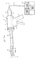
- FIG. 1 is a diagram showing a configuration of a bipolar treatment device (high frequency treatment device) 1 of the present embodiment.
- the bipolar treatment apparatus 1 includes a bipolar treatment instrument (handpiece) 2.
- the bipolar treatment instrument 2 has a longitudinal axis C.
- one of the directions parallel to the longitudinal axis C is the distal direction (the direction of the arrow C1 in FIG. 1), and the direction opposite to the distal direction is the proximal direction (the direction of the arrow C2 in FIG. 1).
- the bipolar treatment instrument 2 is an ultrasonic treatment instrument that performs treatment of a treatment target such as a living tissue using ultrasonic vibration.
- the bipolar treatment instrument 2 is a high-frequency treatment instrument that performs treatment on a treatment target using high-frequency energy (high-frequency current).
- the bipolar treatment instrument 2 includes a holding unit 3.
- the holding unit 3 is rotatable with respect to the cylindrical case portion 5 that extends along the longitudinal axis C, a fixed handle 6 that is formed integrally with the cylindrical case portion 5, and the cylindrical case portion 5.
- a movable handle 7 to be attached.
- the movable handle 7 opens or closes the fixed handle 6 by rotating the movable handle 7 around the attachment position to the cylindrical case portion 5.
- the holding unit 3 also includes a rotation operation knob 8 attached to the distal direction side of the cylindrical case portion 5.
- the rotation operation knob 8 is rotatable about the longitudinal axis C with respect to the cylindrical case portion 5.
- the fixed handle 6 is provided with an energy operation input button 9 that is an energy operation input unit.
- the bipolar treatment instrument 2 includes a vibrator unit 11.
- the vibrator unit 11 includes a vibrator case 12.
- the vibrator case 12 is rotatable with respect to the cylindrical case portion 5 around the longitudinal axis C integrally with the rotation operation knob 8.
- the vibrator case 12 is attached to the holding unit 3 by inserting the vibrator case 12 into the cylindrical case portion 5 from the proximal direction side.
- One end of a cable 13 is connected to the vibrator case 12.
- the bipolar treatment device 1 includes a control unit 15.
- the other end of the cable 13 is connected to the control unit 15.
- the control unit 15 includes a high-frequency energy source 16, an ultrasonic energy source 17, and an energy control unit 18.
- the high-frequency energy source 16 and the ultrasonic energy source 17 are, for example, power generators, and are formed from a power source, a conversion circuit, and the like.
- the energy control unit 18 includes, for example, a processor including a CPU (Central Processing Unit) or an ASIC (application specific integrated circuit), and a storage unit such as a memory.
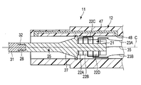
- FIG. 2 is a diagram showing a configuration of the vibrator unit 11.
- the transducer unit 11 includes an ultrasonic transducer 21 that is a vibration generating unit provided inside the transducer case 12.
- the ultrasonic transducer 21 includes a plurality (four in this embodiment) of piezoelectric elements 22A to 22D that convert a current into ultrasonic vibration.
- One end of each electric wiring 23A, 23B is connected to the ultrasonic transducer 21.
- the electric wires 23A and 23B are extended through the inside of the cable 13, and the other ends of the electric wires 23A and 23B are connected to the ultrasonic energy source 17 of the control unit 15.
- ultrasonic energy (ultrasonic current) is supplied from the ultrasonic energy source 17 to the ultrasonic vibrator 21 via the electrical wirings 23 ⁇ / b> A and 23 ⁇ / b> B, ultrasonic vibration is generated in the ultrasonic vibrator 21.
- the ultrasonic transducer 21 is attached to a columnar horn member 25.
- the horn member 25 includes a cross-sectional area changing portion 27 in which a cross-sectional area perpendicular to the longitudinal axis C changes.
- the ultrasonic vibration generated by the ultrasonic vibrator 21 is transmitted to the horn member 25 and is transmitted from the proximal direction to the distal direction in the horn member 25.
- the amplitude of the ultrasonic vibration transmitted to the horn member 25 is expanded by the cross-sectional area changing unit 27.
- a female screw portion 28 is provided at the tip of the horn member 25.
- the bipolar treatment instrument 2 includes a columnar probe 31 extending along the longitudinal axis C from the inside of the cylindrical case portion 5 toward the distal direction.
- the central axis of the probe 31 is coaxial with the longitudinal axis C.
- a male screw portion 32 is provided at the proximal end portion of the probe 31.
- the probe 31 is connected to the distal direction side of the horn member 25.
- the probe 31 is connected to the horn member 25 inside the cylindrical case portion 5.
- the ultrasonic vibrator 21, the horn member 25, and the probe 31 are rotatable with respect to the cylindrical case portion 5 around the longitudinal axis C integrally with the rotation operation knob 8.
- ultrasonic vibration is transmitted from the horn member 25 to the probe 31.
- ultrasonic vibration is transmitted along the longitudinal axis C from the proximal direction to the distal direction.
- a treatment portion 33 is provided at the distal end portion of the probe 31.
- ultrasonic vibration is transmitted to the treatment unit 33.
- the distal end of the probe 31 and the proximal end of the horn member 25 are antinode positions of ultrasonic vibration.
- the ultrasonic vibration is a longitudinal vibration in which the vibration direction and the transmission direction are parallel to the longitudinal axis C.
- an electrical wiring 35 is connected to the horn member 25.
- the electrical wiring 35 extends through the inside of the cable 13, and the other end of the electrical wiring 35 is connected to the high frequency energy source 16 of the control unit 15.
- a probe-side electrical path of high-frequency energy (high-frequency power) supplied from the high-frequency energy source 16 is formed from the high-frequency energy source 16 through the electrical wiring 35, the horn member 25, and the probe 31 to the treatment unit 33.
- the high frequency energy is transmitted (supplied) to the treatment unit 33 through the probe-side electric path, whereby the treatment unit 33 functions as an electrode. That is, the treatment portion 33 is a probe side electrode portion (first electrode portion) 36 that functions as one electrode of high frequency energy (high frequency current).
- the bipolar treatment instrument 2 includes a sheath 40 that extends along the longitudinal axis C.
- the sheath 40 is attached to the holding unit 3 by inserting the sheath 40 into the inside of the rotary operation knob 8 and the inside of the cylindrical case portion 5 from the distal direction side.
- a sheath 40 is attached to the distal side of the transducer case 12 inside the cylindrical case portion 5.
- a probe 31 is inserted through the sheath 40.
- the treatment portion 33 of the probe 31 protrudes from the distal end of the sheath 40 toward the distal direction.
- a jaw 60 as a gripping unit is rotatably attached to the distal end portion of the sheath 40.
- the jaw (gripping unit) 60 can be opened and closed with respect to the treatment portion 33.
- FIG. 3 is a diagram showing an internal configuration of the holding unit 3.
- the sheath 40 includes a connection tubular portion 41 formed of an insulating material (non-conductive material) and a movable tubular portion 42 provided on the outer peripheral direction side of the connection tubular portion 41.
- the movable cylindrical portion 42 is made of a conductive material, and is movable along the longitudinal axis C with respect to the vibrator case 12 and the connecting cylindrical portion 41.
- a slider member 43 formed of an insulating material (non-conductive material) is provided on the outer peripheral portion of the movable cylindrical portion 42. The slider member 43 is movable along the longitudinal axis C with respect to the movable cylindrical portion 42.
- the slider member 43 and the movable cylindrical portion 42 are connected via an elastic member 45 such as a coil spring.
- a movable handle 7 is attached to the slider member 43.
- the driving force is transmitted to the slider member 43, and the slider member 43 moves along the longitudinal axis C.
- a driving force is transmitted from the slider member 43 to the movable cylindrical portion 42 via the elastic member 45, and the movable cylindrical portion 42 moves along the longitudinal axis C with respect to the transducer case 12 and the connecting cylindrical portion 41.
- the vibrator case 12 has a case conductive portion 47 formed therein.
- One end of an electrical wiring 48 is connected to the case conductive portion 47.
- the electrical wiring 48 extends through the inside of the cable 13, and the other end of the electrical wiring 48 is connected to the high frequency energy source 16 of the control unit 15.
- a plate-like contact member 49 formed of a conductive material is fixed to the connection tubular portion 41 of the sheath 40. In a state where the sheath 40 is connected to the transducer case 12, the contact member 49 contacts the case conductive portion 47 of the transducer case 12, and the movable cylindrical member 42 contacts the contact member 49 so as to be movable.
- the case conductive portion 47 and the movable cylindrical portion 42 of the transducer case 12 are electrically connected via the contact member 49.
- the high frequency energy is supplied (transmitted) from the high frequency energy source 16 to the movable cylindrical portion 42 of the sheath 40 through the electrical wiring 48 and the case conductive portion 47 of the vibrator case 12.
- the case conductive portion 47 of the vibrator case 12 and the movable cylindrical portion 42 of the sheath 40 are electrically insulated from the horn member 25 and the probe 31.
- the energy control unit 18 controls the output state of the ultrasonic energy from the ultrasonic energy source 17 and the output state of the high frequency energy from the high frequency energy source 16 based on the input of the energy operation with the energy operation input button 9. Yes.
- a switch (not shown) is provided inside the fixed handle 6. When the energy operation input button 9 is pressed and the energy operation is input, the switch is closed. The switch is electrically connected to the energy control unit 18. When the switch is closed, an electric signal is transmitted to the energy control unit 18 and an input of energy operation is detected. By detecting the input of the energy operation, ultrasonic energy is output from the ultrasonic energy source 17 and high frequency energy is output from the high frequency energy source 16.
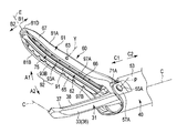
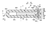
- FIG. 4 and 5 are diagrams illustrating the configuration of the distal end portion of the sheath 40, the distal end portion of the probe 31, and the jaw 60
- FIG. 6 is a diagram illustrating the configuration of the distal end portion of the sheath 40 and the jaw 60.
- 4 and 6 are perspective views, and in FIG. 6, each member is shown in a disassembled state.
- the jaw 60 as a gripping unit extends along an extending shaft (jaw shaft) E from the proximal direction to the distal direction.
- the extension axis E is the central axis of the jaw 60, and the extension axis E of the jaw 60 is substantially parallel to the longitudinal axis C when the jaw 60 is closed with respect to the treatment portion 33.
- One of the directions perpendicular to the longitudinal axis C and the extending axis E is the opening direction of the jaw 60 (the direction of the arrow A1 in FIG. 4), and the opposite direction to the opening direction is the closing direction of the jaw 60 (the arrow in FIG. 4). A2 direction).
- two directions perpendicular to the extending axis E (longitudinal axis C) and perpendicular to the opening / closing direction of the jaw 60 are defined as the width direction.
- One of the width directions is the first width direction (the direction of the arrow B1 in FIG. 4), and the other width direction is the second width direction (the direction of the arrow B2 in FIG. 4).
- FIG. 5 shows a cross section perpendicular to the width direction. 4 and 5 are shown with the jaw 60 opened to the treatment portion 33.
- a probe side bending portion 37 in which the treatment portion 33 (longitudinal axis C) is bent in the first width direction is formed at the distal end portion of the treatment portion 33.
- the jaw 60 is formed with a jaw-side bending portion 67 corresponding to the probe-side bending portion 37 in which the jaw 60 (extended shaft E) is bent in the first width direction.
- the jaw 60 is extended in a state of facing the probe side bending portion 37.
- the sheath 40 includes an inner tube 51 formed of an insulating material (non-conductive material), a movable pipe 52 provided on the outer peripheral side of the inner tube 51, and an outer periphery of the movable pipe 52.
- the outer pipe 53 provided on the direction side and the outer tube 50 provided on the outer peripheral direction side of the outer pipe 53 are provided.
- the movable pipe 52 and the outer pipe 53 are made of a conductive material, and the outer tube 50 is made of an insulating material (non-conductive material).
- the proximal end portion of the movable pipe 52 is connected to the distal end portion of the movable cylindrical portion 42.
- the movable pipe 52 When the driving force is transmitted to the movable pipe 52 by the closing operation of the movable handle 7 with respect to the fixed handle 6, the movable pipe 52 is integrated with the movable cylindrical portion 42 with respect to the inner tube 51, the outer pipe 53 and the outer tube 50. It moves along the longitudinal axis C. As the movable cylindrical portion 42 and the movable pipe 52 move along the longitudinal axis C, the jaw 60 opens or closes the treatment portion 33. Further, the high frequency energy transmitted from the high frequency energy source 16 to the movable cylindrical portion 42 is transmitted to the movable pipe 52 via a fuse pin (not shown).
- a high-frequency transmission unit (a jaw-side high-frequency transmission unit) is formed by the movable cylindrical portion 42 and the movable pipe 52 of the sheath 40.
- the probe 31 is inserted through the high-frequency transmission part (the movable cylindrical part 42 and the movable pipe 52). That is, the movable cylindrical portion 42 and the movable pipe 52 become a sheath conductive portion capable of transmitting a high-frequency current in the sheath 40.
- the movable pipe 52 which is a high-frequency transmission unit, is electrically insulated from the probe 31.
- the jaw 60 is attached to the distal end portion of the outer pipe 53 of the sheath 40 via fulcrum pins 55A and 55B.
- the jaw 60 rotates about a rotation axis P that is coaxial with the center axis of each fulcrum pin 55A, 55B.
- the rotation axis P is substantially parallel to the width direction (B1, B2).
- tip part (high frequency transmission part) of the movable pipe 52 is connected to the jaw 60 via the connection pin 56 which is a connection member.
- the high frequency energy transmitted to the movable pipe 52 is transmitted to the jaw 60 through the connection pin 56.
- a jaw side electric path is formed from the high frequency energy source 16 to the jaw 60 through the electric wiring 48, the case conductive portion 47 of the vibrator case 12, the movable cylindrical portion 42, and the movable pipe 52.
- High-frequency energy (high-frequency power) is transmitted (supplied) from the high-frequency energy source 16 to the jaw 60 by the jaw-side electric path.
- the jaw 60 as a gripping unit includes a support portion (a jaw main body portion) 61 attached to the sheath 40 and a swinging portion 62 that can swing relative to the support portion 61.
- the swing part 62 is connected to the support part 61 via a connection pin 63 that is a connection member.
- the swing part 62 swings with respect to the support part 61 about the swing axis Y.
- the swing axis Y is parallel to the width direction of the jaw 60 and is coaxial with the central axis of the connecting pin 63. In the present embodiment, the swing axis Y passes through the intermediate portion of the jaw 60 in the direction parallel to the extending axis E.
- the oscillating portion 62 includes a jaw side electrode portion 65 formed of a conductive material, and a pad member 66 attached to the jaw side electrode portion 65.
- the pad member 66 is made of an insulating material (non-conductive material).
- the high-frequency energy is transmitted (supplied) to the jaw-side electrode portion 65 of the jaw 60 via the jaw-side electric path described above, whereby the jaw-side electrode portion 65 functions as an electrode. That is, the jaw side electrode part (second electrode part) 65 functions as the other electrode of the high frequency energy (high frequency current) different from the probe side electrode part 36 (treatment part 33).
- the support portion 61 includes a support body 68 formed of a conductive material and an insulating coating portion 69 that is coated over the entire surface of the support body 68.
- an insulating surface treatment is performed on the entire surface, and the entire surface is formed by the insulating coating portion 69 (that is, an insulating material (non-conductive material)).
- the support main body 68 inside the support portion 61 is made of a conductive material, high-frequency energy (high-frequency current) can be transmitted inside the support portion 61.
- a pair of jaw projecting pieces 71 ⁇ / b> A and 71 ⁇ / b> B are provided at the base end portion of the support portion 61.
- the jaw protruding piece 71A is positioned on the first width direction side from the jaw protruding piece 71B, and a space is formed between the jaw protruding piece 71A and the jaw protruding piece 71B in the width direction.
- a through-hole 72A that penetrates the jaw projection piece 71A in the width direction is formed in the jaw projection piece 71A, and a through-hole 72B that penetrates the jaw projection piece 71B in the width direction is formed in the jaw projection piece 71B.
- a pair of sheath projecting pieces 57 ⁇ / b> A and 57 ⁇ / b> B are provided at the distal end portion of the outer pipe 53.
- a through-hole 58A that penetrates the sheath projection piece 57A in the width direction is formed in the sheath projection piece 57A
- a through-hole 58B that penetrates the sheath projection piece 57B in the width direction is formed in the sheath projection piece 57B.
- the sheath protruding piece 57A contacts the jaw protruding piece 71A from the first width direction side
- the sheath protruding piece 57B contacts the jaw protruding piece 71B from the second width direction side.
- the fulcrum pin 55A is inserted into the through hole 58A of the sheath projecting piece 57A and the through hole 72A of the jaw projecting piece 71A from the first width direction side, and the fulcrum pin 55B is Inserted into the through hole 58B of the sheath projecting piece 57B and the through hole 72B of the jaw projecting piece 71B from the second width direction side.
- a movable protrusion 54 is formed at the tip of the movable pipe 52.
- the movable protrusion 54 is located in the space between the jaw protrusion piece 71A and the jaw protrusion piece 71B in the width direction.
- a connection hole 73A that penetrates the jaw projection piece 71A in the width direction is formed in the jaw projection piece 71A, and a connection hole 73B that penetrates the jaw projection piece 71B in the width direction is formed in the jaw projection piece 71B.
- the movable protrusion 54 is formed with a through hole 59 that penetrates the movable protrusion 54 in the width direction.
- connection pin 56 is inserted through the connection hole 73A of the jaw projection piece 71A, the through hole 59 of the movable projection 54, and the connection hole 73B of the jaw projection piece 71B.
- the connection pin 56 comes into contact with the movable pipe 52 at the movable protrusion 54 and also comes into contact with the support main body 68 inside the support portion 61 at the jaw protruding piece 71A and the jaw protruding piece 71B. For this reason, high-frequency energy is transmitted from the movable pipe 52 (high-frequency transmission unit) to the inside of the support unit 61 without passing through the surface (insulating coating unit 68) of the support unit 61 by the connection pin 56 that is a connection member.
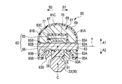
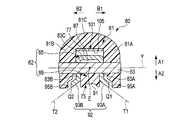
- FIG. 7 is a view showing the treatment portion 33 and the jaw 60 of the probe 31 in a cross section perpendicular to the longitudinal axis C (extension axis E), and FIG. 8 shows the jaw 60 in a cross section perpendicular to the extension axis E.
- FIG. 7 and 8 a cross section passing through the swing axis Y of the swing portion 62 is shown.
- the jaw 60 is shown closed with respect to the treatment portion 33.
- the swinging portion 62 includes a jaw-side facing surface 75 that faces the treatment portion 33 and faces the closing direction of the jaw 60 (the direction of the arrow A ⁇ b> 2 in FIGS. 7 and 8).
- the jaw side facing surface 75 is formed by the jaw side electrode portion 65 and the pad member 66.
- the support portion 61 has a swinging portion from the front end direction, both width directions (first width direction B1 and second width direction B2) and the opening direction of the jaw 60 (direction of arrow A1 in FIGS. 7 and 8). 62 is covered.
- the swinging part 62 is exposed to the outside only at the jaw side facing surface 75. Therefore, only the jaw side facing surface 75 is an exposed surface (outer surface) that is exposed to the outside on the surface of the oscillating portion 62, and portions other than the jaw side facing surface 75 are not exposed to the outside. (Inner surface).
- the support portion 61 covers the swinging portion 62 in such a state that a gap that allows the swinging portion 62 to swing is formed between the support portion 61 and the swinging portion 62.
- a receiving surface 76 facing the closing direction of the jaw 60 is provided on the inner surface (non-exposed surface) of the support portion 61.
- a contact surface 77 is provided on the inner surface of the oscillating portion 62 (jaw side electrode portion 65) so as to face the receiving surface 76 and face the opening direction of the jaw 60.
- the contact surface 77 can contact the receiving surface 76.
- the swing part 62 can swing in the first swing direction (the direction of the arrow Y1 in FIG. 5) and the second swing direction (the direction of the arrow Y2 in FIG. 5).
- the support portion 61 includes a first support wall portion 81A that covers the swing portion 62 from the first width direction side, and a second support wall portion 81B that covers the swing portion 62 from the second width direction side.
- the support portion 61 includes a third support wall portion 81 ⁇ / b> C that covers the swing portion 62 from the opening direction side of the jaw 60, and a fourth support wall portion (a tip support wall that covers the swing portion 62 from the tip direction side). Part) 81D.
- the receiving surface 76 with which the contact surface 77 of the swinging portion 62 can contact is formed on the surface (inner surface) of the third support wall portion 81C.
- the first support wall portion 81A has a through hole 82A that penetrates the first support wall portion 81A in the width direction
- the second support wall portion 81B has a second support wall portion 81B in the width direction.
- a through hole 82 ⁇ / b> B that penetrates through is formed.
- the jaw side electrode portion 65 includes a first electrode plate portion 83A that covers the pad member 66 from the first width direction side, and a second electrode plate portion 83B that covers the pad member 66 from the second width direction side. Prepare.
- the jaw side electrode portion 65 is provided with a third electrode plate portion 83 ⁇ / b> C that covers the pad member 66 from the opening direction side of the jaw 60.
- a contact surface 77 that can contact the receiving surface 76 of the support portion 61 is formed on the surface (non-exposed surface) of the third electrode plate portion 83C.
- a through-hole 85A that penetrates the first electrode plate portion 83A in the width direction is formed in the first electrode plate portion 83A, and the second electrode plate portion 83B in the width direction is formed in the second electrode plate portion 83B.
- a through-hole 85B that penetrates through is formed.
- a pad fixing surface 86 that is fixed to the third electrode plate portion 83 ⁇ / b> C of the jaw side electrode portion 65 is provided on the surface (inner surface) of the pad member 66.
- the pad fixing surface 86 faces the opening direction of the jaw 60 and forms an end of the pad member (insulating contact member) 66 on the opening direction side.
- the pad member 66 is formed with a through groove 87 that penetrates the pad member 66 in the width direction.
- the through groove 87 is recessed from the pad fixing surface 86 in the closing direction of the jaw 60.
- the connecting pin 63 which is a connecting member, passes through the through hole 82A of the first support wall 81A, the through hole 85A of the first electrode plate portion 83A, the through groove 87 of the pad member 66, and the second electrode plate portion 83B.
- the hole 85B and the through hole 82B of the second support wall 81B are inserted.
- the connection pin 63 is in contact with the jaw-side electrode portion 65 at the first electrode plate portion 83A and the second electrode plate portion 83B, and at the first support wall portion 81A and the second support wall portion 81B, 61 is in contact with the support body 68 inside. For this reason, the high frequency energy is transmitted from the inside of the support portion 61 to the jaw side electrode portion 65 without passing through the surface (insulating coating portion 68) of the support portion 61 by the connecting pin 63 which is a connecting member.
- a probe side electrode surface (probe side facing surface) 38 facing the jaw side facing surface 75 is formed on the treatment portion 33 which becomes the probe side electrode portion 36.
- the treatment portion 33 is formed in a substantially octagonal shape.
- the jaw side facing surface 75 includes a contact portion (contact surface) 91 that can contact the treatment portion 33 when the jaw 60 is closed with respect to the treatment portion 33.
- the contact portion 91 contacts the probe side electrode surface 38 of the treatment portion 33.
- the contact portion 91 is formed on the pad member 66 and has electrical insulation. Further, the contact portion 91 faces the closing direction of the jaw 60.
- the jaw side facing surface 75 includes a jaw side electrode surface 92 formed by the jaw side electrode portion 65.
- the surface of the jaw side electrode portion 65 is exposed to the outside only at the jaw side electrode surface 92.
- the jaw side electrode surface 92 (jaw side electrode portion 65) is separated from the probe side electrode portion 36 (treatment portion 33). For this reason, contact with the jaw side electrode part 65 and the probe side electrode part 36 is prevented effectively.
- the jaw side electrode surface 92 includes a first jaw side electrode surface 93A provided on the first width direction side of the contact portion 91 and a second jaw side provided on the second width direction side of the contact portion 91. Electrode surface 93B.
- the first jaw side electrode surface 93 ⁇ / b> A is inclined by an acute angle ⁇ ⁇ b> 1 toward the first width direction with respect to the closing direction of the jaw 60 in a cross section perpendicular to the extending axis E.
- the second jaw side electrode surface 93B is inclined by an acute angle ⁇ 2 toward the second width direction with respect to the closing direction of the jaw 60 in a cross section perpendicular to the extending axis E.
- the first jaw side electrode surface 93 ⁇ / b> A serves as a first end forming surface that forms the first width direction end Q ⁇ b> 1 of the jaw side facing surface 75.
- the second jaw side electrode surface 93 ⁇ / b> B serves as a second end forming surface that forms the second width direction end Q ⁇ b> 2 of the jaw side facing surface 75.
- the first jaw side electrode surface (first end forming surface) 93A is defined as a first virtual surface T1 extending in the first width direction side
- the second jaw side electrode surface (second The second imaginary surface T2 obtained by extending the end forming surface 93B to the second width direction side is defined.
- the first imaginary plane T1 is inclined by an acute angle ⁇ 1 toward the first width direction with respect to the closing direction of the jaw 60 in a cross section perpendicular to the extending axis E.
- the second virtual surface T2 is inclined by an acute angle ⁇ 2 toward the second width direction with respect to the closing direction of the jaw 60 in a cross section perpendicular to the extending axis E.
- the first support wall portion 81A of the support portion 61 is provided in a state where it does not protrude in the closing direction of the jaw 60 from the first virtual surface T1. That is, the end of the first support wall portion 81A on the closing direction side is located closer to the opening direction than the first virtual surface T1. Further, the second support wall portion 81B of the support portion 61 is provided in a state where it does not protrude from the second virtual surface T2 in the closing direction of the jaw 60. That is, the end of the second support wall portion 81B on the closing direction side is located on the opening direction side with respect to the second virtual surface T2.
- a gap 95A is formed between the first jaw side electrode surface 93A and the first support wall 81A in the width direction. Further, a gap 95B is formed between the second jaw side electrode surface 93B and the second support wall 81B in the width direction. In each gap 95A, 95B, the dimension in the width direction is 0.1 mm to 0.2 mm.
- a first convex concave portion 97A is provided on the first jaw side electrode surface 93A
- a second convex concave portion 97B is provided on the second jaw side electrode surface 93B.
- the edge (first width direction end Q1) of the first jaw side electrode surface 93A is formed in a convex shape.
- the convex direction and the concave direction in the first convex concave portion 97A are parallel to the first jaw side electrode surface 93A and perpendicular to the extending axis E of the jaw 60.
- the second width side edge (second width direction end Q2) of the second jaw side electrode surface 93B is formed in a convex shape.
- the convex direction and the concave direction in the second convex concave portion 97B are parallel to the second jaw side electrode surface 93B and perpendicular to the extending axis E of the jaw 60.
- each of the convex and concave portions 97A and 97B extends substantially parallel to the extending axis E.
- the operation and effect of the bipolar treatment tool 2 (bipolar treatment device 1) of this embodiment will be described.
- a treatment target such as a biological tissue (blood vessel)
- the treatment portion 33 and the jaw 60 are inserted into the body. Then, it is positioned between the jaw 60 and the treatment portion 33 as a treatment target.
- the jaw 60 is closed with respect to the treatment portion 33, and the treatment target is gripped between the swinging portion 62 of the jaw 60 and the treatment portion 33.
- the jaw-side facing surface 75 provided on the swinging portion 62 contacts the treatment target.
- the swinging part 62 provided with the jaw side facing surface 75 can swing around the swinging axis Y with respect to the support part 61. For this reason, even when the distal end portion of the jaw side facing surface 75 (the distal end portion of the jaw 60) abuts on the treatment target, the proximal end portion of the jaw side facing surface 75 (the proximal end portion of the jaw 60) abuts on the treatment target. In this case, the gripping force of the treatment target between the jaw 60 and the treatment portion 33 is substantially the same.
- the gap between the jaw 60 and the treatment portion 33 is changed.
- the gripping force at is kept substantially uniform.
- the energy operation is input by the energy operation input button 9.
- ultrasonic energy (ultrasonic power) is output from the ultrasonic energy source 17
- high frequency energy (high frequency power) is output from the high frequency energy source 16.
- ultrasonic energy (ultrasonic current) is supplied to the ultrasonic transducer 21
- ultrasonic vibration is generated.
- the generated ultrasonic vibration is transmitted to the probe 31 through the horn member 25, and the ultrasonic vibration is transmitted along the longitudinal axis C from the proximal direction to the distal direction in the probe 31.
- the ultrasonic vibration is transmitted to the treatment portion 33, so that the treatment portion 33 vibrates parallel to the longitudinal axis C.
- the high frequency energy is transmitted to the probe side electrode section 36 (treatment section 33) through the probe side electric path, and is transmitted to the jaw side electrode section 65 of the jaw 60 through the jaw side electric path.
- the probe side electrode part 36 functions as one electrode of high frequency energy
- the jaw side electrode part 65 functions as the other electrode of high frequency energy.
- the treatment portion 33 vibrates, and frictional heat is generated between the treatment portion 33 and the gripping target.
- frictional heat the object to be treated is coagulated at the same time as the cut.
- a high-frequency current flows through the treatment target between the probe-side electrode portion 36 (probe-side electrode surface 38) and the jaw-side electrode portion 65 (jaw-side electrode surface 92). Thereby, the treatment object is denatured and the coagulability of the treatment object is improved.
- the swinging part 62 is covered with the support part 61 from the front end direction, both width directions and the jaw opening direction, and the surface of the swinging part 62 is externally only on the jaw side facing surface 75. Exposed. For this reason, on the exposed surface of the jaw 60, the portion facing the width direction (the first width direction and the second width direction), the portion facing the tip direction, and the portion facing the opening direction of the jaw 60 are supported. Only the portion 61 is formed. Accordingly, in the exposed surface of the jaw 60, there are gaps between the portions facing the width direction (the first width direction and the second width direction), the portion facing the tip direction, and the portion facing the opening direction of the jaw 60, respectively. Etc. are not formed.
- the entire surface (outer surface and inner surface) of the support portion 61 is covered with an insulating coating portion 69. For this reason, high frequency energy (high frequency current) is not transmitted through the surface of the support portion 61. Therefore, even when the outer surface (exposed surface) of the support part 61 contacts a living tissue or the like at a place other than the treatment target, the high-frequency current is not discharged from the exposed surface of the support part 61. Further, in the swinging part 62, only the jaw side facing surface 75 is exposed to the outside, and parts other than the jaw side facing surface 75 do not contact the living tissue. For this reason, the discharge of the high frequency current from places other than the jaw side electrode surface 92 of the jaw side opposing surface 75 is prevented effectively. Thereby, the current density of the high frequency current which flows into the treatment target grasped between the swinging portion 62 of the jaw 60 and the treatment portion 33 is increased, and the treatment performance by the high frequency energy can be ensured.
- the entire surface (outer surface and inner surface) of the support portion 61 is subjected to an insulating surface treatment. Therefore, the surface treatment of the support portion 61 is simplified as compared with the case where the insulating surface treatment is partially performed. Thereby, the jaw 60 is easily manufactured and the manufacturing cost of the jaw 60 can be suppressed.
- high frequency energy is transmitted from the movable pipe 52 (high frequency transmission portion) of the sheath 40 to the support body 68 inside the support portion 61 through the connection pin 56. Then, the high frequency energy is transmitted from the inside of the support portion 61 to the jaw side electrode portion 65 through the connecting pin 63. That is, high frequency energy is transmitted to the jaw side electrode portion 65 without passing through the surface of the support portion 61. Therefore, even if the entire surface of the support portion 61 has insulating properties, high-frequency energy can be appropriately transmitted to the jaw side electrode portion 65.
- the first support wall 81A that covers the swinging part 62 from the first width direction side extends the first jaw side electrode surface (first end forming surface) 93A to the first width direction side. It does not protrude in the closing direction of the jaw 60 from the first virtual surface T1.
- swiveling part 62 from the 2nd width direction side extended the 2nd jaw side electrode surface (2nd end formation surface) 93B to the 2nd width direction side. It does not protrude in the closing direction of the jaw 60 from the second virtual surface T2.
- the jaw-side facing surface 75 of the swinging portion 62 is provided with a first convex concave portion 97A and a second convex concave portion 97B.
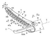
- FIG. 9 is a diagram showing the configuration of the distal end portion of the sheath 40, the distal end portion of the probe 31, and the jaw 60.
- FIG. 10 is a view showing the configuration of the distal end portion of the sheath 40 and the jaw 60
- FIGS. 11 and 12 are views showing the configuration of the jaw 60.
- 9 is shown in a cross section perpendicular to the width direction (the direction of the arrow B1 and the direction of the arrow B2 in FIGS. 10 and 12)
- FIG. 10 is an opening / closing direction of the jaw 60 (the arrow A1 in FIGS. 9 and 12).
- 11 shows a state where each member is disassembled
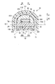
- FIG. 12 shows a cross section perpendicular to the extending axis E and passing through the swing axis Y.
- the jaw 60 which is a gripping unit, is provided with a support portion 61 and a swinging portion 62.
- the entire support portion 61 is formed of an insulating material (non-conductive material).
- the support part 61 is entirely formed of a material having low heat conductivity, and the heat transferability is low in the support part 61.
- the support portion 61 is made of, for example, a resin material such as PI or PEEK, or a foamable resin or ceramic.
- the relay member is interposed between the third support wall portion 81C of the support portion 61 and the third electrode plate portion 83C of the jaw side electrode portion 65 of the swinging portion 62 in the opening / closing direction of the jaw 60.
- 101 is provided.
- the relay member 101 is made of a conductive material and is provided in a state where it is not exposed to the outside.
- the relay member 101 extends substantially parallel to the extending shaft E.
- the relay member 101 is fixed to the third support wall portion 81 ⁇ / b> C of the support portion 61. Therefore, the swing part 62 is attached to the relay member 101 so as to be swingable about the swing axis Y.
- the relay member 101 is located away from the contact surface 77 of the jaw side electrode portion 65 that forms the end of the swinging portion 62 on the opening direction side.
- a pair of member projecting pieces 102 ⁇ / b> A and 102 ⁇ / b> B are provided at the proximal end portion of the relay member 101.
- a connecting hole 103A that penetrates the member protruding piece 102A in the width direction is formed in the member protruding piece 102A, and a connecting hole 103B that passes through the member protruding piece 102B in the width direction is formed in the member protruding piece 102B.
- the member protruding piece 102A is arranged between the jaw protruding piece 71A and the movable protrusion 54 in the width direction
- the member protruding piece 102B is arranged between the jaw protruding piece 71B and the movable protrusion 54 in the width direction.
- the connection pin 56 includes the connection hole 73A of the jaw protrusion piece 71A, the connection hole 103A of the member protrusion piece 102A, the through hole 59 of the movable protrusion 54, the connection hole 103B of the member protrusion piece 102B, and the jaw protrusion piece 71A. It is inserted through the connection hole 73B.
- connection pin 56 is in contact with the movable pipe 52 at the movable protrusion 54 and is in contact with the relay member 101 at the member protruding piece 102A and the member protruding piece 102B. For this reason, high-frequency energy is transmitted from the movable pipe 52 (high-frequency transmission unit) to the relay member 101 by the connection pin 56 that is a connection member without passing through the support portion 61 that has insulation properties.
- the distal end of the relay member 101 is located on the distal direction side with respect to the swing axis Y.
- the relay member 101 is extended to a position on the distal direction side from the swing shaft Y.
- the relay member 101 is provided with a receiving surface 105 facing the closing direction of the jaw 60.
- the swinging portion 62 swings in the first swinging direction (the direction indicated by the arrow Y1 in FIG. 9) or the second swinging direction (the direction indicated by the arrow Y2 in FIG. 9).
- a contact surface (electric contact surface) 77 contacts the receiving surface 105 of the relay member 101.
- the contact surface (electrical contact surface) 77 of the jaw side electrode portion 65 comes into contact with the receiving surface 105 of the relay member 101, so that the jaw side electrode from the relay member 101 does not pass through the support portion 61 that has insulating properties as a whole. High frequency energy is transmitted to the portion 65. Since the distal end of the relay member 101 is located on the distal direction side with respect to the swing shaft Y, a portion on the distal direction side from the swing shaft Y is separated from the treatment portion 33 (toward the first swing direction). Even when the swinging portion 62 swings, the contact surface 77 contacts the relay member 101.
- the swinging part 62 is covered with the support part 61 from the front end direction, both width directions and the jaw opening direction, and the surface of the swinging part 62 is externally only on the jaw side facing surface 75. Exposed.
- the relay member 101 is provided so as not to be exposed to the outside. For this reason, as in the first embodiment, catching and clogging of the living tissue other than the treatment target on the jaw 60 is effectively prevented. Further, similarly to the first embodiment, since the discharge of the high-frequency current from the portion other than the jaw side electrode surface 92 is effectively prevented, the gripping between the swinging portion 62 of the jaw 60 and the treatment portion 33 is performed. The current density of the high-frequency current flowing through the treatment target is increased.
- the entire support portion 61 is formed of an insulating material, it is not necessary to perform a surface treatment such as an insulating surface treatment in manufacturing the support portion 61. For this reason, the jaw 60 is more easily manufactured, and the manufacturing cost of the jaw 60 can be further suppressed. Further, since the entire support portion 61 is made of an insulating material and a material having low thermal conductivity, the support portion 61 has low heat transferability. For this reason, heat generated in the vicinity of the jaw-side facing surface 75 in the treatment is hardly transmitted to the outer surface (exposed surface) of the support portion 61. Thereby, even when the support part 61 contacts a living tissue or the like other than the treatment target, thermal damage to the living tissue is effectively prevented. Furthermore, heat used for the treatment is efficiently transmitted only to a treatment target such as a living tissue grasped between the jaw side facing surface 75 (pad member 66) and the treatment portion 33. For this reason, the treatment performance for treating the treatment target is improved.
- the bipolar treatment instrument 2 high frequency energy is transmitted to the relay member 101 through the connection pin 56 from the movable pipe 52 (high frequency transmission unit) of the sheath 40. Then, when the contact surface (electrical contact surface) 77 of the jaw side electrode portion 65 comes into contact with the relay member 101, high frequency energy is transmitted from the relay member 101 to the jaw side electrode portion 65. That is, high frequency energy is transmitted to the jaw side electrode portion 65 without passing through the support portion 61 formed of an insulating material. Therefore, even if the entire support portion 61 has insulating properties, high-frequency energy can be appropriately transmitted to the jaw side electrode portion 65. Further, the distal end of the relay member 101 is located on the distal direction side with respect to the swing axis Y.
- the first jaw concave electrode 97A is provided on the edge of the first jaw side electrode surface 93A (the end Q1 of the jaw side facing surface 75 on the first width direction side), and the second jaw side electrode surface 93A is provided.
- the second convex concave portion 97B is provided at the edge of the side electrode surface 93B (end Q2 on the second width direction side of the jaw side facing surface 75)
- the present invention is not limited to this.
- a first convex concave portion 97A is provided on the surface (exposed surface) of the first jaw side electrode surface 93A, and the surface of the second jaw side electrode surface 93B.
- a second convex concave portion 97B may be provided on the (exposed surface).
- the convex direction and the concave direction of the first convex concave portion 97A are perpendicular to the first jaw side electrode surface 93A
- the convex direction and concave direction of the second convex concave portion 97B are the second It is perpendicular to the jaw side electrode surface 93B.
- the first convex concave portion 97 ⁇ / b> A and the second convex concave portion 97 ⁇ / b> B are extended substantially parallel to the extending axis E of the jaw 60.
- a convex recess 97 is provided on the surface (exposed surface) of the contact portion (contact surface) 91 of the pad member 66 instead of the convex recesses 97A and 97B. May be.
- the convex direction and the concave direction of the convex concave portion 97 are perpendicular to the contact portion 91.
- the convex recess 97 extends substantially parallel to the extending axis E of the jaw 60.
- the jaw-side facing surface 75 may be provided with a convex concave portion (97A, 97B; 97) whose surface or edge is formed in a concave shape.
- a convex concave portion (97A, 97B; 97) whose surface or edge is formed in a concave shape.
- the ultrasonic vibration is transmitted to the treatment unit 33, but the ultrasonic vibration may not be transmitted to the treatment unit 33.
- the swing member 62 is not provided with the pad member 66, and the swing portion 62 is formed only from the jaw side electrode portion 65. In this modification, no ultrasonic vibration is generated, and the ultrasonic energy source 17 and the ultrasonic vibrator 21 are not provided.
- the treatment portion 33 is provided with a receiving portion 107 made of an insulating material in addition to the probe side electrode portion 36.
- the receiving part 107 protrudes from the probe side electrode part 36 (probe side electrode surface 38) toward the opening direction (direction of arrow A1 in FIG. 15).
- the entire jaw side facing surface 75 becomes the jaw side electrode surface 92.
- the jaw side electrode surface 92 includes a third jaw side electrode in addition to the first jaw side electrode surface (first end forming surface) 93A and the second jaw side electrode surface (second end forming surface) 93B.
- a surface 93C is provided.
- the third jaw side electrode surface 93C is extended between the first jaw side electrode surface 93A and the second jaw side electrode surface 93B in the width direction. And vertical.
- the third jaw side electrode surface 93C can come into contact with the receiving portion 107 of the treatment portion 33. That is, in the present modification, the third jaw side electrode surface 93 ⁇ / b> C closes the jaw 60 in a state where a treatment target such as a living tissue is not disposed between the jaw 60 and the treatment portion 33, thereby receiving the treatment portion 33. It becomes a contact portion that contacts the portion 107. In a state where the third jaw side electrode surface 93C as the contact portion is in contact with the receiving portion 107, the jaw side electrode surface 92 (jaw side facing surface 75) is in contact with the probe side electrode portion 36 (probe side electrode surface 38). It is away from. Therefore, also in this modification, contact with the jaw side electrode part 65 and the probe side electrode part 36 is prevented.
- the swinging portion 62 of the jaw 60 may be provided with a contact portion (91; 93C) that can contact the treatment portion 33 on the jaw-side facing surface 75.
- the contact portion (91; 93C) In the state where the contact portion (91; 93C) is in contact with the treatment portion 33, the jaw side electrode portion 65 only needs to be separated from the probe side electrode portion.
- the swinging part 62 has a tip direction, both width directions (the direction of arrow B1 and the direction of arrow B2 in FIG. 16), and the jaw 60. Is covered by the support 61 from the opening direction (in the direction of arrow A1 in FIG. 16), and is exposed to the outside only at the jaw-side facing surface 75.
- a filling member 111A is filled in a gap 95A between the first jaw side electrode surface (first end forming surface) 93A and the first support wall portion 81A in the width direction.
- the filling member 111B is filled in the gap 95B between the second jaw side electrode surface (second end forming surface) 93B and the second support wall portion 81B in the width direction.
- the filling members 111A and 111B have elasticity and are, for example, gels such as ⁇ gel.
- the filling member 111A is filled in the gap 95A, and the filling member 111B is filled in the gap 95B. For this reason, in the treatment, catching and clogging of the grasped treatment object and the solidified treatment object into the gaps 95A and 95B are effectively prevented. Further, since the filling members 111A and 111B have elasticity, the swinging part 62 can swing with respect to the support part 61 even when the filling member (111A or 111B) corresponding to the gaps 95A and 95B is filled. is there.
- the support part 61 and the swing part 62 are different from that of the first embodiment, the support part 61 and the swing part
- the cross-sectional shape perpendicular to the extending axis E of 62 is not limited to the shapes of the first embodiment and this modification. That is, the swing part 62 is covered with the support part 61 from the front end direction, both width directions and the opening direction of the jaw 60, and the swing part 62 is exposed to the outside only at the jaw side facing surface 75.
- the support part 61 and the swing part 62 should just be formed in the possible shape.
- the fifth modification will be described with reference to FIGS. 17 to 19.
- a cover member 113 is attached to the support portion 61.
- the cover member 113 covers the support portion 61 from the front end direction, both width directions (first width direction and second width direction), and the opening direction of the jaw 60.
- the cover member 113 is made of a material having insulating properties and heat insulating properties such as resin.
- the cover member 113 covers the outer surface of the support portion 61. Thereby, the contact of the support part 61 to living tissues other than the treatment target is effectively prevented. Further, the cover member 113 is formed of a material having heat insulation properties and has low heat transferability. For this reason, even when the outer surface (exposed surface) of the cover member 113 is in contact with a living tissue or the like other than the treatment target, thermal damage to the living tissue is effectively prevented.
- the outer surface of the support portion 61 exposed to the outside without being covered by the cover member 113 is a first outer surface 115A facing the first width direction (the direction of arrow B1 in FIGS. 17 and 19). , And a second outer surface 115B facing the second width direction (the direction of arrow B2 in FIGS. 17 and 19). Further, the outer surface of the support portion 61 faces the third outer surface 115C facing the opening direction of the jaw 60 (the direction of the arrow A1 in FIGS. 17 and 19) and the tip direction (the direction of the arrow C1 in FIG. 17). A fourth outer surface (tip outer surface) 115D.
- the first outer surface 115A is the outer surface of the first support wall portion 81A
- the second outer surface 115B is the outer surface of the second support wall portion 81B
- the third outer surface 115C is an outer surface of the third support wall portion 81C
- the fourth outer surface 115D is an outer surface of the fourth support wall portion 81D.
- the support portion 61 is attached to the cover member 113 at the three connection positions of the first connection position Z1, the second connection position Z2, and the third connection position Z3. It is connected.
- the first connection position Z ⁇ b> 1 is located on the proximal direction side of the swing axis Y on the first outer surface 115 ⁇ / b> A of the support portion 61.
- 117 A of engagement holes are provided in the 1st connection position Z1 of the support part 61.
- the cover member 113 is provided with a through hole 118A corresponding to the engagement hole 117A.
- connection pin 119A is inserted into the through hole 118A and engaged with the engagement hole 117A, whereby the support portion 61 is connected to the cover member 113 at the first connection position Z1.
- the second connection position Z2 is located on the proximal direction side of the swing axis Y on the second outer surface 115B of the support portion 61.
- An engagement hole 117 ⁇ / b> B is provided at the second connection position Z ⁇ b> 2 of the support portion 61.
- the cover member 113 is provided with a through hole 118B corresponding to the engagement hole 117B.
- the connection pin 119B is inserted into the through hole 118B and engaged with the engagement hole 117B, whereby the support portion 61 is connected to the cover member 113 at the second connection position Z2.
- the jaw central plane X which is a plane passing through the central position of the jaw 60 in the width direction.
- An extending axis E that is the central axis of the jaw 60 extends on the jaw central plane X.
- the third connection position Z3 is located on the fourth outer surface (tip outer surface) 115D of the support portion 61, and the jaw center plane X passes through the third connection position Z3.
- the third connection position Z3 is located on the fourth outer surface 115D, it is located on the distal direction side with respect to the swing axis Y.
- an engagement protrusion 121 that protrudes toward the distal end direction is provided.
- the cover member 113 is provided with an engagement hole 122 corresponding to the engagement protrusion 121.
- the engagement protrusion 121 engages with the engagement hole 122, whereby the support portion 61 is connected to the cover member 113 at the third connection position Z3.
- the cover member 113 can be easily and simply attached to the support part 61 easily and simply. Realized by configuration.
- the third connection position Z3 is located on the fourth outer surface (tip outer surface) 115D, and the jaw center plane X passes through the third connection position Z3, but this is not limitative. It is not a thing.
- the jaw center plane X passes through the third connection position Z3 and the third connection position Z3 is located on the distal direction side with respect to the swing axis Y, the jaw 60 is opened.
- the third connection position Z3 may be located on the third outer surface 115C facing the direction.
- the jaw center plane X does not pass through the third connection position Z3. Also good.
- the configuration in which the support portion 61 is connected to the cover member 113 is the configuration of this modification. It is not limited.
- an engagement hole (not shown) is provided in the third connection position Z3 of the support portion 61, and an engagement protrusion (not shown) is provided in the cover member 113 so as to correspond to the engagement hole. May be.
- the gap 123 between the support portion 61 and the cover member 113 may be filled with a filling member (not shown) formed from a heat insulating material.
- the filling member is a gel such as an ⁇ gel.
- the swing axis Y of the swing part 62 is parallel to the width direction, but is not limited thereto.
- the rocking shaft (Y) of the rocking portion 62 may be provided in parallel to the extending shaft E.
- the connecting pin 63 is used as a connecting member that connects the swinging part 62 to the support part 61 so as to be swingable.
- the present invention is not limited to this.
- a spring may be used as a connecting member as in Patent Document 1
- a joint ball may be used as a connecting member.
- the gripping unit (jaw 60) includes a support portion (61) that prevents transmission of high-frequency energy through the surface by forming at least the entire surface from an insulating material.
- the gripping unit (60) is provided with a swing part (62) that can swing with respect to the support part (61) about the swing axis (Y).
- the swing part (62) functions as an electrode different from the jaw side facing surface (75) facing the treatment part (33) and the probe side electrode part (36) by transmitting high frequency energy.
- the jaw side electrode portion (65), and the jaw side facing surface (75) includes a jaw side electrode surface (92) formed from the jaw side electrode portion (65).
- the swinging part (62) covers the swinging part (62) from the tip direction (C1), both width directions (B1 and B2) and the opening direction (A1) of the jaw (60), And the rocking
Abstract
Description
本発明の第1の実施形態について、図1乃至図8を参照して説明する。
次に、本発明の第2の実施形態について、図9乃至図12を参照して説明する。第2の実施形態は、第1の実施形態の構成を次の通り変形したものである。なお、第1の実施形態と同一の部分については同一の符号を付して、その説明は省略する。
なお、前述の実施形態では、第1のジョー側電極面93Aの縁(ジョー側対向面75の第1の幅方向側の端Q1)に第1の凸凹部97Aが設けられ、第2のジョー側電極面93Bの縁(ジョー側対向面75の第2の幅方向側の端Q2)に第2の凸凹部97Bが設けられているが、これに限るものではない。例えば、第1の変形例として図13に示すように、第1のジョー側電極面93Aの表面(露出面)に第1の凸凹部97Aが設けられ、第2のジョー側電極面93Bの表面(露出面)に第2の凸凹部97Bが設けられてもよい。本変形例では、第1の凸凹部97Aの凸方向及び凹方向は、第1のジョー側電極面93Aに対して垂直であり、第2の凸凹部97Bの凸方向及び凹方向は、第2のジョー側電極面93Bに対して垂直である。本変形例でも、第1の凸凹部97A及び第2の凸凹部97Bは、ジョー60の延設軸Eに略平行に延設されている。本変形例でも、第1の凸凹部97A及び第2の凸凹部97Bによって、揺動部62と処置部33との間で処置対象を把持した際に、処置対象の延設軸E(長手軸C)に沿った移動が規制される。
Claims (18)
- 基端方向から先端方向へ延設軸に沿って延設され、プローブの先端部に設けられる処置部に対して開閉可能な把持ユニットであって、
少なくとも表面全体が絶縁材料から形成されることにより、前記表面を通しての高周波エネルギーの伝達が防止される支持部と、
前記処置部に対して対向するジョー側対向面と、前記高周波エネルギーが伝達されることにより、前記処置部に形成されるプローブ側電極部とは別の電極として機能するジョー側電極部と、を備え、揺動軸を中心として前記支持部に対して揺動可能に設けられる揺動部であって、前記ジョー側対向面は、前記ジョー側電極部から形成されるジョー側電極面を備える、揺動部と、
前記延設軸に垂直で、かつ、前記把持ユニットの開閉方向に垂直な2方向を幅方向とした場合に、前記先端方向、両方の前記幅方向及び前記把持ユニットの開方向から前記支持部が前記揺動部を覆い、かつ、前記揺動部が前記ジョー側対向面でのみ外部に対して露出する状態に、前記揺動部を前記支持部に揺動可能に連結する連結部材と、
を具備する把持ユニット。 - 前記支持部は、内部が導電材料から形成され、
前記ジョー側電極部には、前記支持部の前記内部から前記連結部材を通して、前記高周波エネルギーが伝達される、
請求項1の把持ユニット。 - 請求項2の把持ユニットと、
前記処置部を備え、前記プローブ側電極部が前記処置部に形成されるプローブと、
前記処置部が前記先端方向へ向かって突出する状態で前記プローブが挿通され、導電材料から形成される高周波伝達部と、
前記高周波伝達部と前記支持部との間を接続し、前記高周波伝達部から前記支持部の前記内部に前記高周波エネルギーを伝達する接続部材と、
を具備するバイポーラ処置具。 - 前記支持部は、全体が絶縁材料から形成され、
前記把持ユニットは、導電材料から形成され、前記外部に対して露出しない状態で前記把持ユニットの前記開閉方向について前記支持部と前記揺動部との間に設けられる中継部材であって、前記揺動部が前記揺動軸を中心として揺動可能に取付けられる中継部材をさらに備え、
前記ジョー側電極部は、前記揺動部の揺動によって前記中継部材に接触することにより、前記中継部材から前記高周波エネルギーが伝達される電気接触面を備える、
請求項1の把持ユニット。 - 請求項4の把持ユニットと、
前記処置部を備え、前記プローブ側電極部が前記処置部に形成されるプローブと、
前記処置部が前記先端方向へ向かって突出する状態で前記プローブが挿通され、導電材料から形成される高周波伝達部と、
前記高周波伝達部と前記中継部材との間を接続し、前記高周波伝達部から前記中継部材に前記高周波エネルギーを伝達する接続部材と、
を具備するバイポーラ処置具。 - 前記連結部材は、前記幅方向に平行な前記揺動軸を中心として揺動可能な状態に、前記揺動部を前記支持部に連結し、
前記中継部材の先端は、前記揺動軸より先端方向側に位置している、
請求項4の把持ユニット。 - 2つの前記幅方向を第1の幅方向及び第2の幅方向とした場合に、前記ジョー側対向面は、前記ジョー側対向面の第1の幅方向側の端を形成する第1の端形成面と、前記ジョー側対向面の第2の幅方向側の端を形成する第2の端形成面と、を備え、
前記支持部は、
前記第1の幅方向側から前記揺動部を覆い、前記第1の端形成面を前記第1の幅方向側に延長した第1の仮想面を規定した場合に、前記第1の仮想面より前記把持ユニットの閉方向に突出しない状態で設けられる第1の支持壁部と、
前記第2の幅方向側から前記揺動部を覆い、前記第2の端形成面を前記第2の幅方向側に延長した第2の仮想面を規定した場合に、前記第2の仮想面から前記把持ユニットの前記閉方向に突出しない状態で設けられる第2の支持壁部と、
を備える、請求項1の把持ユニット。 - 前記連結部材は、前記幅方向に平行な前記揺動軸を中心として揺動可能な状態に、前記揺動部を前記支持部に連結する、請求項1の把持ユニット。
- 前記ジョー側対向面は、前記ジョー側対向面の表面又は縁が凸凹状に形成される凸凹部を備える、請求項1の把持ユニット。
- 請求項1の把持ユニットと、
前記処置部を備え、前記プローブ側電極部が前記処置部に形成されるプローブと、
を具備し、
前記ジョー側対向面は、前記把持ユニットが前記処置部に対して閉じることにより、前記処置部に当接可能な当接部を備え、
前記ジョー側電極部は、前記当接部が前記処置部に当接した状態において、前記プローブ側電極部から離間している、
バイポーラ処置具。 - 前記プローブは、前記基端方向から前記先端方向へ向かって前記処置部まで超音波振動を伝達し、
前記当接部は、絶縁材料から形成されている、
請求項10のバイポーラ処置具。 - 前記処置部は、絶縁材料から形成され、前記把持ユニットの前記当接部が当接可能な受け部を備える、請求項10のバイポーラ処置具。
- 2つの前記幅方向を第1の幅方向及び第2の幅方向とした場合に、前記ジョー側対向面は、前記ジョー側対向面の第1の幅方向側の端を形成する第1の端形成面と、前記ジョー側対向面の第2の幅方向側の端を形成する第2の端形成面と、を備え、
前記支持部は、前記第1の幅方向側から前記揺動部を覆う第1の支持壁部と、前記第2の幅方向側から前記揺動部を覆う第2の支持壁部と、を備え、
前記把持ユニットは、前記第1の端形成面と前記第1の支持壁部との間の隙間、及び、前記第2の端形成面と前記第2の支持壁部との間の隙間に充填され、弾性を有する充填部材をさらに備える、
請求項1の把持ユニット。 - 絶縁性及び断熱性を有する材料から形成され、前記先端方向、両方の前記幅方向及び前記把持ユニットの開方向から前記支持部を覆う状態で前記支持部に取付けられるカバー部材をさらに具備する、請求項1の把持ユニット。
- 前記支持部は、前記カバー部材が取付けられた状態において、第1の接続位置、第2の接続位置及び第3の接続位置に、前記カバー部材が接続され、
前記連結部材は、前記幅方向に平行な前記揺動軸を中心として揺動可能な状態に、前記揺動部を前記支持部に連結し、
2つの前記幅方向を第1の幅方向及び第2の幅方向とした場合に、前記支持部は、前記第1の幅方向を向く第1の外表面と、前記第2の幅方向を向く第2の外表面と、を備え、
前記第1の接続位置は、前記第1の外表面において前記揺動軸より基端方向側に位置し、
前記第2の接続位置は、前記第2の外表面において前記揺動軸より前記基端方向側に位置し、
前記3の接続位置は、前記揺動軸より先端方向側に位置するとともに、前記幅方向についての前記把持ユニットの中央位置を通る面であるジョー中央面を規定した場合に、前記ジョー中央面は、前記第3の接続位置を通過する、
請求項14の把持ユニット。 - 前記支持部は、前記カバー部材が取付けられた状態において、第1の接続位置、第2の接続位置及び第3の接続位置に、前記カバー部材が接続され、
前記連結部材は、前記幅方向に平行な前記揺動軸を中心として揺動可能な状態に、前記揺動部を前記支持部に連結し、
2つの前記幅方向を第1の幅方向及び第2の幅方向とした場合に、前記支持部は、前記第1の幅方向を向く第1の外表面と、前記第2の幅方向を向く第2の外表面と、前記先端方向を向く先端外表面と、を備え、
前記第1の接続位置は、前記第1の外表面において前記揺動軸より基端方向側に位置し、
前記第2の接続位置は、前記第2の外表面において前記揺動軸より前記基端方向側に位置し、
前記3の接続位置は、前記先端外表面に位置する、
請求項14の把持ユニット。 - 前記支持部は、前記カバー部材が取付けられた状態において、第1の接続位置、第2の接続位置及び第3の接続位置に、前記カバー部材が接続され、
前記カバー部材は、前記第1の接続位置、前記第2の接続位置及び前記第3の接続位置以外の箇所で前記支持部に接触しない状態で、前記支持部に取付けられる、
請求項14の把持ユニット。 - 請求項1の把持ユニットと、
前記処置部を備え、前記プローブを通して高周波エネルギーが伝達されることにより電極として機能する前記プローブ側電極部が前記処置部に形成されるプローブと、
を具備し、
前記プローブ側電極部は、前記ジョー側対向面に対して対向するプローブ側電極面を備える、バイポーラ処置具。
Priority Applications (4)
| Application Number | Priority Date | Filing Date | Title |
|---|---|---|---|
| CN201580014152.XA CN106132329B (zh) | 2014-03-14 | 2015-02-26 | 把持单元及双极处理器具 |
| JP2016501688A JP5989275B2 (ja) | 2014-03-14 | 2015-02-26 | 把持ユニット及びバイポーラ処置具 |
| EP15761280.5A EP3117790A4 (en) | 2014-03-14 | 2015-02-26 | Clamping unit and bipolar treatment tool |
| US15/265,626 US9872726B2 (en) | 2014-03-14 | 2016-09-14 | Gripping unit and bipolar treatment instrument |
Applications Claiming Priority (2)
| Application Number | Priority Date | Filing Date | Title |
|---|---|---|---|
| JP2014051763 | 2014-03-14 | ||
| JP2014-051763 | 2014-03-14 |
Related Child Applications (1)
| Application Number | Title | Priority Date | Filing Date |
|---|---|---|---|
| US15/265,626 Continuation US9872726B2 (en) | 2014-03-14 | 2016-09-14 | Gripping unit and bipolar treatment instrument |
Publications (1)
| Publication Number | Publication Date |
|---|---|
| WO2015137139A1 true WO2015137139A1 (ja) | 2015-09-17 |
Family
ID=54071587
Family Applications (1)
| Application Number | Title | Priority Date | Filing Date |
|---|---|---|---|
| PCT/JP2015/055633 WO2015137139A1 (ja) | 2014-03-14 | 2015-02-26 | 把持ユニット及びバイポーラ処置具 |
Country Status (5)
| Country | Link |
|---|---|
| US (1) | US9872726B2 (ja) |
| EP (1) | EP3117790A4 (ja) |
| JP (1) | JP5989275B2 (ja) |
| CN (1) | CN106132329B (ja) |
| WO (1) | WO2015137139A1 (ja) |
Cited By (9)
| Publication number | Priority date | Publication date | Assignee | Title |
|---|---|---|---|---|
| WO2017123847A1 (en) * | 2016-01-15 | 2017-07-20 | Ethicon Llc | Modular battery powered handheld surgical instrument with curved end effectors having asymmetric engagement between jaw and blade |
| WO2018011920A1 (ja) * | 2016-07-13 | 2018-01-18 | オリンパス株式会社 | 把持処置具 |
| EP3323361A1 (en) * | 2016-11-22 | 2018-05-23 | Covidien LP | Surgical instruments and jaw members thereof |
| WO2019012682A1 (ja) * | 2017-07-14 | 2019-01-17 | オリンパス株式会社 | 処置具 |
| CN110234283A (zh) * | 2017-01-18 | 2019-09-13 | 奥林巴斯株式会社 | 处置器具 |
| WO2020016974A1 (ja) * | 2018-07-18 | 2020-01-23 | オリンパス株式会社 | 処置具 |
| JP2020520727A (ja) * | 2017-05-22 | 2020-07-16 | エシコン エルエルシーEthicon LLC | 電気絶縁機構を有する超音波外科及び電気外科複合器具 |
| US20200275969A1 (en) * | 2017-11-22 | 2020-09-03 | Olympus Corporation | Treatment instrument and manufacturing method of treatment instrument |
| US11076910B2 (en) | 2018-01-22 | 2021-08-03 | Covidien Lp | Jaw members for surgical instruments and surgical instruments incorporating the same |
Families Citing this family (87)
| Publication number | Priority date | Publication date | Assignee | Title |
|---|---|---|---|---|
| US11229472B2 (en) | 2001-06-12 | 2022-01-25 | Cilag Gmbh International | Modular battery powered handheld surgical instrument with multiple magnetic position sensors |
| US9089360B2 (en) | 2008-08-06 | 2015-07-28 | Ethicon Endo-Surgery, Inc. | Devices and techniques for cutting and coagulating tissue |
| US8663220B2 (en) | 2009-07-15 | 2014-03-04 | Ethicon Endo-Surgery, Inc. | Ultrasonic surgical instruments |
| US9050093B2 (en) | 2009-10-09 | 2015-06-09 | Ethicon Endo-Surgery, Inc. | Surgical generator for ultrasonic and electrosurgical devices |
| US11090104B2 (en) | 2009-10-09 | 2021-08-17 | Cilag Gmbh International | Surgical generator for ultrasonic and electrosurgical devices |
| US10441345B2 (en) | 2009-10-09 | 2019-10-15 | Ethicon Llc | Surgical generator for ultrasonic and electrosurgical devices |
| US8469981B2 (en) | 2010-02-11 | 2013-06-25 | Ethicon Endo-Surgery, Inc. | Rotatable cutting implement arrangements for ultrasonic surgical instruments |
| US8795327B2 (en) | 2010-07-22 | 2014-08-05 | Ethicon Endo-Surgery, Inc. | Electrosurgical instrument with separate closure and cutting members |
| US9192431B2 (en) | 2010-07-23 | 2015-11-24 | Ethicon Endo-Surgery, Inc. | Electrosurgical cutting and sealing instrument |
| US9259265B2 (en) | 2011-07-22 | 2016-02-16 | Ethicon Endo-Surgery, Llc | Surgical instruments for tensioning tissue |
| JP6165780B2 (ja) | 2012-02-10 | 2017-07-19 | エシコン・エンド−サージェリィ・インコーポレイテッドEthicon Endo−Surgery,Inc. | ロボット制御式の手術器具 |
| US9439668B2 (en) | 2012-04-09 | 2016-09-13 | Ethicon Endo-Surgery, Llc | Switch arrangements for ultrasonic surgical instruments |
| US20140005705A1 (en) | 2012-06-29 | 2014-01-02 | Ethicon Endo-Surgery, Inc. | Surgical instruments with articulating shafts |
| US9351754B2 (en) | 2012-06-29 | 2016-05-31 | Ethicon Endo-Surgery, Llc | Ultrasonic surgical instruments with distally positioned jaw assemblies |
| US9198714B2 (en) | 2012-06-29 | 2015-12-01 | Ethicon Endo-Surgery, Inc. | Haptic feedback devices for surgical robot |
| US9326788B2 (en) | 2012-06-29 | 2016-05-03 | Ethicon Endo-Surgery, Llc | Lockout mechanism for use with robotic electrosurgical device |
| US9393037B2 (en) | 2012-06-29 | 2016-07-19 | Ethicon Endo-Surgery, Llc | Surgical instruments with articulating shafts |
| US9408622B2 (en) | 2012-06-29 | 2016-08-09 | Ethicon Endo-Surgery, Llc | Surgical instruments with articulating shafts |
| US20140005702A1 (en) | 2012-06-29 | 2014-01-02 | Ethicon Endo-Surgery, Inc. | Ultrasonic surgical instruments with distally positioned transducers |
| US9226767B2 (en) | 2012-06-29 | 2016-01-05 | Ethicon Endo-Surgery, Inc. | Closed feedback control for electrosurgical device |
| US9492224B2 (en) | 2012-09-28 | 2016-11-15 | EthiconEndo-Surgery, LLC | Multi-function bi-polar forceps |
| US9095367B2 (en) | 2012-10-22 | 2015-08-04 | Ethicon Endo-Surgery, Inc. | Flexible harmonic waveguides/blades for surgical instruments |
| US20140135804A1 (en) | 2012-11-15 | 2014-05-15 | Ethicon Endo-Surgery, Inc. | Ultrasonic and electrosurgical devices |
| US9814514B2 (en) | 2013-09-13 | 2017-11-14 | Ethicon Llc | Electrosurgical (RF) medical instruments for cutting and coagulating tissue |
| US9265926B2 (en) | 2013-11-08 | 2016-02-23 | Ethicon Endo-Surgery, Llc | Electrosurgical devices |
| GB2521228A (en) | 2013-12-16 | 2015-06-17 | Ethicon Endo Surgery Inc | Medical device |
| US9795436B2 (en) | 2014-01-07 | 2017-10-24 | Ethicon Llc | Harvesting energy from a surgical generator |
| US9554854B2 (en) | 2014-03-18 | 2017-01-31 | Ethicon Endo-Surgery, Llc | Detecting short circuits in electrosurgical medical devices |
| US10463421B2 (en) | 2014-03-27 | 2019-11-05 | Ethicon Llc | Two stage trigger, clamp and cut bipolar vessel sealer |
| US10092310B2 (en) | 2014-03-27 | 2018-10-09 | Ethicon Llc | Electrosurgical devices |
| US9737355B2 (en) | 2014-03-31 | 2017-08-22 | Ethicon Llc | Controlling impedance rise in electrosurgical medical devices |
| US9913680B2 (en) | 2014-04-15 | 2018-03-13 | Ethicon Llc | Software algorithms for electrosurgical instruments |
| US10285724B2 (en) | 2014-07-31 | 2019-05-14 | Ethicon Llc | Actuation mechanisms and load adjustment assemblies for surgical instruments |
| US10639092B2 (en) | 2014-12-08 | 2020-05-05 | Ethicon Llc | Electrode configurations for surgical instruments |
| US10245095B2 (en) | 2015-02-06 | 2019-04-02 | Ethicon Llc | Electrosurgical instrument with rotation and articulation mechanisms |
| US10342602B2 (en) | 2015-03-17 | 2019-07-09 | Ethicon Llc | Managing tissue treatment |
| US10321950B2 (en) | 2015-03-17 | 2019-06-18 | Ethicon Llc | Managing tissue treatment |
| US10595929B2 (en) | 2015-03-24 | 2020-03-24 | Ethicon Llc | Surgical instruments with firing system overload protection mechanisms |
| US11129669B2 (en) | 2015-06-30 | 2021-09-28 | Cilag Gmbh International | Surgical system with user adaptable techniques based on tissue type |
| US11051873B2 (en) | 2015-06-30 | 2021-07-06 | Cilag Gmbh International | Surgical system with user adaptable techniques employing multiple energy modalities based on tissue parameters |
| US10034704B2 (en) | 2015-06-30 | 2018-07-31 | Ethicon Llc | Surgical instrument with user adaptable algorithms |
| US10898256B2 (en) | 2015-06-30 | 2021-01-26 | Ethicon Llc | Surgical system with user adaptable techniques based on tissue impedance |
| US11141213B2 (en) | 2015-06-30 | 2021-10-12 | Cilag Gmbh International | Surgical instrument with user adaptable techniques |
| US11058475B2 (en) | 2015-09-30 | 2021-07-13 | Cilag Gmbh International | Method and apparatus for selecting operations of a surgical instrument based on user intention |
| US10595930B2 (en) | 2015-10-16 | 2020-03-24 | Ethicon Llc | Electrode wiping surgical device |
| US10179022B2 (en) | 2015-12-30 | 2019-01-15 | Ethicon Llc | Jaw position impedance limiter for electrosurgical instrument |
| US10575892B2 (en) | 2015-12-31 | 2020-03-03 | Ethicon Llc | Adapter for electrical surgical instruments |
| US11229471B2 (en) | 2016-01-15 | 2022-01-25 | Cilag Gmbh International | Modular battery powered handheld surgical instrument with selective application of energy based on tissue characterization |
| US10842523B2 (en) | 2016-01-15 | 2020-11-24 | Ethicon Llc | Modular battery powered handheld surgical instrument and methods therefor |
| US11129670B2 (en) | 2016-01-15 | 2021-09-28 | Cilag Gmbh International | Modular battery powered handheld surgical instrument with selective application of energy based on button displacement, intensity, or local tissue characterization |
| US10555769B2 (en) | 2016-02-22 | 2020-02-11 | Ethicon Llc | Flexible circuits for electrosurgical instrument |
| US10702329B2 (en) | 2016-04-29 | 2020-07-07 | Ethicon Llc | Jaw structure with distal post for electrosurgical instruments |
| US10485607B2 (en) | 2016-04-29 | 2019-11-26 | Ethicon Llc | Jaw structure with distal closure for electrosurgical instruments |
| US10646269B2 (en) | 2016-04-29 | 2020-05-12 | Ethicon Llc | Non-linear jaw gap for electrosurgical instruments |
| US10456193B2 (en) | 2016-05-03 | 2019-10-29 | Ethicon Llc | Medical device with a bilateral jaw configuration for nerve stimulation |
| US10376305B2 (en) | 2016-08-05 | 2019-08-13 | Ethicon Llc | Methods and systems for advanced harmonic energy |
| US11266430B2 (en) | 2016-11-29 | 2022-03-08 | Cilag Gmbh International | End effector control and calibration |
| WO2019097608A1 (ja) | 2017-11-15 | 2019-05-23 | オリンパス株式会社 | 医療機器 |
| US11446079B2 (en) | 2018-01-17 | 2022-09-20 | Covidien Lp | Surgical instruments incorporating ultrasonic and electrosurgical functionality |
| US11589889B2 (en) | 2018-01-17 | 2023-02-28 | Covidien Lp | Surgical instruments incorporating ultrasonic and electrosurgical functionality |
| US11478267B2 (en) | 2018-01-17 | 2022-10-25 | Covidien Lp | Surgical instruments incorporating ultrasonic and electrosurgical functionality |
| US11564733B2 (en) | 2018-01-17 | 2023-01-31 | Covidien Lp | Surgical instruments incorporating ultrasonic and electrosurgical functionality |
| WO2020008570A1 (ja) * | 2018-07-04 | 2020-01-09 | オリンパス株式会社 | 医療用処置具 |
| USD904611S1 (en) | 2018-10-10 | 2020-12-08 | Bolder Surgical, Llc | Jaw design for a surgical instrument |
| JP7186795B2 (ja) * | 2018-10-22 | 2022-12-09 | オリンパス株式会社 | 処置具 |
| USD961074S1 (en) * | 2019-01-25 | 2022-08-16 | Karl Storz Se & Co. Kg | Shaft attachable medical instrument |
| USD966513S1 (en) * | 2019-01-25 | 2022-10-11 | Karl Storz Se & Co. Kg | Shaft attachable medical instrument |
| JP1650796S (ja) * | 2019-01-25 | 2020-01-20 | ||
| WO2021019722A1 (ja) * | 2019-07-31 | 2021-02-04 | 三菱電機ビルテクノサービス株式会社 | C型止め輪用工具、c型止め輪用工具部品、及びc型止め輪装着方法 |
| US11779329B2 (en) | 2019-12-30 | 2023-10-10 | Cilag Gmbh International | Surgical instrument comprising a flex circuit including a sensor system |
| US11812957B2 (en) | 2019-12-30 | 2023-11-14 | Cilag Gmbh International | Surgical instrument comprising a signal interference resolution system |
| US11937866B2 (en) | 2019-12-30 | 2024-03-26 | Cilag Gmbh International | Method for an electrosurgical procedure |
| US11950797B2 (en) | 2019-12-30 | 2024-04-09 | Cilag Gmbh International | Deflectable electrode with higher distal bias relative to proximal bias |
| US11786291B2 (en) | 2019-12-30 | 2023-10-17 | Cilag Gmbh International | Deflectable support of RF energy electrode with respect to opposing ultrasonic blade |
| US11696776B2 (en) | 2019-12-30 | 2023-07-11 | Cilag Gmbh International | Articulatable surgical instrument |
| US20210196352A1 (en) * | 2019-12-30 | 2021-07-01 | Ethicon Llc | Partially conductive clamp arm pad to enable electrode wear through and minimize short circuiting |
| US11660089B2 (en) | 2019-12-30 | 2023-05-30 | Cilag Gmbh International | Surgical instrument comprising a sensing system |
| US11786294B2 (en) | 2019-12-30 | 2023-10-17 | Cilag Gmbh International | Control program for modular combination energy device |
| US11684412B2 (en) | 2019-12-30 | 2023-06-27 | Cilag Gmbh International | Surgical instrument with rotatable and articulatable surgical end effector |
| US11911063B2 (en) | 2019-12-30 | 2024-02-27 | Cilag Gmbh International | Techniques for detecting ultrasonic blade to electrode contact and reducing power to ultrasonic blade |
| US20210196358A1 (en) | 2019-12-30 | 2021-07-01 | Ethicon Llc | Electrosurgical instrument with electrodes biasing support |
| US11452525B2 (en) | 2019-12-30 | 2022-09-27 | Cilag Gmbh International | Surgical instrument comprising an adjustment system |
| US11779387B2 (en) | 2019-12-30 | 2023-10-10 | Cilag Gmbh International | Clamp arm jaw to minimize tissue sticking and improve tissue control |
| US11937863B2 (en) | 2019-12-30 | 2024-03-26 | Cilag Gmbh International | Deflectable electrode with variable compression bias along the length of the deflectable electrode |
| US11944366B2 (en) | 2019-12-30 | 2024-04-02 | Cilag Gmbh International | Asymmetric segmented ultrasonic support pad for cooperative engagement with a movable RF electrode |
| US20210196359A1 (en) | 2019-12-30 | 2021-07-01 | Ethicon Llc | Electrosurgical instruments with electrodes having energy focusing features |
| USD934423S1 (en) | 2020-09-11 | 2021-10-26 | Bolder Surgical, Llc | End effector for a surgical device |
Citations (3)
| Publication number | Priority date | Publication date | Assignee | Title |
|---|---|---|---|---|
| JP2009160404A (ja) * | 2007-12-28 | 2009-07-23 | Olympus Medical Systems Corp | 外科手術装置 |
| JP2011206265A (ja) * | 2010-03-30 | 2011-10-20 | Terumo Corp | 外科用処置具 |
| JP4976597B2 (ja) * | 2010-02-12 | 2012-07-18 | オリンパスメディカルシステムズ株式会社 | 超音波処置具 |
Family Cites Families (7)
| Publication number | Priority date | Publication date | Assignee | Title |
|---|---|---|---|---|
| JP2004209042A (ja) * | 2003-01-06 | 2004-07-29 | Olympus Corp | 超音波処置装置 |
| EP1757242B1 (en) * | 2004-06-15 | 2013-06-05 | Olympus Corporation | Ultrasonic tool |
| JP4402629B2 (ja) * | 2005-08-19 | 2010-01-20 | オリンパスメディカルシステムズ株式会社 | 超音波凝固切開装置 |
| JP4157574B2 (ja) * | 2006-07-04 | 2008-10-01 | オリンパスメディカルシステムズ株式会社 | 外科用処置具 |
| US8795274B2 (en) | 2008-08-28 | 2014-08-05 | Covidien Lp | Tissue fusion jaw angle improvement |
| US20110278343A1 (en) | 2009-01-29 | 2011-11-17 | Cardica, Inc. | Clamping of Hybrid Surgical Instrument |
| EP2745792B1 (en) * | 2011-10-26 | 2019-09-11 | Olympus Corporation | Ultrasound treatment instrument |
-
2015
- 2015-02-26 JP JP2016501688A patent/JP5989275B2/ja active Active
- 2015-02-26 CN CN201580014152.XA patent/CN106132329B/zh active Active
- 2015-02-26 EP EP15761280.5A patent/EP3117790A4/en not_active Withdrawn
- 2015-02-26 WO PCT/JP2015/055633 patent/WO2015137139A1/ja active Application Filing
-
2016
- 2016-09-14 US US15/265,626 patent/US9872726B2/en active Active
Patent Citations (3)
| Publication number | Priority date | Publication date | Assignee | Title |
|---|---|---|---|---|
| JP2009160404A (ja) * | 2007-12-28 | 2009-07-23 | Olympus Medical Systems Corp | 外科手術装置 |
| JP4976597B2 (ja) * | 2010-02-12 | 2012-07-18 | オリンパスメディカルシステムズ株式会社 | 超音波処置具 |
| JP2011206265A (ja) * | 2010-03-30 | 2011-10-20 | Terumo Corp | 外科用処置具 |
Non-Patent Citations (1)
| Title |
|---|
| See also references of EP3117790A4 * |
Cited By (21)
| Publication number | Priority date | Publication date | Assignee | Title |
|---|---|---|---|---|
| JP2019509775A (ja) * | 2016-01-15 | 2019-04-11 | エシコン エルエルシーEthicon LLC | ジョーとブレードとの間に非対称係合を有する湾曲したエンドエフェクタを有するモジュール電池式手持ち型外科用器具 |
| WO2017123847A1 (en) * | 2016-01-15 | 2017-07-20 | Ethicon Llc | Modular battery powered handheld surgical instrument with curved end effectors having asymmetric engagement between jaw and blade |
| WO2018011920A1 (ja) * | 2016-07-13 | 2018-01-18 | オリンパス株式会社 | 把持処置具 |
| CN109475364A (zh) * | 2016-07-13 | 2019-03-15 | 奥林巴斯株式会社 | 把持处置器具 |
| JPWO2018011920A1 (ja) * | 2016-07-13 | 2019-05-30 | オリンパス株式会社 | 把持処置具 |
| US11801086B2 (en) | 2016-07-13 | 2023-10-31 | Olympus Corporation | Grasping treatment instrument |
| CN109475364B (zh) * | 2016-07-13 | 2021-07-06 | 奥林巴斯株式会社 | 把持处置器具 |
| US10987124B2 (en) | 2016-11-22 | 2021-04-27 | Covidien Lp | Surgical instruments and jaw members thereof |
| EP3323361A1 (en) * | 2016-11-22 | 2018-05-23 | Covidien LP | Surgical instruments and jaw members thereof |
| US11638604B2 (en) | 2017-01-18 | 2023-05-02 | Olympus Corporation | Treatment instrument |
| CN110234283A (zh) * | 2017-01-18 | 2019-09-13 | 奥林巴斯株式会社 | 处置器具 |
| JP2020520727A (ja) * | 2017-05-22 | 2020-07-16 | エシコン エルエルシーEthicon LLC | 電気絶縁機構を有する超音波外科及び電気外科複合器具 |
| JP7301751B2 (ja) | 2017-05-22 | 2023-07-03 | エシコン エルエルシー | 電気絶縁機構を有する超音波外科及び電気外科複合器具 |
| US11452560B2 (en) | 2017-07-14 | 2022-09-27 | Olympus Corporation | Treatment tool with jaws |
| WO2019012682A1 (ja) * | 2017-07-14 | 2019-01-17 | オリンパス株式会社 | 処置具 |
| US20200275969A1 (en) * | 2017-11-22 | 2020-09-03 | Olympus Corporation | Treatment instrument and manufacturing method of treatment instrument |
| US11786288B2 (en) * | 2017-11-22 | 2023-10-17 | Olympus Corporation | Treatment instrument and manufacturing method of treatment instrument |
| US11076910B2 (en) | 2018-01-22 | 2021-08-03 | Covidien Lp | Jaw members for surgical instruments and surgical instruments incorporating the same |
| JP7055875B2 (ja) | 2018-07-18 | 2022-04-18 | オリンパス株式会社 | 処置具及び処置システム |
| JPWO2020016974A1 (ja) * | 2018-07-18 | 2021-07-15 | オリンパス株式会社 | 処置具及び処置システム |
| WO2020016974A1 (ja) * | 2018-07-18 | 2020-01-23 | オリンパス株式会社 | 処置具 |
Also Published As
| Publication number | Publication date |
|---|---|
| JP5989275B2 (ja) | 2016-09-07 |
| US20170000556A1 (en) | 2017-01-05 |
| JPWO2015137139A1 (ja) | 2017-04-06 |
| CN106132329B (zh) | 2019-01-22 |
| US9872726B2 (en) | 2018-01-23 |
| CN106132329A (zh) | 2016-11-16 |
| EP3117790A4 (en) | 2017-11-15 |
| EP3117790A1 (en) | 2017-01-18 |
Similar Documents
| Publication | Publication Date | Title |
|---|---|---|
| JP5989275B2 (ja) | 把持ユニット及びバイポーラ処置具 | |
| US9901754B2 (en) | Grasping treatment apparatus and grasping unit | |
| JP5165163B2 (ja) | 把持処置装置 | |
| JP6454652B2 (ja) | 把持ユニット | |
| JP5379931B1 (ja) | 把持処置装置 | |
| JP2019500101A (ja) | 超音波及び電気外科的特徴を有する器具のためのエンドエフェクタ | |
| JP2009240773A (ja) | 外科手術装置 | |
| JPWO2004012615A1 (ja) | 超音波処置具 | |
| US10010342B2 (en) | Ultrasonic probe and ultrasonic treatment apparatus | |
| JP6626711B2 (ja) | 手術器具およびコネクタ | |
| JP6665295B2 (ja) | 把持処置具 | |
| JP6197148B2 (ja) | 把持処置具 | |
| US20170020777A1 (en) | Vibration generating unit, vibrating body unit and ultrasonic treatment instrument | |
| WO2017203720A1 (ja) | 把持処置具 | |
| JP6084349B1 (ja) | 超音波処置具 | |
| US20150196782A1 (en) | Ultrasonic probe and ultrasonic treatment device | |
| US20170224410A1 (en) | Grasping treatment instrument | |
| WO2019012682A1 (ja) | 処置具 | |
| US11638604B2 (en) | Treatment instrument |
Legal Events
| Date | Code | Title | Description |
|---|---|---|---|
| 121 | Ep: the epo has been informed by wipo that ep was designated in this application |
Ref document number: 15761280 Country of ref document: EP Kind code of ref document: A1 |
|
| ENP | Entry into the national phase |
Ref document number: 2016501688 Country of ref document: JP Kind code of ref document: A |
|
| NENP | Non-entry into the national phase |
Ref country code: DE |
|
| REEP | Request for entry into the european phase |
Ref document number: 2015761280 Country of ref document: EP |
|
| WWE | Wipo information: entry into national phase |
Ref document number: 2015761280 Country of ref document: EP |