EP3323361A1 - Surgical instruments and jaw members thereof - Google Patents
Surgical instruments and jaw members thereof Download PDFInfo
- Publication number
- EP3323361A1 EP3323361A1 EP17202686.6A EP17202686A EP3323361A1 EP 3323361 A1 EP3323361 A1 EP 3323361A1 EP 17202686 A EP17202686 A EP 17202686A EP 3323361 A1 EP3323361 A1 EP 3323361A1
- Authority
- EP
- European Patent Office
- Prior art keywords
- support base
- jaw
- cavity
- ledge
- jaw member
- Prior art date
- Legal status (The legal status is an assumption and is not a legal conclusion. Google has not performed a legal analysis and makes no representation as to the accuracy of the status listed.)
- Granted
Links
- 238000003780 insertion Methods 0.000 claims description 10
- 230000037431 insertion Effects 0.000 claims description 10
- -1 polytetrafluoroethylene Polymers 0.000 claims description 9
- 239000004033 plastic Substances 0.000 claims description 6
- 239000004812 Fluorinated ethylene propylene Substances 0.000 claims description 4
- 229920001774 Perfluoroether Polymers 0.000 claims description 4
- 239000004696 Poly ether ether ketone Substances 0.000 claims description 4
- HQQADJVZYDDRJT-UHFFFAOYSA-N ethene;prop-1-ene Chemical group C=C.CC=C HQQADJVZYDDRJT-UHFFFAOYSA-N 0.000 claims description 4
- 229920009441 perflouroethylene propylene Polymers 0.000 claims description 4
- 229920002530 polyetherether ketone Polymers 0.000 claims description 4
- 229920001343 polytetrafluoroethylene Polymers 0.000 claims description 4
- 239000004810 polytetrafluoroethylene Substances 0.000 claims description 4
- 230000002401 inhibitory effect Effects 0.000 claims description 3
- 230000002093 peripheral effect Effects 0.000 description 21
- 239000000463 material Substances 0.000 description 8
- 239000002184 metal Substances 0.000 description 8
- 229910052751 metal Inorganic materials 0.000 description 8
- 230000006835 compression Effects 0.000 description 6
- 238000007906 compression Methods 0.000 description 6
- 238000004519 manufacturing process Methods 0.000 description 5
- 238000000034 method Methods 0.000 description 4
- 229910000831 Steel Inorganic materials 0.000 description 3
- 238000010276 construction Methods 0.000 description 3
- 239000012636 effector Substances 0.000 description 3
- 238000002347 injection Methods 0.000 description 3
- 239000007924 injection Substances 0.000 description 3
- 230000007246 mechanism Effects 0.000 description 3
- 230000008569 process Effects 0.000 description 3
- 239000010959 steel Substances 0.000 description 3
- 239000000853 adhesive Substances 0.000 description 2
- 230000001070 adhesive effect Effects 0.000 description 2
- 238000013459 approach Methods 0.000 description 2
- 238000002955 isolation Methods 0.000 description 2
- 230000004913 activation Effects 0.000 description 1
- 230000000694 effects Effects 0.000 description 1
- 229920001971 elastomer Polymers 0.000 description 1
- 150000002739 metals Chemical class 0.000 description 1
- 238000012986 modification Methods 0.000 description 1
- 230000004048 modification Effects 0.000 description 1
- 230000004044 response Effects 0.000 description 1
- 239000005060 rubber Substances 0.000 description 1
- 238000012546 transfer Methods 0.000 description 1
Images


Classifications
-
- A—HUMAN NECESSITIES
- A61—MEDICAL OR VETERINARY SCIENCE; HYGIENE
- A61B—DIAGNOSIS; SURGERY; IDENTIFICATION
- A61B17/00—Surgical instruments, devices or methods, e.g. tourniquets
- A61B17/32—Surgical cutting instruments
- A61B17/320068—Surgical cutting instruments using mechanical vibrations, e.g. ultrasonic
- A61B17/320092—Surgical cutting instruments using mechanical vibrations, e.g. ultrasonic with additional movable means for clamping or cutting tissue, e.g. with a pivoting jaw
-
- A—HUMAN NECESSITIES
- A61—MEDICAL OR VETERINARY SCIENCE; HYGIENE
- A61B—DIAGNOSIS; SURGERY; IDENTIFICATION
- A61B17/00—Surgical instruments, devices or methods, e.g. tourniquets
- A61B17/28—Surgical forceps
- A61B17/2812—Surgical forceps with a single pivotal connection
- A61B17/282—Jaws
- A61B2017/2825—Inserts of different material in jaws
-
- A—HUMAN NECESSITIES
- A61—MEDICAL OR VETERINARY SCIENCE; HYGIENE
- A61B—DIAGNOSIS; SURGERY; IDENTIFICATION
- A61B17/00—Surgical instruments, devices or methods, e.g. tourniquets
- A61B17/28—Surgical forceps
- A61B17/2812—Surgical forceps with a single pivotal connection
- A61B17/282—Jaws
- A61B2017/2829—Jaws with a removable cover
-
- A—HUMAN NECESSITIES
- A61—MEDICAL OR VETERINARY SCIENCE; HYGIENE
- A61B—DIAGNOSIS; SURGERY; IDENTIFICATION
- A61B17/00—Surgical instruments, devices or methods, e.g. tourniquets
- A61B17/32—Surgical cutting instruments
- A61B17/320068—Surgical cutting instruments using mechanical vibrations, e.g. ultrasonic
- A61B2017/320069—Surgical cutting instruments using mechanical vibrations, e.g. ultrasonic for ablating tissue
-
- A—HUMAN NECESSITIES
- A61—MEDICAL OR VETERINARY SCIENCE; HYGIENE
- A61B—DIAGNOSIS; SURGERY; IDENTIFICATION
- A61B17/00—Surgical instruments, devices or methods, e.g. tourniquets
- A61B17/32—Surgical cutting instruments
- A61B17/320068—Surgical cutting instruments using mechanical vibrations, e.g. ultrasonic
- A61B17/320092—Surgical cutting instruments using mechanical vibrations, e.g. ultrasonic with additional movable means for clamping or cutting tissue, e.g. with a pivoting jaw
- A61B2017/320094—Surgical cutting instruments using mechanical vibrations, e.g. ultrasonic with additional movable means for clamping or cutting tissue, e.g. with a pivoting jaw additional movable means performing clamping operation
-
- A—HUMAN NECESSITIES
- A61—MEDICAL OR VETERINARY SCIENCE; HYGIENE
- A61B—DIAGNOSIS; SURGERY; IDENTIFICATION
- A61B18/00—Surgical instruments, devices or methods for transferring non-mechanical forms of energy to or from the body
- A61B2018/00053—Mechanical features of the instrument of device
- A61B2018/00184—Moving parts
- A61B2018/0019—Moving parts vibrating
Definitions
- the present disclosure relates to jaw members of surgical instruments and, more particularly, to jaw members of ultrasonic surgical instruments.
- Some surgical instruments have an end effector including at least one jaw member configured to treat or manipulate tissue of a patient.
- An example of such a surgical instrument is an ultrasonic surgical instrument that utilizes ultrasonic energy, i.e., ultrasonic vibrations, to treat tissue. More specifically, an ultrasonic surgical instrument that utilizes mechanical vibration energy transmitted at ultrasonic frequencies to coagulate, cauterize, fuse, seal, cut, desiccate, fulgurate, or otherwise treat tissue.
- Such an ultrasonic surgical instrument is configured to transmit ultrasonic energy produced by a generator and transducer assembly along a waveguide to an end effector that is spaced-apart from the generator and transducer assembly.
- the end effector includes a blade and a jaw member configured to clamp and treat tissue between the blade and the jaw member.
- the vibrations induced in the blade will be transferred to the jaw member, which may damage the jaw member or other components of the surgical instrument. Additionally, the high frequency vibrations may generate high temperatures in the jaw member, which may also damage the jaw member.
- an embodiment of a jaw member for use with a surgical instrument includes a support base, a jaw liner, and an elongated body.
- the support base has a proximal portion configured to be pivotably coupled to a surgical instrument, and a distal portion.
- the support base defines a cavity therein that extends longitudinally between the proximal and distal portions.
- the support base includes a stepped portion formed therein, which defines a first ledge and a second ledge.
- the jaw liner includes an elongate body configured for receipt in the cavity of the support base, and a projection extending radially outward from a periphery of the elongate body.
- the projection is configured to be seated on the first ledge of the support base.
- the elongated plate is configured to be seated on the second ledge of the support base adjacent the jaw liner to secure the jaw liner relative to the support base.
- the stepped portion may be disposed on both sides of the cavity of the support base and extend longitudinally therealong.
- the support base may include a first side wall defining a first side of the cavity and a second side wall defining a second side of the cavity.
- Each of the first and second ledges of the support base may protrude laterally from the first and second side walls inwardly into the cavity.
- first ledge may protrude a first distance laterally from the first and second side walls and the second ledge may protrude a second distance laterally from the first and second side walls.
- the first distance is greater than the second distance.
- each of the first and second ledges of the support base may extend along a length of the support base.
- the support base may have an outer surface that extends over the second ledge such that the plate is configured to be captured between the outer surface of the support base and the second ledge of the support base.
- the jaw liner may have a tissue-contacting surface formed on the elongate body of the jaw liner.
- the tissue-contacting surface of the jaw liner may be fabricated from plastic, for example, polytetrafluoroethylene, polyetheretherketone, perfluoroalkoxy, and/or fluorinated ethylene propylene.
- the tissue-contacting surface may have a plurality of teeth disposed along a length of the jaw liner.
- the support base may have an inner surface, and the tissue-contacting surface of the jaw liner may project from the inner surface of the support base.
- the plate may have a proximal portion and a tab extending from the proximal portion.
- the tab of the plate may be configured to abut a proximal portion of the projection of the jaw liner to prevent proximal movement of the jaw liner relative to the support base.
- the cavity of the support base may be closed via a bridge inhibiting slidable insertion of the jaw liner into the cavity while permitting slidable insertion of the elongated plate into the cavity.
- the cavity of the support base may have a closed proximal end such that proximal movement of the jaw liner relative to the support base is inhibited.
- a surgical instrument in yet another aspect of the present disclosure, includes a handle assembly, an elongated body portion extending distally from the handle assembly, and a tool assembly operably coupled to the elongated body portion.
- the tool assembly includes a blade member and a jaw member.
- the jaw member includes a support base, a jaw liner, and an elongated plate.
- the support base has a proximal portion pivotably coupled to the elongated body portion, and a distal portion.
- the support base defines a cavity therein that extends longitudinally between the proximal and distal portions.
- the support base includes a stepped portion formed therein, which defines a first ledge and a second ledge.
- the jaw liner includes an elongate body received in the cavity of the support base and a projection extending radially outward from a periphery of the elongate body and seated on the first ledge of the support base.
- the elongated plate is seated on the second ledge of the support base adjacent the jaw liner to secure the jaw liner relative to the support base.
- the jaw member is movable relative to the blade member between an open position, in which the jaw liner of the jaw member is spaced from the blade member, and a closed position, in which the jaw liner of the jaw member is approximated relative to the blade member.
- parallel and perpendicular are understood to include relative configurations that are substantially parallel and substantially perpendicular up to about + or - 10 degrees from true parallel and true perpendicular.
- distal refers to that portion of the surgical instrument and/or jaw member thereof, that is closer to the patient
- proximal refers to that portion of the surgical instrument and/or jaw member, that is farther from the patient.
- the jaw members include a jaw support base and a jaw liner fixed within the jaw support base by an elongated plate that inhibits detachment of the jaw liner from the jaw support base during use of ultrasonic surgical instrument 10. It is contemplated that the various jaw members detailed herein may also be used with other surgical instruments other than ultrasonic surgical instrument 10, for example, any suitable type of surgical instrument that functions to clamp and/or treat tissue, such as any suitable electromechanical surgical instrument or electrosurgical instrument.
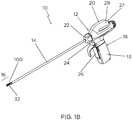
- Ultrasonic surgical instrument 10 generally includes a handle assembly 12, an elongated body portion 14, and a tool assembly 16.
- Tool assembly 16 includes a blade member 32 and a clamp member or jaw member 100.
- Handle assembly 12 supports a battery assembly 18 and an ultrasonic transducer and generator assembly ("TAG") 20, and includes a rotatable nozzle 22, an activation button 24, and a clamp trigger 26.
- Battery assembly 18 and TAG 20 are each releasably secured to handle assembly 12 to facilitate disposal of the entire device, with the exception of battery assembly 18 and TAG 20.
- any or all of the components of ultrasonic surgical instrument 10 may be configured as disposable single-use components or sterilizable multi-use components.
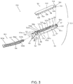
- Elongated body portion 14 of ultrasonic surgical instrument 10 includes a waveguide 30 which extends distally from handle assembly 12 to tool assembly 16. A distal portion of waveguide 30 defines blade member 32 of tool assembly 16. A proximal portion of waveguide 30 is configured to engage TAG 20.
- Elongated body portion 14 of ultrasonic surgical instrument 10 further includes an isolation tube 36 positioned about waveguide 30 to prevent the transfer of ultrasonic energy from waveguide 30 to an inner support tube 42 of elongated body portion 14.
- Waveguide 30 and inner support tube 42 are rotatably coupled to rotatable nozzle 22 such that rotation of nozzle 22 effects corresponding rotation of inner support tube 42 and waveguide 30.
- Elongated body portion 14 further includes an actuator tube 66 coupled to inner support tube 42 and configured to rotate upon rotation of nozzle 22.
- Inner support tube 42 of elongated body portion 14 is positioned about isolation tube 36 and includes a distal end having a pair of spaced clamp support arms 52.
- Spaced clamp support arms 52 are configured to pivotally engage pivot members 114 ( FIG. 3 ) formed on jaw member 100 of tool assembly 16 to enable pivoting of jaw member 100 between an open position ( FIG. 1A ), in which jaw member 100 is spaced from blade member 32, and a closed position ( FIG. 1B ), in which jaw member 100 is approximated relative to blade member 32.
- Jaw member 100 is moved between the open and closed positions in response to actuation of clamp trigger 26, as detailed below.
- Outer actuator tube 66 of elongated body portion 14 is slidably supported about inner support tube 42 (although actuator tube 66 may alternatively be slidably disposed within support tube 42) and is operably coupled to jaw member 100 such that jaw member 100 is pivoted from the open position ( FIG. 1A ) to the closed position ( FIG. 1B ) as actuator tube 66 is slid about inner support tube 42.
- Actuator tube 66 is operably coupled with rotatable nozzle 22 such that outer actuator tube 66 is rotatably secured to, and slidable relative to, rotatable nozzle 22.
- a proximal portion of outer actuator tube 66 is operably coupled with a drive mechanism 80 of handle assembly 12, as detailed below.
- Handle assembly 12 includes drive mechanism 80 supported therein for linear movement relative to handle assembly 12.
- Handle assembly 12 also includes the aforementioned clamp trigger 26, which is operably coupled with drive mechanism 80 such that, in use, when clamping trigger 26 is compressed towards battery assembly 18 ( FIG. 1B ), outer actuator tube 66 is slid about support tube 42 (in a distal-to-proximal or proximal-to-distal direction) to pivot jaw member 100 from the open position to the closed position in relation to blade member 32.
- Battery assembly 18 is connected to a lower end of handle assembly 12 to define a fixed handgrip portion of handle assembly 12 and includes an outer housing 13.
- TAG 20 includes a generator 27 and an ultrasonic transducer (not explicitly shown).
- Generator 27 includes an outer housing 29.
- Other suitable configurations, both cordless and tethered, for providing power and ultrasonic energy, are also contemplated.
- battery assembly 18 and TAG 20 are attached to handle assembly 12 and waveguide 30, respectively, and ultrasonic surgical instrument 10 is activated
- battery assembly 18 provides power to generator 27 of TAG 20 which, in turn, generates an AC signal to drive the ultrasonic transducer of TAG 20.
- the ultrasonic transducer in turn, converts the AC signal into high frequency mechanical motion.
- This high frequency mechanical motion produced by the ultrasonic transducer is transmitted to blade member 32 via waveguide 30 for application of such ultrasonic energy to tissue adjacent to or clamped between blade member 32 and jaw member 100 of tool assembly 16 to treat the tissue.
- Jaw member 100 configured for use with a surgical instrument, for example, ultrasonic surgical instrument 10 described above, is illustrated.
- Jaw member 100 generally includes a support base 110, a jaw liner 130, and an elongated plate 160.
- Support base 110 of jaw member 100 has a relatively rigid construction to provide integrity to jaw member 100 such that jaw member 100 can apply pressure to tissue when tool assembly 16 is in the clamped configuration ( FIG. 1B ).
- Support base 110 may be fabricated from a metal-containing material, for example, steel, or any other suitable material, and may be machined, stamped, metal injection molded, or formed via any other suitable process.
- Support base 110 has a generally elongated configuration and defines a central longitudinal axis "X-X.” It is contemplated that support base 110 may have a curvilinear configuration wherein at least a portion of support base 110 curves laterally off of central longitudinal axis "X-X,” or a linear configuration along the central longitudinal axis "X-X.” Support base 110 has a proximal portion 110a and a distal portion 110b. Proximal portion 110a of support base 110 has a pair of spaced-apart, proximally extending flanges 112a, 112b.
- Flanges 112a, 112b each have a connector, for example, a boss 114, configured for pivotable receipt in a correspondingly shaped recess (not explicitly shown) defined in spaced clamp support arms 52 (see FIG. 2 ) of ultrasonic surgical instrument 10.
- a connector for example, a boss 114
- jaw member 100 is pivotable relative to blade member 32 of ultrasonic surgical instrument 10 to selectively clamp tissue between jaw member 100 and blade member 32 (see FIGS. 1A and 1B ).
- Support base 110 of jaw member 100 defines a cavity 116 therein that extends longitudinally along proximal and distal portions 110a, 110b thereof. Cavity 116 has closed distal and proximal ends and, thus, as detailed below, jaw insert 130 is inserted into support base 110 from an outer surface 129 of support base 110 (further from blade member 32 of ultrasonic surgical instrument 10 as compared to inner surface 124 of support base 110). This at least partial "drop-in" configuration facilitates assembly, particularly with respect to curved jaw members 100. Cavity 116 extends through inner surface 124 of support base 110, a thickness of support base 110, and outer surface 129 of support base 110. Cavity 116 is configured for receipt of jaw liner 130 and plate 160, as will be described in detail below.
- Support base 110 includes first and second side walls 123a, 123b surrounding cavity 116 on either side thereof, and a stepped portion 118 extending from first and second side walls 123a, 123b inwardly into cavity 116.
- First and second side walls 123a, 123b are formed with one another at a rounded distal end portion 110c of support base 110.
- first and second side walls 123a, 123b may be coupled to one another at the distal end portion 110c of support base 110 via a suitable connecting structure rather than being monolithically formed with one another.
- Stepped portion 118 extends inwardly from first and second side walls 123a, 123b, as noted above. While each of the first and second side walls 123a, 123b has a stepped portion 118, for the purposes of brevity, only the stepped portion 118 extending from first side wall 123a will be described herein.
- Stepped portion 118 defines a first ledge 118a and a second ledge 118b, each of which having planar surfaces 120a, 120b oriented towards outer surface 129 of support base 110.
- First and second ledges 118a, 118b each extend generally longitudinally between the proximal and distal portions 110a, 110b of the support base 110 and are curvilinear similarly as support base 110.
- first ledge 118a of stepped portion 118 is disposed closer to inner surface 124 of support base 110 than second ledge 118b and protrudes from second ledge 118b further inwardly into cavity 116.
- first ledge 118a protrudes a first distance "D1" from the first side wall 123a and the second ledge 118b protrudes a second distance "D2" from the first side wall 123a, wherein "D1" is greater than "D2.”
- Second ledge 118b of stepped portion 118 includes a bridge 119 located at proximal portion 110a of support base 110 and which extends transversely between first and second side walls 123a, 123b of support base 110.
- Bridge 119 of second ledge 118b interconnects the second ledge 118b of first side wall 123a with the second ledge (not explicitly shown) of second side wall 123b thus forming one continuous second ledge 118b that spans the first and second side walls 123a, 123b.
- Bridge 119 further serves to close off and define the proximal end of cavity 116.
- Outer surface 129 of support base 110 has a first extension or overhang 122a that extends from first side wall 123a of support base 110 over second ledge 118b to define an inner groove 126 between second ledge 118b and outer surface 129.
- Outer surface 129 of support base 110 has a second extension or overhang 122b that extends from second side wall 123b of support base 110 over the second ledge 118b of the stepped portion 118 on second side wall 123b.
- Inner groove 126 is dimensioned for slidable receipt of plate 160, in a proximal-to-distal direction, such that lateral sides 162, 164 of plate 160 are captured within the respective inner grooves 126 of first and second side walls 123a, 123b of support base 110.
- Distal portion 110b of support base 110 defines a longitudinally-extending notch 128 therein dimensioned for receipt of a distal portion of jaw liner 130.
- jaw liner 130 of jaw member 100 is fabricated from a compliant material that allows blade member 32 of ultrasonic surgical instrument 10 (see FIG. 2 ) to vibrate while in contact therewith without causing damage to blade member 32 or other components of ultrasonic surgical instrument 10, and without compromising the hold on tissue grasped therebetween.
- Jaw liner 130 is configured to be situated in support base 110 such that blade member 32 makes contact with jaw liner 130 rather than support base 110 when tool assembly 16 is in the clamped condition ( FIG. 1B ).
- Jaw liner 130 may be fabricated from a plastic, for example, polytetrafluoroethylene, polyetheretherketone, perfluoroalkoxy, and/or fluorinated ethylene propylene.
- jaw liner 130 may be fabricated from any suitable compliable material, for example, soft metals, rubbers, or the like.
- jaw linear 130 may be fabricated from a metal.
- Jaw liner 130 of jaw member 100 includes an elongate body 132 and a projection 140 disposed thereon.
- Elongate body 132 has a rectangular configuration and includes a proximal portion 132a and a distal portion 132b. In some embodiments, elongate body 132 may assume any suitable shape, such as, for example, triangular, square, elliptical, or the like.
- Elongate body 132 of jaw liner 130 is configured for receipt within cavity 116 of support base 110 and has an outer surface 134 and an inner tissue-contacting surface 136.
- Tissue-contacting surface 136 of jaw liner 130 has a plurality of teeth 138 disposed along a length of jaw liner 130. Teeth 138 have a trapezoidal shape, but it is contemplated that teeth 138 may assume and suitable shape that functions to aid in grasping or holding tissue between jaw member 100 and blade member 32 ( FIG. 2 ).
- Projection 140 of jaw liner 130 has an elliptical configuration and is disposed on outer surface 136 of elongate body 132.
- projection 140 of jaw liner 130 may be integrally connected to outer surface 136 or a periphery of elongate body 132, or may be monolithically formed with outer surface 136 or the periphery of elongate body 132.
- Projection 140 has a peripheral edge 144 that extends laterally outward from opposing lateral sides of elongate body 132 and proximal portion 132a of elongate body 132, but is recessed proximally from a distal tip 132c of elongate body 132.
- peripheral edge 144 of projection 140 is configured to be disposed on planar surface 120a of first ledge 118a of support base 110 while distal tip 132c of elongate body 132 is configured to be disposed in notch 128 defined in distal portion 110b of support base 110.
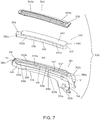
- elongated plate 160 of jaw member 100 has a proximal portion 160a and a distal portion 160b.
- Proximal portion 160a of plate 160 is configured to be disposed on second ledge 118b of support base 110 and to cover jaw liner 130 when jaw liner 130 is received within cavity 116 of support base 110.
- Plate 160 has opposing lateral sides 162, 164 that are dimensioned for receipt within inner grooves 126 of respective first and second side walls 123a, 123b of support base 110.
- Overhangs 122a, 122b of outer surface 129 of support base 110 maintain plate 160 on second ledge 118b of support base 110, thereby preventing plate 160 from falling out of an outwardly-facing opening 117 of cavity 116 of support base 110.
- Proximal portion 160a of plate 160 has a greater width than projection 140 of jaw liner 130 such that jaw liner 130 is dimensioned to be passed through outwardly-facing opening 117 of support base 110 while plate 160 is not.
- jaw liner 130 is inserted into cavity 116 of support base 110 via outwardly-facing opening 117 thereof in an outer-to-inner direction (relative to outer and inner surfaces 129, 124 of support base 110) such that peripheral edge 144 of projection 140 of jaw liner 130 is positioned on first ledge 118a of support base 110.
- distal tip 132c of elongated body 132 of jaw liner 110 is tucked into notch 128 of support base 110.
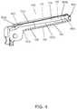
- Tissue-contacting surface 136 of elongated body 132 of jaw liner 130 protrudes from inner surface 124 of support base 110 upon seating peripheral edge 144 of projection 140 of jaw liner 130 on first ledge 118a of support base 110.
- Peripheral edge 144 of projection 140 of jaw liner 130 abuts an inwardly-facing edge of distal end 110c of support base 110 to prevent jaw liner 130 from sliding distally relative to support base 110.
- an under surface of peripheral edge 144 of projection 140 of jaw liner 130 abuts planar surface 120a of first ledge 118a of support base 110 to prevent jaw liner 130 from moving out of cavity 116 through inner surface 124 of support base 110, and opposing lateral sides of peripheral edge 144 of projection 140 of jaw liner 130 abut second ledges 118b of respective first and second side walls 123a, 123b to prevent side-to-side movement of jaw liner 130 within cavity 116 of support base 110.
- jaw liner 130 is substantially unconstrained from withdrawal from cavity 116 via outwardly-facing opening 117 thereof (other than the constraint of distal tip 132c of elongated body 132 of jaw liner 110 being tucked into notch 128 of support base 110).
- plate 160 With jaw liner 130 disposed within cavity 116 of support base 110, plate 160 is slid distally into cavity 116 of support base 110 to position the lateral sides 162, 164 of plate 160 within respective inner grooves 126 of first and second side walls 123a, 123b of support base 110. Distal movement of plate 160 is continued until shoulders 166a, 166b on respective lateral sides 162, 164 of plate 160 abut a distal end of inner grooves 126, and a proximal end of plate 160 is seated on bridge 119 of second ledge 118b.
- plate 160 With plate 160 positioned over jaw liner 130 and captured between overhangs 122a, 122b of support base 110 and second ledge 118b of support base 110, plate 160 prevents jaw liner 130 from backing out of support base 110 through outwardly-facing opening 117 of support base 110.
- Plate 160, jaw liner 130, and support base 110 may be further configured such that plate 160 retains jaw liner 130 in position via compression-fit.
- a jaw overmold (not shown) may be applied over plate 160 to aid in securing plate 160 to support base 110.
- plate 160 may be welded or otherwise permanently secured to support base 110 at select locations about the periphery of plate 160 or around the entire periphery thereof.
- Jaw member 200 generally includes a support base 210, a jaw liner 230, and an elongated plate 260.
- Support base 210 of jaw member 200 has a relatively rigid construction to provide integrity to jaw member 200 such that jaw member 200 can apply pressure to tissue when tool assembly 16 is in the clamped configuration ( FIG. 1B ).
- Support base 210 may be fabricated from a metal-containing material, for example, steel, or any other suitable material, and may be machined, stamped, metal injection molded, or formed via any other suitable process.
- Support base 210 has a generally elongated configuration and defines a central longitudinal axis "X-X.” It is contemplated that support base 210 may have a curvilinear configuration wherein at least a portion of support base 210 curves laterally off of central longitudinal axis "X-X,” or a linear configuration along the central longitudinal axis "X-X.” Support base 210 has a proximal portion 210a and a distal portion 210b. Proximal portion 210a of support base 210 has a pair of spaced-apart, proximally extending flanges 212a, 212b.
- Flanges 212a, 212b each have a connector, for example, a boss 214 configured for pivotable receipt in a correspondingly shaped recess (not explicitly shown) defined in spaced clamp support arms 52 (see FIG. 2 ) of ultrasonic surgical instrument 10.
- a connector for example, a boss 214 configured for pivotable receipt in a correspondingly shaped recess (not explicitly shown) defined in spaced clamp support arms 52 (see FIG. 2 ) of ultrasonic surgical instrument 10.
- flanges 212a, 212b of support base 210 are coupled to spaced clamp support arms 52 of ultrasonic surgical instrument 10 (see FIG. 2 )
- jaw member 200 is pivotable relative to blade member 32 of ultrasonic surgical instrument 10 to selectively clamp tissue between jaw member 200 and blade member 32 (see FIGS. 1A and 1B ).
- Support base 210 of jaw member 200 defines a cavity 216 therein that extends longitudinally along proximal and distal portions 210a, 210b thereof.
- Cavity 216 has closed distal and proximal ends, such that jaw insert 230 is received in cavity 216 via outwardly-facing opening 217 defined in support base 210 from an outer surface 229 of support base 210 (further from blade member 32 of ultrasonic surgical instrument 10 as compared to an inner surface 224 of support base 210).
- This at least partial "drop-in" configuration facilitates assembly, particularly with respect to curved jaw member 100.
- Cavity 216 extends through inner surface 224 of support base 210, a thickness of support base 210, and outer surface 229 of support base 210.
- Cavity 216 is configured for receipt of jaw liner 230 and plate 260, as will be described in detail below.
- Support base 210 includes first and second side walls 223a, 223b surrounding cavity 216 on either side thereof, and a stepped portion 218 extending from first and second side walls 223a, 223b inwardly into cavity 216.
- First and second side walls 223a, 223b are formed with one another at a rounded distal end portion 210c of support base 210 and are attached to one another via a transversely-extending bridge 221 located at proximal portion 210a of support base 210.
- first and second side walls 223a, 223b may be coupled to one another, via a suitable connecting structure, rather than being monolithically formed with one another. Bridge serves to close off and define the proximal end of cavity 216.
- Stepped portion 218 of support base 210 extends inwardly from first and second side walls 223a, 223b, as noted above. While each of the first and second side walls 223a, 223b of support base 210 has a stepped portion 218, for the purposes of brevity, only the stepped portion 218 extending from first side wall 223a will be described herein.
- Stepped portion 218 includes a first ledge 218a and a second ledge 218b, each of which having planar surfaces 220a, 220b that are oriented towards outer surface 229 of support base 210.
- First and second ledges 218a, 218b each extend generally longitudinally between the proximal and distal portions 210a, 210b of the support base 210 and are curvilinear similarly as support base 210.
- First ledge 218a of stepped portion 218 is disposed closer to the inner surface 224 of support base 210 than second ledge 218b and protrudes from second ledge 218b further inwardly into cavity 216.
- first ledge 218a protrudes a first distance "D1" from the first side wall 223a and the second ledge 218b protrudes a second distance "D2" from the first side wall 223b, wherein "D1" is greater than “D2.”
- Second ledge 218b of stepped portion 218 includes an arcuate bridge 219 located at distal portion 210b of support base 210 and which extends between first and second side walls 223a, 223b of support base 210.
- Bridge 219 of second ledge 218b interconnects the second ledge 218b of first side wall 223a with the second ledge 218b of second side wall 223b.
- Bridge 219 further serves to close off and define the distal end of cavity 216.
- Distal portion 210b of support base 210 defines a longitudinally-extending notch 228 therein dimensioned for receipt of a distal portion of jaw liner 230.
- jaw liner 230 of jaw member 200 is similar to jaw liner 130 described above with reference to FIGS. 3 and 4 .
- jaw liner 230 of jaw member 200 includes an elongate body 232 and a projection 240 disposed thereon.
- Elongate body 232 has a rectangular configuration and includes a proximal portion 232a and a distal portion 232b.
- Elongate body 232 of jaw liner 230 is configured for receipt within cavity 216 of support base 210 and has an outer surface 234 and an inner tissue-contacting surface 236.
- Tissue-contacting surface 236 of jaw liner 230 has a plurality of teeth 238 disposed along a length of jaw liner 230.
- Projection 240 of jaw liner 230 has an elliptical configuration and is disposed on outer surface 234 of elongate body 232.
- Projection 240 has a peripheral edge 244 that extends laterally outward from opposing lateral sides of elongate body 232 and proximal portion 232a of elongate body 232, but is recessed proximally from a distal tip 232c of elongate body 232.
- peripheral edge 244 of projection 240 is configured to be disposed on planar surface 220a of first ledge 218a of support base 210 while distal tip 232c of elongate body 232 is configured to be disposed within, e.g., tucked into, notch 228 defined in distal portion 210b of support base 210.
- elongated plate 260 of jaw member 200 has a proximal portion 260a and a distal portion 260b.
- proximal and distal portions 260a, 260b of plate 260 is configured to be disposed on second ledge 218b of support base 210 and to cover jaw liner 230 when jaw liner 230 is received within cavity 216 of support base 210.
- support base 230 instead of support base 230 having the overhangs 122a, 122b of support base 110 of FIGS. 3 and 4 to prevent plate 260 from falling out of outwardly-facing opening 217 of cavity 216, plate 260 is dimensioned for compression fit in cavity 216 of support base 210.
- Proximal portion 260a of plate 260 has a greater width than projection 240 of jaw liner 230 such that jaw liner 230 is dimensioned to be passed over second ledge 218b and onto first ledge 218a while plate 260 cannot pass over second ledge 218b.
- jaw liner 230 is inserted into cavity 216 of support base 210 via outwardly-facing opening 217 thereof in an outer-to-inner direction (relative to outer and inner surfaces 229, 224 of support base 210) such that peripheral edge 244 of projection 240 of jaw liner 230 is positioned on first ledge 218a of support base 210.
- distal tip 232c of elongated body 232 of jaw liner 210 is tucked into notch 228 of support base 210.
- Tissue-contacting surface 236 of elongated body 232 of jaw liner 230 protrudes from inner surface 224 of support base 210 upon seating peripheral edge 244 of projection 240 of jaw liner 230 on first ledge 218a of support base 210.
- Peripheral edge 244 of projection 240 of jaw liner 230 abuts an inwardly-facing edge of distal end portion 210c of support base 210, thereby preventing jaw liner 230 from sliding distally relative to support base 210.
- First ledge 218a of support base 210 prevents jaw liner 230 from moving out of cavity 216 through inner surface 224 of support base 210.
- jaw liner 230 Upon positioning jaw liner 230 in cavity 216 of support base 210, an under surface of peripheral edge 244 of projection 240 of jaw liner 230 abuts planar surface 220a of first ledge 218a of support base 210 to prevent jaw liner 230 from moving out of cavity 216 through inner surface 224 of support base 210, and opposing lateral sides of peripheral edge 244 of projection 240 of jaw liner 230 abut second ledges 218b of respective first and second side walls 223a, 223b to prevent side-to-side movement of jaw liner 230 within cavity 216 of support base 210.
- jaw liner 230 is substantially constrained from withdrawn from cavity 216 via outwardly-facing opening 217 thereof.
- plate 260 With jaw liner 230 disposed within cavity 216 of support base 210, plate 260 is inserted into cavity 216 of support base 210 via outer opening 217 of support base 210 to position lateral sides 262, 264 of plate 260 on second ledge 218b of support base 210. A threshold amount of a downward-oriented force is applied to plate 260 to form a compression fit between plate 260 and cavity 216 of support base 210.
- an adhesive may be applied to an undersurface of plate 260 or planar surface 220b of second ledge 218b to secure plate 260 to support base 210.
- a jaw overmold (not shown) may be applied over plate 260 to aid in securing plate 260 to support base 210.
- plate 260 With plate 260 positioned over jaw liner 230 and fixed to support base 210, plate 260 prevents jaw liner 230 from backing out of support base 210 through outer opening 217 of support base 210. Additionally, since cavity 216 of support base 210 is closed at its proximal end due to bridge 221 of support base 210, plate 260 and jaw insert 230 are each inhibited from backing out proximally from cavity 216 of support base 210. Additionally or alternatively, plate 260 may be welded or otherwise permanently secured to support base 210 at select locations about the periphery of plate 260 or around the entire periphery thereof. Once jaw member 200 is manufactured, jaw member 200 may be pivotably connected to elongated body portion 14 ( FIG. 2 ) of ultrasonic surgical instrument 10.
- Jaw member 300 generally includes a support base 310, a jaw liner 330, and an elongated plate 360.
- Support base 310 of jaw member 300 has a relatively rigid construction to provide integrity to jaw member 300 such that jaw member 300 can apply pressure to tissue when tool assembly 16 is in the clamped configuration ( FIG. 1B ).
- Support base 310 may be fabricated from a metal-containing material, for example, steel, or any other suitable material, and may be machined, stamped, metal injection molded, or formed via any other suitable process.
- Support base 310 has a generally elongated configuration and defines a central longitudinal axis "X-X.” It is contemplated that support base 310 may have a curvilinear configuration wherein at least a portion of support base 310 curves laterally off of central longitudinal axis "X-X,” or a linear configuration along the central longitudinal axis "X-X.” Support base 310 has a proximal portion 310a and a distal portion 310b. Proximal portion 310a of support base 310 has a pair of spaced-apart, proximally extending flanges 312a, 312b.
- Flanges 312a, 312b each have a connector, for example, a boss 314 configured for pivotable receipt in a correspondingly shaped recess (not explicitly shown) defined in spaced clamp support arms 52 (see FIG. 2 ) of ultrasonic surgical instrument 10.
- a connector for example, a boss 314 configured for pivotable receipt in a correspondingly shaped recess (not explicitly shown) defined in spaced clamp support arms 52 (see FIG. 2 ) of ultrasonic surgical instrument 10.
- flanges 312a, 312b of support base 310 are coupled to spaced clamp support arms 52 of ultrasonic surgical instrument 10 (see FIG. 2 )
- jaw member 300 is pivotable relative to blade member 32 of ultrasonic surgical instrument 10 to selectively clamp tissue between jaw member 300 and blade member 32 (see FIGS. 1A and 1B ).
- Support base 310 of jaw member 300 defines a cavity or cavity 316 therein that extends longitudinally along proximal and distal portions 310a, 310b thereof. Cavity 316 has a closed distal end 316b and an open proximal end 316a. As detailed below, jaw insert 330 may be inserted into support base 310 from an outer surface 329 of support base 310 (further from blade member 32 of ultrasonic surgical instrument 10 as compared to an inner surface 324 of support base 310). This at least partial "drop-in" configuration facilitates assembly, particularly with respect to curved jaw member 100. Cavity 116 extends through inner surface 324 of support base 310, a thickness of support base 310, and outer surface 329 of support base 310. Cavity 316 is configured for receipt of jaw liner 330 and plate 360, as will be described in detail below.
- Support base 310 includes first and second side walls 323a, 323b surrounding cavity 316 on either side thereof, and a stepped portion 318 extending from first and second side walls 323a, 323b inwardly into cavity 316.
- First and second side walls 323a, 323b are formed with one another at a rounded distal end portion 310c of support base 310 and transversely-spaced from one another at a proximal end of support base 310.
- first and second side walls 323a, 323b may be coupled to one another, via a suitable connecting structure, rather than being monolithically formed with one another.
- Stepped portion 318 extends inwardly from first and second side walls 323a, 323b, as noted above. While each of first and second side walls 323a, 323b of support base 310 has a stepped portion 318 extending therefrom, for the purposes of brevity, only the stepped portion 318 extending from first side wall 323a will be described herein.
- Stepped portion 318 defines a first ledge 318a and a second ledge 318b, each of which having planar surfaces 320a, 320b that are oriented towards outer surface 329 of support base 310.
- First and second ledges 318a, 318b each extend generally longitudinally between the proximal and distal portions 310a, 310b of the support base 310 and are curvilinear similarly as support base 310.
- First ledge 318a of stepped portion 318 is disposed closer to the inner surface 324 of support base 310 than second ledge 318b and protrudes from second ledge 318b further inwardly into cavity 316.
- first ledge 318a protrudes a first distance "D1" from the first side wall 323a and the second ledge 318b protrudes a second distance "D2" from the first side wall 323a, wherein “D1" is greater than “D2.”
- Second ledge 318b includes an arcuate bridge 319 located at distal end portion 310c of support base 310 and which extends between first and second side walls 323a, 323b of support base 310.
- Bridge 319 of second ledge 318b interconnects the second ledge 318b of first side wall 323a with the second ledge 318b of second side wall 323b to support a distal portion 360b of plate 360 thereon.
- Distal portion 310b of support base 310 defines a longitudinally-extending notch 328 therein dimensioned for receipt of a distal portion of jaw liner 130.
- Bridge 319 further serves to close off and define the closed distal end of cavity 316.
- jaw liner 330 of jaw member 300 is similar to jaw liners 130, 230 described above with reference to FIGS. 3-6 .
- Jaw liner 330 of jaw member 300 includes an elongate body 332 and a projection 340 disposed thereon.
- Elongate body 332 has a rectangular configuration and includes a proximal portion 332a and a distal portion 332b.
- Elongate body 332 of jaw liner 330 is configured for receipt within cavity 316 of support base 310 and has an outer surface 334 and an inner tissue-contacting surface 336.
- Tissue-contacting surface 336 of jaw liner 330 has a plurality of teeth 338 disposed along a length of jaw liner 330.
- Projection 340 of jaw liner 330 has an elliptical configuration and is disposed on outer surface 336 of elongate body 332.
- Projection 340 has a peripheral edge 344 that extends laterally outward from opposing lateral sides of elongate body 332 and proximal portion 332a of elongate body 332, but is recessed proximally from a distal tip 332c of elongate body 332.
- the peripheral edge 344 of projection 340 is configured to be disposed on planar surface 320a of first ledge 318a of support base 310 while distal tip 332c of elongate body 332 is configured to be disposed in notch 328 defined in distal portion 310b of support base 310.
- elongated plate 360 of jaw member 300 has a proximal portion 360a and a distal portion 360b.
- proximal and distal portions 360a, 360b of plate 360 is configured to be disposed on second ledge 318b of support base 310 and to cover jaw liner 330 when jaw liner 330 is received within cavity 316 of support base 310.
- support base 310 having the overhangs 122a,122b of support base 130 of FIGS. 3 and 4 to prevent plate 360 from falling out of an outwardly-facing opening 317 of cavity 316
- plate 360 is dimensioned for compression fit in cavity 316 of support base 310.
- Proximal portion 360a of plate 360 has a greater width than projection 340 of jaw liner 330 such that jaw liner 330 is dimensioned to be passed over second ledge 318b and onto first ledge 318a while plate 360 cannot pass over second ledge 318b.
- Plate 360 is different from plate 260 of FIGS. 5 and 6 by having a tab 370 extending from proximal portion 360a thereof.
- Tab 370 extends substantially perpendicularly from an outer surface of plate 360.
- Tab 370 is configured to abut a proximal end of jaw liner 330 to prevent jaw liner 330 from sliding proximally out of open proximal end 316a of cavity 316.
- jaw liner 330 is inserted into cavity 316 of support base 310 via outwardly-facing opening 317 thereof in an outer-to-inner direction (relative to outer and inner surfaces 329, 324 of support base 310) to position peripheral edge 344 of projection 340 of jaw liner 330 on first ledge 318a of support base 310.
- distal tip 332c of elongated body 323 of jaw liner 310 is tucked into notch 328 of support base 310.
- Tissue-contacting surface 336 of elongated body 332 of jaw liner 330 protrudes from inner surface 324 of support base 310 upon seating peripheral edge 344 of projection 340 of jaw liner 330 on first ledge 318a of support base 310.
- Peripheral edge 344 of projection 340 of jaw liner 330 abuts an inwardly-facing edge of distal end portion 310c of support base 310 to prevent jaw liner 330 from sliding distally relative to support base 310.
- jaw liner 330 Upon positioning jaw liner 330 in cavity 316 of support base 310, an under surface of peripheral edge 344 of projection 344 of jaw liner 330 abuts planar surface 320a of first ledge 318a of support base 310 to prevent jaw liner 330 from moving out of cavity 316 through inner surface 324 of support base 310, and opposing lateral sides of peripheral edge 344 of projection 340 of jaw liner 330 abut second ledges 318b of respective first and second side walls 323a, 323b to prevent side-to-side movement of jaw liner 130. At this point, jaw liner 330 is substantially unconstrained from withdrawal from cavity 316 via outwardly-facing opening 317 thereof.
- plate 360 is inserted into cavity 316 of support base 310 by moving plate 360 distally into cavity 316 via open proximal end 316a of cavity 316 of support base 310 to position the lateral sides of plate 360 on second ledge 318b of support base 310.
- plate 360 may be inserted into cavity 316 of support base 310 via outwardly-facing opening 317 thereof in an outer-to-inner direction rather than in a proximal-to-distal direction.
- a threshold amount of a distally-oriented force is applied to plate 360 to form a compression fit between plate 360 and cavity 316 of support base 310.
- an adhesive may be applied to an undersurface of plate 360 or planar surface 320b of second ledge 320a to secure plate 360 to support base 310.
- a jaw overmold (not shown) may be applied over plate 360 to aid in securing plate 360 to support base 310.
- plate 360 may be welded or otherwise permanently secured to support base 310 at select locations about the periphery of plate 360 or around the entire periphery thereof.
- jaw member 300 With plate 360 positioned over jaw liner 330 and fixed to support base 310, plate 360 prevents jaw liner 330 from backing out of support base 310 through outwardly-facing opening 317 of support base 310. Additionally, tab 370 of plate 360 is in abutment with proximal end of jaw liner 330 to prevent jaw liner 330 from backing out proximally from support base 310 via open proximal end 316a of cavity 316.
- jaw member 300 Once jaw member 300 is assembled or manufactured, jaw member 300 may be pivotably connected to elongated body portion 14 ( FIG. 2 ) of ultrasonic surgical instrument 10.
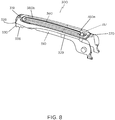
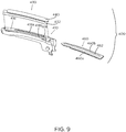
- FIGS. 9 and 10 another embodiment of a jaw member 400 is illustrated, similar to the jaw member 100 shown in FIGS. 3 and 4 . Thus, only those features of jaw member 400 necessary to elucidate differences between jaw member 400 and jaw member 100 will be described.
- Jaw member 400 generally includes a support base 410, a jaw liner 430, and an elongated plate 460.
- the support base 410 of jaw member 400 defines a cavity 416 therein dimensioned for receipt of jaw insert 430.
- Support base 410 has an extension or overhang 422 that defines an inner groove 426.
- Inner groove 426 is dimensioned for slidable receipt of plate 460, in a proximal-to-distal direction.
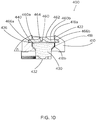
- Support base 410 has a stepped portion 418 that defines a first ledge 418a and a second ledge 418b, similar to stepped portion 118 of jaw member 100 ( FIGS. 3 and 4 ). However, instead of ledges 418a, 418b extending substantially parallel relative to one another as ledges 118a, 118b of support base 110 ( FIGS. 3 and 4 ), second ledge 418b of support base 410 extends at an oblique angle relative to first ledge 418a of support base 410, which runs substantially parallel to a longitudinal axis defined by support base 410. As such, the cavity 416 of support base 410 has a wedge-shaped configuration as illustrated in FIG. 10 .
- projection 440 of jaw liner 430 instead of projection 440 of jaw liner 430 extending substantially perpendicularly from elongate body 432 of jaw liner 430 as with projection 110 of jaw liner 130 ( FIGS. 3 and 4 ), projection 440 of jaw liner 430 flares outwardly from elongate body 432 of jaw liner 430 at an oblique angle, e.g., between about 10 and 80 degrees, and in some embodiments, between about 35 and 55 degrees.
- projection 440 of jaw liner 430 is configured to complimentarily engage the slanted second ledge 418b of support base 410 when the jaw liner 430 is received within the cavity 416 of the support base 410, e.g., via a "drop-in" approach.
- Plate 460 of jaw member 400 includes a spine 462 extending along a central longitudinal axis thereof.
- the spine 462 defines a longitudinally-extending gap 464 that divides plate 460 into two longitudinal half-sections 460a, 460b.
- the gap 464 allows half-sections 460a, 460b to flex toward one another about the spine 462 during insertion of plate 460 into cavity 416.
- plate 460 may be assembled to support base 410 using a "drop-in” approach (similarly as with the assembly of jaw liner 430 with support base 410) rather than sliding plate 460 longitudinally into cavity 416.
- Plate 460 may define tapered lateral edges 466a, 466b on each of half-sections 460a, 460b to facilitate entry and/or exit of plate 460 from support base 410.
- plate 460 may be assembled to support base 410 via sliding cover 460 longitudinally into groove 426, rather than being "dropped-in.”
Abstract
Description
- The present disclosure relates to jaw members of surgical instruments and, more particularly, to jaw members of ultrasonic surgical instruments.
- Some surgical instruments have an end effector including at least one jaw member configured to treat or manipulate tissue of a patient. An example of such a surgical instrument is an ultrasonic surgical instrument that utilizes ultrasonic energy, i.e., ultrasonic vibrations, to treat tissue. More specifically, an ultrasonic surgical instrument that utilizes mechanical vibration energy transmitted at ultrasonic frequencies to coagulate, cauterize, fuse, seal, cut, desiccate, fulgurate, or otherwise treat tissue. Such an ultrasonic surgical instrument is configured to transmit ultrasonic energy produced by a generator and transducer assembly along a waveguide to an end effector that is spaced-apart from the generator and transducer assembly. The end effector includes a blade and a jaw member configured to clamp and treat tissue between the blade and the jaw member.
- Typically, the vibrations induced in the blade will be transferred to the jaw member, which may damage the jaw member or other components of the surgical instrument. Additionally, the high frequency vibrations may generate high temperatures in the jaw member, which may also damage the jaw member.
- Accordingly, a need exists for an improved jaw member constructed to withstand the high frequency vibrations generated by the ultrasonic surgical instrument and/or to withstand the high temperatures produced thereby. Further, a need exists to provide such a jaw member that is efficient and not overly difficult or expensive to manufacture.
- In one aspect of the present disclosure, an embodiment of a jaw member for use with a surgical instrument is provided. The jaw member includes a support base, a jaw liner, and an elongated body. The support base has a proximal portion configured to be pivotably coupled to a surgical instrument, and a distal portion. The support base defines a cavity therein that extends longitudinally between the proximal and distal portions. The support base includes a stepped portion formed therein, which defines a first ledge and a second ledge. The jaw liner includes an elongate body configured for receipt in the cavity of the support base, and a projection extending radially outward from a periphery of the elongate body. The projection is configured to be seated on the first ledge of the support base. The elongated plate is configured to be seated on the second ledge of the support base adjacent the jaw liner to secure the jaw liner relative to the support base.
- In some embodiments, the stepped portion may be disposed on both sides of the cavity of the support base and extend longitudinally therealong.
- It is contemplated that the support base may include a first side wall defining a first side of the cavity and a second side wall defining a second side of the cavity. Each of the first and second ledges of the support base may protrude laterally from the first and second side walls inwardly into the cavity.
- It is envisioned that the first ledge may protrude a first distance laterally from the first and second side walls and the second ledge may protrude a second distance laterally from the first and second side walls. The first distance is greater than the second distance.
- In some embodiments, each of the first and second ledges of the support base may extend along a length of the support base.
- It is contemplated that the support base may have an outer surface that extends over the second ledge such that the plate is configured to be captured between the outer surface of the support base and the second ledge of the support base.
- It is envisioned that the jaw liner may have a tissue-contacting surface formed on the elongate body of the jaw liner. The tissue-contacting surface of the jaw liner may be fabricated from plastic, for example, polytetrafluoroethylene, polyetheretherketone, perfluoroalkoxy, and/or fluorinated ethylene propylene. The tissue-contacting surface may have a plurality of teeth disposed along a length of the jaw liner. The support base may have an inner surface, and the tissue-contacting surface of the jaw liner may project from the inner surface of the support base.
- In some embodiments, the plate may have a proximal portion and a tab extending from the proximal portion. The tab of the plate may be configured to abut a proximal portion of the projection of the jaw liner to prevent proximal movement of the jaw liner relative to the support base.
- It is contemplated that the cavity of the support base may be closed via a bridge inhibiting slidable insertion of the jaw liner into the cavity while permitting slidable insertion of the elongated plate into the cavity.
- It is envisioned that the cavity of the support base may have a closed proximal end such that proximal movement of the jaw liner relative to the support base is inhibited.
- In yet another aspect of the present disclosure, a surgical instrument is provided and includes a handle assembly, an elongated body portion extending distally from the handle assembly, and a tool assembly operably coupled to the elongated body portion. The tool assembly includes a blade member and a jaw member. The jaw member includes a support base, a jaw liner, and an elongated plate. The support base has a proximal portion pivotably coupled to the elongated body portion, and a distal portion. The support base defines a cavity therein that extends longitudinally between the proximal and distal portions. The support base includes a stepped portion formed therein, which defines a first ledge and a second ledge. The jaw liner includes an elongate body received in the cavity of the support base and a projection extending radially outward from a periphery of the elongate body and seated on the first ledge of the support base. The elongated plate is seated on the second ledge of the support base adjacent the jaw liner to secure the jaw liner relative to the support base. The jaw member is movable relative to the blade member between an open position, in which the jaw liner of the jaw member is spaced from the blade member, and a closed position, in which the jaw liner of the jaw member is approximated relative to the blade member.
- Further details and aspects of exemplary embodiments of the present disclosure are described in more detail below with reference to the appended figures.
- As used herein, the terms parallel and perpendicular are understood to include relative configurations that are substantially parallel and substantially perpendicular up to about + or - 10 degrees from true parallel and true perpendicular.
- The above and other aspects and features of the present disclosure will become more apparent in view of the following detailed description when taken in conjunction with the accompanying drawings, wherein:
-
FIG. 1A is a perspective view of an illustrative embodiment of an ultrasonic surgical instrument provided in accordance with the present disclosure, including a tool assembly thereof illustrated in an open condition; -
FIG. 1B is a perspective view of the ultrasonic surgical instrument ofFIG. 1A , wherein the tool assembly is illustrated in a closed, clamping condition; -
FIG. 2 is an exploded, perspective view of a shaft, a waveguide, and the tool assembly of the ultrasonic surgical instrument ofFIG. 1A ; -
FIG. 3 is an exploded, perspective view of a jaw member for use with the ultrasonic surgical instrument ofFIG. 1A ; -
FIG. 4 is a perspective view of the jaw member ofFIG. 3 in an assembled state; -
FIG. 5 is an exploded, perspective view of another jaw member for use with the ultrasonic surgical instrument ofFIG. 1A ; -
FIG. 6 is a perspective view of the jaw member ofFIG. 5 in an assembled state; -
FIG. 7 is an exploded, perspective view of another jaw member for use with the ultrasonic surgical instrument ofFIG. 1A ; -
FIG. 8 is a perspective view of the jaw member ofFIG. 7 in an assembled state; -
FIG. 9 is an exploded, perspective view of another jaw member for use with the ultrasonic surgical instrument ofFIG. 1A ; and -
FIG. 10 is a transverse cross-sectional view of the jaw member ofFIG. 9 in an assembled state. - Embodiments of the presently disclosed jaw members, surgical instruments including such jaw members, and methods of manufacturing thereof, are described in detail with reference to the drawings, in which like reference numerals designate identical or corresponding elements in each of the several views. As used herein the term "distal" refers to that portion of the surgical instrument and/or jaw member thereof, that is closer to the patient, while the term "proximal" refers to that portion of the surgical instrument and/or jaw member, that is farther from the patient.
- For purposes of illustration only, the following detailed description of a surgical instrument will be limited to describing unique jaw members as incorporated on an embodiment of an ultrasonic
surgical instrument 10 as shown generally inFIGS. 1A ,1B , and2 . The jaw members include a jaw support base and a jaw liner fixed within the jaw support base by an elongated plate that inhibits detachment of the jaw liner from the jaw support base during use of ultrasonicsurgical instrument 10. It is contemplated that the various jaw members detailed herein may also be used with other surgical instruments other than ultrasonicsurgical instrument 10, for example, any suitable type of surgical instrument that functions to clamp and/or treat tissue, such as any suitable electromechanical surgical instrument or electrosurgical instrument. - Ultrasonic
surgical instrument 10 generally includes ahandle assembly 12, anelongated body portion 14, and atool assembly 16.Tool assembly 16 includes ablade member 32 and a clamp member orjaw member 100. Handleassembly 12 supports abattery assembly 18 and an ultrasonic transducer and generator assembly ("TAG") 20, and includes arotatable nozzle 22, anactivation button 24, and aclamp trigger 26.Battery assembly 18 andTAG 20 are each releasably secured to handleassembly 12 to facilitate disposal of the entire device, with the exception ofbattery assembly 18 andTAG 20. However, it is contemplated that any or all of the components of ultrasonicsurgical instrument 10 may be configured as disposable single-use components or sterilizable multi-use components. -
Elongated body portion 14 of ultrasonicsurgical instrument 10 includes awaveguide 30 which extends distally fromhandle assembly 12 totool assembly 16. A distal portion ofwaveguide 30 definesblade member 32 oftool assembly 16. A proximal portion ofwaveguide 30 is configured to engageTAG 20.Elongated body portion 14 of ultrasonicsurgical instrument 10 further includes anisolation tube 36 positioned aboutwaveguide 30 to prevent the transfer of ultrasonic energy fromwaveguide 30 to aninner support tube 42 ofelongated body portion 14.Waveguide 30 andinner support tube 42 are rotatably coupled torotatable nozzle 22 such that rotation ofnozzle 22 effects corresponding rotation ofinner support tube 42 andwaveguide 30.Elongated body portion 14 further includes anactuator tube 66 coupled toinner support tube 42 and configured to rotate upon rotation ofnozzle 22. -
Inner support tube 42 ofelongated body portion 14 is positioned aboutisolation tube 36 and includes a distal end having a pair of spacedclamp support arms 52. Spacedclamp support arms 52 are configured to pivotally engage pivot members 114 (FIG. 3 ) formed onjaw member 100 oftool assembly 16 to enable pivoting ofjaw member 100 between an open position (FIG. 1A ), in whichjaw member 100 is spaced fromblade member 32, and a closed position (FIG. 1B ), in whichjaw member 100 is approximated relative toblade member 32.Jaw member 100 is moved between the open and closed positions in response to actuation ofclamp trigger 26, as detailed below. -
Outer actuator tube 66 ofelongated body portion 14 is slidably supported about inner support tube 42 (althoughactuator tube 66 may alternatively be slidably disposed within support tube 42) and is operably coupled tojaw member 100 such thatjaw member 100 is pivoted from the open position (FIG. 1A ) to the closed position (FIG. 1B ) asactuator tube 66 is slid aboutinner support tube 42.Actuator tube 66 is operably coupled withrotatable nozzle 22 such thatouter actuator tube 66 is rotatably secured to, and slidable relative to,rotatable nozzle 22. Further, a proximal portion ofouter actuator tube 66 is operably coupled with a drive mechanism 80 ofhandle assembly 12, as detailed below. - Handle
assembly 12 includes drive mechanism 80 supported therein for linear movement relative to handleassembly 12. Handleassembly 12 also includes theaforementioned clamp trigger 26, which is operably coupled with drive mechanism 80 such that, in use, when clampingtrigger 26 is compressed towards battery assembly 18 (FIG. 1B ),outer actuator tube 66 is slid about support tube 42 (in a distal-to-proximal or proximal-to-distal direction) to pivotjaw member 100 from the open position to the closed position in relation toblade member 32. -
Battery assembly 18 is connected to a lower end ofhandle assembly 12 to define a fixed handgrip portion ofhandle assembly 12 and includes anouter housing 13.TAG 20 includes agenerator 27 and an ultrasonic transducer (not explicitly shown).Generator 27 includes anouter housing 29. Other suitable configurations, both cordless and tethered, for providing power and ultrasonic energy, are also contemplated. - In general, in use, when
battery assembly 18 andTAG 20 are attached to handleassembly 12 andwaveguide 30, respectively, and ultrasonicsurgical instrument 10 is activated,battery assembly 18 provides power togenerator 27 ofTAG 20 which, in turn, generates an AC signal to drive the ultrasonic transducer ofTAG 20. The ultrasonic transducer, in turn, converts the AC signal into high frequency mechanical motion. This high frequency mechanical motion produced by the ultrasonic transducer is transmitted toblade member 32 viawaveguide 30 for application of such ultrasonic energy to tissue adjacent to or clamped betweenblade member 32 andjaw member 100 oftool assembly 16 to treat the tissue. - With reference to
FIGS. 3 and4 , an embodiment of ajaw member 100 configured for use with a surgical instrument, for example, ultrasonicsurgical instrument 10 described above, is illustrated.Jaw member 100 generally includes asupport base 110, ajaw liner 130, and anelongated plate 160.Support base 110 ofjaw member 100 has a relatively rigid construction to provide integrity tojaw member 100 such thatjaw member 100 can apply pressure to tissue whentool assembly 16 is in the clamped configuration (FIG. 1B ).Support base 110 may be fabricated from a metal-containing material, for example, steel, or any other suitable material, and may be machined, stamped, metal injection molded, or formed via any other suitable process. -
Support base 110 has a generally elongated configuration and defines a central longitudinal axis "X-X." It is contemplated thatsupport base 110 may have a curvilinear configuration wherein at least a portion ofsupport base 110 curves laterally off of central longitudinal axis "X-X," or a linear configuration along the central longitudinal axis "X-X."Support base 110 has aproximal portion 110a and adistal portion 110b.Proximal portion 110a ofsupport base 110 has a pair of spaced-apart, proximally extendingflanges Flanges boss 114, configured for pivotable receipt in a correspondingly shaped recess (not explicitly shown) defined in spaced clamp support arms 52 (seeFIG. 2 ) of ultrasonicsurgical instrument 10. As such, whenflanges support base 110 are coupled to spacedclamp support arms 52 of ultrasonic surgical instrument 10 (seeFIG. 2 ),jaw member 100 is pivotable relative toblade member 32 of ultrasonicsurgical instrument 10 to selectively clamp tissue betweenjaw member 100 and blade member 32 (seeFIGS. 1A and1B ). -
Support base 110 ofjaw member 100 defines acavity 116 therein that extends longitudinally along proximal anddistal portions Cavity 116 has closed distal and proximal ends and, thus, as detailed below,jaw insert 130 is inserted intosupport base 110 from anouter surface 129 of support base 110 (further fromblade member 32 of ultrasonicsurgical instrument 10 as compared toinner surface 124 of support base 110). This at least partial "drop-in" configuration facilitates assembly, particularly with respect tocurved jaw members 100.Cavity 116 extends throughinner surface 124 ofsupport base 110, a thickness ofsupport base 110, andouter surface 129 ofsupport base 110.Cavity 116 is configured for receipt ofjaw liner 130 andplate 160, as will be described in detail below. -
Support base 110 includes first andsecond side walls cavity 116 on either side thereof, and a steppedportion 118 extending from first andsecond side walls cavity 116. First andsecond side walls distal end portion 110c ofsupport base 110. In some embodiments, first andsecond side walls distal end portion 110c ofsupport base 110 via a suitable connecting structure rather than being monolithically formed with one another. - Stepped
portion 118 extends inwardly from first andsecond side walls second side walls portion 118, for the purposes of brevity, only the steppedportion 118 extending fromfirst side wall 123a will be described herein. Steppedportion 118 defines afirst ledge 118a and asecond ledge 118b, each of which havingplanar surfaces outer surface 129 ofsupport base 110. First andsecond ledges distal portions support base 110 and are curvilinear similarly assupport base 110. - The
first ledge 118a of steppedportion 118 is disposed closer toinner surface 124 ofsupport base 110 thansecond ledge 118b and protrudes fromsecond ledge 118b further inwardly intocavity 116. In particular,first ledge 118a protrudes a first distance "D1" from thefirst side wall 123a and thesecond ledge 118b protrudes a second distance "D2" from thefirst side wall 123a, wherein "D1" is greater than "D2." As such,first ledge 118a protrudes a distance "D3 = D1 - D2" fromsecond ledge 118b to support aprojection 140 ofjaw insert 130 thereon, as will be described below. -
Second ledge 118b of steppedportion 118 includes abridge 119 located atproximal portion 110a ofsupport base 110 and which extends transversely between first andsecond side walls support base 110.Bridge 119 ofsecond ledge 118b interconnects thesecond ledge 118b offirst side wall 123a with the second ledge (not explicitly shown) ofsecond side wall 123b thus forming one continuoussecond ledge 118b that spans the first andsecond side walls Bridge 119 further serves to close off and define the proximal end ofcavity 116. -
Outer surface 129 ofsupport base 110 has a first extension oroverhang 122a that extends fromfirst side wall 123a ofsupport base 110 oversecond ledge 118b to define aninner groove 126 betweensecond ledge 118b andouter surface 129.Outer surface 129 ofsupport base 110 has a second extension oroverhang 122b that extends fromsecond side wall 123b ofsupport base 110 over thesecond ledge 118b of the steppedportion 118 onsecond side wall 123b.Inner groove 126 is dimensioned for slidable receipt ofplate 160, in a proximal-to-distal direction, such thatlateral sides plate 160 are captured within the respectiveinner grooves 126 of first andsecond side walls support base 110.Distal portion 110b ofsupport base 110 defines a longitudinally-extendingnotch 128 therein dimensioned for receipt of a distal portion ofjaw liner 130. - With continued reference to
FIGS. 3 and4 ,jaw liner 130 ofjaw member 100 is fabricated from a compliant material that allowsblade member 32 of ultrasonic surgical instrument 10 (seeFIG. 2 ) to vibrate while in contact therewith without causing damage toblade member 32 or other components of ultrasonicsurgical instrument 10, and without compromising the hold on tissue grasped therebetween.Jaw liner 130 is configured to be situated insupport base 110 such thatblade member 32 makes contact withjaw liner 130 rather thansupport base 110 whentool assembly 16 is in the clamped condition (FIG. 1B ).Jaw liner 130 may be fabricated from a plastic, for example, polytetrafluoroethylene, polyetheretherketone, perfluoroalkoxy, and/or fluorinated ethylene propylene. In some embodiments,jaw liner 130 may be fabricated from any suitable compliable material, for example, soft metals, rubbers, or the like. In other embodiments, jaw linear 130 may be fabricated from a metal. -
Jaw liner 130 ofjaw member 100 includes anelongate body 132 and aprojection 140 disposed thereon.Elongate body 132 has a rectangular configuration and includes aproximal portion 132a and adistal portion 132b. In some embodiments,elongate body 132 may assume any suitable shape, such as, for example, triangular, square, elliptical, or the like.Elongate body 132 ofjaw liner 130 is configured for receipt withincavity 116 ofsupport base 110 and has anouter surface 134 and an inner tissue-contactingsurface 136. Tissue-contactingsurface 136 ofjaw liner 130 has a plurality ofteeth 138 disposed along a length ofjaw liner 130.Teeth 138 have a trapezoidal shape, but it is contemplated thatteeth 138 may assume and suitable shape that functions to aid in grasping or holding tissue betweenjaw member 100 and blade member 32 (FIG. 2 ). -
Projection 140 ofjaw liner 130 has an elliptical configuration and is disposed onouter surface 136 ofelongate body 132. In some embodiments,projection 140 ofjaw liner 130 may be integrally connected toouter surface 136 or a periphery ofelongate body 132, or may be monolithically formed withouter surface 136 or the periphery ofelongate body 132.Projection 140 has aperipheral edge 144 that extends laterally outward from opposing lateral sides ofelongate body 132 andproximal portion 132a ofelongate body 132, but is recessed proximally from adistal tip 132c ofelongate body 132. As such, theperipheral edge 144 ofprojection 140 is configured to be disposed onplanar surface 120a offirst ledge 118a ofsupport base 110 whiledistal tip 132c ofelongate body 132 is configured to be disposed innotch 128 defined indistal portion 110b ofsupport base 110. - With continued reference to
FIGS. 3 and4 , elongatedplate 160 ofjaw member 100 has aproximal portion 160a and adistal portion 160b.Proximal portion 160a ofplate 160 is configured to be disposed onsecond ledge 118b ofsupport base 110 and to coverjaw liner 130 whenjaw liner 130 is received withincavity 116 ofsupport base 110.Plate 160 has opposinglateral sides inner grooves 126 of respective first andsecond side walls support base 110.Overhangs outer surface 129 ofsupport base 110 maintainplate 160 onsecond ledge 118b ofsupport base 110, thereby preventingplate 160 from falling out of an outwardly-facingopening 117 ofcavity 116 ofsupport base 110.Proximal portion 160a ofplate 160 has a greater width thanprojection 140 ofjaw liner 130 such thatjaw liner 130 is dimensioned to be passed through outwardly-facingopening 117 ofsupport base 110 whileplate 160 is not. - To assemble or manufacture
jaw member 100,jaw liner 130 is inserted intocavity 116 ofsupport base 110 via outwardly-facingopening 117 thereof in an outer-to-inner direction (relative to outer andinner surfaces peripheral edge 144 ofprojection 140 ofjaw liner 130 is positioned onfirst ledge 118a ofsupport base 110. During such insertion,distal tip 132c ofelongated body 132 ofjaw liner 110 is tucked intonotch 128 ofsupport base 110. Tissue-contactingsurface 136 ofelongated body 132 ofjaw liner 130 protrudes frominner surface 124 ofsupport base 110 upon seatingperipheral edge 144 ofprojection 140 ofjaw liner 130 onfirst ledge 118a ofsupport base 110.Peripheral edge 144 ofprojection 140 ofjaw liner 130 abuts an inwardly-facing edge ofdistal end 110c ofsupport base 110 to preventjaw liner 130 from sliding distally relative to supportbase 110. Upon positioningjaw liner 130 incavity 116 ofsupport base 110, an under surface ofperipheral edge 144 ofprojection 140 ofjaw liner 130 abutsplanar surface 120a offirst ledge 118a ofsupport base 110 to preventjaw liner 130 from moving out ofcavity 116 throughinner surface 124 ofsupport base 110, and opposing lateral sides ofperipheral edge 144 ofprojection 140 ofjaw liner 130 abutsecond ledges 118b of respective first andsecond side walls jaw liner 130 withincavity 116 ofsupport base 110. At this point,jaw liner 130 is substantially unconstrained from withdrawal fromcavity 116 via outwardly-facingopening 117 thereof (other than the constraint ofdistal tip 132c ofelongated body 132 ofjaw liner 110 being tucked intonotch 128 of support base 110). - With
jaw liner 130 disposed withincavity 116 ofsupport base 110,plate 160 is slid distally intocavity 116 ofsupport base 110 to position thelateral sides plate 160 within respectiveinner grooves 126 of first andsecond side walls support base 110. Distal movement ofplate 160 is continued untilshoulders lateral sides plate 160 abut a distal end ofinner grooves 126, and a proximal end ofplate 160 is seated onbridge 119 ofsecond ledge 118b. Withplate 160 positioned overjaw liner 130 and captured betweenoverhangs support base 110 andsecond ledge 118b ofsupport base 110,plate 160 preventsjaw liner 130 from backing out ofsupport base 110 through outwardly-facingopening 117 ofsupport base 110.Plate 160,jaw liner 130, andsupport base 110 may be further configured such thatplate 160 retainsjaw liner 130 in position via compression-fit. In some embodiments, a jaw overmold (not shown) may be applied overplate 160 to aid in securingplate 160 to supportbase 110. Additionally or alternatively,plate 160 may be welded or otherwise permanently secured to supportbase 110 at select locations about the periphery ofplate 160 or around the entire periphery thereof. Oncejaw member 100 is manufactured,jaw member 100 may be pivotably connected to elongated body portion 14 (FIG. 2 ) of ultrasonicsurgical instrument 10. - With reference to
FIGS. 5 and6 , another embodiment of ajaw member 200 configured for use with ultrasonicsurgical instrument 10 is illustrated.Jaw member 200 generally includes asupport base 210, ajaw liner 230, and anelongated plate 260. -
Support base 210 ofjaw member 200 has a relatively rigid construction to provide integrity tojaw member 200 such thatjaw member 200 can apply pressure to tissue whentool assembly 16 is in the clamped configuration (FIG. 1B ).Support base 210 may be fabricated from a metal-containing material, for example, steel, or any other suitable material, and may be machined, stamped, metal injection molded, or formed via any other suitable process. -
Support base 210 has a generally elongated configuration and defines a central longitudinal axis "X-X." It is contemplated thatsupport base 210 may have a curvilinear configuration wherein at least a portion ofsupport base 210 curves laterally off of central longitudinal axis "X-X," or a linear configuration along the central longitudinal axis "X-X."Support base 210 has aproximal portion 210a and adistal portion 210b.Proximal portion 210a ofsupport base 210 has a pair of spaced-apart, proximally extendingflanges Flanges boss 214 configured for pivotable receipt in a correspondingly shaped recess (not explicitly shown) defined in spaced clamp support arms 52 (seeFIG. 2 ) of ultrasonicsurgical instrument 10. As such, whenflanges support base 210 are coupled to spacedclamp support arms 52 of ultrasonic surgical instrument 10 (seeFIG. 2 ),jaw member 200 is pivotable relative toblade member 32 of ultrasonicsurgical instrument 10 to selectively clamp tissue betweenjaw member 200 and blade member 32 (seeFIGS. 1A and1B ). -
Support base 210 ofjaw member 200 defines acavity 216 therein that extends longitudinally along proximal anddistal portions Cavity 216 has closed distal and proximal ends, such thatjaw insert 230 is received incavity 216 via outwardly-facingopening 217 defined insupport base 210 from anouter surface 229 of support base 210 (further fromblade member 32 of ultrasonicsurgical instrument 10 as compared to aninner surface 224 of support base 210). This at least partial "drop-in" configuration facilitates assembly, particularly with respect tocurved jaw member 100.Cavity 216 extends throughinner surface 224 ofsupport base 210, a thickness ofsupport base 210, andouter surface 229 ofsupport base 210.Cavity 216 is configured for receipt ofjaw liner 230 andplate 260, as will be described in detail below. -
Support base 210 includes first andsecond side walls cavity 216 on either side thereof, and a steppedportion 218 extending from first andsecond side walls cavity 216. First andsecond side walls distal end portion 210c ofsupport base 210 and are attached to one another via a transversely-extendingbridge 221 located atproximal portion 210a ofsupport base 210. In some embodiments, first andsecond side walls cavity 216. - Stepped
portion 218 ofsupport base 210 extends inwardly from first andsecond side walls second side walls support base 210 has a steppedportion 218, for the purposes of brevity, only the steppedportion 218 extending fromfirst side wall 223a will be described herein. Steppedportion 218 includes afirst ledge 218a and asecond ledge 218b, each of which havingplanar surfaces outer surface 229 ofsupport base 210. First andsecond ledges distal portions support base 210 and are curvilinear similarly assupport base 210. -
First ledge 218a of steppedportion 218 is disposed closer to theinner surface 224 ofsupport base 210 thansecond ledge 218b and protrudes fromsecond ledge 218b further inwardly intocavity 216. In particular,first ledge 218a protrudes a first distance "D1" from thefirst side wall 223a and thesecond ledge 218b protrudes a second distance "D2" from thefirst side wall 223b, wherein "D1" is greater than "D2." As such,first ledge 218a protrudes a distance "D3 = D1 - D2" fromsecond ledge 218b to support aprojection 240 ofjaw insert 230 thereon, as will be described below. -
Second ledge 218b of steppedportion 218 includes anarcuate bridge 219 located atdistal portion 210b ofsupport base 210 and which extends between first andsecond side walls support base 210.Bridge 219 ofsecond ledge 218b interconnects thesecond ledge 218b offirst side wall 223a with thesecond ledge 218b ofsecond side wall 223b.Bridge 219 further serves to close off and define the distal end ofcavity 216.Distal portion 210b ofsupport base 210 defines a longitudinally-extendingnotch 228 therein dimensioned for receipt of a distal portion ofjaw liner 230. - With continued reference to
FIGS. 5 and6 ,jaw liner 230 ofjaw member 200 is similar tojaw liner 130 described above with reference toFIGS. 3 and4 . In particular,jaw liner 230 ofjaw member 200 includes anelongate body 232 and aprojection 240 disposed thereon.Elongate body 232 has a rectangular configuration and includes aproximal portion 232a and adistal portion 232b.Elongate body 232 ofjaw liner 230 is configured for receipt withincavity 216 ofsupport base 210 and has anouter surface 234 and an inner tissue-contactingsurface 236. Tissue-contactingsurface 236 ofjaw liner 230 has a plurality ofteeth 238 disposed along a length ofjaw liner 230. -
Projection 240 ofjaw liner 230 has an elliptical configuration and is disposed onouter surface 234 ofelongate body 232.Projection 240 has aperipheral edge 244 that extends laterally outward from opposing lateral sides ofelongate body 232 andproximal portion 232a ofelongate body 232, but is recessed proximally from adistal tip 232c ofelongate body 232. As such, theperipheral edge 244 ofprojection 240 is configured to be disposed onplanar surface 220a offirst ledge 218a ofsupport base 210 whiledistal tip 232c ofelongate body 232 is configured to be disposed within, e.g., tucked into, notch 228 defined indistal portion 210b ofsupport base 210. - With continued reference to
FIGS. 5 and6 , elongatedplate 260 ofjaw member 200 has aproximal portion 260a and adistal portion 260b. Each of proximal anddistal portions plate 260 is configured to be disposed onsecond ledge 218b ofsupport base 210 and to coverjaw liner 230 whenjaw liner 230 is received withincavity 216 ofsupport base 210. Instead ofsupport base 230 having theoverhangs support base 110 ofFIGS. 3 and4 to preventplate 260 from falling out of outwardly-facingopening 217 ofcavity 216,plate 260 is dimensioned for compression fit incavity 216 ofsupport base 210.Proximal portion 260a ofplate 260 has a greater width thanprojection 240 ofjaw liner 230 such thatjaw liner 230 is dimensioned to be passed oversecond ledge 218b and ontofirst ledge 218a whileplate 260 cannot pass oversecond ledge 218b. - To assemble or manufacture
jaw member 200,jaw liner 230 is inserted intocavity 216 ofsupport base 210 via outwardly-facingopening 217 thereof in an outer-to-inner direction (relative to outer andinner surfaces peripheral edge 244 ofprojection 240 ofjaw liner 230 is positioned onfirst ledge 218a ofsupport base 210. During such insertion,distal tip 232c ofelongated body 232 ofjaw liner 210 is tucked intonotch 228 ofsupport base 210. Tissue-contactingsurface 236 ofelongated body 232 ofjaw liner 230 protrudes frominner surface 224 ofsupport base 210 upon seatingperipheral edge 244 ofprojection 240 ofjaw liner 230 onfirst ledge 218a ofsupport base 210.Peripheral edge 244 ofprojection 240 ofjaw liner 230 abuts an inwardly-facing edge ofdistal end portion 210c ofsupport base 210, thereby preventingjaw liner 230 from sliding distally relative to supportbase 210.First ledge 218a ofsupport base 210 preventsjaw liner 230 from moving out ofcavity 216 throughinner surface 224 ofsupport base 210. Upon positioningjaw liner 230 incavity 216 ofsupport base 210, an under surface ofperipheral edge 244 ofprojection 240 ofjaw liner 230 abutsplanar surface 220a offirst ledge 218a ofsupport base 210 to preventjaw liner 230 from moving out ofcavity 216 throughinner surface 224 ofsupport base 210, and opposing lateral sides ofperipheral edge 244 ofprojection 240 ofjaw liner 230 abutsecond ledges 218b of respective first andsecond side walls jaw liner 230 withincavity 216 ofsupport base 210. At this point,jaw liner 230 is substantially constrained from withdrawn fromcavity 216 via outwardly-facingopening 217 thereof. - With
jaw liner 230 disposed withincavity 216 ofsupport base 210,plate 260 is inserted intocavity 216 ofsupport base 210 viaouter opening 217 ofsupport base 210 to positionlateral sides plate 260 onsecond ledge 218b ofsupport base 210. A threshold amount of a downward-oriented force is applied toplate 260 to form a compression fit betweenplate 260 andcavity 216 ofsupport base 210. In some embodiments, instead of or in addition to forming a compression fit, an adhesive may be applied to an undersurface ofplate 260 orplanar surface 220b ofsecond ledge 218b to secureplate 260 to supportbase 210. In other embodiments, a jaw overmold (not shown) may be applied overplate 260 to aid in securingplate 260 to supportbase 210. - With
plate 260 positioned overjaw liner 230 and fixed to supportbase 210,plate 260 preventsjaw liner 230 from backing out ofsupport base 210 throughouter opening 217 ofsupport base 210. Additionally, sincecavity 216 ofsupport base 210 is closed at its proximal end due tobridge 221 ofsupport base 210,plate 260 andjaw insert 230 are each inhibited from backing out proximally fromcavity 216 ofsupport base 210. Additionally or alternatively,plate 260 may be welded or otherwise permanently secured to supportbase 210 at select locations about the periphery ofplate 260 or around the entire periphery thereof. Oncejaw member 200 is manufactured,jaw member 200 may be pivotably connected to elongated body portion 14 (FIG. 2 ) of ultrasonicsurgical instrument 10. - With reference to
FIGS. 7 and8 , another embodiment of ajaw member 300 configured for use with ultrasonicsurgical instrument 10 is illustrated.Jaw member 300 generally includes asupport base 310, ajaw liner 330, and anelongated plate 360. -
Support base 310 ofjaw member 300 has a relatively rigid construction to provide integrity tojaw member 300 such thatjaw member 300 can apply pressure to tissue whentool assembly 16 is in the clamped configuration (FIG. 1B ).Support base 310 may be fabricated from a metal-containing material, for example, steel, or any other suitable material, and may be machined, stamped, metal injection molded, or formed via any other suitable process. -
Support base 310 has a generally elongated configuration and defines a central longitudinal axis "X-X." It is contemplated thatsupport base 310 may have a curvilinear configuration wherein at least a portion ofsupport base 310 curves laterally off of central longitudinal axis "X-X," or a linear configuration along the central longitudinal axis "X-X."Support base 310 has aproximal portion 310a and adistal portion 310b.Proximal portion 310a ofsupport base 310 has a pair of spaced-apart, proximally extendingflanges Flanges boss 314 configured for pivotable receipt in a correspondingly shaped recess (not explicitly shown) defined in spaced clamp support arms 52 (seeFIG. 2 ) of ultrasonicsurgical instrument 10. As such, whenflanges support base 310 are coupled to spacedclamp support arms 52 of ultrasonic surgical instrument 10 (seeFIG. 2 ),jaw member 300 is pivotable relative toblade member 32 of ultrasonicsurgical instrument 10 to selectively clamp tissue betweenjaw member 300 and blade member 32 (seeFIGS. 1A and1B ). -
Support base 310 ofjaw member 300 defines a cavity orcavity 316 therein that extends longitudinally along proximal anddistal portions Cavity 316 has a closeddistal end 316b and an openproximal end 316a. As detailed below,jaw insert 330 may be inserted intosupport base 310 from anouter surface 329 of support base 310 (further fromblade member 32 of ultrasonicsurgical instrument 10 as compared to aninner surface 324 of support base 310). This at least partial "drop-in" configuration facilitates assembly, particularly with respect tocurved jaw member 100.Cavity 116 extends throughinner surface 324 ofsupport base 310, a thickness ofsupport base 310, andouter surface 329 ofsupport base 310.Cavity 316 is configured for receipt ofjaw liner 330 andplate 360, as will be described in detail below. -
Support base 310 includes first andsecond side walls 323a, 323b surroundingcavity 316 on either side thereof, and a steppedportion 318 extending from first andsecond side walls 323a, 323b inwardly intocavity 316. First andsecond side walls 323a, 323b are formed with one another at a roundeddistal end portion 310c ofsupport base 310 and transversely-spaced from one another at a proximal end ofsupport base 310. In some embodiments, first andsecond side walls 323a, 323b may be coupled to one another, via a suitable connecting structure, rather than being monolithically formed with one another. - Stepped
portion 318 extends inwardly from first andsecond side walls 323a, 323b, as noted above. While each of first andsecond side walls 323a, 323b ofsupport base 310 has a steppedportion 318 extending therefrom, for the purposes of brevity, only the steppedportion 318 extending from first side wall 323a will be described herein. Steppedportion 318 defines afirst ledge 318a and asecond ledge 318b, each of which havingplanar surfaces outer surface 329 ofsupport base 310. First andsecond ledges distal portions support base 310 and are curvilinear similarly assupport base 310. -
First ledge 318a of steppedportion 318 is disposed closer to theinner surface 324 ofsupport base 310 thansecond ledge 318b and protrudes fromsecond ledge 318b further inwardly intocavity 316. In particular,first ledge 318a protrudes a first distance "D1" from the first side wall 323a and thesecond ledge 318b protrudes a second distance "D2" from the first side wall 323a, wherein "D1" is greater than "D2." As such,first ledge 318a protrudes a distance "D3 = D1 - D2" fromsecond ledge 318b to support aprojection 340 ofjaw insert 330 thereon, as will be described below. -
Second ledge 318b includes anarcuate bridge 319 located atdistal end portion 310c ofsupport base 310 and which extends between first andsecond side walls 323a, 323b ofsupport base 310.Bridge 319 ofsecond ledge 318b interconnects thesecond ledge 318b of first side wall 323a with thesecond ledge 318b ofsecond side wall 323b to support adistal portion 360b ofplate 360 thereon.Distal portion 310b ofsupport base 310 defines a longitudinally-extendingnotch 328 therein dimensioned for receipt of a distal portion ofjaw liner 130.Bridge 319 further serves to close off and define the closed distal end ofcavity 316. - With continued reference to
FIGS. 7 and8 ,jaw liner 330 ofjaw member 300 is similar tojaw liners FIGS. 3-6 .Jaw liner 330 ofjaw member 300 includes anelongate body 332 and aprojection 340 disposed thereon.Elongate body 332 has a rectangular configuration and includes aproximal portion 332a and adistal portion 332b.Elongate body 332 ofjaw liner 330 is configured for receipt withincavity 316 ofsupport base 310 and has anouter surface 334 and an inner tissue-contactingsurface 336. Tissue-contactingsurface 336 ofjaw liner 330 has a plurality ofteeth 338 disposed along a length ofjaw liner 330. -
Projection 340 ofjaw liner 330 has an elliptical configuration and is disposed onouter surface 336 ofelongate body 332.Projection 340 has aperipheral edge 344 that extends laterally outward from opposing lateral sides ofelongate body 332 andproximal portion 332a ofelongate body 332, but is recessed proximally from adistal tip 332c ofelongate body 332. As such, theperipheral edge 344 ofprojection 340 is configured to be disposed onplanar surface 320a offirst ledge 318a ofsupport base 310 whiledistal tip 332c ofelongate body 332 is configured to be disposed innotch 328 defined indistal portion 310b ofsupport base 310. - With continued reference to
FIGS. 7 and8 , elongatedplate 360 ofjaw member 300 has aproximal portion 360a and adistal portion 360b. Each of proximal anddistal portions plate 360 is configured to be disposed onsecond ledge 318b ofsupport base 310 and to coverjaw liner 330 whenjaw liner 330 is received withincavity 316 ofsupport base 310. Instead ofsupport base 310 having theoverhangs support base 130 ofFIGS. 3 and4 to preventplate 360 from falling out of an outwardly-facingopening 317 ofcavity 316,plate 360 is dimensioned for compression fit incavity 316 ofsupport base 310.Proximal portion 360a ofplate 360 has a greater width thanprojection 340 ofjaw liner 330 such thatjaw liner 330 is dimensioned to be passed oversecond ledge 318b and ontofirst ledge 318a whileplate 360 cannot pass oversecond ledge 318b. -
Plate 360 is different fromplate 260 ofFIGS. 5 and6 by having atab 370 extending fromproximal portion 360a thereof.Tab 370 extends substantially perpendicularly from an outer surface ofplate 360.Tab 370 is configured to abut a proximal end ofjaw liner 330 to preventjaw liner 330 from sliding proximally out of openproximal end 316a ofcavity 316. - To assemble or manufacture
jaw member 300,jaw liner 330 is inserted intocavity 316 ofsupport base 310 via outwardly-facingopening 317 thereof in an outer-to-inner direction (relative to outer andinner surfaces peripheral edge 344 ofprojection 340 ofjaw liner 330 onfirst ledge 318a ofsupport base 310. During such insertion,distal tip 332c of elongated body 323 ofjaw liner 310 is tucked intonotch 328 ofsupport base 310. Tissue-contactingsurface 336 ofelongated body 332 ofjaw liner 330 protrudes frominner surface 324 ofsupport base 310 upon seatingperipheral edge 344 ofprojection 340 ofjaw liner 330 onfirst ledge 318a ofsupport base 310.Peripheral edge 344 ofprojection 340 ofjaw liner 330 abuts an inwardly-facing edge ofdistal end portion 310c ofsupport base 310 to preventjaw liner 330 from sliding distally relative to supportbase 310. Upon positioningjaw liner 330 incavity 316 ofsupport base 310, an under surface ofperipheral edge 344 ofprojection 344 ofjaw liner 330 abutsplanar surface 320a offirst ledge 318a ofsupport base 310 to preventjaw liner 330 from moving out ofcavity 316 throughinner surface 324 ofsupport base 310, and opposing lateral sides ofperipheral edge 344 ofprojection 340 ofjaw liner 330 abutsecond ledges 318b of respective first andsecond side walls 323a, 323b to prevent side-to-side movement ofjaw liner 130. At this point,jaw liner 330 is substantially unconstrained from withdrawal fromcavity 316 via outwardly-facingopening 317 thereof. - With
jaw liner 330 disposed withincavity 316 ofsupport base 310,plate 360 is inserted intocavity 316 ofsupport base 310 by movingplate 360 distally intocavity 316 via openproximal end 316a ofcavity 316 ofsupport base 310 to position the lateral sides ofplate 360 onsecond ledge 318b ofsupport base 310. Alternatively,plate 360 may be inserted intocavity 316 ofsupport base 310 via outwardly-facingopening 317 thereof in an outer-to-inner direction rather than in a proximal-to-distal direction. A threshold amount of a distally-oriented force (alternatively an inner-oriented force) is applied toplate 360 to form a compression fit betweenplate 360 andcavity 316 ofsupport base 310. In some embodiments, instead of or in addition to forming a compression fit, an adhesive may be applied to an undersurface ofplate 360 orplanar surface 320b ofsecond ledge 320a to secureplate 360 to supportbase 310. In other embodiments, a jaw overmold (not shown) may be applied overplate 360 to aid in securingplate 360 to supportbase 310. Additionally or alternatively,plate 360 may be welded or otherwise permanently secured to supportbase 310 at select locations about the periphery ofplate 360 or around the entire periphery thereof. - With
plate 360 positioned overjaw liner 330 and fixed to supportbase 310,plate 360 preventsjaw liner 330 from backing out ofsupport base 310 through outwardly-facingopening 317 ofsupport base 310. Additionally,tab 370 ofplate 360 is in abutment with proximal end ofjaw liner 330 to preventjaw liner 330 from backing out proximally fromsupport base 310 via openproximal end 316a ofcavity 316. Oncejaw member 300 is assembled or manufactured,jaw member 300 may be pivotably connected to elongated body portion 14 (FIG. 2 ) of ultrasonicsurgical instrument 10. - With reference to
FIGS. 9 and10 , another embodiment of ajaw member 400 is illustrated, similar to thejaw member 100 shown inFIGS. 3 and4 . Thus, only those features ofjaw member 400 necessary to elucidate differences betweenjaw member 400 andjaw member 100 will be described. -
Jaw member 400 generally includes asupport base 410, ajaw liner 430, and anelongated plate 460. Thesupport base 410 ofjaw member 400 defines acavity 416 therein dimensioned for receipt ofjaw insert 430.Support base 410 has an extension oroverhang 422 that defines aninner groove 426.Inner groove 426 is dimensioned for slidable receipt ofplate 460, in a proximal-to-distal direction. -
Support base 410 has a steppedportion 418 that defines afirst ledge 418a and asecond ledge 418b, similar to steppedportion 118 of jaw member 100 (FIGS. 3 and4 ). However, instead ofledges ledges FIGS. 3 and4 ),second ledge 418b ofsupport base 410 extends at an oblique angle relative tofirst ledge 418a ofsupport base 410, which runs substantially parallel to a longitudinal axis defined bysupport base 410. As such, thecavity 416 ofsupport base 410 has a wedge-shaped configuration as illustrated inFIG. 10 . Additionally, instead ofprojection 440 ofjaw liner 430 extending substantially perpendicularly fromelongate body 432 ofjaw liner 430 as withprojection 110 of jaw liner 130 (FIGS. 3 and4 ),projection 440 ofjaw liner 430 flares outwardly fromelongate body 432 ofjaw liner 430 at an oblique angle, e.g., between about 10 and 80 degrees, and in some embodiments, between about 35 and 55 degrees. As such,projection 440 ofjaw liner 430 is configured to complimentarily engage the slantedsecond ledge 418b ofsupport base 410 when thejaw liner 430 is received within thecavity 416 of thesupport base 410, e.g., via a "drop-in" approach. -
Plate 460 ofjaw member 400 includes aspine 462 extending along a central longitudinal axis thereof. Thespine 462 defines a longitudinally-extendinggap 464 that dividesplate 460 into two longitudinal half-sections gap 464 allows half-sections spine 462 during insertion ofplate 460 intocavity 416. As such,plate 460 may be assembled to supportbase 410 using a "drop-in" approach (similarly as with the assembly ofjaw liner 430 with support base 410) rather than slidingplate 460 longitudinally intocavity 416.Plate 460 may define taperedlateral edges sections plate 460 fromsupport base 410. In some embodiments,plate 460 may be assembled to supportbase 410 via slidingcover 460 longitudinally intogroove 426, rather than being "dropped-in." - While several embodiments of the disclosure have been shown in the drawings, it is not intended that the disclosure be limited thereto, as it is intended that the disclosure be as broad in scope as the art will allow and that the specification be read likewise. Therefore, the above description should not be construed as limiting, but merely as exemplifications of particular embodiments. Those skilled in the art will envision other modifications within the scope and spirit of the claims appended hereto.
- The invention may be described by reference to the following numbered paragraphs:-
- 1. A jaw member for use with a surgical instrument, the jaw member comprising:
- a support base having a proximal portion configured to be pivotably coupled to a surgical instrument, and a distal portion, the support base defining a cavity therein that extends longitudinally between the proximal and distal portions, the support base including a stepped portion formed therein, the stepped portion defining a first ledge and a second ledge;
- a jaw liner including:
- an elongate body configured for receipt in the cavity of the support base; and
- a projection extending radially outward from a periphery of the elongate body and configured to be seated on the first ledge of the support base; and
- an elongated plate configured to be seated on the second ledge of the support base adjacent the jaw liner to secure the jaw liner relative to the support base.
- 2. The jaw member according to paragraph 1, wherein the stepped portion is disposed on both sides of the cavity and extends longitudinally therealong.
- 3. The jaw member according to paragraph 2, wherein the support base includes:
- a first side wall defining a first side of the cavity; and
- a second side wall defining a second side of the cavity, each of the first and second ledges of the support base protruding laterally from the first and second side walls inwardly into the cavity.
- 4. The jaw member according to paragraph 3, wherein the first ledge protrudes a first distance laterally from the first and second side walls and the second ledge protrudes a second distance laterally from the first and second side walls, the first distance being greater than the second distance.
- 5. The jaw member according to paragraph 1, wherein each of the first and second ledges of the support base extends along a length of the support base.
- 6. The jaw member according to paragraph 1, wherein the support base has an outer surface that extends over the second ledge such that the plate is configured to be captured between the outer surface of the support base and the second ledge of the support base.
- 7. The jaw member according to paragraph 1, wherein the jaw liner has a tissue-contacting surface formed on the elongate body of the jaw liner.
- 8. The jaw member according to paragraph 7, wherein the tissue-contacting surface of the jaw liner is fabricated from plastic.
- 9. The jaw member according to paragraph 8, wherein the plastic is selected from the group consisting of polytetrafluoroethylene, polyetheretherketone, perfluoroalkoxy, and fluorinated ethylene propylene.
- 10. The jaw member according to paragraph 7, wherein the tissue-contacting surface has a plurality of teeth disposed along a length of the jaw liner.
- 11. The jaw member according to paragraph 7, wherein the support base has an inner surface, and the tissue-contacting surface of the jaw liner projects from the inner surface of the support base.
- 12. The jaw member according to paragraph 1, wherein the plate has a proximal portion and a tab extending from the proximal portion, the tab of the plate configured to abut a proximal portion of the projection of the jaw liner to prevent proximal movement of the jaw liner relative to the support base.
- 13. The jaw member according to
paragraph 12, wherein the cavity of the support base is closed via a bridge inhibiting slidable insertion of the jaw liner into the cavity while permitting slidable insertion of the elongated plate into the cavity. - 14. The jaw member according to paragraph 1, wherein the cavity of the support base has a closed proximal end such that proximal movement of the jaw liner relative to the support base is inhibited.
- 15. A surgical instrument, comprising:
- a handle assembly;
- an elongated body portion extending distally from the handle assembly; and
- a tool assembly operably coupled to the elongated body portion and including:
- a blade member; and
- a jaw member including:
- a support base having a proximal portion pivotably coupled to the elongated body portion, and a distal portion, the support base defining a cavity therein that extends longitudinally between the proximal and distal portions, the support base including a stepped portion formed therein, the stepped portion defining a first ledge and a second ledge;
- a jaw liner including:
- an elongate body received in the cavity of the support base; and
- a projection extending radially outward from a periphery of the elongate body and seated on the first ledge of the support base; and
- an elongated plate seated on the second ledge of the support base adjacent the jaw liner to secure the jaw liner relative to the support base, wherein the jaw member is movable relative to the blade member between an open position, in which the jaw liner of the jaw member is spaced from the blade member, and a closed position, in which the jaw liner of the jaw member is approximated relative to the blade member.
- 16. The surgical instrument according to paragraph 15, wherein the stepped portion is disposed on both sides of the cavity and extends longitudinally therealong.
- 17. The surgical instrument according to
paragraph 16, wherein the support base includes:- a first side wall defining a first side of the cavity; and
- a second side wall defining a second side of the cavity, each of the first and second ledges of the support base protruding laterally from the first and second side walls inwardly into the cavity.
- 18. The surgical instrument according to paragraph 17, wherein the first ledge protrudes a first distance laterally from the first and second side walls and the second ledge protrudes a second distance laterally from the first and second side walls, the first distance being greater than the second distance.
- 19. The surgical instrument according to paragraph 15, wherein each of the first and second ledges of the support base extends along a length of the support base.
- 20. The surgical instrument according to paragraph 15, wherein the support base has an outer surface that extends over the second ledge such that the plate is configured to be captured between the outer surface of the support base and the second ledge of the support base.
Claims (15)
- A jaw member for use with a surgical instrument, the jaw member comprising:a support base having a proximal portion configured to be pivotably coupled to a surgical instrument, and a distal portion, the support base defining a cavity therein that extends longitudinally between the proximal and distal portions, the support base including a stepped portion formed therein, the stepped portion defining a first ledge and a second ledge;a jaw liner including:an elongate body configured for receipt in the cavity of the support base; anda projection extending radially outward from a periphery of the elongate body and configured to be seated on the first ledge of the support base; andan elongated plate configured to be seated on the second ledge of the support base adjacent the jaw liner to secure the jaw liner relative to the support base.
- The jaw member according to claim 1, wherein the stepped portion is disposed on both sides of the cavity and extends longitudinally therealong.
- The jaw member according to claim 2, wherein the support base includes:a first side wall defining a first side of the cavity; anda second side wall defining a second side of the cavity, each of the first and second ledges of the support base protruding laterally from the first and second side walls inwardly into the cavity.
- The jaw member according to claim 3, wherein the first ledge protrudes a first distance laterally from the first and second side walls and the second ledge protrudes a second distance laterally from the first and second side walls, the first distance being greater than the second distance.
- The jaw member according to claim 1, wherein each of the first and second ledges of the support base extends along a length of the support base.
- The jaw member according to claim 1, wherein the support base has an outer surface that extends over the second ledge such that the plate is configured to be captured between the outer surface of the support base and the second ledge of the support base.
- The jaw member according to claim 1, wherein the jaw liner has a tissue-contacting surface formed on the elongate body of the jaw liner.
- The jaw member according to claim 7, wherein the tissue-contacting surface of the jaw liner is fabricated from plastic.
- The jaw member according to claim 8, wherein the plastic is selected from the group consisting of polytetrafluoroethylene, polyetheretherketone, perfluoroalkoxy, and fluorinated ethylene propylene.
- The jaw member according to any of claims 7, 8 or 9, wherein the tissue-contacting surface has a plurality of teeth disposed along a length of the jaw liner.
- The jaw member according to any one of claims 7 to 10, wherein the support base has an inner surface, and the tissue-contacting surface of the jaw liner projects from the inner surface of the support base.
- The jaw member according to any preceding claim, wherein the plate has a proximal portion and a tab extending from the proximal portion, the tab of the plate configured to abut a proximal portion of the projection of the jaw liner to prevent proximal movement of the jaw liner relative to the support base.
- The jaw member according to claim 12, wherein the cavity of the support base is closed via a bridge inhibiting slidable insertion of the jaw liner into the cavity while permitting slidable insertion of the elongated plate into the cavity.
- The jaw member according to any preceding claim, wherein the cavity of the support base has a closed proximal end such that proximal movement of the jaw liner relative to the support base is inhibited.
- A surgical instrument, comprising:a handle assembly;an elongated body portion extending distally from the handle assembly; anda tool assembly operably coupled to the elongated body portion and including:a blade member; and a jaw member as claimed in any preceding claimwherein the jaw member is movable relative to the blade member between an open position, in which the jaw liner of the jaw member is spaced from the blade member, and a closed position, in which the jaw liner of the jaw member is approximated relative to the blade member.
Applications Claiming Priority (2)
| Application Number | Priority Date | Filing Date | Title |
|---|---|---|---|
| US201662425314P | 2016-11-22 | 2016-11-22 | |
| US15/800,833 US10987124B2 (en) | 2016-11-22 | 2017-11-01 | Surgical instruments and jaw members thereof |
Publications (2)
| Publication Number | Publication Date |
|---|---|
| EP3323361A1 true EP3323361A1 (en) | 2018-05-23 |
| EP3323361B1 EP3323361B1 (en) | 2020-03-11 |
Family
ID=60421625
Family Applications (1)
| Application Number | Title | Priority Date | Filing Date |
|---|---|---|---|
| EP17202686.6A Active EP3323361B1 (en) | 2016-11-22 | 2017-11-21 | Surgical instruments and jaw members thereof |
Country Status (3)
| Country | Link |
|---|---|
| US (1) | US10987124B2 (en) |
| EP (1) | EP3323361B1 (en) |
| JP (1) | JP6542332B2 (en) |
Families Citing this family (2)
| Publication number | Priority date | Publication date | Assignee | Title |
|---|---|---|---|---|
| US11141777B2 (en) * | 2018-12-31 | 2021-10-12 | Cilag Gmbh International | Multi-piece jaw assembly for surgical clip applier |
| US11883058B2 (en) * | 2019-03-26 | 2024-01-30 | Covidien Lp | Jaw members, end effector assemblies, and ultrasonic surgical instruments including the same |
Citations (3)
| Publication number | Priority date | Publication date | Assignee | Title |
|---|---|---|---|---|
| WO2015137139A1 (en) * | 2014-03-14 | 2015-09-17 | オリンパス株式会社 | Clamping unit and bipolar treatment tool |
| US20150297255A1 (en) * | 2014-04-16 | 2015-10-22 | Gyrus Acmi, Inc. D.B.A. Olympus Surgical Technologies America | Surgical operating apparatus with temperature control |
| EP3207884A1 (en) * | 2016-02-18 | 2017-08-23 | Covidien LP | Surgical instruments and jaw members thereof |
Family Cites Families (108)
| Publication number | Priority date | Publication date | Assignee | Title |
|---|---|---|---|---|
| US3469211A (en) | 1967-10-16 | 1969-09-23 | Branson Instr | Oscillatory circuit for electro-acoustic converter with starting means |
| US4277710A (en) | 1979-04-30 | 1981-07-07 | Dukane Corporation | Control circuit for piezoelectric ultrasonic generators |
| WO1984003828A1 (en) | 1983-04-04 | 1984-10-11 | Sumitomo Bakelite Co | Ultrasonic oscillator |
| US4922902A (en) | 1986-05-19 | 1990-05-08 | Valleylab, Inc. | Method for removing cellular material with endoscopic ultrasonic aspirator |
| US4827911A (en) | 1986-04-02 | 1989-05-09 | Cooper Lasersonics, Inc. | Method and apparatus for ultrasonic surgical fragmentation and removal of tissue |
| US4965532A (en) | 1988-06-17 | 1990-10-23 | Olympus Optical Co., Ltd. | Circuit for driving ultrasonic transducer |
| US5180363A (en) | 1989-04-27 | 1993-01-19 | Sumitomo Bakelite Company Company Limited | Operation device |
| US4973876A (en) | 1989-09-20 | 1990-11-27 | Branson Ultrasonics Corporation | Ultrasonic power supply |
| US5014407A (en) | 1989-09-28 | 1991-05-14 | Boughten Larry R | Tube expanding device |
| US5113116A (en) | 1989-10-05 | 1992-05-12 | Firma J. Eberspacher | Circuit arrangement for accurately and effectively driving an ultrasonic transducer |
| US5330502A (en) | 1992-10-09 | 1994-07-19 | Ethicon, Inc. | Rotational endoscopic mechanism with jointed drive mechanism |
| DE9321021U1 (en) | 1992-11-30 | 1995-09-07 | Valleylab Inc | Ultrasonic surgical handpiece and energy initiator to maintain vibrations and linear dynamics |
| DE4322388C2 (en) | 1993-06-30 | 1996-07-18 | Hielscher Gmbh | Circuit arrangement for the safe start of ultrasonic disintegrators |
| AU7366994A (en) | 1993-07-21 | 1995-02-20 | Charles H. Klieman M.D. | Surgical instrument for endoscopic and general surgery |
| US5562682A (en) | 1993-10-08 | 1996-10-08 | Richard-Allan Medical Industries, Inc. | Surgical Instrument with adjustable arms |
| US5402793A (en) | 1993-11-19 | 1995-04-04 | Advanced Technology Laboratories, Inc. | Ultrasonic transesophageal probe for the imaging and diagnosis of multiple scan planes |
| DE4400210A1 (en) | 1994-01-05 | 1995-08-10 | Branson Ultraschall | Method and device for operating a generator for the HF energy supply of an ultrasonic transducer |
| US5816476A (en) | 1994-08-24 | 1998-10-06 | Verity Instruments Inc. | Dual frequency power supply and transducer |
| US5456684A (en) | 1994-09-08 | 1995-10-10 | Hutchinson Technology Incorporated | Multifunctional minimally invasive surgical instrument |
| US5704534A (en) | 1994-12-19 | 1998-01-06 | Ethicon Endo-Surgery, Inc. | Articulation assembly for surgical instruments |
| US5649957A (en) | 1995-06-22 | 1997-07-22 | Levin; John M. | Articulated dissector |
| US5700952A (en) | 1995-11-28 | 1997-12-23 | Sawtek Inc. | Time domain delay measurement apparatus and associated method |
| US5797537A (en) | 1996-02-20 | 1998-08-25 | Richard-Allan Medical Industries, Inc. | Articulated surgical instrument with improved firing mechanism |
| US6887252B1 (en) | 1996-06-21 | 2005-05-03 | Olympus Corporation | Ultrasonic treatment appliance |
| US6129735A (en) * | 1996-06-21 | 2000-10-10 | Olympus Optical Co., Ltd. | Ultrasonic treatment appliance |
| US5702408A (en) | 1996-07-17 | 1997-12-30 | Ethicon Endo-Surgery, Inc. | Articulating surgical instrument |
| US20050143769A1 (en) | 2002-08-19 | 2005-06-30 | White Jeffrey S. | Ultrasonic dissector |
| US6063098A (en) | 1996-12-23 | 2000-05-16 | Houser; Kevin | Articulable ultrasonic surgical apparatus |
| US8092473B2 (en) | 1997-02-03 | 2012-01-10 | Applied Medical Resources Corporation | Surgical clamp with improved traction |
| US5865361A (en) | 1997-09-23 | 1999-02-02 | United States Surgical Corporation | Surgical stapling apparatus |
| US6171316B1 (en) | 1997-10-10 | 2001-01-09 | Origin Medsystems, Inc. | Endoscopic surgical instrument for rotational manipulation |
| US6068647A (en) | 1997-10-10 | 2000-05-30 | Ethicon Endo-Surgery, Inc. | Ultrasonic clamp coagulator apparatus having improved clamp arm tissue pad |
| US6163100A (en) | 1997-12-26 | 2000-12-19 | Asmo Co., Ltd. | Driving circuit of ultrasonic motor |
| US6454782B1 (en) | 1998-04-13 | 2002-09-24 | Ethicon Endo-Surgery, Inc. | Actuation mechanism for surgical instruments |
| US5897523A (en) | 1998-04-13 | 1999-04-27 | Ethicon Endo-Surgery, Inc. | Articulating ultrasonic surgical instrument |
| US6193709B1 (en) | 1998-05-13 | 2001-02-27 | Olympus Optical Co., Ltd. | Ultrasonic treatment apparatus |
| JP2000050660A (en) | 1998-08-03 | 2000-02-18 | Minolta Co Ltd | Circuit and device for driving actuator |
| FR2795301B1 (en) | 1999-06-25 | 2001-08-31 | Prec | ENDOSCOPIC SURGERY INSTRUMENT |
| US6524251B2 (en) | 1999-10-05 | 2003-02-25 | Omnisonics Medical Technologies, Inc. | Ultrasonic device for tissue ablation and sheath for use therewith |
| JP4233742B2 (en) | 1999-10-05 | 2009-03-04 | エシコン・エンド−サージェリィ・インコーポレイテッド | Connecting curved clamp arms and tissue pads used with ultrasonic surgical instruments |
| US6652547B2 (en) | 1999-10-05 | 2003-11-25 | Omnisonics Medical Technologies, Inc. | Apparatus and method of removing occlusions using ultrasonic medical device operating in a transverse mode |
| US6589239B2 (en) | 2000-02-01 | 2003-07-08 | Ashok C. Khandkar | Electrosurgical knife |
| US6569109B2 (en) | 2000-02-04 | 2003-05-27 | Olympus Optical Co., Ltd. | Ultrasonic operation apparatus for performing follow-up control of resonance frequency drive of ultrasonic oscillator by digital PLL system using DDS (direct digital synthesizer) |
| US20020002380A1 (en) | 2000-06-30 | 2002-01-03 | Bishop Gregory D. | Ultrasonic clamp and coagulation apparatus with tissue support surface |
| US6679899B2 (en) | 2000-10-20 | 2004-01-20 | Ethicon Endo-Surgery, Inc. | Method for detecting transverse vibrations in an ultrasonic hand piece |
| US6908472B2 (en) | 2000-10-20 | 2005-06-21 | Ethicon Endo-Surgery, Inc. | Apparatus and method for altering generator functions in an ultrasonic surgical system |
| US6626926B2 (en) | 2000-10-20 | 2003-09-30 | Ethicon Endo-Surgery, Inc. | Method for driving an ultrasonic system to improve acquisition of blade resonance frequency at startup |
| US6678621B2 (en) | 2000-10-20 | 2004-01-13 | Ethicon Endo-Surgery, Inc. | Output displacement control using phase margin in an ultrasonic surgical hand piece |
| US7273483B2 (en) | 2000-10-20 | 2007-09-25 | Ethicon Endo-Surgery, Inc. | Apparatus and method for alerting generator functions in an ultrasonic surgical system |
| US6480796B2 (en) | 2000-10-20 | 2002-11-12 | Ethicon Endo-Surgery, Inc. | Method for improving the start up of an ultrasonic system under zero load conditions |
| US6752815B2 (en) | 2001-01-31 | 2004-06-22 | Ethicon Endo-Surgery, Inc. | Method and waveguides for changing the direction of longitudinal vibrations |
| US20040097911A1 (en) | 2001-02-13 | 2004-05-20 | Olympus Optical Co., Ltd. | Ultrasonic operating apparartus and tool for changing tip thereof |
| US8348880B2 (en) * | 2001-04-04 | 2013-01-08 | Ethicon Endo-Surgery, Inc. | Ultrasonic surgical instrument incorporating fluid management |
| ES2381407T3 (en) | 2001-04-20 | 2012-05-28 | Tyco Healthcare Group Lp | Bipolar or ultrasonic surgical device |
| US6588277B2 (en) | 2001-05-21 | 2003-07-08 | Ethicon Endo-Surgery | Method for detecting transverse mode vibrations in an ultrasonic hand piece/blade |
| ES2327907T3 (en) | 2001-10-11 | 2009-11-05 | Tyco Healthcare Group Lp | LONG ILTRASONIC CUTTING BLADE SHAPED BY SMALLER STRATIFIED BLADES. |
| JP2003284367A (en) | 2002-03-26 | 2003-10-03 | Seiko Instruments Inc | Control system for ultrasonic motor |
| JP2006517831A (en) | 2003-02-18 | 2006-08-03 | アプライド メディカル リソーシーズ コーポレイション | Surgical clip and manufacturing method thereof |
| JP4129217B2 (en) | 2003-09-29 | 2008-08-06 | オリンパス株式会社 | Ultrasonic surgery system, abnormality detection method and abnormality detection program thereof |
| US20050192610A1 (en) | 2004-02-27 | 2005-09-01 | Houser Kevin L. | Ultrasonic surgical shears and tissue pad for same |
| US7247141B2 (en) | 2004-03-08 | 2007-07-24 | Ethicon Endo-Surgery, Inc. | Intra-cavitary ultrasound medical system and method |
| EP1750608B1 (en) | 2004-06-02 | 2012-10-03 | Medtronic, Inc. | Ablation device with jaws |
| US8057467B2 (en) | 2004-10-08 | 2011-11-15 | Ethicon Endo-Surgery, Inc. | Clamp mechanism for use with an ultrasonic surgical instrument |
| US7559450B2 (en) | 2005-02-18 | 2009-07-14 | Ethicon Endo-Surgery, Inc. | Surgical instrument incorporating a fluid transfer controlled articulation mechanism |
| WO2006125066A2 (en) | 2005-05-18 | 2006-11-23 | Richard Paschke | System and method for dynamic control of ultrasonic magnetostrictive dental scaler |
| US8579176B2 (en) | 2005-07-26 | 2013-11-12 | Ethicon Endo-Surgery, Inc. | Surgical stapling and cutting device and method for using the device |
| US7922953B2 (en) * | 2005-09-30 | 2011-04-12 | Covidien Ag | Method for manufacturing an end effector assembly |
| US20070191713A1 (en) | 2005-10-14 | 2007-08-16 | Eichmann Stephen E | Ultrasonic device for cutting and coagulating |
| RU2006147217A (en) | 2005-12-29 | 2008-07-10 | Дюкейн Корпорейшн (Us) | SYSTEMS FOR ACCESSING THE REGULATED POWER TO THE HEADS FOR ULTRASONIC WELDING |
| US7481824B2 (en) | 2005-12-30 | 2009-01-27 | Ethicon Endo-Surgery, Inc. | Surgical instrument with bending articulation controlled articulation pivot joint |
| US7621930B2 (en) | 2006-01-20 | 2009-11-24 | Ethicon Endo-Surgery, Inc. | Ultrasound medical instrument having a medical ultrasonic blade |
| US7514844B2 (en) | 2006-01-23 | 2009-04-07 | Avago Technologies Wireless Ip (Singapore) Pte. Ltd. | Acoustic data coupling system and method |
| US8161977B2 (en) | 2006-01-31 | 2012-04-24 | Ethicon Endo-Surgery, Inc. | Accessing data stored in a memory of a surgical instrument |
| US8366727B2 (en) | 2006-06-01 | 2013-02-05 | Ethicon Endo-Surgery, Inc. | Tissue pad ultrasonic surgical instrument |
| US7513160B2 (en) | 2006-06-05 | 2009-04-07 | Luna Innovations Incorporated | Digital pulsed phase locked loop |
| US20080188877A1 (en) | 2007-02-05 | 2008-08-07 | Hickingbotham Dyson W | Instruments For Removing an Object From the Eye |
| US8226675B2 (en) | 2007-03-22 | 2012-07-24 | Ethicon Endo-Surgery, Inc. | Surgical instruments |
| KR100739524B1 (en) | 2007-04-09 | 2007-07-13 | 주식회사 룩센테크놀러지 | Sine wave oscillator with self start-up |
| US8409245B2 (en) | 2007-05-22 | 2013-04-02 | Woojin Lee | Surgical instrument |
| US7731072B2 (en) | 2007-06-18 | 2010-06-08 | Ethicon Endo-Surgery, Inc. | Surgical stapling and cutting instrument with improved anvil opening features |
| US7482888B1 (en) | 2007-07-12 | 2009-01-27 | Zerog Wireless, Inc. | Fast startup resonant element oscillator |
| US8882791B2 (en) | 2007-07-27 | 2014-11-11 | Ethicon Endo-Surgery, Inc. | Ultrasonic surgical instruments |
| US8523889B2 (en) | 2007-07-27 | 2013-09-03 | Ethicon Endo-Surgery, Inc. | Ultrasonic end effectors with increased active length |
| US9044261B2 (en) | 2007-07-31 | 2015-06-02 | Ethicon Endo-Surgery, Inc. | Temperature controlled ultrasonic surgical instruments |
| US8512365B2 (en) | 2007-07-31 | 2013-08-20 | Ethicon Endo-Surgery, Inc. | Surgical instruments |
| US8556151B2 (en) | 2007-09-11 | 2013-10-15 | Covidien Lp | Articulating joint for surgical instruments |
| US8257386B2 (en) | 2007-09-11 | 2012-09-04 | Cambridge Endoscopic Devices, Inc. | Surgical instrument |
| US10010339B2 (en) | 2007-11-30 | 2018-07-03 | Ethicon Llc | Ultrasonic surgical blades |
| US20090143800A1 (en) | 2007-12-03 | 2009-06-04 | Derek Dee Deville | Cordless Hand-Held Ultrasonic Cautery Cutting Device |
| GB2456561A (en) | 2008-01-18 | 2009-07-22 | Gyrus Medical Ltd | An articulated surgical instrument having cam and track actuacting means |
| US20090198272A1 (en) | 2008-02-06 | 2009-08-06 | Lawrence Kerver | Method and apparatus for articulating the wrist of a laparoscopic grasping instrument |
| US20090264909A1 (en) | 2008-04-18 | 2009-10-22 | Jean Michael Beaupre | Ultrasonic shears stop pad |
| US9247953B2 (en) | 2008-08-01 | 2016-02-02 | Syntheon, Llc | Medical ultrasonic cauterization and cutting device and method |
| US8632539B2 (en) | 2009-01-14 | 2014-01-21 | Covidien Lp | Vessel sealer and divider |
| PL2453813T3 (en) | 2009-07-15 | 2017-11-30 | Ethicon Llc | Electrosurgical ultrasonic instrument |
| US8038693B2 (en) | 2009-10-21 | 2011-10-18 | Tyco Healthcare Group Ip | Methods for ultrasonic tissue sensing and feedback |
| EP2484301B1 (en) | 2010-02-12 | 2016-06-15 | Olympus Corporation | Ultrasonic treatment device |
| JP6054298B2 (en) | 2010-11-05 | 2016-12-27 | エシコン・エンド−サージェリィ・インコーポレイテッドEthicon Endo−Surgery,Inc. | Surgical instrument with modular end effector |
| US8444664B2 (en) | 2011-05-16 | 2013-05-21 | Covidien Lp | Medical ultrasound instrument with articulated jaws |
| US9636167B2 (en) | 2011-05-31 | 2017-05-02 | Covidien Lp | Surgical device with DC power connection |
| US10004526B2 (en) | 2011-07-25 | 2018-06-26 | Covidien Lp | Ultrasonic dissection system |
| US20130085419A1 (en) | 2011-09-29 | 2013-04-04 | Tyco Healthcare Group Lp | Transducer/Waveguide Engagement Mechanisms for Ultrasonic Surgical Instruments |
| US8662745B2 (en) | 2011-11-11 | 2014-03-04 | Covidien Lp | Methods of measuring conditions of an ultrasonic instrument |
| US9351753B2 (en) | 2012-01-30 | 2016-05-31 | Covidien Lp | Ultrasonic medical instrument with a curved waveguide |
| US9554820B2 (en) | 2012-06-01 | 2017-01-31 | Covidien Lp | Ultrasonic surgical instrument |
| PL3073940T3 (en) | 2013-11-26 | 2020-11-30 | Ethicon Llc | Sleeve features for ultrasonic blade of a surgical instrument |
| US9724120B2 (en) | 2013-12-17 | 2017-08-08 | Ethicon Endo-Surgery, Llc | Clamp arm features for ultrasonic surgical instrument |
| US10485607B2 (en) * | 2016-04-29 | 2019-11-26 | Ethicon Llc | Jaw structure with distal closure for electrosurgical instruments |
-
2017
- 2017-11-01 US US15/800,833 patent/US10987124B2/en active Active
- 2017-11-21 JP JP2017223496A patent/JP6542332B2/en active Active
- 2017-11-21 EP EP17202686.6A patent/EP3323361B1/en active Active
Patent Citations (3)
| Publication number | Priority date | Publication date | Assignee | Title |
|---|---|---|---|---|
| WO2015137139A1 (en) * | 2014-03-14 | 2015-09-17 | オリンパス株式会社 | Clamping unit and bipolar treatment tool |
| US20150297255A1 (en) * | 2014-04-16 | 2015-10-22 | Gyrus Acmi, Inc. D.B.A. Olympus Surgical Technologies America | Surgical operating apparatus with temperature control |
| EP3207884A1 (en) * | 2016-02-18 | 2017-08-23 | Covidien LP | Surgical instruments and jaw members thereof |
Also Published As
| Publication number | Publication date |
|---|---|
| EP3323361B1 (en) | 2020-03-11 |
| JP6542332B2 (en) | 2019-07-10 |
| US20180140352A1 (en) | 2018-05-24 |
| US10987124B2 (en) | 2021-04-27 |
| JP2018083078A (en) | 2018-05-31 |
Similar Documents
| Publication | Publication Date | Title |
|---|---|---|
| US11963691B2 (en) | Surgical instrument with selectively actuated gap-setting features for end effector | |
| US20200323551A1 (en) | Actuation mechanism for use with an ultrasonic surgical instrument | |
| EP2448501B1 (en) | Ultrasonic device for cutting and coagulating | |
| EP3207884B1 (en) | Surgical instruments and jaw members thereof | |
| AU737271B2 (en) | Fingertip-mounted minimally invasive surgical instruments and methods of use | |
| US9782215B2 (en) | Surgical instrument with ultrasonic transducer having integral switches | |
| BR112016013817B1 (en) | APPLIANCE TO OPERATE ON FABRIC | |
| US20120116264A1 (en) | Surgical instrument with ultrasonic transducer having integral switches | |
| EP3714815A1 (en) | Jaw members, end effector assemblies, and ultrasonic surgical instruments including the same | |
| EP3323361B1 (en) | Surgical instruments and jaw members thereof | |
| JP2019520913A (en) | Ultrasonic surgical instrument with clamp arm deflection mechanism | |
| EP3513758A1 (en) | Jaw members for surgical instruments and surgical instruments incorporating the same | |
| WO2023139481A1 (en) | Ultrasonic surgical instrument | |
| AU2015258304B2 (en) | Ultrasonic device for cutting and coagulating | |
| CA2974924C (en) | Ultrasonic surgical instrument |
Legal Events
| Date | Code | Title | Description |
|---|---|---|---|
| PUAI | Public reference made under article 153(3) epc to a published international application that has entered the european phase |
Free format text: ORIGINAL CODE: 0009012 |
|
| STAA | Information on the status of an ep patent application or granted ep patent |
Free format text: STATUS: REQUEST FOR EXAMINATION WAS MADE |
|
| 17P | Request for examination filed |
Effective date: 20171121 |
|
| AK | Designated contracting states |
Kind code of ref document: A1 Designated state(s): AL AT BE BG CH CY CZ DE DK EE ES FI FR GB GR HR HU IE IS IT LI LT LU LV MC MK MT NL NO PL PT RO RS SE SI SK SM TR |
|
| AX | Request for extension of the european patent |
Extension state: BA ME |
|
| RBV | Designated contracting states (corrected) |
Designated state(s): AL AT BE BG CH CY CZ DE DK EE ES FI FR GB GR HR HU IE IS IT LI LT LU LV MC MK MT NL NO PL PT RO RS SE SI SK SM TR |
|
| STAA | Information on the status of an ep patent application or granted ep patent |
Free format text: STATUS: EXAMINATION IS IN PROGRESS |
|
| 17Q | First examination report despatched |
Effective date: 20190510 |
|
| GRAP | Despatch of communication of intention to grant a patent |
Free format text: ORIGINAL CODE: EPIDOSNIGR1 |
|
| STAA | Information on the status of an ep patent application or granted ep patent |
Free format text: STATUS: GRANT OF PATENT IS INTENDED |
|
| RIC1 | Information provided on ipc code assigned before grant |
Ipc: A61B 17/32 20060101AFI20190830BHEP Ipc: A61B 17/28 20060101ALI20190830BHEP Ipc: A61B 18/00 20060101ALI20190830BHEP |
|
| INTG | Intention to grant announced |
Effective date: 20190923 |
|
| GRAS | Grant fee paid |
Free format text: ORIGINAL CODE: EPIDOSNIGR3 |
|
| GRAA | (expected) grant |
Free format text: ORIGINAL CODE: 0009210 |
|
| STAA | Information on the status of an ep patent application or granted ep patent |
Free format text: STATUS: THE PATENT HAS BEEN GRANTED |
|
| AK | Designated contracting states |
Kind code of ref document: B1 Designated state(s): AL AT BE BG CH CY CZ DE DK EE ES FI FR GB GR HR HU IE IS IT LI LT LU LV MC MK MT NL NO PL PT RO RS SE SI SK SM TR |
|
| REG | Reference to a national code |
Ref country code: GB Ref legal event code: FG4D |
|
| REG | Reference to a national code |
Ref country code: CH Ref legal event code: EP |
|
| REG | Reference to a national code |
Ref country code: AT Ref legal event code: REF Ref document number: 1242174 Country of ref document: AT Kind code of ref document: T Effective date: 20200315 |
|
| REG | Reference to a national code |
Ref country code: IE Ref legal event code: FG4D |
|
| REG | Reference to a national code |
Ref country code: DE Ref legal event code: R096 Ref document number: 602017012877 Country of ref document: DE |
|
| PG25 | Lapsed in a contracting state [announced via postgrant information from national office to epo] |
Ref country code: NO Free format text: LAPSE BECAUSE OF FAILURE TO SUBMIT A TRANSLATION OF THE DESCRIPTION OR TO PAY THE FEE WITHIN THE PRESCRIBED TIME-LIMIT Effective date: 20200611 Ref country code: RS Free format text: LAPSE BECAUSE OF FAILURE TO SUBMIT A TRANSLATION OF THE DESCRIPTION OR TO PAY THE FEE WITHIN THE PRESCRIBED TIME-LIMIT Effective date: 20200311 Ref country code: FI Free format text: LAPSE BECAUSE OF FAILURE TO SUBMIT A TRANSLATION OF THE DESCRIPTION OR TO PAY THE FEE WITHIN THE PRESCRIBED TIME-LIMIT Effective date: 20200311 |
|
| REG | Reference to a national code |
Ref country code: NL Ref legal event code: MP Effective date: 20200311 |
|
| PG25 | Lapsed in a contracting state [announced via postgrant information from national office to epo] |
Ref country code: SE Free format text: LAPSE BECAUSE OF FAILURE TO SUBMIT A TRANSLATION OF THE DESCRIPTION OR TO PAY THE FEE WITHIN THE PRESCRIBED TIME-LIMIT Effective date: 20200311 Ref country code: LV Free format text: LAPSE BECAUSE OF FAILURE TO SUBMIT A TRANSLATION OF THE DESCRIPTION OR TO PAY THE FEE WITHIN THE PRESCRIBED TIME-LIMIT Effective date: 20200311 Ref country code: GR Free format text: LAPSE BECAUSE OF FAILURE TO SUBMIT A TRANSLATION OF THE DESCRIPTION OR TO PAY THE FEE WITHIN THE PRESCRIBED TIME-LIMIT Effective date: 20200612 Ref country code: HR Free format text: LAPSE BECAUSE OF FAILURE TO SUBMIT A TRANSLATION OF THE DESCRIPTION OR TO PAY THE FEE WITHIN THE PRESCRIBED TIME-LIMIT Effective date: 20200311 Ref country code: BG Free format text: LAPSE BECAUSE OF FAILURE TO SUBMIT A TRANSLATION OF THE DESCRIPTION OR TO PAY THE FEE WITHIN THE PRESCRIBED TIME-LIMIT Effective date: 20200611 |
|
| REG | Reference to a national code |
Ref country code: LT Ref legal event code: MG4D |
|
| PG25 | Lapsed in a contracting state [announced via postgrant information from national office to epo] |
Ref country code: NL Free format text: LAPSE BECAUSE OF FAILURE TO SUBMIT A TRANSLATION OF THE DESCRIPTION OR TO PAY THE FEE WITHIN THE PRESCRIBED TIME-LIMIT Effective date: 20200311 |
|
| PG25 | Lapsed in a contracting state [announced via postgrant information from national office to epo] |
Ref country code: EE Free format text: LAPSE BECAUSE OF FAILURE TO SUBMIT A TRANSLATION OF THE DESCRIPTION OR TO PAY THE FEE WITHIN THE PRESCRIBED TIME-LIMIT Effective date: 20200311 Ref country code: LT Free format text: LAPSE BECAUSE OF FAILURE TO SUBMIT A TRANSLATION OF THE DESCRIPTION OR TO PAY THE FEE WITHIN THE PRESCRIBED TIME-LIMIT Effective date: 20200311 Ref country code: CZ Free format text: LAPSE BECAUSE OF FAILURE TO SUBMIT A TRANSLATION OF THE DESCRIPTION OR TO PAY THE FEE WITHIN THE PRESCRIBED TIME-LIMIT Effective date: 20200311 Ref country code: IS Free format text: LAPSE BECAUSE OF FAILURE TO SUBMIT A TRANSLATION OF THE DESCRIPTION OR TO PAY THE FEE WITHIN THE PRESCRIBED TIME-LIMIT Effective date: 20200711 Ref country code: RO Free format text: LAPSE BECAUSE OF FAILURE TO SUBMIT A TRANSLATION OF THE DESCRIPTION OR TO PAY THE FEE WITHIN THE PRESCRIBED TIME-LIMIT Effective date: 20200311 Ref country code: PT Free format text: LAPSE BECAUSE OF FAILURE TO SUBMIT A TRANSLATION OF THE DESCRIPTION OR TO PAY THE FEE WITHIN THE PRESCRIBED TIME-LIMIT Effective date: 20200805 Ref country code: SK Free format text: LAPSE BECAUSE OF FAILURE TO SUBMIT A TRANSLATION OF THE DESCRIPTION OR TO PAY THE FEE WITHIN THE PRESCRIBED TIME-LIMIT Effective date: 20200311 Ref country code: SM Free format text: LAPSE BECAUSE OF FAILURE TO SUBMIT A TRANSLATION OF THE DESCRIPTION OR TO PAY THE FEE WITHIN THE PRESCRIBED TIME-LIMIT Effective date: 20200311 |
|
| REG | Reference to a national code |
Ref country code: AT Ref legal event code: MK05 Ref document number: 1242174 Country of ref document: AT Kind code of ref document: T Effective date: 20200311 |
|
| REG | Reference to a national code |
Ref country code: DE Ref legal event code: R097 Ref document number: 602017012877 Country of ref document: DE |
|
| PLBE | No opposition filed within time limit |
Free format text: ORIGINAL CODE: 0009261 |
|
| STAA | Information on the status of an ep patent application or granted ep patent |
Free format text: STATUS: NO OPPOSITION FILED WITHIN TIME LIMIT |
|
| PG25 | Lapsed in a contracting state [announced via postgrant information from national office to epo] |
Ref country code: ES Free format text: LAPSE BECAUSE OF FAILURE TO SUBMIT A TRANSLATION OF THE DESCRIPTION OR TO PAY THE FEE WITHIN THE PRESCRIBED TIME-LIMIT Effective date: 20200311 Ref country code: DK Free format text: LAPSE BECAUSE OF FAILURE TO SUBMIT A TRANSLATION OF THE DESCRIPTION OR TO PAY THE FEE WITHIN THE PRESCRIBED TIME-LIMIT Effective date: 20200311 Ref country code: AT Free format text: LAPSE BECAUSE OF FAILURE TO SUBMIT A TRANSLATION OF THE DESCRIPTION OR TO PAY THE FEE WITHIN THE PRESCRIBED TIME-LIMIT Effective date: 20200311 Ref country code: IT Free format text: LAPSE BECAUSE OF FAILURE TO SUBMIT A TRANSLATION OF THE DESCRIPTION OR TO PAY THE FEE WITHIN THE PRESCRIBED TIME-LIMIT Effective date: 20200311 |
|
| 26N | No opposition filed |
Effective date: 20201214 |
|
| PG25 | Lapsed in a contracting state [announced via postgrant information from national office to epo] |
Ref country code: SI Free format text: LAPSE BECAUSE OF FAILURE TO SUBMIT A TRANSLATION OF THE DESCRIPTION OR TO PAY THE FEE WITHIN THE PRESCRIBED TIME-LIMIT Effective date: 20200311 Ref country code: PL Free format text: LAPSE BECAUSE OF FAILURE TO SUBMIT A TRANSLATION OF THE DESCRIPTION OR TO PAY THE FEE WITHIN THE PRESCRIBED TIME-LIMIT Effective date: 20200311 |
|
| PG25 | Lapsed in a contracting state [announced via postgrant information from national office to epo] |
Ref country code: MC Free format text: LAPSE BECAUSE OF FAILURE TO SUBMIT A TRANSLATION OF THE DESCRIPTION OR TO PAY THE FEE WITHIN THE PRESCRIBED TIME-LIMIT Effective date: 20200311 |
|
| REG | Reference to a national code |
Ref country code: CH Ref legal event code: PL |
|
| PG25 | Lapsed in a contracting state [announced via postgrant information from national office to epo] |
Ref country code: LU Free format text: LAPSE BECAUSE OF NON-PAYMENT OF DUE FEES Effective date: 20201121 |
|
| REG | Reference to a national code |
Ref country code: BE Ref legal event code: MM Effective date: 20201130 |
|
| PG25 | Lapsed in a contracting state [announced via postgrant information from national office to epo] |
Ref country code: LI Free format text: LAPSE BECAUSE OF NON-PAYMENT OF DUE FEES Effective date: 20201130 Ref country code: CH Free format text: LAPSE BECAUSE OF NON-PAYMENT OF DUE FEES Effective date: 20201130 |
|
| PG25 | Lapsed in a contracting state [announced via postgrant information from national office to epo] |
Ref country code: IE Free format text: LAPSE BECAUSE OF NON-PAYMENT OF DUE FEES Effective date: 20201121 |
|
| PGFP | Annual fee paid to national office [announced via postgrant information from national office to epo] |
Ref country code: GB Payment date: 20211020 Year of fee payment: 5 |
|
| PG25 | Lapsed in a contracting state [announced via postgrant information from national office to epo] |
Ref country code: TR Free format text: LAPSE BECAUSE OF FAILURE TO SUBMIT A TRANSLATION OF THE DESCRIPTION OR TO PAY THE FEE WITHIN THE PRESCRIBED TIME-LIMIT Effective date: 20200311 Ref country code: MT Free format text: LAPSE BECAUSE OF FAILURE TO SUBMIT A TRANSLATION OF THE DESCRIPTION OR TO PAY THE FEE WITHIN THE PRESCRIBED TIME-LIMIT Effective date: 20200311 Ref country code: CY Free format text: LAPSE BECAUSE OF FAILURE TO SUBMIT A TRANSLATION OF THE DESCRIPTION OR TO PAY THE FEE WITHIN THE PRESCRIBED TIME-LIMIT Effective date: 20200311 |
|
| PG25 | Lapsed in a contracting state [announced via postgrant information from national office to epo] |
Ref country code: MK Free format text: LAPSE BECAUSE OF FAILURE TO SUBMIT A TRANSLATION OF THE DESCRIPTION OR TO PAY THE FEE WITHIN THE PRESCRIBED TIME-LIMIT Effective date: 20200311 Ref country code: AL Free format text: LAPSE BECAUSE OF FAILURE TO SUBMIT A TRANSLATION OF THE DESCRIPTION OR TO PAY THE FEE WITHIN THE PRESCRIBED TIME-LIMIT Effective date: 20200311 |
|
| PG25 | Lapsed in a contracting state [announced via postgrant information from national office to epo] |
Ref country code: BE Free format text: LAPSE BECAUSE OF NON-PAYMENT OF DUE FEES Effective date: 20201130 |
|
| GBPC | Gb: european patent ceased through non-payment of renewal fee |
Effective date: 20221121 |
|
| PG25 | Lapsed in a contracting state [announced via postgrant information from national office to epo] |
Ref country code: GB Free format text: LAPSE BECAUSE OF NON-PAYMENT OF DUE FEES Effective date: 20221121 |
|
| PGFP | Annual fee paid to national office [announced via postgrant information from national office to epo] |
Ref country code: FR Payment date: 20231019 Year of fee payment: 7 Ref country code: DE Payment date: 20231019 Year of fee payment: 7 |