WO2015129576A1 - 曲げ加工装置 - Google Patents
曲げ加工装置 Download PDFInfo
- Publication number
- WO2015129576A1 WO2015129576A1 PCT/JP2015/054785 JP2015054785W WO2015129576A1 WO 2015129576 A1 WO2015129576 A1 WO 2015129576A1 JP 2015054785 W JP2015054785 W JP 2015054785W WO 2015129576 A1 WO2015129576 A1 WO 2015129576A1
- Authority
- WO
- WIPO (PCT)
- Prior art keywords
- mold support
- eccentric
- pressing force
- rotating shaft
- bending apparatus
- Prior art date
- Legal status (The legal status is an assumption and is not a legal conclusion. Google has not performed a legal analysis and makes no representation as to the accuracy of the status listed.)
- Ceased
Links
Images












Classifications
-
- B—PERFORMING OPERATIONS; TRANSPORTING
- B21—MECHANICAL METAL-WORKING WITHOUT ESSENTIALLY REMOVING MATERIAL; PUNCHING METAL
- B21D—WORKING OR PROCESSING OF SHEET METAL OR METAL TUBES, RODS OR PROFILES WITHOUT ESSENTIALLY REMOVING MATERIAL; PUNCHING METAL
- B21D5/00—Bending sheet metal along straight lines, e.g. to form simple curves
- B21D5/02—Bending sheet metal along straight lines, e.g. to form simple curves on press brakes without making use of clamping means
- B21D5/0272—Deflection compensating means
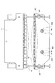
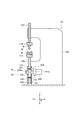
Definitions
- the present disclosure relates to a bending apparatus including a bending correction mechanism that corrects bending that occurs in a mold support member and a mold during bending of a plate-shaped workpiece.
- a press brake as an example of a bending apparatus is a plate-like workpiece set on a die by relatively moving a lower table provided with a die (lower die) and an upper table provided with a punch (upper die). Is bent with a die and a punch.
- an elevating drive mechanism for elevating and lowering a moving table is disposed. At the time of bending, the elevating drive mechanism applies a moving pressure by both the left and right sides of the moving table.
- the press brake may include a bending correction mechanism (also referred to as a crowning mechanism) for correcting such bending deformation.
- Patent Document 1 discloses a bending apparatus equipped with a deflection correction mechanism in which an eccentric portion is provided on a rotating shaft that is rotated by a rotation drive mechanism, and a pressing force that corrects the deflection of the table is generated by the rotation of the eccentric portion. Examples are disclosed.
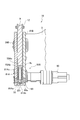
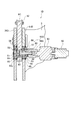
- FIG. 26 is a front view of a press brake provided with a conventional deflection correcting mechanism disclosed in Patent Document 1, and FIG. 27 is a longitudinal sectional view of an essential part thereof.
- the left-right direction X corresponds to the longitudinal direction of the upper table 107 and the lower table 109, which will be described later.
- the horizontal direction is orthogonal to the front-rear direction Y
- the vertical direction is the vertical direction Z.
- the plate-like workpiece W here is arranged so that its longitudinal direction is the left-right direction X, and is bent by the press brake 101.
- the press brake 101 is fixedly provided with a vertical plate-like upper table 107 on the left and right side plates 103, 105, and vertically-movable vertically below the side plates 103, 105. 109.
- elevating drive mechanisms for example, elevating cylinders
- the upper table 107 and the lower table 109 are arranged to face each other in the vertical direction Z.
- a punch P is detachably attached to a position of the upper table 107 facing the lower table 109 via a punch mounting bracket 115.
- a die D is detachably attached to a position of the lower table 109 facing the upper table 107 via a die attachment bracket 117.
- the upper table 107 and the lower table 109 extend linearly along the left-right direction X.
- the punch P and the die D correspond to a pair of molds, and the upper table 107 and the lower table 109 correspond to a pair of mold support members.
- the raising and lowering drive mechanisms 111 and 113 raise the lower table 109 by applying upward moving pressure to the left and right sleeve portions 109a on both sides in the left and right direction X of the lower table 109, whereby the die D and the punch P The workpiece W is bent between.
- the press brake 101 includes a bending correction mechanism 150 for correcting such bending deformation on the lower table 109 side.
- two deflection correction mechanisms 150 for correcting the deflection of the lower table 109 during bending are provided in a portion located in the middle part of the left and right lifting drive mechanisms 111 and 113 of the lower table 109.
- the two deflection correction mechanisms 150 are respectively provided in openings 109c having a rectangular shape when viewed from the front, which are formed symmetrically with respect to the center of the lower table 109 in the left-right direction X.
- Each deflection correction mechanism 150 applies a pressing force (upward pressing force) toward the die D from the side (upper side) opposite to the side (upper end side) of the lower table 109 that supports the die D.
- a pressing force upward pressing force
- amends the bending of the lower table 109 at the time of a bending process is fulfilled.
- the upper block 131 is disposed on the upper surface of each opening 109c, and the lower block 133 is disposed on the lower surface. Between the upper block 131 and the lower block 133, a disc-shaped eccentric rotating plate 135 that is a main element of the deflection correcting mechanism 150 is rotatably arranged.
- the eccentric rotating plate 135 is integrally provided on a rotating shaft 137 whose rotating center axis R is eccentric with respect to the center axis Q thereof.
- a rotation center axis R of the rotation shaft 137 extends in the front-rear direction Y of the press brake 101.
- the outer periphery of the eccentric rotating plate 135 exerts a pressing force on the upper block 131 or the lower block 133 in the opening 109c according to the positional relationship of the center axis Q with respect to the rotation center axis R due to the rotation of the rotation shaft 137.
- the rotary shaft 137 can be rotated through bearings (not shown) in the through holes 139a and 141a of the front plate 139 and the rear plate 141 disposed so as to sandwich the lower table 109 from both the front and rear sides. It is supported by.
- An intermediate portion of the lower table 109 in the left-right direction X can be bent in the up-down direction Z with respect to the front plate 139 and the rear plate 141.
- the lower table 109, the front plate 139, and the rear plate 141 are lifted and lowered together by driving of the lifting drive mechanisms 111 and 113.
- a servo motor 145 as a rotational drive mechanism is connected to the rotary shaft 137 via a speed reducer 143.
- the eccentric rotary plate 135 can be rotated about the rotation center axis R, and an upward pressing force can be applied to the lower table 109 for correcting the deflection.
- the lower table 109 rises and moves closer to the upper table 107.
- the front plate 139 and the rear plate 141 are also raised together with the lower table 109.
- the die D moves toward the punch P, and the punch P enters the V-shaped groove of the die D.
- the lower surface of the workpiece W comes into contact with the left and right shoulders of the V-shaped groove of the die D, and the center portion of the workpiece W is bent into the V-shaped groove of the die D by the tip of the punch P.
- the upper table 107 and the lower table 109 are bent in the vertical direction by the pressure reaction force received from the work W interposed between the tables 107 and 109. That is, the lower surface of the upper table 107 and the punch P is deformed into a concave shape, and the upper surface of the lower table 109 and the die D is deformed into a concave shape.
- the rotation shaft 137 is rotated via the speed reducer 143 by driving and controlling the servo motor 145 in accordance with the operation of the elevating drive mechanisms 111 and 113.
- the eccentric rotating plate 135 is eccentrically rotated about the rotation center axis R by the rotation of the rotating shaft 137, and an upward pressing force is applied from the eccentric rotating plate 135 to the upper block 131 by the upward displacement of the eccentric rotating plate 135.
- the lower table 109 receives an upward pressing force transmitted from the upper block 131, and its upper surface and the upper surface of the die D are deformed into a convex shape. Therefore, the convex deformation of the upper surface of the lower table 109 and the upper surface of the die D cancels the concave deformation of the upper table 107 and the lower surface of the punch P, and the lower table 109 and the upper surface of the die D caused by the pressure reaction force. The As a result, the parallelism of the upper table 107 and the lower surface of the punch P and the lower table 109 and the upper surface of the die D is maintained.
- the press brake 101 described in Patent Document 1 generates all the pressing force necessary for correcting the deflection of the lower table 109 by the driving force of the servo motor 145 that is a rotation driving mechanism. For this reason, the capacity of the servo motor 145 is increased, and the capacity of a bearing or the like that supports the rotating shaft 137 is also increased. As a result, the deflection correction mechanism 150 is increased in size and costs are increased.
- the embodiment aims to reduce the driving force of the rotation drive mechanism in the deflection correction mechanism.
- a pair of mold support members that support a pair of molds for bending a plate-shaped workpiece, and a longitudinal direction of the pair of mold support members is a left-right direction, the left-right direction
- a pair of drive mechanisms that cause the pair of mold support members to move relatively close to each other by bending the workpiece between the pair of molds by applying a moving force in a direction in which the pair of mold support members face each other on both sides. And applying a pressing force toward at least one of the pair of mold support members toward the mold from the side opposite to the side supporting the mold, thereby bending the pair of mold support members during bending.
- a deflection correction mechanism that corrects, and the deflection correction mechanism includes a rotary shaft that is rotatable about a central axis in a direction orthogonal to a direction in which a pressing force for correcting the deflection is applied to the mold support member, Said A rotation drive mechanism for rotating the rotation shaft and an outer peripheral surface centering on a position eccentric with respect to the center axis of the rotation shaft are provided on the rotation shaft, and rotate around the center axis of the rotation shaft.
- An eccentric part that applies a pressing force toward the mold from the outer peripheral surface toward the mold by the eccentric rotation, and a pressing force auxiliary part that assists the pressing force of the eccentric part against the mold support member.
- a bending apparatus is provided.
- the pressing force assisting part assists the pressing force to the mold support member due to the rotation of the eccentric part using the rotational drive mechanism as the power source. For this reason, the required driving force of the rotational drive mechanism can be reduced, the capacity of the rotational drive mechanism can be reduced, and the overall deflection correction mechanism can be reduced in size.
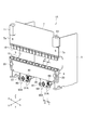
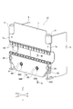
- FIG. 1 is a perspective view of a press brake as a first embodiment of the present invention.
- 2 is a cross-sectional view taken along line AA in FIG.
- FIG. 3 is a perspective view showing the overall configuration of the deflection correction mechanism of FIG.
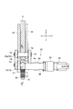
- FIG. 4 is a view taken in the direction of arrow B in FIG. 3 in which members to be attached are added in cross section.
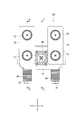
- FIG. 5 is a view taken in the direction of arrow C in FIG. 6 is a cross-sectional view taken along the line DD in FIG. 7 is a cross-sectional view taken along the line EE of FIG.
- FIG. 8 is a cross-sectional view taken along line FF in FIG.
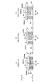
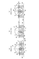
- FIGS. 9A to 9C are operation principle diagrams of the deflection correcting mechanism of FIG.
- FIGS. 10A to 10C are action explanatory views showing a state in which the bracket member rotates and the base member moves in the horizontal direction.
- FIG. 11 is a perspective view of a press brake as a second embodiment of the present invention.
- 12 is a perspective view showing the overall configuration of the deflection correction mechanism of FIG. 13 is a cross-sectional view taken along line HH in FIG. 14 is a cross-sectional view taken along the line II of FIG.
- FIG. 15 is an enlarged cross-sectional view of the deflection correction mechanism of FIG.
- FIGS. 16A to 16C are operation principle diagrams of the deflection correcting mechanism of FIG.
- FIG. 17 is a perspective view of a press brake as a third embodiment of the present invention.
- FIG. 18 is a cross-sectional view taken along the line JJ in FIG. 19 is a cross-sectional view taken along the line KK in FIG.
- FIG. 20 is a perspective view of a press brake as a fourth embodiment of the present invention.
- 21 is a cross-sectional view taken along line LL in FIG. 22 is a cross-sectional view taken along line MM in FIG.
- FIG. 23 is a perspective view of a press brake as a fifth embodiment of the present invention.
- 24 is a cross-sectional view taken along line NN in FIG.
- FIG. 25 is a front view showing a state in which the upper surface of the lower table is elastically deformed so that the upper surface of the lower table is recessed downward before bending by the bending correction mechanism of FIG.
- FIG. 26 is a front view of a press brake provided with a conventional deflection correction mechanism.
- FIG. 27 is a longitudinal sectional view of an essential part of FIG.
- FIG. 1 is a perspective view of the press brake according to the first embodiment
- FIG. 2 is a cross-sectional view taken along the line AA in FIG.
- the horizontal direction is X
- the horizontal direction among the directions orthogonal to the horizontal direction X is the front-rear direction Y
- the vertical direction is vertical among the directions orthogonal to the left-right direction X.
- the left-right direction X corresponds to the longitudinal direction of the upper table 7 and the lower table 9 described later.
- the press brake 1 includes a vertical plate-like upper table 7 that is movable up and down on the left and right side plates 3, 5, and a vertical plate-like lower table 9 that is fixedly provided below the left and right side plates 3, 5. .
- the upper table 7 and the lower table 9 are arranged to face each other in the vertical direction Z.
- a punch as an upper die is detachably attached to a position of the upper table 7 facing the lower table 9 via a punch holder 10 as a punch mounting bracket.
- a die serving as a lower mold is detachably attached to a position of the lower table 9 facing the upper table 7 via a die holder 12 serving as a die mounting bracket.
- the attachment of the punch and die is not shown in FIG. 1, but is the same as that shown in FIGS.
- the upper table 7 and the lower table 9 extend linearly along the left-right direction X.
- the punch and die correspond to a pair of molds
- the upper table 7 and the lower table 9 correspond to a pair of mold support members.
- raising and lowering drive mechanisms for example, raising and lowering cylinders
- the elevating drive mechanisms 11 and 13 are mounted on the left and right side plates 3 and 5, and by applying downward movement pressure to the left and right sleeve portions 7 a on both sides in the left and right direction X of the upper table 7, It lowers, thereby bending the workpiece between the die and punch. That is, the elevating drive mechanisms 11 and 13 move the pair of mold support members relatively close to each other by applying a moving force in the direction in which the pair of mold support members face each other on both sides in the left-right direction.
- a pair of drive mechanisms for bending the workpiece is configured.
- the press brake 1 includes a bending correction mechanism 50 for correcting such bending deformation.
- the deflection correction mechanism 50 is provided on the lower table 9 side opposite to the upper table 7 side on which the elevating drive mechanisms 11 and 13 are provided.
- the bending correction mechanism 50 is located at a position corresponding to the middle portion of the left and right lifting drive mechanisms 11 and 13 with respect to the center of the lower table 9 in the left-right direction X in order to correct the bending of the lower table 9 during bending.
- a front plate 39 is arranged on the front side of the lower table 9 so that the lower table 9 is sandwiched between the front and rear directions Y, and a rear plate is placed on the rear side of the lower table 9.
- 41 is arranged.
- the lower table 9 and the front plate 39 and the rear plate 41 are connected to each other by pins 20 at both ends in the left-right direction X, and the intermediate portion in the left-right direction of the lower table 9 is connected to the front plate 39 and the rear plate 41. Thus, it can be bent in the vertical direction.
- Two deflection correction mechanisms 50 are provided between the front plate 39 and the rear plate 41 and the lower table 9 in the middle between both ends where the lower table 9 and the front plate 39 and the rear plate 41 are pin-coupled to each other.
- the front plate 39 and the rear plate 41 are on the Y-direction side orthogonal to one plane including the left-right direction X and the approaching movement direction (Z-direction) of the pair of mold support members, respectively, of the mold support member having a deflection correction mechanism.
- a holding plate that is attached to the mold support member at both side positions in the direction along the left-right direction X.
- the deflection correction mechanism 50 applies a pressing force (upward pressing force) directed to the die from the side (upper side) opposite to the side (upper end side) supporting the die of the lower table 9 to the lower table 9. It fulfills the function of correcting the deflection of the lower table 9 during bending.
- the deflection correction mechanism 50 will be described in detail below.
- FIG. 3 is a perspective view showing the overall configuration of the deflection correction mechanism 50 of FIG. 1
- FIG. 4 is a view as viewed in the direction of arrow B in FIG. 3 in which a member to be attached is added in cross section
- FIG. 5 is a view in the direction of arrow C in FIG. 6 is a sectional view taken along the line DD in FIG. 4
- FIG. 7 is a sectional view taken along the line EE in FIG. 5
- FIG. 8 is a sectional view taken along the line FF in FIG.
- the deflection correction mechanism 50 in the first embodiment rotates the rotating shaft 60, the pair of base plates 51 and 51 that rotatably support the rotating shaft 60, and the rotating shaft 60.
- an auxiliary spring 80 an auxiliary spring 80.
- the pair of base plates 51, 51 constitutes a base member
- the servo motor 90 constitutes a rotational drive mechanism for rotating the rotary shaft 60
- the pressing assist spring 80 constitutes an elastic member.
- the elastic member constitutes a pressing force assisting member that assists the pressing force against the mold support member.
- the deflection correction mechanism 50 has each configuration shown in FIGS.
- the deflection correction mechanism 50 includes a front plate 39, a rear plate 41, a protruding piece 56, a bracket member 70, an upper connection pin 72, a lower connection pin 73, a spring support bolt 81, and the like.
- the rotation shaft 60 is in a state where the direction of its own rotation center axis R is set to the front-rear direction Y orthogonal to the direction in which the pressing force for correcting the deflection is applied to the lower table 9 (the direction from the bottom to the top).
- the base plate 51 is rotatably supported around the rotation center axis R.
- a circular eccentric part 63 is formed on the rotating shaft 60.
- the circular eccentric portion 63 has a cylindrical outer peripheral surface 63 a centered on an eccentric axis Q that is eccentric by an eccentric amount ⁇ with respect to the rotation center axis R of the rotary shaft 60.
- the circular eccentric part 63 constitutes an eccentric part formed on the rotating shaft 60 so as to have an outer peripheral surface centering on a position eccentric with respect to the central axis of the rotating shaft 60.
- straight body portions 61 and 62 are formed on both axial sides of the circular eccentric portion 63 on the rotation shaft 60.
- the straight body portions 61 and 62 have cylindrical outer peripheral surfaces 61 a and 62 a centering on the rotation center axis R.
- the pair of base plates 51, 51 are arranged in the front-rear direction on the lower ends of the front plate 39 and the rear plate 41 on the front and rear of the lower table 9 via four strip-shaped bracket members 70. Installed at intervals.
- cylindrical outer peripheral surfaces 61 a and 62 a of the straight body portions 61 and 62 on the rotary shaft 60 are provided on the inner periphery of the bearing hole 51 b formed in each base plate 51 via the sleeve 52 and the bearing 53. Is fitted. Thereby, the rotating shaft 60 is rotatably supported with respect to the pair of base plates 51 and 51.
- the output shaft of the servo motor 90 with the speed reducer 92 is connected to the shaft end of the rotating shaft 60 supported by the base plate 51 through a coupling 94. As shown in FIGS. 3 and 4, the servo motor 90 with the speed reducer 92 is fixed to the base plate 51 via a support member 98.
- the four bracket members 70 are paired in the front-rear direction Y and are paired in the left-right direction X. As shown in FIGS. 4 and 7, the upper portions of the left and right bracket members 70 that are paired in the front-rear direction are connected to the front plate 39 and the rear plate 41 by upper connection pins 72. In this case, the upper connecting pin 72 is connected to the front plate 39 and the rear plate 41 through the insertion hole 9a of the lower table 9 so as not to interfere with the lower table 9 when the lower table 9 is bent and deformed.
- the lower part of the left and right bracket members 70 paired in the front-rear direction among the four bracket members 70 is formed by lower connection pins 73 that pass through the respective through holes 51a of the pair of base plates 51, 51. Are connected to each other.
- the lower connecting pin 73 is fitted and fixed in each through hole 51 a of the pair of base plates 51 and 51.
- the upper connecting pin 72 constitutes a holding plate side connecting pin
- the lower connecting pin 73 constitutes a base member side connecting pin.
- the lower connecting pin 73 that connects the lower portions of the pair of front and rear bracket members 70 also serves as a connecting member that connects the pair of front and rear base plates 51 and 51.
- the four connecting pins 72 and 73 are arranged symmetrically with the rotating shaft 60 therebetween, and are located at both left and right ends of the movable member 55.
- the movable member 55 is supported by the base plate 51 via the lower connecting pin 73 so as not to rotate and to be displaceable in the vertical plane.
- the upper connecting pin 72, the lower connecting pin 73, and the bracket member 70 can be rotated relative to the fitting portion between the through hole 70 a of the bracket member 70 and the upper connecting pin 72 and the lower connecting pin 73.
- a sleeve 71 is disposed. That is, the bracket member 70 is rotatably supported by the holding plate and the base member, with the support shaft in a direction orthogonal to the left and right direction X and one plane including the moving directions of the pair of mold support members.
- the movable member 55 is disposed between the pair of base plates 51 and 51.
- the circular eccentric part 63 on the rotary shaft 60 rotatably supported by the pair of base plates 51, 51 has a cylindrical outer peripheral surface 63 a on the inner periphery of a circular opening 58 formed in the movable member 55. Is positioned between the pair of base plates 51 and 51 by being fitted so as to be relatively rotatable.
- the direction in which the pressing force is applied to the lower table 9 (upward direction) for correcting the deflection is defined as the positive direction
- the opposite direction (downward direction) is defined as the negative direction. Since the circular eccentric part 63 and the movable member 55 are combined as described above, the movable member 55 receives a pressing force according to the rotational position of the circular eccentric part 63. That is, the circular eccentric portion 63 rotates eccentrically around the rotation center axis R, so that the movable member 55 can move the cylindrical outer periphery of the circular eccentric portion 63 according to the position of the eccentric axis Q of the circular eccentric portion 63 with respect to the rotation center axis R. From the surface 63a, a positive pressure or a negative pressure is received.
- the movable member 55 is a member that transmits at least a positive pressing force to the lower table 9.
- the movable member 55 is provided separately from the lower table 9.
- a pressing surface 55 a is provided on the upper end surface of the movable member 55
- a pressed surface 9 c is provided on the lower end surface of the lower table 9.
- the pressed surface 9c of the lower table 9 receives a pressing force in the plus direction from the movable member 55 when the pressing surface 55a of the movable member 55 comes into contact therewith.
- projecting pieces 56 having vertical through holes 56 a are provided at the left and right ends of the movable member 55. These left and right projecting pieces 56 are located below the bolt connecting portion 74 provided at the middle portion in the longitudinal direction of the lower connecting pin 73 (position where the movable member 55 is located).
- the bolt connecting portion 74 of the lower connecting pin 73 is provided with a vertical through hole 74a having a screw hole, and a spring support bolt 81 as an elastic member support rod with the head 81a down in the through hole 74a.
- the tip (upper end) 81b is screwed. As shown in FIGS. 6 and 7, the tip 81 b of the spring support bolt 81 is coupled to the bolt connecting portion 74 with a nut 83.
- the spring support bolt 81 passes through the through hole 56a of the protruding piece 56 of the movable member 55 so as to be relatively movable in the axial direction and the diametrical direction below the lower connecting pin 73.
- a pressing assist spring 80 is interposed in a compressed state.
- the pressing assist spring 80 applies an upward biasing force to the movable member 55 via the protruding piece 56.
- the inner diameter of the through hole 56 a is formed sufficiently larger than the diameter of the portion inserted into the through hole 56 a of the spring support bolt 81.
- the pressing auxiliary spring 80 gives a positive biasing force corresponding to the amount of deformation of the movable member 55 to the movable member 55.
- the pressing auxiliary spring 80 has a lower end that is a fixed end supported by the base plate 51 via a spring support bolt 81 and a lower connecting pin 73, and an upper end that is a free end is movable so as to apply a biasing force to the movable member 55.
- the protrusion 55 of the member 55 is engaged.
- the movable member 55 may be integrated with the lower table 9 which is a mold support member as will be described later. Accordingly, the elastic member support rod having one end connected to the center in the axial direction of the base member side connection pin penetrates the mold support member on the side opposite to the holding plate side connection pin with respect to the base member side connection pin, and the elastic member support rod penetrates. An elastic member is disposed between the mold support member of the part and the other end of the elastic member support rod.
- the pressing assist spring 80 is composed of a stack of a large number of disc springs that generate a repulsive force in a compressed state.
- the disc spring laminated body is inserted into the outer periphery of the spring support bolt 81.
- the press brake 1 lowers the upper table 7 by the elevating drive mechanisms 11 and 13 to bend the workpiece. At that time, the upper table 7 and the punch and the lower table 9 and the die may be bent and deformed depending on the magnitude of the reaction force. In order to correct the bending, the bending correction mechanism 50 is operated in accordance with the progress of the bending process.
- the circular eccentric portion 63 provided on the rotating shaft 60 is circular with the movable member 55. It rotates eccentrically in the opening 58.
- the movable member 55 that is non-rotatably supported by the base plate 51 is displaced in the vertical direction as indicated by an arrow T according to the rotational position of the circular eccentric part 63.
- the pressing force generated by the rotation of the circular eccentric part 63 can be suppressed by the amount of the urging force of the pressing assist spring 80, and the rotational driving force by the servo motor 90 of the rotating shaft 60 can be reduced.
- the capacity of the servo motor 90 and the speed reducer 92 can be reduced, and the capacity of the bearing 53 for supporting the rotating shaft 60 can be reduced.
- the movable member 55 can be displaced up and down by 2 ⁇ at the maximum by the rotation of the circular eccentric part 63. Therefore, when the lowest position of the movable member 55 is used as a reference, the movable member 55 can be displaced 2 ⁇ above the reference position.
- the upward pressing force at this time is the sum of the upward pressing force generated by the rotation of the circular eccentric part 63 and the urging force corresponding to the deformation amount of the pressing auxiliary spring 80 at that time.
- the force necessary to displace the movable member 55 to the lowest position (reference position) compresses and deforms the pressing auxiliary spring 80 to the maximum. This is a force required to cause the pressing assist spring 80 to antagonize an urging force (restoring force) generated when the pressing assist spring 80 is compressed and deformed to the maximum.
- the movable member 55 when the movable member 55 is at the lowest position (reference position), the movable member 55 does not exert an upward pressing force on the lower table 9.
- the force generated by the circular eccentric portion 63 may correspond to the maximum deformation amount of the pressing assist spring 80 due to the rotation of the circular eccentric portion 63.
- the eccentric amount of the circular eccentric portion 63 is ⁇
- the amount of deformation (compression amount) of the pressing auxiliary spring 80 is increased by ⁇ at the maximum from the neutral position in FIG. Increases the power of. Therefore, it is necessary to finally generate a pressing force that can counter the urging force of the increasing pressing auxiliary spring 80 in the circular eccentric portion 63.
- the position of the movable member 55 in the state shown in FIG. 9A is the reference position
- the movable member 55 is displaced from the reference position to the neutral position in the vertical direction as shown in FIG. 9B
- the eccentric axis Q of the circular eccentric part 63 is aligned on the same horizontal line as the rotation center axis R.
- the biasing force of the pressing assist spring 80 is the deformation amount of the pressing assist spring 80 by ⁇ . It decreases to the magnitude of the spring force when it decreases.
- the driving force of the servo motor 90 it is necessary to set the driving force of the servo motor 90 to 300 kN at the maximum, and therefore it is assumed that the servo motor 90 capable of exerting a force of 300 kN is used.
- the external output at this time can be 500 kN, which is a resultant force of the upward force 300 kN due to the rotation of the circular eccentric part 63 and the biasing force (100 kN + 100 kN) according to the deformation amount at that time by the pressing auxiliary spring 80.
- the auxiliary pressing spring 80 As described above, in the absence of the pressing assist spring 80, it is necessary to set the driving force of the servo motor 90 to 500 kN in order to generate a pressing force of 500 kN for correcting the deflection.
- the auxiliary pressing spring 80 is provided as in the first embodiment, the urging force (100 kN + 100 kN) of the auxiliary pressing spring 80 can be used as the auxiliary force, and accordingly, the required driving force of the servo motor 90 is correspondingly increased. It can be kept small.
- the driving force of the servo motor 90 can be suppressed to 300 kN by providing the pressing assist spring 80.
- the bending of the lower table 9 can be freely controlled, so that stable bending over time can be performed.
- the biasing force of the pressing auxiliary spring 80 is applied to the lower table 9 through the movable member 55 as a positive pressing force. Can do.
- the pressing force to be generated by rotating the circular eccentric portion 63 on the rotating shaft 60 can be reduced by the amount of the applied pressing force, and the necessity of the servo motor 90 with the speed reducer 92 as the rotation drive mechanism is necessary. Driving force can be reduced.
- the capacity of the servo motor 90 with the speed reducer 92 can be reduced, and the capacity of the bearing 53 that supports the rotating shaft 60 can be reduced, so that the size and cost can be reduced.
- the pressing assisting spring 80 which is an elastic member, is used as the pressing force assisting portion. Therefore, the size and cost can be reduced with a simple and inexpensive configuration.
- the deflection correction of the lower table 9 can be accurately performed with a good balance.
- the table side on which the lift drive mechanisms 11 and 13 are provided and the table side on which the deflection correction mechanism 50 is provided are separated, that is, the lift drive mechanisms 11 and 13 are provided on the upper table 7 side.
- the bending correction mechanism 50 is provided on the lower table 9 side to correct the bending of the lower table 9 during processing. Therefore, the complexity of the layout of the mechanism due to the lifting drive mechanisms 11 and 13 and the deflection correcting mechanism 50 being on the same table side can be avoided.
- the raising and lowering drive mechanisms 11 and 13 are provided on the upper table 7 side, and the bending correction mechanism 50 is provided on the lower table 9 side, thereby correcting the bending of the lower table 9 during processing. For this reason, it is only necessary to apply a pressing force to correct the deflection from below to above, and the deflection correction mechanism 50 can be arranged below the lower table 9 so as not to get in the way.
- the movable member 55 is provided separately from the lower table 9, and the movable member 55 and the lower table are brought into contact with each other by the contact between the pressing surface 55 a of the movable member 55 and the pressed surface 9 c of the lower table 9. 9 is transmitted with a pressing force for correcting the deflection. For this reason, by providing the pressed surface 9c with which the movable member 55 contacts at the lower end surface of the lower table 9, it is necessary to provide the lower table 9 with an opening that causes a reduction in rigidity as in the conventional example shown in FIG. Absent. That is, the rigidity of the lower table 9 can be improved, and bending deformation during bending can be reduced.
- a pressing force is applied to the movable member 55 disposed between the pair of base plates 51, 51 from the circular eccentric portion 63, and the pressing force is applied to the pressing surface 55 a on the upper end surface of the movable member 55 and the lower table.
- 9 is transmitted to the lower table 9 through the contact of the pressed surface 9c at the lower end surface of 9. For this reason, it is possible to apply a pressing force necessary for correcting the deflection to the lower table 9 with a good balance in the front-rear direction.
- the press brake 1 is configured such that the front plate 39 and the rear plate 41 coupled to the lower table 9 by the pins 20 on both sides in the left-right direction and the base plate 51 are connected via the bracket member 70. Therefore, when the movable member 55 is pressed upward and the lower table 9 is deflected and corrected, the reaction force of the upward pressing force of the circular eccentric portion 63 against the movable member 55 is applied to the base plate 51 and the bracket member 70. Through the front plate 39 and the rear plate 41.
- the left and right ends of the pair of base plates 51 are connected to the front plate 39 and the rear plate 41 via four bracket members 70.
- the movable member 55 is supported so as not to be rotatable and displaceable in a vertical plane via lower connecting pins 73 symmetrically arranged at both left and right ends in order to interconnect the pair of base plates 51, 51. For this reason, the movable member 55 can be supported with good balance.
- the pressing auxiliary spring 80 is interposed between the movable member 55 and the lower connecting pin 73 that also serves as a connecting member, the urging force of the pressing auxiliary spring 80 can be smoothly transmitted to the movable member 55 with a simple configuration. Can do.
- Projecting pieces 56 having through holes 56a in the vertical direction are provided on the left and right ends of the movable member 55.
- the upper ends of the spring support bolts 81 are coupled to the lower connection pins 73 disposed at the left and right ends of the base plate 51.
- a spring support bolt 81 is inserted into the through hole 56a of the projecting piece 56 disposed so as to be positioned below the bolt connecting portion 74 of the lower connecting pin 73.
- a pressing auxiliary spring 80 is interposed in a compressed state between the head 81 a at the lower end of the spring support bolt 81 and the protruding piece 56, and the pressing auxiliary spring 80 applies an upward biasing force to the movable member 55 via the protruding piece 56. Has been granted. Therefore, the urging force of the pressing assist spring 80 can be applied to the movable member 55 in a well-balanced manner.
- the four bracket members 70 are connected to the front plate 39 and the rear plate 41 and the pair of base plates 51 and 51 by pins (upper connection pins 72 and lower connection pins 73), respectively. For this reason, by attaching the pin to the bracket member 70 so as to be rotatable, it is possible to prevent excessive stress from being generated in each member. Further, since the lower connecting pin 73 also serves as a connecting member that connects the pair of base plates 51, 51, the configuration can be simplified and the number of parts can be reduced.
- At least a pair of bracket members 70 are provided on both sides in the axial direction of the rotation shaft 60 of the lower table 9.
- the pins 73 are connected to each other.
- the spring support bolt 81 having one end connected to the center in the axial direction of the lower connection pin 73 passes through the movable member 55 on the side opposite to the upper connection pin 72 with respect to the lower connection pin 73, and the movable portion in which the spring support bolt 81 passes is movable.
- a pressing auxiliary spring 80 is disposed between the member 55 and the other end of the spring support bolt 81.
- the pressing auxiliary spring 80 can apply a biasing force to the movable member 55 at the center in the axial direction of the lower connecting pin 73.
- the movable member 55 can push up the lower table 9 in a stable posture, and the deflection correction can be performed efficiently.
- the pressing assist spring 80 is composed of a laminated body of a plurality of disc springs that generate a repulsive force in a compressed state, a strong biasing force can be generated with a small amount of deformation.
- the movable member 55 pushes up the lower table 9 with a large force of 500 kN at maximum as an external output. For this reason, when the movable member 55 receives a lateral pressing force, a large frictional force is generated between the pressing surface 55a of the movable member 55 and the pressed surface 9c of the lower table 9, and the servo motor 90 is large. It adversely affects each part such as receiving a load.
- the bracket member 70 shown in FIGS. 4, 7, and the like is rotatably connected to the front plate 39 and the rear plate 41 via the upper connection pins 72, and the lower portion is connected to the base plate 51. It is rotatably connected via a connecting pin 73. That is, the bracket member 70 is rotatably supported by the holding plate and the base member, with the support shaft in a direction orthogonal to the left and right direction X and one plane including the moving directions of the pair of mold support members.
- the frictional force between the pressing surface 55a and the pressed surface 9c when the movable member 55 receives a lateral pressing force is a friction generated when the bracket member 70 rotates via the upper connecting pin 72 and the lower connecting pin 73.
- the frictional force between the pressing surface 55a and the pressed surface 9c opposes the lateral pressing force received by the movable member 55, and the movement of the movable member 55 in the horizontal direction is suppressed.
- bracket member 70 swings and rotates in the clockwise direction in FIG. 10 about the upper connecting pin 72 so that the lower part moves to the left side.
- bracket member 70 serves as a link member between the front plate 39 and the rear plate 41 and the base plate 51.
- FIGS. 10 (a) to 10 (c) show the movement of the movable member 55 and the bracket member 70 corresponding to FIGS. 9 (a) to 9 (c).
- the movable member 55 As the base plate 51 moves, as shown in FIGS. 10 (b) to 10 (c), the movable member 55 is shown as a two-dot chain line upward in a state in which the movement in the horizontal direction is suppressed. Moving. When the base plate 51 moves in the horizontal direction, the servo motor 90 attached to the base plate 51 via the support member 98 also moves together.
- the bracket member 70 rotates and the base plate 51 moves to absorb the lateral pressing force. For this reason, it can suppress that a big load acts on the servomotor 90, and can suppress having a bad influence on each member.
- FIG. 11 is a perspective view corresponding to FIG. 1 of the press brake 1A according to the second embodiment
- FIG. 12 is a perspective view corresponding to FIG. 3 of the deflection correcting mechanism 50A in the press brake 1A
- 13 is a cross-sectional view taken along line HH in FIG. 11
- FIG. 14 is a cross-sectional view taken along line II in FIG.
- the bracket member 70 in the first embodiment is omitted as a structure for suppressing the horizontal movement of the movable member 55 as shown in FIG.
- an eccentric ring 91 as an eccentric annular member is rotatably provided between the rotating shaft 60 and the pair of base plates 51A.
- the base plate 51 ⁇ / b> A includes mounting portions 51 ⁇ / b> Aa that protrude in the left-right direction at both left and right upper ends.
- the base plate 51 ⁇ / b> A is fixed to the front plate 39 and the rear plate 41 by fastening the mounting portion 51 ⁇ / b> Aa to the lower ends of the front plate 39 and the rear plate 41 with a pair of left and right bolts 93. Accordingly, the deflection correction mechanism 50A is attached to the lower table 9 via the base plate 51A, the front plate 39, and the rear plate 41.
- FIG. 15 is an enlarged cross-sectional view of the deflection correction mechanism 50A in FIG. 13, and corresponds to FIG. 8 of the first embodiment.
- the eccentric ring 91 of the deflection correction mechanism 50A is rotatably provided between a bearing 53 provided on the straight body portion 61 of the rotating shaft 60 and a cylindrical bush 95 provided on the inner peripheral side of the base plate 51A. It has been.
- the eccentric ring 91 has a circular outer peripheral surface in the same manner as the circular eccentric portion 63 equivalent to the first embodiment.
- 16A to 16B correspond to FIGS. 9A to 9B.
- the eccentric axis U of the eccentric ring 91 is vertically above the rotational center axis R in a state where the eccentric axis Q of the circular eccentric portion 63 is positioned vertically below the rotational center axis R.
- the eccentric axis Q of the circular eccentric portion 63 is eccentric by an eccentric amount ⁇ with respect to the rotation center axis R of the rotation shaft 60, whereas the eccentric axis U of the eccentric ring 91 is aligned with the rotation center axis R of the rotation shaft 60.
- it is eccentric by an eccentric amount ⁇ .
- the eccentric amount ⁇ of the eccentric ring 91 is larger than the eccentricity ⁇ of the circular eccentric part 63 ( ⁇ > ⁇ ), but may not be large ( ⁇ ⁇ ⁇ ).
- the eccentric ring 91 has the front plate 39, the rear plate so as to have an outer peripheral surface centered at a position different from the eccentric axis Q of the circular eccentric portion 63 with respect to the rotation center axis R of the rotary shaft 60.
- a base plate 51 ⁇ / b> A attached to the plate 41 and a rotary shaft 60 are rotatably provided.
- the eccentric axis U of the eccentric ring 91 is positioned vertically above the rotation center axis R in a state where the eccentric axis Q of the circular eccentric portion 63 is positioned vertically below the rotation center axis R. positioned.
- the eccentric axis U of the eccentric ring 91 may be a position where the eccentric ring 91 is slightly rotated left and right with respect to the position of FIG.
- the support member 98 ⁇ / b> A that supports the servo motor 90 with the speed reducer 92 includes a fixture 96 at the tip.
- the servo motor 90 with the speed reducer 92 is fixed to the eccentric ring 91 by fastening the fixture 96 to the side surface of the eccentric ring 91 with a bolt 97.
- the eccentric ring 91 rotates, the entire servo motor 90 rotates integrally.
- the pair of base plates 51 ⁇ / b> A has protrusions 51 ⁇ / b> Ab that protrude in the left-right direction on the left and right sides of the lower part.
- the projecting portions 51 ⁇ / b> Ab of the pair of base plates 51 ⁇ / b> A facing each other are connected to each other by a connector 99.
- the part corresponding to the base plate 51 ⁇ / b> A has a circular shaft shape and is fitted to the base plate 51 ⁇ / b> A, and the end portion in the axial direction is fixed to the base plate 51 ⁇ / b> A by the mounting plate 100.
- the screw portion 81Ab at the tip protrudes further downward from the connector 99 than the small diameter portion 81Aa, and the nut 201 is fastened to the protruded screw portion 81Ab.
- the nut 201 is fixed to the spring support bolt 81A by fastening.
- the nut 201 is, for example, a double nut so as not to be loosened by being fixed to the spring support bolt 81A.
- the movable member 55A has spring support portions 55Ab projecting in the left-right direction at the left and right ends of the upper portion. Are in contact.
- a pressing assist spring 80 as an elastic member is provided between the head 81Ac of the spring support bolt 81A and the connector 99.
- the auxiliary pressing spring 80 presses the head 81Ac of the spring support bolt 81A upward.
- the movable member 55A is positioned below to compress the pressing assist spring 80.
- the nut 201 is located at a lower position away from the connector 99, and a gap is formed between the nut 201 and the connector 99. Accordingly, when the circular eccentric part 63 rotates from the state of FIG. 16A and shifts to the state of FIGS. 16B and 16C, the nut 201 is connected to the connector along with the extension of the pressing assist spring 80. 99, the spring support bolt 81 ⁇ / b> A moves upward with respect to the connector 99.
- the pressing assisting spring 80 applies a pressing force directed toward the upper plus direction to the movable member 55A, as in the first embodiment.
- a pressing surface 55Aa that presses the pressed surface 9c of the lower table 9 is formed on the upper surface of the movable member 55A.
- the bending correction mechanism 50A When bending a workpiece by the press brake 1A, the bending correction mechanism 50A is operated for bending correction, as in the first embodiment.
- the servo motor 90 of the deflection correction mechanism 50A is driven to rotate the rotating shaft 60 in the direction of arrow V in FIG. 16A, the circular eccentric portion 63 provided on the rotating shaft 60 is moved to the movable member 55A. It rotates eccentrically in the circular opening 58.
- the movable member 55A supported non-rotatably by the base plate 51A is displaced in the vertical direction according to the rotational position of the circular eccentric part 63 to perform the deflection correction.
- the pressing assisting spring 80 presses the movable member 55A upward via the head 81Ac of the spring support bolt 81A, so that the driving force of the servo motor 90 is reduced.
- the movable member 55A is pressed upward by the circular eccentric portion 63 and moved upward by a displacement amount h1. Further, the movable member 55A receives a lateral pressing force by the circular eccentric portion 63 in the horizontal direction on the right side in FIG. However, a large frictional force is generated between the pressing surface 55Aa of the movable member 55A and the pressed surface 9c of the lower table 9 due to a reaction force during bending. Let this frictional force be f1.
- the eccentric ring 91 is freely rotatable between the bearing 53 on the rotating shaft 60 side and the bush 95 on the base plate 51A side.
- the sum of the frictional forces during rotation of the eccentric ring 91 against the bearing 53 and the bush 95 is defined as f2.
- the frictional force f2 on the eccentric ring 91 side is sufficiently smaller than the frictional force f1 on the movable member 55A side (f1> f2). For this reason, the frictional force between the pressing surface 55Aa and the pressed surface 9c opposes the lateral pressing force received by the movable member 55 and the horizontal movement of the movable member 55A is suppressed.
- Servo motor 90 is attached to the side surface of eccentric ring 91 with rotation shaft 60 as the center, and moves to the left in FIG.
- the movable member 55A moves upward by the displacement amount h2
- the movable member 55A presses the lower table 9 upward to correct the deflection.
- the maximum deflection correction force is exerted on the lower table 9.
- the pressing assist spring 80 applies an elastic force so as to press the movable member 55A upward, and the elastic force assists the driving force of the servo motor 90. Become.
- the pressing force that should be generated by rotating the circular eccentric portion 63 on the rotating shaft 60 can be reduced by the amount of the elastic force to assist, and the necessary driving force of the servo motor 90 can be reduced.
- the eccentric axis Q of the circular eccentric portion 63 is positioned vertically above the rotation center axis R. To do. During this transition, the rotation shaft 60 (rotation center axis R) moves to the right in the horizontal direction in FIG. 16, and returns to the same position as in FIG. 16A in the horizontal direction.
- the movement of the movable member 55A to the right in the horizontal direction is suppressed when the circular eccentric part 63 rotates 90 degrees from the state of FIG. 16A and shifts to the state of FIG. 16B. Then, the rotating shaft 60 (servo motor 90) moves to the left in the horizontal direction by the rotation of the eccentric ring 91.
- the force that the movable member 55A tries to move to the right in the horizontal direction is absorbed by the rotation shaft 60 (servo motor 90) moving to the left in the horizontal direction. Thereby, it can suppress that a big load is applied to the servomotor 90 which rotates the rotating shaft 60.
- the bracket member 70 serving as a link member in the first embodiment is omitted, and an eccentric ring 91 is provided instead. For this reason, compared with 1st Embodiment, a structure can be simplified as a whole.
- FIG. 17 is a perspective view corresponding to FIG. 11 of the press brake 1B according to the third embodiment
- FIG. 18 is a JJ sectional view of FIG. 17
- FIG. 19 is a KK sectional view of FIG.
- the base plate 51A in the second embodiment of FIG. 11 is eliminated, and the straight body 61 provided with the eccentric ring 91 of the rotating shaft 60 is directly attached to the front plate 39B and the rear plate 41B. Yes.
- the front plate 39B and the rear plate 41B are formed to be larger than the front plate 39 and the rear plate 41 of FIG. 11 so that the portion corresponding to the base plate 51A protrudes downward.
- the movable member 55A is basically the same as that of the second embodiment, the head 81Ac of the spring support bolt 81A is in contact with the lower surface of the spring support 55Ab, and the pressing auxiliary spring 80 is the head of the spring support bolt 81A. 81Ac is pressed upward.
- the connecting tool 99 into which the small diameter portion 81Aa of the spring support bolt 81A is inserted is fixed to the front plate 39B and the rear plate 41B at both ends in the axial direction.
- the rotating shaft 60 is attached to the base plate 51 ⁇ / b> A fixed to the lower part of the front plate 39 and the rear plate 41.
- the rotary shaft 60 is directly attached to the front plate 39B and the rear plate 41B. The movement of each part by driving the servo motor 90 of the deflection correction mechanism 50B in the third embodiment is the same as that in the second embodiment.
- the rotation shaft 60 is rotated by the drive of the servo motor 90, and the circular eccentric portion 63 is rotated along with this, and the movable member 55A is pushed up to correct the deflection.
- the pressing assist spring 80 presses the movable member 55A upward, so that the driving force of the servo motor 90 is reduced.
- the eccentric ring 91 rotates in the direction opposite to the circular eccentric portion 63.
- the rotation center axis R of the rotation shaft 60 moves to the left in the horizontal direction, and the movement of the movable member 55A to the right in the horizontal direction is suppressed.
- a large load can be prevented from being applied to the servo motor 90 that rotates the rotating shaft 60, and the pair of base plates 51A can be eliminated from the second embodiment.
- the number of points can be reduced, and the structure can be simplified.
- a base plate 51A as a rotating shaft support member that rotatably supports the rotating shaft 60 is attached to the front plate 39 and the rear plate 41 as holding plates.
- the front plate 39 and the rear plate 41 can be used substantially the same as those in the embodiment of FIG. 1, and the enlargement of the front plate 39 and the rear plate 41 can be suppressed as compared with the third embodiment.
- FIG. 20 is a perspective view corresponding to FIG. 11 of the press brake 1C according to the fourth embodiment
- FIG. 21 is an LL sectional view of FIG. 20
- FIG. 22 is an MM sectional view of FIG.
- the movable member 55A in the third embodiment shown in FIG. 17 is eliminated, and the portion provided with the circular eccentric portion 63 of the rotating shaft 60 is directly attached to the lower table 9C.
- the front plate 39C and the rear plate 41C are configured to project the portion corresponding to the base plate 51A downward with respect to the front plate 39 and the rear plate 41 of FIG. Largely formed.
- the rotating shaft 60 is attached to substantially the center in the vertical direction of the front plate 39C and the rear plate 41C.
- the head 81Ac of the spring support bolt 81A is in contact with the lower surface of the lower table 9C and is pressed toward the lower table 9C by the pressing auxiliary spring 80.
- both ends in the axial direction of the connecting member 99 into which the small diameter portion 81Aa of the spring support bolt 81A is inserted are fixed to the front plate 39C and the rear plate 41C, respectively.
- the rotation shaft 60 is rotated by the drive of the servo motor 90 of the deflection correction mechanism 50C, and the circular eccentric portion 63 is rotated accordingly, whereby the lower table 9 is directly pushed upward. .
- the bending correction at the time of bending is performed on the lower table 9C.
- the pressing assist spring 80 presses the lower table 9 upward via the head 81Ac of the spring support bolt 81A, so that the driving force of the servo motor 90 is reduced.
- the eccentric ring 91 rotates in the opposite direction to the circular eccentric part 63 in the same manner as in the third embodiment.
- the rotation center axis R of the rotation shaft 60 moves to the left in the horizontal direction as shown in FIG.
- the circular eccentric portion 63 applies a lateral pressing force that presses the lower table 9C to the right in the horizontal direction.
- the fourth embodiment it is possible to suppress a large load from being applied to the servo motor 90 that rotates the rotating shaft 60, and in addition to the second embodiment of FIG. 11, the pair of base plates 51A and the movable member 55A. Therefore, the number of parts can be reduced and the structure can be simplified.
- the circular eccentric portion 63 applies a pressing force directed toward the mold to the movable member 55A separate from the mold support member, and the movable member 55A.
- a pressing surface 9c that receives a pressing force from the movable member 55A when the pressing surface 55Aa contacts is provided on the mold support member.
- the lower table 9 which is a mold supporting member can be used substantially the same as the embodiment of FIG. 1, and compared with the fourth embodiment of FIG. 20, the lower table 9 is provided with the movable member 55A. Increase in size can be suppressed.
- FIG. 23 is a perspective view corresponding to FIG. 11 of the press brake 1D according to the fifth embodiment
- FIG. 24 is an NN cross-sectional view of FIG.
- the pressing assist spring 80 is eliminated from the fourth embodiment shown in FIG. Accordingly, the spring support bolt 81A and the connecting tool 99 used in the fourth embodiment are also omitted.
- the pressing assist spring 80 applies an upward biasing force to the lower table 9C.
- the lower table 9C instead of providing the pressing assist spring 80, the lower table 9C itself is elastically deformed in advance downward in the direction opposite to the direction in which the deflection is corrected.
- the portion of the rotating shaft 60 that includes the circular eccentric portion 63 is located on the lower table 9C, and the straight body portions 61 and 62 that include the eccentric ring 91 of the rotating shaft 60 are the front plate 39D. And it is the same as that of 4th Embodiment, such as being located in backplate 41D.
- the servo motor 90 including the rotation shaft 60 is replaced with the front plate 39D and the rear plate 41D. Is assembled to the lower table 9C including At this time, the eccentric ring 91 is in a position rotated in the direction of the arrow W from the state of FIG. 16A, as in FIG.
- the servo motor 90 is driven to rotate the rotating shaft 60 in the direction opposite to the arrow V to obtain the reference position shown in FIG. 16 (a).
- the eccentric axis Q of the circular eccentric part 63 is located at the lower part of the rotation center axis R in the vertical direction
- the eccentric axis U of the eccentric ring 91 is located at the upper part of the rotation center axis R in the vertical direction. That is, the three axes of the rotation center axis R, the eccentric axis Q, and the eccentric axis U are located on the same straight line in the vertical direction.
- the circular eccentric part 63 is pressed downward against the lower table 9C.
- the upper surface of the lower table 9C is elastically deformed so that the center in the left-right direction is recessed downward, as indicated by a two-dot chain line in FIG.
- the upper surfaces of the front plate 39D and the rear plate 41D are elastically deformed so as to protrude upward as indicated by broken lines.
- the elastic deformation of the front plate 39D and the rear plate 41D in the opposite direction to the lower table 9C is caused by the reaction force of the force pressing downward on the lower table 9 by the rotating shaft 60 via the rotating shaft 60. Due to acting upwards.
- the lower table 9C is elastically deformed so that the upper surface is recessed downward, and has an elastic force to return the upper surface to a flat shape. However, the lower table 9C is lowered by the circular eccentric portion 63 in the state of FIG. The state of being recessed is maintained. For this reason, the external output by the servo motor 90 in FIG. 16A becomes zero (0 kN), and no upward pressing force is applied to the lower table 9C.
- the upper surface of the lower table 9C including the die holder 12 is recessed downward, so that the lower surface of the center in the left-right direction of the upper table 7 is indicated by a two-dot chain line in FIG. It is necessary to project downward.
- the workpiece can be accurately bent.
- a plurality of punch holders 10 provided in the left-right direction shown in FIG. 25 are protruded and moved downward. Specifically, with respect to the plurality of punch holders 10, the protrusion amount at the central portion in the left-right direction is maximized, and the protrusion amount is gradually decreased from the center portion along both sides in the left-right direction.
- the state in which the upper surface of the lower table 9C is elastically deformed so as to be concave downward corresponds to the state in which the pressing assist spring 80 in the first to fourth embodiments is maximally compressed. From this state, the rotary table 60 is rotated in the direction of the arrow V in FIG. 16A by driving the servo motor 90 as in the example of FIG. Pressed.
- the lower table 9C is pressed upward, so that at the initial stage of processing, the upper surface of the lower table 9C and the lower surface of the upper table 7 are substantially flat, and deflection correction is performed.
- the eccentric ring 91 rotates in the opposite direction to the circular eccentric part 63 as the circular eccentric part 63 rotates.
- the rotation center axis R of the rotation shaft 60 moves to the left in the horizontal direction as shown in FIG.
- the circular eccentric portion 63 applies a lateral pressing force that presses the lower table 9C to the right in the horizontal direction.
- the fifth embodiment it is possible to prevent a large load from being applied to the servo motor 90 that rotates the rotary shaft 60, and it is possible to eliminate the pair of base plates 51A and the movable member 55A compared to the second embodiment. Therefore, the number of parts can be reduced correspondingly, and the structure can be simplified.
- the pressing force assisting member is a lower table 9C that is a die support member that is elastically deformed in a direction opposite to the direction of bending during bending. Therefore, the pressing assist spring 80 in the first to fourth embodiments is not necessary, and the number of parts can be reduced correspondingly, thereby simplifying the configuration.
- the deflection correction mechanisms 50 to 50D are provided on the lower table 9, 9C side and the elevating drive mechanisms 11, 13 are provided on the upper table 7 side is shown.
- the deflection correction mechanisms 50 to 50D may be provided on the upper table 7 side
- the elevating drive mechanisms 11 and 13 may be provided on the lower tables 9 and 9C side.
- the elevating drive mechanisms 11 and 13 and the deflection correction mechanisms 50 to 50D may be provided on the same table side (upper table side or lower table side).
- the direction in which the axis direction of the rotating shaft 60 is directed may be other than the front-rear direction as long as it is a direction orthogonal to the direction of the pressing force for correcting the deflection.
- the pressing assist spring 80 is configured by a disc spring laminated body has been described, but other strong springs may be used.
- the press brake 1 in which the upper table 7 and the lower tables 9 and 9C, which are mold support members, are opposed to each other in the vertical direction is shown as an example of the bending apparatus, but the directionality of the mold support member is not limited.
- the present invention can also be applied to a bending apparatus of this type.
- the present invention when a pair of mold support members that respectively support a pair of molds are moved closer to each other, bending that occurs in the mold support member or the mold when a plate-shaped workpiece is bent between the pair of molds is performed. It can be used for a bending apparatus capable of correcting.
Landscapes
- Engineering & Computer Science (AREA)
- Mechanical Engineering (AREA)
- Bending Of Plates, Rods, And Pipes (AREA)
Abstract
撓み補正機構(50)は、一対の型支持部材(7,9)の少なくともいずれか一方(9)に型(D)に向けた押圧力を加えて、一対の型支持部材(7,9)の撓みを補正する。撓み補正機構(50)は、回転軸(60)と、回転駆動機構(90)と、偏心部(63)と、押圧力補助部(80)とを備える。回転軸(60)は、型支持部材(9)に対して撓み補正のための押圧力を加える方向と直交する方向の中心軸線回りに回転自在である。回転駆動機構(90)は、回転軸(60)を回転させる。偏心部(63)は、回転軸(60)の中心軸線に対して偏心した位置を中心とする外周面を有するように回転軸(60)上に設けられ、回転軸(60)の中心軸線回りの回転に伴う偏心回転によって、外周面から型支持部材(9)に対し型(D)に向かう押圧力を与える。押圧力補助部(80)は、偏心部(63)の型支持部材(9)に対する押圧力を補助する。
Description
本開示は、板状のワークの曲げ加工時に型支持部材や型に生じる撓みを補正する撓み補正機構を備えた曲げ加工装置に関する。
曲げ加工装置の一例としてのプレスブレーキは、ダイ(下型)を備える下部テーブルとパンチ(上型)を備える上部テーブルとを相対的に接近移動させることにより、ダイ上にセットした板状のワークをダイとパンチとで曲げ加工する。一般的なプレスブレーキでは、移動側のテーブルを昇降させるための昇降用駆動機構が配置されている。曲げ加工時に、昇降用駆動機構は、移動側のテーブルの左右両側によって移動圧力を加える。
ところで、曲げ加工を行った際には、パンチとダイとの間に介在するワークを介して、上部テーブルと下部テーブルに加圧反力が作用する。従って、この加圧反力の大きさによって、上部テーブル及びパンチと下部テーブル及びダイに、加工部位を中心として左右方向の中央部が凹むような撓み変形が発生することがある。プレスブレーキは、このような撓み変形を補正するための撓み補正機構(クラウニング機構とも呼ばれる)を備えることがある。
撓み補正機構には、油圧シリンダを用いたものや、偏心部を持つ回転軸を用いたものなど各種のものがある。特許文献1には、回転駆動機構によって回転する回転軸に偏心部を設け、その偏心部の回転によって、テーブルの撓みを補正する押圧力を生じさせるようにした撓み補正機構を装備する曲げ加工装置の例が開示されている。
図26は、特許文献1に開示された従来の撓み補正機構を備えたプレスブレーキの正面図、図27はその要部の縦断面図である。
図26及び図27において、左右方向Xは、後述する上部テーブル107と下部テーブル109の長手方向に相当し、左右方向Xに直交する方向のうち水平方向が前後方向Y、左右方向Xに直交する方向のうち鉛直方向が上下方向Zである。ここでの板状のワークWは、その長手方向が左右方向Xとなるように配置され、プレスブレーキ101によって曲げ加工される。
図26に示すように、プレスブレーキ101は、左右の側板103,105の上部に垂直板状の上部テーブル107を固定的に備え、側板103,105の下部に昇降自在に垂直板状の下部テーブル109を備えている。下部テーブル109の左右両袖部109aの下方には、下部テーブル109を昇降させるための昇降用駆動機構(例えば昇降シリンダ)111,113がそれぞれ配置されている。
上部テーブル107と下部テーブル109は上下方向Zに対向配置されている。上部テーブル107の下部テーブル109に対向する位置には、パンチ取付金具115を介してパンチPが着脱可能に取り付けられている。下部テーブル109の上部テーブル107に対向する位置には、ダイ取付金具117を介してダイDが着脱可能に取り付けられている。
上部テーブル107と下部テーブル109は、左右方向Xに沿って直線状に延びている。パンチPとダイDは一対の型に相当し、上部テーブル107と下部テーブル109は一対の型支持部材に相当する。
昇降用駆動機構111,113は、下部テーブル109の左右方向Xの両側の左右両袖部109aに上向きの移動圧力を加えることによって、下部テーブル109を上昇させ、それによりダイDとパンチPとの間でワークWを曲げ加工させる。
その曲げ加工の際に、加工反力により、上部テーブル107及びパンチPと下部テーブル109及びダイDには、加工部位を中心として左右方向の中央部が凹むような撓み変形が発生する。そこで、プレスブレーキ101は、このような撓み変形を補正するための撓み補正機構150を下部テーブル109側に備えている。
即ち、下部テーブル109の左右の昇降用駆動機構111,113の中間部に位置する部分に、曲げ加工時における下部テーブル109の撓みを補正する2つの撓み補正機構150が設けられている。2つの撓み補正機構150は、下部テーブル109の左右方向Xの中央に対して左右対称位置に形成された正面視矩形状の開口部109cにそれぞれ装備されている。
各撓み補正機構150は、下部テーブル109に対して、下部テーブル109のダイDを支持する側(上端側)と反対側(下側)からダイDに向けた押圧力(上向きの押圧力)を加えることにより、曲げ加工時における下部テーブル109の撓みを補正する機能を果たす。
各開口部109cの上面には上部ブロック131が配置され、下面には下部ブロック133が配置されている。上部ブロック131と下部ブロック133との間に、撓み補正機構150の主要素である円板状の偏心回転板135が回転可能に配置されている。
図26及び図27に示すように、偏心回転板135は、その中心軸線Qに対し回転中心軸線Rが偏心した回転軸137上に一体的に設けられている。回転軸137の回転中心軸線Rは、プレスブレーキ101の前後方向Yに延びている。回転軸137の回転による回転中心軸線Rに対する中心軸線Qの位置関係に応じて、偏心回転板135の外周が開口部109c内の上部ブロック131または下部ブロック133に押圧力を及ぼす。
回転軸137は、図27に示すように、下部テーブル109を前後両側から挟むように配置された前板139と後板141の各貫通孔139a,141aに、図示略の軸受を介して回転可能に支持されている。下部テーブル109の左右方向Xの中間部は、前板139及び後板141に対して上下方向Zに撓み可能とされている。下部テーブル109と前板139と後板141は、昇降用駆動機構111,113の駆動によって共に昇降する。
回転軸137には、減速機143を介して回転駆動機構としてのサーボモータ145が連結されている。サーボモータ145を駆動することにより、偏心回転板135を回転中心軸線R回りに回転させて、下部テーブル109に撓み補正のための上向きの押圧力を加えることができる。
次に作用を説明する。
ダイD上にワークWを載せた状態で、左右の昇降用駆動機構111,113を駆動すると、下部テーブル109が上昇して、上部テーブル107に接近移動する。このとき、下部テーブル109と共に前板139及び後板141も一体に上昇する。
下部テーブル109の上昇に伴って、ダイDがパンチPに向けて接近移動し、パンチPがダイDのV字状溝内に入り込む。その結果、ワークWの下面がダイDのV字状溝の左右の肩部に当接し、ワークWの中央部がパンチPの先端部によってダイDのV字状溝内へ折り曲げられる。
この曲げ加工の際、上部テーブル107及び下部テーブル109が、テーブル107,109間に介在するワークWから受ける加圧反力により、上下方向に撓む。つまり、上部テーブル107とパンチPは下面が凹状に変形し、下部テーブル109とダイDは上面が凹状に変形する。
一方、昇降用駆動機構111,113の動作に合わせて、サーボモータ145を駆動制御することにより、減速機143を介して回転軸137を回転させる。回転軸137の回転により偏心回転板135を回転中心軸線R回りに偏心回転させて、偏心回転板135の上方への変位により、偏心回転板135から上部ブロック131に上向きの押圧力を加える。
そうすると、下部テーブル109は、上部ブロック131から伝達される上向きの押圧力を受けて、その上面及びダイDの上面が凸状に変形する。従って、下部テーブル109の上面及びダイDの上面の凸状変形によって、前記した加圧反力に起因する上部テーブル107及びパンチPの下面、下部テーブル109及びダイDの上面の凹状変形が相殺される。その結果、上部テーブル107及びパンチPの下面、下部テーブル109及びダイDの上面の並行性が維持される。
撓み補正機構150の場合、上述した加圧反力による凹状変形を凸状変形によって相殺する動作を、偏心回転板135の回転による上方への押圧力により行っている。このため、油圧シリンダを用いる場合のような面倒がなくなる利点が得られる。
しかし、特許文献1に記載のプレスブレーキ101は、下部テーブル109の撓み補正のために必要な押圧力を、全て回転駆動機構であるサーボモータ145の駆動力で発生させている。このため、サーボモータ145の容量が大きくなる上、回転軸137を支持する軸受などの容量も大きくなる。その結果、撓み補正機構150が大型化すると共にコストアップを招く。
そこで、実施形態は、撓み補正機構における回転駆動機構の駆動力を軽減することを目的とする。
実施形態の一態様によれば、板状のワークを曲げ加工するための一対の型を支持する一対の型支持部材と、前記一対の型支持部材の長手方向を左右方向とし、前記左右方向の両側に前記一対の型支持部材が互いに向かう方向の移動力を加えることによって、前記一対の型支持部材を相対的に接近移動させ、前記一対の型間で前記ワークを曲げ加工させる一対の駆動機構と、前記一対の型支持部材の少なくともいずれか一方に、前記型を支持する側と反対側から前記型に向けた押圧力を加えることにより、曲げ加工時における前記一対の型支持部材の撓みを補正する撓み補正機構と、を備え、前記撓み補正機構は、前記型支持部材に対して前記撓み補正のための押圧力を加える方向と直交する方向の中心軸線回りに回転自在の回転軸と、前記回転軸を回転させる回転駆動機構と、前記回転軸の中心軸線に対して偏心した位置を中心とする外周面を有するように前記回転軸上に設けられ、前記回転軸の中心軸線回りの回転に伴う偏心回転によって、前記外周面から前記型支持部材に対し前記型に向かう押圧力を与える偏心部と、前記偏心部の前記型支持部材に対する押圧力を補助する押圧力補助部と、を備えることを特徴とする曲げ加工装置が提供される。
実施形態によれば、回転駆動機構を動力源とする偏心部の回転による型支持部材への押圧力を、押圧力補助部が補助する。このため、回転駆動機構の必要駆動力を軽減することができ、回転駆動機構の容量低減を達成して撓み補正機構全体の小型化を図ることができる。
以下、実施形態を図面に基づいて説明する。
図1は、第1の実施形態のプレスブレーキの斜視図、図2は図1のA-A矢視断面図である。図1に示すように、プレスブレーキ1の説明においては、左右方向をXとし、左右方向Xに直交する方向のうち水平方向を前後方向Y、左右方向Xに直交する方向のうち鉛直方向を上下方向Zとする。左右方向Xは、後述する上部テーブル7と下部テーブル9の長手方向に相当する。
プレスブレーキ1は、左右の側板3,5の上部に昇降自在に垂直板状の上部テーブル7を備え、左右の側板3,5の下部に垂直板状の下部テーブル9を固定的に備えている。上部テーブル7と下部テーブル9は上下方向Zに対向配置されている。
上部テーブル7の下部テーブル9に対向する位置には、パンチ取付金具となるパンチホルダ10を介して上型となるパンチが着脱可能に取り付けられている。下部テーブル9の上部テーブル7に対向する位置には、ダイ取付金具となるダイホルダ12を介して下型となるダイが着脱可能に取り付けられている。パンチとダイの取付については、図1には図示しないが、図26及び図27に示すものと同様である。
上部テーブル7と下部テーブル9は、左右方向Xに沿って直線状に延びている。パンチとダイは一対の型に相当し、上部テーブル7と下部テーブル9は一対の型支持部材に相当する。
上部テーブル7の左右両袖部7aの上方には、上部テーブル7を昇降させるための、昇降用駆動機構(例えば昇降シリンダ)11,13がそれぞれ配置されている。昇降用駆動機構11,13は、左右の側板3,5に装着してあり、上部テーブル7の左右方向Xの両側の左右両袖部7aに下向きの移動圧力を加えることによって、上部テーブル7を下降させ、それによりダイとパンチとの間でワークを曲げ加工させる働きをなす。即ち、昇降用駆動機構11,13は、左右方向の両側に一対の型支持部材が互いに向かう方向の移動力を加えることによって、一対の型支持部材を相対的に接近移動させ、一対の型間でワークを曲げ加工させる一対の駆動機構を構成している。
ワークの曲げ加工の際に、加工反力の大きさによって、上部テーブル7及びパンチと下部テーブル9及びダイに、加工部位を中心として左右方向の中央部が凹むような撓み変形が発生することがある。そこで、プレスブレーキ1は、このような撓み変形を補正するための撓み補正機構50を備えている。撓み補正機構50は、昇降用駆動機構11,13が設けられた上部テーブル7側と反対の下部テーブル9側に備えられている。
撓み補正機構50は、曲げ加工時における下部テーブル9の撓みを補正するために、左右の昇降用駆動機構11,13の中間部に対応する位置で、下部テーブル9の左右方向Xの中央に対して左右対称となる位置に2つ設けられている。
下部テーブル9側には、図2に示すように、下部テーブル9を前後方向Yの間に挟むように、下部テーブル9の前側に前板39が配置され、下部テーブル9の後側に後板41が配置されている。下部テーブル9と前板39及び後板41は、それらの左右方向Xの両端において互いにピン20により結合されており、下部テーブル9の左右方向の中間部が、前板39及び後板41に対して上下方向に撓み可能な状態とされている。
下部テーブル9と前板39及び後板41とが互いにピン結合された両端間の中間における、前板39及び後板41と下部テーブル9との間に2つの撓み補正機構50が設けられている。前板39及び後板41は、撓み補正機構を備える型支持部材の、左右方向X及び一対の型支持部材の接近移動方向(Z方向)をそれぞれ含む一平面に対して直交するY方向の側部に配置され、左右方向Xに沿った方向の両側位置で型支持部材に取り付けられる保持板を構成している。
撓み補正機構50は、下部テーブル9に対して、下部テーブル9のダイを支持する側(上端側)と反対側(下側)からダイに向けた押圧力(上向きの押圧力)を加えることにより、曲げ加工時における下部テーブル9の撓みを補正する機能を果たす。以下に撓み補正機構50を詳しく説明する。
図3は図1の撓み補正機構50の全体構成を示す斜視図、図4は取付対象の部材を断面で追加した図3のB矢視図、図5は図3のC矢視図、図6は図4のD-D矢視断面図、図7は図5のE-E矢視断面図、図8は図5のF-F矢視断面図である。
第1の実施形態における撓み補正機構50は、図3または図8に示すように、回転軸60と、回転軸60を回転自在に支持する一対のベース板51,51と、回転軸60を回転駆動する減速機92付きのサーボモータ90と、下部テーブル9に撓み補正のための押圧力を加える可動部材55と、可動部材55に撓み補正のための押圧力の補助となる付勢力を加える押圧補助バネ80と、を備えている。
一対のベース板51,51はベース部材を構成し、サーボモータ90は回転軸60を回転させる回転駆動機構を構成し、押圧補助バネ80は弾性部材を構成している。さらに弾性部材は、型支持部材に対する押圧力を補助する押圧力補助部材を構成する。
その他、撓み補正機構50は、図3~図8に示す各構成を備えている。例えば、撓み補正機構50は、前板39、後板41、突片56、ブラケット部材70、上部連結ピン72、下部連結ピン73、バネ支持ボルト81等を備えている。
回転軸60は、自身の回転中心軸線Rの方向を、下部テーブル9に対して撓み補正のための押圧力を加える方向(下から上に向けた方向)と直交する前後方向Yとした状態で、回転中心軸線R回りに回転自在にベース板51に支持されている。
図8に示すように、回転軸60上には円形偏心部63が形成されている。円形偏心部63は、回転軸60の回転中心軸線Rに対して偏心量δだけ偏心した偏心軸線Qを中心とする円筒外周面63aを有する。円形偏心部63は、回転軸60の中心軸線に対して偏心した位置を中心とする外周面を有するように回転軸60上に形成された偏心部を構成している。また、回転軸60上の円形偏心部63の軸方向両側には、直胴部61,62が形成されている。直胴部61,62は、回転中心軸線Rを中心とする円筒外周面61a,62aを有する。
一対のベース板51,51は、図4に示すように、下部テーブル9の前後の前板39及び後板41の下端に、4枚の帯板状のブラケット部材70を介して、前後方向に間隔をおいて取付けられている。図8に示すように、各ベース板51に形成された軸受孔51bの内周に、スリーブ52及び軸受53を介して回転軸60上の各直胴部61,62の円筒外周面61a,62aが嵌合されている。これにより、回転軸60が一対のベース板51,51に対して回転自在に支持される。
ベース板51に支持された回転軸60の軸端には、カップリング94を介して減速機92付きサーボモータ90の出力軸が連結されている。図3、図4に示すように、減速機92付きサーボモータ90は、サポート部材98を介してベース板51に固定されている。
4つのブラケット部材70は、前後方向Yに対をなし左右方向Xで組をなしている。前後に対をなす左右のブラケット部材70の上部が、図4及び図7に示すように、上部連結ピン72により前板39及び後板41に対して連結されている。この場合、上部連結ピン72は、下部テーブル9の撓み変形の際に下部テーブル9と干渉しないように、下部テーブル9の挿通孔9aを通して前板39と後板41とに連結されている。
また、4つのブラケット部材70のうち前後に対をなす左右のブラケット部材70の下部が、図7に示すように、一対のベース板51,51の各貫通孔51aを貫通する下部連結ピン73によって互いに連結されている。下部連結ピン73は、一対のベース板51,51の各貫通孔51aに嵌合固定されている。これにより、一対のベース板51,51は、互いに結合されると共に前板39及び後板41に取付けられている。上部連結ピン72は保持板側連結ピンを構成し、下部連結ピン73はベース部材側連結ピンを構成している。
ここでは、前後対のブラケット部材70の下部同士を連結する下部連結ピン73が、前後一対のベース板51,51を連結する連結部材を兼ねている。図5及び図6に示すように、4本の連結ピン72,73は、回転軸60を間にして左右対称に配置されており、可動部材55の左右両端に位置している。可動部材55は、図6に示すように、下部連結ピン73を介して、ベース板51により回転不能、かつ、鉛直面内で変位自在に支持されている。
図7に示すように、ブラケット部材70の貫通孔70aと上部連結ピン72及び下部連結ピン73の嵌合部には、上部連結ピン72及び下部連結ピン73とブラケット部材70を相対回転可能にするためのスリーブ71が配置されている。即ち、ブラケット部材70は、保持板及びベース部材に、左右方向X及び一対の型支持部材の接近移動方向をそれぞれ含む一平面に対して直交する方向を支持軸として回転自在に支持されている。
図8に示すように、可動部材55は一対のベース板51,51の間に配置されている。また、一対のベース板51,51に回転自在に支持された回転軸60上の円形偏心部63は、円筒外周面63aが、可動部材55に形成された円形開口部58の内周に軸受54を介して相対的に回転自在に嵌合されることで、一対のベース板51,51の間に位置している。
ここで、撓み補正のために下部テーブル9に押圧力を加える方向(上方向)をプラス方向、その反対方向(下方向)をマイナス方向とする。上述のように円形偏心部63と可動部材55が組み合わされていることにより、可動部材55は、円形偏心部63の回転位置に応じて押圧力を受ける。即ち、円形偏心部63が回転中心軸線R回りに偏心回転することで、回転中心軸線Rに対する円形偏心部63の偏心軸線Qの位置に応じて、可動部材55は、円形偏心部63の円筒外周面63aから、プラス方向の押圧力あるいはマイナス方向の押圧力を受ける。
可動部材55は、少なくともそのプラス方向の押圧力を下部テーブル9に伝える部材である。第1の実施形態では、可動部材55は下部テーブル9とは別体に設けられている。図4に示すように、可動部材55の上端面に押圧面55aが設けられ、下部テーブル9の下端面に被押圧面9cが設けられている。下部テーブル9の被押圧面9cは、可動部材55の押圧面55aが接触することで、可動部材55からプラス方向の押圧力を受ける。
また、図6に示すように、可動部材55の左右両端には、上下方向の貫通孔56aを有する突片56が設けられている。これら左右の突片56は、下部連結ピン73の長手方向中間部(可動部材55のある位置)に設けたボルト連結部74の下側に位置している。下部連結ピン73のボルト連結部74には、ねじ孔を有する上下方向の貫通孔74aが設けられており、貫通孔74aに、頭部81aを下にした弾性部材支持ロッドとしてのバネ支持ボルト81の先端(上端)81bがねじ込まれている。図6及び図7に示すように、ボルト連結部74にナット83でバネ支持ボルト81の先端81bが結合されている。
また、バネ支持ボルト81は、下部連結ピン73の下側において、可動部材55の突片56の貫通孔56aを軸方向及び直径方向に相対移動自在に貫通している。突片56とバネ支持ボルト81の下端(バネ支持ボルト81の頭部81a)との間に、押圧補助バネ80が圧縮状態で介装されている。これにより、押圧補助バネ80が、突片56を介して、可動部材55に上向きの付勢力を付与している。貫通孔56aの内径は、バネ支持ボルト81の貫通孔56aに挿入される部分の直径よりも充分大きく形成されている。
押圧補助バネ80は、可動部材55に、自身の変形量に応じたプラス方向の付勢力を与える。押圧補助バネ80は、固定端である下端が、バネ支持ボルト81及び下部連結ピン73を介してベース板51に支持され、自由端である上端が、可動部材55に付勢力を付与可能に可動部材55の突片56に係合している。
可動部材55は、後述するように型支持部材である下部テーブル9と一体化していてもよい。従って、ベース部材側連結ピンの軸方向中央に一端を連結した弾性部材支持ロッドが、ベース部材側連結ピンに対し保持板側連結ピンと反対側で型支持部材を貫通し、弾性部材支持ロッドが貫通した部分の型支持部材と弾性部材支持ロッドの他端との間に、弾性部材が配置されている。
この場合の押圧補助バネ80は、圧縮状態で反発力を発生する多数の皿バネの積層体により構成されている。皿バネの積層体は、バネ支持ボルト81の外周に嵌挿してある。
次に作用を説明する。
プレスブレーキ1は、昇降用駆動機構11,13により上部テーブル7を下降させてワークを曲げ加工する。その際、上部テーブル7及びパンチと下部テーブル9及びダイに加工反力の大きさにより撓み変形が生じることがある。その撓みを補正するために、曲げ加工の進行に合わせて撓み補正機構50を作動させる。
撓み補正機構50のサーボモータ90を駆動して、図6の矢印Sで示すように、回転軸60を回転させると、回転軸60上に設けられた円形偏心部63が、可動部材55の円形開口部58の中で偏心回転する。円形偏心部63の回転位置に応じて、ベース板51によって回転不能に支持された可動部材55が、矢印Tで示すように上下方向に変位する。
円形偏心部63の回転位置に応じて、少なくとも次の3つの状態のいずれかが作り出される。
(1)円形偏心部63から可動部材55にマイナス方向の押圧力が加わる状態。
(2)円形偏心部63から可動部材55にプラス方向及びマイナス方向のいずれにも押圧力が加わらない状態。
(3)円形偏心部63から可動部材55にプラス方向の押圧力が加わる状態。
いま、例えば、上記(3)のように、可動部材55が上方向(プラス方向)に変位すると、下部テーブル9の前板39と後板41を支えにして、可動部材55から下部テーブル9に対し上向きの押圧力が加えられる。これにより、加工時に発生する下部テーブル9の撓みが補正される。
その際、押圧補助バネ80の付勢力が可動部材55にあらかじめ加えられているので、撓み補正のために必要な押圧力が、円形偏心部63の回転により発生する力と押圧補助バネ80の付勢力との合力で賄われることになる。
そのため、押圧補助バネ80の付勢力の分だけ、円形偏心部63の回転により発生させる押圧力を小さく抑えることができ、回転軸60のサーボモータ90による回転駆動力を軽減することができる。その結果、サーボモータ90や減速機92の容量の低減や回転軸60の支持のための軸受53などの容量の低減を図ることができる。
以下、より具体的に説明する。
第1の実施形態の撓み補正機構50の円形偏心部63の偏心量はδであるから、円形偏心部63の回転によって、可動部材55を最大で2δだけ上下方向に変位させることができる。従って、可動部材55の最下位位置を基準にすると、可動部材55を基準位置より2δだけ上方に変位させることができる。
つまり、下部テーブル9の被押圧面9cに最大で2δの変位を与えることができ、これにより、下部テーブル9の撓みを補正することができる。このときの上向きの押圧力は、円形偏心部63の回転により発生する上向きの押圧力と、押圧補助バネ80のそのときの変形量に応じた付勢力との和となる。
また、可動部材55を最下位位置(基準位置)まで変位させるのに必要な力(円形偏心部63の回転により発生するマイナス方向の最大の押圧力)は、押圧補助バネ80を最大に圧縮変形させるのに要する力であり、押圧補助バネ80が最大に圧縮変形した際に発生する付勢力(復元力)に拮抗する力である。ここで、可動部材55が最下位位置(基準位置)にあるとき、可動部材55は下部テーブル9に上向きの押圧力を及ぼさない。
図9(a)~(c)の模式図を用いて説明する。
上記(1)の状態を作り出すとき、最終的には、図9(a)に示すように、円形偏心部63の偏心軸線Qが回転中心軸線Rの鉛直下方に位置することになる。その位置となるまでの間は、押圧補助バネ80の力の方向に対して円形偏心部63の発生する力の方向が逆になる。つまり、押圧補助バネ80の力を円形偏心部63の力で押さえ込む形になる。
従って、図9(a)の状態になったときには、下部テーブル9に作用するプラス方向の押圧力が最小(ゼロ)となり、下部テーブル9に対して撓み補正力をほとんど及ぼさない状態になる。
この場合、押圧補助バネ80の力を相殺するには、円形偏心部63の発生する力を円形偏心部63の回転による押圧補助バネ80の最大変形量に対応させるようにすればよい。円形偏心部63の偏心量がδである場合、図9(b)の中立位置から最大でδだけ押圧補助バネ80の変形量(圧縮量)が増すことになり、それに応じて押圧補助バネ80の付勢力が増加する。よって、その増加する押圧補助バネ80の付勢力に対抗できる押圧力を、最終的に円形偏心部63に発生させる必要が生じる。
具体的な数値例として、押圧補助バネ80を最大変形量まで圧縮するために、サーボモータ90により円形偏心部63に300kNの力を加える必要がある場合を想定する。この場合、圧縮変形量が増加した状態の押圧補助バネ80は合計で300kN(=150kN+150kN)の付勢力を発生することになる。しかし、押圧補助バネ80による上向きの力と円形偏心部63による下向きの力は相殺するため、外部出力はゼロになり、下部テーブル9に押圧力は加わらない。
図9(a)に示す状態のときの可動部材55の位置を基準位置とすると、その基準位置から、図9(b)に示すように、可動部材55が上下方向の中立位置に変位すると、円形偏心部63の偏心軸線Qが回転中心軸線Rと同一水平線上に並ぶ。図9(b)の状態では、基準位置からの可動部材55の上下方向の変位量h1がh1=δになるので、押圧補助バネ80の付勢力が、δだけ押圧補助バネ80の変形量が減少したときのバネ力の大きさに減少する。
このとき、円形偏心部63は可動部材55に上下方向の押圧力を加えていないので、可動部材55には押圧補助バネ80の付勢力250kN(=125kN+125kN)のみが加わることになる。つまり、上記(2)の状態のときであり、押圧補助バネ80の力だけが可動部材55を介して下部テーブル9に作用することになり、下部テーブル9に対しては小さな撓み補正力を及ぼすことになる。
また、図9(c)に示すように上記(3)の状態になったときは、最終的に、円形偏心部63の偏心軸線Qが回転中心軸線Rの鉛直上方に位置することになり、基準位置からの上下方向の変位量h2がh2=2δになる。それまでの間、押圧補助バネ80の力の方向と円形偏心部63の発生する力の方向が一致するので、図9(c)に示す状態になったときには、下部テーブル9に作用するプラス方向の押圧力が最大となり、下部テーブル9に対して最大の撓み補正力を及ぼすことになる。
つまり、図9(a)に示す状態を作るのに、サーボモータ90の駆動力を最大で300kNとする必要があるので、300kNの力を発揮できるサーボモータ90を使用したとする。このときの外部出力は、円形偏心部63の回転による上向きの力300kNと押圧補助バネ80によるそのときの変形量に応じた付勢力(100kN+100kN)の合力である500kNとすることができる。
このように、押圧補助バネ80がない場合は、撓み補正のための500kNの押圧力を発生するのに、サーボモータ90の駆動力を500kNに設定する必要がある。しかし、第1の実施形態のように押圧補助バネ80を設けた場合は、押圧補助バネ80の付勢力(100kN+100kN)を補助力として利用できるので、その分だけ、サーボモータ90の要求駆動力を小さく抑えることができる。
つまり、サーボモータ90だけで500kNの力を発生させなければならない場合でも、押圧補助バネ80を設けることによって、サーボモータ90の駆動力を300kNに抑えることができる。
なお、図9(a),(b),(c)の各状態を作り出した段階で、サーボモータ90のモータトルクをゼロにしても、円形偏心部63からサーボモータ90側にトルクが逆進することがないので、各状態をそのまま維持することができる。
以上説明したように、第1の実施形態のプレスブレーキ1によれば、下部テーブル9の撓みを自在にコントロールすることができるので、経年的に安定した曲げ加工を行うことができる。その際、下部テーブル9の撓みを補正するために最大の押圧力が必要なときに、押圧補助バネ80の付勢力をプラス方向の押圧力として、可動部材55を介して下部テーブル9に加えることができる。
よって、その加えた押圧力の分だけ、回転軸60上の円形偏心部63を回転させて発生させるべき押圧力を軽減することができ、回転駆動機構である減速機92付きサーボモータ90の必要駆動力を減らすことができる。
そのため、減速機92付きサーボモータ90の容量の低減を図ることができると共に、回転軸60を支持する軸受53の容量なども低減することができて、小型化やコストダウンを図ることができる。その際、第1の実施形態では、押圧力補助部として弾性部材である押圧補助バネ80を使用しているので、簡素で安価な構成により小型化やコストダウンを図ることができる。
また、プレスブレーキ1では、2つの撓み補正機構50を左右対称に2つ配置しているので、バランスよく正確に下部テーブル9の撓み補正を行うことができる。
また、プレスブレーキ1では、昇降用駆動機構11,13を設けるテーブル側と撓み補正機構50を設けるテーブル側とを別にしている、つまり、上部テーブル7側に昇降用駆動機構11,13を設け、下部テーブル9側に撓み補正機構50を設けることで、下部テーブル9の加工時の撓みを補正している。よって、昇降用駆動機構11,13と撓み補正機構50が同じテーブル側にあることによる機構のレイアウトの複雑化を避けることができる。
特に、上部テーブル7側に昇降用駆動機構11,13を設け、下部テーブル9側に撓み補正機構50を設けることで、下部テーブル9の加工時の撓みを補正するようにしている。このため、下方から上方に向かって撓み補正のために押圧力を加えればよく、撓み補正機構50を下部テーブル9の下方に邪魔にならないように配置することができる。
また、プレスブレーキ1では、可動部材55が下部テーブル9とは別体に設けられており、可動部材55の押圧面55aと下部テーブル9の被押圧面9cの接触により、可動部材55から下部テーブル9に撓み補正のための押圧力を伝えている。このため、下部テーブル9の下端面に、可動部材55の接触する被押圧面9cを設けることで、下部テーブル9に、図28に示す従来例のように剛性低下を招く開口部を設ける必要がない。つまり、下部テーブル9の剛性向上が図れて、曲げ加工時の撓み変形を減らすことができる。
プレスブレーキ1では、一対のベース板51,51の間に配置された可動部材55に円形偏心部63から押圧力を加え、その押圧力を、可動部材55の上端面の押圧面55aと下部テーブル9の下端面の被押圧面9cの接触を介して下部テーブル9に伝達する。このため、前後方向においてバランスよく、撓み補正に必要な押圧力を下部テーブル9に加えることができる。
プレスブレーキ1では、下部テーブル9に対し左右方向両側のピン20にて結合される前板39及び後板41と、ベース板51とをブラケット部材70を介して連結する構成としている。このため、可動部材55が上方に押圧されて下部テーブル9が撓み補正される際に、円形偏心部63の可動部材55に対する上方に向かう押圧力の反力を、ベース板51及びブラケット部材70を介して前板39及び後板41で受けることができる。
その際、一対のベース板51,51の左右両端は、4つのブラケット部材70を介して前板39及び後板41に連結されている。可動部材55は、一対のベース板51,51を相互連結するために左右両端に対称配置された下部連結ピン73を介して回転不能、かつ、鉛直面内で変位自在に支持されている。このため、可動部材55をバランスよく支持することができる。
可動部材55と連結部材を兼ねた下部連結ピン73との間に押圧補助バネ80が介装されているので、簡単な構成で押圧補助バネ80の付勢力を可動部材55に円滑に伝達することができる。
可動部材55の左右両端に、上下方向の貫通孔56aを有した突片56が設けられている。ベース板51の左右両端に配置された下部連結ピン73にバネ支持ボルト81の上端が結合されている。下部連結ピン73のボルト連結部74の下側に位置するように配置された突片56の貫通孔56aに、バネ支持ボルト81が挿通されている。
バネ支持ボルト81の下端の頭部81aと突片56との間に圧縮状態で押圧補助バネ80が介装され、押圧補助バネ80が突片56を介して可動部材55に上向きの付勢力を付与している。このため、バランスよく押圧補助バネ80の付勢力を可動部材55に付与することができる。
4つのブラケット部材70は、前板39及び後板41と一対のベース板51,51とにそれぞれピン(上部連結ピン72及び下部連結ピン73)で連結されている。このため、ピンをブラケット部材70に回動可能に装着することで、無理な応力が各部材に発生しないようにすることができる。また、下部連結ピン73が一対のベース板51,51同士を連結する連結部材を兼ねることで、構成の単純化が図れ、部品点数の削減に寄与することができる。
ブラケット部材70は、下部テーブル9の回転軸60の軸方向両側に少なくとも一対設けられ、一対のブラケット部材70は、前板39、後板41及びベース板51に対し、上部連結ピン72及び下部連結ピン73を介してそれぞれ連結されている。下部連結ピン73の軸方向中央に一端を連結したバネ支持ボルト81が、下部連結ピン73に対し上部連結ピン72と反対側で可動部材55を貫通し、バネ支持ボルト81が貫通した部分の可動部材55とバネ支持ボルト81の他端との間に、押圧補助バネ80が配置されている.
この場合、下部連結ピン73の軸方向中央において、押圧補助バネ80が可動部材55に付勢力を与えることができる。その結果、可動部材55は安定した姿勢で下部テーブル9を押し上げることができ、撓み補正を効率よく実施することができる。
押圧補助バネ80が、圧縮状態で反発力を発生する複数の皿バネの積層体により構成されているので、小さい変形量で強大な付勢力を発生することができる。
ところで、図9(a)から図9(b)を経て図9(c)の状態に移行する際には、円形偏心部63が、可動部材55に対し、上方に向かう押圧力だけでなく、水平方向を含む図9中で右側に向かう横方向押圧力を付与する。
具体的な数値例で詳述したように、可動部材55は、外部出力として最大で500kNという大きな力によって下部テーブル9を押し上げる。このため、可動部材55が横方向押圧力を受けると、可動部材55の押圧面55aと下部テーブル9の被押圧面9cとの間に大きな摩擦力が発生することになり、サーボモータ90が大きな負荷を受けるなど各部に悪影響を及ぼす。
しかし、第1の実施形態では、図4、図7等に示すブラケット部材70が、前板39及び後板41に対し上部連結ピン72を介して回転自在に連結され、ベース板51に対し下部連結ピン73を介して回転自在に連結されている。即ち、ブラケット部材70は、保持板及びベース部材に、左右方向X及び一対の型支持部材の接近移動方向をそれぞれ含む一平面に対して直交する方向を支持軸として回転自在に支持されている。
可動部材55が横方向押圧力を受けたときの押圧面55aと被押圧面9cとの間の摩擦力は、ブラケット部材70が上部連結ピン72及び下部連結ピン73を介して回転するときの摩擦力よりも充分大きい。このため、可動部材55が受ける横方向押圧力に対し、押圧面55aと被押圧面9cとの間の摩擦力が対抗して踏ん張り、可動部材55の水平方向への移動が抑えられる。
一方、円形偏心部63が図9(b)の状態のとき、回転軸60の回転中心軸線Rは、図9(a)に比較して、円形偏心部63の偏心軸線Qに対して相対的に左側へ移動する。回転軸60の左側への移動によって、回転軸60を支持しているベース板51が、図10(b)の二点鎖線で示すように図10(a)に対して左側へ移動する。
ベース板51の左側への移動に伴って、ブラケット部材70は、下部が左側へ移動するようにして上部連結ピン72を中心として図10中で時計回り方向に揺動回転する。このとき、ブラケット部材70は、前板39及び後板41とベース板51との間でリンク部材の役割を果たすことになる。
ベース板51の可動部材55に対する左側への相対移動は、バネ支持ボルト81が挿入される貫通孔56aの内径が、バネ支持ボルト81の貫通孔56aへの挿入部分の直径よりも充分大きいので可能となる。
図10(a)~(c)は、図9(a)~(c)に対応した可動部材55及びブラケット部材70の動きを示す。ベース板51が移動することで、図10(b)から図10(c)に示すように、可動部材55は、水平方向への移動が抑えられた状態で上方へ二点鎖線で示すように移動する。ベース板51が水平方向に移動する際には、ベース板51にサポート部材98を介して取付けられているサーボモータ90も一体となって移動する。
このように、可動部材55が円形偏心部63により横方向押圧力を受けても、ブラケット部材70が回転してベース板51が移動することで横方向押圧力を吸収する。このため、サーボモータ90に大きな負荷が作用することを抑制し、各部材に悪影響を及ぼすことを抑制することができる。
図11は、第2の実施形態に係わるプレスブレーキ1Aの図1に対応する斜視図、図12はプレスブレーキ1Aにおける撓み補正機構50Aの図3に対応する斜視図である。図13は図11のH-H断面図、図14は図11のI-I断面図である。第2の実施形態は、図10で示したような可動部材55の水平方向の移動を抑制する構造として、第1の実施形態におけるブラケット部材70を省略している。
ブラケット部材70を省略する代わりに、回転軸60と一対のベース板51Aとの間に、偏心環状部材としての偏心リング91を回転自在に設けている。ベース板51Aは、図12に示すように、上部の左右両端に左右方向に突出する取付部51Aaを備えている。取付部51Aaを、図14に示すように、前板39及び後板41の下端に左右一対のボルト93により締結固定することで、ベース板51Aが前板39及び後板41に固定される。これにより、撓み補正機構50Aが、下部テーブル9にベース板51A、前板39及び後板41を介して取り付けられる。
図15は、図13における撓み補正機構50Aを拡大した断面図であり、第1の実施形態の図8に対応している。撓み補正機構50Aの偏心リング91は、回転軸60の直胴部61に設けられた軸受53と、ベース板51Aの内周側に設けられた円筒形状のブッシュ95との間に回転自在に設けられている。偏心リング91は、図16に示すように、第1の実施形態と同等の円形偏心部63と同様に外周面が円形である。図16(a)~(b)は図9(a)~(b)に対応している。
図15及び図16(a)に示すように、円形偏心部63の偏心軸線Qが回転中心軸線Rの鉛直下方に位置する状態で、偏心リング91の偏心軸線Uは回転中心軸線Rの鉛直上方に位置する。円形偏心部63の偏心軸線Qが、回転軸60の回転中心軸線Rに対して偏心量δだけ偏心しているのに対し、偏心リング91の偏心軸線Uは、回転軸60の回転中心軸線Rに対して偏心量γだけ偏心している。偏心リング91の偏心量γは、円形偏心部63の偏心δよりも大きくしている(γ>δ)が、大きくなくても(γ≦δ)よい。
即ち、回転軸60の回転中心軸線Rに対し、円形偏心部63の偏心軸線Qとは異なる位置に偏心した位置を中心とする外周面を有するように、偏心リング91が、前板39、後板41に取り付けられたベース板51Aと回転軸60との間に回転自在に設けられている。
図16(a)では、前述したように、円形偏心部63の偏心軸線Qが回転中心軸線Rの鉛直下方に位置する状態で、偏心リング91の偏心軸線Uが回転中心軸線Rの鉛直上方に位置している。しかし、偏心リング91の偏心軸線Uは、図16(a)の位置に対し、偏心リング91が左右に多少回転した位置であってもよい。
図15に示すように、減速機92付きサーボモータ90を支持するサポート部材98Aは、先端に取付具96を備えている。取付具96をボルト97により偏心リング91の側面に締結することで、減速機92付きサーボモータ90は偏心リング91に固定される。偏心リング91が回転する際には、サーボモータ90の全体が一体となって回転する。
図12に示すように、一対のベース板51Aは、下部の左右両側に左右方向に突出する突出部51Abが形成されている。一対のベース板51Aの互いに対向する位置にある各突出部51Abは、図14にも示すように、連結具99によって互いに連結されている。
連結具99は、ベース板51Aに対応する部分が円形の軸形状となってベース板51Aに嵌合し、軸方向端部が取付板100によってベース板51Aに固定される。
連結具99の軸方向中央で一対のベース板51A相互間は、水平面に平行な板状に形成され、その板状部分の中央に、図14に示すようにボルト挿入孔99aが上下方向に貫通して形成されている。ボルト挿入孔99aには、バネ支持ボルト81Aの先端の細径部81Aaが移動自在に挿入される。
バネ支持ボルト81Aは、細径部81Aaよりさらに先端のネジ部81Abが連結具99より下方に突出し、突出したネジ部81Abにナット201が締結される。ナット201は締結によりバネ支持ボルト81Aに固定される。ナット201は、バネ支持ボルト81Aに固定されて緩まないように、例えばダブルナットにする。
図12に示すように、可動部材55Aは、上部の左右両端部に左右方向に突出するバネ支持部55Abが形成され、バネ支持部55Abの下面に、バネ支持ボルト81Aの頭部81Acが図14のように接触している。バネ支持ボルト81Aの頭部81Acと連結具99との間には、弾性部材としての押圧補助バネ80が設けられている。押圧補助バネ80は、バネ支持ボルト81Aの頭部81Acを上方に向けて押し付けている。
円形偏心部63が図16(a)のように回転中心軸線Rの鉛直下方に位置する状態では、可動部材55Aが下方に位置して押圧補助バネ80を圧縮している。このとき、ナット201は、図14のように連結具99から離れて下方に位置し、連結具99との間に隙間が形成される。従って、図16(a)の状態から円形偏心部63が回転して図16(b)及び図16(c)の状態に移行すると、押圧補助バネ80の伸長に伴って、ナット201が連結具99に近づき、バネ支持ボルト81Aが連結具99に対して上方に移動する。
これにより、押圧補助バネ80は、第1の実施形態と同様に、可動部材55Aに対し上方のプラス方向に向けた押圧力を与える。可動部材55Aの上面には、第1の実施形態と同様に、下部テーブル9の被押圧面9cを押圧する押圧面55Aaが形成されている。
次に、第2の実施形態の作用を説明する。
プレスブレーキ1Aによってワークを曲げ加工する際には、第1の実施形態と同様に、撓み補正のために撓み補正機構50Aを作動させる。撓み補正機構50Aのサーボモータ90を駆動して、回転軸60を図16(a)中で矢印V方向に回転させると、回転軸60上に設けられた円形偏心部63が、可動部材55Aの円形開口部58の中で偏心回転する。
円形偏心部63の偏心回転により、ベース板51Aによって回転不能に支持された可動部材55Aが、円形偏心部63の回転位置に応じて、上下方向に変位して撓み補正を実施する。撓み補正の際には、押圧補助バネ80が、バネ支持ボルト81Aの頭部81Acを介して可動部材55Aを上方に向けて押圧しているので、サーボモータ90の駆動力が軽減される。
可動部材55Aが、上下方向に変位する際には、左右の水平方向にも変位する。可動部材55Aの基準位置となる図16(a)の状態から、回転軸60が矢印V方向に90度回転して中立位置となる図16(b)の状態に移行すると、円形偏心部63の偏心軸線Qが回転軸60の回転中心軸線Rと同一水平線上に並ぶ。
このとき、可動部材55Aは円形偏心部63によって上方に向けて押圧されて変位量h1だけ上昇移動する。さらに可動部材55Aは、図16中で右側の水平方向に円形偏心部63によって横方向押圧力を受ける。しかし、可動部材55Aの押圧面55Aaと下部テーブル9の被押圧面9cとの間には、曲げ加工時での反力が作用して大きな摩擦力が発生する。この摩擦力をf1とする。
一方、偏心リング91は、回転軸60側の軸受53とベース板51A側のブッシュ95との間で回転自在となっている。ここで、偏心リング91の軸受53及びブッシュ95に対する回転時の摩擦力の総和をf2とする。偏心リング91側の摩擦力f2は可動部材55A側の摩擦力f1より充分小さい(f1>f2)。このため、可動部材55が受ける横方向押圧力に対し、押圧面55Aaと被押圧面9cとの間の摩擦力が対抗して踏ん張り、可動部材55Aの水平方向への移動が抑えられる。
円形偏心部63が図16(b)の状態のとき、回転軸60の回転中心軸線Rは、図16(a)に比較して、円形偏心部63の偏心軸線Qに対して相対的に左側へ移動する。回転軸60の左側への移動によって、回転軸60の直胴部61の外側に位置する偏心リング91が押されるようにして矢印Vとは逆の矢印W方向に回転する。
換言すれば、円形偏心部63による可動部材55Aに対する右方向への押圧力の反力が、回転軸60及び軸受53を介して偏心リング91の内周面に対し図16(a)中で左方向に作用し、偏心リング91が矢印W方向に回転する。つまり、円形偏心部63による可動部材55Aに対する右方向への押圧力を、偏心リング91が回転することによって吸収する。
サーボモータ90は、回転軸60を中心とした状態で偏心リング91の側面に取り付けてあり、偏心リング91の回転に伴って図16中で左方向へ移動する。
図16(b)の状態から、さらに回転軸60が矢印V方向に90度回転すると、図16(c)の状態となる。図16(b)の状態から図16(c)の状態に移行する際には、可動部材55Aは円形偏心部63によって上方に向けてさらに押圧されて変位量h2だけ上昇移動する。
可動部材55Aが変位量h2だけ上昇移動することによって、その分可動部材55Aは下部テーブル9を上方に向けて押圧して撓み補正する。このとき、下部テーブル9に対して最大の撓み補正力を及ぼすことになる。その際、第2の実施形態においても、押圧補助バネ80が可動部材55Aを上方に向けて押し付けるように弾性力を付与しており、その弾性力がサーボモータ90の駆動力を補助することになる。
よって、その補助する弾性力の分だけ、回転軸60上の円形偏心部63を回転させて発生させるべき押圧力を軽減することができ、サーボモータ90の必要駆動力を減らすことができる。
図16(b)のように、円形偏心部63の偏心軸線Qが回転中心軸線Rと同一水平線上に並んだ状態では、回転軸60はこれ以上左方向へは移動せず、円形偏心部63が可動部材55Aを水平方向右側へ押し付ける力はほとんどなくなっている。このため、可動部材55Aの押圧面55Aaと下部テーブル9の被押圧面9cとの間の摩擦力f1もほとんどなくなっている。
図16(b)の状態から、さらに回転軸60が矢印V方向に回転して図16(c)の状態に移行すると、円形偏心部63の偏心軸線Qは回転中心軸線Rの鉛直上方に位置する。この移行時に回転軸60(回転中心軸線R)は、図16中で水平方向右側に移動し、水平方向に関しては図16(a)と同じ位置に戻る。
回転軸60の円形偏心部63に対する、図16(c)中で上下方向位置に関しては、図16(a)の状態よりも下方となる。これに伴い偏心リング91は、図16(b)の状態から、矢印Wと反対方向に回転して、図16(a)の状態に戻る。
図16(a)、図16(b)、図16(c)の各状態では、偏心リング91の偏心軸線Uと円形偏心部63の偏心軸線Qとは、常に図16中で上下方向(鉛直方向)の同一直線上にある。
第2の実施形態では、円形偏心部63が図16(a)の状態から90度回転して図16(b)の状態に移行するときに、可動部材55Aの水平方向右側への移動が抑制されて、回転軸60(サーボモータ90)が偏心リング91の回転によって水平方向左側へ移動する。
つまり、可動部材55Aが水平方向右側に移動しようとする力を、回転軸60(サーボモータ90)が水平方向左側に移動することによって、吸収する。これにより、回転軸60を回転させるサーボモータ90に大きな負荷が掛かることを抑制することができる。
第2の実施形態は、第1の実施形態におけるリンク部材の役割を果たすブラケット部材70を省略し、その代わりに偏心リング91を設けている。このため、第1の実施形態に比較して、全体として構成を簡素化することができる。
図17は、第3の実施形態に係わるプレスブレーキ1Bの図11に対応する斜視図、図18は図17のJ-J断面図、図19は図17のK-K断面図である。第3の実施形態は、図11の第2に実施形態におけるベース板51Aを廃止し、前板39B及び後板41Bに、回転軸60の偏心リング91を設けた直胴部61を直接取り付けている。前板39B及び後板41Bは、図11の前板39及び後板41に対し、ベース板51Aに対応する部分を下方に向けて突出させるように、大きく形成している。
可動部材55Aは、第2の実施形態と基本的には同等であり、バネ支持部55Abの下面にバネ支持ボルト81Aの頭部81Acが接触し、押圧補助バネ80がバネ支持ボルト81Aの頭部81Acを上方に向けて押し付けている。バネ支持ボルト81Aの細径部81Aaが挿入される連結具99は、軸方向両端が前板39B及び後板41Bにそれぞれ固定される。
図11の第2の実施形態は、前板39及び後板41の下部に固定してあるベース板51Aに、回転軸60を取り付けている。これに対して図17の第3の実施形態は、前板39B及び後板41Bに、回転軸60を直接取り付けている。第3の実施形態における撓み補正機構50Bのサーボモータ90を駆動することによる各部の動きは、第2の実施形態と同様である。
即ち、サーボモータ90の駆動により回転軸60が回転し、これに伴い円形偏心部63が回転して可動部材55Aを押し上げて撓み補正を実施する。撓み補正の際には、押圧補助バネ80が可動部材55Aを上方に向けて押圧しているので、サーボモータ90の駆動力が軽減される。
さらに、偏心リング91が円形偏心部63と逆方向に回転する。このとき、回転軸60の回転中心軸線Rが、図16(b)で示したように、水平方向左側に移動して可動部材55Aの水平方向右側への移動が抑えられる。
よって、第3の実施形態は、回転軸60を回転させるサーボモータ90に大きな負荷が掛かることを抑制できるうえ、第2の実施形態に対し、一対のベース板51Aを廃止できるので、その分部品点数を削減でき、構造の簡素化を図ることができる。
一方、図11の第2の実施形態では、回転軸60を回転自在に支持する回転軸支持部材としてのベース板51Aが、保持板としての前板39及び後板41に取り付けられている。このため、前板39及び後板41を、図1の実施形態とほぼ同等のもの使用でき、第3の実施形態に比較して前板39及び後板41の大型化を抑制できる。
図20は、第4の実施形態に係わるプレスブレーキ1Cの図11に対応する斜視図、図21は図20のL-L断面図、図22は図20のM-M断面図である。第4の実施形態は、図17の第3の実施形態における可動部材55Aを廃止し、回転軸60の円形偏心部63を設けた部位を、下部テーブル9Cに直接取り付けている。
前板39C及び後板41Cは、前板39B及び後板41Bと同様に、図11の前板39及び後板41に対し、ベース板51Aに対応する部分を下方に向けて突出させるように、大きく形成している。回転軸60は、前板39C及び後板41Cの上下方向ほぼ中央部に取り付けている。
バネ支持ボルト81Aの頭部81Acは、下部テーブル9Cの下面に接触し、押圧補助バネ80によって下部テーブル9Cに向けて押し付けられている。バネ支持ボルト81Aの細径部81Aaが挿入される連結具99は、図17の第3の実施形態と同様に軸方向両端が前板39C及び後板41Cにそれぞれ固定される。
第4の実施形態は、撓み補正機構50Cのサーボモータ90の駆動により回転軸60が回転し、これに伴い円形偏心部63が回転することによって、下部テーブル9が直接上方に向けて押上げられる。これにより、下部テーブル9Cに対し曲げ加工時での撓み補正が実施される。撓み補正の際には、押圧補助バネ80が、バネ支持ボルト81Aの頭部81Acを介して下部テーブル9を上方に向けて押圧しているので、サーボモータ90を駆動力が軽減される。
円形偏心部63の回転に伴って、偏心リング91が第3の実施形態と同様にして円形偏心部63とは逆方向に回転する。これにより、回転軸60の回転中心軸線Rが図16(b)で示したように、水平方向左側に移動する。このとき、円形偏心部63は、下部テーブル9Cに対して水平方向右側へ押し付ける横方向押圧力を付与している。
ところが、回転中心軸線Rの水平方向左側への移動によって、円形偏心部63の下部テーブル9Cに対する水平方向右側への横方向押圧力を吸収し、下部テーブル9Cに無理な力が付与されることを抑制できる。
従って、第4の実施形態においても、回転軸60を回転させるサーボモータ90に大きな負荷が掛かることを抑制できるうえ、図11の第2の実施形態に対し、一対のベース板51A及び可動部材55Aを省略できるので、その分部品点数を削減でき、構造の簡素化を図ることができる。
一方、図11、図17の第2、第3の実施形態では、円形偏心部63は、型に向かう押圧力を型支持部材とは別体の可動部材55Aに与えるものであり、可動部材55Aの押圧面55Aaが接触することで可動部材55Aから押圧力を受ける被押圧面9cが、型支持部材に設けられている。このため、型支持部材である下部テーブル9を、図1の実施形態とほぼ同等のもの使用でき、図20の第4の実施形態に比較して、可動部材55Aを備える分、下部テーブル9の大型化を抑制できる。
図23は、第5の実施形態に係わるプレスブレーキ1Dの図11に対応する斜視図、図24は図23のN-N断面図である。第5の実施形態は、図20の第4の実施形態に対し、押圧補助バネ80を廃止している。従って、第4の実施形態で使用しているバネ支持ボルト81A及び連結具99も省略している。
第4の実施形態は、下部テーブル9Cに対する撓み補正の際に、押圧補助バネ80が下部テーブル9Cに対して上方に向けた付勢力を与えている。これに対して第5の実施形態は、押圧補助バネ80を設ける代わりに、下部テーブル9C自体を、撓み補正する方向とは逆の下方に向けて、あらかじめ弾性変形させる。その他の構成は、図24に示すように、回転軸60の円形偏心部63を備える部位が下部テーブル9Cに位置し、回転軸60の偏心リング91を備える直胴部61及び62が前板39D及び後板41Dに位置するなど、第4の実施形態と同様である。
下部テーブル9C自体を、撓み補正する方向とは逆の下方に向けて、あらかじめ弾性変形させる作業は、以下のようにして行う。
図16(b)のように、円形偏心部63の偏心軸線Qが、回転中心軸線Rと同一水平線上に並んだ状態で、回転軸60を備えるサーボモータ90を、前板39D及び後板41Dを含む下部テーブル9Cに組み付ける。このとき、偏心リング91は、図16(b)と同様に、図16(a)の状態から矢印W方向に回転した位置となっている。
図16(b)の組み付け状態から、サーボモータ90を駆動して、回転軸60を矢印Vとは逆方向に回転させて図16(a)の基準位置とする。基準位置では、回転中心軸線Rの鉛直方向下部に円形偏心部63の偏心軸線Qが位置し、回転中心軸線Rの鉛直方向上部に偏心リング91の偏心軸線Uが位置している。即ち、回転中心軸線R、偏心軸線Q、偏心軸線Uの三つの軸線が、鉛直方向の同一直線上に位置する。
図16(a)の基準位置では、円形偏心部63が下部テーブル9Cに対し下方に向けて押し付けることになる。このため、下部テーブル9Cの上面は、図25の二点鎖線で示すように、左右方向中央が下方に凹となるように弾性変形する。逆に、前板39D及び後板41Dの上面は、破線で示すように上方に凸となるよう弾性変形する。前板39D及び後板41Dの下部テーブル9Cと反対方向への弾性変形は、回転軸60による下部テーブル9に対する下方へ押し付ける力の反力が、回転軸60を介して前板39D及び後板41Dに上向きに作用することによる。
下部テーブル9Cは、上面が下方に凹となるように弾性変形した状態で、上面が平坦に戻ろうとする弾性力が備えているが、図16(a)の状態の円形偏心部63によって、下方に凹となる状態が維持される。このため、図16(a)でのサーボモータ90による外部出力はゼロ(0kN)となり、下部テーブル9Cに上方への押圧力は加わらない。
曲げ加工するにあたり、ダイホルダ12を含む下部テーブル9Cの上面が下方に凹となっているので、この凹形状に合わせるべく上部テーブル7の左右方向中央の下面を、図25の二点鎖線で示すように下方に凸としておく必要がある。下部テーブル9Cの上面の凹形状に上部テーブル7の下面を凸形状として合わせることで、ワークに対する曲げ加工を精度よく行える。
上部テーブル7の下面を下方に凸とするには、図25に示す左右方向に沿って複数設けてあるパンチホルダ10を、下方に向けて突出移動させることで対応する。具体的には、複数のパンチホルダ10に関し、左右方向中心部の突出量を最大とし、中心部から左右方向の両側に沿って突出量を徐々に小さくする。
下部テーブル9Cの上面が下方に凹となるように弾性変形した状態は、第1~第4の実施形態における押圧補助バネ80が最大圧縮された状態に相当する。この状態から、サーボモータ90の駆動によって、回転軸60を図16の例と同様に図16(a)中で矢印V方向に回転させることで、下部テーブル9Cは円形偏心部63によって上方に向けて押圧される。
このとき、下部テーブル9Cには、下方に向けて弾性変形した状態の復元力によって上方に向けて戻ろうとする力が働き、この力が押圧補助バネ80と同様にサーボモータ90の駆動による円形偏心部63を回転させる際の補助力となる。
曲げ加工時に、下部テーブル9Cが上方に向けて押圧されることで、加工初期には、下部テーブル9Cの上面及び上部テーブル7の下面がほぼ平坦となり、撓み補正が実施される。このとき、図16の例と同様に、円形偏心部63の回転に伴って、偏心リング91が円形偏心部63とは逆方向に回転する。これにより、回転軸60の回転中心軸線Rが図16(b)で示したように、水平方向左側に移動する。このとき、円形偏心部63は、下部テーブル9Cに対して水平方向右側へ押し付ける横方向押圧力を付与している。
ところが、回転中心軸線Rの水平方向左側への移動によって、円形偏心部63の下部テーブル9Cに対する水平方向右側への横方向押圧力を吸収し、下部テーブル9Cに無理な力が付与されることを抑制できる。
円形偏心部63及び偏心リング91が図16(c)と同様な状態では、回転軸60の円形偏心部63が最大押圧力で下部テーブル9を上方に向けて押圧する。このとき前板39D及び後板41Dは、下部テーブル9を上方に向けて押圧する力の反力を、回転軸60を介して下向きに受けることによって、上面が下方に向けて凹となるよう弾性変形する。
従って、第5の実施形態においても、回転軸60を回転させるサーボモータ90に大きな負荷が掛かることを抑制できるうえ、第2の実施形態に対し、一対のベース板51A及び可動部材55Aを廃止できるので、その分部品点数を削減でき、構造の簡素化を図ることができる。
第5の実施形態は、押圧力補助部材が、曲げ加工時での撓む方向と反対方向に弾性変形させた型支持部材である下部テーブル9Cとなっている。このため、第1~第4の実施形態における押圧補助バネ80が不要となり、その分部品点数が削減できて構成をより簡素化できる。
なお、本発明は前記実施形態に限定されずに各種の変形が可能である。
例えば、各実施形態では、撓み補正機構50~50Dを下部テーブル9,9C側に設け、昇降用駆動機構11,13を上部テーブル7側に設けた場合を示した。その逆に、撓み補正機構50~50Dを上部テーブル7側に設け、昇降用駆動機構11,13を下部テーブル9,9C側に設けてもよい。あるいは、昇降用駆動機構11,13と撓み補正機構50~50Dを同じテーブル側(上部テーブル側あるいは下部テーブル側)に設けてもよい。
各実施形態では、偏心部として円形偏心部63を設けた場合を示したが、周方向の一部に円弧状の外周面を有するカム状の偏心部を設けてもよい。
各実施形態では、回転駆動機構として減速機付きサーボモータ90を使用した場合を示したが、それ以外の回転駆動機構を使用してもよい。
回転軸60の軸線方向を向ける方向は、撓み補正のための押圧力の方向に直交する方向であれば、前後方向以外であってもよい。
各実施形態では、押圧補助バネ80を皿バネの積層体で構成した場合を示したが、それ以外の強力なバネを用いることも可能である。
各実施形態では、型支持部材である上部テーブル7と下部テーブル9,9Cが上下方向に対向するプレスブレーキ1を曲げ加工装置の例として示したが、型支持部材の方向性は問わないし、他の形式の曲げ加工装置にも本発明は適用することができる。
本発明は、一対の型をそれぞれ支持する一対の型支持部材を互いに接近移動させることで、一対の型の間で板状のワークを折り曲げ加工する際に、型支持部材や型に生じる撓みを補正することができる曲げ加工装置に利用できる。
Claims (12)
- 板状のワークを曲げ加工するための一対の型を支持する一対の型支持部材と、
前記一対の型支持部材の長手方向を左右方向とし、前記左右方向の両側に前記一対の型支持部材が互いに向かう方向の移動力を加えることによって、前記一対の型支持部材を相対的に接近移動させ、前記一対の型間で前記ワークを曲げ加工させる一対の駆動機構と、
前記一対の型支持部材の少なくともいずれか一方に、前記型を支持する側と反対側から前記型に向けた押圧力を加えることにより、曲げ加工時における前記一対の型支持部材の撓みを補正する撓み補正機構と、
を備え、
前記撓み補正機構は、
前記型支持部材に対して前記撓み補正のための押圧力を加える方向と直交する方向の中心軸線回りに回転自在の回転軸と、
前記回転軸を回転させる回転駆動機構と、
前記回転軸の中心軸線に対して偏心した位置を中心とする外周面を有するように前記回転軸上に設けられ、前記回転軸の中心軸線回りの回転に伴う偏心回転によって、前記外周面から前記型支持部材に対し前記型に向かう押圧力を与える偏心部と、
前記偏心部の前記型支持部材に対する押圧力を補助する押圧力補助部と、
を備えることを特徴とする曲げ加工装置。 - 請求項1に記載の曲げ加工装置であって、
前記押圧力補助部は、前記型支持部材に、変形量に応じた押圧力を与える弾性部材であることを特徴とする曲げ加工装置。 - 請求項1に記載の曲げ加工装置であって、
前記押圧力補助部は、前記曲げ加工時での撓む方向と反対方向に弾性変形させた前記型支持部材であることを特徴とする曲げ加工装置。 - 請求項2に記載の曲げ加工装置であって、
前記撓み補正機構を備える型支持部材の、前記左右方向及び前記一対の型支持部材の接近移動方向をそれぞれ含む一平面に対して直交する方向の側部に配置され、前記左右方向の両側位置で前記型支持部材に取り付けられる保持板と、
前記回転軸の中心軸線を、前記一平面に対して直交する方向とした状態で、前記回転軸を回転支持するベース部材と、
前記保持板と前記ベース部材とを互いに連結するブラケット部材と、
を備えることを特徴とする曲げ加工装置。 - 請求項4に記載の曲げ加工装置であって、
前記ブラケット部材は、前記保持板及び前記ベース部材に、前記一平面に対して直交する方向を支持軸として回転自在に支持されていることを特徴とする曲げ加工装置。 - 請求項4または5に記載の曲げ加工装置であって、
前記ブラケット部材は、前記撓み補正機構を備える型支持部材の、前記回転軸の軸方向両側に少なくとも一対設けられ、
前記一対のブラケット部材は、前記保持板及び前記ベース部材に対し、保持板側連結ピン及びベース部材側連結ピンを介してそれぞれ連結され、
前記ベース部材側連結ピンの軸方向中央に一端を連結した弾性部材支持ロッドが、前記ベース部材側連結ピンに対し前記保持板側連結ピンと反対側で前記型支持部材を貫通し、
前記弾性部材支持ロッドが貫通した部分の前記型支持部材と前記弾性部材支持ロッドの他端との間に、前記弾性部材が配置されていることを特徴とする曲げ加工装置。 - 請求項2に記載の曲げ加工装置であって、
前記撓み補正機構を備える型支持部材の、前記左右方向及び前記一対の型支持部材の接近移動方向をそれぞれ含む一平面に対して直交する方向の側部に配置される保持板が、前記型支持部材の前記左右方向の両側位置で取り付けられ、
前記回転軸は、前記中心軸線を前記一平面に対して直交する状態として、前記保持板に回転自在に取り付けられ、
前記回転軸の中心軸線に対し、前記偏心部の中心とは異なる位置に偏心した位置を中心とする外周面を有するように、偏心環状部材が前記保持板と前記回転軸との間に回転自在に設けられ、
前記偏心環状部材に前記回転駆動機構が取り付けられ、
前記型支持部材には、前記偏心部が前記型支持部材に押圧力を与える際に前記左右方向の一方側への横方向押圧力が作用し、
前記横方向押圧力に対抗する力を、前記回転軸を介して前記偏心環状部材が受けることによって、前記偏心環状部材が、回転しながら前記回転駆動機構と共に前記型支持部材に対して前記左右方向の他方側に移動することを特徴とする曲げ加工装置。 - 請求項7に記載の曲げ加工装置であって、
前記回転軸が回転自在に支持される回転軸支持部材が、前記保持板に取り付けられていることを特徴とする曲げ加工装置。 - 請求項3に記載の曲げ加工装置であって、
前記撓み補正機構を備える型支持部材の、前記左右方向及び前記一対の型支持部材の接近移動方向をそれぞれ含む一平面に対して直交する方向の側部に配置される保持板が、前記型支持部材の前記左右方向の両側位置で取り付けられ、
前記回転軸は、前記中心軸線を前記一平面に対して直交する状態として、前記保持板に回転自在に取り付けられ、
前記回転軸の中心軸線に対し、前記偏心部の中心とは異なる位置に偏心した位置を中心とする外周面を有するように、偏心環状部材が前記保持板と前記回転軸との間に回転自在に設けられ、
前記偏心環状部材に前記回転駆動機構が取り付けられ、
前記型支持部材には、前記偏心部が前記型支持部材に押圧力を与える際に前記左右方向の一方側への横方向押圧力が作用し、
前記横方向押圧力に対抗する力を、前記回転軸を介して前記偏心環状部材が受けることによって、前記偏心環状部材が、回転しながら前記回転駆動機構と共に前記型支持部材に対して前記左右方向の他方側に移動することを特徴とする曲げ加工装置。 - 請求項8に記載の曲げ加工装置であって、
前記回転軸が回転自在に支持される回転軸支持部材が、前記保持板に取り付けられていることを特徴とする曲げ加工装置。 - 請求項2、4~6、7、8のいずれか1項に記載の曲げ加工装置であって、
前記弾性部材が、圧縮状態で反発力を発生する複数の皿バネの積層体により構成されていることを特徴とする曲げ加工装置。 - 請求項1~11のいずれか1項に記載の曲げ加工装置であって、
前記偏心部は、前記型に向かう押圧力を前記型支持部材とは別体の可動部材に与えるものであり、
前記可動部材の押圧面が接触することで前記可動部材から前記押圧力を受ける被押圧面が、前記型支持部材に設けられていることを特徴とする曲げ加工装置。
Applications Claiming Priority (4)
| Application Number | Priority Date | Filing Date | Title |
|---|---|---|---|
| JP2014036227 | 2014-02-27 | ||
| JP2014-036227 | 2014-02-27 | ||
| JP2014251618A JP6457805B2 (ja) | 2014-02-27 | 2014-12-12 | 曲げ加工装置 |
| JP2014-251618 | 2014-12-12 |
Publications (1)
| Publication Number | Publication Date |
|---|---|
| WO2015129576A1 true WO2015129576A1 (ja) | 2015-09-03 |
Family
ID=54008896
Family Applications (1)
| Application Number | Title | Priority Date | Filing Date |
|---|---|---|---|
| PCT/JP2015/054785 Ceased WO2015129576A1 (ja) | 2014-02-27 | 2015-02-20 | 曲げ加工装置 |
Country Status (2)
| Country | Link |
|---|---|
| JP (1) | JP6457805B2 (ja) |
| WO (1) | WO2015129576A1 (ja) |
Cited By (4)
| Publication number | Priority date | Publication date | Assignee | Title |
|---|---|---|---|---|
| WO2022006613A1 (de) * | 2020-07-09 | 2022-01-13 | Trumpf Maschinen Austria Gmbh & Co. Kg. | Biegevorrichtung mit durchbiegungsausgleich |
| CN114029366A (zh) * | 2021-10-21 | 2022-02-11 | 爱博特新能源科技江苏有限公司 | 一种路灯灯杆的加工设备以及加工方法 |
| WO2022034647A1 (ja) * | 2020-08-12 | 2022-02-17 | Dmg森精機株式会社 | テーブル装置 |
| CN116887931A (zh) * | 2021-04-15 | 2023-10-13 | 百超激光有限公司 | 用于弯折工件的弯折机器、特别是压弯机 |
Families Citing this family (3)
| Publication number | Priority date | Publication date | Assignee | Title |
|---|---|---|---|---|
| JP6175200B1 (ja) * | 2016-03-11 | 2017-08-02 | 株式会社アマダホールディングス | プレスブレーキのクラウニング方法及びプレスブレーキ |
| JP6868581B2 (ja) * | 2018-02-22 | 2021-05-12 | 株式会社アマダ | プレスブレーキにおけるクラウニング方法及びプレスブレーキ |
| JP7857788B2 (ja) * | 2022-04-01 | 2026-05-13 | 株式会社アマダ | 曲げ加工機 |
Citations (10)
| Publication number | Priority date | Publication date | Assignee | Title |
|---|---|---|---|---|
| JPS58188515A (ja) * | 1982-04-30 | 1983-11-04 | Toyo Koki:Kk | プレス装置 |
| JPS6012224A (ja) * | 1983-06-30 | 1985-01-22 | Amada Co Ltd | プレスブレーキ |
| JPS6199523A (ja) * | 1984-10-19 | 1986-05-17 | Nippon Kokan Kk <Nkk> | プレスブレ−キの中だれ防止装置 |
| JPS62224426A (ja) * | 1986-03-25 | 1987-10-02 | Amada Co Ltd | プレスブレーキにおけるクラウニング装置 |
| JPH0655219A (ja) * | 1992-08-07 | 1994-03-01 | Amada Co Ltd | ベンダーのクラウニング装置 |
| JPH1058043A (ja) * | 1996-08-26 | 1998-03-03 | Komatsu Ltd | 曲げ加工方法および曲げ加工装置 |
| JP2000343127A (ja) * | 1999-05-31 | 2000-12-12 | Amada Eng Center Co Ltd | 曲げ加工装置 |
| JP2004136366A (ja) * | 2002-10-17 | 2004-05-13 | Arduino Alberto | 実質的に非変形の工具ホルダはりを備える曲げプレス機 |
| WO2011148059A2 (en) * | 2010-05-27 | 2011-12-01 | Aliko Oy Ltd | Press brake, press brake beam and table, and edging method |
| JP2012143807A (ja) * | 2011-01-14 | 2012-08-02 | Amada Co Ltd | 曲げ加工装置 |
-
2014
- 2014-12-12 JP JP2014251618A patent/JP6457805B2/ja active Active
-
2015
- 2015-02-20 WO PCT/JP2015/054785 patent/WO2015129576A1/ja not_active Ceased
Patent Citations (10)
| Publication number | Priority date | Publication date | Assignee | Title |
|---|---|---|---|---|
| JPS58188515A (ja) * | 1982-04-30 | 1983-11-04 | Toyo Koki:Kk | プレス装置 |
| JPS6012224A (ja) * | 1983-06-30 | 1985-01-22 | Amada Co Ltd | プレスブレーキ |
| JPS6199523A (ja) * | 1984-10-19 | 1986-05-17 | Nippon Kokan Kk <Nkk> | プレスブレ−キの中だれ防止装置 |
| JPS62224426A (ja) * | 1986-03-25 | 1987-10-02 | Amada Co Ltd | プレスブレーキにおけるクラウニング装置 |
| JPH0655219A (ja) * | 1992-08-07 | 1994-03-01 | Amada Co Ltd | ベンダーのクラウニング装置 |
| JPH1058043A (ja) * | 1996-08-26 | 1998-03-03 | Komatsu Ltd | 曲げ加工方法および曲げ加工装置 |
| JP2000343127A (ja) * | 1999-05-31 | 2000-12-12 | Amada Eng Center Co Ltd | 曲げ加工装置 |
| JP2004136366A (ja) * | 2002-10-17 | 2004-05-13 | Arduino Alberto | 実質的に非変形の工具ホルダはりを備える曲げプレス機 |
| WO2011148059A2 (en) * | 2010-05-27 | 2011-12-01 | Aliko Oy Ltd | Press brake, press brake beam and table, and edging method |
| JP2012143807A (ja) * | 2011-01-14 | 2012-08-02 | Amada Co Ltd | 曲げ加工装置 |
Cited By (9)
| Publication number | Priority date | Publication date | Assignee | Title |
|---|---|---|---|---|
| WO2022006613A1 (de) * | 2020-07-09 | 2022-01-13 | Trumpf Maschinen Austria Gmbh & Co. Kg. | Biegevorrichtung mit durchbiegungsausgleich |
| AT523965A1 (de) * | 2020-07-09 | 2022-01-15 | Trumpf Maschinen Austria Gmbh & Co Kg | Biegevorrichtung mit Durchbiegungsausgleich |
| CN115835922A (zh) * | 2020-07-09 | 2023-03-21 | 特鲁普机械奥地利有限公司及两合公司 | 具有弯曲补偿的折弯设备 |
| AT523965B1 (de) * | 2020-07-09 | 2023-08-15 | Trumpf Maschinen Austria Gmbh & Co Kg | Biegevorrichtung mit Durchbiegungsausgleich |
| WO2022034647A1 (ja) * | 2020-08-12 | 2022-02-17 | Dmg森精機株式会社 | テーブル装置 |
| US12528144B2 (en) | 2020-08-12 | 2026-01-20 | Dmg Mori Co., Ltd. | Table device |
| CN116887931A (zh) * | 2021-04-15 | 2023-10-13 | 百超激光有限公司 | 用于弯折工件的弯折机器、特别是压弯机 |
| CN114029366A (zh) * | 2021-10-21 | 2022-02-11 | 爱博特新能源科技江苏有限公司 | 一种路灯灯杆的加工设备以及加工方法 |
| CN114029366B (zh) * | 2021-10-21 | 2023-03-24 | 爱博特新能源科技江苏有限公司 | 一种路灯灯杆的加工设备以及加工方法 |
Also Published As
| Publication number | Publication date |
|---|---|
| JP2015178131A (ja) | 2015-10-08 |
| JP6457805B2 (ja) | 2019-01-23 |
Similar Documents
| Publication | Publication Date | Title |
|---|---|---|
| JP6457805B2 (ja) | 曲げ加工装置 | |
| JP6962508B1 (ja) | 逆入力遮断クラッチ | |
| JPH0243647Y2 (ja) | ||
| US7798293B2 (en) | Table clamp device | |
| CN107249814A (zh) | 旋转轴平衡机构 | |
| CN101657324B (zh) | 冲压机械 | |
| EP4401918B1 (en) | Pressing device for fixing workpiece onto worktable | |
| CN113601208A (zh) | 一种用于转向节的夹具 | |
| WO2013105547A1 (ja) | プレス機械 | |
| KR20140117751A (ko) | 링크식 클램핑 장치 | |
| JP5021652B2 (ja) | 回転軸支持機構 | |
| JP2540450B2 (ja) | C形フレ―ム構造のプレス装置 | |
| JP2010042426A (ja) | プレス機械のスライド構造 | |
| JP6175200B1 (ja) | プレスブレーキのクラウニング方法及びプレスブレーキ | |
| CN115194002A (zh) | 反向冲裁模具和冲压设备 | |
| JP2012143807A (ja) | 曲げ加工装置 | |
| CN2858198Y (zh) | 电动工具 | |
| US5060566A (en) | Press apparatus | |
| CN121246314B (zh) | 压力机及传动机构 | |
| JP2024111531A (ja) | 曲げ加工機 | |
| JP2008272898A (ja) | 工作機械における工具のアンクランプ方法 | |
| JP4735029B2 (ja) | 押圧装置 | |
| CN223947712U (zh) | 一种工程机械结构件环形辅助变位工装 | |
| KR102827609B1 (ko) | 공작기계의 회전테이블 장치 | |
| CN114102022B (zh) | 一种轴类组件机器人焊接夹具 |
Legal Events
| Date | Code | Title | Description |
|---|---|---|---|
| 121 | Ep: the epo has been informed by wipo that ep was designated in this application |
Ref document number: 15755856 Country of ref document: EP Kind code of ref document: A1 |
|
| NENP | Non-entry into the national phase |
Ref country code: DE |
|
| 122 | Ep: pct application non-entry in european phase |
Ref document number: 15755856 Country of ref document: EP Kind code of ref document: A1 |