WO2015125828A1 - 弁体および高温用弁 - Google Patents
弁体および高温用弁 Download PDFInfo
- Publication number
- WO2015125828A1 WO2015125828A1 PCT/JP2015/054456 JP2015054456W WO2015125828A1 WO 2015125828 A1 WO2015125828 A1 WO 2015125828A1 JP 2015054456 W JP2015054456 W JP 2015054456W WO 2015125828 A1 WO2015125828 A1 WO 2015125828A1
- Authority
- WO
- WIPO (PCT)
- Prior art keywords
- valve
- valve body
- holding member
- contact member
- synthetic resin
- Prior art date
Links
- 229920003002 synthetic resin Polymers 0.000 claims abstract description 28
- 239000000057 synthetic resin Substances 0.000 claims abstract description 28
- 239000012530 fluid Substances 0.000 claims description 22
- 230000002265 prevention Effects 0.000 abstract description 5
- 238000002788 crimping Methods 0.000 abstract 1
- 230000002093 peripheral effect Effects 0.000 description 13
- 239000000463 material Substances 0.000 description 9
- 239000004696 Poly ether ether ketone Substances 0.000 description 8
- 229920002530 polyetherether ketone Polymers 0.000 description 8
- 229920005989 resin Polymers 0.000 description 6
- 239000011347 resin Substances 0.000 description 6
- 229910001220 stainless steel Inorganic materials 0.000 description 6
- 239000010935 stainless steel Substances 0.000 description 6
- JUPQTSLXMOCDHR-UHFFFAOYSA-N benzene-1,4-diol;bis(4-fluorophenyl)methanone Chemical compound OC1=CC=C(O)C=C1.C1=CC(F)=CC=C1C(=O)C1=CC=C(F)C=C1 JUPQTSLXMOCDHR-UHFFFAOYSA-N 0.000 description 5
- QGZKDVFQNNGYKY-UHFFFAOYSA-N Ammonia Chemical compound N QGZKDVFQNNGYKY-UHFFFAOYSA-N 0.000 description 4
- 229910052731 fluorine Inorganic materials 0.000 description 3
- 239000011737 fluorine Substances 0.000 description 3
- 230000001965 increasing effect Effects 0.000 description 3
- 239000002184 metal Substances 0.000 description 3
- 239000004810 polytetrafluoroethylene Substances 0.000 description 3
- 229920001343 polytetrafluoroethylene Polymers 0.000 description 3
- YCKRFDGAMUMZLT-UHFFFAOYSA-N Fluorine atom Chemical compound [F] YCKRFDGAMUMZLT-UHFFFAOYSA-N 0.000 description 2
- 229910021529 ammonia Inorganic materials 0.000 description 2
- 230000006835 compression Effects 0.000 description 2
- 238000007906 compression Methods 0.000 description 2
- 230000008602 contraction Effects 0.000 description 2
- 230000002708 enhancing effect Effects 0.000 description 1
- 125000001153 fluoro group Chemical group F* 0.000 description 1
- 238000012856 packing Methods 0.000 description 1
- 239000002245 particle Substances 0.000 description 1
- 238000004080 punching Methods 0.000 description 1
- 238000007789 sealing Methods 0.000 description 1
- 238000003466 welding Methods 0.000 description 1
Images


Classifications
-
- F—MECHANICAL ENGINEERING; LIGHTING; HEATING; WEAPONS; BLASTING
- F16—ENGINEERING ELEMENTS AND UNITS; GENERAL MEASURES FOR PRODUCING AND MAINTAINING EFFECTIVE FUNCTIONING OF MACHINES OR INSTALLATIONS; THERMAL INSULATION IN GENERAL
- F16K—VALVES; TAPS; COCKS; ACTUATING-FLOATS; DEVICES FOR VENTING OR AERATING
- F16K1/00—Lift valves or globe valves, i.e. cut-off apparatus with closure members having at least a component of their opening and closing motion perpendicular to the closing faces
- F16K1/32—Details
- F16K1/34—Cutting-off parts, e.g. valve members, seats
- F16K1/36—Valve members
-
- F—MECHANICAL ENGINEERING; LIGHTING; HEATING; WEAPONS; BLASTING
- F16—ENGINEERING ELEMENTS AND UNITS; GENERAL MEASURES FOR PRODUCING AND MAINTAINING EFFECTIVE FUNCTIONING OF MACHINES OR INSTALLATIONS; THERMAL INSULATION IN GENERAL
- F16K—VALVES; TAPS; COCKS; ACTUATING-FLOATS; DEVICES FOR VENTING OR AERATING
- F16K1/00—Lift valves or globe valves, i.e. cut-off apparatus with closure members having at least a component of their opening and closing motion perpendicular to the closing faces
- F16K1/32—Details
- F16K1/34—Cutting-off parts, e.g. valve members, seats
- F16K1/42—Valve seats
-
- F—MECHANICAL ENGINEERING; LIGHTING; HEATING; WEAPONS; BLASTING
- F16—ENGINEERING ELEMENTS AND UNITS; GENERAL MEASURES FOR PRODUCING AND MAINTAINING EFFECTIVE FUNCTIONING OF MACHINES OR INSTALLATIONS; THERMAL INSULATION IN GENERAL
- F16K—VALVES; TAPS; COCKS; ACTUATING-FLOATS; DEVICES FOR VENTING OR AERATING
- F16K25/00—Details relating to contact between valve members and seats
- F16K25/005—Particular materials for seats or closure elements
-
- F—MECHANICAL ENGINEERING; LIGHTING; HEATING; WEAPONS; BLASTING
- F16—ENGINEERING ELEMENTS AND UNITS; GENERAL MEASURES FOR PRODUCING AND MAINTAINING EFFECTIVE FUNCTIONING OF MACHINES OR INSTALLATIONS; THERMAL INSULATION IN GENERAL
- F16K—VALVES; TAPS; COCKS; ACTUATING-FLOATS; DEVICES FOR VENTING OR AERATING
- F16K27/00—Construction of housing; Use of materials therefor
- F16K27/02—Construction of housing; Use of materials therefor of lift valves
-
- F—MECHANICAL ENGINEERING; LIGHTING; HEATING; WEAPONS; BLASTING
- F16—ENGINEERING ELEMENTS AND UNITS; GENERAL MEASURES FOR PRODUCING AND MAINTAINING EFFECTIVE FUNCTIONING OF MACHINES OR INSTALLATIONS; THERMAL INSULATION IN GENERAL
- F16K—VALVES; TAPS; COCKS; ACTUATING-FLOATS; DEVICES FOR VENTING OR AERATING
- F16K31/00—Actuating devices; Operating means; Releasing devices
- F16K31/12—Actuating devices; Operating means; Releasing devices actuated by fluid
- F16K31/122—Actuating devices; Operating means; Releasing devices actuated by fluid the fluid acting on a piston
- F16K31/1221—Actuating devices; Operating means; Releasing devices actuated by fluid the fluid acting on a piston one side of the piston being spring-loaded
-
- F—MECHANICAL ENGINEERING; LIGHTING; HEATING; WEAPONS; BLASTING
- F16—ENGINEERING ELEMENTS AND UNITS; GENERAL MEASURES FOR PRODUCING AND MAINTAINING EFFECTIVE FUNCTIONING OF MACHINES OR INSTALLATIONS; THERMAL INSULATION IN GENERAL
- F16K—VALVES; TAPS; COCKS; ACTUATING-FLOATS; DEVICES FOR VENTING OR AERATING
- F16K31/00—Actuating devices; Operating means; Releasing devices
- F16K31/12—Actuating devices; Operating means; Releasing devices actuated by fluid
- F16K31/122—Actuating devices; Operating means; Releasing devices actuated by fluid the fluid acting on a piston
- F16K31/1226—Actuating devices; Operating means; Releasing devices actuated by fluid the fluid acting on a piston the fluid circulating through the piston
Definitions
- the present invention relates to a valve body and a high temperature valve, and more particularly to a valve body made of a synthetic resin contact member and a holding member for holding the same, and a high temperature valve equipped with such a valve body.
- Patent Document 1 Japanese Utility Model Publication 1-26936
- the anti-rotation force on the contact member is increased by caulking the holding member, compared to the case where the synthetic resin contact member is fitted into the holding member.
- the operating temperature of the valve reaches a high temperature of about 200 ° C., for example, there is a problem that the rotation of the abutting member relative to the holding member cannot be prevented even with the caulking structure.
- new problems such as the need to change dimensions occur.
- An object of the present invention is to provide a valve body that uses a caulking structure to significantly improve the anti-rotation performance of a synthetic resin contact member, and a high-temperature valve equipped with such a valve body.
- the valve body according to the present invention includes a synthetic resin contact member that contacts the edge of the passage opening and closes the passage opening, and a holding member having a recess in which the contact member is fitted, and the holding member is caulked. Accordingly, in the valve body in which the contact member is held by the holding member, at least one notch is provided in a portion where the holding member is caulked.
- the valve body according to the present invention includes a synthetic resin contact member that contacts the edge of the passage opening and closes the passage opening, and a holding member having a recess in which the contact member is fitted, and the holding member is caulked.
- a synthetic resin contact member that contacts the edge of the passage opening and closes the passage opening
- a holding member having a recess in which the contact member is fitted, and the holding member is caulked.
- at least one notch is provided in a portion where the holding member is caulked, and the notch in the direction in which the abutting member is fitted into the holding member is provided.
- the contour line of the cross section perpendicular to the direction before the caulking of the contact member at the position is a circle, the distance from the center of the circle to one point of the contour line of the cross section after caulking, and the contour from the center The distance to the other point of the line is different.
- the notch provided in the holding member of the valve body according to the present invention is a cut, a hole, a dent or a groove.
- the holding member is made of, for example, stainless steel.
- the peripheral surface of the recess of the holding member (the inner peripheral surface of the peripheral wall of the holding member) is a cylindrical surface corresponding to the outer peripheral surface of the abutting member.
- a notch is added.
- the notch may be provided so as to penetrate the peripheral wall of the holding member, or may be grooved so as to leave the outer periphery of the holding member.
- the number of notches may be one, or a plurality of notches may be provided in the circumferential direction.
- the outer peripheral surface of the holding member is, for example, a cylindrical surface, but is not limited thereto.
- the holding member cylindrical one with a notch formed
- the portion of the abutting member corresponding to the portion without the notch is reduced in diameter together with the holding member, and the notched
- the portion of the abutting member corresponding to the portion is not reduced in diameter.
- a step is formed on the outer peripheral surface of the abutting member, and in addition to the frictional force, the step of the abutting member is applied to the wall surface forming the notch of the holding member.
- rotation prevention force mechanical force due to meshing
- a plurality of (more preferably 2 to 4) notches are provided at a required interval in the circumferential direction.
- the same contact member can be used, and the steps other than adding a notch to the holding member may be left as they are. Since it is not necessary to change the dimensions of the holding member (such as the diameter of the recess and the outer diameter), the cost can be reduced and the rotation prevention function can be greatly increased.
- the valve body of the present invention is suitable for use at a high temperature exceeding 140 ° C.
- a temperature cycle high temperature ⁇ low temperature ⁇ high temperature repetition
- the valve body according to the present invention can prevent rotation of the contact member over a long period of time even at such a high temperature because the anti-rotation force function is greatly improved.
- the synthetic resin used as the material of the contact member is a fluorine-based resin such as PTFE or PFA, a PEEK material (polyether ether ketone resin), or the like.
- the high-temperature valve according to the present invention is characterized by including a valve box provided with a fluid passage and a valve body for opening and closing the fluid passage, and the valve body is the above-described valve body.
- valve there is what is called a bellows valve provided with a bellows as a seal member, but the present invention is not limited to this, and the above-mentioned valve body is applied to various types of valves. can do.
- the valve seat may be provided integrally with the valve box (in this case, the valve seat is made of metal such as stainless steel) or may be provided separately from the valve box ( In this case, the valve seat may be made of a metal such as stainless steel or may be made of a synthetic resin).
- the synthetic resin used as the material for the valve seat may be the same as or different from the contact member.
- the portion of the contact member corresponding to the portion without the notch is reduced in diameter together with the holding member, and the portion of the contact member corresponding to the portion with the notch Since the diameter of the contact member is not reduced, a step is formed on the outer peripheral surface of the abutting member, and the step of the abutting member is applied to the wall surface forming the notch of the holding member for rotation of the abutting member.
- a large anti-rotation force is generated by contact. Therefore, using the caulking structure, the anti-rotation function of the synthetic resin contact member can be greatly improved.
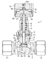
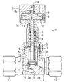
- FIG. 1 is a longitudinal sectional view showing an embodiment in which a valve body according to the present invention is applied to a bellows valve, and shows a closed state.
- FIG. 2 shows the open state of FIG.
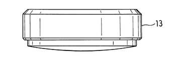
- FIG. 3 is a front view with a part cut away showing the valve body according to the present invention.
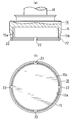
- 4A and 4B are views showing a holding member for a valve body according to the present invention, in which FIG. 4A is a longitudinal sectional view, and FIG. FIG. 5 is a front view showing a contact member of the valve body according to the present invention.
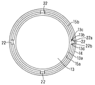
- FIG. 6 is a bottom view schematically showing the caulking state of the valve body according to the present invention.
- FIG. 7 is a longitudinal sectional view showing an embodiment in which the valve body according to the present invention is applied to another valve.
- valve body 1 to 6 show an embodiment of a valve body according to the present invention and a valve provided with the valve body.
- This valve (1) is referred to as a bellows valve, and is provided at the periphery of the valve box (2) provided with the fluid inflow passage (2a) and the fluid outflow passage (2b), and the fluid inflow passage (2a).
- a valve body (3) that opens or closes the fluid inflow passage (2a) by being pressed or separated, a bonnet (4) that is fixed to the upper side of the valve box (2) by a bonnet nut (5), and a valve body (3 ) Is fixed and arranged in the bonnet (4) so as to be movable up and down, a compression coil spring (biasing member) (7) for biasing the valve stem (6) downward, and the bonnet Can be moved up and down in the casing (8) by being provided integrally with the cylindrical casing (8) provided on the upper side of (4) and the valve stem (6) protruding upward from the bonnet (4) And a bellows (10) for preventing fluid from flowing into the valve body (3) side.
- the valve box (2) is made of stainless steel, and has a cylindrical upper protrusion (2c). A male thread portion that is screwed onto the bonnet nut (5) is formed in the upward projecting portion (2c).
- the valve box (2) has an inlet side pipe joint (11) for connecting the fluid inflow passage (2a) and the external pipe, and an outlet side pipe for connecting the fluid outflow passage (2b) and the external pipe. A joint (12) is provided.
- the valve body (3) includes a contact member (13) that contacts the opening edge of the fluid inflow passage (2a) and closes the opening of the fluid inflow passage (2a), and a contact member. And a holding member (14) for holding (13).
- the holding member (14) is made of stainless steel. As shown in FIG. 4, the lower large-diameter shaft portion (15) and the small-diameter shaft portion extending upward from the large-diameter shaft portion (15) ( 16).
- the abutting member (13) is also called a disk packing and is made of synthetic resin, and has a disk shape as shown in FIG.
- the synthetic resin used as the material of the contact member (13) may be, for example, a fluorine-based resin such as PTFE or PFA, and is a PEEK material (polyether ether ketone resin) in order to enhance the corrosiveness against ammonia or the like. May be.
- the large-diameter shaft portion (15) of the holding member (14) is formed in a stepped shape with a large diameter in the lower portion, and opens downward in the lower portion of the large-diameter shaft portion (15).
- a recess (15a) in which the contact member (13) is fitted is formed.
- the upper end portion of the small diameter shaft portion (16) of the holding member (14) is fixed to the lower end portion of the valve stem (6), so that the valve body (3) is integrated with the valve stem (6). Move up and down.
- a bellows fixing ring (17) is fixed to a portion near the upper end of the small diameter shaft portion (16) of the holding member (14), and the large diameter shaft portion (15) of the fixing ring (17) and the holding member (14).
- a bellows (10) is arranged between the upper surface of the two.
- the bellows (10) is manufactured, for example, by punching metal into a disk shape to form a precise corrugated plate and welding the inner and outer peripheries of the corrugated plate.
- the casing (8) is composed of a lower casing (18) and an upper casing (19) connected to the lower casing (18), and includes a bottom wall of the lower casing (18) and a top wall of the upper casing (19).
- An arrangement space for the piston (9) is formed.
- a space between the lower surface of the piston (9) and the bottom wall of the lower casing (18) is a compressed air introduction chamber (20).
- a through passage (19a) for introducing compressed air is formed in the top wall of the upper casing (19).
- the piston (9) has an upper protrusion (9a) that is fitted into the lower end of the through passage (19a), and the piston (9) is compressed by extending downward from the upper end of the upper protrusion (9a).
- a compressed air introduction passage (21) communicating with the air introduction chamber (20) is formed.
- valve (1) When the compressed air is not introduced into the compressed air introduction chamber (20), the valve (1) is pressed against the valve element (3) by the downward biasing force of the compression coil spring (7) as shown in FIG.
- the contact member (13) contacts the opening edge of the fluid inflow passage (2a) and closes the opening of the fluid inflow passage (2a).
- the piston ( 9) When compressed air is introduced into the compressed air introduction chamber (20) via the through passage (19a) on the top wall of the upper casing (19) and the compressed air introduction passage (21) of the piston (9), the piston ( 9)
- the valve stem (6) integral with the piston (9) and the valve body (3) fixed to the valve stem (6) move upward integrally, and as a result, as shown in FIG.
- the through passage (19a) provided in the casing (8) is formed in the top wall of the upper casing (19) here, but this passage is configured on the side wall of the upper casing (19) or the lower casing (18). Of course, it may be done.
- the lower end portion of the peripheral wall (15b) forming the recess (15a) of the large-diameter shaft portion (15) of the holding member (14) is caulked (
- the contact member (13) is held by the holding member (14) by applying a force inward from the outside in the radial direction to be plastically deformed).
- at least one is provided at the lower end portion of the peripheral wall (15b) of the large-diameter shaft portion (15), that is, the caulking portion of the holding member (14).
- the notches (22) are provided at equal intervals in the circumferential direction.
- FIG. 3 when the lower end portion of the peripheral wall (15b) of the large-diameter shaft portion (15) of the holding member (14) is caulked, the abutting member (13) is compressed according to caulking.
- steps (13c) and (13d) are formed in the contact member (13) (exaggerated in the figure), and the wall surface of the notch (22) is formed in the step (13c) and (13d) from the circumferential direction. (22a) (22b) will be engaged.
- the wall surface (22a) on the counterclockwise side of the notch (22) serves as a stopper, and the contact member (13) counterclockwise.
- Engaging the step (13c) on the side and generating anti-rotation force, and against the clockwise rotation of the contact member (13), the wall (22b) on the clockwise side of the notch (22) Becomes a stopper and engages with the step (13d) on the clockwise side of the abutting member (13) to generate an anti-rotation force.
- the contact member (13) is prevented from rotating with respect to the holding member (14).
- the valve body (3) and valve (1) are suitable for use at high temperatures exceeding 140 ° C. Under such a high temperature, the synthetic resin contact member (13) is subjected to a temperature cycle (repetition of high temperature ⁇ low temperature ⁇ high temperature), so that the anti-rotation force due to caulking may decrease at an early stage in the conventional one. There is.
- the valve body (3) has a rotation prevention force function greatly improved by the notch (22), and can prevent the contact member (13) from rotating for a long time even under high temperature.
- the contact member (13) is made of PEEK material, there is a concern that the elastic modulus will decrease at high temperatures. By combining the valve body (3) and PEEK material, it is suitable for high temperature specifications. And can.
- the notch (22) may be any as long as the step (13c) (13d) is formed on the contact member (13) in the caulking state shown in FIG. It is not limited to what you did.
- the notch may be formed in a groove shape on the inner periphery of the peripheral wall (15b) of the large-diameter shaft portion (15) of the holding member (14) so as to leave the outer periphery of the holding member (14).
- valve (1) a bellows valve
- valve body (3) can of course be used even in a valve having no bellows.
- the valve seat that receives the contact member (13) may be provided integrally with the valve box (2), or may be a separate member from the valve box (2).
- FIG. 7 shows an embodiment in which the valve seat (30) is a separate member from the valve box (2).
- the same components as those in FIG. 7 are a separate member from the valve box (2).
- annular valve seat (30) made of synthetic resin is provided in the valve box (2) so as to be positioned at the periphery of the fluid inflow passage (2a).
- the synthetic resin contact member (13) of the valve body (3) opens or closes the fluid inflow passage (2a) by contacting or separating from the annular valve seat (30).
- the synthetic resin contact member (13) contacts the stainless steel valve box (2), whereas in the embodiment shown in FIG. 7, the synthetic resin contact member. (13) contacts the valve seat (30) made of synthetic resin.
- the synthetic resin used as the material for the valve seat (30) may be, for example, a fluorine-based resin such as PTFE or PFA, and is a PEEK material (polyether ether ketone resin) for enhancing the corrosiveness against ammonia. Also good.
- the contact member has anti-rotation performance.
- Valve 1 Valve 2 Valve box 2a Fluid inflow passage 2b Fluid outflow passage 3 Valve element 13 Contact member 14 Holding member 15a Recess 22 Notch 30 Valve seat
Landscapes
- Engineering & Computer Science (AREA)
- General Engineering & Computer Science (AREA)
- Mechanical Engineering (AREA)
- Lift Valve (AREA)
Abstract
Description
2 弁箱
2a 流体流入通路
2b 流体流出通路
3 弁体
13 当接部材
14 保持部材
15a 凹所
22 切欠き
30 弁座
Claims (6)
- 通路開口縁部に当接して通路開口を塞ぐ合成樹脂製当接部材と、当接部材が嵌め入れられている凹所を有する保持部材とからなり、保持部材がかしめられることで当接部材が保持部材に保持される弁体において、保持部材のかしめられる部分に少なくとも1つの切欠きが設けられていることを特徴とする弁体。
- 通路開口縁部に当接して通路開口を塞ぐ合成樹脂製当接部材と、当接部材が嵌め入れられている凹所を有する保持部材とからなり、
保持部材がかしめられることで当接部材が保持部材に保持される弁体において、保持部材のかしめられる部分に少なくとも1つの切欠きが設けられており、
当接部材が保持部材に嵌め入れられる方向での切欠きの位置における当接部材のかしめ前の前記方向に対する垂直断面の外郭線が円であり、該円の中心から、かしめ後の前記断面の外郭線の1点までの距離と、前記中心から前記外郭線の他の1点までの距離が相違することを特徴とする弁体。 - 切欠きは、切り込み、穴、凹みまたは溝であることを特徴とする請求項1または請求項2に記載の弁体。
- 切欠きは、周方向に所要の間隔で複数設けられていることを特徴とする請求項1、請求項2または請求項3に記載の弁体。
- 流体通路が設けられた弁箱と、流体通路を開閉する弁体とを備え、高温での使用に適した弁であって、弁体が請求項1から請求項4のいずれか1項に記載の弁体とされていることを特徴とする高温用弁。
- 流体通路の周縁に、弁箱と別体の環状の合成樹脂製弁座が設けられていることを特徴とする請求項5に記載の高温用弁。
Priority Applications (3)
| Application Number | Priority Date | Filing Date | Title |
|---|---|---|---|
| CN201580002894.0A CN105874251B (zh) | 2014-02-20 | 2015-02-18 | 阀体及高温用阀 |
| KR1020167019420A KR102143570B1 (ko) | 2014-02-20 | 2015-02-18 | 밸브체 및 고온용 밸브 |
| US15/118,212 US10731763B2 (en) | 2014-02-20 | 2015-02-18 | Valve element and high-temperature-oriented valve |
Applications Claiming Priority (2)
| Application Number | Priority Date | Filing Date | Title |
|---|---|---|---|
| JP2014030411A JP6280765B2 (ja) | 2014-02-20 | 2014-02-20 | 弁体および高温用弁 |
| JP2014-030411 | 2014-02-20 |
Publications (1)
| Publication Number | Publication Date |
|---|---|
| WO2015125828A1 true WO2015125828A1 (ja) | 2015-08-27 |
Family
ID=53878328
Family Applications (1)
| Application Number | Title | Priority Date | Filing Date |
|---|---|---|---|
| PCT/JP2015/054456 WO2015125828A1 (ja) | 2014-02-20 | 2015-02-18 | 弁体および高温用弁 |
Country Status (6)
| Country | Link |
|---|---|
| US (1) | US10731763B2 (ja) |
| JP (1) | JP6280765B2 (ja) |
| KR (1) | KR102143570B1 (ja) |
| CN (1) | CN105874251B (ja) |
| TW (1) | TWI644045B (ja) |
| WO (1) | WO2015125828A1 (ja) |
Families Citing this family (6)
| Publication number | Priority date | Publication date | Assignee | Title |
|---|---|---|---|---|
| JP6894667B2 (ja) * | 2016-03-28 | 2021-06-30 | ナブテスコ株式会社 | シール構造、弁及びシール構造の製造方法 |
| CN108119694B (zh) * | 2016-11-28 | 2021-06-01 | 株式会社山田制作所 | 热敏阀的制造方法和热敏阀 |
| CN108119662B (zh) * | 2016-11-28 | 2020-12-25 | 株式会社山田制作所 | 热敏阀和油泵 |
| JP6866042B2 (ja) * | 2017-09-27 | 2021-04-28 | 信越化学工業株式会社 | 液体の吐出方法 |
| DE102020134037A1 (de) * | 2020-12-17 | 2022-06-23 | Arianegroup Gmbh | Ventil für Fluidleitung mit verbesserter Dichtwirkung und Druckbehälter mit verbessertem Ventil |
| DE102022114019A1 (de) | 2022-06-02 | 2023-12-07 | ECO Holding 1 GmbH | Kolben für ein Ventil, elektromagnetisches Ventil und Brennstoffzellensystem |
Citations (7)
| Publication number | Priority date | Publication date | Assignee | Title |
|---|---|---|---|---|
| JPH0126936Y2 (ja) * | 1985-01-18 | 1989-08-11 | ||
| JPH0260772U (ja) * | 1988-10-27 | 1990-05-07 | ||
| JP3020569U (ja) * | 1995-03-30 | 1996-02-02 | 味の素株式会社 | バルブの弁体部構造 |
| JPH08121615A (ja) * | 1994-10-19 | 1996-05-17 | Nabco Ltd | 弁構造 |
| JPH0932934A (ja) * | 1995-07-21 | 1997-02-07 | Cam:Kk | 水栓用のバルブ体 |
| JP2002113539A (ja) * | 2000-10-11 | 2002-04-16 | Yamaho Kogyo Kk | 金属管と継手部材との接合構造 |
| JP2011506822A (ja) * | 2008-02-19 | 2011-03-03 | ロバート ボッシュ ゲーエムベーハー | 流体静力学的ピストン機械用の後退ボール |
Family Cites Families (38)
| Publication number | Priority date | Publication date | Assignee | Title |
|---|---|---|---|---|
| US2735047A (en) * | 1956-02-14 | Antivibration solenoid structure | ||
| US1409127A (en) * | 1920-07-26 | 1922-03-07 | Graham Valve Company | Valve |
| US1485508A (en) * | 1922-05-11 | 1924-03-04 | Ohio Brass Co | Valve |
| US1651942A (en) * | 1927-02-17 | 1927-12-06 | George J Belknap | Valve |
| US2311009A (en) * | 1938-04-18 | 1943-02-16 | Kenneth M Urquhart | Double seated valve |
| US2271391A (en) * | 1940-06-03 | 1942-01-27 | Drake Lewis Driver | Valve |
| US2348548A (en) * | 1942-08-05 | 1944-05-09 | Gustave J Kochler | Fluid valve |
| US2617621A (en) * | 1946-03-29 | 1952-11-11 | Hobbs James Clarence | Valve |
| US2619115A (en) * | 1947-03-22 | 1952-11-25 | John A Dondero | Spring biased relief valve |
| US2740425A (en) * | 1951-06-20 | 1956-04-03 | Frick Co | High capacity, gas tight seating, adjustable safety valve |
| US2861569A (en) * | 1955-04-01 | 1958-11-25 | John H Emerson | Valve apparatus for dispensing gas |
| US3356335A (en) * | 1965-03-31 | 1967-12-05 | Whitey Research Tool Co | Sample cylinder valve |
| US3831900A (en) * | 1969-05-07 | 1974-08-27 | Whitey Research Tool Co | Valve with sealing seat abutting a soft annular ring and stem |
| JPS6426936A (en) | 1987-07-23 | 1989-01-30 | Matsushita Electric Ind Co Ltd | Data processor |
| US5193577A (en) * | 1990-06-25 | 1993-03-16 | Holthuis B.V | Sludge pump valve |
| US5417373A (en) * | 1994-02-10 | 1995-05-23 | Siemens Automotive L.P. | Electromagnet for valves |
| US5450876A (en) * | 1994-05-11 | 1995-09-19 | Marotta Scientific Controls, Inc. | Magnetically linked valve construction |
| US5709369A (en) * | 1996-07-05 | 1998-01-20 | Fisher Controls International, Inc. | Self-aligning valve disc assembly |
| JP3287316B2 (ja) * | 1998-04-23 | 2002-06-04 | トヨタ自動車株式会社 | 慣性圧入方法 |
| FR2834770B1 (fr) * | 2002-01-11 | 2004-06-25 | Gce Sas | Dispositif d'obturation utilisable dans un dispositif de robinet pour bouteille de gaz sous pression |
| JP2003314370A (ja) * | 2002-04-26 | 2003-11-06 | Zama Japan Kk | 開閉弁の弁体およびその製造方法 |
| JP4300345B2 (ja) * | 2002-09-02 | 2009-07-22 | 株式会社フジキン | 制御器 |
| JP2005265032A (ja) * | 2004-03-18 | 2005-09-29 | Hamai Industries Ltd | シート部構造 |
| CN2826095Y (zh) * | 2005-08-15 | 2006-10-11 | 宁波志清实业有限公司 | 一种液化石油气瓶阀 |
| EP1906066A1 (fr) * | 2006-09-28 | 2008-04-02 | Luxembourg Patent Company S.A. | Robinet, notamment pour bouteille de gaz ultra-haute pureté |
| EP2076698B1 (en) * | 2006-10-13 | 2011-01-12 | Parker-Hannifin Corporation | Three-way poppet valve |
| JP2009079623A (ja) * | 2007-09-25 | 2009-04-16 | Jtekt Corp | 弁装置および手動開閉弁装置 |
| JP4510865B2 (ja) * | 2007-10-24 | 2010-07-28 | 株式会社鷺宮製作所 | 通電時閉型電磁弁 |
| US8302622B2 (en) * | 2010-02-24 | 2012-11-06 | Continental Automotive Systems Us, Inc. | Unbalanced inlet fuel tube for a fuel pressure regulator |
| CN202140588U (zh) * | 2011-06-21 | 2012-02-08 | 镇江市华阳机电制造有限公司 | 活动铆接式阀芯 |
| CN102305297A (zh) * | 2011-09-07 | 2012-01-04 | 江苏永兴集团 | 一种高温高压的截止阀 |
| JP5802540B2 (ja) * | 2011-12-15 | 2015-10-28 | 株式会社不二工機 | 複合弁 |
| JPWO2013129140A1 (ja) * | 2012-02-27 | 2015-07-30 | Ckd株式会社 | てこ式切替弁 |
| CN202955217U (zh) * | 2012-12-11 | 2013-05-29 | 四川制动科技股份有限公司 | 一种内铆式体套配合结构 |
| US9709998B2 (en) * | 2013-03-14 | 2017-07-18 | Marshall Excelsior Co. | Pressure regulator |
| WO2014160594A1 (en) * | 2013-03-28 | 2014-10-02 | Borgwarner Inc. | Wastegate ball-valve |
| US9353866B2 (en) * | 2014-04-17 | 2016-05-31 | Caterpillar Inc. | Seal assembly with complementary surface deformations |
| JP6333086B2 (ja) * | 2014-06-26 | 2018-05-30 | 株式会社不二工機 | 三方電磁弁 |
-
2014
- 2014-02-20 JP JP2014030411A patent/JP6280765B2/ja active Active
-
2015
- 2015-02-18 KR KR1020167019420A patent/KR102143570B1/ko active IP Right Grant
- 2015-02-18 CN CN201580002894.0A patent/CN105874251B/zh not_active Expired - Fee Related
- 2015-02-18 US US15/118,212 patent/US10731763B2/en active Active
- 2015-02-18 WO PCT/JP2015/054456 patent/WO2015125828A1/ja active Application Filing
- 2015-02-24 TW TW104105846A patent/TWI644045B/zh active
Patent Citations (7)
| Publication number | Priority date | Publication date | Assignee | Title |
|---|---|---|---|---|
| JPH0126936Y2 (ja) * | 1985-01-18 | 1989-08-11 | ||
| JPH0260772U (ja) * | 1988-10-27 | 1990-05-07 | ||
| JPH08121615A (ja) * | 1994-10-19 | 1996-05-17 | Nabco Ltd | 弁構造 |
| JP3020569U (ja) * | 1995-03-30 | 1996-02-02 | 味の素株式会社 | バルブの弁体部構造 |
| JPH0932934A (ja) * | 1995-07-21 | 1997-02-07 | Cam:Kk | 水栓用のバルブ体 |
| JP2002113539A (ja) * | 2000-10-11 | 2002-04-16 | Yamaho Kogyo Kk | 金属管と継手部材との接合構造 |
| JP2011506822A (ja) * | 2008-02-19 | 2011-03-03 | ロバート ボッシュ ゲーエムベーハー | 流体静力学的ピストン機械用の後退ボール |
Also Published As
| Publication number | Publication date |
|---|---|
| JP2015155714A (ja) | 2015-08-27 |
| KR20160099696A (ko) | 2016-08-22 |
| KR102143570B1 (ko) | 2020-08-12 |
| TWI644045B (zh) | 2018-12-11 |
| JP6280765B2 (ja) | 2018-02-14 |
| CN105874251B (zh) | 2019-05-17 |
| TW201544740A (zh) | 2015-12-01 |
| CN105874251A (zh) | 2016-08-17 |
| US10731763B2 (en) | 2020-08-04 |
| US20170184204A1 (en) | 2017-06-29 |
Similar Documents
| Publication | Publication Date | Title |
|---|---|---|
| WO2015125828A1 (ja) | 弁体および高温用弁 | |
| AU2013215482B2 (en) | Anti-rotation assemblies for use with fluid valves | |
| US10520098B2 (en) | Butterfly-valve seat ring and fixing structure of the same, and eccentric-type butterfly valve | |
| TW201309949A (zh) | 逆止閥 | |
| JP5875694B2 (ja) | バルブ | |
| RU2672223C2 (ru) | Узлы уплотнения, применяемые в жидкостных клапанах | |
| JP7216001B2 (ja) | 弁 | |
| US9395019B2 (en) | Device for sealing a valve | |
| CN104235486A (zh) | 具有一体的密封件的致动器衬套 | |
| RU2626873C2 (ru) | Уплотнительный элемент для трубопроводной арматуры | |
| JP5790674B2 (ja) | リリーフ弁装置 | |
| JP5295861B2 (ja) | 逆止弁 | |
| JP2005321061A (ja) | 高温用弁 | |
| JP6216551B2 (ja) | 圧力作動弁 | |
| US10359119B2 (en) | High pressure valve | |
| RU2445537C1 (ru) | Запорный клапан | |
| JP2622412B2 (ja) | 高圧適用の流体弁 | |
| JP2009243522A (ja) | 安全弁及びシール構造 | |
| US9777854B2 (en) | Safety valve | |
| JP7458019B2 (ja) | 開閉弁装置 | |
| EP3112661A1 (en) | Sealing arrangement | |
| JP6329793B2 (ja) | 逆止弁 | |
| RU2499173C2 (ru) | Металлическое посадочное место для высокотемпературных жидкостных клапанов | |
| US347727A (en) | Valve | |
| CN110005829B (zh) | 阀杆组件、阀塞组件和阀 |
Legal Events
| Date | Code | Title | Description |
|---|---|---|---|
| 121 | Ep: the epo has been informed by wipo that ep was designated in this application |
Ref document number: 15752027 Country of ref document: EP Kind code of ref document: A1 |
|
| ENP | Entry into the national phase |
Ref document number: 20167019420 Country of ref document: KR Kind code of ref document: A |
|
| WWE | Wipo information: entry into national phase |
Ref document number: 15118212 Country of ref document: US |
|
| NENP | Non-entry into the national phase |
Ref country code: DE |
|
| 122 | Ep: pct application non-entry in european phase |
Ref document number: 15752027 Country of ref document: EP Kind code of ref document: A1 |