WO2015125643A1 - アーク溶接電源 - Google Patents
アーク溶接電源 Download PDFInfo
- Publication number
- WO2015125643A1 WO2015125643A1 PCT/JP2015/053496 JP2015053496W WO2015125643A1 WO 2015125643 A1 WO2015125643 A1 WO 2015125643A1 JP 2015053496 W JP2015053496 W JP 2015053496W WO 2015125643 A1 WO2015125643 A1 WO 2015125643A1
- Authority
- WO
- WIPO (PCT)
- Prior art keywords
- feed
- period
- value
- welding
- arc
- Prior art date
Links
Images


Classifications
-
- B—PERFORMING OPERATIONS; TRANSPORTING
- B23—MACHINE TOOLS; METAL-WORKING NOT OTHERWISE PROVIDED FOR
- B23K—SOLDERING OR UNSOLDERING; WELDING; CLADDING OR PLATING BY SOLDERING OR WELDING; CUTTING BY APPLYING HEAT LOCALLY, e.g. FLAME CUTTING; WORKING BY LASER BEAM
- B23K9/00—Arc welding or cutting
- B23K9/10—Other electric circuits therefor; Protective circuits; Remote controls
- B23K9/1006—Power supply
-
- B—PERFORMING OPERATIONS; TRANSPORTING
- B23—MACHINE TOOLS; METAL-WORKING NOT OTHERWISE PROVIDED FOR
- B23K—SOLDERING OR UNSOLDERING; WELDING; CLADDING OR PLATING BY SOLDERING OR WELDING; CUTTING BY APPLYING HEAT LOCALLY, e.g. FLAME CUTTING; WORKING BY LASER BEAM
- B23K9/00—Arc welding or cutting
- B23K9/095—Monitoring or automatic control of welding parameters
- B23K9/0956—Monitoring or automatic control of welding parameters using sensing means, e.g. optical
-
- B—PERFORMING OPERATIONS; TRANSPORTING
- B23—MACHINE TOOLS; METAL-WORKING NOT OTHERWISE PROVIDED FOR
- B23K—SOLDERING OR UNSOLDERING; WELDING; CLADDING OR PLATING BY SOLDERING OR WELDING; CUTTING BY APPLYING HEAT LOCALLY, e.g. FLAME CUTTING; WORKING BY LASER BEAM
- B23K9/00—Arc welding or cutting
- B23K9/06—Arrangements or circuits for starting the arc, e.g. by generating ignition voltage, or for stabilising the arc
- B23K9/073—Stabilising the arc
-
- B—PERFORMING OPERATIONS; TRANSPORTING
- B23—MACHINE TOOLS; METAL-WORKING NOT OTHERWISE PROVIDED FOR
- B23K—SOLDERING OR UNSOLDERING; WELDING; CLADDING OR PLATING BY SOLDERING OR WELDING; CUTTING BY APPLYING HEAT LOCALLY, e.g. FLAME CUTTING; WORKING BY LASER BEAM
- B23K9/00—Arc welding or cutting
- B23K9/09—Arrangements or circuits for arc welding with pulsed current or voltage
- B23K9/091—Arrangements or circuits for arc welding with pulsed current or voltage characterised by the circuits
- B23K9/092—Arrangements or circuits for arc welding with pulsed current or voltage characterised by the circuits characterised by the shape of the pulses produced
-
- B—PERFORMING OPERATIONS; TRANSPORTING
- B23—MACHINE TOOLS; METAL-WORKING NOT OTHERWISE PROVIDED FOR
- B23K—SOLDERING OR UNSOLDERING; WELDING; CLADDING OR PLATING BY SOLDERING OR WELDING; CUTTING BY APPLYING HEAT LOCALLY, e.g. FLAME CUTTING; WORKING BY LASER BEAM
- B23K9/00—Arc welding or cutting
- B23K9/10—Other electric circuits therefor; Protective circuits; Remote controls
- B23K9/1006—Power supply
- B23K9/1043—Power supply characterised by the electric circuit
- B23K9/1056—Power supply characterised by the electric circuit by using digital means
-
- B—PERFORMING OPERATIONS; TRANSPORTING
- B23—MACHINE TOOLS; METAL-WORKING NOT OTHERWISE PROVIDED FOR
- B23K—SOLDERING OR UNSOLDERING; WELDING; CLADDING OR PLATING BY SOLDERING OR WELDING; CUTTING BY APPLYING HEAT LOCALLY, e.g. FLAME CUTTING; WORKING BY LASER BEAM
- B23K9/00—Arc welding or cutting
- B23K9/12—Automatic feeding or moving of electrodes or work for spot or seam welding or cutting
Definitions
- the present invention relates to an arc welding power source for performing welding by periodically repeating forward and reverse feeding of a welding wire.
- a welding wire as a consumable electrode is fed at a constant speed, and an arc is generated between the welding wire and the base material to perform welding.
- the welding wire and the base material are often in a welding state in which a short circuit state and an arc generation state are alternately repeated.
- the short circuit and the arc are repeated at a substantially constant cycle. For this reason, in a small current region, by appropriately controlling the welding current and the welding voltage, welding with a small amount of spatter generation and a good bead appearance can be performed.
- FIG. 8 is a waveform diagram in the welding method in which the feeding speed is periodically forwarded and reversed.
- FIG. 4A shows the waveform of the feeding speed Fw
- FIG. 4B shows the waveform of the welding current Iw
- FIG. 4C shows the waveform of the welding voltage Vw.
- the feed speed Fw is a forward feed period above 0 and a reverse feed period below. Forward feeding is feeding in the direction in which the welding wire is brought closer to the base material, and reverse feeding is feeding in a direction away from the base material.
- the feeding speed Fw changes in a sine wave shape and has a waveform shifted to the forward feeding side. For this reason, the average value of the feeding speed Fw is a positive value, and the welding wire is fed forward on average.
- the feeding speed Fw is 0 at time t1
- the period from time t1 to t2 is the forward acceleration period
- the maximum value of forward feeding at time t2 and the time t2 to
- the period of t3 is the forward deceleration period
- the period of time t3 to t4 is the reverse acceleration period
- the period of time t4 to t5 is the reverse deceleration period It becomes.
- the feeding speed Fw is in the reverse feed period from time t3, so the welding wire is fed backward.
- the short circuit is released by this reverse feed, and the arc is regenerated at time t31.
- the reoccurrence of the arc often occurs before and after the maximum reverse feed value at time t4. In the figure, the case occurs at time t31 during the reverse acceleration period before the reverse peak value.
- the welding voltage Vw When the arc is regenerated at time t31, the welding voltage Vw rapidly increases to an arc voltage value of several tens of volts as shown in FIG. As shown in FIG. 5B, the welding current Iw is rapidly reduced from a time slightly before time t31 by the droplet constriction detection control for detecting a sign of arc reoccurrence, and the arc reoccurrence time at time t31. In, it is a small current value.
- the feeding speed Fw is reversely sent from time t31 to time t5. During this period, the arc length becomes longer.
- the welding current Iw increases at a predetermined slope and maintains that value for a predetermined period when it reaches a predetermined high arc current value. Start decreasing.
- the feeding speed Fw is a forward feeding period from time t5 and becomes a forward feeding peak value at time t6. Then, at time t61, a short circuit occurs. During the period from time t5 to time t61, the welding voltage Vw gradually decreases as shown in FIG. 5C, and the welding current Iw also gradually decreases as shown in FIG.
- the cycle between the short circuit and the arc substantially coincides with the cycle between the forward feed and the reverse feed of the feed speed. That is, in this welding method, the cycle between the short circuit and the arc can be set to a desired value by setting the cycle between the forward feed and the reverse feed of the feed speed. For this reason, in particular, if this welding method is performed in a large current region, it becomes possible to suppress the variation in the cycle between the short circuit and the arc and make it substantially constant, and the amount of spatter generation is small and the bead appearance is reduced. Good welding can be performed.
- the present invention provides an arc welding power source that can suppress stable synchronization between the cycle of the short circuit and the arc and the cycle of the forward feed and the reverse feed of the feed speed and can perform stable welding.
- the purpose is to do.
- the present invention provides: An output control unit that outputs a welding voltage and a welding current corresponding to each of a short circuit period and an arc period;
- the welding wire feed speed is accelerated in the forward feed direction during the forward feed acceleration period, decelerated in the forward feed direction during the forward feed deceleration period, and accelerated in the reverse feed direction during the reverse feed acceleration period, and reverse feed deceleration.
- a feed control unit that decelerates in the reverse feed direction, In arc welding power supply with The feed control unit includes a short-circuit forced generation period between the normal feed acceleration period and the normal feed deceleration period, and during the short-circuit forced generation period, the feed control unit has a higher rate of change than the normal feed acceleration period. Accelerating the feeding speed and maintaining the value when the feeding speed reaches a predetermined forward peak value, This is an arc welding power source.
- the feed control unit accelerates the feed speed at a rate of change larger than the forward feed acceleration period during the reverse feed acceleration period, and the feed speed is a reverse feed peak value determined in advance. To maintain its value when reaching It is characterized by that.
- the feed control unit decelerates the feed speed by a predetermined value from the reverse feed peak value during the reverse feed deceleration period, and then slows down by changing the rate of change. It is characterized by that.
- the feeding control unit includes the short-circuit forced generation period when an average value of the feeding speed is equal to or higher than a predetermined reference feeding speed. It is characterized by that.
- the output control unit reduces the welding current during the arc period to be less than a predetermined reference current value when the feeding speed enters the short-circuit forced generation period. It is characterized by that.
- a short circuit can always be generated during the forced short circuit generation period. For this reason, in this invention, since it can suppress that the period of a short circuit and an arc, and the period of forward feeding and reverse feeding of a feeding speed will be in a synchronous shift state, stable welding can be performed. it can.
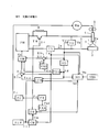
- FIG. 1 is a block diagram of an arc welding power source according to Embodiment 1 of the present invention. Hereinafter, each block will be described with reference to FIG.
- the power supply main circuit PM receives a commercial power supply (not shown) such as a three-phase 200V, performs output control such as inverter control according to an error amplification signal Ea described later, and outputs a welding voltage Vw and a welding current Iw.
- a commercial power supply not shown
- output control such as inverter control according to an error amplification signal Ea described later
- This power supply main circuit PM is omitted in the drawing, but a primary rectifier that rectifies commercial power, a smoothing capacitor that smoothes the rectified direct current, an inverter circuit that converts the smoothed direct current to high frequency alternating current, and high frequency alternating current for welding A high-frequency transformer that steps down the voltage to an appropriate voltage value, a secondary rectifier that rectifies the stepped-down high-frequency alternating current into direct current, a reactor that smoothes the rectified direct current, and modulation that performs pulse width modulation control using the error amplification signal Ea as an input.
- the circuit includes an inverter drive circuit that drives a switching element of the inverter circuit with a pulse width modulation control signal as an input.
- the current reducing resistor R is inserted between the power supply main circuit PM and the welding torch 4.
- the value of the current reducing resistor R is set to a value (about 0.5 to 3 ⁇ ) that is 10 times or more larger than the short-circuit load (about 0.01 to 0.03 ⁇ ). For this reason, when the current reducing resistor R is inserted into the energization path by the constriction detection control, the energy accumulated in the DC reactor in the welding power source and the reactor of the external cable is suddenly discharged.
- the transistor TR is connected in parallel with the current reducing resistor R and is controlled to be turned on or off in accordance with a drive signal Dr described later.
- the feed motor WM receives a feed control signal Fc, which will be described later, and feeds the welding wire 1 at a feed speed Fw by periodically repeating forward feed and reverse feed.
- a feed control signal Fc which will be described later
- Fc feed control signal
- the feeding motor WM may be installed near the tip of the welding torch 4. In some cases, two feed motors WM are used to form a push-pull feed system.
- the welding wire 1 is fed through the welding torch 4 by the rotation of the feeding roll 5 coupled to the feeding motor WM, and an arc 3 is generated between the base metal 2 and the welding wire 1.
- a welding voltage Vw is applied between the power feed tip (not shown) in the welding torch 4 and the base material 2, and a welding current Iw is conducted.
- the welding current detection circuit ID detects the welding current Iw and outputs a welding current detection signal Id.
- the welding voltage detection circuit VD detects the welding voltage Vw and outputs a welding voltage detection signal Vd.
- the short-circuit determination circuit SD receives the welding voltage detection signal Vd as described above, and when this value is less than a predetermined short-circuit / arc determination value (set to about 10 V), determines that it is in the short-circuit period and becomes High level. In the above case, it is determined that the arc period is in effect, and a short-circuit determination signal Sd that goes low is output.
- a predetermined short-circuit / arc determination value set to about 10 V
- the necking detection reference value setting circuit VTN outputs a predetermined necking detection reference value signal Vtn.
- the value of the squeezing detection reference value signal Vtn is set to an appropriate value according to welding conditions such as a welding method, an average welding current value, a material of the welding wire 1 and a diameter.
- the squeezing detection circuit ND receives the squeezing detection reference value signal Vtn, the short circuit determination signal Sd, the welding voltage detection signal Vd, and the welding current detection signal Id, and the short circuit determination signal Sd is at a high level (short circuit period).
- the squeezing detection signal Nd which becomes Low level at the time of changing to () is output. Further, the squeezing detection signal Nd may be changed to a high level when the differential value of the welding voltage detection signal Vd during the short circuit period reaches the value of the squeezing detection reference value signal Vtn corresponding thereto.
- the resistance value of the droplet is calculated by dividing the value of the welding voltage detection signal Vd by the value of the welding current detection signal Id, and the differential value of this resistance value reaches the value of the squeezing detection reference value signal Vtn corresponding thereto. At this point, the squeezing detection signal Nd may be changed to a high level.
- the low level current setting circuit ILR outputs a predetermined low level current setting signal Ilr.
- the current comparison circuit CM receives the low level current setting signal Ilr and the welding current detection signal Id as input, and becomes a high level when Id ⁇ Ilr, and a low level current comparison signal Cm when Id ⁇ Ilr. Is output.
- the drive circuit DR receives the current comparison signal Cm and the above-described squeezing detection signal Nd, changes to a low level when the squeezing detection signal Nd changes to a high level, and then changes to a high level when the current comparison signal Cm changes to a high level.
- the drive signal Dr that changes in level is output to the base terminal of the transistor TR.
- the drive signal Dr becomes a low level
- the transistor TR is turned off, and the current reducing resistor R is inserted into the energization path. Therefore, the welding current Iw for energizing the short-circuit load decreases rapidly.
- the drive signal Dr becomes a high level and the transistor TR is turned on, so that the current reducing resistor R is short-circuited and is normally Return to the state.
- the current control setting circuit ICR receives the short circuit determination signal Sd, the low level current setting signal Ilr, and the squeezing detection signal Nd as input, and outputs the current control setting signal Icr. 1) A predetermined initial current set value is output as the current control setting signal Icr during a predetermined initial period from the time when the short circuit determination signal Sd changes to the high level (short circuit). 2) Thereafter, the value of the current control setting signal Icr is increased from the initial current setting value to a predetermined peak setting value at a predetermined short-circuit slope, and the value is maintained.
- the off-delay circuit TDS receives the short-circuit determination signal Sd as described above, and outputs a delay signal Tds by delaying off the time when this signal changes from the high level to the low level by a predetermined delay time. Therefore, the delay signal Tds is a high level signal during the short circuit period and is a low level signal that is off-delayed by a delay time after the arc is regenerated.
- the current error amplification circuit EI amplifies an error between the current control setting signal Icr (+) and the welding current detection signal Id ( ⁇ ), and outputs a current error amplification signal Ei.
- the voltage setting circuit VR outputs a predetermined voltage setting signal Vr for setting the welding voltage during the arc period.
- the voltage error amplification circuit EV amplifies an error between the voltage setting signal Vr (+) and the welding voltage detection signal Vd ( ⁇ ), and outputs a voltage error amplification signal Ev.
- the control switching circuit SW receives the current error amplification signal Ei, the voltage error amplification signal Ev, and the delay signal Tds as inputs, and the delay signal Tds is at a high level (the arc is regenerated from the start of the short circuit and the delay time is increased).
- the current error amplification signal Ei is output as the error amplification signal Ea during the period until the time elapses, and the voltage error amplification signal Ev is output as the error amplification signal Ea when at the low level (arc).
- constant current control is performed during the short circuit period + delay period, and constant voltage control is performed during the other arc periods.
- the average feed speed setting circuit FAR outputs a predetermined average feed speed setting signal Far.
- the feed speed setting circuit FR receives the average feed speed setting signal Far as an input, and stores a normal feed acceleration period, a short-circuit forced generation period, a normal feed deceleration period stored in correspondence with the average feed speed setting signal Far, A feed speed setting signal Fr of a feed pattern, which will be described later with reference to FIGS. 2A to 4A, formed from the reverse feed acceleration period and the reverse feed deceleration period is output. Therefore, the average value of the feeding patterns stored corresponding to the average feeding speed setting signal Far is equal to the value of the average feeding speed setting signal Far.
- the feed control circuit FC receives the feed speed setting signal Fr and inputs a feed control signal Fc for feeding the welding wire 1 at a feed speed Fw corresponding to the set value to the feed motor WM. Output to.
- the arc welding power source includes an output control unit and a feed control unit.
- the feed control unit includes a feed speed setting circuit FR and a feed control circuit FC.
- the output control unit includes other circuits.
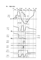
- FIG. 2 is a timing chart of each signal in the arc welding power source described above.
- the figure (A) shows the time change of the feeding speed Fw of the welding wire 1
- the figure (B) shows the time change of the welding current Iw
- the figure (C) shows the time change of the welding voltage Vw
- (D) shows the time change of the squeezing detection signal Nd
- (E) shows the time change of the drive signal Dr
- Dr shows the time change of the delay signal Tds
- G Shows the time change of the current control setting signal Icr.
- the rate of change means the absolute value of the rate of change.
- the feed speed Fw during the predetermined forward feed acceleration period Tsu from time t1 to t2 is accelerated as time elapses from 0, and becomes a predetermined first forward feed value Fs1 at time t2.
- the normal feed acceleration period Tsu is, for example, 5 ms.
- the maximum value of the feed speed Fw is about 15 m / min.
- the first forward feed value Fs1 is a value more than twice, for example, 50 m / min.
- the feed speed Fw during a predetermined short-circuit forced generation period Tsp from time t2 to t3 is accelerated from the first normal feed value Fs1 at a rate of change of 5 times or more larger than that during the normal feed acceleration period Tsu, When a predetermined forward feed peak value Fsp is reached, that value is maintained.
- the short circuit forced generation period Tsp is, for example, 1.5 ms.
- the forward feed peak value Fsp is larger than the first forward feed value Fs1 and is, for example, 100 m / min. The reason for increasing the rate of change is to quickly accelerate to the forward feed peak value Fsp. By maintaining the large forward feed peak value Fsp, the welding wire is quickly short-circuited with the molten pool. That is, a short circuit is forcibly generated.
- the reason why the rate of change is increased is to stabilize the welding state by setting the short-circuit period to a desired value.
- the normal feed deceleration period Tsd is, for example, 1 ms.
- the feed speed Fw during the predetermined reverse feed acceleration period Tru from time t4 to t5 is accelerated in a sine wave form from 0, and reaches a predetermined reverse feed peak value Frp at time t5.
- the reverse acceleration period Tru is 3 ms, for example.
- the reverse feed peak value Frp is, for example, ⁇ 50 m / min.
- the feed speed Fw during the predetermined reverse feed deceleration period Trd from time t5 to t6 is decelerated in a sine wave shape from the reverse feed peak value Frp, and becomes zero at time t6.
- the reverse feed deceleration period Trd is, for example, 3 ms.
- the time t6 to t7 again becomes the normal feed acceleration period Tsu, and the time t7 to t8 again becomes the short circuit forced generation period Tsp. Accordingly, the feeding speed Fw is repeated with the period from time t1 to t6 as one cycle.
- the average value of the feeding speed Fw shown in FIG. 5A corresponds to the feeding speed Fw in general welding that feeds at a constant speed.
- the average value of the feeding speed Fw is always a positive value. In the case of the numerical example described above, the average value of the feeding speed Fw is about 10 m / min (average welding current 300 A).
- the feed speed Fw is accelerated in the forward feed direction as shown in FIG. Since this period is a period in which an arc is generated, a welding current Iw is applied as shown in FIG. 5B, and the welding voltage Vw is an arc of several tens of volts as shown in FIG. It becomes a voltage value.
- the feed speed Fw is rapidly accelerated in the forward feed direction to become a large forward peak value Fsp as shown in FIG.
- the welding wire comes into contact with the base material and enters a short circuit state.
- the welding voltage Vw rapidly decreases to a short circuit voltage value of several volts as shown in FIG.
- the delay signal Tds changes from the Low level to the High level as shown in FIG.
- the current control setting signal Icr changes from a predetermined high level current setting value to a predetermined initial current setting value which is a small value at time t21.
- the current control setting signal Icr becomes the above initial current set value during a predetermined initial period from time t21 to t31, and during a predetermined short circuit during the period from time t31 to t41. It rises with an inclination and becomes a predetermined peak set value during the period from time t41 to t42. Since the constant current control is performed as described above during the short circuit period, the welding current Iw is controlled to a value corresponding to the current control setting signal Icr.
- the welding current Iw rapidly decreases from the welding current during the arc period at time t21, becomes an initial current value during the initial period from time t21 to t31, and reaches from time t31 to t41. During the period, it rises with a slope at the time of short circuit, and reaches a peak value during the period from time t41 to t42.
- the initial period is set to 1 ms
- the initial current is set to 50 A
- the short-circuit slope is set to 400 A / ms
- the peak value is set to 450 A.
- the squeezing detection signal Nd is at a high level during a period from time t42 to t44 described later, and is at a low level during other periods.
- the drive signal Dr is at a low level during a period from time t42 to t43, which will be described later, and is at a high level during other periods. Therefore, during the period before time t42 in the figure, the drive signal Dr is at a high level and the transistor TR in FIG. 1 is turned on, so that the current reducing resistor R is short-circuited and the normal consumable electrode arc welding power source is connected. It becomes the same state.
- the welding voltage Vw increases from around time t41 when the welding current Iw reaches its peak value. This is because a constriction is gradually formed in the droplet due to the reverse feed of the welding wire and the action of the pinch force caused by the welding current Iw.
- the welding voltage Vw rapidly rises, and the voltage rise value ⁇ V from the voltage value during the initial period becomes equal to the predetermined squeezing detection reference value Vtn.
- the squeezing detection signal Nd changes to a high level as shown in FIG.
- the drive signal Dr becomes a low level, so that the transistor TR in FIG. 1 is turned off, and the current reducing resistor R is inserted into the energization path.
- the current control setting signal Icr decreases to the value of the low level current setting signal Ilr. For this reason, as shown in FIG.
- the welding current Iw rapidly decreases from the peak value to the low level current value Il.
- the drive signal Dr returns to the high level, so that the transistor TR in FIG. The device R is short-circuited.
- the welding current Iw maintains the low level current value Il until the arc is regenerated at time t44 because the current control setting signal Icr remains the low level current setting signal Ilr. Therefore, the transistor TR is turned off only during a period from when the constriction is detected at time t42 to when the welding current Iw decreases to the low level current value Il at time t43.
- the welding voltage Vw increases rapidly after once decreasing from time t42 because the welding current Iw becomes small.
- the low level current value Il is set to 50 A, for example.
- the feed speed Fw is reduced while maintaining the reverse feed state, as shown in FIG.
- the value of the current control setting signal Icr rises from the value of the low level current setting signal Ilr with a predetermined arc slope as shown in FIG.
- the delay signal Tds remains at the high level until time t51 when a predetermined delay period Td elapses after the arc is regenerated at time t44. Therefore, since the welding power source is controlled at a constant current until time t51, as shown in FIG.
- the welding current Iw increases at an arc slope from time t44 and reaches that value when it reaches a high level current value. Is maintained until time t51.
- the welding voltage Vw is in a high level voltage value during the delay period Td between times t44 and t51.
- the squeezing detection signal Nd changes to the low level because the arc is regenerated at time t44.
- the arc slope is set to 400 A / ms
- the high level current value is set to 450 A
- the delay period Td is set to 2 ms.
- the delay signal Tds changes to the low level as shown in FIG.
- the welding power source is switched from constant current control to constant voltage control.
- the welding wire is fed backward, so the arc length gradually increases. Since it is the forward feed acceleration period Tsu from time t6, the feed speed Fw is switched to forward feed as shown in FIG.
- the welding current Iw gradually decreases from the high level current value.
- the welding voltage Vw gradually decreases from the high level voltage value.
- the welding current Iw is rapidly reduced by inserting a current reducing resistor in the energizing path, and the current value at the time when the arc is regenerated at time t44 is obtained. It can be controlled to a small value. For this reason, the amount of spatter generated can be greatly reduced.
- the short circuit always occurs during the short circuit forced generation period Tsp.
- the arc occurs during the reverse acceleration period Tru before the time t5 is illustrated in the same figure, it may occur during the reverse deceleration period Trd after the time t5.
- a short-circuit forced generation period is provided between the normal-feed acceleration period and the normal-feed deceleration period, and during this short-circuit forced generation period, feeding is performed at a larger change rate than during the normal-feed acceleration period.
- the speed is accelerated, and when the feeding speed reaches a predetermined forward feed peak value, the value is maintained.
- the block diagram of the arc welding power source according to the second embodiment is the same as FIG. However, the difference is that the feeding pattern of the feeding speed preset in the feeding speed setting circuit FR is as shown in FIG.
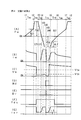
- FIG. 3 is a timing chart of each signal in the arc welding power source according to Embodiment 2 of the present invention.
- the figure (A) shows the time change of the feeding speed Fw of the welding wire 1
- the figure (B) shows the time change of the welding current Iw
- the figure (C) shows the time change of the welding voltage Vw
- (D) shows the time change of the squeezing detection signal Nd
- (E) shows the time change of the drive signal Dr
- (F) shows the time change of the delay signal Tds
- G Shows the time change of the current control setting signal Icr.
- This figure corresponds to FIG. 2 described above, and the description of the same operation will not be repeated.
- different operations will be described with reference to FIG.
- the feed pattern of the feed speed Fw shown in FIG. 4A is different from FIG. 2 only in the change during the reverse feed acceleration period Tru from time t4 to t5.
- the feed speed Fw during the predetermined reverse feed acceleration period Tru from time t4 to t5 is accelerated in the reverse feed direction from 0 to a predetermined reverse feed peak at a larger change rate than during the forward feed acceleration period Tsu.
- the reverse acceleration period Tru is, for example, 2.5 ms.
- the reverse feed peak value Frp is, for example, ⁇ 50 m / min. By increasing the rate of change, the reverse peak value Frp is reached quickly. By doing so, it is possible to concentrate the arc re-generation timing during the period in which the reverse peak value Frp is maintained.
- the feed speed Fw is switched to the reverse feed state, and is accelerated rapidly with a larger change rate than during the forward feed acceleration period Tsu.
- the reverse peak value Frp is reached, the value is maintained.
- the welding current Iw rapidly decreases from the welding current during the arc period at time t21, becomes an initial current value during the initial period from time t21 to t31, and is short-circuited during the period from time t31 to t41. It rises with a time slope and reaches a peak value during the period from time t41 to t42.
- the feed speed is accelerated at a rate of change larger than that in the normal feed acceleration period, and when the feed speed reaches a predetermined reverse feed peak value, the value is reached.
- the reverse feed peak value is quickly reached by increasing the rate of change of the feed speed at the rise of the reverse feed acceleration period. By doing so, it is possible to concentrate the arc regeneration timing during the period in which the reverse peak value is maintained. For this reason, in the second embodiment, it is possible to further stabilize the synchronization state of the cycle of the short circuit and the arc and the cycle of the forward feed and the reverse feed of the feed speed.
- the block diagram of the arc welding power source according to Embodiment 3 is the same as FIG. However, the difference is that the feeding pattern of the feeding speed preset in the feeding speed setting circuit FR is as shown in FIG.
- FIG. 4 is a timing chart of each signal in the arc welding power source according to Embodiment 3 of the present invention.
- the figure (A) shows the time change of the feeding speed Fw of the welding wire 1
- the figure (B) shows the time change of the welding current Iw
- the figure (C) shows the time change of the welding voltage Vw
- (D) shows the time change of the squeezing detection signal Nd
- (E) shows the time change of the drive signal Dr
- (F) shows the time change of the delay signal Tds
- G Shows the time change of the current control setting signal Icr.
- This figure corresponds to FIG. 3 described above, and the description of the same operation will not be repeated.
- different operations will be described with reference to FIG.
- the feed pattern of the feed speed Fw shown in FIG. 9A is different from FIG. 3 only in the change during the reverse feed deceleration period Trd from time t5 to t6.
- the feed speed Fw during the predetermined reverse feed deceleration period Trd from time t5 to t6 is decelerated by a predetermined value ⁇ F from the reverse feed peak value Frp, and thereafter, the rate of change is reduced and the speed is reduced.
- ⁇ F from the reverse feed peak value Frp
- the feed speed Fw is decelerated from the reverse feed peak value Frp by a predetermined value ⁇ F, and thereafter the rate of change is reduced. Slow down.
- the welding current Iw rises at an arc slope from time t44 when the arc is regenerated, and when the arc reaches a high level current value, the value is maintained until time t51. Therefore, during the reverse feed deceleration period Trd, since the welding wire is sent back in a state where an arc is generated, the arc length is increased. At the same time, the tip of the welding wire is melted and the droplets gradually increase.
- the feed speed is decelerated by a predetermined value from the reverse feed peak value, and thereafter, the rate of change is reduced to reduce the speed.
- the rate of change is reduced to reduce the speed.
- the invention of the fourth embodiment includes a short-circuit forced generation period when the average value of the feeding speed is equal to or higher than a predetermined reference feeding speed. That is, the short-circuit forced generation period is not provided when the average value of the feeding speed is less than the reference feeding speed, and is provided only when the average value is above.
- FIG. 5 is a block diagram of an arc welding power source according to Embodiment 4 of the present invention. This figure corresponds to FIG. 1 described above, and the same reference numerals are given to the same blocks and their description will not be repeated.
- the feeding speed setting circuit FR of FIG. 1 is replaced with a second feeding speed setting circuit FR2.
- this block will be described with reference to FIG.
- the second feeding speed setting circuit FR2 receives the average feeding speed setting signal Far, performs the following processing, and outputs a feeding speed setting signal Fr. 1) When the value of the average feed speed setting signal Far is less than a predetermined reference feed speed, the normal feed acceleration period, the normal feed deceleration period stored in correspondence with the average feed speed setting signal Far, The feed speed setting signal Fr of the feed pattern described above with reference to FIG. 8A formed from the reverse feed acceleration period and the reverse feed deceleration period is output.
- the above-mentioned reference feed speed is set to a value that divides a small current region in which the cycle variation between the short circuit period and the arc period is small and a large current region in which the cycle varies.
- the welding wire is a steel wire and its diameter is 1.2 mm, it is set to 4 m / min.
- the short-circuit forced generation period is provided when the average value of the feeding speed is equal to or higher than a predetermined reference feeding speed.
- the invention of the fourth embodiment has the following effects in addition to the effects of the first to third embodiments.
- spatter may increase depending on the workpiece.
- the short-circuit and arc cycles and the feed-rate forward and reverse cycles rarely go out of synchronization, so there is no need to provide a short-circuit forced generation period. There are many.
- FIG. 6 is a block diagram of an arc welding power source according to Embodiment 5 of the present invention. This figure corresponds to FIG. 1 described above, and the same reference numerals are given to the same blocks and their description will not be repeated.
- the voltage setting circuit VR of FIG. 1 is replaced with a second voltage setting circuit VR2.
- this block will be described with reference to FIG.
- the second voltage setting circuit VR2 receives the feed speed setting signal Fr as input and determines whether or not it is in the short circuit forced generation period from the value of the feed speed setting signal Fr.
- a voltage setting signal Vr having a low voltage setting value set in advance to a value smaller than the voltage setting value is output when the voltage setting signal Vr is a value.
- the low voltage set value is set so that the welding current during the arc period is less than a predetermined reference current value.
- the reference current value is set to 100 A, for example.
- FIG. 7 is a timing chart of each signal in the arc welding power source described above with reference to FIG.
- the figure (A) shows the time change of the feeding speed Fw of the welding wire 1
- the figure (B) shows the time change of the welding current Iw
- the figure (C) shows the time change of the welding voltage Vw
- (D) shows the time change of the squeezing detection signal Nd
- (E) shows the time change of the drive signal Dr
- (F) shows the time change of the delay signal Tds
- G Shows the time change of the current control setting signal Icr.
- This figure corresponds to FIG. 2 described above, and the operation during the period other than the times t2 to t21 is the same, and therefore the description thereof will not be repeated.
- different operations will be described with reference to FIG.
- the voltage setting signal Vr is set to a predetermined low voltage setting value by the second voltage setting circuit VR2 in FIG. Can be switched to.
- the welding voltage Vw decreases rapidly and becomes a small value.
- the welding current Iw also decreases rapidly, and becomes a small value less than a predetermined reference current value.
- the fifth embodiment when the feeding speed enters the forcible short-circuit generation period, the welding current during the arc period is decreased to a value less than a predetermined reference current value.
- the fifth embodiment provides the following effects in addition to the effects of the first to fourth embodiments.
- the fifth embodiment by setting the welding current during the arc period of the short circuit forced generation period to a small value, a short circuit is more likely to occur, and spattering when a short circuit occurs can be reduced. If the period during which the welding current is maintained at a small value during the arc period becomes too long, the bead appearance deteriorates.
- the decrease period does not become so long as to affect the bead appearance.
- a short circuit can always be generated during the forced short circuit generation period. For this reason, in this invention, since it can suppress that the period of a short circuit and an arc, and the period of forward feeding and reverse feeding of a feeding speed will be in a synchronous shift state, stable welding can be performed. it can.
Landscapes
- Engineering & Computer Science (AREA)
- Physics & Mathematics (AREA)
- Plasma & Fusion (AREA)
- Mechanical Engineering (AREA)
- Arc Welding Control (AREA)
Priority Applications (5)
| Application Number | Priority Date | Filing Date | Title |
|---|---|---|---|
| KR1020167015108A KR102178235B1 (ko) | 2014-02-18 | 2015-02-09 | 아크 용접 전원 |
| CN201580002825.XA CN105792974B (zh) | 2014-02-18 | 2015-02-09 | 电弧焊接电源 |
| JP2016504041A JP6472435B2 (ja) | 2014-02-18 | 2015-02-09 | アーク溶接電源 |
| EP15752546.0A EP3108989B1 (en) | 2014-02-18 | 2015-02-09 | Arc-welding power supply |
| US15/113,502 US10406622B2 (en) | 2014-02-18 | 2015-02-09 | Arc-welding power supply |
Applications Claiming Priority (2)
| Application Number | Priority Date | Filing Date | Title |
|---|---|---|---|
| JP2014-028675 | 2014-02-18 | ||
| JP2014028675 | 2014-02-18 |
Publications (1)
| Publication Number | Publication Date |
|---|---|
| WO2015125643A1 true WO2015125643A1 (ja) | 2015-08-27 |
Family
ID=53878149
Family Applications (1)
| Application Number | Title | Priority Date | Filing Date |
|---|---|---|---|
| PCT/JP2015/053496 WO2015125643A1 (ja) | 2014-02-18 | 2015-02-09 | アーク溶接電源 |
Country Status (6)
| Country | Link |
|---|---|
| US (1) | US10406622B2 (zh) |
| EP (1) | EP3108989B1 (zh) |
| JP (1) | JP6472435B2 (zh) |
| KR (1) | KR102178235B1 (zh) |
| CN (1) | CN105792974B (zh) |
| WO (1) | WO2015125643A1 (zh) |
Cited By (1)
| Publication number | Priority date | Publication date | Assignee | Title |
|---|---|---|---|---|
| CN106552984A (zh) * | 2015-09-28 | 2017-04-05 | 株式会社达谊恒 | 正反进给交流电弧焊接方法 |
Families Citing this family (6)
| Publication number | Priority date | Publication date | Assignee | Title |
|---|---|---|---|---|
| CN110076415B (zh) * | 2018-01-26 | 2021-11-19 | 株式会社达谊恒 | 电弧焊接控制方法 |
| CN108637434B (zh) * | 2018-05-15 | 2021-01-19 | 深圳市瑞凌实业股份有限公司 | 气保焊机智能低飞溅fasw控制系统及方法 |
| JP7039413B2 (ja) * | 2018-07-26 | 2022-03-22 | 株式会社ダイヘン | アーク溶接制御方法 |
| US20200246902A1 (en) * | 2019-01-31 | 2020-08-06 | Illinois Tool Works Inc. | Systems and methods for controlled arc and short phase time adjustment |
| JP2020131200A (ja) * | 2019-02-13 | 2020-08-31 | 株式会社ダイヘン | アーク溶接方法 |
| CN110554289B (zh) * | 2019-10-14 | 2021-06-08 | 河南理工大学 | 一种低压串联故障电弧检测系统 |
Citations (3)
| Publication number | Priority date | Publication date | Assignee | Title |
|---|---|---|---|---|
| US20060016792A1 (en) * | 2004-06-04 | 2006-01-26 | Uecker James L | Welding arc stabilization process |
| JP2012006020A (ja) * | 2010-06-22 | 2012-01-12 | Daihen Corp | アーク溶接制御方法 |
| WO2012164833A1 (ja) * | 2011-06-03 | 2012-12-06 | パナソニック株式会社 | アーク溶接制御方法およびアーク溶接装置 |
Family Cites Families (10)
| Publication number | Priority date | Publication date | Assignee | Title |
|---|---|---|---|---|
| JPS487474Y1 (zh) | 1969-07-17 | 1973-02-26 | ||
| US4546234A (en) * | 1983-08-11 | 1985-10-08 | Kabushiki Kaisha Kobe Seiko Sho | Output control of short circuit welding power source |
| JPH01157771A (ja) * | 1987-12-16 | 1989-06-21 | Matsushita Electric Ind Co Ltd | 消耗電極式アーク溶接装置の制御方法ならびに制御装置 |
| JP3075263B2 (ja) * | 1998-06-17 | 2000-08-14 | 松下電器産業株式会社 | パルス出力制御方法及び消耗電極式パルスアーク溶接装置 |
| US6531684B2 (en) * | 2001-06-19 | 2003-03-11 | Illinois Tool Works Inc. | Method and apparatus for welding and control |
| AUPS274002A0 (en) * | 2002-06-03 | 2002-06-20 | University Of Wollongong, The | Control method and system for metal arc welding |
| JP4211793B2 (ja) * | 2006-02-17 | 2009-01-21 | パナソニック株式会社 | アーク溶接制御方法およびアーク溶接装置 |
| CN102149501B (zh) | 2009-06-19 | 2013-03-20 | 松下电器产业株式会社 | 消耗电极式电弧焊接方法及消耗电极式电弧焊接装置 |
| CN104722885B (zh) * | 2009-07-29 | 2017-04-12 | 松下电器产业株式会社 | 电弧焊接方法以及电弧焊接装置 |
| US9162308B2 (en) * | 2010-10-22 | 2015-10-20 | Lincoln Global, Inc. | Apparatus and method for pulse welding with AC waveform |
-
2015
- 2015-02-09 JP JP2016504041A patent/JP6472435B2/ja active Active
- 2015-02-09 KR KR1020167015108A patent/KR102178235B1/ko active IP Right Grant
- 2015-02-09 EP EP15752546.0A patent/EP3108989B1/en active Active
- 2015-02-09 US US15/113,502 patent/US10406622B2/en active Active
- 2015-02-09 CN CN201580002825.XA patent/CN105792974B/zh active Active
- 2015-02-09 WO PCT/JP2015/053496 patent/WO2015125643A1/ja active Application Filing
Patent Citations (3)
| Publication number | Priority date | Publication date | Assignee | Title |
|---|---|---|---|---|
| US20060016792A1 (en) * | 2004-06-04 | 2006-01-26 | Uecker James L | Welding arc stabilization process |
| JP2012006020A (ja) * | 2010-06-22 | 2012-01-12 | Daihen Corp | アーク溶接制御方法 |
| WO2012164833A1 (ja) * | 2011-06-03 | 2012-12-06 | パナソニック株式会社 | アーク溶接制御方法およびアーク溶接装置 |
Cited By (2)
| Publication number | Priority date | Publication date | Assignee | Title |
|---|---|---|---|---|
| CN106552984A (zh) * | 2015-09-28 | 2017-04-05 | 株式会社达谊恒 | 正反进给交流电弧焊接方法 |
| CN106552984B (zh) * | 2015-09-28 | 2020-07-07 | 株式会社达谊恒 | 正反进给交流电弧焊接方法 |
Also Published As
| Publication number | Publication date |
|---|---|
| EP3108989B1 (en) | 2019-04-03 |
| JPWO2015125643A1 (ja) | 2017-03-30 |
| KR20160119054A (ko) | 2016-10-12 |
| EP3108989A1 (en) | 2016-12-28 |
| US10406622B2 (en) | 2019-09-10 |
| US20170008115A1 (en) | 2017-01-12 |
| CN105792974A (zh) | 2016-07-20 |
| KR102178235B1 (ko) | 2020-11-12 |
| CN105792974B (zh) | 2019-09-06 |
| EP3108989A4 (en) | 2017-11-08 |
| JP6472435B2 (ja) | 2019-02-20 |
Similar Documents
| Publication | Publication Date | Title |
|---|---|---|
| JP6472435B2 (ja) | アーク溶接電源 | |
| JP6472436B2 (ja) | アーク溶接制御方法 | |
| JP6555818B2 (ja) | アーク溶接制御方法 | |
| KR102213614B1 (ko) | 아크 용접 제어 방법 | |
| JP6448622B2 (ja) | アーク溶接制御方法 | |
| JP6472387B2 (ja) | アーク溶接制御方法 | |
| JP2017013088A (ja) | 正逆送給アーク溶接方法 | |
| WO2016080166A1 (ja) | アーク溶接制御方法 | |
| JP6555825B2 (ja) | アーク溶接制御方法 | |
| KR20170034882A (ko) | 아크 용접 제어 방법 | |
| WO2018131345A1 (ja) | 正逆送給アーク溶接のアークスタート制御方法 | |
| JP6396162B2 (ja) | アーク溶接制御方法 | |
| JP2016144820A (ja) | アーク溶接制御方法 | |
| JP6340295B2 (ja) | アーク溶接制御方法 | |
| JP6347721B2 (ja) | アーク溶接制御方法 | |
| WO2015166793A1 (ja) | アーク溶接制御方法 | |
| JP6261614B2 (ja) | アーク溶接制御方法 | |
| JP6341610B2 (ja) | アーク溶接制御方法 | |
| KR102233253B1 (ko) | 아크 용접 제어 방법 | |
| JP6377427B2 (ja) | アーク溶接制御方法 | |
| JP2016215256A (ja) | 正逆送給アーク溶接方法 |
Legal Events
| Date | Code | Title | Description |
|---|---|---|---|
| 121 | Ep: the epo has been informed by wipo that ep was designated in this application |
Ref document number: 15752546 Country of ref document: EP Kind code of ref document: A1 |
|
| ENP | Entry into the national phase |
Ref document number: 2016504041 Country of ref document: JP Kind code of ref document: A |
|
| ENP | Entry into the national phase |
Ref document number: 20167015108 Country of ref document: KR Kind code of ref document: A |
|
| WWE | Wipo information: entry into national phase |
Ref document number: 15113502 Country of ref document: US |
|
| REEP | Request for entry into the european phase |
Ref document number: 2015752546 Country of ref document: EP |
|
| WWE | Wipo information: entry into national phase |
Ref document number: 2015752546 Country of ref document: EP |
|
| NENP | Non-entry into the national phase |
Ref country code: DE |