WO2015122074A1 - Programme et dispositif de régulation de demande - Google Patents
Programme et dispositif de régulation de demande Download PDFInfo
- Publication number
- WO2015122074A1 WO2015122074A1 PCT/JP2014/080709 JP2014080709W WO2015122074A1 WO 2015122074 A1 WO2015122074 A1 WO 2015122074A1 JP 2014080709 W JP2014080709 W JP 2014080709W WO 2015122074 A1 WO2015122074 A1 WO 2015122074A1
- Authority
- WO
- WIPO (PCT)
- Prior art keywords
- power
- group
- demand
- amount
- target
- Prior art date
Links
Images


Classifications
-
- H—ELECTRICITY
- H02—GENERATION; CONVERSION OR DISTRIBUTION OF ELECTRIC POWER
- H02J—CIRCUIT ARRANGEMENTS OR SYSTEMS FOR SUPPLYING OR DISTRIBUTING ELECTRIC POWER; SYSTEMS FOR STORING ELECTRIC ENERGY
- H02J3/00—Circuit arrangements for ac mains or ac distribution networks
- H02J3/003—Load forecast, e.g. methods or systems for forecasting future load demand
-
- F—MECHANICAL ENGINEERING; LIGHTING; HEATING; WEAPONS; BLASTING
- F24—HEATING; RANGES; VENTILATING
- F24F—AIR-CONDITIONING; AIR-HUMIDIFICATION; VENTILATION; USE OF AIR CURRENTS FOR SCREENING
- F24F11/00—Control or safety arrangements
- F24F11/30—Control or safety arrangements for purposes related to the operation of the system, e.g. for safety or monitoring
- F24F11/46—Improving electric energy efficiency or saving
- F24F11/47—Responding to energy costs
-
- F—MECHANICAL ENGINEERING; LIGHTING; HEATING; WEAPONS; BLASTING
- F24—HEATING; RANGES; VENTILATING
- F24F—AIR-CONDITIONING; AIR-HUMIDIFICATION; VENTILATION; USE OF AIR CURRENTS FOR SCREENING
- F24F11/00—Control or safety arrangements
- F24F11/50—Control or safety arrangements characterised by user interfaces or communication
- F24F11/61—Control or safety arrangements characterised by user interfaces or communication using timers
-
- F—MECHANICAL ENGINEERING; LIGHTING; HEATING; WEAPONS; BLASTING
- F24—HEATING; RANGES; VENTILATING
- F24F—AIR-CONDITIONING; AIR-HUMIDIFICATION; VENTILATION; USE OF AIR CURRENTS FOR SCREENING
- F24F11/00—Control or safety arrangements
- F24F11/62—Control or safety arrangements characterised by the type of control or by internal processing, e.g. using fuzzy logic, adaptive control or estimation of values
- F24F11/63—Electronic processing
- F24F11/65—Electronic processing for selecting an operating mode
-
- G—PHYSICS
- G05—CONTROLLING; REGULATING
- G05B—CONTROL OR REGULATING SYSTEMS IN GENERAL; FUNCTIONAL ELEMENTS OF SUCH SYSTEMS; MONITORING OR TESTING ARRANGEMENTS FOR SUCH SYSTEMS OR ELEMENTS
- G05B11/00—Automatic controllers
- G05B11/01—Automatic controllers electric
-
- G—PHYSICS
- G05—CONTROLLING; REGULATING
- G05B—CONTROL OR REGULATING SYSTEMS IN GENERAL; FUNCTIONAL ELEMENTS OF SUCH SYSTEMS; MONITORING OR TESTING ARRANGEMENTS FOR SUCH SYSTEMS OR ELEMENTS
- G05B13/00—Adaptive control systems, i.e. systems automatically adjusting themselves to have a performance which is optimum according to some preassigned criterion
- G05B13/02—Adaptive control systems, i.e. systems automatically adjusting themselves to have a performance which is optimum according to some preassigned criterion electric
- G05B13/0205—Adaptive control systems, i.e. systems automatically adjusting themselves to have a performance which is optimum according to some preassigned criterion electric not using a model or a simulator of the controlled system
- G05B13/021—Adaptive control systems, i.e. systems automatically adjusting themselves to have a performance which is optimum according to some preassigned criterion electric not using a model or a simulator of the controlled system in which a variable is automatically adjusted to optimise the performance
-
- G—PHYSICS
- G05—CONTROLLING; REGULATING
- G05B—CONTROL OR REGULATING SYSTEMS IN GENERAL; FUNCTIONAL ELEMENTS OF SUCH SYSTEMS; MONITORING OR TESTING ARRANGEMENTS FOR SUCH SYSTEMS OR ELEMENTS
- G05B19/00—Programme-control systems
- G05B19/02—Programme-control systems electric
- G05B19/04—Programme control other than numerical control, i.e. in sequence controllers or logic controllers
- G05B19/042—Programme control other than numerical control, i.e. in sequence controllers or logic controllers using digital processors
-
- H—ELECTRICITY
- H02—GENERATION; CONVERSION OR DISTRIBUTION OF ELECTRIC POWER
- H02J—CIRCUIT ARRANGEMENTS OR SYSTEMS FOR SUPPLYING OR DISTRIBUTING ELECTRIC POWER; SYSTEMS FOR STORING ELECTRIC ENERGY
- H02J3/00—Circuit arrangements for ac mains or ac distribution networks
- H02J3/12—Circuit arrangements for ac mains or ac distribution networks for adjusting voltage in ac networks by changing a characteristic of the network load
- H02J3/14—Circuit arrangements for ac mains or ac distribution networks for adjusting voltage in ac networks by changing a characteristic of the network load by switching loads on to, or off from, network, e.g. progressively balanced loading
-
- H—ELECTRICITY
- H02—GENERATION; CONVERSION OR DISTRIBUTION OF ELECTRIC POWER
- H02J—CIRCUIT ARRANGEMENTS OR SYSTEMS FOR SUPPLYING OR DISTRIBUTING ELECTRIC POWER; SYSTEMS FOR STORING ELECTRIC ENERGY
- H02J4/00—Circuit arrangements for mains or distribution networks not specified as ac or dc
-
- F—MECHANICAL ENGINEERING; LIGHTING; HEATING; WEAPONS; BLASTING
- F24—HEATING; RANGES; VENTILATING
- F24F—AIR-CONDITIONING; AIR-HUMIDIFICATION; VENTILATION; USE OF AIR CURRENTS FOR SCREENING
- F24F11/00—Control or safety arrangements
- F24F11/30—Control or safety arrangements for purposes related to the operation of the system, e.g. for safety or monitoring
- F24F11/46—Improving electric energy efficiency or saving
-
- F—MECHANICAL ENGINEERING; LIGHTING; HEATING; WEAPONS; BLASTING
- F24—HEATING; RANGES; VENTILATING
- F24F—AIR-CONDITIONING; AIR-HUMIDIFICATION; VENTILATION; USE OF AIR CURRENTS FOR SCREENING
- F24F11/00—Control or safety arrangements
- F24F11/62—Control or safety arrangements characterised by the type of control or by internal processing, e.g. using fuzzy logic, adaptive control or estimation of values
- F24F11/63—Electronic processing
-
- F—MECHANICAL ENGINEERING; LIGHTING; HEATING; WEAPONS; BLASTING
- F24—HEATING; RANGES; VENTILATING
- F24F—AIR-CONDITIONING; AIR-HUMIDIFICATION; VENTILATION; USE OF AIR CURRENTS FOR SCREENING
- F24F2110/00—Control inputs relating to air properties
-
- F—MECHANICAL ENGINEERING; LIGHTING; HEATING; WEAPONS; BLASTING
- F24—HEATING; RANGES; VENTILATING
- F24F—AIR-CONDITIONING; AIR-HUMIDIFICATION; VENTILATION; USE OF AIR CURRENTS FOR SCREENING
- F24F2130/00—Control inputs relating to environmental factors not covered by group F24F2110/00
-
- F—MECHANICAL ENGINEERING; LIGHTING; HEATING; WEAPONS; BLASTING
- F24—HEATING; RANGES; VENTILATING
- F24F—AIR-CONDITIONING; AIR-HUMIDIFICATION; VENTILATION; USE OF AIR CURRENTS FOR SCREENING
- F24F2130/00—Control inputs relating to environmental factors not covered by group F24F2110/00
- F24F2130/10—Weather information or forecasts
-
- F—MECHANICAL ENGINEERING; LIGHTING; HEATING; WEAPONS; BLASTING
- F24—HEATING; RANGES; VENTILATING
- F24F—AIR-CONDITIONING; AIR-HUMIDIFICATION; VENTILATION; USE OF AIR CURRENTS FOR SCREENING
- F24F2140/00—Control inputs relating to system states
- F24F2140/50—Load
-
- F—MECHANICAL ENGINEERING; LIGHTING; HEATING; WEAPONS; BLASTING
- F24—HEATING; RANGES; VENTILATING
- F24F—AIR-CONDITIONING; AIR-HUMIDIFICATION; VENTILATION; USE OF AIR CURRENTS FOR SCREENING
- F24F2140/00—Control inputs relating to system states
- F24F2140/60—Energy consumption
-
- G—PHYSICS
- G05—CONTROLLING; REGULATING
- G05B—CONTROL OR REGULATING SYSTEMS IN GENERAL; FUNCTIONAL ELEMENTS OF SUCH SYSTEMS; MONITORING OR TESTING ARRANGEMENTS FOR SUCH SYSTEMS OR ELEMENTS
- G05B2219/00—Program-control systems
- G05B2219/30—Nc systems
- G05B2219/35—Nc in input of data, input till input file format
- G05B2219/35212—Estimating a cost associated with each operation, amount of time, target cost
-
- G—PHYSICS
- G05—CONTROLLING; REGULATING
- G05B—CONTROL OR REGULATING SYSTEMS IN GENERAL; FUNCTIONAL ELEMENTS OF SUCH SYSTEMS; MONITORING OR TESTING ARRANGEMENTS FOR SUCH SYSTEMS OR ELEMENTS
- G05B2219/00—Program-control systems
- G05B2219/30—Nc systems
- G05B2219/35—Nc in input of data, input till input file format
- G05B2219/35215—Generate optimal nc program variant as function of cost, time, surface, energy
-
- H—ELECTRICITY
- H02—GENERATION; CONVERSION OR DISTRIBUTION OF ELECTRIC POWER
- H02J—CIRCUIT ARRANGEMENTS OR SYSTEMS FOR SUPPLYING OR DISTRIBUTING ELECTRIC POWER; SYSTEMS FOR STORING ELECTRIC ENERGY
- H02J2310/00—The network for supplying or distributing electric power characterised by its spatial reach or by the load
- H02J2310/10—The network having a local or delimited stationary reach
- H02J2310/12—The local stationary network supplying a household or a building
- H02J2310/14—The load or loads being home appliances
-
- Y—GENERAL TAGGING OF NEW TECHNOLOGICAL DEVELOPMENTS; GENERAL TAGGING OF CROSS-SECTIONAL TECHNOLOGIES SPANNING OVER SEVERAL SECTIONS OF THE IPC; TECHNICAL SUBJECTS COVERED BY FORMER USPC CROSS-REFERENCE ART COLLECTIONS [XRACs] AND DIGESTS
- Y02—TECHNOLOGIES OR APPLICATIONS FOR MITIGATION OR ADAPTATION AGAINST CLIMATE CHANGE
- Y02B—CLIMATE CHANGE MITIGATION TECHNOLOGIES RELATED TO BUILDINGS, e.g. HOUSING, HOUSE APPLIANCES OR RELATED END-USER APPLICATIONS
- Y02B70/00—Technologies for an efficient end-user side electric power management and consumption
- Y02B70/30—Systems integrating technologies related to power network operation and communication or information technologies for improving the carbon footprint of the management of residential or tertiary loads, i.e. smart grids as climate change mitigation technology in the buildings sector, including also the last stages of power distribution and the control, monitoring or operating management systems at local level
- Y02B70/3225—Demand response systems, e.g. load shedding, peak shaving
-
- Y—GENERAL TAGGING OF NEW TECHNOLOGICAL DEVELOPMENTS; GENERAL TAGGING OF CROSS-SECTIONAL TECHNOLOGIES SPANNING OVER SEVERAL SECTIONS OF THE IPC; TECHNICAL SUBJECTS COVERED BY FORMER USPC CROSS-REFERENCE ART COLLECTIONS [XRACs] AND DIGESTS
- Y02—TECHNOLOGIES OR APPLICATIONS FOR MITIGATION OR ADAPTATION AGAINST CLIMATE CHANGE
- Y02P—CLIMATE CHANGE MITIGATION TECHNOLOGIES IN THE PRODUCTION OR PROCESSING OF GOODS
- Y02P80/00—Climate change mitigation technologies for sector-wide applications
- Y02P80/10—Efficient use of energy, e.g. using compressed air or pressurized fluid as energy carrier
- Y02P80/14—District level solutions, i.e. local energy networks
-
- Y—GENERAL TAGGING OF NEW TECHNOLOGICAL DEVELOPMENTS; GENERAL TAGGING OF CROSS-SECTIONAL TECHNOLOGIES SPANNING OVER SEVERAL SECTIONS OF THE IPC; TECHNICAL SUBJECTS COVERED BY FORMER USPC CROSS-REFERENCE ART COLLECTIONS [XRACs] AND DIGESTS
- Y04—INFORMATION OR COMMUNICATION TECHNOLOGIES HAVING AN IMPACT ON OTHER TECHNOLOGY AREAS
- Y04S—SYSTEMS INTEGRATING TECHNOLOGIES RELATED TO POWER NETWORK OPERATION, COMMUNICATION OR INFORMATION TECHNOLOGIES FOR IMPROVING THE ELECTRICAL POWER GENERATION, TRANSMISSION, DISTRIBUTION, MANAGEMENT OR USAGE, i.e. SMART GRIDS
- Y04S20/00—Management or operation of end-user stationary applications or the last stages of power distribution; Controlling, monitoring or operating thereof
- Y04S20/20—End-user application control systems
- Y04S20/222—Demand response systems, e.g. load shedding, peak shaving
-
- Y—GENERAL TAGGING OF NEW TECHNOLOGICAL DEVELOPMENTS; GENERAL TAGGING OF CROSS-SECTIONAL TECHNOLOGIES SPANNING OVER SEVERAL SECTIONS OF THE IPC; TECHNICAL SUBJECTS COVERED BY FORMER USPC CROSS-REFERENCE ART COLLECTIONS [XRACs] AND DIGESTS
- Y04—INFORMATION OR COMMUNICATION TECHNOLOGIES HAVING AN IMPACT ON OTHER TECHNOLOGY AREAS
- Y04S—SYSTEMS INTEGRATING TECHNOLOGIES RELATED TO POWER NETWORK OPERATION, COMMUNICATION OR INFORMATION TECHNOLOGIES FOR IMPROVING THE ELECTRICAL POWER GENERATION, TRANSMISSION, DISTRIBUTION, MANAGEMENT OR USAGE, i.e. SMART GRIDS
- Y04S20/00—Management or operation of end-user stationary applications or the last stages of power distribution; Controlling, monitoring or operating thereof
- Y04S20/20—End-user application control systems
- Y04S20/242—Home appliances
- Y04S20/244—Home appliances the home appliances being or involving heating ventilating and air conditioning [HVAC] units
Definitions
- the present invention relates to a demand control device and a program, and more particularly to air conditioning control using intermittent interruption operation.
- the demand contract is a contract in which the upper limit of the amount of power used for each period, called a demand time limit, is set as the maximum demand power.
- a demand time limit the upper limit of the amount of power used for each period
- the intermittent cut-off operation is an air conditioning control method for reducing the amount of power used by performing a so-called thinning operation in which a plurality of indoor units are not always operated simultaneously but are stopped in order for a certain period.
- the amount of power used in the initial period within the demand time period is calculated in consideration of external factors such as the outside air temperature and the amount of solar radiation measured N hours before the demand time period. If the power consumption for the remaining time within the same demand period is predicted from the power consumption, and if it is predicted that the power consumption within the demand period will exceed the maximum demand power, the power consumption to be reduced is calculated. There has been proposed a technique for obtaining a cutoff time in an electric device based on the calculated reduction target electric energy.
- Patent Document 1 Although external factors such as the outside air temperature and solar radiation amount are taken into account when predicting the amount of power used, a constant is used in the calculation formula for the amount of power to be reduced. Moreover, the solar radiation amount etc. which were measured N hours before the demand time limit are used. Also, the room temperature to be set varies depending on the number of people in the room. As described above, in Patent Document 1, when an external situation such as weather or an indoor situation changes every moment, an error is likely to occur, and the intermittent cutoff operation control is always performed in a state where a comfortable indoor environment is maintained. I don't mean.
- An object of the present invention is to perform air-conditioning control by low-power operation so as not to exceed a target power demand amount within a predetermined measurement period while suppressing a decrease in comfort of a living space.
- the demand control device includes an air-conditioning control means for performing low-power operation control for performing low-power operation in a group unit to which one or a plurality of indoor units belong, and each group within a predetermined measurement period from the start time of the demand time limit.
- the estimation means to estimate the power obtained from the power reduced when operating at low power for a specific measurement unit time individually as the reducible power of the group, and the amount of power used at the end of the demand period
- calculating means for calculating a low power operation time for reducing the target reduction power amount for each allocated group, and the air conditioning control means ends after the predetermined measurement period of the demand time period has elapsed. Until the time point, the group is operated at low power for the low power operation time calculated for each group by the calculation means.
- the indoor unit belonging to one or a plurality of groups is attached to an inverter type outdoor unit to which the indoor unit is connected, and includes a power usage measuring unit that measures power usage of the outdoor unit, When a group is operating at low power, the reducible power amount of the group is estimated based on the used power measured by the used power measuring means attached to the outdoor unit that connects the indoor units belonging to the group. Is.
- the estimation means estimates the power usage of the group from the operating frequency of the compressor of the outdoor unit to which the indoor unit belonging to the group is connected when any group is operated at low power, The amount of power that can be reduced by the group is estimated based on the estimated power consumption.
- the estimation means generates a correlation model based on the operating information of the outdoor unit and the actual power usage information, and estimates the power consumption of the group from the correlation model.
- the calculation means distributes the calculated target reduction power amount evenly to each group according to a preset distribution standard.
- the calculation unit distributes the target power reduction amount to each region, and Low power to reduce the target power reduction amount allocated to each group based on the power that can be reduced for each group based on the target power reduction amount allocated to each region.
- the operation time is calculated.
- the calculation means distributes the target power reduction amount evenly to each region.
- the program according to the present invention includes an air-conditioning control means for performing low-power operation control for causing a computer installed in a demand control apparatus to perform low-power operation in a group unit to which one or a plurality of indoor units belong, a predetermined time from the start time of a demand time limit.
- the estimation means for estimating the power obtained from the amount of power reduced when each group is individually operated for a predetermined measurement unit time for low power operation as the reducible power of the group
- the demand time limit Prediction means for predicting the amount of power used at the end point, in order to prevent the power demand predicted by the prediction means from exceeding the target power demand when the power demand predicted by the prediction means exceeds the target power demand preset in the demand time period
- the amount of power to be reduced is calculated as the target reduction power amount, and the target reduction power amount is distributed to each group according to a preset distribution standard.
- Each group functions as a calculation unit that calculates a low power operation time for reducing the allocated target reduction power amount for each group based on the reducible power, and the air conditioning control unit is configured to perform the predetermined time limit for the predetermined time period. During the period from the elapse of the measurement period until the end point, the group is operated at low power for the low power operation time calculated for each group by the calculation means.
- the present invention it is possible to perform air conditioning control by low power operation so as not to exceed the target demand power amount while suppressing a decrease in comfort of each air conditioning space.
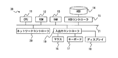
- FIG. 2 is a hardware configuration diagram of a computer forming the demand control device according to Embodiment 1.
- FIG. It is a figure which shows an example of a data structure of the air-conditioning equipment information memorize
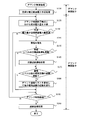
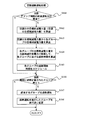
- FIG. 3 is a flowchart showing a demand control process in the first embodiment. 4 is a flowchart showing an air conditioning estimated reduction power prediction process in the first embodiment. 3 is a flowchart showing an air conditioning cutoff operation process in the first embodiment.
- FIG. 8 is a diagram illustrating electric power obtained by estimating the frequency of the outdoor unit using the approximate model in FIG. 7 when the cutoff operation is executed in the first half of the demand time period in the first embodiment.
- 6 is a flowchart showing an air conditioning cutoff operation process in a second embodiment.
- FIG. 1 is a diagram showing an overall configuration and a block configuration of a building management system having an embodiment of a demand control device according to the present invention.
- FIG. 1 shows a configuration in which an environment information measuring unit 3, a demand control device 30, an air conditioning controller 4, a power consumption measuring unit 5, a lighting controller 8, and other electrical equipment 9 are connected to the network 1.
- the devices 3 to 5, 8, 9, and 30 exchange information such as data, control, and instructions via the network 1.
- the environment information measuring unit 3 is a means for acquiring information representing the environment surrounding the building to be managed by measurement, and is realized by various sensors.
- the present embodiment is a technology suitable for air conditioning equipment among electrical equipment to be demand managed, but as environmental information related to air conditioning, in particular, as information that causes fluctuations in the heat load related to air conditioning equipment, the environmental information measuring unit 3 Collects, for example, the outside temperature, the amount of solar radiation, and the like.
- the demand control device 30 is a main control device that is included in a building management server that manages the entire building management system, and that is used to perform demand management based on the measured value by the connected watt-hour meter 2. It is an apparatus which performs air conditioning control characteristic in form.
- the demand control device 30 may be configured as a separate device without being included in the building management server.
- the air conditioning controller 4 is a controller that performs operation control of the connected air conditioning equipment under the control of the demand control device 30.
- Two outdoor units 6 are connected to the air conditioning controller 4 in the present embodiment.
- the used power measuring unit 5 is provided as a used power measuring unit, and is realized by a wattmeter that measures the used power in the attached outdoor unit 6. In the present embodiment, it is assumed that the power usage measuring unit 5 is attached only to the outdoor unit A.
- the lighting controller 8 controls the lighting 81 installed in the building.
- the other electrical equipment 9 is equipment that consumes electricity other than air conditioning equipment and lighting equipment.
- Each of the plurality of indoor units 7 installed in the living space in the building is connected to the outdoor unit 6.
- groups of indoor units may be assigned to areas where the change in room temperature varies depending on, for example, the amount of solar radiation on the north and south sides of the same floor or the outside air temperature.
- the indoor unit 7 in the present embodiment is included in one of two areas (hereinafter referred to as “zones”) A and B as shown in FIG. They are classified into groups A1, A2 and groups B1, B2.
- a group is a unit for performing intermittent interruption operation. In this embodiment, a case where intermittent interruption operation control is performed as an example of low power operation will be described as an example.
- the intermittent cut-off operation is synonymous with the cut-off operation in the present embodiment, and means that the indoor unit 7 (group thereof) is operated at a low load (low power) by an operation such as stopping or blowing.
- the low load (low power) operation is not limited to the operation in which the outdoor unit 6 is completely stopped, and includes a case where the operation is performed with lower power than usual by thermo-off or temperature change.
- the number of outdoor units 6 connected to the air conditioning controller 4 the number of indoor units 7 connected to each outdoor unit 6, the number of zones and the groups included in the zones, groups, and groups
- the number of indoor units 7 included in each is an example, and it is not necessary to limit to this number.
- FIG. 2 is a hardware configuration diagram of a computer forming the demand control device 30 in the present embodiment.
- the computer forming the demand control device 30 in the present embodiment can be realized by a general-purpose hardware configuration that has existed in the past. That is, the computer is provided as a CPU 11, ROM 12, RAM 13, HDD controller 15 connected to a hard disk drive (HDD) 14, a mouse 16 and keyboard 17 provided as input means, and a display device as shown in FIG.
- An input / output controller 19 for connecting each display 18 and a network controller 20 provided as a communication means are connected to an internal bus 21.
- the air conditioning controller 4 may not have a configuration of a mouse or the like connected to the input / output controller 19, but has a configuration similar to that shown in FIG.
- the demand control device 30 in the present embodiment includes an environment information collection unit 31, a power data collection unit 32, a frequency data collection unit 33, a power consumption prediction unit 34, an information transmission unit 35, and a demand control management unit. 36, an air conditioning equipment information storage unit 37, a frequency characteristic information storage unit 38, a performance information storage unit 39, and a demand cutoff list 40.
- the function previously mounted as the demand control apparatus 30 is implement
- the environmental information collection unit 31 is provided as an acquisition unit, and collects environmental information measured by the environmental information measurement unit 3 via the network 1.
- the power data collecting unit 32 collects the used power measured by the used power measuring unit 5 via the network 1.
- the outdoor unit 6 is a heat pump type air conditioner that rotates and cools the compressor (compressor). At this time, the outdoor unit 6 records the operating frequency of the compressor.
- the frequency data collection unit 33 collects the operation frequency data of the outdoor unit 6 via the air conditioning controller 4 and the network 1.
- the power consumption prediction unit 34 is provided as a prediction means, inputs a measurement value by the watt hour meter 2, and determines the demand time limit from the actual power consumption from the start of the demand time limit to the present time within the demand time limit. Predict the amount of power used at the end.
- the calculation method of the predicted power consumption may be the same as before.
- the power consumption prediction unit 34 basically predicts the power consumption based on the correlation between the operating frequency of the outdoor unit and the power. For example, a catalog value may be used as data indicating the correlation between the operating frequency and the power.
- the information transmission unit 35 notifies the building management server of the situation related to demand control in the demand control device 30, such as when it is difficult to use power below the target demand power by only low power operation of the air conditioning equipment.
- the demand control management unit 36 includes a reducible power amount estimation unit 361 and a reduced power amount determination unit 362, and performs demand control by performing overall control such as air conditioning control while performing operation control of the other components 31 to 35. I do.
- the demand control management part 36 in this Embodiment is provided as an air-conditioning control means, and performs intermittent interruption
- the reducible power amount estimation unit 361 is provided as an estimation unit, and is reduced when each group is individually operated for a predetermined interruption unit time within a predetermined measurement period from the start time of the demand time period. The power obtained from the amount of power is estimated as the power that can be reduced by the group.
- the reduced power amount determining unit 362 is provided as a calculation unit, and does not exceed the target demand power amount when the used power amount predicted by the used power amount prediction unit 34 exceeds the target demand power amount preset in the demand time limit.
- the amount of power to be reduced is calculated as a target reduction power amount, and the target reduction power amount is distributed to each group according to a preset distribution standard, and the distribution is performed for each group based on the reducible power amount.
- the cut-off time for reducing the target power reduction amount for each group is calculated. In the present embodiment, a case will be described as an example where target reduction power is equally distributed to each group as a preset distribution criterion.
- the frequency characteristic information storage unit 38 is used when the power consumption of the group is estimated from the operation frequency of the outdoor unit 6 connected to the indoor unit 7 belonging to the group when any group is in the cut-off operation. Frequency characteristic information is stored.
- the frequency characteristic information may be set in advance by a catalog value or the like, or may be set by learning from an actual value. As an example of learning and setting, for example, a model (FIG. 7) generated by correcting a catalog value based on the relationship between the power measured by the outdoor unit A and the operating frequency may be used (the outdoor unit A and the outdoor unit). It can be used if the machine B is the same model).
- the frequency characteristic information will be described together with the description of the operation.
- the track record information storage unit 39 stores track record information related to power usage. Specifically, environmental information such as the date and time when power is used, the power used (kW) of each outdoor unit 6 at that date and time, the ambient temperature, and the amount of solar radiation is accumulated.
- FIG. 3 is a diagram illustrating an example of a data configuration of air conditioning equipment information stored in the air conditioning equipment information storage unit 37 in the present embodiment.
- the air conditioning equipment information in addition to the correspondence relationship between zones, outdoor units 6, groups, and indoor units 7 in the air conditioning equipment, whether or not a power meter (used power measuring unit 5) is attached to the outdoor unit 6 is set. And “reducible power amount” for storing the reducible power amount estimated by the reducible power amount estimation unit 361.
- each item value is set based on the device configuration shown in FIG.
- the demand cut-off list 40 includes equipment information related to equipment other than air conditioning.
- the data configuration depends on the characteristics of the equipment, but includes the zone in which each equipment is installed, the group to which the equipment belongs, the amount of power that can be reduced, the cutoff priority, and the like.
- Each component 31 to 36 in the demand control device 30 is realized by a cooperative operation of a computer forming the demand control device 30 and a program operating on the CPU 11 mounted on the computer.
- the storage units 37 to 40 are realized by the HDD 14 mounted on the demand control device 30.
- the RAM 13 or an external storage means may be used via the network 1.
- the program used in this embodiment can be provided not only by communication means but also by storing it in a computer-readable recording medium such as a CD-ROM or DVD-ROM.
- the program provided from the communication means or the recording medium is installed in the computer, and various processes are realized by the CPU of the computer sequentially executing the program.
- the demand control process in the present embodiment will be described using the flowcharts shown in FIGS. 4A to 4C.
- the case where the demand time limit is 30 minutes will be described as an example, but the demand time limit is not limited to 30 minutes.
- the amount of used power that does not exceed the maximum demand power (demand value) in the demand time period is the target demand power amount.
- the target demand power is a power value calculated by dividing the target demand power amount by the demand time limit.
- step 110 In the air-conditioning control process included in the demand control process in the present embodiment, in order to perform air-conditioning control so as not to exceed the target power demand in each demand time period, air-conditioning estimation that estimates the power that can be reduced in the air-conditioning equipment A reduced power prediction process is performed (step 110). This process will be described with reference to FIGS. 4B and 5.
- a predetermined shut-off unit time for each group within a predetermined measurement period from the start time of the demand time period
- the operation is cut off (low power operation), and the amount of power reduced at that time is recorded as the amount of power that can be reduced in the group.
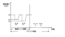
- FIG. 5 shows the power used by the groups A1 and A2 during the demand time period.
- the power consumption amount prediction unit 34 operates constantly, and periodically predicts the power consumption amount at the end of the demand time period from the increased power consumption amount of minute time within the demand time period.
- the demand control management unit 36 performs operation control so that an alarm unit (not shown) outputs an alarm when the used power amount predicted by the used power amount prediction unit 34 exceeds the target demand power amount. However, at the beginning of the demand time period, the alarm operation is controlled so as to suppress the alarm.
- the alarm lock period in FIG. 5 is a period during which the alarm is suppressed. In the present embodiment, the predetermined measurement period described above is associated with this alarm lock period.
- the predetermined measurement period is set to the first 15 minutes of the demand time limit. Of course, it is not necessary to limit to 15 minutes, and it may be appropriately increased or decreased depending on the number of groups. Further, the predetermined measurement period may be set separately from the alarm lock period. In this embodiment, in the alarm lock period set in the first half of the demand time period, the following air-conditioning estimated reduction power prediction process is performed.
- the demand control management unit 36 first determines whether or not an execution condition for the prediction process is satisfied.
- an execution condition of the prediction process for example, a case where the demand time period is set in a time zone that does not clearly exceed the target demand power amount or the like. Note that it is not necessary to execute this process even in the latter half of the demand period.
- the demand control management unit 36 ends this process.
- the demand control management unit 36 refers to the block target group list in which the block target group is set, and is set as a block operation target. Is identified (step 112).
- the groups A1, A2, B1, and B2 shown in FIG. 1 are specified.
- step 112 may be a process of specifying a group that is a target of the estimation process of the reducible power amount in step 115.
- the reducible power amount for the group not specified as the target of the reducible power amount estimation process in step 112 is recorded, for example, in the log file as a result of the reducible power amount estimation process performed in the past.
- the reducible power amount of the group (for example, recent processing result) may be read from the log file, set as an initial value, and recorded in the air conditioning equipment information storage unit 37.
- the demand control management unit 36 instructs the air conditioning controller 4 to perform the cutoff operation for the group for the minimum cutoff time ( ⁇ T).
- the air conditioning controller 4 shuts down the indoor units 7 belonging to the instructed group, and then returns them (step 114).
- the minimum cut-off time ( ⁇ T) is the minimum time required for the indoor unit 7 to be temporarily stopped and then returned.
- the shut-off operation means that the indoor unit 7 (group) is operated at a low load (low power) by an operation such as stopping or blowing as described above.
- the low load (low power) operation is not limited to the operation in which the indoor unit 7 is completely stopped, and includes a case where the operation is performed with lower power than usual by thermo-off or temperature change.
- the power consumption when the indoor units A11 and A12 belonging to the group A1 are stopped is reduced to p1. It shows that. Since the power data collecting unit 32 sequentially collects the used power measured by the used power measuring unit 5 attached to the outdoor unit A, the reducible power amount estimating unit 361 is collected by the power data collecting unit 32. By receiving the used power, it is recognized that the used power is reduced from p0 to p1 when the indoor units A11 and A12 belonging to the group A1 are stopped.
- the reducible power amount estimation unit 361 multiplies the reducible power (p0 ⁇ p1) by the minimum cut-off time ( ⁇ T) to reduce the power amount when the group A1 is cut off (p0 ⁇ p1) ⁇ ⁇ T.
- the amount of power obtained by such calculation is estimated by assuming that the amount of power that can be reduced in group A1, and is written and recorded in the air conditioning equipment information storage unit 37 (step 115).
- the power used during normal operation is fixedly shown as p0, but strictly speaking, it is considered that a slight increase or decrease has occurred. Therefore, it is good also considering the average value of the used electric power immediately before or immediately after when the said group is made to carry out the cutoff operation, or the used electric power immediately before and after as p0.
- the power used at the start of the demand time period may be p0, or the average value of power used when the shut-off operation is not performed within the alarm lock period may be p0.
- Demand control management unit 36 estimates the reducible power amount of the group specified in step 112 if there is a group that has not estimated the reducible power amount (N in step 116). In this example, the reducible power amount of the group A2 is estimated. After the indoor units A11 and A12 belonging to the group A1 return to the normal operation, the demand control management unit 36 performs the shut-off operation by stopping the indoor units A21 and A22 belonging to the group A2 in the same manner as described above, and then Return (step 114). Then, the reducible power amount estimation unit 361 receives the used power collected by the power data collection unit 32 and recognizes that the used power has been reduced from p0 to p2 when the group A2 is cut off. The amount of power that can be reduced in group A2 is estimated as (p0 ⁇ p2) ⁇ ⁇ T (step 115).
- the reducible power amount of the group is obtained for each of the groups A1 and A2.
- the difference between p1 and p2 may be caused not only by the performance of the air conditioning equipment but also by the number of people in the room.
- the reducible power amount of each group is obtained for each of the groups B1 and B2.
- the power consumption measuring unit 5 is not attached to the outdoor unit B. Therefore, when the power consumption measuring unit 5 is not attached, the reducible power amount of each group is obtained as follows.
- the air conditioning controller 4 causes the indoor units 7 belonging to the group B1 instructed in the same way as described above to perform the shut-off operation according to the instruction from the demand control management unit 36 (step 114).
- the air conditioning controller 4 always collects the operating frequency of each outdoor unit 6.
- FIG. 6 shows the collected transition of the operating frequency of the outdoor unit B in the demand time period.
- the operating frequency when the indoor units B11 and B12 belonging to the group B1 are stopped is It shows that it decreased with f1.
- the reducible power amount estimation unit 361 receives the operation frequency collected by the frequency data collection unit 33, so that the group It is recognized that the frequency has decreased from f0 to f1 when the indoor units B11 and B12 belonging to B1 are stopped.
- a relationship of a first order approximation model is generally established between the operating frequency of the inverter type outdoor unit 6 and the electric power used. Therefore, by referring to the correlation model between the operating frequency and the used power, it is possible to convert the operating frequency data shown in FIG. 6 into the used power.
- the frequency characteristic information indicating the relationship between the operation frequency and the power used shown in FIG. 7 is prepared for each outdoor unit 6 and registered in advance in the frequency characteristic information storage unit 38.
- the frequency characteristic information may be generated from past performance information, or may be generated using a catalog value of the outdoor unit 6.
- a plurality of graphs corresponding to the heat load for example, the outside air temperature may be prepared for each outdoor unit 6.
- the reducible power amount estimation unit 361 converts the operating frequency data collected by the frequency data collection unit 33 into power consumption by referring to the frequency characteristics registered in the frequency characteristic information storage unit 38. As a result, the transition of power consumption within the demand time period can be obtained.
- the power consumption thus obtained is shown in FIG. FIG. 8 is a diagram corresponding to FIG. 5 obtained from the used power measured by the used power measuring unit 5, and shows the used power of the groups B1 and B2.
- the groups B1 and B2 corresponding to the outdoor unit B to which the used power measuring unit 5 is not attached the same as the groups A1 and A2 corresponding to the outdoor unit A to which the used power measuring unit 5 is attached.
- the reducible power amount of each group B1, B2 can be estimated (step 115).
- the reducible power amount can be calculated based on the used power obtained by the measurement by the used power measuring unit 5. Even if the measuring unit 5 is not attached, the amount of power that can be reduced can be estimated based on the operating frequency of the outdoor unit 6.
- the demand control management part 36 performs the estimation of the electric energy which can be reduced demonstrated above for every group, the interruption
- the power consumption prediction unit 34 that constantly predicts the power consumption at the end of the demand time period predicts the power consumption even when the first half of the demand time period ends (step 120). 36 confirms whether or not the used power amount predicted by the used power amount prediction unit 34 exceeds the target demand power amount even after the first half of the demand time period has elapsed and the alarm lock release period has started. If it is predicted that the target power demand will not be exceeded (N in Step 130), the demand control management unit 36 may continue to operate the air conditioning equipment as it is.
- the control management unit 36 generates an alarm by alarm means (not shown) (step 140). Then, when the alarm level specified from the amount of power exceeding the target power demand is a level that activates the air conditioning cutoff operation (Y in step 150), the air conditioning cutoff operation processing is performed (step 160). This air conditioning cutoff operation process will be described with reference to FIG. 4C.
- the reduced power amount determination unit 362 calculates a target reduced power amount for air conditioning (target reduced power amount for air conditioning) (Step 162).
- target reduced power amount for air conditioning The amount of power that is used when the predicted power consumption exceeds the target demand power amount at the end of the demand period is the target value of the reduced power amount. Set according to predetermined rules. Subsequently, the reduced power amount determination unit 362 calculates the target reduced power amount of each group from the air conditioning target reduced power amount (step 163).
- the target reduction power amount of each group is calculated by dividing the air conditioning target reduction power amount by the number of groups, but the calculation method is not necessarily limited to this. Subsequently, the reduced power amount determining unit 362 divides the target reduced power amount of each group by the estimated reduced power of the group, and calculates a cutoff time in each group (step 164).
- the air conditioning target reduction power amount is P [kWh]
- (p0-p1) and (p0-p2) are the reducible powers of the groups A1 and A2 that have already been quantified in step 110, respectively, and t1 and t2 are as shown in FIG. This is the blocking time of each group A1, A2.
- n is the number of groups, and in this example, it is 4 of groups A1, A2, B1, and B2.
- the demand control management unit 36 schedules the cut-off operation by determining the cut-off time and the cut-off time for the cut-off operation for each group (step 165).
- the demand control management unit 36 instructs the air conditioning controller 4 to shut off each group according to the schedule until the demand time period ends in the latter half of the demand time period.
- the operation is interrupted for a time (Y, 167 in step 166). Note that if the shut-off operation is not scheduled (N in Step 166), it is not necessary to perform the shut-off operation.
- the groups are sequentially cut off so as not to overlap each other. However, if it is not possible to schedule the shut-off operation so as not to overlap, the overlap is allowed. Then, the demand control management unit 36 performs execution management by changing the state of the group that executed the shut-off operation to “executed” (step 168).
- the cut-off time calculated for each group as described above, and by causing each group to operate in low power by cut-off operation in order, the power consumption in the demand time period does not exceed the target power demand Air conditioning control is performed.
- the demand control management unit 36 refers to the demand shut-off list 40 and applies the other electrical equipment that corresponds. Is blocked (step 180).
- step 190 The above processing is repeatedly executed until the demand time limit elapses (N in step 190).
- the demand control management unit 36 performs a return process so as to return the blocked equipment to the original state (step 200).
- the group with small power consumption in the above example, group A2
- group A2 has a low thermal load
- running is performed so that it may not exceed target power demand amount while minimizing deterioration of living space environment by suppressing the fall of the comfort of living space.
- the target reduction power amount is allocated with reference to the external environment such as the outside air temperature in the demand time limit, so the accuracy of the operation control of the air conditioning equipment so as not to exceed the target demand power amount Can be improved.
- the air conditioning control was performed so that the target power demand was not exceeded by shut-off operation in the second half of the demand time period, but then the power was used more than expected, and the predicted power consumption exceeded the target power demand again. There may be cases. In such a case, the used power amount exceeding the target demand power amount may be redistributed to each group to be cut off. It should be noted that whether or not the target power demand amount is exceeded may be checked once in a few minutes before the end point, not periodically in the second half of the demand time period.
- the target reduction power amount is evenly distributed to the group according to the preset distribution standard, but it is not always necessary to distribute the target evenly by adopting different distribution standards.
- a distribution ratio may be set according to the importance of rooms (groups) such as a living room and a reception room. In the case of a reception room, it will be allocated so that the cut-off time will be much shorter than rooms with relatively low importance, etc., or the cut-off time for groups with relatively many claims will be shorter than for groups with few claims. Or may be distributed.
- the group that is not specified as the target of the cutoff operation in Step 112 in FIG. 4B may be included in the target of the cutoff operation.
- the estimation process (step 115) of the reducible electric energy is not performed for the group that is not the target of the shut-off operation, the group can be reduced when it is included in the target of the shut-off operation.
- Power estimation process may be performed, or as described above, the result of estimation process of the reducible power quantity implemented in the past is recorded in the log file, and the estimated reduction for the group in the past.
- the possible power amount (for example, recent processing result) may be used as the reducible power amount of the group.
- the electric equipment other than the air conditioning equipment for example, the lighting equipment is operated at low power, and the reduction power amount values of the air conditioning equipment and the lighting equipment are combined so that the maximum demand power is not exceeded. May be performed.
- the intermittent interruption operation in which the indoor unit 7 (group) is operated with low load (low power) by operation such as stopping or blowing is described as an example.
- the intermittent interruption operation in which the indoor unit 7 (group) is operated with low load (low power) by operation such as stopping or blowing is described as an example.
- another operation method such as completely stopping the operation of the air conditioning equipment, it may be adopted.
- Embodiment 2 As shown in FIG. 1, the indoor units A11 and A12 are grouped into a group A1, the indoor units A21 and A22 are grouped into a group A2, and the groups A1 and A2 are assigned to the zone A. Furthermore, the indoor units B11 and B12 are grouped into a group B1, the indoor units B21 and B22 are grouped into a group B2, and the groups B1 and B2 are assigned to the zone B. In this way, when the indoor units 7 are grouped into a plurality of groups based on the installation location and each group is assigned to one of a plurality of areas, in the present embodiment, each group is considered in consideration of the area (zone). It is characterized by calculating the shut-off time.
- the configuration of the present embodiment may be the same as that of the first embodiment, and when calculating the blocking time of each group in the demand control process, the processing in the present embodiment is the same as that of the first embodiment and FIG. 4C. Since only the air conditioning cutoff operation process shown is different, the air conditioning cutoff operation process will be described with reference to FIG. Note that the same step numbers are assigned to the same processes as those in FIG. 4C used in Embodiment 1, and description thereof is omitted as appropriate.
- the reduced power amount determination unit 362 calculates a target reduced power amount for air conditioning (target reduced power amount for air conditioning) (Step 162).
- target reduced power amount for air conditioning The amount of power that is used when the predicted power consumption exceeds the target demand power amount at the end of the demand period is the target value of the reduced power amount. Set according to predetermined rules. Subsequently, the reduced power amount determination unit 362 distributes the air-conditioning target reduced power amount equally to each zone (step 1611).
- this allocated power reduction amount (hereinafter referred to as “target value for each zone”) is further distributed to each group in each zone so as to achieve the target.
- the reduced power amount determination unit 362 in the present embodiment obtains and schedules the cut-off time of each group by equally distributing the target value for each zone to each group.
- Q (p0 ⁇ p1) ⁇ t1 + (p0 ⁇ p2) ⁇ t2
- (p0-p1) and (p0-p2) are the reducible powers of the groups A1 and A2 that have already been quantified in step 110, respectively, and t1 and t2 are as shown in FIG. This is the blocking time of each group A1, A2.
- n the number of groups included in the zone.
- the reduced power amount determination unit 362 in the present embodiment equally distributes the air-conditioning target reduced power amount to each zone in this way, and the distributed reduced power amount (target value for each zone) is included in the zone. For each group, the cutoff time is calculated based on the reducible power of the group.
- the air conditioning target reduction power amount is evenly distributed to each zone, but it is not always necessary to distribute it equally.
- the air conditioning target reduction power amount may be distributed more to the larger number of units according to the ratio of the number of indoor units 7 connected to the outdoor unit 6.
- you may consider a heat load For example, in consideration of the amount of solar radiation and the outside air temperature, it can be estimated that the heat load applied to the air conditioner installed in the zone on the south side of the building is larger than the heat load applied to the air conditioner installed in the zone on the north side of the building. Therefore, the air conditioning target reduction power amount is allocated so that the reduction power amount allocated to the zone having a relatively high heat load is reduced.
- the reduced power amount determining unit 362 when the environmental information collecting unit 31 collects the environmental information measured by the environmental information measuring unit 3 at the present time, the reduced power amount determining unit 362, for example, generates power in each zone when the outside air temperature is 30 degrees. Referring to the performance information, the target reduction power amount for air conditioning is allocated so that the amount of power allocated to the high power consumption zone is reduced according to the power consumption ratio. Also good.
Landscapes
- Engineering & Computer Science (AREA)
- General Engineering & Computer Science (AREA)
- Chemical & Material Sciences (AREA)
- Combustion & Propulsion (AREA)
- Mechanical Engineering (AREA)
- Physics & Mathematics (AREA)
- Signal Processing (AREA)
- Power Engineering (AREA)
- Fuzzy Systems (AREA)
- Mathematical Physics (AREA)
- General Physics & Mathematics (AREA)
- Automation & Control Theory (AREA)
- Human Computer Interaction (AREA)
- Health & Medical Sciences (AREA)
- Medical Informatics (AREA)
- Software Systems (AREA)
- Evolutionary Computation (AREA)
- Computer Vision & Pattern Recognition (AREA)
- Artificial Intelligence (AREA)
- Air Conditioning Control Device (AREA)
- Supply And Distribution Of Alternating Current (AREA)
Abstract
La présente invention concerne une régulation de conditionnement d'air comportant un fonctionnement à faible puissance de manière à ne pas dépasser une quantité de puissance de la demande cible à l'intérieur d'une période de mesure prédéfinie tout en empêchant le confort d'un espace de vie d'être détérioré. Un dispositif de régulation de la demande possède : une unité (361) d'estimation de la quantité de puissance réductible destinée à permettre à des unités d'intérieur (7) d'effectuer une opération d'interruption sur une base par groupe, pour le temps d'interruption minimum, pendant la première moitié d'une période de demande, ce qui permet d'obtenir des quantités de puissance réductible sur une base par groupe ; et une unité (362) de détermination de la quantité de puissance de réduction destinée à, après que la première moitié de la période de demande s'est écoulée, lorsqu'une quantité de puissance utilisée prédite par une unité (34) de prédiction de la quantité de puissance utilisée dépasse la quantité de puissance de la demande cible, attribuer la quantité excédentaire de puissance à chaque zone, attribuer de façon égale la quantité de puissance attribuée à chaque groupe dans chaque zone et calculer le temps d'interruption de chaque groupe à établir lorsqu'il est permis à chaque groupe d'effectuer une opération d'interruption afin de réduire la quantité de puissance attribuée sur la base de la quantité de puissance réductible de chaque groupe.
Priority Applications (3)
| Application Number | Priority Date | Filing Date | Title |
|---|---|---|---|
| US15/116,681 US10180672B2 (en) | 2014-02-14 | 2014-11-20 | Demand control device and computer readable medium |
| CN201480074371.2A CN105940584B (zh) | 2014-02-14 | 2014-11-20 | 需求控制装置 |
| EP14882313.1A EP3107173B1 (fr) | 2014-02-14 | 2014-11-20 | Programme et dispositif de régulation de demande |
Applications Claiming Priority (2)
| Application Number | Priority Date | Filing Date | Title |
|---|---|---|---|
| JP2014-026064 | 2014-02-14 | ||
| JP2014026064A JP6067602B2 (ja) | 2014-02-14 | 2014-02-14 | デマンド制御装置及びプログラム |
Publications (1)
| Publication Number | Publication Date |
|---|---|
| WO2015122074A1 true WO2015122074A1 (fr) | 2015-08-20 |
Family
ID=53799829
Family Applications (1)
| Application Number | Title | Priority Date | Filing Date |
|---|---|---|---|
| PCT/JP2014/080709 WO2015122074A1 (fr) | 2014-02-14 | 2014-11-20 | Programme et dispositif de régulation de demande |
Country Status (5)
| Country | Link |
|---|---|
| US (1) | US10180672B2 (fr) |
| EP (1) | EP3107173B1 (fr) |
| JP (1) | JP6067602B2 (fr) |
| CN (1) | CN105940584B (fr) |
| WO (1) | WO2015122074A1 (fr) |
Cited By (3)
| Publication number | Priority date | Publication date | Assignee | Title |
|---|---|---|---|---|
| WO2020003684A1 (fr) * | 2018-06-28 | 2020-01-02 | 三菱電機株式会社 | Programme et dispositif de régulation de demande |
| JPWO2021220353A1 (fr) * | 2020-04-27 | 2021-11-04 | ||
| CN114034106A (zh) * | 2021-11-10 | 2022-02-11 | 珠海格力电器股份有限公司 | 多联机组控制方法、装置和多联机组设备 |
Families Citing this family (17)
| Publication number | Priority date | Publication date | Assignee | Title |
|---|---|---|---|---|
| US9026242B2 (en) | 2011-05-19 | 2015-05-05 | Taktia Llc | Automatically guided tools |
| EP3964902B1 (fr) | 2012-04-26 | 2024-01-03 | Shaper Tools, Inc. | Systèmes et procédés permettant de réaliser une tâche sur un matériau, ou permettant de localiser la position d'un dispositif par rapport à la surface du matériau |
| US10456883B2 (en) | 2015-05-13 | 2019-10-29 | Shaper Tools, Inc. | Systems, methods and apparatus for guided tools |
| JP6482504B2 (ja) * | 2016-07-22 | 2019-03-13 | 三菱電機ビルテクノサービス株式会社 | 電力制御装置及びプログラム |
| CN114879598A (zh) | 2016-08-19 | 2022-08-09 | 整形工具股份有限公司 | 用于共享工具制造和设计数据的系统、方法和装置 |
| KR101984923B1 (ko) * | 2017-09-12 | 2019-05-31 | 엘지전자 주식회사 | 공기조화기 |
| DE102018110044B4 (de) * | 2018-04-26 | 2024-01-25 | Sma Solar Technology Ag | Verfahren und Vorrichtung zum aufeinander abgestimmten Betreiben von elektrischen Einrichtungen |
| US11349337B2 (en) * | 2018-06-27 | 2022-05-31 | Mitsubishi Electric Corporation | Energy setting device, energy setting method, and recording medium |
| JP7027273B2 (ja) * | 2018-07-11 | 2022-03-01 | 三菱電機ビルテクノサービス株式会社 | 設備選択支援装置及びプログラム |
| JP6591126B1 (ja) * | 2018-08-08 | 2019-10-16 | 三菱電機ビルテクノサービス株式会社 | 節電支援システム、遠隔管理装置及び節電支援プログラム |
| JP6949790B2 (ja) * | 2018-08-23 | 2021-10-13 | 三菱電機ビルテクノサービス株式会社 | 電力管理装置 |
| KR20200068870A (ko) * | 2018-12-06 | 2020-06-16 | 삼성전자주식회사 | 에너지 절감을 제어하는 방법 및 그 장치 |
| CN110686382B (zh) * | 2019-10-16 | 2021-02-09 | 广东美的暖通设备有限公司 | 空调控制方法、装置及计算机可读存储介质 |
| CN111695817B (zh) * | 2020-06-15 | 2023-12-01 | 阳光新能源开发股份有限公司 | 一种需量削减量的计算方法、装置及系统 |
| CN111830350B (zh) * | 2020-07-23 | 2022-02-11 | 珠海格力电器股份有限公司 | 能耗计量方法、装置及电器 |
| JP7093034B2 (ja) * | 2020-09-30 | 2022-06-29 | ダイキン工業株式会社 | 電力制御システムおよびプログラム |
| JPWO2022153534A1 (fr) * | 2021-01-18 | 2022-07-21 |
Citations (1)
| Publication number | Priority date | Publication date | Assignee | Title |
|---|---|---|---|---|
| JP2014003727A (ja) * | 2012-06-15 | 2014-01-09 | Mitsubishi Electric Building Techno Service Co Ltd | 電力制御システム及び電力監視装置 |
Family Cites Families (8)
| Publication number | Priority date | Publication date | Assignee | Title |
|---|---|---|---|---|
| EP0003010A1 (fr) * | 1977-12-27 | 1979-07-11 | United Technologies Corporation | Procédé et appareil pour limiter la consommation d'énergie en chauffage, ventilation et conditionnement d'air |
| JP4552119B2 (ja) * | 2004-07-16 | 2010-09-29 | 清水建設株式会社 | マルチエアコンのデマンド制御システム |
| KR20080066489A (ko) | 2007-01-12 | 2008-07-16 | 삼성전자주식회사 | 시스템 에어컨의 실내기 그룹설정장치 및 그 방법 |
| KR100844324B1 (ko) * | 2007-01-26 | 2008-07-07 | 엘지전자 주식회사 | 멀티에어컨의 디맨드 제어시스템 및 디맨드 제어방법 |
| KR100844326B1 (ko) * | 2007-01-26 | 2008-07-07 | 엘지전자 주식회사 | 멀티에어컨의 디맨드 제어시스템 및 디맨드 제어방법 |
| JP4548455B2 (ja) * | 2007-07-13 | 2010-09-22 | ダイキン工業株式会社 | デマンド制御装置、デマンド制御方法およびデマンド制御プログラム |
| KR101801095B1 (ko) * | 2010-10-25 | 2017-11-24 | 삼성전자주식회사 | 전력 관리 장치, 그를 가지는 전력 관리 시스템 및 그 제어 방법 |
| EP2858196B1 (fr) * | 2012-05-31 | 2021-09-29 | Nihon Techno Co., Ltd. | Système, procédé et programme d'économie d'énergie |
-
2014
- 2014-02-14 JP JP2014026064A patent/JP6067602B2/ja active Active
- 2014-11-20 WO PCT/JP2014/080709 patent/WO2015122074A1/fr active Application Filing
- 2014-11-20 CN CN201480074371.2A patent/CN105940584B/zh active Active
- 2014-11-20 EP EP14882313.1A patent/EP3107173B1/fr active Active
- 2014-11-20 US US15/116,681 patent/US10180672B2/en active Active
Patent Citations (1)
| Publication number | Priority date | Publication date | Assignee | Title |
|---|---|---|---|---|
| JP2014003727A (ja) * | 2012-06-15 | 2014-01-09 | Mitsubishi Electric Building Techno Service Co Ltd | 電力制御システム及び電力監視装置 |
Cited By (6)
| Publication number | Priority date | Publication date | Assignee | Title |
|---|---|---|---|---|
| WO2020003684A1 (fr) * | 2018-06-28 | 2020-01-02 | 三菱電機株式会社 | Programme et dispositif de régulation de demande |
| JPWO2021220353A1 (fr) * | 2020-04-27 | 2021-11-04 | ||
| WO2021220353A1 (fr) * | 2020-04-27 | 2021-11-04 | 三菱電機株式会社 | Système de climatisation et procédé de régulation de la quantité d'énergie dans un système de climatisation |
| JP7305042B2 (ja) | 2020-04-27 | 2023-07-07 | 三菱電機株式会社 | 空調システムおよび空調システムの電力量を制御する方法 |
| CN114034106A (zh) * | 2021-11-10 | 2022-02-11 | 珠海格力电器股份有限公司 | 多联机组控制方法、装置和多联机组设备 |
| CN114034106B (zh) * | 2021-11-10 | 2023-05-12 | 珠海格力电器股份有限公司 | 多联机组控制方法、装置和多联机组设备 |
Also Published As
| Publication number | Publication date |
|---|---|
| EP3107173B1 (fr) | 2021-03-17 |
| EP3107173A4 (fr) | 2017-11-01 |
| JP2015154580A (ja) | 2015-08-24 |
| JP6067602B2 (ja) | 2017-01-25 |
| EP3107173A1 (fr) | 2016-12-21 |
| US20160349725A1 (en) | 2016-12-01 |
| CN105940584B (zh) | 2018-09-28 |
| US10180672B2 (en) | 2019-01-15 |
| CN105940584A (zh) | 2016-09-14 |
Similar Documents
| Publication | Publication Date | Title |
|---|---|---|
| JP6067602B2 (ja) | デマンド制御装置及びプログラム | |
| US8880226B2 (en) | System and method to predict optimized energy consumption | |
| US20170159955A1 (en) | Air-conditioning controller, air-conditioning control method and air-conditioning control program | |
| JP2014236605A (ja) | 空気調和装置の管理システム | |
| US20170198932A1 (en) | Management system and management method | |
| EP2806226B1 (fr) | Dispositif de commande de climatiseur | |
| JP6605181B2 (ja) | 運転制御装置、空気調和システム、運転制御方法および運転制御プログラム | |
| CN103513632A (zh) | 能源管理系统 | |
| JP5826714B2 (ja) | 電力制御システム及び電力監視装置 | |
| JP6063407B2 (ja) | 需要調整計画立案システムおよび需要調整計画立案方法 | |
| JP7215069B2 (ja) | 制御プログラム、制御方法および制御装置 | |
| WO2014115247A1 (fr) | Dispositif de commande de système, système de gestion d'installation, procédé de commande de demande, et programme | |
| JP2020086910A (ja) | 空調システム管理装置、データ提供システム、データ提供方法、及び、プログラム | |
| JP6701761B2 (ja) | 電力消費管理装置、電力消費管理システムおよび電力消費管理プログラム | |
| JP5951270B2 (ja) | 空気調和機の消費電力量管理制御システム、サーバ装置、クライアント装置及び空気調和機の消費電力量管理制御方法 | |
| US20160241033A1 (en) | Control device, control method, and program | |
| JP5818089B2 (ja) | 需要電力制御装置および需要電力制御方法 | |
| JP7215070B2 (ja) | 制御プログラム、制御方法および制御装置 | |
| US20140039715A1 (en) | System-side controller and method | |
| JP2015163010A (ja) | デマンド制御方法及びデマンド制御システム | |
| JP6298346B2 (ja) | 需要調整計画立案システムおよび需要調整計画立案方法 | |
| JP5975276B2 (ja) | 運転管理装置、デマンドレスポンス制御発動時の電力実測値補正方法 | |
| JP2013228121A (ja) | 空調設備の制御装置 | |
| WO2024009354A1 (fr) | Dispositif de commande de quantité d'énergie, procédé de commande de quantité d'énergie et programme | |
| US20220146334A1 (en) | Method for Determining a Thermal Consumption of an Energy System, Energy Management System and Energy System |
Legal Events
| Date | Code | Title | Description |
|---|---|---|---|
| 121 | Ep: the epo has been informed by wipo that ep was designated in this application |
Ref document number: 14882313 Country of ref document: EP Kind code of ref document: A1 |
|
| WWE | Wipo information: entry into national phase |
Ref document number: 15116681 Country of ref document: US |
|
| REEP | Request for entry into the european phase |
Ref document number: 2014882313 Country of ref document: EP |
|
| WWE | Wipo information: entry into national phase |
Ref document number: 2014882313 Country of ref document: EP |
|
| NENP | Non-entry into the national phase |
Ref country code: DE |