WO2015122034A1 - Dispositif amortisseur de vibrations - Google Patents
Dispositif amortisseur de vibrations Download PDFInfo
- Publication number
- WO2015122034A1 WO2015122034A1 PCT/JP2014/069356 JP2014069356W WO2015122034A1 WO 2015122034 A1 WO2015122034 A1 WO 2015122034A1 JP 2014069356 W JP2014069356 W JP 2014069356W WO 2015122034 A1 WO2015122034 A1 WO 2015122034A1
- Authority
- WO
- WIPO (PCT)
- Prior art keywords
- chamber
- liquid
- communication
- wall surface
- cylinder
- Prior art date
Links
Images


Classifications
-
- F—MECHANICAL ENGINEERING; LIGHTING; HEATING; WEAPONS; BLASTING
- F16—ENGINEERING ELEMENTS AND UNITS; GENERAL MEASURES FOR PRODUCING AND MAINTAINING EFFECTIVE FUNCTIONING OF MACHINES OR INSTALLATIONS; THERMAL INSULATION IN GENERAL
- F16F—SPRINGS; SHOCK-ABSORBERS; MEANS FOR DAMPING VIBRATION
- F16F13/00—Units comprising springs of the non-fluid type as well as vibration-dampers, shock-absorbers, or fluid springs
- F16F13/04—Units comprising springs of the non-fluid type as well as vibration-dampers, shock-absorbers, or fluid springs comprising both a plastics spring and a damper, e.g. a friction damper
- F16F13/06—Units comprising springs of the non-fluid type as well as vibration-dampers, shock-absorbers, or fluid springs comprising both a plastics spring and a damper, e.g. a friction damper the damper being a fluid damper, e.g. the plastics spring not forming a part of the wall of the fluid chamber of the damper
- F16F13/08—Units comprising springs of the non-fluid type as well as vibration-dampers, shock-absorbers, or fluid springs comprising both a plastics spring and a damper, e.g. a friction damper the damper being a fluid damper, e.g. the plastics spring not forming a part of the wall of the fluid chamber of the damper the plastics spring forming at least a part of the wall of the fluid chamber of the damper
- F16F13/10—Units comprising springs of the non-fluid type as well as vibration-dampers, shock-absorbers, or fluid springs comprising both a plastics spring and a damper, e.g. a friction damper the damper being a fluid damper, e.g. the plastics spring not forming a part of the wall of the fluid chamber of the damper the plastics spring forming at least a part of the wall of the fluid chamber of the damper the wall being at least in part formed by a flexible membrane or the like
- F16F13/105—Units comprising springs of the non-fluid type as well as vibration-dampers, shock-absorbers, or fluid springs comprising both a plastics spring and a damper, e.g. a friction damper the damper being a fluid damper, e.g. the plastics spring not forming a part of the wall of the fluid chamber of the damper the plastics spring forming at least a part of the wall of the fluid chamber of the damper the wall being at least in part formed by a flexible membrane or the like characterised by features of partitions between two working chambers
- F16F13/107—Passage design between working chambers
-
- B—PERFORMING OPERATIONS; TRANSPORTING
- B60—VEHICLES IN GENERAL
- B60K—ARRANGEMENT OR MOUNTING OF PROPULSION UNITS OR OF TRANSMISSIONS IN VEHICLES; ARRANGEMENT OR MOUNTING OF PLURAL DIVERSE PRIME-MOVERS IN VEHICLES; AUXILIARY DRIVES FOR VEHICLES; INSTRUMENTATION OR DASHBOARDS FOR VEHICLES; ARRANGEMENTS IN CONNECTION WITH COOLING, AIR INTAKE, GAS EXHAUST OR FUEL SUPPLY OF PROPULSION UNITS IN VEHICLES
- B60K5/00—Arrangement or mounting of internal-combustion or jet-propulsion units
- B60K5/12—Arrangement of engine supports
- B60K5/1208—Resilient supports
-
- F—MECHANICAL ENGINEERING; LIGHTING; HEATING; WEAPONS; BLASTING
- F16—ENGINEERING ELEMENTS AND UNITS; GENERAL MEASURES FOR PRODUCING AND MAINTAINING EFFECTIVE FUNCTIONING OF MACHINES OR INSTALLATIONS; THERMAL INSULATION IN GENERAL
- F16F—SPRINGS; SHOCK-ABSORBERS; MEANS FOR DAMPING VIBRATION
- F16F2222/00—Special physical effects, e.g. nature of damping effects
- F16F2222/12—Fluid damping
Definitions
- the present invention relates to a vibration isolator that is applied to, for example, automobiles and industrial machines and absorbs and attenuates vibrations of a vibration generating unit such as an engine.
- the vibration isolator includes a cylindrical first mounting member connected to one of the vibration generating unit and the vibration receiving unit, a second mounting member connected to the other, and an elastic connecting the both mounting members. And a partition member that partitions the liquid chamber in the first mounting member into which the liquid is sealed into a first liquid chamber and a second liquid chamber.
- the vibration isolator further includes a first restriction passage and a second restriction passage communicating the two liquid chambers with each other, a cylinder chamber provided between the two liquid chambers, and an open position and a closed position in the cylinder chamber. And a plunger member arranged to be movable between the two.
- a plurality of types of vibrations having different frequencies, such as idle vibrations and shake vibrations, are input to the vibration isolator. Therefore, in this vibration isolator, the resonance frequency of each of the first restriction passage and the second restriction passage is set (tuned) to a different type of vibration frequency.
- the plunger member moves between the open position and the closed position according to the input vibration frequency, so that the restriction passage through which the liquid flows is changed into the first restriction passage and the second restriction passage. Switching.
- the conventional vibration isolator has room for improvement in terms of suppressing abnormal noise generated when the plunger member moves, simplifying the structure, and facilitating manufacture.
- unintended vibration such as fine vibration having a frequency higher than the resonance frequency of the restriction passage and determined by the restriction passage length or cross-sectional area. If the restriction passage is clogged, the dynamic spring constant increases, which may affect the product characteristics of the vibration isolator, such as the ride comfort of an automobile.
- the present invention has been made in view of the above-described circumstances, and an object thereof is to provide a vibration isolator capable of suppressing the generation of abnormal noise while ensuring product characteristics, simplifying the structure, and facilitating manufacture. To do.
- the vibration isolator according to the present invention includes a cylindrical first attachment member connected to one of the vibration generating portion and the vibration receiving portion, a second attachment member connected to the other, and both of these attachment members.
- An elastic body to be connected; and a partition member that divides a liquid chamber in the first mounting member in which the liquid is sealed into a first liquid chamber and a second liquid chamber, of the first liquid chamber and the second liquid chamber At least one of the vibration isolator having the elastic body in a part of the wall surface, wherein the partition member is provided with a communication chamber for communicating the first liquid chamber and the second liquid chamber, and the partition Of the wall surfaces forming the communication chamber in the member, the first wall surface and the second wall surface facing each other with the communication chamber interposed therebetween are each provided with a communication hole that opens toward the communication chamber, As the communication hole, the communication chamber and the first liquid chamber are provided on the first wall surface.
- the first communication hole and the second communication hole are The first wall and the second wall are arranged so as to be shifted from each other in an orthogonal direction perpendicular to the facing direction in which the first wall surface and the second wall surface face each other, and the first communication hole is formed by the inside of the first protruding cylinder protruding from the first wall surface into the communication chamber. ing.
- the first mounting member and the second mounting member are relatively displaced while elastically deforming the elastic body, so that the liquid is in the first liquid chamber and the second liquid chamber. Circulate through the communication room.
- the flow rate of the liquid increases.
- the liquid that has flowed into the communication chamber from the second communication hole flows in the communication chamber in the opposite direction and reaches the first wall surface, and the flow is changed by the first wall surface.
- the flow of the liquid is changed along the first wall surface in the orthogonal direction, and then reaches the outer peripheral surface of the first projecting cylinder, and the first projecting along the outer peripheral surface of the first projecting cylinder.
- the vibration can be absorbed and attenuated by increasing the pressure loss of the liquid in accordance with the flow velocity of the liquid flowing in the communication chamber.
- the vibration when a normal vibration such as an idle vibration or a shake vibration is input, the vibration can be absorbed and attenuated regardless of the vibration frequency. Accordingly, it is possible to suppress the generation of abnormal noise while absorbing and attenuating a plurality of types of vibrations having different frequencies, thereby simplifying the structure and facilitating manufacture. Moreover, under a state where the flow velocity is low and the pressure loss of the liquid is suppressed, the liquid smoothly passes through the communication chamber, and the increase of the dynamic spring constant is suppressed. For example, when an unintended vibration such as a micro vibration with a frequency higher than that of a normal vibration and an extremely small amplitude is input, when the liquid flow rate is slower than when a normal vibration is input, the dynamic spring constant increases. Can be suppressed, and the product characteristics of the vibration isolator can be easily secured.
- the outer peripheral surface of the first projecting cylinder may be gradually reduced in diameter as it goes from the base end part of the first projecting cylinder to the projecting end part.
- the diameter of the outer peripheral surface of the first projecting cylinder is gradually reduced from the base end portion of the first projecting cylinder toward the projecting end portion. Therefore, when the liquid whose flow rate is increased flows into the communication chamber from the second communication hole, the liquid is directed from the base end portion of the first projecting tube toward the projecting end portion along the outer peripheral surface of the first projecting tube. It is possible to flow smoothly, and the pressure loss of the liquid can be surely increased.
- the second communication hole may be formed by the inside of the second protruding cylinder protruding from the second wall surface into the communication chamber.
- the first communication hole is formed by the inside of the first projecting cylinder and the second communication hole is formed by the inside of the second projecting cylinder, it is between the first liquid chamber and the second liquid chamber.
- the flow rate of liquid flowing through the communication chamber becomes faster. Therefore, it is possible to increase the pressure loss of the liquid both when the liquid goes from the first liquid chamber to the second liquid chamber through the communication chamber and when the liquid goes from the second liquid chamber to the first liquid chamber through the communication chamber. Thus, vibration can be absorbed and damped reliably.
- the vibration isolator of the present invention it is possible to suppress the generation of abnormal noise while ensuring the product characteristics, simplify the structure and facilitate the manufacture.
- the vibration isolator 10 includes a cylindrical first mounting member 11 connected to one of a vibration generating unit and a vibration receiving unit, and a second mounting member connected to the other. 12, an elastic body 13 that couples the two attachment members 11, 12 to each other, a liquid chamber in the first attachment member 11 in which the liquid L is sealed, and a main liquid having the elastic body 13 as a part of the wall surface.
- the second mounting member 12 is formed in a columnar shape
- the elastic body 13 is formed in a cylindrical shape.
- the first mounting member 11, the second mounting member 12, and the elastic body 13 are arranged coaxially with the common shaft.
- this common shaft is referred to as an axis (axis of the first mounting member) O
- the main liquid chamber 14 side along the axis O direction (the axial direction of the communication hole or the opposing direction of the communication hole) is referred to as one side.
- the liquid chamber 15 side is called the other side
- the direction orthogonal to the axis O is called the radial direction
- the direction around the axis O is called the circumferential direction.
- the vibration isolator 10 When the vibration isolator 10 is mounted on, for example, an automobile, the second mounting member 12 is connected to an engine as a vibration generating unit.
- the first mounting member 11 is connected to a vehicle body as a vibration receiving portion via a bracket (not shown), and the vibration of the engine is prevented from being transmitted to the vehicle body.
- the vibration isolator 10 is a liquid enclosure type in which a liquid L such as ethylene glycol, water, or silicone oil is enclosed in the liquid chamber of the first mounting member 11.
- the first attachment member 11 includes a one-side outer cylinder 21 located on one side and an other-side outer cylinder 22 located on the other side along the axis O direction.
- the elastic body 13 is connected to an end portion on one side of the one-side outer cylinder 21 in a liquid-tight state.
- the opening on one side of the one-side outer cylinder 21 is closed by the elastic body 13.
- the other-side end portion 21a is formed to have a larger diameter than other portions.
- the inside of the one side outer cylinder 21 is the main liquid chamber 14.
- the hydraulic pressure in the main liquid chamber 14 varies as the elastic body 13 is deformed and the internal volume of the main liquid chamber 14 changes when vibration is input.
- an annular groove 21 b that extends continuously over the entire circumference is formed in a portion that is continuous from the other side with respect to a portion to which the elastic body 13 is connected.
- a diaphragm 17 is connected to the other end of the other outer cylinder 22 in a liquid-tight state, and the opening on the other side of the other outer cylinder 22 is closed by the diaphragm 17.
- one end 22 a has a larger diameter than the other part, and is fitted in the other-side end 21 a of the one-side outer cylinder 21.
- the partition member 16 is fitted in the other side outer cylindrical body 22, and a portion of the inside of the other side outer cylindrical body 22 located between the partition member 16 and the diaphragm 17 is a sub liquid chamber. It is 15.
- the auxiliary liquid chamber 15 has the diaphragm 17 as a part of the wall surface, and expands and contracts when the diaphragm 17 is deformed.
- the other side outer cylinder body 22 is almost entirely covered with a rubber film formed integrally with the diaphragm 17.
- An internal thread portion 12a is formed coaxially with the axis O on one end face of the second mounting member 12.
- the second mounting member 12 protrudes from the first mounting member 11 to one side.
- the second mounting member 12 is formed with a flange portion 12b that protrudes outward in the radial direction and continuously extends over the entire circumference.
- the flange portion 12 b is separated from one end of the first attachment member 11 to one side.
- the elastic body 13 is formed of, for example, a rubber material that can be elastically deformed, and is formed in a cylindrical shape whose diameter is gradually increased from one side to the other side.
- One end of the elastic body 13 is connected to the second mounting member 12, and the other end is connected to the first mounting member 11. Note that the inner peripheral surface of the one outer cylinder 21 of the first mounting member 11 is covered with a rubber film formed integrally with the elastic body 13 over almost the entire area.
- the partition member 16 includes a pair of end surface portions 16a and 16b and a peripheral wall portion 16c.
- Each of the pair of end surface portions 16a and 16b is formed in a plate shape whose front and back surfaces face the direction of the axis O, and is arranged coaxially with the axis O.
- the first end surface portion 16a located on one side is formed to have a larger diameter than the second end surface portion 16b located on the other side.
- the first end surface portion 16a and the second end surface portion 16b are arranged with a space in the direction of the axis O, and sandwich the peripheral wall portion 16c in the direction of the axis O.
- the peripheral wall portion 16 c is formed in an annular shape that opens in the direction of the axis O, and is arranged coaxially with the axis O.
- the peripheral wall portion 16 c is provided with a protruding portion 16 d that protrudes inward in the radial direction.
- a plurality of protruding portions 16d are arranged at intervals in the circumferential direction, and are sandwiched in the direction of the axis O by the pair of end surface portions 16a and 16b.
- the outer diameter of the peripheral wall portion 16c is equivalent to the outer diameter of the second end surface portion 16b. Further, the peripheral wall portion 16 c and the second end surface portion 16 b are fitted in the first mounting member 11. Of the first end surface portion 16 a, the flange portion 16 e that protrudes outward in the radial direction from the peripheral wall portion 16 c is disposed in the one end portion 22 a of the other side outer cylindrical body 22.
- the partition member 16 is provided with a communication chamber 30 that allows the main liquid chamber 14 and the sub-liquid chamber 15 to communicate with each other.
- the communication chamber 30 is provided between the first end surface portion 16a, the second end surface portion 16b, and the peripheral wall portion 16c.
- the interior of the peripheral wall portion 16c is closed from both sides in the axis O direction by the first end surface portion 16a and the second end surface portion 16b.
- the communication chamber 30 is formed in a flat columnar shape arranged coaxially with the axis O.
- the first wall surface 30 a and the second wall surface 30 b that are opposed to each other with the communication chamber 30 interposed therebetween are provided on the wall surface that forms the communication chamber 30 in the partition member 16.
- the first wall surface 30a and the second wall surface 30b face each other in the direction of the axis O.
- the 1st wall surface 30a is comprised by the wall surface which faces the other side in the 1st end surface part 16a.
- the 2nd wall surface 30b is comprised by the wall surface which faces one side in the 2nd end surface part 16b.
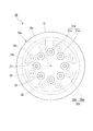
- the first wall surface 30 a and the second wall surface 30 b are provided with communication holes 31 and 32 that open toward the communication chamber 30.
- a first communication hole 31 provided in the first wall surface 30a and a second communication hole 32 provided in the second wall surface 30b are provided.
- the first communication hole 31 communicates the communication chamber 30 and the main liquid chamber 14, and the second communication hole 32 communicates the communication chamber 30 and the sub liquid chamber 15.
- a plurality of first communication holes 31 and a plurality of second communication holes 32 are provided, and in the illustrated example, the same number is provided.
- the communication holes 31 and 32 are formed by projecting cylinders 31a and 32a projecting into the communication chamber 30 from the first wall surface 30a or the second wall surface 30b.
- the first communication hole 31 is formed by the inside of the first protruding cylinder 31a that protrudes from the first wall surface 30a into the communication chamber 30, and the second communication hole 32 extends from the second wall surface 30b to the communication chamber 30. It is formed by the inside of the 2nd protrusion cylinder 32a which protrudes inward.
- the first protruding cylinder 31a and the second protruding cylinder 32a both extend in the direction of the axis O. Both the first communication hole 31 and the second communication hole 32 are open on both sides in the axis O direction.
- the axis of the first protruding cylinder 31a and the axis of the second protruding cylinder 32a are arranged so as to be shifted from each other in the orthogonal direction along the orthogonal plane orthogonal to the axis O.
- the first communication hole 31 and the second communication hole 32 are arranged so as to be shifted from each other in the orthogonal direction.
- the first protruding cylinder 31a protrudes from the first wall surface 30a toward the other side, and is integrally formed of the same material as the first end surface portion 16a.
- a plurality of first projecting cylinders 31a are arranged at equal intervals in the circumferential direction, and the plurality of first projecting cylinders 31a constitute an annular cylinder row 31b arranged coaxially with the axis O.
- the second protruding cylinder 32a has the same shape and the same size as the first protruding cylinder 31a.
- the second protruding cylinder 32a protrudes from the second wall surface 30b toward the other side, and is integrally formed of the same material as the second end surface portion 16b.
- a plurality of second projecting cylinders 32a are arranged at equal intervals in the circumferential direction, and the plurality of second projecting cylinders 32a constitute an annular cylinder row 32b arranged coaxially with the axis O.
- the diameter of the cylinder row 31b of the first protruding cylinder 31a is different from the diameter of the cylinder row 32b of the second protruding cylinder 32a.
- the diameter of the cylinder row 31b of the first protruding cylinder 31a is smaller than the diameter of the cylinder row 32b of the second protruding cylinder 32a.
- the first protruding cylinders 31a and the second protruding cylinders 32a are alternately arranged in the circumferential direction.
- the outer peripheral surface of the first projecting cylinder 31a is gradually reduced in diameter from the base end portion of the first projecting cylinder 31a toward the projecting end portion.
- the inner peripheral surface of the first projecting cylinder 31a is also gradually reduced in diameter from the base end portion toward the projecting end portion. Furthermore, the diameter of the entire first protruding cylinder 31a gradually decreases from the base end portion toward the protruding end portion.
- the outer peripheral surface of the first projecting cylinder 31a extends smoothly and continuously in the direction of the axis O without a stepped portion, and is inclined in the direction of the axis O in a longitudinal sectional view passing through the axis of the first projecting cylinder 31a. It extends in a straight line.
- the inner peripheral surface of the first projecting cylinder 31a is divided into two parts, an inclined surface part 31d and a straight facing part 31e, in the direction of the axis O through an annular step part 31c extending in the circumferential direction of the first projecting cylinder 31a. Yes.
- the inclined surface portion 31d located on one side of the stepped portion 31c is gradually reduced in diameter from one side to the other side.
- the true facing portion 31e located on the other side of the step portion 31c has the same diameter over the entire length in the direction of the axis O.
- the inclined surface portion 31d extends linearly in a direction inclined in the axis O direction, and the true facing portion 31e extends linearly along the axis O direction. ing.
- the inclined surface portion 31d is larger in the axis O direction than the true facing portion 31e.
- the true facing portion 31e connects the other edge of the inclined surface portion 31d to the other edge of the outer peripheral surface of the first protruding cylinder 31a.
- the first communication hole 31 is configured by connecting one large-diameter portion 31f defined by the inclined surface portion 31d and the other small-diameter portion 31g defined by the true facing portion 31e in the direction of the axis O. Has been.
- the large diameter portion 31f is reduced in diameter from one side to the other side, and the small diameter portion 31g has the same diameter over the entire length in the axis O direction.
- the outer peripheral surface of the second projecting cylinder 32a is gradually reduced in diameter from the base end portion of the second projecting cylinder 32a toward the projecting end portion.
- the inner peripheral surface of the second projecting cylinder 32a is also gradually reduced in diameter from the base end portion toward the projecting end portion.
- the entire second protruding cylinder 32a is gradually reduced in diameter from the base end portion toward the protruding end portion.
- the outer peripheral surface of the second protruding cylinder 32a extends smoothly and continuously in the direction of the axis O without a stepped portion, and is inclined in the direction of the axis O in a longitudinal sectional view passing through the axis of the second protruding cylinder 32a. It extends in a straight line.
- the inner peripheral surface of the second projecting cylinder 32a is divided into an inclined surface part 32d and a true facing part 32e in the axis O direction via an annular step 32c extending in the circumferential direction of the second projecting cylinder 32a.
- the inclined surface portion 32d located on the other side of the stepped portion 32c is gradually reduced in diameter from the other side toward the one side.
- the true facing portion 32e located on one side of the step portion 32c has the same diameter over the entire length in the direction of the axis O.
- the inclined surface portion 32d extends linearly in a direction inclined in the direction of the axis O, and the true facing portion 32e extends linearly along the direction of the axis O. ing.
- the inclined surface portion 32d is larger in the axis O direction than the true facing portion 32e.
- the true facing portion 32e connects one end edge of the inclined surface portion 32d and one end edge of the outer peripheral surface of the second protruding cylinder 32a.
- the second communication hole 32 is configured by connecting, in the axis O direction, a large-diameter portion 32f on the other side defined by the inclined surface portion 32d and a small-diameter portion 32g on one side defined by the true facing portion 32e.
- the large diameter portion 32f is reduced in diameter from the other side toward the one side, and the small diameter portion 32g has the same diameter over the entire length in the axis O direction.
- the first protruding cylinder 31a and the second protruding cylinder 32a overlap in the direction of the axis O.
- both the attachment members 11 and 12 are relatively displaced while elastically deforming the elastic body 13, and the main liquid
- the fluid pressure in the chamber 14 varies. Due to the fluctuation of the liquid pressure, the liquid L moves between the main liquid chamber 14 and the sub liquid chamber 15 through the communication chamber 30.
- the vibration isolator 10 normally includes, for example, idle vibration (for example, frequency is 18 Hz to 30 Hz, amplitude is ⁇ 0.5 mm or less), or shake vibration (for example, frequency is lower than the idle vibration and larger in amplitude). Vibrations such as 14 Hz or less and an amplitude larger than ⁇ 0.5 mm are input. Among these vibrations, the idle vibration has a relatively small amplitude but a high frequency, and the shake vibration has a low frequency but a large amplitude. Therefore, when such normal vibration is input, the flow rate of the liquid L flowing into the communication chamber 30 can be increased to a certain level or more.
- idle vibration for example, frequency is 18 Hz to 30 Hz, amplitude is ⁇ 0.5 mm or less
- shake vibration for example, frequency is lower than the idle vibration and larger in amplitude. Vibrations such as 14 Hz or less and an amplitude larger than ⁇ 0.5 mm are input.
- the idle vibration has a relatively small amplitude but
- the liquid L distribute circulates toward the protrusion end part from the base end part of the 2nd protrusion cylinder 32a along the outer peripheral surface of the 2nd protrusion cylinder 32a. Then, energy loss due to collision between the liquid L whose flow has been changed as described above and the liquid L flowing out from the communication chamber 30 through the second communication hole 32 into the sub liquid chamber 15, Due to viscous resistance, energy loss caused by changing the flow of the liquid L, energy loss caused by friction between the liquid L and the second wall surface 30b, etc., the pressure loss of the liquid L increases and vibration is absorbed and damped.
- the liquid L in the auxiliary liquid chamber 15 flows toward the main liquid chamber 14 through the communication chamber 30, the liquid L that has flowed into the communication chamber 30 from the second communication hole 32 is communicated as described above. It flows through the chamber 30 in the direction of the axis O and reaches the first wall surface 30a, and the flow is changed by the first wall surface 30a. At this time, the flow of the liquid L is changed so as to be directed in the orthogonal direction along the first wall surface 30a. Thereafter, the liquid L reaches the outer peripheral surface of the first protruding cylinder 31a and flows along the outer peripheral surface of the first protruding cylinder 31a from the base end portion of the first protruding cylinder 31a toward the protruding end portion.
- the liquid L whose flow has been changed in this manner collides with the liquid L flowing out from the communication chamber 30 into the main liquid chamber 14 through the first communication hole 31. Due to the energy loss due to the collision, the pressure loss of the liquid L increases, and the vibration is absorbed and damped.
- micro vibrations having a frequency higher than expected and a very small amplitude may be input to the vibration isolator 10 unintentionally.
- the flow rate of the liquid L flowing into the communication chamber 30 is slow, so that the pressure loss of the liquid L due to the collision of the liquid L as described above can be suppressed. Therefore, since the liquid L passes through the communication chamber 30 and smoothly flows between the main liquid chamber 14 and the sub liquid chamber 15, an increase in the dynamic spring constant is suppressed.
- the vibration loss can be absorbed and attenuated by increasing the pressure loss of the liquid L according to the flow velocity of the liquid L flowing through the communication chamber 30. it can.
- the vibration can be absorbed and attenuated regardless of the vibration frequency. Accordingly, it is possible to suppress the generation of abnormal noise while absorbing and attenuating a plurality of types of vibrations having different frequencies, thereby simplifying the structure and facilitating manufacture.
- the liquid L smoothly passes through the communication chamber 30 and the increase of the dynamic spring constant is suppressed.
- the dynamic spring constant When the flow rate of the liquid L is slower than when the normal vibration is input, such as when an unintended vibration such as a fine vibration having a frequency higher than the normal vibration and a very small amplitude is input, the dynamic spring constant The rise can be suppressed, and the product characteristics of the vibration isolator can be easily secured.
- the first communication hole 31 is formed inside the first protruding cylinder 31a
- the second communication hole 32 is formed inside the second protruding cylinder 32a. Therefore, when the flow rate of the liquid L flowing through the communication chamber 30 between the main liquid chamber 14 and the sub liquid chamber 15 increases, the liquid L moves from the main liquid chamber 14 to the sub liquid chamber 15 through the communication chamber 30. In both cases, the pressure loss of the liquid L can be increased both from the sub liquid chamber 15 toward the main liquid chamber 14 through the communication chamber 30, and vibration can be reliably absorbed and damped.
- the outer peripheral surface of the first projecting cylinder 31a is gradually reduced in diameter from the base end portion of the first projecting cylinder 31a toward the projecting end portion. Therefore, when the liquid L whose flow rate has been increased flows into the communication chamber 30 from the second communication hole 32, the liquid L is caused to flow along the outer peripheral surface of the first protruding cylinder 31a. It is possible to smoothly flow from the end portion toward the projecting end portion, and the pressure loss of the liquid L can be reliably increased.
- the outer peripheral surface of the second projecting cylinder 32a is gradually reduced in diameter as it goes from the base end portion of the second projecting cylinder 32a to the projecting end portion. Therefore, when the liquid L whose flow rate has been increased flows into the communication chamber 30 from the first communication hole 31, the liquid L is supplied to the base of the second protruding cylinder 32a along the outer peripheral surface of the second protruding cylinder 32a. It is possible to smoothly flow from the end portion toward the projecting end portion, and the pressure loss of the liquid L can be reliably increased. In the present embodiment, since the first projecting cylinder 31a and the second projecting cylinder 32a overlap in the direction of the axis O, energy loss due to the collision of the liquid L can be reliably increased.
- the outer peripheral surface of the first projecting cylinder 31a is gradually reduced in diameter as it goes from the base end part of the first projecting cylinder 31a to the projecting end part.
- the outer peripheral surface of the second projecting cylinder 32a is gradually reduced in diameter as it goes from the base end portion of the second projecting cylinder 32a to the projecting end portion.
- the present invention is not limited to this.
- the outer peripheral surface of the first protruding cylinder 31a may have the same diameter over the entire length of the protruding cylinder.
- the outer peripheral surface of the second protruding cylinder 32a may have the same diameter over the entire length of the protruding cylinder.
- the first protruding cylinder 31a and the second protruding cylinder 32a overlap in the direction of the axis O.
- the first protruding cylinder 31a and the second protruding cylinder 32a are separated from each other in the axis O direction.
- this invention is not limited to this.
- at least one of the first protruding cylinder 31a and the second protruding cylinder 32a may be provided.
- the main liquid chamber 14 is provided on one side with respect to the partition member 16 and the sub liquid chamber 15 is provided on the other side.
- the present invention is not limited to this.
- a sub liquid chamber as a first liquid chamber may be provided on one side with respect to the partition member 16, and a main liquid chamber as a second liquid chamber may be provided on the other side.
- the partition member 16 is configured to partition the liquid chamber in the first mounting member 11 into a main liquid chamber 14 and an auxiliary liquid chamber 15 having an elastic body 13 as a part of the wall surface. Not limited to.
- a pair of elastic bodies 13 may be provided in the axial direction, and instead of the auxiliary liquid chamber 15, a pressure receiving liquid chamber having the elastic body 13 at a part of the wall surface may be provided.
- the partition member 16 partitions the liquid chamber in the first mounting member 11 in which the liquid is sealed into the first liquid chamber 14 and the second liquid chamber 15, and both liquids in the first liquid chamber 14 and the second liquid chamber 15. At least one of the chambers may be appropriately changed to another configuration having the elastic body 13 in a part of the wall surface.
- the engine is connected to the second mounting member 12 and the first mounting member 11 is connected to the vehicle body. Conversely, the engine is connected to the first mounting member 11 and the second mounting member 11 is connected to the second mounting member 11.
- the attachment member 12 may be connected to the vehicle body.
- the vibration isolator 10 according to the present invention is not limited to the engine mount of the vehicle, but can be applied to other than the engine mount.
- the present invention can be applied to a generator mount mounted on a construction machine. Or it is also possible to apply to the mount of the machine installed in a factory etc.
- a vibration isolator capable of suppressing the generation of abnormal noise while ensuring product characteristics, simplifying the structure and facilitating manufacture.
Landscapes
- Engineering & Computer Science (AREA)
- General Engineering & Computer Science (AREA)
- Mechanical Engineering (AREA)
- Combined Devices Of Dampers And Springs (AREA)
Abstract
Priority Applications (4)
| Application Number | Priority Date | Filing Date | Title |
|---|---|---|---|
| US15/118,138 US10030738B2 (en) | 2014-02-17 | 2014-07-22 | Vibration-damping device |
| EP14882514.4A EP3088766B1 (fr) | 2014-02-17 | 2014-07-22 | Dispositif amortisseur de vibrations |
| CN201480075555.0A CN105980733B (zh) | 2014-02-17 | 2014-07-22 | 隔振装置 |
| JP2015562687A JP6265562B2 (ja) | 2014-02-17 | 2014-07-22 | 防振装置 |
Applications Claiming Priority (2)
| Application Number | Priority Date | Filing Date | Title |
|---|---|---|---|
| JP2014-027649 | 2014-02-17 | ||
| JP2014027649 | 2014-02-17 |
Publications (1)
| Publication Number | Publication Date |
|---|---|
| WO2015122034A1 true WO2015122034A1 (fr) | 2015-08-20 |
Family
ID=53799793
Family Applications (1)
| Application Number | Title | Priority Date | Filing Date |
|---|---|---|---|
| PCT/JP2014/069356 WO2015122034A1 (fr) | 2014-02-17 | 2014-07-22 | Dispositif amortisseur de vibrations |
Country Status (5)
| Country | Link |
|---|---|
| US (1) | US10030738B2 (fr) |
| EP (1) | EP3088766B1 (fr) |
| JP (1) | JP6265562B2 (fr) |
| CN (1) | CN105980733B (fr) |
| WO (1) | WO2015122034A1 (fr) |
Cited By (1)
| Publication number | Priority date | Publication date | Assignee | Title |
|---|---|---|---|---|
| JP2019105281A (ja) * | 2017-12-11 | 2019-06-27 | 株式会社ブリヂストン | 防振装置 |
Families Citing this family (6)
| Publication number | Priority date | Publication date | Assignee | Title |
|---|---|---|---|---|
| JP6196681B2 (ja) * | 2013-11-11 | 2017-09-13 | 株式会社ブリヂストン | 防振装置 |
| JP6274927B2 (ja) * | 2014-03-17 | 2018-02-07 | 株式会社ブリヂストン | 防振装置 |
| JP6335622B2 (ja) * | 2014-04-30 | 2018-05-30 | 株式会社ブリヂストン | 防振装置 |
| US11371578B2 (en) | 2017-04-17 | 2022-06-28 | Bridgestone Corporation | Vibration dampening device |
| WO2019216403A1 (fr) * | 2018-05-10 | 2019-11-14 | 株式会社ブリヂストン | Dispositif d'amortissement de vibrations |
| JP7438000B2 (ja) * | 2020-04-08 | 2024-02-26 | Toyo Tire株式会社 | 液封入式防振装置 |
Citations (4)
| Publication number | Priority date | Publication date | Assignee | Title |
|---|---|---|---|---|
| JPS60164031A (ja) * | 1984-02-04 | 1985-08-27 | Kinugawa Rubber Ind Co Ltd | 液体入り防振体 |
| JPS6124560U (ja) * | 1984-07-20 | 1986-02-13 | 本田技研工業株式会社 | 流体封入型マウント |
| JPH01224544A (ja) * | 1988-03-03 | 1989-09-07 | Honda Motor Co Ltd | 流体封入型防振装置 |
| US5273262A (en) * | 1992-06-15 | 1993-12-28 | General Motors Corporation | Hydraulic mount with low amplitude, low-to-medium frequency vibration isolation |
Family Cites Families (28)
| Publication number | Priority date | Publication date | Assignee | Title |
|---|---|---|---|---|
| DE3225700C1 (de) | 1982-07-09 | 1983-11-17 | Fa. Carl Freudenberg, 6940 Weinheim | Elastisches Gummilager |
| JPS6040841A (ja) * | 1983-08-15 | 1985-03-04 | Bridgestone Corp | 防振装置 |
| JPS6073147A (ja) * | 1983-09-30 | 1985-04-25 | Nissan Motor Co Ltd | 流体入りマウント装置 |
| DE3336966C2 (de) | 1983-10-11 | 1986-11-06 | Metzeler Kautschuk GmbH, 8000 München | Zweikammer-Motorlager mit hydraulischer Dämpfung |
| DE3402715A1 (de) | 1984-01-26 | 1985-08-01 | Metzeler Kautschuk GmbH, 8000 München | Zweikammer-motorlager mit hydraulischer daempfung |
| JPS60184737A (ja) | 1984-02-21 | 1985-09-20 | Honda Motor Co Ltd | 流体入りマウント |
| DE3526607A1 (de) | 1985-07-25 | 1987-01-29 | Continental Gummi Werke Ag | Hydraulisch gedaempftes elastisches lager |
| DE3632670A1 (de) | 1986-09-26 | 1988-04-07 | Boge Ag | Hydraulisch daempfendes gummilager |
| US4903951A (en) | 1987-05-12 | 1990-02-27 | Honda Giken Kogyo Kabushiki Kaisha | Fluid-filled vibroisolating device |
| GB2242724B (en) | 1987-05-12 | 1992-01-22 | Honda Motor Co Ltd | Fluid filled vibroisolating device |
| JPS646543A (en) | 1987-06-29 | 1989-01-11 | Bridgestone Corp | Vibration isolating device |
| FR2617931B1 (fr) * | 1987-07-07 | 1993-10-15 | Honda Giken Kogyo Kk | Fixation antivibratoire |
| DE4204070C1 (fr) * | 1992-02-12 | 1993-02-04 | Fa. Carl Freudenberg, 6940 Weinheim, De | |
| US5284330A (en) * | 1992-06-18 | 1994-02-08 | Lord Corporation | Magnetorheological fluid devices |
| JPH07208537A (ja) | 1994-01-20 | 1995-08-11 | Nippondenso Co Ltd | 液体封入式マウント装置 |
| DE19650230B4 (de) | 1996-12-04 | 2004-04-22 | Contitech Formteile Gmbh | Mehrkammer-Hydrauliklager |
| US7475872B2 (en) * | 2002-03-06 | 2009-01-13 | Delphi Technologies, Inc. | Hydraulic engine mount with center-clamped decoupler |
| GB0312726D0 (en) | 2003-06-03 | 2003-07-09 | Avon Vibration Man Syst Ltd | Hydraulically damped mounting device |
| JP4699863B2 (ja) | 2005-10-27 | 2011-06-15 | 株式会社ブリヂストン | 防振装置 |
| JP5014329B2 (ja) | 2006-04-07 | 2012-08-29 | 株式会社ブリヂストン | 防振装置 |
| WO2008069131A1 (fr) * | 2006-12-05 | 2008-06-12 | Honda Motor Co., Ltd. | Dispositif antivibrations étanche aux liquides |
| GB0806073D0 (en) | 2008-04-03 | 2008-05-14 | Cadillac Rubber & Plastics Inc | Hydraulically damped mounting device |
| JP5264272B2 (ja) * | 2008-04-30 | 2013-08-14 | 株式会社ブリヂストン | 防振装置 |
| CN102265059B (zh) * | 2008-12-25 | 2013-08-07 | 东海橡塑工业株式会社 | 流体封入式隔振装置 |
| CN101813154B (zh) | 2009-02-24 | 2013-02-13 | 仓敷化工株式会社 | 液体封入式隔振装置 |
| US9188191B2 (en) | 2009-06-10 | 2015-11-17 | Bridgestone Corporation | Vibrationproof device |
| DE102010048259A1 (de) | 2010-10-12 | 2012-05-10 | Volkswagen Ag | Hydraulisch gedämpftes Lager |
| DE102011102076B3 (de) | 2011-05-19 | 2012-09-20 | Carl Freudenberg Kg | Hydrolager |
-
2014
- 2014-07-22 WO PCT/JP2014/069356 patent/WO2015122034A1/fr active Application Filing
- 2014-07-22 US US15/118,138 patent/US10030738B2/en active Active
- 2014-07-22 EP EP14882514.4A patent/EP3088766B1/fr active Active
- 2014-07-22 JP JP2015562687A patent/JP6265562B2/ja active Active
- 2014-07-22 CN CN201480075555.0A patent/CN105980733B/zh active Active
Patent Citations (4)
| Publication number | Priority date | Publication date | Assignee | Title |
|---|---|---|---|---|
| JPS60164031A (ja) * | 1984-02-04 | 1985-08-27 | Kinugawa Rubber Ind Co Ltd | 液体入り防振体 |
| JPS6124560U (ja) * | 1984-07-20 | 1986-02-13 | 本田技研工業株式会社 | 流体封入型マウント |
| JPH01224544A (ja) * | 1988-03-03 | 1989-09-07 | Honda Motor Co Ltd | 流体封入型防振装置 |
| US5273262A (en) * | 1992-06-15 | 1993-12-28 | General Motors Corporation | Hydraulic mount with low amplitude, low-to-medium frequency vibration isolation |
Cited By (2)
| Publication number | Priority date | Publication date | Assignee | Title |
|---|---|---|---|---|
| JP2019105281A (ja) * | 2017-12-11 | 2019-06-27 | 株式会社ブリヂストン | 防振装置 |
| JP7027147B2 (ja) | 2017-12-11 | 2022-03-01 | 株式会社ブリヂストン | 防振装置 |
Also Published As
| Publication number | Publication date |
|---|---|
| US20170167564A1 (en) | 2017-06-15 |
| US10030738B2 (en) | 2018-07-24 |
| EP3088766A4 (fr) | 2017-01-18 |
| EP3088766B1 (fr) | 2018-04-11 |
| JPWO2015122034A1 (ja) | 2017-03-30 |
| CN105980733A (zh) | 2016-09-28 |
| CN105980733B (zh) | 2017-09-15 |
| JP6265562B2 (ja) | 2018-01-24 |
| EP3088766A1 (fr) | 2016-11-02 |
Similar Documents
| Publication | Publication Date | Title |
|---|---|---|
| JP6265562B2 (ja) | 防振装置 | |
| JP6196682B2 (ja) | 防振装置 | |
| JP6395323B2 (ja) | 防振装置 | |
| JP6245646B2 (ja) | 防振装置 | |
| JP6196681B2 (ja) | 防振装置 | |
| WO2015141104A1 (fr) | Dispositif d'amortissement de vibrations | |
| WO2016027604A1 (fr) | Dispositif d'amortissement de vibrations | |
| WO2015163027A1 (fr) | Dispositif d'isolation de vibrations | |
| JP2015209966A (ja) | 防振装置 | |
| WO2019216403A1 (fr) | Dispositif d'amortissement de vibrations | |
| WO2018193670A1 (fr) | Dispositif d'amortissement de vibrations | |
| US9759285B2 (en) | Vibration damping device | |
| JP6355242B2 (ja) | 防振装置 | |
| JP2017044220A (ja) | 防振装置 | |
| JP6384986B2 (ja) | 防振装置 | |
| JP6674334B2 (ja) | 防振装置 | |
| JP7350627B2 (ja) | 防振装置 | |
| JP7350628B2 (ja) | 防振装置 | |
| JP2018204774A (ja) | 防振装置 | |
| JP7349325B2 (ja) | 防振装置 | |
| EP3477146B1 (fr) | Dispositif d'amortissement de vibrations | |
| WO2014196520A1 (fr) | Dispositif amortisseur de vibrations |
Legal Events
| Date | Code | Title | Description |
|---|---|---|---|
| 121 | Ep: the epo has been informed by wipo that ep was designated in this application |
Ref document number: 14882514 Country of ref document: EP Kind code of ref document: A1 |
|
| ENP | Entry into the national phase |
Ref document number: 2015562687 Country of ref document: JP Kind code of ref document: A |
|
| REEP | Request for entry into the european phase |
Ref document number: 2014882514 Country of ref document: EP |
|
| WWE | Wipo information: entry into national phase |
Ref document number: 2014882514 Country of ref document: EP |
|
| WWE | Wipo information: entry into national phase |
Ref document number: 15118138 Country of ref document: US |
|
| NENP | Non-entry into the national phase |
Ref country code: DE |