WO2015118804A1 - 物体検知装置 - Google Patents
物体検知装置 Download PDFInfo
- Publication number
- WO2015118804A1 WO2015118804A1 PCT/JP2015/000149 JP2015000149W WO2015118804A1 WO 2015118804 A1 WO2015118804 A1 WO 2015118804A1 JP 2015000149 W JP2015000149 W JP 2015000149W WO 2015118804 A1 WO2015118804 A1 WO 2015118804A1
- Authority
- WO
- WIPO (PCT)
- Prior art keywords
- unit
- vehicle
- transmission
- determination unit
- determination
- Prior art date
Links
Images


Classifications
-
- G—PHYSICS
- G01—MEASURING; TESTING
- G01S—RADIO DIRECTION-FINDING; RADIO NAVIGATION; DETERMINING DISTANCE OR VELOCITY BY USE OF RADIO WAVES; LOCATING OR PRESENCE-DETECTING BY USE OF THE REFLECTION OR RERADIATION OF RADIO WAVES; ANALOGOUS ARRANGEMENTS USING OTHER WAVES
- G01S7/00—Details of systems according to groups G01S13/00, G01S15/00, G01S17/00
- G01S7/02—Details of systems according to groups G01S13/00, G01S15/00, G01S17/00 of systems according to group G01S13/00
- G01S7/40—Means for monitoring or calibrating
- G01S7/4004—Means for monitoring or calibrating of parts of a radar system
- G01S7/4026—Antenna boresight
-
- G—PHYSICS
- G01—MEASURING; TESTING
- G01S—RADIO DIRECTION-FINDING; RADIO NAVIGATION; DETERMINING DISTANCE OR VELOCITY BY USE OF RADIO WAVES; LOCATING OR PRESENCE-DETECTING BY USE OF THE REFLECTION OR RERADIATION OF RADIO WAVES; ANALOGOUS ARRANGEMENTS USING OTHER WAVES
- G01S13/00—Systems using the reflection or reradiation of radio waves, e.g. radar systems; Analogous systems using reflection or reradiation of waves whose nature or wavelength is irrelevant or unspecified
- G01S13/88—Radar or analogous systems specially adapted for specific applications
- G01S13/93—Radar or analogous systems specially adapted for specific applications for anti-collision purposes
- G01S13/931—Radar or analogous systems specially adapted for specific applications for anti-collision purposes of land vehicles
-
- G—PHYSICS
- G01—MEASURING; TESTING
- G01S—RADIO DIRECTION-FINDING; RADIO NAVIGATION; DETERMINING DISTANCE OR VELOCITY BY USE OF RADIO WAVES; LOCATING OR PRESENCE-DETECTING BY USE OF THE REFLECTION OR RERADIATION OF RADIO WAVES; ANALOGOUS ARRANGEMENTS USING OTHER WAVES
- G01S15/00—Systems using the reflection or reradiation of acoustic waves, e.g. sonar systems
- G01S15/86—Combinations of sonar systems with lidar systems; Combinations of sonar systems with systems not using wave reflection
-
- G—PHYSICS
- G01—MEASURING; TESTING
- G01S—RADIO DIRECTION-FINDING; RADIO NAVIGATION; DETERMINING DISTANCE OR VELOCITY BY USE OF RADIO WAVES; LOCATING OR PRESENCE-DETECTING BY USE OF THE REFLECTION OR RERADIATION OF RADIO WAVES; ANALOGOUS ARRANGEMENTS USING OTHER WAVES
- G01S15/00—Systems using the reflection or reradiation of acoustic waves, e.g. sonar systems
- G01S15/88—Sonar systems specially adapted for specific applications
- G01S15/93—Sonar systems specially adapted for specific applications for anti-collision purposes
- G01S15/931—Sonar systems specially adapted for specific applications for anti-collision purposes of land vehicles
-
- G—PHYSICS
- G01—MEASURING; TESTING
- G01S—RADIO DIRECTION-FINDING; RADIO NAVIGATION; DETERMINING DISTANCE OR VELOCITY BY USE OF RADIO WAVES; LOCATING OR PRESENCE-DETECTING BY USE OF THE REFLECTION OR RERADIATION OF RADIO WAVES; ANALOGOUS ARRANGEMENTS USING OTHER WAVES
- G01S7/00—Details of systems according to groups G01S13/00, G01S15/00, G01S17/00
- G01S7/52—Details of systems according to groups G01S13/00, G01S15/00, G01S17/00 of systems according to group G01S15/00
- G01S7/52004—Means for monitoring or calibrating
-
- G—PHYSICS
- G08—SIGNALLING
- G08G—TRAFFIC CONTROL SYSTEMS
- G08G1/00—Traffic control systems for road vehicles
- G08G1/16—Anti-collision systems
- G08G1/166—Anti-collision systems for active traffic, e.g. moving vehicles, pedestrians, bikes
-
- G—PHYSICS
- G01—MEASURING; TESTING
- G01S—RADIO DIRECTION-FINDING; RADIO NAVIGATION; DETERMINING DISTANCE OR VELOCITY BY USE OF RADIO WAVES; LOCATING OR PRESENCE-DETECTING BY USE OF THE REFLECTION OR RERADIATION OF RADIO WAVES; ANALOGOUS ARRANGEMENTS USING OTHER WAVES
- G01S7/00—Details of systems according to groups G01S13/00, G01S15/00, G01S17/00
- G01S7/52—Details of systems according to groups G01S13/00, G01S15/00, G01S17/00 of systems according to group G01S15/00
- G01S7/52004—Means for monitoring or calibrating
- G01S2007/52012—Means for monitoring or calibrating involving a reference ground return
-
- G—PHYSICS
- G01—MEASURING; TESTING
- G01S—RADIO DIRECTION-FINDING; RADIO NAVIGATION; DETERMINING DISTANCE OR VELOCITY BY USE OF RADIO WAVES; LOCATING OR PRESENCE-DETECTING BY USE OF THE REFLECTION OR RERADIATION OF RADIO WAVES; ANALOGOUS ARRANGEMENTS USING OTHER WAVES
- G01S13/00—Systems using the reflection or reradiation of radio waves, e.g. radar systems; Analogous systems using reflection or reradiation of waves whose nature or wavelength is irrelevant or unspecified
- G01S13/88—Radar or analogous systems specially adapted for specific applications
- G01S13/93—Radar or analogous systems specially adapted for specific applications for anti-collision purposes
- G01S13/931—Radar or analogous systems specially adapted for specific applications for anti-collision purposes of land vehicles
- G01S2013/9327—Sensor installation details
- G01S2013/93272—Sensor installation details in the back of the vehicles
-
- G—PHYSICS
- G01—MEASURING; TESTING
- G01S—RADIO DIRECTION-FINDING; RADIO NAVIGATION; DETERMINING DISTANCE OR VELOCITY BY USE OF RADIO WAVES; LOCATING OR PRESENCE-DETECTING BY USE OF THE REFLECTION OR RERADIATION OF RADIO WAVES; ANALOGOUS ARRANGEMENTS USING OTHER WAVES
- G01S13/00—Systems using the reflection or reradiation of radio waves, e.g. radar systems; Analogous systems using reflection or reradiation of waves whose nature or wavelength is irrelevant or unspecified
- G01S13/88—Radar or analogous systems specially adapted for specific applications
- G01S13/93—Radar or analogous systems specially adapted for specific applications for anti-collision purposes
- G01S13/931—Radar or analogous systems specially adapted for specific applications for anti-collision purposes of land vehicles
- G01S2013/9327—Sensor installation details
- G01S2013/93274—Sensor installation details on the side of the vehicles
-
- G—PHYSICS
- G01—MEASURING; TESTING
- G01S—RADIO DIRECTION-FINDING; RADIO NAVIGATION; DETERMINING DISTANCE OR VELOCITY BY USE OF RADIO WAVES; LOCATING OR PRESENCE-DETECTING BY USE OF THE REFLECTION OR RERADIATION OF RADIO WAVES; ANALOGOUS ARRANGEMENTS USING OTHER WAVES
- G01S15/00—Systems using the reflection or reradiation of acoustic waves, e.g. sonar systems
- G01S15/88—Sonar systems specially adapted for specific applications
- G01S15/93—Sonar systems specially adapted for specific applications for anti-collision purposes
- G01S15/931—Sonar systems specially adapted for specific applications for anti-collision purposes of land vehicles
- G01S2015/937—Sonar systems specially adapted for specific applications for anti-collision purposes of land vehicles sensor installation details
- G01S2015/938—Sonar systems specially adapted for specific applications for anti-collision purposes of land vehicles sensor installation details in the bumper area
-
- G—PHYSICS
- G01—MEASURING; TESTING
- G01S—RADIO DIRECTION-FINDING; RADIO NAVIGATION; DETERMINING DISTANCE OR VELOCITY BY USE OF RADIO WAVES; LOCATING OR PRESENCE-DETECTING BY USE OF THE REFLECTION OR RERADIATION OF RADIO WAVES; ANALOGOUS ARRANGEMENTS USING OTHER WAVES
- G01S7/00—Details of systems according to groups G01S13/00, G01S15/00, G01S17/00
- G01S7/02—Details of systems according to groups G01S13/00, G01S15/00, G01S17/00 of systems according to group G01S13/00
- G01S7/40—Means for monitoring or calibrating
- G01S7/4004—Means for monitoring or calibrating of parts of a radar system
- G01S7/4026—Antenna boresight
- G01S7/4034—Antenna boresight in elevation, i.e. in the vertical plane
-
- G—PHYSICS
- G01—MEASURING; TESTING
- G01S—RADIO DIRECTION-FINDING; RADIO NAVIGATION; DETERMINING DISTANCE OR VELOCITY BY USE OF RADIO WAVES; LOCATING OR PRESENCE-DETECTING BY USE OF THE REFLECTION OR RERADIATION OF RADIO WAVES; ANALOGOUS ARRANGEMENTS USING OTHER WAVES
- G01S7/00—Details of systems according to groups G01S13/00, G01S15/00, G01S17/00
- G01S7/52—Details of systems according to groups G01S13/00, G01S15/00, G01S17/00 of systems according to group G01S15/00
- G01S7/521—Constructional features
Definitions
- the present invention relates to an object detection device that detects an object based on a reflected wave obtained by emitting a signal wave such as an ultrasonic wave or an electromagnetic wave.
- a radar device which is an example of a conventional object detection device, transmits electromagnetic waves in front of a vehicle and performs signal processing on a reflected wave from an obstacle (object) located in front of the vehicle, so that the presence or absence of the obstacle and the obstacle Is detected (for example, Patent Document 1).
- This radar apparatus has a radar inclination detecting means and a vehicle inclination detecting means.
- the radar inclination detection means detects the inclination of the radar apparatus with respect to a direction perpendicular to the traveling surface of the vehicle.
- the vehicle inclination detecting means detects the inclination of the vehicle with respect to a direction perpendicular to the traveling surface.
- the radar apparatus When the relationship between the inclination of the radar apparatus detected by the radar inclination detection means and the inclination of the vehicle detected by the vehicle inclination detection means is deviated from the initial time, the radar apparatus is displaced in the vertical direction. Judge that you are doing.
- the present invention provides an object detection device capable of detecting an abnormality in a transmission unit and a reception unit with a simple configuration.
- the object detection device of the present invention is attached to a vehicle.
- the object detection apparatus includes a transmission unit, a reception unit, a measurement unit, and a determination unit.
- the transmission unit intermittently transmits signal waves to the space around the vehicle.
- the receiving unit receives a reflected wave from the object.
- the measuring unit measures the distance to the object based on the reflected wave received by the receiving unit.
- the determination unit determines that the object is abnormally approaching when the distance measured by the measurement unit is within the determination distance range, and counts the number of times the object is determined to be abnormally approached. When the threshold value is reached, it is determined that an abnormality has occurred in at least one of the transmission unit and the reception unit.
- the determination unit counts the number of times that the object is determined to be abnormally approached, and when this number reaches a predetermined threshold (determination number), at least one of the transmission unit and the reception unit is abnormal. Judge that there is. Therefore, it is not necessary to provide a sensor separately from the transmission unit and the reception unit in order to detect an abnormality in the transmission unit and the reception unit, and an abnormality in the transmission / reception unit can be detected with a simple configuration.
- FIG. 1 is a block diagram of an obstacle detection apparatus which is an object detection apparatus according to an embodiment of the present invention.
- FIG. 2 is a cross-sectional view showing a state where the transmission / reception unit shown in FIG. 1 is attached to the vehicle.
- FIG. 3 is an explanatory view of a state in which a vehicle equipped with the obstacle detection device shown in FIG. 1 is traveling on a flat ground.
- 4A is an explanatory diagram showing a state before the vehicle shown in FIG. 3 climbs uphill.
- FIG. 4B is an explanatory diagram of a state where the vehicle shown in FIG. 3 has climbed uphill.
- FIG. 5A is an explanatory diagram showing a state before the vehicle shown in FIG. 3 enters a downhill.
- FIG. 5B is an explanatory diagram showing a state where the vehicle shown in FIG. 3 has entered a downhill.
- the obstacle detection device 1 is not limited to detecting obstacles around the automobile, and can be applied to vehicles such as motorcycles, railway vehicles, and endless track vehicles as long as they travel on land. Is possible. Further, the object detection device may detect an object other than an obstacle (including a human being).
- FIG. 1 is a block diagram of an obstacle detection device (object detection device) 1 according to this embodiment.
- FIG. 2 shows a state where the transmission / reception unit 11 ⁇ / b> A is attached to the rear bumper 21.
- FIG. 3 is an external view of the vehicle 20 to which the obstacle detection device 1 is attached.
- the obstacle detection apparatus 1 includes a determination unit 10, transmission / reception units 11A and 11B, and a measurement unit 14.
- the transmission / reception units 11A and 11B each include a transmission unit 12 and a reception unit 13.
- the transmission unit 12 intermittently transmits signal waves to the space around the vehicle 20.
- the receiving unit 13 receives a reflected wave generated when the signal wave is reflected by an object.
- the measuring unit 14 measures the distance to the object based on the reflected wave received by the receiving unit 13.
- the obstacle detection device 1 may include a vehicle speed acquisition unit 15, an acceleration acquisition unit 16, an output unit 17, and a storage unit 18 in addition to the above components.
- the transmission / reception units 11A and 11B are attached to the exterior portion of the vehicle 20, for example, the left and right sides of the rear bumper 21 shown in FIG. More specifically, as shown in FIG. 2, the transmission / reception unit 11 ⁇ / b> A is attached to the rear side of the rear bumper 21 with the input / output surface 111 exposed on the front side of the rear bumper 21. Since the transmission / reception unit 11B is attached to the rear bumper 21 in the same manner as the transmission / reception unit 11A, the description thereof is omitted. Note that the attachment positions of the transmission / reception units 11A and 11B are not limited to the rear bumper 21 and may be attached to the front bumper 22. That is, the transmission / reception units 11A and 11B may be attached to positions corresponding to obstacle detection areas. In FIG. 2, the input / output surface 111 protrudes from the surface of the rear bumper 21 to the outside of the vehicle 20, but the input / output surface 111 may be attached so as to constitute substantially the same surface as the surface of the rear bumper 21.
- the transmission / reception units 11A and 11B include the transmission unit 12 and the reception unit 13, respectively.
- the transmitter / receiver 11 ⁇ / b> A is attached to the right side of the rear bumper 21, for example, and monitors obstacles in the detection area on the right rear side of the vehicle 20.
- the transmission / reception unit 11 ⁇ / b> B is attached to the left side of the rear bumper 21, for example, and monitors an obstacle in the detection area on the left rear side of the vehicle 20.
- the detection area of the transmission / reception unit 11A and the detection area of the transmission / reception unit 11B are set to overlap at least partially. Although there is a blind spot near the boundary between the detection area of the transmission / reception unit 11A and the detection area of the transmission / reception unit 11B, this configuration reduces the blind spot.
- the transmission unit 12 includes, for example, an ultrasonic transducer (not shown) such as a piezoelectric element that expands and contracts when a voltage is applied.
- the ultrasonic output surface of the transmission unit 12 is disposed on the input / output surface 111 (see FIG. 2) exposed on the front side of the rear bumper 21.
- the transmission unit 12 vibrates the ultrasonic transducer for a predetermined pulse duration, and transmits pulsed ultrasonic waves from the input / output surface 111 along the beam axis C1. .
- the receiving unit 13 includes, for example, an ultrasonic transducer (not shown) such as a piezoelectric element that generates a voltage when vibration is applied from the outside.
- the input surface of ultrasonic waves in the receiving unit 13 is also arranged on the input / output surface 111 shown in FIG.
- the receiving unit 13 converts the ultrasonic wave input to the input / output surface 111 into an electric signal, amplifies it, and then shapes the waveform. It outputs to the measurement part 14 as a received signal.
- the transmission / reception units 11A and 11B transmit ultrasonic waves to the space in order to detect an obstacle
- the transmission waves transmitted to the space are not limited to ultrasonic waves (sound waves), and may be electromagnetic waves.
- the transmission unit 12 and the reception unit 13 each have an ultrasonic transducer, but the transmission unit 12 and the reception unit 13 may share one ultrasonic transducer.
- ultrasonic waves are transmitted from the input / output surface 111 by one ultrasonic transducer shared by the transmission unit 12 and the reception unit 13, and the ultrasonic waves input to the input / output surface 111 are converted into electrical signals.
- the rear bumper 21 is provided with two sets of transmission / reception units 11A and 11B, but the number of transmission / reception units may be one or three or more.
- the measurement unit 14 individually drives the transmission / reception units 11A and 11B to transmit ultrasonic waves.
- the measuring unit 14 measures the presence / absence of an obstacle and the distance to the obstacle in each detection area of the transmission / reception units 11A and 11B based on signals input from the transmission / reception units 11A and 11B.
- the measurement unit 14 outputs a transmission signal at a predetermined cycle to the transmission unit 12 of the transmission / reception units 11A and 11B.
- the transmission unit 12 receives this transmission signal and transmits pulsed ultrasonic waves at a predetermined cycle.
- the measurement unit 14 measures the length of time from when the transmission signal is output until the reception signal is input. That is, the measurement unit 14 obtains each propagation time required for the ultrasonic wave to reciprocate between the transmission / reception units 11A and 11B and the obstacle. Based on these propagation times and sound speeds, the measurement unit 14 determines the distances to the obstacles in the detection areas of the transmission / reception units 11A and 11B and outputs the distances to the determination unit 10.
- the storage unit 18 includes, for example, an electrically erasable and programmable read only memory (EEPROM).
- EEPROM electrically erasable and programmable read only memory
- a determination distance range for determining whether or not an obstacle is abnormally approaching is registered in advance. This determination distance range is set to 80 cm ⁇ 20 cm, for example. Note that the determination distance range may be set to a range of a predetermined distance or less. For example, the determination distance range may be set to 80 cm or less.
- a first reference number is registered in advance as a reference for determining whether or not to determine the determination of abnormal approach.
- the first reference number is, for example, a predetermined number of times, that is, a number of times of 1 or more and less than 10 times.
- a second reference number is registered in the storage unit 18 in advance as a reference for determining whether or not an abnormality has occurred in the transmission / reception units 11A and 11B.
- the second reference number is a threshold for determining that an abnormality has occurred in at least one of the transmission unit 12 and the reception unit 13, and is several tens of times, for example. In the following description, the second reference number is set to 75 times.
- the determination unit 10 includes, for example, a microcomputer, and determines whether there is an abnormal approach of an obstacle and whether the transmission / reception units 11A and 11B are abnormal based on a distance measurement value input from the measurement unit 14. As described above, the measurement unit 14 separately obtains the distance to the obstacle detected by the transmission / reception unit 11A and the distance to the obstacle detected by the transmission / reception unit 11B and outputs the distance to the determination unit 10. Based on the distance to the obstacle detected by the transmission / reception unit 11A, the determination unit 10 determines whether there is an abnormal approach of the obstacle detected by the transmission / reception unit 11A or whether there is an abnormality in the transmission / reception unit 11A.
- the determination unit 10 determines whether there is an abnormal approach of the obstacle detected by the transmission / reception unit 11B or the abnormality of the transmission / reception unit 11B based on the distance to the obstacle detected by the transmission / reception unit 11B. That is, the determination unit 10 determines that the object is abnormally approaching when the distance measured by the measurement unit 14 is within a predetermined range, that is, within the determination distance range. Further, the determination unit 10 counts the number of times that the object is determined to be abnormally approached, and when this number reaches a threshold value, an abnormality has occurred in at least one of the transmission unit 12 and the reception unit 13. to decide.
- the determination unit 10 determines that an obstacle is abnormally approaching in at least one of the detection areas of the transmission / reception units 11A and 11B, the determination unit 10 outputs a signal to notify the abnormal approach of the obstacle to the output unit 17. Further, when the determination unit 10 detects an abnormality in the transmission / reception unit 11A or the transmission / reception unit 11B, the determination unit 10 outputs a signal for notifying the occurrence of the abnormality to the output unit 17.
- the vehicle speed acquisition unit 15 acquires vehicle speed information from a controller (not shown) provided in the vehicle 20, for example, and outputs the vehicle speed information to the determination unit 10.
- the acceleration acquisition unit 16 includes a three-dimensional acceleration sensor (hereinafter referred to as an acceleration sensor) 161 provided integrally with the transmission / reception units 11A and 11B.
- the acceleration sensor 161 detects the inclination of the transmission / reception units 11A and 11B with respect to the direction of gravity.
- the acceleration acquisition unit 16 outputs the tilt detection result to the determination unit 10. That is, the acceleration acquisition unit 16 outputs tilt information of the vehicle 20 with respect to the vertical direction to the determination unit 10.
- the acceleration acquisition unit 16 may be connected to a three-dimensional acceleration sensor (not shown) provided in the vehicle 20 and acquire inclination information with respect to the vertical direction of the vehicle 20 from the acceleration sensor.
- the output unit 17 When the output unit 17 receives a signal for notifying abnormal approach of an obstacle or a signal for notifying the abnormality of the transmission / reception units 11 ⁇ / b> A and 11 ⁇ / b> B from the determination unit 10, these signals are provided in the vehicle 20. Output to the controller. When a signal for notifying an abnormal approach of an obstacle is input from the output unit 17, the controller notifies the passenger of the vehicle 20 of the abnormal approach of the obstacle with sound, a sign, light, or the like.
- the controller when a signal for notifying the abnormality of the transmission / reception units 11A and 11B is input from the output unit 17, the controller generates an abnormality in the transmission / reception units 11A and 11B to the occupant of the vehicle 20 by sound, a sign, light, or the like. To inform the passengers of the response to the abnormality.
- the measurement unit 14 outputs transmission signals to the transmission units 12 of the transmission / reception units 11A and 11B, respectively, at a predetermined cycle.
- the transmission unit 12 transmits pulsed ultrasonic waves from the input / output surface 111 to the space around the vehicle 20.
- the ultrasonic wave transmitted from the transmission unit 12 hits an obstacle existing around the vehicle 20, the ultrasonic wave is reflected by the obstacle.
- the receiving units 13 of the transmission / reception units 11A and 11B each convert the ultrasonic wave into an electric signal, amplify the electric signal, and receive the waveform obtained by shaping the waveform.
- the signal is output to the measurement unit 14.
- the measurement unit 14 When the reception signal is input from the transmission / reception unit 11A after outputting the transmission signal to the transmission / reception unit 11A, the measurement unit 14 obtains the distance to the obstacle detected by the transmission / reception unit 11A and determines the measured value of the distance. Output to. Similarly, when the reception signal is input from the transmission / reception unit 11B after the transmission signal is output to the transmission / reception unit 11B, the measurement unit 14 obtains the distance to the obstacle detected by the transmission / reception unit 11B, and calculates the measured value of the distance. Output to the determination unit 10.
- the determination unit 10 is within the determination distance range read from the storage unit 18. Judge whether or not.
- the determination unit 10 determines that the obstacle is abnormally approached, and determines the number of times that the obstacle is abnormally approached (hereinafter referred to as an abnormality determination number). Count. That is, the abnormality determination count is increased by one, for example. The number of times of abnormality determination is separately counted for each of the transmission / reception units 11A and 11B. Note that the number of times of abnormality determination is set to zero at the time of initialization or reset, but the number of times of abnormality determination is maintained even when the engine of the vehicle 20 is stopped.
- the determination unit 10 compares the number of abnormality determinations with the second reference number read from the storage unit 18. When the number of abnormality determinations is equal to or greater than the second reference number, the determination unit 10 determines that an abnormality that always determines that an obstacle is abnormally approaching has occurred in the transmission / reception unit 11A. And the signal which alert
- FIG. In the present embodiment, the determination unit 10 is in a state where the transmission direction (beam axis C1) in which the transmission / reception unit 11A transmits a signal wave is shifted from the predetermined transmission direction by a predetermined angle (for example, 45 ° downward) or more. Judged as abnormal.
- the output unit 17 notifies the occupant of the vehicle 20 when a signal for notifying abnormal approach of an obstacle or a signal for notifying abnormality of the transmission / reception units 11A and 11B is input from the determination unit 10.
- the transmission / reception units 11A and 11B are attached to the vehicle 20 so that the ultrasonic beam axis C1 faces a predetermined transmission direction, the obstacle detection area is set above the road surface and reflected by the road surface. Sound waves are not input to the transmission / reception units 11A and 11B.
- the beam axis C1 through which the obstacle detection device 1 transmits ultrasonic waves is directed downward from a predetermined transmission direction.
- the obstacle detection area A ⁇ b> 1 may face downward and overlap the road 100.
- the ultrasonic waves reflected by the road 100 are input to the transmission / reception units 11A and 11B.
- the determination unit 10 may erroneously determine that the obstacle is abnormally approaching.
- the determination unit 10 increases the value of the abnormality determination number by one, for example, only when the vehicle speed acquired by the vehicle speed acquisition unit 15 is outside the predetermined speed range and it is determined that the obstacle is abnormally approaching. You may do it. In this case, even if the determination unit 10 determines that the obstacle is abnormally approaching in a state where the vehicle speed is within the predetermined speed range, the determination unit 10 does not perform the process of counting the number of abnormality determinations, and sets the value of the number of abnormality determinations. The value is used as it is.
- the predetermined speed range is a speed range when the vehicle 20 is slowing down for entering a garage or parking, and is set to a speed range of 10 km / h or less, for example.
- the determination unit 10 does not perform the abnormality determination count processing. Such a determination makes it difficult to erroneously detect a state where an abnormal approach of an obstacle has been detected for a long time as an abnormality of the transmission / reception units 11A and 11B.
- the determination unit 10 may acquire information on the transmission switching position from the controller of the vehicle 20. When the transmission is set to the parking position, the determination by the determination unit 10 is configured so that the value of the number of times of abnormality determination remains unchanged even if it is determined that the obstacle is abnormally approaching. May be.
- the determination unit 10 is equal to or longer than the travel time when the non-detected state in which the obstacle is not abnormally approached travels at the vehicle speed acquired by the vehicle speed acquisition unit 15 for the distance corresponding to the entire length of the vehicle 20. If it continues, the value of the number of times of abnormality determination may be reset. Moreover, the determination part 10 may hold
- the traveling time T1 is 2.4 seconds. If the non-detection state continues for 2.4 seconds or more, the value of the abnormality determination number is reset. When the non-detection state continues for less than 2.4 seconds, the value of the abnormality determination number is held as it is.
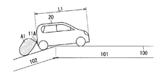
- the transmission / reception units 11A and 11B are attached with the transmission direction inclined downward so that the detection area A1 interferes with the road surface of the road 100.
- a case where such a vehicle 20 travels on the road 100 where the flat road 101 is located at the tip of the uphill 102 will be described with reference to FIGS. 4A and 4B.
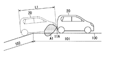
- FIG. 4A shows a state where the vehicle 20 reaches the boundary between the uphill 102 and the flat road 101, the front wheels of the vehicle 20 are on the flat road 101, and the rear wheels are on the uphill 102.
- the rear portion of the vehicle 20 is inclined obliquely upward with respect to the uphill 102.
- the detection area A1 is above the road surface and the determination unit 10 does not erroneously detect the road surface.
- the detection area A1 overlaps the road surface as shown in FIG. 4B. Even during the transition from the state shown in FIG. 4A to the state shown in FIG.
- the detection area A1 may be above the road surface, and the determination unit 10 may not detect the road surface erroneously. That is, it is considered that the non-detection state continues for about the travel time T1 when the vehicle 20 travels at a vehicle speed V1 acquired by the vehicle speed acquisition unit 15 for a distance corresponding to the entire length L1 of the vehicle 20.
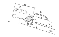
- the vehicle 20 When the vehicle 20 is on the flat road 101 or the downhill 103, the vehicle 20 maintains a certain angle with respect to the road surface. Therefore, when the vehicle 20 is traveling on the flat road 101 or the downhill 103, the road surface overlaps the detection area A1, and the reflected wave from the road surface is input to the transmission / reception units 11A and 11B. Therefore, the determination unit 10 erroneously detects an abnormal approach of an obstacle.
- FIG. 5A shows a state where the vehicle 20 reaches the boundary between the flat road 101 and the downhill 103, the front wheels of the vehicle 20 are on the downhill 103, and the rear wheels are on the flat road 101.
- the rear portion of the vehicle 20 is inclined obliquely upward with respect to the flat road 101.
- the detection area A1 is above the road surface and the determination unit 10 does not erroneously detect the road surface.
- the detection area A1 overlaps the road surface as shown in FIG. 5B. Even during the transition from the state shown in FIG. 5A to the state shown in FIG. 5B, the detection area A1 may be above the road surface, and the determination unit 10 may not detect the road surface erroneously.
- This non-detection state is also considered to continue for about the traveling time T1.
- the obstacle non-detection state continues for about the traveling time T1 depending on the state of the road on which the vehicle 20 travels. It is thought that there is a case.
- the determination unit 10 preferably retains the value of the abnormality determination number as it is if the duration of the non-detection state in which the obstacle is not abnormally approaching is less than the travel time T1.
- the determination unit 10 keeps the value of the abnormality determination number as it is even if the determination unit 10 temporarily enters a non-detection state where no obstacle is detected. Can be held. Therefore, when the determination unit 10 detects the abnormal approach of the obstacle again, the determination unit 10 can restart the count of the number of abnormality determinations and determine the abnormality of the transmission / reception units 11A and 11B at an early stage.
- the determination unit 10 resets the value of the abnormality determination number when the non-detection state in which the obstacle is not abnormally approaching continues for the traveling time T1 or longer. Even when the vehicle travels on the boundary between the uphill 102 and the flat road 101, or on the boundary between the flat road 101 and the downhill 103, the vehicle 20 is expected to pass through the boundary when the travel time T1 elapses. The Therefore, if the non-detection state continues for the traveling time T1 or longer, it can be determined that the transmission / reception units 11A and 11B are attached to the vehicle 20 so that the detection area A1 does not overlap the road surface.
- the transmission / reception units 11A and 11B are abnormal by resetting the value of the abnormality determination count. It is possible to reduce the possibility of false detection.
- the determination unit 10 determines that the transmission direction in which the transmission / reception units 11A and 11B transmit signal waves deviates from the predetermined transmission direction by a predetermined angle or more is an abnormality in the transmission / reception units 11A and 11B. . Thereby, it is possible to detect a state in which the transmission direction in which the transmission / reception units 11A and 11B transmit the signal waves deviate from a predetermined transmission direction by a predetermined angle or more without adding a separate sensor.
- the determination unit 10 uses the inclination information of the vehicle 20 acquired by the acceleration acquisition unit 16 and determines that the object is abnormally approaching in a state where the inclination of the vehicle 20 is equal to or less than a predetermined angle. For example, the number of times may be increased by one.
- the tilt information is information on the tilt angle with respect to the vertical direction.
- the determination unit 10 may increase the number of abnormality determinations by one, for example. Thereby, since the vehicle 20 is inclined, the possibility of erroneous detection that an abnormality has occurred in the transmission / reception units 11A and 11B can be reduced.
- the determination unit 10 determines that the transmission / reception units 11A and 11B are abnormal when the number of times of abnormality detection is equal to or greater than the second reference number and the inclination angle of the vehicle 20 acquired by the acceleration acquisition unit 16 is within a predetermined range. It may be configured to.
- the predetermined range is, for example, within 20 °.
- the obstacle detection device 1 that is an object detection device according to the present embodiment includes the transmission unit 12, the reception unit 13, the measurement unit 14, and the determination unit 10, and is attached to the vehicle 20. .
- the transmission unit 12 intermittently transmits signal waves to the space around the vehicle 20.
- the receiving unit 13 receives a reflected wave generated when the signal wave is reflected by an object.
- the measuring unit 14 measures the distance to the object based on the reflected wave received by the receiving unit 13.
- the determination unit 10 determines that the object is approaching abnormally when the distance measured by the measurement unit 14 is within a predetermined determination distance range.
- the determination unit 10 counts the number of times that the object is determined to be abnormally approached (the above-mentioned abnormality determination number), and when this value reaches a predetermined threshold (second reference number), the transmission unit 12 and the reception unit It is determined that an abnormality has occurred in at least one of the number 13.
- the determination unit 10 counts the number of times that the object is determined to be abnormally approaching, and when this value reaches a predetermined threshold value, the determination unit 10 is at least one of the transmission unit 12 and the reception unit 13. It is determined that there is an abnormality on either side. Therefore, it is not necessary to provide a separate sensor to detect an abnormality in the transmission unit 12 and the reception unit 13, and an abnormality in the transmission unit 12 and the reception unit 13 can be detected with a simple configuration.
- the obstacle detection apparatus 1 preferably further includes a vehicle speed acquisition unit 15 that acquires the vehicle speed of the vehicle 20.
- the determination unit 10 preferably increases the value of the number of times of abnormality determination only when it is determined that the object is abnormally approaching in a state where the vehicle speed acquired by the vehicle speed acquisition unit 15 is outside the predetermined speed range. Thereby, when the vehicle is traveling within a predetermined speed range, the determination unit 10 determines that the object is abnormally approaching even if the distance measured by the measurement unit 14 is equal to or less than the predetermined threshold. Do not count the number of times. Therefore, when an obstacle is detected while parked or parked, the number of times that the object is determined to be abnormally approached exceeds the threshold value, and the transmitter 12 and the receiver 13 are erroneously detected as abnormal. The possibility of being reduced can be reduced.
- the value may be reset.
- the travel time T1 is a time required for traveling at a vehicle speed V1 acquired by the vehicle speed acquisition unit 15 over a distance corresponding to the entire length L1 of the vehicle 20. If the non-detection state continues for a predetermined traveling time T1 or more, it can be determined that the transmission unit 12 and the reception unit 13 are attached to the vehicle 20 at the correct positions. Therefore, resetting the value of the abnormality determination count can reduce the possibility of erroneously detecting an abnormality in the transmission unit 12 and the reception unit 13.
- the determination unit 10 keeps the value of the number of times of abnormality determination as it is when the duration of the non-detection state is less than the travel time T1. Since the non-detection state may continue for about the traveling time T1 depending on the traveling state of the vehicle 20, if the duration of the non-detection state is less than the traveling time T1, the determination unit 10 maintains the value of the abnormality determination number as it is. To do. Thereby, when the abnormal approach of an obstruction is detected again, the abnormality of the transmission part 12 and the receiving part 13 can be detected at an early stage.
- the determination unit 10 may determine that the transmission direction in which the transmission unit 12 transmits the signal wave is shifted from the predetermined transmission direction by a predetermined angle or more as an abnormality of the transmission unit 12. Since it is possible to detect the state in which the transmission unit 12 is attached to the vehicle 20 with the transmission direction of the signal wave deviated by a predetermined angle or more without adding a separate sensor, the abnormality of the transmission unit 12 is detected with a simple configuration. be able to.
- the determination unit 10 increases the number of abnormality determinations under the above-described conditions, there is a possibility of erroneous detection that an abnormality has occurred in the transmission unit 12 and the reception unit 13 due to the vehicle 20 leaning. Can be reduced.
Abstract
Description
10 判断部
11A,11B 送受信部
12 送信部
13 受信部
14 測定部
15 車速取得部
16 加速度取得部
17 出力部
18 記憶部
20 車両
21 リアバンパ
22 フロントバンパ
100 道路
101 平坦路
102 登り坂
103 下り坂
111 入出力面
161 加速度センサ
Claims (9)
- 車両に取り付けられる物体検知装置であって、
前記車両の周囲の空間に信号波を間欠的に送信する送信部と、
前記信号波が物体により反射されることにより生じる反射波を受信する受信部と、
前記受信部が受信した前記反射波に基づいて前記物体までの距離を測定する測定部と、
前記測定部が測定した距離が判定距離範囲内であった場合、前記物体が異常接近していると判断するとともに、前記物体が異常接近していると判断した回数をカウントし、前記回数が閾値に達すると、前記送信部と前記受信部との少なくとも何れか一方に異常が生じていると判断する判断部と、を備えた、
物体検知装置。 - 前記車両の車速を取得する車速取得部をさらに備え、
前記判断部は、前記車速取得部が取得した車速が所定の速度範囲外である状態で、前記物体が異常接近していると判断した場合のみ、前記回数を増加させる、
請求項1に記載の物体検知装置。 - 前記判断部は、前記物体が異常接近していると判断していない非検知状態が、前記車両の全長に相当する距離を前記車速取得部で取得した車速で走行した場合の走行時間以上継続すると、前記回数をリセットする、
請求項2に記載の物体検知装置。 - 前記判断部は、前記非検知状態の継続時間が前記走行時間未満であれば、前記回数をそのまま保持する、
請求項3に記載の物体検知装置。 - 前記車両の車速を取得する車速取得部をさらに備え、
前記判断部は、前記物体が異常接近していると判断していない非検知状態が、前記車両の全長に相当する距離を前記車速取得部で取得した車速で走行した場合の走行時間以上継続すると、前記回数をリセットする、
請求項1に記載の物体検知装置。 - 前記判断部は、前記非検知状態の継続時間が前記走行時間未満であれば、前記回数をそのまま保持する、
請求項5に記載の物体検知装置。 - 前記判断部は、前記送信部が前記信号波を送信する送信方向が、所定の送信方向から所定角度以上ずれた状態を、前記送信部の異常と判断する、
請求項1に記載の物体検知装置。 - 前記車両の鉛直方向に対する傾き情報を前記判断部に出力する加速度取得部をさらに備え、
前記判断部は、前記傾き情報を用いて、前記車両の傾きが所定角度以下となる状態で、前記物体が異常接近していると判断した場合のみ、前記回数を増加させる、
請求項7に記載の物体検知装置。 - 前記加速度取得部は、前記送信部と、前記受信部とのいずれかに設けられた加速度センサを有するか、または、前記車両に設けられた加速度センサと接続されている、
請求項8に記載の物体検知装置。
Priority Applications (4)
| Application Number | Priority Date | Filing Date | Title |
|---|---|---|---|
| US15/111,796 US10180491B2 (en) | 2014-02-05 | 2015-01-15 | Object detection device |
| EP15746491.8A EP3104192A4 (en) | 2014-02-05 | 2015-01-15 | Object detection device |
| JP2015561197A JP6413097B2 (ja) | 2014-02-05 | 2015-01-15 | 物体検知装置 |
| CN201580007274.6A CN105960597A (zh) | 2014-02-05 | 2015-01-15 | 物体探测装置 |
Applications Claiming Priority (2)
| Application Number | Priority Date | Filing Date | Title |
|---|---|---|---|
| JP2014020686 | 2014-02-05 | ||
| JP2014-020686 | 2014-02-05 |
Publications (1)
| Publication Number | Publication Date |
|---|---|
| WO2015118804A1 true WO2015118804A1 (ja) | 2015-08-13 |
Family
ID=53777619
Family Applications (1)
| Application Number | Title | Priority Date | Filing Date |
|---|---|---|---|
| PCT/JP2015/000149 WO2015118804A1 (ja) | 2014-02-05 | 2015-01-15 | 物体検知装置 |
Country Status (5)
| Country | Link |
|---|---|
| US (1) | US10180491B2 (ja) |
| EP (1) | EP3104192A4 (ja) |
| JP (1) | JP6413097B2 (ja) |
| CN (1) | CN105960597A (ja) |
| WO (1) | WO2015118804A1 (ja) |
Cited By (8)
| Publication number | Priority date | Publication date | Assignee | Title |
|---|---|---|---|---|
| CN105844961A (zh) * | 2016-01-07 | 2016-08-10 | 乐卡汽车智能科技(北京)有限公司 | 测量距离的方法、装置和系统 |
| CN106569213A (zh) * | 2016-10-21 | 2017-04-19 | 奇瑞汽车股份有限公司 | 一种汽车静态防碰撞系统及其控制方法 |
| WO2017159170A1 (ja) * | 2016-03-18 | 2017-09-21 | パナソニックIpマネジメント株式会社 | センサ取り付け状態判定装置およびセンサ取り付け状態判定方法 |
| JP2018036231A (ja) * | 2016-09-02 | 2018-03-08 | 株式会社デンソー | 物体検知装置 |
| WO2018066391A1 (ja) * | 2016-10-04 | 2018-04-12 | 株式会社デンソー | 物体検出センサの軸ずれ判定方法 |
| JP2019519051A (ja) * | 2016-04-07 | 2019-07-04 | 上海三思▲電▼子工程有限公司Shanghai Sansi Electronic Engineering Co.,Ltd. | 知的照明システム、照明デバイス、車両、車載端末、車両運転支援システム及び車両運転支援方法 |
| JP2022154276A (ja) * | 2021-03-30 | 2022-10-13 | 本田技研工業株式会社 | 自己診断装置 |
| WO2023282097A1 (ja) * | 2021-07-06 | 2023-01-12 | 株式会社アイシン | 物体検出装置 |
Families Citing this family (8)
| Publication number | Priority date | Publication date | Assignee | Title |
|---|---|---|---|---|
| JP6512164B2 (ja) * | 2016-04-22 | 2019-05-15 | 株式会社デンソー | 物体検出装置、物体検出方法 |
| US10408921B2 (en) * | 2016-10-28 | 2019-09-10 | Ford Global Technologies, Llc | Vehicle detection of external objects |
| WO2018155142A1 (ja) * | 2017-02-21 | 2018-08-30 | 日立オートモティブシステムズ株式会社 | 車両制御装置 |
| JP6686961B2 (ja) * | 2017-04-24 | 2020-04-22 | 株式会社デンソー | 物体検知装置 |
| CN112470027A (zh) * | 2018-07-27 | 2021-03-09 | 三菱电机株式会社 | 物体检测装置的控制装置、物体检测装置和物体检测程序 |
| CN109581390A (zh) * | 2018-11-27 | 2019-04-05 | 北京纵目安驰智能科技有限公司 | 基于超声波雷达的地形检测方法、系统、终端和存储介质 |
| KR20210136631A (ko) * | 2020-05-08 | 2021-11-17 | 주식회사 만도모빌리티솔루션즈 | 차량용 레이더의 수직 장착 오정렬 감지 장치, 방법 및 그를 포함하는 레이더 장치 |
| JP2022122196A (ja) * | 2021-02-09 | 2022-08-22 | 株式会社アイシン | 物体検出装置及び移動体制御装置 |
Citations (5)
| Publication number | Priority date | Publication date | Assignee | Title |
|---|---|---|---|---|
| JPH1114747A (ja) * | 1997-06-25 | 1999-01-22 | Honda Motor Co Ltd | 車両の物体検知装置 |
| JP2004085258A (ja) * | 2002-08-23 | 2004-03-18 | Hitachi Ltd | レーダ装置 |
| JP2007178183A (ja) * | 2005-12-27 | 2007-07-12 | Mazda Motor Corp | 車両の障害物検知装置 |
| JP2008040646A (ja) * | 2006-08-03 | 2008-02-21 | Honda Motor Co Ltd | 車両制御装置 |
| JP2011002346A (ja) * | 2009-06-19 | 2011-01-06 | Fujitsu Ten Ltd | 信号処理装置、及びレーダ装置 |
Family Cites Families (16)
| Publication number | Priority date | Publication date | Assignee | Title |
|---|---|---|---|---|
| JP3331882B2 (ja) * | 1995-12-27 | 2002-10-07 | 株式会社デンソー | 車両用障害物検出装置の中心軸偏向量算出装置,中心軸偏向量補正装置,および車間制御装置 |
| US6230107B1 (en) * | 1996-03-29 | 2001-05-08 | Komatsu Ltd. | Vehicle speed detection system |
| DE19650863C1 (de) * | 1996-12-07 | 1998-04-16 | Bosch Gmbh Robert | Verfahren und Vorrichtung zur Erkennung einer vertikalen Dejustierung eines Abstandssensors |
| US6087975A (en) | 1997-06-25 | 2000-07-11 | Honda Giken Kogyo Kabushiki Kaisha | Object detecting system for vehicle |
| JP3428009B2 (ja) * | 1998-07-03 | 2003-07-22 | トヨタ自動車株式会社 | 車両用レーダ装置 |
| JP4740449B2 (ja) * | 2000-12-27 | 2011-08-03 | 富士通テン株式会社 | 車載用レーダの上下軸ずれ検出装置 |
| DE60222471T2 (de) * | 2002-01-18 | 2008-06-12 | Hitachi, Ltd. | Radareinrichtung |
| JP4593968B2 (ja) * | 2004-05-14 | 2010-12-08 | キヤノン株式会社 | 位置姿勢計測方法および装置 |
| US7667636B2 (en) | 2006-08-03 | 2010-02-23 | Honda Motor Co., Ltd. | Vehicle control system |
| US7813851B2 (en) * | 2007-02-21 | 2010-10-12 | Autoliv Asp, Inc. | Sensing misalignment detection and estimation system |
| KR101053855B1 (ko) * | 2009-01-22 | 2011-08-03 | 주식회사 만도 | 센서 수직 얼라이먼트 조절 장치 및 센서 |
| US20100188932A1 (en) * | 2009-01-28 | 2010-07-29 | Darwin Mitchel Hanks | Low Power Sensor System |
| US8775064B2 (en) * | 2011-05-10 | 2014-07-08 | GM Global Technology Operations LLC | Sensor alignment process and tools for active safety vehicle applications |
| US8957807B2 (en) * | 2011-12-14 | 2015-02-17 | Ford Global Technologies, Llc | Internal multi-axis G sensing used to align an automotive forward radar to the vehicle's thrust axis |
| US8930063B2 (en) * | 2012-02-22 | 2015-01-06 | GM Global Technology Operations LLC | Method for determining object sensor misalignment |
| JP6430778B2 (ja) * | 2014-10-22 | 2018-11-28 | 株式会社デンソー | 物体検知装置 |
-
2015
- 2015-01-15 JP JP2015561197A patent/JP6413097B2/ja active Active
- 2015-01-15 WO PCT/JP2015/000149 patent/WO2015118804A1/ja active Application Filing
- 2015-01-15 CN CN201580007274.6A patent/CN105960597A/zh active Pending
- 2015-01-15 EP EP15746491.8A patent/EP3104192A4/en not_active Withdrawn
- 2015-01-15 US US15/111,796 patent/US10180491B2/en active Active
Patent Citations (5)
| Publication number | Priority date | Publication date | Assignee | Title |
|---|---|---|---|---|
| JPH1114747A (ja) * | 1997-06-25 | 1999-01-22 | Honda Motor Co Ltd | 車両の物体検知装置 |
| JP2004085258A (ja) * | 2002-08-23 | 2004-03-18 | Hitachi Ltd | レーダ装置 |
| JP2007178183A (ja) * | 2005-12-27 | 2007-07-12 | Mazda Motor Corp | 車両の障害物検知装置 |
| JP2008040646A (ja) * | 2006-08-03 | 2008-02-21 | Honda Motor Co Ltd | 車両制御装置 |
| JP2011002346A (ja) * | 2009-06-19 | 2011-01-06 | Fujitsu Ten Ltd | 信号処理装置、及びレーダ装置 |
Non-Patent Citations (1)
| Title |
|---|
| See also references of EP3104192A4 * |
Cited By (16)
| Publication number | Priority date | Publication date | Assignee | Title |
|---|---|---|---|---|
| CN105844961A (zh) * | 2016-01-07 | 2016-08-10 | 乐卡汽车智能科技(北京)有限公司 | 测量距离的方法、装置和系统 |
| CN109903586A (zh) * | 2016-01-07 | 2019-06-18 | 法法汽车(中国)有限公司 | 测量距离的方法、装置和系统 |
| US10571553B2 (en) | 2016-03-18 | 2020-02-25 | Panasonic Intellectual Property Management Co., Ltd. | Sensor mounting state determination device and sensor mounting state determination method |
| WO2017159170A1 (ja) * | 2016-03-18 | 2017-09-21 | パナソニックIpマネジメント株式会社 | センサ取り付け状態判定装置およびセンサ取り付け状態判定方法 |
| JP2017167096A (ja) * | 2016-03-18 | 2017-09-21 | パナソニックIpマネジメント株式会社 | 取り付け状態判定装置および取り付け状態判定方法 |
| JP2019519051A (ja) * | 2016-04-07 | 2019-07-04 | 上海三思▲電▼子工程有限公司Shanghai Sansi Electronic Engineering Co.,Ltd. | 知的照明システム、照明デバイス、車両、車載端末、車両運転支援システム及び車両運転支援方法 |
| CN109661593A (zh) * | 2016-09-02 | 2019-04-19 | 株式会社电装 | 物体检测装置 |
| WO2018043306A1 (ja) * | 2016-09-02 | 2018-03-08 | 株式会社デンソー | 物体検知装置 |
| JP2018036231A (ja) * | 2016-09-02 | 2018-03-08 | 株式会社デンソー | 物体検知装置 |
| US11487007B2 (en) * | 2016-09-02 | 2022-11-01 | Denso Corporation | Object detection device |
| CN109661593B (zh) * | 2016-09-02 | 2022-11-22 | 株式会社电装 | 物体检测装置 |
| JP2018059783A (ja) * | 2016-10-04 | 2018-04-12 | 株式会社デンソー | 物体検出センサの軸ずれ判定方法 |
| WO2018066391A1 (ja) * | 2016-10-04 | 2018-04-12 | 株式会社デンソー | 物体検出センサの軸ずれ判定方法 |
| CN106569213A (zh) * | 2016-10-21 | 2017-04-19 | 奇瑞汽车股份有限公司 | 一种汽车静态防碰撞系统及其控制方法 |
| JP2022154276A (ja) * | 2021-03-30 | 2022-10-13 | 本田技研工業株式会社 | 自己診断装置 |
| WO2023282097A1 (ja) * | 2021-07-06 | 2023-01-12 | 株式会社アイシン | 物体検出装置 |
Also Published As
| Publication number | Publication date |
|---|---|
| US10180491B2 (en) | 2019-01-15 |
| CN105960597A (zh) | 2016-09-21 |
| JPWO2015118804A1 (ja) | 2017-03-23 |
| US20160334505A1 (en) | 2016-11-17 |
| EP3104192A4 (en) | 2017-03-08 |
| EP3104192A1 (en) | 2016-12-14 |
| JP6413097B2 (ja) | 2018-10-31 |
Similar Documents
| Publication | Publication Date | Title |
|---|---|---|
| JP6413097B2 (ja) | 物体検知装置 | |
| JP6246465B2 (ja) | 路肩の空間認知方法及びシステム | |
| US7552012B2 (en) | Device for detecting objects in the blind spot of a vehicle | |
| US10571564B2 (en) | Method for detecting at least one object in a surrounding area of a motor vehicle, driver assistance system and motor vehicle | |
| KR20170114054A (ko) | 충돌방지장치 및 충돌방지방법 | |
| JP6089585B2 (ja) | 障害物検知装置 | |
| CN106537175B (zh) | 用于运载工具的周围环境对象的声学检查的设备和方法 | |
| CN103109312A (zh) | 一种用于警告机动车辆的驾驶员在靠近车辆的侧板的侧部区域中存在障碍物的方法以及具有驾驶员辅助系统的机动车辆 | |
| US8823578B2 (en) | Driving assist apparatus | |
| JP6577767B2 (ja) | 物体検知装置及び物体検知方法 | |
| JP6140755B2 (ja) | 距離決定の装置と方法 | |
| JP7122101B2 (ja) | 車両用障害物検知装置 | |
| JP2008536738A (ja) | 乗員保護装置に対するトリガ信号生成のための方法及び装置 | |
| JP2008514907A (ja) | 駐車余地を測定する赤外線センサ及び車両に対する周囲の状況の監視 | |
| JP2013061690A (ja) | 車両用障害物検出システム | |
| US20150097702A1 (en) | Blind spot sensing apparatus and method | |
| JP2015132511A (ja) | 路面監視装置および電動カート | |
| CN111038380A (zh) | 前向碰撞预警方法和系统 | |
| JP2011242170A (ja) | 車両用レーダ装置 | |
| KR101105338B1 (ko) | 자동차 속도 감지 시스템 | |
| JP2004083009A (ja) | 自動二輪車における傾斜検出方法および装置 | |
| JP3171767B2 (ja) | 衝突予知システム | |
| KR102075927B1 (ko) | 주차 보조 장치 및 방법 | |
| KR101544850B1 (ko) | 차량의 측후방 물체 검출장치 | |
| CN110967689B (zh) | 一种目标对象高度的确定方法、装置及车载雷达设备 |
Legal Events
| Date | Code | Title | Description |
|---|---|---|---|
| 121 | Ep: the epo has been informed by wipo that ep was designated in this application |
Ref document number: 15746491 Country of ref document: EP Kind code of ref document: A1 |
|
| WWE | Wipo information: entry into national phase |
Ref document number: 15111796 Country of ref document: US |
|
| ENP | Entry into the national phase |
Ref document number: 2015561197 Country of ref document: JP Kind code of ref document: A |
|
| REEP | Request for entry into the european phase |
Ref document number: 2015746491 Country of ref document: EP |
|
| WWE | Wipo information: entry into national phase |
Ref document number: 2015746491 Country of ref document: EP |
|
| NENP | Non-entry into the national phase |
Ref country code: DE |