WO2015118719A1 - 内視鏡用のガイド部材のための保持機構と内視鏡 - Google Patents
内視鏡用のガイド部材のための保持機構と内視鏡 Download PDFInfo
- Publication number
- WO2015118719A1 WO2015118719A1 PCT/JP2014/075910 JP2014075910W WO2015118719A1 WO 2015118719 A1 WO2015118719 A1 WO 2015118719A1 JP 2014075910 W JP2014075910 W JP 2014075910W WO 2015118719 A1 WO2015118719 A1 WO 2015118719A1
- Authority
- WO
- WIPO (PCT)
- Prior art keywords
- holding
- guide member
- disposed
- treatment instrument
- endoscope
- Prior art date
Links
Images


Classifications
-
- A—HUMAN NECESSITIES
- A61—MEDICAL OR VETERINARY SCIENCE; HYGIENE
- A61B—DIAGNOSIS; SURGERY; IDENTIFICATION
- A61B1/00—Instruments for performing medical examinations of the interior of cavities or tubes of the body by visual or photographical inspection, e.g. endoscopes; Illuminating arrangements therefor
- A61B1/273—Instruments for performing medical examinations of the interior of cavities or tubes of the body by visual or photographical inspection, e.g. endoscopes; Illuminating arrangements therefor for the upper alimentary canal, e.g. oesophagoscopes, gastroscopes
- A61B1/2736—Gastroscopes
-
- A—HUMAN NECESSITIES
- A61—MEDICAL OR VETERINARY SCIENCE; HYGIENE
- A61B—DIAGNOSIS; SURGERY; IDENTIFICATION
- A61B1/00—Instruments for performing medical examinations of the interior of cavities or tubes of the body by visual or photographical inspection, e.g. endoscopes; Illuminating arrangements therefor
- A61B1/00064—Constructional details of the endoscope body
- A61B1/00066—Proximal part of endoscope body, e.g. handles
-
- A—HUMAN NECESSITIES
- A61—MEDICAL OR VETERINARY SCIENCE; HYGIENE
- A61B—DIAGNOSIS; SURGERY; IDENTIFICATION
- A61B1/00—Instruments for performing medical examinations of the interior of cavities or tubes of the body by visual or photographical inspection, e.g. endoscopes; Illuminating arrangements therefor
- A61B1/00131—Accessories for endoscopes
- A61B1/00137—End pieces at either end of the endoscope, e.g. caps, seals or forceps plugs
-
- A—HUMAN NECESSITIES
- A61—MEDICAL OR VETERINARY SCIENCE; HYGIENE
- A61B—DIAGNOSIS; SURGERY; IDENTIFICATION
- A61B1/00—Instruments for performing medical examinations of the interior of cavities or tubes of the body by visual or photographical inspection, e.g. endoscopes; Illuminating arrangements therefor
- A61B1/00131—Accessories for endoscopes
- A61B1/0014—Fastening element for attaching accessories to the outside of an endoscope, e.g. clips, clamps or bands
-
- A—HUMAN NECESSITIES
- A61—MEDICAL OR VETERINARY SCIENCE; HYGIENE
- A61B—DIAGNOSIS; SURGERY; IDENTIFICATION
- A61B1/00—Instruments for performing medical examinations of the interior of cavities or tubes of the body by visual or photographical inspection, e.g. endoscopes; Illuminating arrangements therefor
- A61B1/00163—Optical arrangements
- A61B1/00174—Optical arrangements characterised by the viewing angles
- A61B1/00177—Optical arrangements characterised by the viewing angles for 90 degrees side-viewing
-
- A—HUMAN NECESSITIES
- A61—MEDICAL OR VETERINARY SCIENCE; HYGIENE
- A61B—DIAGNOSIS; SURGERY; IDENTIFICATION
- A61B1/00—Instruments for performing medical examinations of the interior of cavities or tubes of the body by visual or photographical inspection, e.g. endoscopes; Illuminating arrangements therefor
- A61B1/012—Instruments for performing medical examinations of the interior of cavities or tubes of the body by visual or photographical inspection, e.g. endoscopes; Illuminating arrangements therefor characterised by internal passages or accessories therefor
- A61B1/018—Instruments for performing medical examinations of the interior of cavities or tubes of the body by visual or photographical inspection, e.g. endoscopes; Illuminating arrangements therefor characterised by internal passages or accessories therefor for receiving instruments
-
- A—HUMAN NECESSITIES
- A61—MEDICAL OR VETERINARY SCIENCE; HYGIENE
- A61M—DEVICES FOR INTRODUCING MEDIA INTO, OR ONTO, THE BODY; DEVICES FOR TRANSDUCING BODY MEDIA OR FOR TAKING MEDIA FROM THE BODY; DEVICES FOR PRODUCING OR ENDING SLEEP OR STUPOR
- A61M25/00—Catheters; Hollow probes
- A61M25/01—Introducing, guiding, advancing, emplacing or holding catheters
- A61M2025/0177—Introducing, guiding, advancing, emplacing or holding catheters having external means for receiving guide wires, wires or stiffening members, e.g. loops, clamps or lateral tubes
-
- A—HUMAN NECESSITIES
- A61—MEDICAL OR VETERINARY SCIENCE; HYGIENE
- A61M—DEVICES FOR INTRODUCING MEDIA INTO, OR ONTO, THE BODY; DEVICES FOR TRANSDUCING BODY MEDIA OR FOR TAKING MEDIA FROM THE BODY; DEVICES FOR PRODUCING OR ENDING SLEEP OR STUPOR
- A61M25/00—Catheters; Hollow probes
- A61M25/01—Introducing, guiding, advancing, emplacing or holding catheters
- A61M25/09—Guide wires
- A61M2025/09125—Device for locking a guide wire in a fixed position with respect to the catheter or the human body
Definitions
- the present invention relates to a holding mechanism for a guide member for holding a guide member for an endoscope for guiding a treatment tool protruding from an opening provided in an insertion portion of the endoscope to a subject, and the holding mechanism.
- the present invention relates to an endoscope having a mechanism.
- the treatment instrument has a cylindrical member that is disposed at the distal end of the treatment instrument and through which the guide member can be inserted.
- the tubular member can slide the guide member so that the guide member passes through the tubular member. By this sliding, the cylindrical member functions as a monorail portion, and the treatment instrument can move along the guide member.
- the guide member is formed by a thin linear member, for example.
- the guide member is inserted into the treatment instrument insertion channel communicating with the treatment instrument insertion port through the treatment instrument insertion port from the forceps plug disposed in the grip portion of the endoscope.
- tip part of a guide member penetrates a treatment tool penetration channel, and protrudes from the front-end
- the tip opening is disposed on the side surface of the tip. For this reason, the front-end
- the proximal end portion of the guide member is exposed to the outside of the endoscope from the treatment instrument insertion port.
- the treatment instrument moves along the guide member by the tubular member so that the guide member penetrates the tubular member.
- the treatment instrument is guided by the guide member and is inserted into the treatment instrument insertion channel from the forceps plug portion via the treatment instrument insertion port.
- the treatment instrument is guided by the guide member, passes through the treatment instrument insertion channel, protrudes laterally from the distal end opening, and reaches the subject.
- the treatment tool is guided to the subject by the guide member.
- Such a guide member is disclosed in Patent Document 1 and Patent Document 2, for example.
- the guide member is fixed and the proximal end portion of the guide member is held by a holding member separate from the endoscope so that the guide member is prevented from being displaced.
- the holding member is attached to the treatment instrument insertion port so as to be detachable from the endoscope.
- Patent Document 1 and Patent Document 2 since the holding member is separate from the endoscope, it takes time to attach the holding member to the endoscope. Since the holding member is separate from the endoscope, the cost is high. When the treatment instrument advances and retreats along the axial direction of the treatment instrument, there is a risk that the guide member may be displaced due to advance and retreat movement.
- the present invention has been made in view of these circumstances, and a holding mechanism for a guide member for an endoscope that suppresses the mounting effort, is inexpensive, and prevents the guide member from being displaced, and the holding mechanism. It is an object to provide an endoscope having the following.
- a holding mechanism for a guide member for an endoscope is inserted into the lumen through an insertion portion of an endoscope that is inserted into the lumen, and is disposed in the insertion portion.
- a holding mechanism for an endoscope guide member that holds a guide member that projects from an opening and guides a treatment instrument, and operates the endoscope to be connected to a proximal end portion of the insertion portion
- a first portion that is disposed in the operation portion and that holds the portion exposed from the endoscope on the proximal end side of the guide member in the state where the distal end portion of the guide member protrudes from the opening portion.
- the guide member At a position different from the first holding portion in the operation portion, and at a position different from the portion held by the first holding portion on the proximal end side of the guide member, And the guide member in an orientation different from the orientation of the first holding portion. It includes a second holding portion for lifting, a.
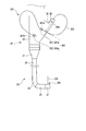
- FIG. 1A is a schematic perspective view of a side-view type endoscope according to the first embodiment of the present invention.
- FIG. 1B is a top view of the hard tip portion.
- FIG. 2A is a schematic diagram of a holding mechanism for an endoscope guide member according to the first embodiment.
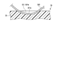
- FIG. 2B is a longitudinal sectional view showing an example of the configuration of the groove.
- FIG. 2C is a cross-sectional view illustrating an example of the configuration of the groove.
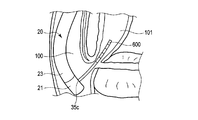
- FIG. 3A is a diagram illustrating that a contrast tube is inserted into a bile duct.
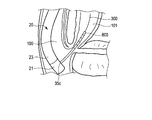
- FIG. 3B is a diagram illustrating that the guide member is inserted into the bile duct.
- FIG. 1A is a schematic perspective view of a side-view type endoscope according to the first embodiment of the present invention.
- FIG. 1B is a top view of the hard tip portion.
- FIG. 2A is a schematic diagram of a holding mechanism for an endoscope guide member according to
- FIG. 3C is a diagram illustrating that the treatment tool is inserted into the bile duct by the guide of the guide member.
- FIG. 3D is a perspective view of a cylindrical member through which the guide member is inserted.
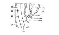
- FIG. 4A is a schematic diagram of a holding mechanism in Modification 1 of the first embodiment.
- FIG. 4B is a top view of the holding portion including the forceps plug portion shown in FIG. 4A.
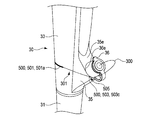
- FIG. 5A is a schematic perspective view of a holding mechanism according to the second embodiment.
- FIG. 5B is a side view of the periphery of the holding unit.
- FIG. 5C is a perspective view of the periphery of the holding unit.
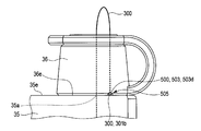
- FIG. 6 is a side view of the vicinity of the holding portion in the holding mechanism according to the first modification of the second embodiment.
- FIG. 7 is a side view of the periphery of the holding unit in the holding mechanism according to the second modification of the second embodiment.
- FIGS. 1A, 1B, 2A, 2B, 2C, 3A, 3B, 3C, and 3D Note that, for example, in FIG. 1A, illustration of a holding mechanism 500 for an endoscope guide member is omitted, and in some drawings, illustration of some members is omitted for clarity of illustration. Yes.
- An endoscope 10 as shown in FIG. 1A is, for example, a side-view type endoscope. As shown in FIG. 1A, an endoscope 10 is connected to a hollow elongated insertion portion 20 to be inserted into a lumen such as a body cavity of a patient, and a proximal end portion of the insertion portion 20 to operate the endoscope 10. And an operation unit 30 to be operated.
- the insertion portion 20 includes a distal end hard portion 21, a bending portion 23, and a flexible tube portion 25 from the distal end portion side of the insertion portion 20 toward the proximal end portion side of the insertion portion 20.
- the proximal end portion of the distal rigid portion 21 is connected to the distal end portion of the bending portion 23, and the proximal end portion of the bending portion 23 is connected to the distal end portion of the flexible tube portion 25.
- the distal end hard portion 21 is the distal end portion of the insertion portion 20 and is hard and does not bend. The configuration of the distal end hard portion 21 will be described later.
- the bending portion 23 is bent in a desired direction, for example, up, down, left, and right, by an operation of a bending operation unit 37 described later.
- a bending operation unit 37 described later.
- the bending portion 23 is bent, the position and orientation of the distal end hard portion 21 are changed.
- illumination light (not shown) is illuminated on the observation object, and the observation object is captured in the observation field.
- the observation object is, for example, an affected part or a lesion part in a subject (for example, a body cavity).
- the flexible tube portion 25 has desired flexibility. Therefore, the flexible tube portion 25 is bent by an external force.
- the flexible tube portion 25 is a tubular member that extends from a main body portion 31 described later in the operation portion 30.
- the operation unit 30 is connected to a main body part 31 from which the flexible tube part 25 extends and a base end part of the main body part 31 and is held by an operator who operates the endoscope 10. And a universal cord 41 connected to the grip portion 33.
- the gripping part 33 includes a treatment instrument insertion part 35, a bending operation part 37 for bending the bending part 23, and a switch part 39.
- the treatment instrument insertion portion 35 is disposed on the distal end side of the grip portion 33, and the bending operation portion 37 and the switch portion 39 are disposed on the proximal end portion side of the grip portion 33.
- Treatment instrument insertion part 35 As shown in FIG. 1A, the treatment instrument insertion portion 35 is branched with respect to the grasping portion 33. For this reason, the central axis direction of the treatment instrument insertion portion 35 is inclined with respect to the central axis direction of the grasping portion 33. As shown in FIG. 1A, the treatment instrument insertion portion 35 is disposed at the end of the treatment instrument insertion portion 35, and is disposed so that a guide member 300 and a treatment instrument 400 described later are inserted into the endoscope 10. It has a treatment instrument insertion port 35a.
- the treatment instrument insertion port 35a is connected to a proximal end portion of a treatment instrument insertion channel (not shown).
- the treatment instrument insertion channel is disposed inside the insertion portion 20, and is disposed from the flexible tube portion 25 through the bending portion 23 to the distal end hard portion 21.
- the distal end portion of the treatment instrument insertion channel communicates with a distal end opening portion 35c (see FIG. 1B) disposed in the distal end rigid portion 21.
- the treatment instrument insertion port 35a is an insertion slot for inserting the guide member 300 and the treatment instrument 400 into the treatment instrument insertion channel. As shown in FIG.
- the central axis of the treatment instrument insertion port portion 35 a is disposed coaxially with the central axis of the treatment instrument insertion portion 35, and is therefore inclined with respect to the central axis of the grasping portion 33. . Further, the central axis direction is inclined with respect to the central axis direction of the grip portion 33.
- the treatment instrument insertion portion 35 further includes a cylindrical forceps plug portion 36 disposed in the treatment instrument insertion portion 35.
- the forceps plug portion 36 is made of a resin such as rubber, for example.
- the central axis of the forceps plug portion 36 is disposed coaxially with the central axis of the treatment instrument insertion port portion 35a. For this reason, the forceps plug portion 36 is inclined with respect to the grip portion 33.
- the forceps plug portion 36 communicates with the treatment instrument insertion channel via the treatment instrument insertion port 35a.
- the guide member 300 shown in FIG. 2A and the treatment instrument 400 shown in FIG. 3C are inserted into the treatment instrument insertion channel from the forceps plug portion 36 via the treatment instrument insertion port 35a and pushed to the distal end hard portion 21 side. As shown in FIGS. 2A, 3B, and 3C, the guide member 300 and the treatment instrument 400 protrude from the distal end opening 35c.
- the bending operation section 37 includes a left / right bending operation knob 37a for bending the bending section 23 left and right, a vertical bending operation knob 37b for bending the bending section 23 up and down, and a curved bending section 23. And a fixing knob 37c for fixing the position.
- the switch unit 39 includes a suction switch 39a, an air / water supply switch 39b, and various switches 39c for endoscopic photography.
- the suction switch 39a, the air / water supply switch 39b, and the various switches 39c are operated by the operator's hand when the grip portion 33 is gripped by the operator.
- the suction switch 39a is operated when the endoscope 10 sucks mucus, fluid, or the like through the treatment instrument insertion channel that also serves as a suction channel from the distal end opening 35c that also serves as a suction opening.
- the air supply / water supply switch 39b is used to supply fluid from an air supply tube (not shown) and an air supply / water supply tube (not shown) and a water supply tube in order to secure an observation field of view of the imaging unit 70 at the distal end hard portion 21. And when air is supplied from the air / water supply tube.
- the fluid includes water and gas.
- the air supply tube, the water supply tube, and the air / water supply tube are disposed from the insertion portion 20 to the universal cord 41 through the main body portion 31 and the grip portion 33 in the endoscope 10. .
- the universal cord 41 extends from the side surface of the grip portion 33.
- the universal cord 41 has a connection connector 41 a that is detachable from the control device 14.
- the control device 14 controls the endoscope 10.
- the control device 14 includes an image processing unit that processes an image captured by the imaging unit.
- the control device 14 is connected to a display unit 16 that is a display unit that displays an image captured by the imaging unit.
- the distal end hard portion 21 has a main body portion 211 and a cap portion 213.
- the main body 211 is made of a metal such as stainless steel.
- the base end portion of the main body portion 211 is connected to the distal end portion of the bending portion 23.
- the main body 211 has a cylindrical shape, for example.
- a part of outer peripheral surface of the main-body part 211 is planarly formed by notching a part of the main-body part 211.
- the main body 211 has the flat surface portion 211a and the wall surface portion 211b orthogonal to the flat surface portion 211a.
- the cap portion 213 covers the main body portion 211 except for the flat surface portion 211a and the wall surface portion 211b.
- the cap part 213 is watertightly bonded to the main body part 211.
- the cap part 213 is fixed with respect to the main body part 211.
- the cap part 213 has electrical insulation.
- the main body 211 As shown in FIG. 1B, the main body 211 is mounted with a tip opening 35c, an air / water supply nozzle 61, an imaging unit 70, and an illumination unit 80.
- the tip opening 35c is recessed with respect to the flat portion 211a. That is, the tip opening 35 c opens toward the side of the main body 211.
- the distal end opening 35c houses a treatment instrument raising base 51 that can be remotely rocked in accordance with the raising operation on the hand side.
- the treatment instrument elevator 51 is connected to an elevator operating unit (not shown) via an elevator operation wire (not shown) that passes through the insertion unit 20.
- the elevator base operation unit is disposed, for example, on the grip 33 that indicates the proximal side. When the raising base operation unit pushes and pulls the raising operation wire, the treatment instrument raising base 51 freely rotates with respect to the main body 211 about a support shaft (not shown).
- the treatment instrument raising base 51 is inverted with respect to the flat surface portion 211a of the main body portion 211 and protrudes from the storage position stored in the main body portion 211 and the flat surface portion 211a of the main body portion 211, that is, the distal end opening portion 35c. Swing between the raised position and the raised position.
- the treatment instrument raising base 51 is swung according to the raising operation, and guides the treatment instrument 400 to protrude from the distal end opening 35 c to the side of the main body 211.
- the treatment instrument raising base 51 may include a treatment instrument guide groove 53 that guides the treatment instrument 400 from the main body 211 to the outside.
- the treatment instrument guide groove 53 is disposed at the center of the treatment instrument elevator base 51 and is further disposed along the longitudinal axis direction of the treatment instrument elevator base 51.
- the air / water supply nozzle 61 is disposed on the wall surface portion 211 b of the main body portion 211.
- the air / water supply nozzle 61 is collinear with the observation window 71 of the imaging unit 70 in the axial direction of the insertion unit 20 so as to supply air / water to the observation window 71 of the imaging unit 70, for example. It is arranged.
- the air / water supply nozzle 61 including the wall surface portion 211b is disposed closer to the proximal end portion of the main body portion 211 than the observation window portion 71.
- the air / water supply nozzle 61 is connected to the air supply tube and the water supply tube via an air / water supply tube (not shown) that is inserted through the insertion portion 20.
- an air / water supply tube (not shown) that is inserted through the insertion portion 20.
- Imaging unit 70 As shown in FIG. 1B, the imaging unit 70 has an observation window 71, a prism unit (not shown), and an imaging unit (not shown).
- observation window 71 As shown in FIG. 1B, the reflected light reflected from the observation object is incident on the observation window portion 71 in the side-viewing observation. For this reason, the observation window part 71 is arrange
- a prism unit (not shown) reflects the reflected light that has passed through the observation window 71 to change the progress of the reflected light.
- the prism portion is disposed inside the main body portion 211 so that the central axis of the prism portion is disposed substantially coaxially with the central axis of the observation window portion 71.
- the prism portion is disposed inside the main body 211 so as to face the observation window portion 71 in the orthogonal direction.
- An imaging unit (not shown) is disposed adjacent to the prism unit in the axial direction of the insertion unit 20. That is, the imaging unit is arranged on the substantially same straight line as the prism unit in the axial direction of the insertion unit 20. The imaging unit is disposed along the axial direction of the insertion unit 20 together with the prism unit. Such an imaging unit is disposed inside the main body 211 so as to face the prism unit.
- the imaging unit includes an objective optical system (lens system) (not shown) having an objective lens group having a predetermined image surface distortion, an imaging element (not shown) such as a CCD disposed at an imaging position of the objective optical system, A connection circuit board that does not.
- the objective optical system (lens system), the image sensor, and the connection circuit board are integrated.
- An imaging cable (not shown) such as a signal line is connected to the connection circuit board.
- the imaging cable is inserted to the connection connector 41a through the bending portion 23, the flexible tube portion 25, the operation portion 30, and the universal cord 41.
- the connection connector 41 a is connected to the control device 14
- the imaging cable is connected to the control device 14, and the observation object imaged by the imaging unit 70 is displayed on the display unit 16.
- at least a part of the lens may be movable along the longitudinal axis C direction.
- the image sensor can capture an image of the observation object in a state where the focus of the image of the observation object is connected on the image sensor.
- the tip of an image guide fiber (not shown) may be fixed, and the endoscope is not limited to an electronic scope but may be a fiber scope.
- the illumination unit 80 includes an illumination window portion 81, an illumination portion 83, and an illumination cable (not shown) connected to the illumination portion 83.
- the illumination unit 80 is disposed as a separate body from the imaging unit 70.
- the illumination window portion 81 transmits illumination light irradiated toward the observation object in the side-viewing observation.
- the illumination window part 81 is arrange
- the illumination window part 81 is exposed from the cap part 213.
- the illumination window portion 81 is disposed adjacent to the observation window portion 71 in the axial direction of the insertion portion 20.
- the illumination window portion 81 is arranged on the same straight line as the observation window portion 71 in the axial direction of the insertion portion 20.
- the illumination window portion 81 is disposed, for example, closer to the distal end portion of the main body 211 than the observation window portion 71.
- the central axis of the illumination window 81 is arranged along the orthogonal direction.
- the illumination unit 83 emits illumination light such as white light, for example, toward the upper side which is a side.
- the illumination unit 83 includes, for example, an illumination light emitting end such as a light guide that guides illumination light emitted from a light source, or a light emitting element such as an LED.
- two illumination units 83 are provided.
- the illumination unit 83 is arranged inside the main body 211 so that the central axis of the illumination unit 83 is arranged substantially coaxially with the central axis of the illumination window 81.
- the illumination unit 83 is disposed below the illumination window unit 81.
- the illumination unit 83 is disposed inside the main body 211 so as to face the illumination window 81 in the orthogonal direction.
- An illumination cable (not shown) is provided for each illumination unit 83.
- the illumination cable has a longitudinal axis that faces the planar direction of the upper surface portion 85a.
- the longitudinal axis is disposed in parallel to the axial direction of the insertion portion 20.
- the illumination cable is disposed along the axial direction of the insertion portion 20 and is disposed below the illumination portion 83 in an orthogonal direction orthogonal to the axial direction of the insertion portion 20.
- the illumination cable is inserted into the connection connector 41a through the bending portion 23, the flexible tube portion 25, the operation portion 30, and the universal cord 41.
- the endoscope 10 includes a guide member 300 for the endoscope 10 and a treatment instrument 400 that are separate from the endoscope 10. used.
- the endoscope 10 is inserted into the treatment instrument insertion channel inside the endoscope 10 from the forceps plug portion 36 (treatment instrument insertion port 35a) before the treatment instrument 400, and protrudes from the distal end opening 35c.
- a holding mechanism 500 that holds the guide member 300 that guides the treatment instrument 400 to the subject.
- the guide member 300 is inserted into the treatment instrument insertion channel from the forceps plug portion 36 via the treatment instrument insertion port 35a.
- the distal end portion of the guide member 300 is inserted through the treatment instrument insertion channel and protrudes from the distal end opening portion 35 c disposed on the side surface of the distal end portion of the insertion portion 20. Since the distal end opening portion 35 c is disposed on the side surface, the distal end portion of the guide member 300 protrudes to the side of the distal end portion of the insertion portion 20.
- the distal end portion of the guide member 300 reaches the subject.
- the guide member 300 is inserted into the lumen through the insertion portion 20 of the endoscope 10 that is inserted into the lumen.
- the guide member 300 protrudes from the distal end opening 35 c of the insertion portion 20 and guides the treatment instrument 400.
- the base end portion 301 of the guide member 300 is exposed to the outside of the endoscope 10 from the forceps plug portion 36 in a state where the distal end portion of the guide member 300 protrudes to the outside from the distal end opening portion 35c.
- the guide member 300 is inserted from the forceps plug portion 36 into the treatment tool insertion channel before the treatment tool 400 is inserted from the forceps plug portion 36 into the treatment tool insertion channel.
- the guide member 300 is configured so that the treatment tool 400 is inserted into the treatment instrument insertion channel in a state where the guide member 300 is inserted into the treatment instrument insertion channel and the distal end portion of the guide member 300 protrudes to the outside from the distal end opening 35c.
- Such a guide member 300 is formed of, for example, a thin linear member.
- the linear member has, for example, a stainless steel wire.
- the linear member may have a nickel titanium wire, for example.
- the surface of the nickel titanium wire is coated with, for example, a fluororesin.
- the treatment tool 400 is used to treat a subject such as the bile duct 101, for example.
- a treatment instrument 400 includes, for example, an endoscopic sincterotomy (hereinafter referred to as EST) knife.
- the treatment tool 400 is formed of, for example, a thin linear member.
- the treatment tool 400 is used together with the tubular member 401.
- the tubular member 401 functions as, for example, a multi-lumen, and has an insertion port portion 401a through which the guide member 300 can be inserted, and an engagement port portion with which, for example, the distal end portion of the treatment instrument 400 is engaged.
- the cylindrical member 401 is thicker than holding parts 501 and 503 described later.
- the tubular member 401 can slide the guide member 300 so that the guide member 300 is inserted through the insertion opening 401a. By this sliding, the tubular member 401 functions as a monorail portion, and the treatment tool 400 can move along the guide member 300.
- the treatment instrument 400 is guided by the guide member 300 and inserted into the treatment instrument insertion channel from the forceps plug portion 36 via the treatment instrument insertion port 35a.
- the treatment instrument 400 is guided by the guide member 300, passes through the treatment instrument insertion channel, protrudes laterally from the distal end opening 35c, and reaches the subject. As described above, the treatment instrument 400 is guided to the subject by the guide member 300.
- the treatment tool 400 is operated so that the treatment tool 400 advances and retreats along the axial direction of the treatment tool 400 by the operation of the right hand of the surgeon while the grasping portion 33 is grasped by the left hand of the surgeon. Is done.
- the holding mechanism 500 can hold or release the proximal end portion 301 of the guide member 300 by the operation of the operator's right hand in a state where the holding portion 33 is held by the operator's left hand. Further, it is disposed in the operation unit 30.
- the base end portion 301 of the guide member 300 is attached to the grasping portion 33 via the holding mechanism 500 by the operation of the operator's right hand while the grasping portion 33 is grasped by the operator's left hand. It is arranged in the operation unit 30 so as to be possible or removable. As described above, the holding mechanism 500 is arranged in the operation unit 30 so as not to obstruct the operation of the left hand of the operator who operates the endoscope 10 and so that the holding mechanism 500 can be operated by the operation of the right hand. It is installed. For example, the holding mechanism 500 is disposed on the same straight line as the distal end portion of the grip portion 33 and the bending operation portion 37.
- the holding mechanism 500 that is arranged in this way is from the forceps plug portion 36 in which the treatment instrument 400 is arranged in the operation unit 30 of the endoscope 10.
- a subject is inserted through a treatment instrument insertion port 35a into a treatment instrument insertion channel inside the endoscope 10 and protrudes from a distal end opening 35c disposed at the distal end of the insertion section 20 of the endoscope 10.
- the guide member 300 that reaches the subject is held as described above in order to guide the treatment tool 400 to the subject.
- the holding mechanism 500 is exposed to the outside of the endoscope 10 from the forceps plug portion 36 so that the guide member 300 is fixed and displacement of the guide member 300 is prevented.
- the proximal end portion 301 of the guide member 300 is held.
- the holding mechanism 500 includes a holding portion 501 that holds a part 301a of the base end portion 301 of the guide member 300, and a holding portion 501 that holds the holding portion 501.
- a holding portion 503 that holds another portion 301b of the base end portion 301 of the guide member 300 that is a portion other than the portion 301a. That is, the holding part 501 and the holding part 503 hold different portions of the guide member 300 from each other.
- the part 301a is disposed closer to the distal end side of the guide member 300 than the other part 301b.
- the holding unit 501 holds a portion other than the base end portion 301 of the guide member 300 held by the holding unit 503.
- the holding unit 501 is a separate body from the holding unit 503, and is disposed at a position different from the holding unit 503.
- the holding unit 501 is disposed in the operation unit 30 that operates the endoscope 10 and is connected to the proximal end portion of the insertion unit 20.
- the holding portion 501 is configured such that a part 301a, which is a portion exposed from the endoscope 10 on the proximal end side of the guide member 300 in the state where the distal end portion of the guide member 300 protrudes from the distal end opening portion 35c, by the operation portion 30 keeping.
- the holding unit 503 is disposed at a position different from the holding unit 501 in the operation unit 30.
- the holding portion 503 is located at a position different from the portion held by the holding portion 501 on the proximal end side of the guide member 300 and in a direction different from the direction of the holding portion 501, and is different from that of the guide member 300.
- the part 301b is held.
- the holding units 501 and 503 are disposed in the operation unit 30.
- the operation unit 30 holds different portions on the proximal end side of the guide member 300 at different positions in the operation unit 30 and in different directions.
- the holding portion 501 is operated so that the holding portion 501 is integrated with the exterior portion of the operation portion 30 of the endoscope 10, for example, the exterior portion of the grip portion 33.
- the unit 30 is disposed.
- the holding portion 501 is configured so that the guide member 300 is fixed and the position of the guide member 300 is prevented from being displaced in a state where the tip portion of the guide member 300 protrudes from the tip opening portion 35c. A portion 301a exposed from the forceps plug portion 36 to the outside of the endoscope 10 is held.
- the holding unit 501 holds the part 301 a so that the part 301 a can be attached to and detached from the operation unit 30. That is, the holding unit 501 can release the holding of the part 301a. In other words, the part 301 a can be detached from the operation unit 30.
- the holding portion 501 is arranged such that the axial direction of a part 301a exposed to the outside of the endoscope 10 is orthogonal to the axial direction (opening direction) of the treatment instrument insertion port portion 35a.
- the holding part 501 is arranged so that the axial direction of the holding part 501 is along the orthogonal direction orthogonal to the axial direction of the treatment instrument insertion port part 35a.
- the holding unit 501 is disposed on an axis different from the central axis of the treatment instrument insertion port 35a.
- the holding portion 501 is disposed near the treatment instrument insertion port portion 35a. Specifically, the holding portion 501 is disposed between the treatment instrument insertion port portion 35 a and the proximal end portion of the insertion portion 20 in detail in the axial direction of the operation portion 30. ing.
- the holding unit 501 may be disposed, for example, on the exterior part of the grasping part 33 or the exterior part of the treatment instrument insertion part 35.
- the holding unit 503 is disposed at a position different from the holding unit 501.
- the holding portion 503 is configured so that the guide member 300 is fixed in a state where the distal end portion of the guide member 300 protrudes from the distal end opening portion 35c, and the displacement of the guide member 300 is prevented.
- Another part 301 b exposed from the forceps plug part 36 to the outside of the endoscope 10 is held in a direction different from the direction of the holding part 501.
- the direction of the holding unit 501 includes the direction in which the holding unit 501 holds a part 301a.
- another part 301 b held by the holding unit 503 is a part other than the part 301 a held by the holding unit 501.
- the holding unit 503 holds another part 301 b so that the other part 301 b can be attached to and detached from the operation unit 30. That is, the holding unit 503 can release the holding of another part 301b. In other words, another part 301 b can be detached from the operation unit 30.
- the holding portion 503 is disposed away from the treatment instrument insertion portion 35.
- the holding portion 501 is disposed between the holding portion 501 and the proximal end portion of the insertion portion 20, specifically, the proximal end portion of the main body portion 31 in the axial direction of the operation portion 30.
- the holding unit 503 is disposed in the operation unit 30 so as to be integrated with an exterior unit of the operation unit 30, for example, an exterior unit of the gripping unit 33.
- the holding portion 503 is disposed at a position different from the holding portion 501 and holds a portion different from the portion held by the holding portion 501.
- the holding part 503 of the present embodiment holds the base end part 301 of the guide member 300 that has passed through the holding part 501.
- the holding unit 503 holds the other portion 301b so that the axial direction of the other portion 301b exposed to the outside of the endoscope 10 is orthogonal to the axial direction of the grip portion 33 of the operation unit 30. Therefore, the holding portion 503 is disposed so that the axial direction of the holding portion 503 is along the orthogonal direction orthogonal to the axial direction of the grip portion 33. Thereby, the holding
- the holding portion 501 is formed by, for example, a part of the planar exterior portion of the operation portion 30 being recessed toward the inside of the exterior portion, and a portion 301a is engaged. It has a groove portion 501a that can be mated.
- the groove portion 501a has, for example, a U shape or a concave shape.
- the inner diameter of the groove portion 501 a is substantially the same as the outer diameter of the guide member 300 so that the groove portion 501 a engages with the guide member 300, and the inner shape of the groove portion 501 a is substantially the same as the outer shape of the guide member 300.
- the holding portion 501 holds the guide member 300, and the holding portion 501 fixes the base end portion 301 of the guide member 300 to the operation portion 30.
- maintenance part 503 is called the groove part 503a. Note that at least one of the holding portion 501 and the holding portion 503 may have a groove.
- the insertion unit 20 is inserted into the duodenum 100 as shown in FIG. 3A.
- the contrast tube 600 is inserted into the bile duct 101 from the forceps plug 36 through the treatment instrument insertion port 35a, the treatment instrument insertion channel, the treatment instrument raising base 51, and the distal end opening 35c.
- the contrast agent is injected into the bile duct 101 through the contrast tube 600.
- the guide member 300 is inserted into the treatment instrument insertion channel from the forceps plug portion 36 via the treatment instrument insertion port 35a. And as shown to FIG. 3B, the front-end
- the base end portion 301 of the guide member 300 is exposed to the outside of the endoscope 10 from the forceps plug portion 36. Then, the contrast tube 600 is pulled out.
- the guide member 300 is inserted by the operation of the operator's right hand in a state where the grip portion 33 is gripped by the operator's left hand.
- the contrast tube 600 is pulled out by the operation of the operator's right hand in a state where the grip portion 33 is gripped by the operator's left hand.
- the treatment instrument 400 moves along the guide member 300 so that the guide member 300 penetrates the tubular member 401 that functions as a monorail portion.
- the treatment instrument 400 is guided by the guide member 300 and inserted into the treatment instrument insertion channel from the forceps plug portion 36 via the treatment instrument insertion port 35a.
- the treatment instrument 400 is guided by the guide member 300, passes through the treatment instrument insertion channel, protrudes laterally from the distal end opening 35c, and reaches the subject.
- the treatment instrument 400 is guided to the subject by the guide member 300.
- the treatment tool 400 is inserted by an operation of the operator's right hand in a state where the grip portion 33 is gripped by the operator's left hand.
- the proximal end portion of the treatment instrument 400 is exposed to the outside of the endoscope 10 from the forceps plug portion 36, similarly to the proximal end portion 301 of the guide member 300.
- the holding mechanism 500 holds the base end portion 301 of the guide member 300 at two locations of the holding portions 501 and 503.
- the holding portion 501 to draw a loop, for example, and further from the holding portion 501 to draw a loop, for example.
- the holding part 503. For example, the holding unit 501 first holds a part 301a, and then the holding part 503 holds another part 301b. This order is not particularly limited.
- the base end portion 301 of the guide member 300 is engaged with the grooves 501a and 503a by the operator's right hand operation in a state where the grip portion 33 is gripped by the operator's left hand. That is, the guide member 300 is attached to the operation unit 30. As a result, the guide member 300 is fixed, and displacement of the guide member 300 is prevented.
- the guide member 300 is attached to the operation unit 30 via the holding mechanism 500 by the operator's right hand operation in a state where the grasping unit 33 is held by the operator's left hand.
- the treatment tool 400 treats the subject.
- the treatment tool 400 is pulled out from the endoscope 10 with the guide member 300 remaining.
- the holding mechanism 500 holds the base end portion 301 of the guide member 300 at two locations of the holding portions 501 and 503.
- the holding portion 501 and the holding portion 503 are disposed at different positions, and hold different portions of the guide member 300.
- the guide member 300 is fixed to the operation unit 30 and the displacement of the guide member 300 due to the extraction operation of the treatment instrument 400 is prevented.
- the holding portion 501 holds the portion 301a, so that the axial direction of the portion 301a is orthogonal to the axial direction of the treatment instrument insertion port portion 35a. For this reason, even if the above-described force is generated, the position of the guide member 300 is prevented from being significantly shifted.
- the holding portions 501 and 503 are disposed below the treatment instrument insertion port portion 35a.
- the holding portion 501 is disposed between the treatment instrument insertion port portion 35 a and the base end portion of the main body portion 31 in the axial direction of the operation portion 30, and the holding portion 503 is held in the axial direction of the operation portion 30. It is disposed between the part 501 and the base end part of the main body part 31. For this reason, even if the above-mentioned force is directed upward, the displacement of the guide member 300 is prevented.
- the holding part 501 When the cylindrical member 401 that functions as a monorail part and is thicker than the treatment instrument 400 is extracted from the forceps plug part 36 and reaches the holding part 501, the holding part 501 once releases the holding of the part 301a. Thereby, the cylindrical member 401 can pass through the holding portion 501.
- the holding portion 501 holds the portion 301a again.
- the holding part 503 once releases the holding of another part 301b.
- the cylindrical member 401 can pass through the holding portion 503.
- the tubular member 401 passes through the holding part 503, the holding part 503 holds another part 301b again.
- the treatment instrument 400 is pulled out of the endoscope 10 and removed from the guide member 300.
- the guide member 300 is attached to or detached from the operation unit 30 via the holding mechanism 500 by the operation of the operator's right hand in a state where the grasping unit 33 is held by the operator's left hand.
- the guide member 300 remains in the endoscope 10 and in the body.
- the holding mechanism 500 releases the holding of the base end portion 301 of the guide member 300 at two locations of the holding portions 501 and 503.
- the holding portion 501 first releases the proximal end portion 301 of the guide member 300, and then the holding portion 503 releases the proximal end portion 301 of the guide member 300.
- This order is not particularly limited.
- the guide member 300 is removed from the operation unit 30 by the operation of the operator's right hand in a state where the grasping unit 33 is held by the operator's left hand.
- a basket (not shown) is guided by the guide member 300 in the same manner as the treatment instrument 400, and is inserted into the treatment instrument insertion channel from the forceps plug portion 36 via the treatment instrument insertion port 35a.
- the basket is guided by the guide member 300, passes through the treatment instrument insertion channel, protrudes laterally from the distal end opening 35c, and reaches the subject.
- the holding mechanism 500 holds the base end portion 301 of the guide member 300 again at the two portions of the holding portions 501 and 503.
- the basket collects gallstones and the like.
- the basket is pulled out of the endoscope 10.
- the holding mechanism 500 moves the proximal end portion 301 of the guide member 300 at two locations of the holding portions 501 and 503 as described above. Release hold. Then, the basket is also removed from the guide member 300. Then, the guide member 300 is pulled out from the endoscope 10.
- the holding mechanism 500 since the holding mechanism 500 is integrated with the operation unit 30, it is possible to reduce the trouble of attaching the holding mechanism 500 to the operation unit 30. That is, in this embodiment, the trouble of attaching the holding mechanism 500 separate from the operation unit 30 to, for example, the treatment instrument insertion port 35a can be saved.
- the holding mechanism 500 since the holding mechanism 500 is integrated with the operation unit 30, the holding mechanism 500 can be made inexpensive.
- the holding mechanism 500 when the treatment instrument 400 is pulled out, the guide member 300 is fixed by the holding mechanism 500, and displacement of the guide member 300 is prevented. Therefore, in the present embodiment, the holding mechanism 500 can reliably prevent the guide member 300 from being displaced. Thereby, in this embodiment, the treatment tool 400 can be reliably guided to the subject by the guide member 300 under any circumstances.
- the holding mechanism 500 holds the base end portion 301 of the guide member 300 at two locations of the holding portions 501 and 503.
- the holding part 501 and the holding part 503 are arranged at different positions, hold different parts of the guide member 300 from each other, and hold them in different directions.
- the guide member 300 can be fixed to the main body part 31, and the position shift of the guide member 300 accompanying the extraction operation
- the holding unit 501 holds the part 301a, so that the axial direction of the part 301a is orthogonal to the axial direction of the treatment instrument insertion port part 35a. For this reason, even if the above-described force is generated, the position of the guide member 300 can be prevented from being significantly shifted.
- the holding portions 501 and 503 are disposed below the treatment instrument insertion port portion 35a.
- the holding portion 501 is disposed between the treatment instrument insertion port portion 35 a and the base end portion of the main body portion 31 in the axial direction of the operation portion 30, and the holding portion 503 is held in the axial direction of the operation portion 30. It is disposed between the part 501 and the base end part of the main body part 31. For this reason, in this embodiment, even if the above-mentioned force goes upwards, the position shift of the guide member 300 can be prevented.
- the holding mechanism 500 can attach or detach the base end portion 301 of the guide member 300 to the main body 31 by the operation of the operator's right hand in a state where the grip portion 33 is gripped by the operator's left hand. It can arrange
- the holding portions 501 and 503 have the groove portions 501a and 503a, the base end portion 301 of the guide member 300 can be easily attached to or detached from the main body portion 31.
- a general holding mechanism different from the holding mechanism 500 of the present embodiment is built in the hard tip 21 such as the vicinity of the tip opening 35c, the hard tip 21 is thickened. In this case, the holding state of a general holding mechanism cannot be confirmed visually. It is assumed that a holding portion of a general holding mechanism functions as a groove portion 501 a disposed on the treatment instrument elevator base 51.
- a holding portion of a general holding mechanism functions as a groove portion 501 a disposed on the treatment instrument elevator base 51.
- the diameter of one guide member 300 is different from the diameter of the other guide member 300 for replacement, there is a possibility that the holding portion cannot reliably hold both.
- the distal end portion of the guide member 300 has a tapered shape, there is a possibility that the holding portion cannot reliably hold the guide member 300.
- the holding portion functions as a groove portion disposed on the treatment instrument raising base 51.
- the tubular member 401 that functions as a monorail portion needs to pass through a holding portion that functions as a groove portion.
- the holding unit needs to release the holding of the guide member 300, but the guide member 300 may be displaced with the release.
- the above can be solved.
- the holding mechanism 500 since the holding mechanism 500 is exposed to the outside, the holding mechanism 500 can be cleaned together with the endoscope 10.
- the holding portion 503 has the same axial direction as the holding portion 501. You may arrange
- At least one of the holding portion 501 and the holding portion 503 holds the guide member in a direction orthogonal to the axial direction of the treatment instrument insertion port portion 35a for inserting the guide member 300 into the endoscope 10. It suffices if it is disposed. At least one of the holding unit 501 and the holding unit 503 may be disposed in an orthogonal direction in which one axis is orthogonal to the axial direction of the operation unit 30.
- At least one of the holding unit 501 and the holding unit 503 may be disposed in the operation unit 30 so as to be integrated with the exterior unit of the operation unit 30.
- the inner diameter of the groove portion 501a is substantially the same as the outer diameter of the guide member 300 so that the groove portion 501a engages with the guide member 300.
- the present invention is not limited to this.
- the inner diameter of the groove 501 a may be slightly smaller than the outer diameter of the guide member 300 so that the groove 501 a engages with the guide member 300. Thereby, the holding force of the holding
- the groove portion 501a of the holding portion 501 is formed by recessing a part of the planar exterior portion of the operation portion 30, but it is not necessary to be limited to this.
- the groove portion 501a may be formed by recessing a part of the raised portion of the exterior portion.
- This also applies to the groove 503a. That is, at least one of the holding part 501 and the holding part 503 may have a U-shaped protrusion that protrudes from the outer surface of the operation part 30.
- the groove portion 501a may be covered with a cover member (not shown) in a state where the base end portion 301 of the guide member 300 is held. This also applies to the groove 503a.
- the holding part 501 has the groove part 501a, but it is not necessary to limit to this.
- the holding part 501 may have an insertion hole part through which the guide member 300 can be inserted. This also applies to the holding unit 503.
- the endoscope 10 is a side view type, but the endoscope 10 may be a direct view type.
- the holding part 501 and the holding part 503 has an elastic body that holds the guide member 300 so that one of the holding part 501 and the holding part 33 of the operation part 30 is integrated with, for example, the exterior part.
- the holding mechanism 500 may be formed by molding (for example, integrally molding) an elastic body such as resin.
- the holding portion 503 is disposed on the inner peripheral surface of the forceps plug portion 36 inserted into the treatment instrument insertion port portion 35a.
- the holding portion 503 is disposed at a position farthest from the central axis of the grip portion 33 on the inner peripheral surface.
- the holding portion 503 has a groove portion 503b that is disposed along the longitudinal axis direction of the forceps plug portion 36 and that can be engaged with another portion 301b.
- the groove portion 503 b is tapered from the inner peripheral surface of the forceps plug portion 36 toward the outer peripheral surface of the forceps plug portion 36 in the radial direction of the forceps plug portion 36.
- the groove portion 503b is thinner than the cylindrical member 401.
- the tubular member 401 passes through the holding portion 503.
- the cylindrical member 401 is displaced from the holding portion 503 into the forceps plug portion 36.
- the treatment tool 400 is also displaced into the forceps plug portion 36.
- another portion 301 b that passes through the tubular member 401 is also displaced into the forceps plug portion 36. That is, another part 301 b is released from the holding of the holding unit 503 by the extraction operation of the treatment instrument 400.
- the holding part 501 is disposed between the treatment instrument insertion port part 35 a and the proximal end part of the insertion part 20 in the axial direction of the operation part 30. Specifically, the holding portion 501 is disposed between a holding portion 503 described later and a base end portion of the main body portion 31.
- the holding part 501 In order for the holding part 501 to hold the part 301a so that the axial direction of the part 301a exposed to the outside of the endoscope 10 is orthogonal to the axial direction of the grip part 33 of the operation part 30, the holding part 501 Are arranged so that the axial direction of the holding portion 501 is along an orthogonal direction orthogonal to the axial direction of the gripping portion 33 of the operation portion 30.
- the treatment instrument insertion portion 35 has, for example, a planar first facing portion 35e facing the forceps plug portion 36.
- the forceps plug portion 36 has, for example, a planar second facing portion 36e that faces the first facing portion 35e.
- the holding portion 503 faces the forceps plug portion 36 and is a flat first opposed portion 35 e disposed in the treatment instrument insertion portion 35. It is arranged.
- the holding part 503 has a groove part 503c with which another part 301b can be engaged.
- the groove portion 503c is recessed in the direction opposite to the arrangement position of the forceps plug portion 36 so that the groove portion 503c is covered by the second facing portion 36e.
- the groove portion 503c is covered with the second facing portion 36e, thereby forming a holding hole portion 505 for holding another portion 301b.
- the axial direction of the groove part 503c is arrange
- the axial direction of the groove portion 503c is disposed along a direction orthogonal to the axial direction of the treatment instrument insertion port portion 35a. That is, the groove portion 503 c is disposed so as to cross the treatment instrument insertion portion 35 and penetrate the treatment instrument insertion portion 35.
- the inner diameter of the groove portion 503 c is substantially the same as the outer diameter of the guide member 300 so that the groove portion 503 c engages with the guide member 300, and the inner shape of the groove portion 503 c is substantially the same as the outer shape of the guide member 300. Therefore, when the guide member 300 is engaged with the groove portion 503c, the holding portion 503 holds another part 301b, and the holding portion 503 fixes the proximal end portion 301 of the guide member 300 to the treatment instrument insertion port portion 35a. To do.
- the groove portion 503c has, for example, a U shape or a concave shape.
- the guide member 300 is inserted into the holding hole 505 after the forceps plug 36 is inserted into the treatment instrument insertion port 35a to form the holding hole 505, or the guide member 300 is engaged with the groove 503c. Later, the forceps plug portion 36 is inserted into the treatment instrument insertion port portion 35a, and the holding hole portion 505 is formed.
- the guide member 300 of the present embodiment passes from the forceps plug portion 36 to the side of the forceps plug portion 36 so as not to interfere with the operation portion 30, for example. It arrange
- the guide member 300 can be prevented from being unexpectedly removed by covering the holding portion 503 with the forceps plug portion 36.
- the holding portion 503 is disposed in the first facing portion 35e, but is not necessarily limited to this.
- modifications 1 and 2 will be described.
- the holding part 503 has a groove part 503d with which another part 301b can be engaged.
- the groove portion 503d is recessed in the direction opposite to the arrangement position of the treatment instrument insertion port portion 35a so that the groove portion 503d is covered by the first facing portion 35e.
- the groove portion 503d is covered with the first facing portion 35e, thereby forming a holding hole portion 505 for holding another portion 301b.
- the axial direction of the groove portion 503d is disposed along the planar direction of the second facing portion 36e, for example.
- the axial direction of the groove portion 503d is disposed along a direction orthogonal to the axial direction of the forceps plug portion 36.
- the forceps plug portion 36 is attached to the treatment instrument insertion port portion 35a so that the guide member 300 passing through the groove portion 503d does not interfere with the grip portion 33.
- the groove portion 503d has, for example, a U shape or a concave shape.
- Modification 2 This modification is a combination of the second embodiment and Modification 1 of the second embodiment. That is, as shown in FIG. 7, in a state where the forceps plug portion 36 is inserted into the treatment instrument insertion port portion 35a, the holding portion 503 is disposed in both the first facing portion 35e and the second facing portion 36e. Has been.
- the holding portion 503 has groove portions 503c and 503d that can be engaged with another portion 301b.
- the groove portion 503c disposed in the first opposing portion 35e as one is a groove portion disposed in the second opposing portion 36e as the other.
- a holding hole 505 for holding another part 301b is formed.
- the holding portion 503 faces the forceps plug portion 36, and the treatment tool It is disposed on at least one of the first facing portion 35e disposed on the insertion portion 35 and the second facing portion 36e disposed on the forceps plug portion 36 facing the treatment instrument insertion portion 35. It becomes.
- maintenance part 503 will have a groove part which another part 301b can engage.
- the present invention is not limited to the above-described embodiment as it is, and can be embodied by modifying the constituent elements without departing from the scope of the invention in the implementation stage. Further, various inventions can be formed by appropriately combining a plurality of constituent elements disclosed in the embodiment.
Landscapes
- Health & Medical Sciences (AREA)
- Life Sciences & Earth Sciences (AREA)
- Surgery (AREA)
- Biomedical Technology (AREA)
- Medical Informatics (AREA)
- Optics & Photonics (AREA)
- Pathology (AREA)
- Radiology & Medical Imaging (AREA)
- Biophysics (AREA)
- Engineering & Computer Science (AREA)
- Physics & Mathematics (AREA)
- Heart & Thoracic Surgery (AREA)
- Nuclear Medicine, Radiotherapy & Molecular Imaging (AREA)
- Molecular Biology (AREA)
- Animal Behavior & Ethology (AREA)
- General Health & Medical Sciences (AREA)
- Public Health (AREA)
- Veterinary Medicine (AREA)
- Gastroenterology & Hepatology (AREA)
- Endoscopes (AREA)
Abstract
Description
この場合、処置具は、処置具の先端部に配設され、ガイド部材が挿通可能な筒部材を有している。ガイド部材が筒部材を挿通するように、筒部材はガイド部材をスライド可能である。このスライドによって、筒部材はモノレール部として機能し、処置具はガイド部材に沿って移動可能となる。
ガイド部材は、例えば細い線状部材によって形成されている。
ガイド部材が筒部材を貫通するように、処置具は筒部材によってガイド部材に沿って移動する。このとき、処置具は、ガイド部材によってガイドされて、鉗子栓部から処置具挿入口部を介して処置具挿通チャンネルに挿入される。そして、処置具は、ガイド部材によってガイドされて、処置具挿通チャンネルを挿通し、先端開口部から側方に突出して、被検体に到達する。
このように、処置具は、ガイド部材によって、被検体までガイドされる。
特許文献1と特許文献2とにおいて、ガイド部材が固定され、ガイド部材の位置ずれが防止されるように、ガイド部材の基端部は内視鏡とは別体の保持部材によって保持されている。保持部材は、内視鏡とは着脱自在となるように処置具挿入口部に取り付けられている。
[構成]
図1Aと図1Bと図2Aと図2Bと図2Cと図3Aと図3Bと図3Cと図3Dとを参照して第1の実施形態について説明する。なお例えば図1Aにおいて内視鏡用のガイド部材のための保持機構500の図示を省略するように、一部の図面では、図示の明瞭化のために、一部の部材の図示を省略している。
図1Aに示すような内視鏡10は、例えば、側視型の内視鏡である。
図1Aに示すように内視鏡10は、患者の体腔内等の管腔内に挿入される中空の細長い挿入部20と、挿入部20の基端部と連結し、内視鏡10を操作する操作部30とを有している。
図1Aに示すように、挿入部20は、挿入部20の先端部側から挿入部20の基端部側に向かって、先端硬質部21と、湾曲部23と、可撓管部25とを有している。先端硬質部21の基端部は湾曲部23の先端部と連結し、湾曲部23の基端部は可撓管部25の先端部と連結している。
先端硬質部21は、挿入部20の先端部であり、硬く、曲がらない。先端硬質部21の構成については、後述する。
湾曲部23は、後述する湾曲操作部37の操作によって、例えば上下左右といった所望の方向に湾曲する。湾曲部23が湾曲することにより、先端硬質部21の位置と向きとが変わる。そして、図示しない照明光が観察対象物に照明され、観察対象物が観察視野内に捉えられる。この観察対象物とは、例えば、被検体(例えば体腔)内における患部や病変部等である。
可撓管部25は、所望な可撓性を有している。よって可撓管部25は、外力によって曲がる。可撓管部25は、操作部30における後述する本体部31から延出されている管状部材である。
図1Aに示すように、操作部30は、可撓管部25が延出している本体部31と、本体部31の基端部と連結し、内視鏡10を操作する操作者によって把持される把持部33と、把持部33と接続しているユニバーサルコード41とを有している。
図1Aに示すように、把持部33は、処置具挿入部35と、湾曲部23を湾曲操作する湾曲操作部37と、スイッチ部39とを有している。処置具挿入部35は把持部33の先端部側に配設され、湾曲操作部37とスイッチ部39とは把持部33の基端部側に配設されている。
図1Aに示すように、処置具挿入部35は、把持部33に対して分岐している。このため、処置具挿入部35の中心軸方向は、把持部33の中心軸方向に対して傾斜している。
図1Aに示すように、処置具挿入部35は、処置具挿入部35の端部に配設され、後述するガイド部材300と処置具400とが内視鏡10に挿入されるために配設されている処置具挿入口部35aを有している。
図1Aに示すように、処置具挿入口部35aの中心軸は、処置具挿入部35の中心軸と同軸に配設されており、このため把持部33の中心軸に対して傾斜している。さらに中心軸方向は、把持部33の中心軸方向に対して傾斜している。
図1Aに示すように、湾曲操作部37は、湾曲部23を左右に湾曲操作させる左右湾曲操作ノブ37aと、湾曲部23を上下に湾曲操作させる上下湾曲操作ノブ37bと、湾曲した湾曲部23の位置を固定する固定ノブ37cとを有している。
図1Aに示すように、スイッチ部39は、吸引スイッチ39aと、送気・送水スイッチ39bと、内視鏡撮影用の各種スイッチ39cとを有している。吸引スイッチ39aと送気・送水スイッチ39bと各種スイッチ39cとは、把持部33が操作者に把持された際に、操作者の手によって操作される。
吸引スイッチ39aは、吸引開口部を兼ねる前記した先端開口部35cから吸引チャンネルを兼ねる処置具挿通チャンネルを介して、粘液や流体等を内視鏡10が吸引するときに操作される。
送気・送水スイッチ39bは、先端硬質部21において撮像ユニット70の観察視野を確保するために、図示しない送気チューブと図示しない送気・送水チューブとから流体を送気するときと、送水チューブと送気・送水チューブとから流体を送水するときとに操作される。流体は、水や気体を含む。
送気チューブと、送水チューブと、送気・送水チューブとは、内視鏡10の内部において、挿入部20から本体部31と把持部33とを介してユニバーサルコード41にまで配設されている。
図1Aに示すように、ユニバーサルコード41は、把持部33の側面から延出されている。ユニバーサルコード41は、制御装置14に着脱自在な接続コネクタ41aを有している。制御装置14は、内視鏡10を制御する。制御装置14は、撮像ユニットによって撮像された画像を処理する画像処理部を有している。制御装置14は、撮像ユニットによって撮像された画像を表示する表示部である表示部16と接続している。
図1Bに示すように、先端硬質部21は、本体部211と、キャップ部213とを有している。
図1Bに示すように、本体部211には、先端開口部35cと、送気・送水ノズル61と、撮像ユニット70と、照明ユニット80とが搭載されている。
図1Bに示すように、先端開口部35cは、平面部211aに対して凹設されている。つまり先端開口部35cは、本体部211の側方に向かって開口している。先端開口部35cは、手元側の起上操作に応じて、遠隔的に揺動操作可能な処置具起上台51を収納している。処置具起上台51は、挿入部20を挿通する図示しない起上操作ワイヤを介して図示しない起上台操作部と接続している。起上台操作部は、手元側を示す例えば把持部33に配設されている。起上台操作部が起上操作ワイヤを押し引きすることで、処置具起上台51は図示しない支軸を中心に本体部211に対し自在に回動する。そして、例えば、処置具起上台51は、本体部211の平面部211aに対して倒置され、本体部211に収納される収納位置と、本体部211の平面部211a、すなわち先端開口部35cから突出(起上)する起上位置との間を揺動する。処置具起上台51は、起上操作に応じて揺動されて、処置具400を先端開口部35cから本体部211の側方に突出誘導させる。なお、処置具起上台51は、処置具400を本体部211から外部に誘導する処置具誘導溝部53を有していてもよい。処置具誘導溝部53は、処置具起上台51の中央部に配設され、さらに処置具起上台51の長手軸方向に沿って配設されている。
図1Bに示すように、送気・送水ノズル61は、本体部211の壁面部211bに配設されている。送気・送水ノズル61は、例えば、撮像ユニット70の観察窓部71に送気・送水するように、挿入部20の軸方向において、撮像ユニット70の観察窓部71に対して同一直線上に配設されている。壁面部211bを含む送気・送水ノズル61は、観察窓部71よりも本体部211の基端部側に配設されている。送気・送水ノズル61は、挿入部20の内部を挿通する図示しない送気・送水チューブを介して送気チューブと送水チューブと接続している。送気・送水スイッチ39bが操作されることによって、送気・送水ノズル61は、観察窓部71に送気・送水する。
図1Bに示すように、撮像ユニット70は、観察窓部71と、図示しないプリズム部と、図示しない撮像部とを有している。
図1Bに示すように、観察窓部71には、側視用観察において、観察対象物から反射した反射光が入射する。このため観察窓部71は、本体部211の周面、例えば平面部211aに配設されており、平面部211aと同一平面上に配設されている。つまり撮像ユニット70は、観察窓部71が平面部211aに配設されるように、本体部211に内蔵されている。観察窓部71は、キャップ部213から露出している。観察窓部71の中心軸は、本体部211の中心軸に対して直交して配設されている。
図示しないプリズム部は、観察窓部71を透過した反射光を反射させて反射光の進行を可変する。プリズム部は、プリズム部の中心軸が観察窓部71の中心軸と略同軸上に配設されるように、本体部211の内部に配設されている。プリズム部は、直交方向において、観察窓部71に対向するように本体部211の内部に配設されている。
図示しない撮像部は、挿入部20の軸方向において、プリズム部に対して隣り合うように配設されている。つまり、撮像部は、挿入部20の軸方向において、プリズム部と略同一直線上に配設されている。撮像部は、プリズム部とともに挿入部20の軸方向に沿って配設されている。このような撮像部は、プリズム部に対向するように本体部211の内部に配設されている。
撮像部は、所定の像面歪曲を有する対物レンズ群を有する図示しない対物光学系(レンズ系)と、対物光学系の結像位置に配設されているCCD等の図示しない撮像素子と、図示しない接続回路基板とを有している。対物光学系(レンズ系)と撮像素子と接続回路基板とは、一体となっている。
接続回路基板には、信号線などの図示しない撮像ケーブルが接続している。撮像ケーブルは、湾曲部23と可撓管部25と操作部30とユニバーサルコード41とを介して接続コネクタ41aにまで挿通している。接続コネクタ41aが制御装置14と接続することで、撮像ケーブルは制御装置14と接続し、撮像ユニット70によって撮像された観察対象物が表示部16に表示される。
なお対物光学系において、レンズの少なくとも一部が長手軸C方向に沿って移動可能としてもよい。これにより、撮像素子は、観察対象物の像の焦点を撮像素子上で結んだ状態で観察対象物の像を撮像可能である。
撮像素子に代えて図示しないイメージガイドファイバの先端部を固定して、内視鏡を電子スコープに限らずにファイバースコープとしてもよい。
図1Bに示すように、照明ユニット80は、照明窓部81と、照明部83と、照明部83と接続する図示しない照明ケーブルとを有している。照明ユニット80は、撮像ユニット70とは別体として配設されている。
図1Bに示すように、照明窓部81は、側視用観察において、観察対象物に向けて照射される照明光を透過させる。このため照明窓部81は、本体部211の周面、例えば平面部211aに配設されており、平面部211aと同一平面上に配設されている。つまり、照明ユニット80は、照明窓部81が平面部211aに配設されるように、本体部211に内蔵されている。照明窓部81は、キャップ部213から露出している。照明窓部81は、挿入部20の軸方向において、観察窓部71に対して隣り合うように配設されている。つまり、照明窓部81は、挿入部20の軸方向において、観察窓部71と同一直線上に配設されている。照明窓部81は、例えば、観察窓部71よりも本体部211の先端部側に配設されている。照明窓部81の中心軸は、直交方向に沿って配設されている。
照明部83は、例えば側方である上方に向けて、例えば白色光などの照明光を出射する。照明部83は、例えば、光源から出射された照明光を導光するライトガイドなどの照明光出射端部、またはLEDなどの発光素子を有する。照明部83は、例えば2つ配設されている。
図1Bに示すように、照明部83は、照明部83の中心軸が照明窓部81の中心軸と略同軸上に配設されるように、本体部211の内部に配設されている。照明部83は、照明窓部81の下方に配設されている。照明部83は、直交方向において、照明窓部81に対向するように本体部211の内部に配設されている。
図示しない照明ケーブルは、照明部83毎に配設されている。照明ケーブルは、上面部85aの平面方向に対向する長手軸を有している。この長手軸は、挿入部20の軸方向に対して平行に配設されている。照明ケーブルは、挿入部20の軸方向に沿って配設されており、且つ、挿入部20の軸方向に対して直交する直交方向おいて照明部83よりも下方に配設されている。照明ケーブルは、湾曲部23と可撓管部25と操作部30とユニバーサルコード41とを介して接続コネクタ41aにまで挿通している。接続コネクタ41aが制御装置14と接続することで、照明ケーブルは制御装置14と接続し、照明部83が照明光を出射する電力が照明ケーブルに供給される。そして照明ケーブルは、照明部83に電力を供給する。
図2Aと図3Aと図3Bと図3Cと図3Dとに示すように、内視鏡10は、内視鏡10とは別体である内視鏡10用のガイド部材300及び処置具400と共に使用される。内視鏡10は、処置具400よりも前に鉗子栓部36(処置具挿入口部35a)から内視鏡10の内部における処置具挿通チャンネルに挿入されて先端開口部35cから突出して被検体にまで到達し、処置具400を被検体にまでガイドするガイド部材300を保持する保持機構500をさらに有している。
図2Aに示すように、また前記したようにガイド部材300は、鉗子栓部36から処置具挿入口部35aを介して処置具挿通チャンネルに挿入される。ガイド部材300の先端部は、処置具挿通チャンネルを挿通し、挿入部20の先端部の側面に配設されている先端開口部35cから突出する。先端開口部35cは側面に配設されているため、ガイド部材300の先端部は挿入部20の先端部の側方に突出する。ガイド部材300の先端部は、被検体に到達する。このようにガイド部材300は、管腔内に挿入される内視鏡10の挿入部20を通じて管腔内に挿入される。そしてガイド部材300は、挿入部20の先端開口部35cから突出し、処置具400をガイドする。なおガイド部材300の先端部が先端開口部35cから外部に突出している状態で、ガイド部材300の基端部301は鉗子栓部36から内視鏡10の外部に露出している。
図3Cに示すように、処置具400は、例えば、胆管101などの被検体を処置するために用いられる。このような処置具400は、例えば、Endoscopic sphincterotomy(以下、EST)用ナイフ等を有している。処置具400は、例えば細い線状部材によって形成されている。
このように、処置具400は、ガイド部材300によって、被検体までガイドされる。
一般的に、処置具400は、把持部33が術者の左手で把持された状態で、術者の右手の操作によって処置具400が処置具400の軸方向に沿って進退するように、操作される。このため、保持機構500は、把持部33が術者の左手で把持された状態で、術者の右手の操作によって保持機構500がガイド部材300の基端部301を保持または保持を解放できるように、操作部30に配設されている。言い換えると、保持機構500は、把持部33が術者の左手で把持された状態で、術者の右手の操作によってガイド部材300の基端部301が保持機構500を介して把持部33に取りつけ可能または取り外し可能となるように、操作部30に配設されている。このように保持機構500は、内視鏡10を操作する術者の左手の操作の邪魔にならないように、そして、右手の操作によって保持機構500を操作可能となるように、操作部30に配設されている。保持機構500は、例えば、把持部33の先端部且つ湾曲操作部37と同一直線上に配設されている。
保持部503は、操作部30において保持部501とは異なる位置に配設されている。保持部503は、前記したようにガイド部材300の基端側における保持部501が保持している部分とは異なる位置で且つ保持部501の向きとは異なる向きで、ガイド部材300の別の一部301bを保持する。保持部501,503は、操作部30に配設されている。言い換えると、操作部30は、操作部30において互いに異なる位置において且つ互いに異なる向きにおいて、ガイド部材300の基端側の互いに異なる部分を保持している。
図2Aと図2Bと図2Cとに示すように、保持部501は、保持部501が内視鏡10の操作部30の外装部、例えば把持部33の外装部と一体となるように、操作部30に配設されている。図2Aに示すように、保持部501は、ガイド部材300の先端部が先端開口部35cから突出している状態で、ガイド部材300が固定され、ガイド部材300の位置ずれが防止されるように、鉗子栓部36から内視鏡10の外部に露出している一部301aを保持する。保持部501は、一部301aが操作部30に着脱自在となるように、一部301aを保持する。つまり保持部501は、一部301aの保持を解放可能となっている。言い換えると、一部301aは、操作部30から取り外し可能である。
図2Aに示すように、保持部503は、保持部501とは異なる位置に配設されている。図2Aに示すように、保持部503は、ガイド部材300の先端部が先端開口部35cから突出している状態で、ガイド部材300が固定され、ガイド部材300の位置ずれが防止されるように、鉗子栓部36から内視鏡10の外部に露出している別の一部301bを保持部501の向きとは異なる向きで保持する。保持部501の向きは、保持部501が一部301aを保持する向きを含む。前記したように、保持部503が保持する別の一部301bは、保持部501が保持する一部301a以外の部分である。保持部503は、別の一部301bが操作部30に着脱自在となるように、別の一部301bを保持する。つまり保持部503は、別の一部301bの保持を解放可能となっている。言い換えると、別の一部301bは、操作部30から取り外し可能である。
保持部501と保持部503とは互いに同じ構成のため、保持部501を用いて説明する。
例えば胆管101などの被検体がESTナイフなどの処置具400によって処置される場合、図3Aに示すように、挿入部20は十二指腸100に挿入される。次に、造影チューブ600が鉗子栓部36から処置具挿入口部35aと処置具挿通チャンネルと処置具起上台51と先端開口部35cとを介して胆管101に挿入される。そして造影剤が造影チューブ600を介して胆管101に注入される。
前記において、ガイド部材300は、把持部33が術者の左手で把持された状態で、術者の右手の操作によって挿入される。造影チューブ600は、把持部33が術者の左手で把持された状態で、術者の右手の操作によって引き抜かれる。
このように、処置具400は、ガイド部材300によって、被検体までガイドされる。
前記において、処置具400は、把持部33が術者の左手で把持された状態で、術者の右手の操作によって挿入される。
なお図示はしないが、処置具400の基端部は、ガイド部材300の基端部301と同様に、鉗子栓部36から内視鏡10の外部に露出している。
具体的には、ガイド部材300の基端部301は、把持部33が術者の左手で把持された状態で、術者の右手の操作によって溝部501a,503aに係合する。つまりガイド部材300は、操作部30に取り付けられる。これによりガイド部材300は固定され、ガイド部材300の位置ずれが防止される。
次にこの状態で、処置具400は、被検体を処置する。処置具400の処置が終了すると、ガイド部材300が残された状態で、処置具400は内視鏡10から引き抜かれる。
バスケットが鉗子栓部36から抜去され内視鏡10の外部に排出されると、前記同様に、保持機構500は、ガイド部材300の基端部301を、保持部501,503の2か所において保持を解放する。そして、バスケットは、ガイド部材300からも取り外される。そして、ガイド部材300は、内視鏡10から引き抜かれる。
本実施形態では、保持機構500は操作部30と一体であるため、保持機構500を操作部30に取り付ける手間を抑えることができる。つまり本実施形態では、操作部30とは別体の保持機構500を例えば処置具挿入口部35aに取り付ける手間を省くことができる。本実施形態では、保持機構500が操作部30と一体であるため、保持機構500を安価にできる。
本実施形態では、処置具400が引き抜かれる際、保持機構500によって、ガイド部材300が固定され、ガイド部材300の位置ずれが防止される。よって本実施形態では、保持機構500によって、ガイド部材300がずれることを確実に防止できる。これにより本実施形態では、処置具400をどのような状況下においても確実に被検体までガイド部材300によってガイドできる。
一般的な保持機構の保持部が処置具起上台51に配設されている溝部501aとして機能するとする。一方のガイド部材300の直径が交換用の他方のガイド部材300の直径と異なる場合、保持部は、両者を確実に保持できない虞が生じる。ガイド部材300の先端部がテーパ形状を有している場合、保持部はガイド部材300を確実に保持できない虞が生じる。
保持部が処置具起上台51に配設されている溝部として機能するとする。ガイド部材300が留置された状態で処置具400が引き抜かれる際、モノレール部として機能する筒部材401が溝部として機能する保持部を通過する必要がある。この場合、保持部がガイド部材300の保持を解放する必要があるが、解放に伴いガイド部材300がずれてしまう恐れが生じる。
しかしながら本実施形態では、前記を解消できる。
保持部501と保持部503との少なくとも一方は、一方の軸が操作部30の軸方向と直交する直交方向に、配設されていてもよい。
図4Aと図4Bとに示すように、本変形例では、保持部503は、処置具挿入口部35aに差し込まれる鉗子栓部36の内周面に配設されている。保持部503は、例えば、内周面において、把持部33の中心軸からもっとも離れた位置に配設されている。保持部503は、鉗子栓部36の長手軸方向に沿って配設され、別の一部301bが係合可能な溝部503bを有している。溝部503bは、鉗子栓部36の径方向において、鉗子栓部36の内周面から鉗子栓部36の外周面に向かって先細に形成されている。溝部503bは、筒部材401よりも細い。
以下に図5Aと図5Bと図5Cとを参照して、第1の実施形態とは異なる点のみ記載する。
保持部501は、操作部30の軸方向において、処置具挿入口部35aと挿入部20の基端部との間に配設されている。詳細には、保持部501は、後述する保持部503と本体部31の基端部との間に配設されている。
処置具挿入部35は、鉗子栓部36に対向する例えば平面状の第1の対向部35eを有している。
鉗子栓部36は、第1の対向部35eに対向する例えば平面状の第2の対向部36eを有している。
鉗子栓部36が処置具挿入口部35aに差し込まれた状態において、保持部503は、鉗子栓部36に対向し、処置具挿入部35に配設される平面状の第1の対向部35eに配設される。
ガイド部材300は、鉗子栓部36が処置具挿入口部35aに差し込まれて保持孔部505が形成された後に、保持孔部505に挿入される、またはガイド部材300が溝部503cに係合した後に、鉗子栓部36が処置具挿入口部35aに差し込まれ、保持孔部505が形成される。
本実施形態では、保持部503が鉗子栓部36に覆われることによって、ガイド部材300が不意に取り外されることを防止できる。本実施形態では、鉗子栓部36を処置具挿入口部35aの取り付け作業と同時に、ガイド部材300を溝部503cに取り付けることも可能となり、作業の手間を減らすことができる。
図6に示すように、鉗子栓部36が処置具挿入口部35aに差し込まれた状態において、保持部503は、処置具挿入部35に対向し、鉗子栓部36に配設される平面状の第2の対向部36eに配設されてもよい。
本変形例は、第2の実施形態と、第2の実施形態の変形例1との組み合わせである。
つまり図7に示すように、鉗子栓部36が処置具挿入口部35aに差し込まれた状態において、保持部503は、第1の対向部35eと第2の対向部36eとの両方に配設されている。
第2の実施形態と変形例1と変形例2とをまとめる、鉗子栓部36が処置具挿入口部35aに差し込まれた状態において、保持部503は、鉗子栓部36に対向し、処置具挿入部35に配設される第1の対向部35eと、処置具挿入部35に対向し鉗子栓部36に配設される第2の対向部36eとの少なくとも一方に配設されていることとなる。保持部503は、別の一部301bが係合可能な溝部を有することとなる。
Claims (13)
- 管腔内に挿入される内視鏡の挿入部を通じ前記管腔内に挿入され、前記挿入部に配設される開口部から突出して処置具をガイドする内視鏡用のガイド部材を保持するガイド部材のための保持機構であって、
前記内視鏡を操作し前記挿入部の基端部に連結している操作部に配設され、前記ガイド部材の先端部が前記開口部から突出している状態で、前記ガイド部材の基端側における前記内視鏡から露出した一部分を前記操作部にて保持する第1の保持部と、
前記操作部において前記第1の保持部とは異なる位置に配設され、前記ガイド部材の基端側における前記第1の保持部が保持している部分とは異なる位置で且つ前記第1の保持部の向きとは異なる向きで、前記ガイド部材を保持する第2の保持部と、
を具備する保持機構。 - 前記第1の保持部と前記第2の保持部との少なくとも一方は、前記ガイド部材を前記内視鏡内に挿入する処置具挿入口部の軸方向に対して直交する方向に前記ガイド部材を保持するように、配設されている請求項1に記載の保持機構。
- 前記第1の保持部は、前記処置具と前記ガイド部材とが前記内視鏡内に挿入するために前記操作部に配設されている処置具挿入口部と前記挿入部の基端部との間に配設され、
前記第2の保持部は、前記第1の保持部と前記挿入部の基端部との間に配設される請求項1に記載の保持機構。 - 前記第1の保持部と前記第2の保持部との少なくとも一方は、一方の軸方向が前記操作部の軸方向と直交する直交方向に沿うように、配設されている請求項3に記載の保持機構。
- 前記第1の保持部と前記第2の保持部との少なくとも一方は、前記操作部の外装部の一部が窪むことで形成され、前記ガイド部材の基端部の一部が係合可能な溝部を有する請求項4に記載の保持機構。
- 前記第1の保持部と前記第2の保持部との少なくとも一方は、前記操作部の外装部と一体となるように前記操作部に配設されている請求項1に記載の保持機構。
- 前記第2の保持部は、前記処置具と前記ガイド部材とが前記内視鏡内に挿入するために前記操作部に配設されている処置具挿入口部に差し込まれる鉗子栓部の内周面に配設されている請求項6に記載の保持機構。
- 前記第2の保持部は、前記鉗子栓部の長手軸方向に沿って配設され、前記ガイド部材の基端部の別の一部が係合可能な溝部を有している請求項7に記載の保持機構。
- 前記処置具と前記ガイド部材とが前記内視鏡内に挿入するために前記操作部の処置具挿入部に配設されている処置具挿入口部に対して鉗子栓部が差し込まれた状態において、
前記第2の保持部は、
前記鉗子栓部に対向し、前記処置具挿入部に配設される第1の対向部と、
前記処置具挿入部に対向し、前記鉗子栓部に配設される第2の対向部と、
の少なくとも一方に配設されている請求項1に記載の保持機構。 - 前記第1の保持部と前記第2の保持部との少なくとも一方は、前記操作部の外表面から突出するU字形状の突起を有する請求項1に記載の保持機構。
- 前記第1の保持部と前記第2の保持部との少なくとも一方は、一方が前記操作部の外装部分と一体となるように、前記ガイド部材を保持する弾性体を有する請求項1に記載の保持機構。
- 請求項1に記載の保持機構を有する内視鏡。
- 内視鏡は、前記開口部が前記挿入部の先端部の側面に配設されている側視型内視鏡である請求項12に記載の内視鏡。
Priority Applications (4)
| Application Number | Priority Date | Filing Date | Title |
|---|---|---|---|
| JP2015537048A JP5847367B1 (ja) | 2014-02-10 | 2014-09-29 | 内視鏡用のガイド部材のための保持機構と内視鏡 |
| CN201480062814.6A CN105722448B (zh) | 2014-02-10 | 2014-09-29 | 用于内窥镜用的引导部件的保持机构和内窥镜 |
| EP14881714.1A EP3106076A4 (en) | 2014-02-10 | 2014-09-29 | Retaining mechanism for endoscope guide member, and endoscope |
| US15/072,478 US20160198936A1 (en) | 2014-02-10 | 2016-03-17 | Holding mechanism for endoscopic guide member, and endoscope |
Applications Claiming Priority (2)
| Application Number | Priority Date | Filing Date | Title |
|---|---|---|---|
| JP2014023639 | 2014-02-10 | ||
| JP2014-023639 | 2014-02-10 |
Related Child Applications (1)
| Application Number | Title | Priority Date | Filing Date |
|---|---|---|---|
| US15/072,478 Continuation US20160198936A1 (en) | 2014-02-10 | 2016-03-17 | Holding mechanism for endoscopic guide member, and endoscope |
Publications (1)
| Publication Number | Publication Date |
|---|---|
| WO2015118719A1 true WO2015118719A1 (ja) | 2015-08-13 |
Family
ID=53777538
Family Applications (1)
| Application Number | Title | Priority Date | Filing Date |
|---|---|---|---|
| PCT/JP2014/075910 WO2015118719A1 (ja) | 2014-02-10 | 2014-09-29 | 内視鏡用のガイド部材のための保持機構と内視鏡 |
Country Status (5)
| Country | Link |
|---|---|
| US (1) | US20160198936A1 (ja) |
| EP (1) | EP3106076A4 (ja) |
| JP (1) | JP5847367B1 (ja) |
| CN (1) | CN105722448B (ja) |
| WO (1) | WO2015118719A1 (ja) |
Families Citing this family (4)
| Publication number | Priority date | Publication date | Assignee | Title |
|---|---|---|---|---|
| DE112017006264T5 (de) * | 2016-12-14 | 2019-09-26 | Olympus Corporation | Endoskop |
| EP3612077B1 (en) * | 2017-04-20 | 2021-11-17 | Resnent, LLC | Flexible-rigid hybrid endoscope and instrument attachments |
| JP6833621B2 (ja) * | 2017-05-31 | 2021-02-24 | 富士フイルム株式会社 | 内視鏡の制御装置、内視鏡の保守支援方法、内視鏡の保守支援プログラム |
| JP7001827B2 (ja) * | 2018-07-20 | 2022-01-20 | オリンパス株式会社 | ガイドワイヤ保持具 |
Citations (3)
| Publication number | Priority date | Publication date | Assignee | Title |
|---|---|---|---|---|
| JP2002136475A (ja) * | 2000-11-02 | 2002-05-14 | Olympus Optical Co Ltd | 内視鏡用鉗子栓 |
| JP2003116777A (ja) * | 2001-10-12 | 2003-04-22 | Olympus Optical Co Ltd | 内視鏡システム |
| JP2008529723A (ja) * | 2005-02-10 | 2008-08-07 | ウィルソン−クック・メディカル・インコーポレーテッド | ワイヤガイド偏向器付きワイヤガイドホルダ |
Family Cites Families (8)
| Publication number | Priority date | Publication date | Assignee | Title |
|---|---|---|---|---|
| US5104379A (en) * | 1989-04-03 | 1992-04-14 | Olympus Optical Co., Ltd. | Medical instrument and valve to be mounted on a mount piece of that instrument |
| DE10192161T1 (de) * | 2000-05-30 | 2002-09-05 | Olympus Optical Co | Medizinischer Führungsdraht |
| JP2004049891A (ja) * | 2002-05-29 | 2004-02-19 | Olympus Corp | 内視鏡装置 |
| US8343041B2 (en) * | 2008-05-19 | 2013-01-01 | Boston Scientific Scimed, Inc. | Integrated locking device with passive sealing |
| US20090287111A1 (en) * | 2008-05-16 | 2009-11-19 | Us Endoscopy Group, Inc. | Endoscope collection vessel |
| CN105011893B (zh) * | 2011-02-16 | 2017-07-11 | 奥林巴斯株式会社 | 内窥镜及处理器具 |
| JP2012228314A (ja) * | 2011-04-25 | 2012-11-22 | Olympus Corp | ガイドシース |
| JP5860742B2 (ja) * | 2012-03-26 | 2016-02-16 | オリンパス株式会社 | 内視鏡処置具の進退補助具 |
-
2014
- 2014-09-29 JP JP2015537048A patent/JP5847367B1/ja active Active
- 2014-09-29 CN CN201480062814.6A patent/CN105722448B/zh active Active
- 2014-09-29 WO PCT/JP2014/075910 patent/WO2015118719A1/ja active Application Filing
- 2014-09-29 EP EP14881714.1A patent/EP3106076A4/en not_active Withdrawn
-
2016
- 2016-03-17 US US15/072,478 patent/US20160198936A1/en not_active Abandoned
Patent Citations (3)
| Publication number | Priority date | Publication date | Assignee | Title |
|---|---|---|---|---|
| JP2002136475A (ja) * | 2000-11-02 | 2002-05-14 | Olympus Optical Co Ltd | 内視鏡用鉗子栓 |
| JP2003116777A (ja) * | 2001-10-12 | 2003-04-22 | Olympus Optical Co Ltd | 内視鏡システム |
| JP2008529723A (ja) * | 2005-02-10 | 2008-08-07 | ウィルソン−クック・メディカル・インコーポレーテッド | ワイヤガイド偏向器付きワイヤガイドホルダ |
Non-Patent Citations (1)
| Title |
|---|
| See also references of EP3106076A4 * |
Also Published As
| Publication number | Publication date |
|---|---|
| CN105722448A (zh) | 2016-06-29 |
| EP3106076A4 (en) | 2017-11-08 |
| CN105722448B (zh) | 2018-09-14 |
| US20160198936A1 (en) | 2016-07-14 |
| EP3106076A1 (en) | 2016-12-21 |
| JP5847367B1 (ja) | 2016-01-20 |
| JPWO2015118719A1 (ja) | 2017-03-23 |
Similar Documents
| Publication | Publication Date | Title |
|---|---|---|
| JP5087035B2 (ja) | カバー式処置内視鏡及び内視鏡カバー | |
| US8540622B2 (en) | Endoscope | |
| EP1774895B1 (en) | Endoscope and method of repairing endoscope | |
| US20170020370A1 (en) | Transmission mechanism, raising device, and inserting apparatus | |
| US7771349B2 (en) | Endoscope | |
| JP7089008B2 (ja) | 内視鏡 | |
| US20140012087A1 (en) | Endoscope | |
| EP2896352A1 (en) | Endoscope | |
| US20120238805A1 (en) | Endoscopic device | |
| EP3461391A1 (en) | Insertion assisting tool for endoscope | |
| CN109922705B (zh) | 内窥镜、内窥镜的线材安装方法以及内窥镜的线材拆卸方法 | |
| JP5847367B1 (ja) | 内視鏡用のガイド部材のための保持機構と内視鏡 | |
| JP6250254B1 (ja) | 器具挿入補助具 | |
| CN111526798B (zh) | 内窥镜 | |
| JP5873226B1 (ja) | 内視鏡用ガイド部材のための保持機構と内視鏡用ガイド部材と内視鏡 | |
| US20220225862A1 (en) | Endoscope and overtube | |
| WO2015072330A1 (ja) | 内視鏡先端キャップ及び内視鏡装置 | |
| JP6279169B1 (ja) | 内視鏡 | |
| JP4789780B2 (ja) | 内視鏡装置、及び内視鏡用ビデオプロセッサ | |
| JP3725849B2 (ja) | 内視鏡 | |
| JP3806546B2 (ja) | 内視鏡 | |
| JP2006087520A (ja) | 内視鏡 | |
| JP7317774B2 (ja) | 先端キャップ取外し治具 | |
| US20230355079A1 (en) | Endoscope | |
| WO2019181039A1 (ja) | 内視鏡システム、ガイド部材 |
Legal Events
| Date | Code | Title | Description |
|---|---|---|---|
| ENP | Entry into the national phase |
Ref document number: 2015537048 Country of ref document: JP Kind code of ref document: A |
|
| 121 | Ep: the epo has been informed by wipo that ep was designated in this application |
Ref document number: 14881714 Country of ref document: EP Kind code of ref document: A1 |
|
| NENP | Non-entry into the national phase |
Ref country code: DE |
|
| REEP | Request for entry into the european phase |
Ref document number: 2014881714 Country of ref document: EP |
|
| WWE | Wipo information: entry into national phase |
Ref document number: 2014881714 Country of ref document: EP |