WO2015115348A1 - プレス成形方法およびプレス成形部品の製造方法並びにそれらの方法に用いられる予備成形形状の決定方法 - Google Patents
プレス成形方法およびプレス成形部品の製造方法並びにそれらの方法に用いられる予備成形形状の決定方法 Download PDFInfo
- Publication number
- WO2015115348A1 WO2015115348A1 PCT/JP2015/051958 JP2015051958W WO2015115348A1 WO 2015115348 A1 WO2015115348 A1 WO 2015115348A1 JP 2015051958 W JP2015051958 W JP 2015051958W WO 2015115348 A1 WO2015115348 A1 WO 2015115348A1
- Authority
- WO
- WIPO (PCT)
- Prior art keywords
- shape
- press
- bead
- flange
- preformed
- Prior art date
- Legal status (The legal status is an assumption and is not a legal conclusion. Google has not performed a legal analysis and makes no representation as to the accuracy of the status listed.)
- Ceased
Links
Images




Classifications
-
- B—PERFORMING OPERATIONS; TRANSPORTING
- B21—MECHANICAL METAL-WORKING WITHOUT ESSENTIALLY REMOVING MATERIAL; PUNCHING METAL
- B21D—WORKING OR PROCESSING OF SHEET METAL OR METAL TUBES, RODS OR PROFILES WITHOUT ESSENTIALLY REMOVING MATERIAL; PUNCHING METAL
- B21D22/00—Shaping without cutting, by stamping, spinning, or deep-drawing
- B21D22/20—Deep-drawing
- B21D22/22—Deep-drawing with devices for holding the edge of the blanks
-
- B—PERFORMING OPERATIONS; TRANSPORTING
- B21—MECHANICAL METAL-WORKING WITHOUT ESSENTIALLY REMOVING MATERIAL; PUNCHING METAL
- B21D—WORKING OR PROCESSING OF SHEET METAL OR METAL TUBES, RODS OR PROFILES WITHOUT ESSENTIALLY REMOVING MATERIAL; PUNCHING METAL
- B21D22/00—Shaping without cutting, by stamping, spinning, or deep-drawing
- B21D22/02—Stamping using rigid devices or tools
-
- B—PERFORMING OPERATIONS; TRANSPORTING
- B21—MECHANICAL METAL-WORKING WITHOUT ESSENTIALLY REMOVING MATERIAL; PUNCHING METAL
- B21D—WORKING OR PROCESSING OF SHEET METAL OR METAL TUBES, RODS OR PROFILES WITHOUT ESSENTIALLY REMOVING MATERIAL; PUNCHING METAL
- B21D22/00—Shaping without cutting, by stamping, spinning, or deep-drawing
- B21D22/20—Deep-drawing
- B21D22/26—Deep-drawing for making peculiarly, e.g. irregularly, shaped articles
-
- B—PERFORMING OPERATIONS; TRANSPORTING
- B21—MECHANICAL METAL-WORKING WITHOUT ESSENTIALLY REMOVING MATERIAL; PUNCHING METAL
- B21D—WORKING OR PROCESSING OF SHEET METAL OR METAL TUBES, RODS OR PROFILES WITHOUT ESSENTIALLY REMOVING MATERIAL; PUNCHING METAL
- B21D24/00—Special deep-drawing arrangements in, or in connection with, presses
- B21D24/04—Blank holders; Mounting means therefor
-
- B—PERFORMING OPERATIONS; TRANSPORTING
- B21—MECHANICAL METAL-WORKING WITHOUT ESSENTIALLY REMOVING MATERIAL; PUNCHING METAL
- B21D—WORKING OR PROCESSING OF SHEET METAL OR METAL TUBES, RODS OR PROFILES WITHOUT ESSENTIALLY REMOVING MATERIAL; PUNCHING METAL
- B21D53/00—Making other particular articles
- B21D53/88—Making other particular articles other parts for vehicles, e.g. cowlings, mudguards
Definitions
- the present invention relates to a press molding method including two or more stages of press processes, a method of manufacturing a press molded part, and a method for determining a preformed shape to be molded before the final process in the press molding.
- the drawing is difficult to break because the molding is performed with the material flowing in from the flange portion, but wrinkles are likely to be generated in the flange portion at the corner portion of the L-shaped part or the like where the inflow amount difference occurs. If the wrinkle pressing force of the flange portion is increased to suppress wrinkles, the material flow is suppressed and cracking occurs.
- Patent Document 1 discloses a technique for improving formability by making a crease presser mold into a divided structure and optimizing the crease presser force at each part.
- Patent Document 2 discloses a technique for improving the formability by controlling the inflow distribution by changing the bead of the wrinkle presser portion to a point bead with variable pressing force.
- Patent Document 3 discloses a method for forming an L-shaped part that is usually formed by drawing, first by shallowly drawing, and then further bending by another mold to obtain a final product shape. ing.
- the present invention suppresses the occurrence of cracks and wrinkles in draw forming and stretch forming without increasing the number of complicated molds, pressing processes, and part shape restrictions, and effectively improves yield and formability. It is an object of the present invention to provide a press molding method and a method for producing a press-molded part including two or more stages of press processes, and a method for determining a preformed shape to be molded before the final process used in those methods. .
- a product shape having a top plate portion, a vertical wall portion formed continuously on the top plate portion, and a flange portion formed continuously on the vertical wall portion is formed in a two-stage press process.
- Pre-form a convex or concave bead shape at the position of the material corresponding to the vicinity of the position where cracks and flange wrinkles occur when forming a flat metal sheet into a product shape Thereafter, a product shape is press-molded from a material obtained by preforming the bead shape.
- the manufacturing method of the press-molded part of the present invention that achieves the above-mentioned object based on the above knowledge
- a press molded part shape having a top plate portion, a vertical wall portion formed continuously on the top plate portion, and a flange portion formed continuously on the vertical wall portion in a two-step press process
- the press-molded part shape is press-molded from a material obtained by preforming the bead shape.
- An initial molding analysis step in which FEM performs a molding analysis when pressing a product shape or a press-molded part shape from a material shape of a flat metal plate; When it is found that cracks or flange wrinkles are generated by the initial molding analysis process, based on the generation position, a step of setting a bead shape to be preformed and an introduction position of the bead shape;
- a preforming analysis step in which FEM performs molding analysis when a product shape or a press-molded part shape is press-molded from a material shape obtained by preforming a bead shape;
- a product shape having a top plate portion, a vertical wall portion formed continuously on the top plate portion, and a flange portion formed continuously on the vertical wall portion is obtained.
- a material that is a flat metal plate has a convex or concave shape at the position of the material corresponding to the vicinity of the position where cracks or flange wrinkles occur when the material is formed into a product shape.
- a bead shape is preformed, and then a product shape is press-molded from a material obtained by preforming the bead shape.
- a top plate portion, a vertical wall portion formed continuously on the top plate portion, and a flange portion formed continuously on the vertical wall portion In the manufacturing method of a press-molded part that forms a press-formed part shape having two or more stages, in the vicinity of the position where cracks and flange wrinkles occur when a flat metal sheet is formed into a press-formed part shape.
- a convex or concave bead shape is preformed at the position of the material corresponding to the above, and then a press-molded part shape is press-molded from the material obtained by preforming the bead shape.
- the occurrence position of the crack or the flange wrinkle is changed from the material shape to the product shape or the press molded part shape by FEM (Finite Element Method). It is also possible to make a judgment based on the results of molding analysis during press molding, and this eliminates the need for a mold to actually mold the material plate to check the occurrence of cracks and flange wrinkles. This is preferable.
- the bead shape preforming may be performed in a blanking process of the material, and in this way, a process dedicated to preforming is added. This is preferable because it is not necessary.
- a forming analysis when a product shape or a press-formed part shape is press-formed from a material shape of a flat metal plate is performed by FEM (Finite Element Method).
- FEM Finite Element Method
- the step of changing the bead shape to be preformed and / or the introduction position of the bead shape based on the occurrence position When the preforming analysis process reveals that cracks and flange wrinkles do not occur, the bead shape and the bead shape introduction position in the preform analysis are the same as the bead shape to be preformed and the bead shape introduction position. And determining a process. Therefore, until it is determined that cracks and flange wrinkles do not occur, the preform shape and / or the introduction position of the bead shape are changed and the preform analysis is repeated.
- the bead shape to be preformed and the introduction position of the bead shape are accurately determined from the preformed material shape to a position where cracks and flange wrinkles do not occur when the product shape or press molded part shape is pressed in the final process. be able to.
- the bead shape may be set so as to extend in parallel with the extending direction of the cracked portion. It is preferable because the material can be supplied from the bead shape over the entire length.
- the maximum principal strain direction of the cracked portion is obtained, and the bead shape may be set so as to extend in a direction orthogonal to the maximum principal strain direction. This is preferable because the material can be supplied from the bead shape in the direction in which the material is extended.
- the maximum principal strain distribution of the cross section in the direction perpendicular to the extending direction of the cracked portion is obtained at the cracked portion, and the rising position of the maximum principal strain is set as the preforming position.
- the maximum principal strain at the bead portion becomes too large to cause cracks.
- the bead-shaped cross-sectional shape to be preformed by obtaining the material elongation L0 of the cracked portion from the cross-sectional shape in the direction perpendicular to the extending direction of the cracked portion in the cracked portion. It is also possible to set a bead shape having a cross section in which the material elongation L of the bead portion obtained from the equation is 0.1 ⁇ L0 ⁇ L ⁇ 1.0 ⁇ L0, and in this way, due to the surplus material in the bead portion. This is preferable because generation of wrinkles and generation of cracks due to insufficient material supply at cracks can be prevented.
- a bead shape extending in a direction parallel to the extending direction of the flange portion is set at the material position corresponding to the vertical wall in the vicinity of the flange wrinkle generation position.
- the material inflow from the flange wrinkle generation position of the flange portion can be suppressed and the generation of the flange wrinkle can be prevented.
- the difference W ⁇ W0 between the material inflow amount W from the flange wrinkle generation position and the material inflow amount W0 from the flange portion adjacent to the flange wrinkle generation position without wrinkle generation is also possible to set a bead shape having a cross section in which the material elongation L of the bead portion obtained from the cross-sectional shape of the bead shape to be preformed is 0.1 ⁇ (W ⁇ W0) ⁇ L ⁇ (W ⁇ W0).
- this is preferable because generation of wrinkles due to excess material in the bead portion and occurrence of flange wrinkles due to excessive material inflow from the flange wrinkle generation position can be prevented.
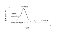
- FIG. 2 is a relationship diagram illustrating the relationship between the position (part) of a material and the size of the maximum principal strain during drawing shown on the right side of FIG. 1. It is a basic diagram which shows the example of the introduction position of the bead part preformed in the product shape shown in FIG. It is a flowchart which shows the process sequence in one Embodiment of the determination method of the preforming shape of this invention.
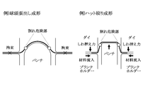
- FIG. 1 cracks occurring in blank B, which is a material made of a steel plate as a flat metal plate, at the shoulder portion of a punch for stretch forming or drawing, are caused by the frictional resistance between the mold and the material, This occurs because the portion of the material located on the top surface of the punch is not distorted (the material outflow from the position of the top surface of the punch is small), and strain is concentrated on the portion of the material located on the shoulder portion of the punch.
- the corner portion has little material inflow from the flange portion P3 and is adjacent to the corner portion. Since the material inflow is large in the flange portion 3 of the portion to be engaged, flange wrinkles are generated due to this inflow difference in the flange portion P3 of the portion adjacent to the corner portion.
- any molding defects such as cracks and flange wrinkles can be avoided by promoting the inflow of the material into a specific part of the material.
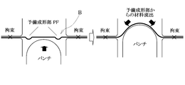
- the state of the material before and after the final forming is used in the stretch forming, and a blank B in which a preform of a concave bead portion (preliminary forming portion) PF is introduced on the side of the punch next to the crack occurrence position is used.
- a preform of a concave bead portion (preliminary forming portion) PF is introduced on the side of the punch next to the crack occurrence position is used.
- the preformed bead portion PF is crushed in the middle of the molding of the product shape, so that the material flows out from the bead portion PF of the material to the strain concentration portion located in the punch shoulder portion, that is, the dispersion of the strain. And formability is improved.
- the material of the bead portion PF is also broken by the same method for cracking of the material generated in the drawing at the portion located on the punch shoulder.
- Introducing preforming improves moldability.
- draw forming by introducing pre-forming of the bead portion PF to the vertical wall portion in addition to the top plate portion located at the top of the punch, the tension from the flange portion side is relieved, which is effective in improving formability. is there.
- FIG. 5 shows the maximum principal strain distribution in the cross-sectional direction of the material in the drawing shown in FIG.
- the position where the preformed portion (bead portion PF) is introduced is appropriately a portion where the maximum principal strain rises (increases). If a preformed part is introduced in a region where the maximum main strain is large (cracking risk part), cracks are likely to occur in the preformed part because the strain generated in the preforming is added to the strain in the final molding.
- the pre-formed part Since the vertical wall has a large amount of strain, the possibility of cracking cannot be denied when the pre-formed part is introduced.Therefore, the pre-formed part is introduced to the top plate part, which is located at the top of the punch and has a smaller strain than the vertical wall part. Is preferred. In addition, if the preformed portion is too far from the rising portion of the maximum main strain, the effect of material outflow from the preformed portion to the crack risk portion is reduced.
- the direction in which the bead-shaped preform is introduced (bead-shaped extending direction) is simply a direction parallel to the extending direction of the cracked portion.
- the overhang amount (elongation amount) L of the preforming is set to an elongation amount L0 or less calculated from the maximum principal strain of the crack portion located at the punch shoulder portion shown in FIG. L0 is obtained by subtracting the line length of the flat plate material before preforming from the line length of the overhanging portion.
- L is defined as 0.1 ⁇ L0 ⁇ L ⁇ 1.0 ⁇ L0.
- L> 1.0 ⁇ L0 the wire length becomes excessive, which causes wrinkles.
- L ⁇ 0.1 ⁇ L0 the material supply from the preformed portion becomes insufficient, and cracks are suppressed. I can't.
- flange wrinkles are likely to occur in a portion where there is a difference in the amount of inflow of material from the flange portion to the vertical wall portion, such as in the vicinity of the corner portion, in the drawing of the L-shaped part.
- it is possible to suppress wrinkles by increasing the wrinkle pressing force it is necessary to further increase the wrinkle pressing force as the material strength increases.
- the wrinkle presser force is increased, the material inflow is reduced, so that cracks occur at the punch shoulder and the like.
- the material inflow at the flange wrinkle generation position is W
- the material inflow at a position where no wrinkle is generated in the vicinity is W0
- the inflow difference is W ⁇ W0. Therefore, it is only necessary to extend the wire length by W ⁇ W0 or less in the preformed portion, and here, the elongation L of the preformed portion is set to 0.1 ⁇ (W ⁇ W0) ⁇ L ⁇ (W ⁇ W0). To do.
- L> (W ⁇ W0) excessive material outflow from the preformed portion occurs, which causes the generation of flange wrinkles.
- the cross-sectional shape of the preformed portion is preferably a curved shape from the viewpoint of easy crushing of the preformed portion, but may be a rectangular cross section or the like as long as the line length can be secured by a predetermined amount. Also, from the viewpoint of reducing the number of processes, in the blanking process in which a material having a predetermined contour shape is punched with a die from a rectangular or strip-shaped material plate before forming the material into a product shape, It is preferable to perform preforming.
- the shape of the preformed portion and the determination of the introduction position may be determined by observing cracks and wrinkles of the product actually press-molded from the flat blank, but the preformed shape of one embodiment of the present invention
- the determination is made by using a computer-executed analysis by a normal FEM (Finite Element Method) program for press-molding a product shape from a blank. This can be done more effectively.
- FEM Finite Element Method
- step S ⁇ b> 1 a blank shape is appropriately set in step S ⁇ b> 1, and in the next step S ⁇ b> 2, FEM forming analysis is performed when a product shape (press-formed part shape) is press-formed from the blank shape, and the following steps In S3, the result of the molding analysis is used to investigate the presence or absence of cracks or wrinkles in the product shape.
- step S4 the presence or absence of cracks or wrinkles is determined from the results of the investigation. If so, in step S5, the shape, height, length, and position of the bead shape to be preformed into the blank are set, and if already set, they are changed, and then the process returns to step S2.
- step S4 it is determined whether cracks or wrinkles are generated from the investigation result. If no cracks or wrinkles are generated, the process ends.
- the bead shape to be preformed and / or the introduction position of the bead shape is changed and the preforming analysis is repeated. Therefore, the bead shape to be preformed during actual press molding and the introduction position of the bead shape are accurately positioned so that cracks and flange wrinkles do not occur when the product shape is pressed from the preformed material shape in the final process. Can be determined.
- the material of the blank was a 1180 MPa grade steel plate with a thickness of 1.6 mm, and the stress-strain relationship obtained by approximating the stress-strain curve obtained from the JIS No. 5 tensile test with the Swift equation was used.
- the friction coefficient between the blank and the mold was set to 0.12.
- Cushion force (wrinkle presser force) is 50 tons and 80 tons.
- FLD forming limit diagram
- Table 1 shows the results of the above determination.
- No. 1 (Comparative Example 1) is a result of general drawing without pre-forming, and cracks occurred at positions corresponding to the punch shoulders, and wrinkles occurred in the flanges.
- No. 2 to No. In No. 4 (Examples 1 to 3), preforming was introduced at a position corresponding to the top of the punch as a countermeasure against cracking. Although the cushioning force was 80 tons as a countermeasure against flange wrinkles, no cracks were found at the position corresponding to the punch shoulder.
- No. No. 5 (Comparative Example 2) had a short preformed wire length, and therefore cracks occurred at positions corresponding to the punch shoulders. No. No.
- the molded part shape may have a curved top plate portion and may be formed by overhanging a spherical head, or may be other shapes such as a U shape or a U shape in addition to an L shape in plan view. .
- the press die is composed of an upper die having a die, a punch cooperating with the upper die, and a lower die having a blank holder for sandwiching a blank between the upper die around the punch.
- the upper die may have a die that positively crushes the bead portion of the blank between the lower die punch, or upside down with those dies. You may have the structure of.
- the preform shape analysis is performed by changing the bead shape to be preformed and / or the introduction position of the bead shape until it is determined that the crack and the flange wrinkle do not occur. Since the process is repeated, the bead shape to be preformed during actual press molding and the introduction position of the bead shape are cracked when the product shape or press molded part shape is pressed from the preformed material shape in the final process. In addition, it is possible to accurately determine the position where the flange wrinkle does not occur.
Landscapes
- Engineering & Computer Science (AREA)
- Mechanical Engineering (AREA)
- Shaping Metal By Deep-Drawing, Or The Like (AREA)
Abstract
Description
天板部と、その天板部に連続して形成された縦壁部と、その縦壁部に連続して形成されたフランジ部と、を有する製品形状を二段階以上のプレス工程で成形するプレス成形方法において、
平板状の金属板である素材を製品形状に成形する際の割れやフランジしわの発生位置の近傍に相当する素材の位置に凸もしくは凹形状のビード形状を予備成形し、
その後、前記ビード形状を予備成形した素材から製品形状をプレス成形することを特徴とするものである。
また、上記知見に基づき前記目的を達成する本発明のプレス成形部品の製造方法は、
天板部と、その天板部に連続して形成された縦壁部と、その縦壁部に連続して形成されたフランジ部と、を有するプレス成形部品形状を二段階以上のプレス工程で成形するプレス成形部品の製造方法において、
平板状の金属板である素材をプレス成形部品形状に成形する際の割れやフランジしわの発生位置の近傍に相当する素材の位置に凸もしくは凹形状のビード形状を予備成形し、
その後、前記ビード形状を予備成形した素材から前記プレス成形部品形状をプレス成形することを特徴とするものである。
平板状の金属板の素材形状から製品形状またはプレス成形部品形状をプレス成形する際の成形解析をFEMで行う当初成形解析工程と、
当初成形解析工程により割れまたはフランジしわが発生することが判明した場合に、その発生位置に基づいて、予備成形するビード形状およびそのビード形状の導入位置を設定する工程と、
ビード形状を予備成形した素材形状から製品形状またはプレス成形部品形状をプレス成形する際の成形解析をFEMで行う予備成形解析工程と、
予備成形解析工程により割れまたはフランジしわが発生することが判明した場合に、その発生位置に基づいて、予備成形するビード形状および/またはそのビード形状の導入位置を変更する工程と、
予備成形解析工程により割れおよびフランジしわが発生しないことが判明した場合に、その予備成形解析の際のビード形状およびそのビード形状の導入位置を、予備成形するビード形状およびそのビード形状の導入位置に決定する工程と、
を具えることを特徴とするものである。
また、本発明のプレス成形部品の製造方法では、天板部と、その天板部に連続して形成された縦壁部と、その縦壁部に連続して形成されたフランジ部と、を有するプレス成形部品形状を二段階以上のプレス工程で成形するプレス成形部品の製造方法において、平板状の金属板である素材をプレス成形部品形状に成形する際の割れやフランジしわの発生位置の近傍に相当する素材の位置に凸もしくは凹形状のビード形状を予備成形し、その後、前記ビード形状を予備成形した素材からプレス成形部品形状をプレス成形する。
それゆえ、ビード形状を予備成形した素材から製品形状またはプレス成形部品形状をプレス成形する際に、平板状素材を製品形状またはプレス成形部品形状に成形する場合に割れやフランジしわが発生する位置付近に、近傍に位置する凸もしくは凹形状のビード形状が潰れることでそこから材料が供給されるので、素材が延びすぎて割れが発生するのを防止できるとともに、フランジ部からの材料流入が多すぎてフランジしわが発生するのを防止できる。従って、複雑な構造の金型やプレス工程の増加や部品形状の制約を伴わずに絞り成形や張出し成形において割れやしわの発生を抑制し、効果的に歩留まりおよび成形性を向上させることができる。
それゆえ、割れおよびフランジしわが発生しないことが判明するまで、予備成形するビード形状および/またはそのビード形状の導入位置を変更して予備成形解析を行うことを繰返すので、実際のプレス成形の際に予備成形するビード形状およびそのビード形状の導入位置を、予備成形した素材形状から最終工程で製品形状またはプレス成形部品形状をプレス成形する際に割れおよびフランジしわが発生しない位置に正確に決定することができる。
上記実施形態の実施例および比較例について以下に説明する。製品形状として図2に示すプレス成形部品PのL字状の部品形状を用いて、図4に示すように、ダイを持つ上型と、上型のダイと共働するパンチおよびその周囲で上型のダイとの間にブランクを挟持するブランクホルダーを持つ下型とから構成されるプレス金型を用いた絞り成形のFEM解析を行った。FEM解析の条件は、ソルバーがLD-DYNAバージョン971(動的陽解法)、メッシュサイズが2mmである。ブランクの材料は1180MPa級鋼板の1.6mm厚とし、JIS5号引張試験から求まる応力-ひずみ曲線をSwiftの式で近似した応力-ひずみ関係を使用した。ブランクと金型との摩擦係数は0.12とした。クッション力(しわ押え力)は50トンおよび80トンとし、解析結果に用いた材料の成形限界線図(FLD)を適用して、図2に示す割れ危険部およびフランジしわ危険部の判定を行った。

P プレス製品(プレス成形部品)
P1 天板部
P2 縦壁部
P3 フランジ部
PF 予備成形部(ビード部)
Claims (11)
- 天板部と、その天板部に連続して形成された縦壁部と、その縦壁部に連続して形成されたフランジ部と、を有する製品形状を二段階以上のプレス工程で成形するプレス成形方法において、
平板状の金属板である素材を製品形状に成形する際の割れやフランジしわの発生位置の近傍に相当する素材の位置に凸もしくは凹形状のビード形状を予備成形し、
その後、前記ビード形状を予備成形した素材から製品形状をプレス成形することを特徴とするプレス成形方法。 - 天板部と、その天板部に連続して形成された縦壁部と、その縦壁部に連続して形成されたフランジ部と、を有するプレス成形部品の形状を二段階以上のプレス工程で成形するプレス成形部品の製造方法において、
平板状の金属板である素材をプレス成形部品形状に成形する際の割れやフランジしわの発生位置の近傍に相当する素材の位置に凸もしくは凹形状のビード形状を予備成形し、
その後、前記ビード形状を予備成形した素材からプレス成形部品形状をプレス成形することを特徴とするプレス成形部品の製造方法。 - 前記割れやフランジしわの発生位置は、FEMにより素材形状から製品形状またはプレス成形部品形状をプレス成形する際の成形解析を行った結果に基づいて判断することを特徴とする請求項1または2記載の方法。
- 前記ビード形状の予備成形は、素材のブランキング工程で行うことを特徴とする請求項1から3までの何れか1項記載の方法。
- 請求項1から4までの何れか1項記載の方法に用いられる予備成形形状の決定方法において、
平板状の金属板の素材形状から製品形状またはプレス成形部品形状をプレス成形する際の成形解析をFEMで行う当初成形解析工程と、
当初成形解析工程により割れまたはフランジしわが発生することが判明した場合に、その発生位置に基づいて、予備成形するビード形状およびそのビード形状の導入位置を設定する工程と、
ビード形状を予備成形した素材形状から製品形状またはプレス成形部品形状をプレス成形する際の成形解析をFEMで行う予備成形解析工程と、
予備成形解析工程により割れまたはフランジしわが発生することが判明した場合に、その発生位置に基づいて、予備成形するビード形状および/またはそのビード形状の導入位置を変更する工程と、
予備成形解析工程により割れおよびフランジしわが発生しないことが判明した場合に、その予備成形解析の際のビード形状およびそのビード形状の導入位置を、予備成形するビード形状およびそのビード形状の導入位置に決定する工程と、
を具えることを特徴とする予備成形形状の決定方法。 - 割れ部の延在方向と平行に延在するようにビード形状を設定することを特徴とする請求項5記載の予備成形形状の決定方法。
- 割れ部の最大主ひずみ方向を求め、その最大主ひずみ方向と直交する方向に延在するようにビード形状を設定することを特徴とする請求項5記載の予備成形形状の決定方法。
- 割れ部においてその割れ部の延在方向と直交する方向の断面の最大主ひずみ分布を求め、ひずみの立ち上り位置を予備成形位置に設定することを特徴とする請求項5から7までの何れか1項記載の予備成形形状の決定方法。
- 割れ部においてその割れ部の延在方向と直交する方向の断面形状から割れ部の素材伸び量L0を求め、予備成形するビード形状の断面形状から求まるビード部の素材伸び量Lが0.1×L0≦L≦1.0×L0となる断面を有するビード形状を設定することを特徴とする請求項5から8までの何れか1項記載の予備成形形状の決定方法。
- フランジしわ発生位置の近傍の縦壁に相当する素材の位置にフランジ部の延在方向と平行な方向に延在するビード形状を設定することを特徴とする請求項5から9までの何れか1項記載の予備成形形状の決定方法。
- フランジしわ発生位置からの材料流入量Wとフランジしわ発生位置に隣接するしわ発生のないフランジ部からの材料流入量W0との差W-W0を求め、予備成形するビード形状の断面形状から求まるビード部の素材伸び量Lが0.1×(W-W0)≦L≦(W-W0)となる断面を有するビード形状を設定することを特徴とする請求項5から10までの何れか1項記載の予備成形形状の決定方法。
Priority Applications (6)
| Application Number | Priority Date | Filing Date | Title |
|---|---|---|---|
| EP15743732.8A EP3100797B1 (en) | 2014-01-28 | 2015-01-26 | Press forming method, method for manufacturing press-formed component and method for determining preform shape used in these methods |
| MX2016009660A MX380573B (es) | 2014-01-28 | 2015-01-26 | Método de estampación, método para la fabricación de un componente estampado y método para la determinación de una forma de preforma utilizada en estos métodos. |
| KR1020167019549A KR101853573B1 (ko) | 2014-01-28 | 2015-01-26 | 프레스 성형 방법과 그 방법에 이용되는 예비 성형 형상의 결정 방법 |
| JP2015559922A JP6191846B2 (ja) | 2014-01-28 | 2015-01-26 | プレス成形方法およびプレス成形部品の製造方法並びにそれらの方法に用いられる予備成形形状の決定方法 |
| CN201580006217.6A CN105960295B (zh) | 2014-01-28 | 2015-01-26 | 冲压成型方法、冲压成型部件的制造方法以及在这些方法中使用的预成型形状的确定方法 |
| US15/114,534 US10639695B2 (en) | 2014-01-28 | 2015-01-26 | Press forming method, method for manufacturing press-formed component and method for determining preform shape used in these methods |
Applications Claiming Priority (2)
| Application Number | Priority Date | Filing Date | Title |
|---|---|---|---|
| JP2014-012949 | 2014-01-28 | ||
| JP2014012949 | 2014-01-28 |
Publications (1)
| Publication Number | Publication Date |
|---|---|
| WO2015115348A1 true WO2015115348A1 (ja) | 2015-08-06 |
Family
ID=53756922
Family Applications (1)
| Application Number | Title | Priority Date | Filing Date |
|---|---|---|---|
| PCT/JP2015/051958 Ceased WO2015115348A1 (ja) | 2014-01-28 | 2015-01-26 | プレス成形方法およびプレス成形部品の製造方法並びにそれらの方法に用いられる予備成形形状の決定方法 |
Country Status (7)
| Country | Link |
|---|---|
| US (1) | US10639695B2 (ja) |
| EP (1) | EP3100797B1 (ja) |
| JP (1) | JP6191846B2 (ja) |
| KR (1) | KR101853573B1 (ja) |
| CN (1) | CN105960295B (ja) |
| MX (1) | MX380573B (ja) |
| WO (1) | WO2015115348A1 (ja) |
Cited By (6)
| Publication number | Priority date | Publication date | Assignee | Title |
|---|---|---|---|---|
| WO2018123989A1 (ja) * | 2016-12-26 | 2018-07-05 | 新日鐵住金株式会社 | 金属板の成形方法、中間形状の設計方法、金属板の成形用金型、コンピュータプログラム、及び記録媒体 |
| WO2020121591A1 (ja) | 2018-12-12 | 2020-06-18 | Jfeスチール株式会社 | プレス成形方法 |
| CN113828690A (zh) * | 2021-08-23 | 2021-12-24 | 中国第一汽车股份有限公司 | 一种汽车顶盖尾部区域尺寸控制方法 |
| JP7020599B1 (ja) * | 2020-09-02 | 2022-02-16 | Jfeスチール株式会社 | プレス部品の製造方法、金型の設計方法、金型形状設計装置、及び金型 |
| JP2022150889A (ja) * | 2021-03-26 | 2022-10-07 | ダイハツ工業株式会社 | プレス成形方法 |
| WO2024019168A1 (ja) | 2022-07-22 | 2024-01-25 | Jfeスチール株式会社 | プレス成形品の製造方法 |
Families Citing this family (12)
| Publication number | Priority date | Publication date | Assignee | Title |
|---|---|---|---|---|
| WO2017006793A1 (ja) * | 2015-07-06 | 2017-01-12 | 新日鐵住金株式会社 | プレス部品の製造方法および製造装置 |
| CN106391815A (zh) * | 2016-11-03 | 2017-02-15 | 南京航空航天大学 | 一种改善冲压拉深件壁厚均匀性的装置及方法 |
| DE102016125671A1 (de) * | 2016-12-23 | 2018-06-28 | Thyssenkrupp Ag | Verfahren und Vorrichtung zur Herstellung von Blechbauteilen |
| CN107570586B (zh) * | 2017-09-07 | 2019-04-16 | 安徽江淮汽车集团股份有限公司 | 一种解决弧形等高翻边开裂的工艺方法及模具结构 |
| CN107766693B (zh) * | 2017-09-30 | 2020-05-29 | 上海思致汽车工程技术有限公司 | 一种用于冲压的流经拉延筋的板料的开裂评判方法 |
| JP2020146747A (ja) * | 2019-03-15 | 2020-09-17 | 本田技研工業株式会社 | 車体フレームの製造方法、及び車体フレーム |
| CN112676416B (zh) * | 2019-10-17 | 2023-05-05 | 本田技研工业株式会社 | 车身骨架构件的制造方法 |
| US12194523B2 (en) | 2020-03-09 | 2025-01-14 | Jfe Steel Corporation | Method for manufacturing pressed component, metal sheet for press forming, and high-tensile steel sheet |
| JP6919742B1 (ja) * | 2020-04-07 | 2021-08-18 | Jfeスチール株式会社 | 金属板のくびれ限界ひずみ特定方法 |
| CN113849919A (zh) * | 2020-06-26 | 2021-12-28 | 汽车成型工程有限公司 | 用于分析制造工序的模拟结果的方法 |
| CN111940605B (zh) * | 2020-08-04 | 2022-09-23 | 惠州融汇科技有限公司 | 新能源汽车电池箱体顶盖成型结构 |
| WO2024006051A1 (en) | 2022-06-30 | 2024-01-04 | Cleveland-Cliffs Steel Properties Inc. | Method for prevention of premature edge fracture at draw bead |
Citations (10)
| Publication number | Priority date | Publication date | Assignee | Title |
|---|---|---|---|---|
| JPH0929349A (ja) | 1995-07-18 | 1997-02-04 | Toyota Motor Corp | 可変ビードを利用した絞り成形方法および装置 |
| JP2006272413A (ja) * | 2005-03-30 | 2006-10-12 | Kobe Steel Ltd | 湾曲状チャンネル部材の成形方法 |
| US20090255317A1 (en) * | 2008-04-11 | 2009-10-15 | Thyssenkrupp Steel Ag | Method for the production of high-precision half shells with high dimensional precision |
| WO2011126058A1 (ja) * | 2010-04-07 | 2011-10-13 | 新日本製鐵株式会社 | 破断判定方法、破断判定装置、プログラムおよびコンピュータ読み取り可能な記録媒体 |
| JP2011218389A (ja) * | 2010-04-07 | 2011-11-04 | Nippon Steel Corp | ブランク材破損検知センサ設置位置評価方法 |
| JP2011235356A (ja) | 2010-04-13 | 2011-11-24 | Nippon Steel Corp | プレス成形金型及びプレス成形方法 |
| WO2012070623A1 (ja) | 2010-11-24 | 2012-05-31 | 新日本製鐵株式会社 | L形製品の製造方法 |
| US20120234070A1 (en) * | 2011-03-14 | 2012-09-20 | Ford Global Technologies, Llc | Method of Drawing a Blank by Preforming a Channel in a Preform that is Subsequently Drawn into a Die Cavity |
| WO2012161050A1 (ja) * | 2011-05-20 | 2012-11-29 | 新日鐵住金株式会社 | プレス成形方法及び車体部品 |
| JP2013169578A (ja) * | 2012-02-22 | 2013-09-02 | Topre Corp | プレス部品の成形方法 |
Family Cites Families (7)
| Publication number | Priority date | Publication date | Assignee | Title |
|---|---|---|---|---|
| US6353768B1 (en) * | 1998-02-02 | 2002-03-05 | General Electric Company | Method and apparatus for designing a manufacturing process for sheet metal parts |
| JP2001076022A (ja) * | 1999-09-03 | 2001-03-23 | Kobe Steel Ltd | アルミニウム合金板からなる成形品の設計方法 |
| CN100574919C (zh) * | 2006-12-27 | 2009-12-30 | 比亚迪股份有限公司 | 一种消除具有凹陷区域的板状制件局部褶皱的方法 |
| JP5695381B2 (ja) | 2010-09-30 | 2015-04-01 | 株式会社神戸製鋼所 | プレス成形品の製造方法 |
| JP5765013B2 (ja) * | 2011-03-30 | 2015-08-19 | Jfeスチール株式会社 | 多工程プレス成形におけるスプリングバック要因分析方法 |
| US9279167B2 (en) * | 2011-07-20 | 2016-03-08 | GM Global Technology Operations LLC | Method of forming a stamped article |
| JP5794025B2 (ja) | 2011-07-29 | 2015-10-14 | Jfeスチール株式会社 | 金型設計方法及びプレス成形方法 |
-
2015
- 2015-01-26 US US15/114,534 patent/US10639695B2/en not_active Expired - Fee Related
- 2015-01-26 CN CN201580006217.6A patent/CN105960295B/zh not_active Expired - Fee Related
- 2015-01-26 EP EP15743732.8A patent/EP3100797B1/en active Active
- 2015-01-26 WO PCT/JP2015/051958 patent/WO2015115348A1/ja not_active Ceased
- 2015-01-26 JP JP2015559922A patent/JP6191846B2/ja active Active
- 2015-01-26 MX MX2016009660A patent/MX380573B/es unknown
- 2015-01-26 KR KR1020167019549A patent/KR101853573B1/ko not_active Expired - Fee Related
Patent Citations (10)
| Publication number | Priority date | Publication date | Assignee | Title |
|---|---|---|---|---|
| JPH0929349A (ja) | 1995-07-18 | 1997-02-04 | Toyota Motor Corp | 可変ビードを利用した絞り成形方法および装置 |
| JP2006272413A (ja) * | 2005-03-30 | 2006-10-12 | Kobe Steel Ltd | 湾曲状チャンネル部材の成形方法 |
| US20090255317A1 (en) * | 2008-04-11 | 2009-10-15 | Thyssenkrupp Steel Ag | Method for the production of high-precision half shells with high dimensional precision |
| WO2011126058A1 (ja) * | 2010-04-07 | 2011-10-13 | 新日本製鐵株式会社 | 破断判定方法、破断判定装置、プログラムおよびコンピュータ読み取り可能な記録媒体 |
| JP2011218389A (ja) * | 2010-04-07 | 2011-11-04 | Nippon Steel Corp | ブランク材破損検知センサ設置位置評価方法 |
| JP2011235356A (ja) | 2010-04-13 | 2011-11-24 | Nippon Steel Corp | プレス成形金型及びプレス成形方法 |
| WO2012070623A1 (ja) | 2010-11-24 | 2012-05-31 | 新日本製鐵株式会社 | L形製品の製造方法 |
| US20120234070A1 (en) * | 2011-03-14 | 2012-09-20 | Ford Global Technologies, Llc | Method of Drawing a Blank by Preforming a Channel in a Preform that is Subsequently Drawn into a Die Cavity |
| WO2012161050A1 (ja) * | 2011-05-20 | 2012-11-29 | 新日鐵住金株式会社 | プレス成形方法及び車体部品 |
| JP2013169578A (ja) * | 2012-02-22 | 2013-09-02 | Topre Corp | プレス部品の成形方法 |
Non-Patent Citations (1)
| Title |
|---|
| See also references of EP3100797A4 |
Cited By (11)
| Publication number | Priority date | Publication date | Assignee | Title |
|---|---|---|---|---|
| WO2018123989A1 (ja) * | 2016-12-26 | 2018-07-05 | 新日鐵住金株式会社 | 金属板の成形方法、中間形状の設計方法、金属板の成形用金型、コンピュータプログラム、及び記録媒体 |
| JPWO2018123989A1 (ja) * | 2016-12-26 | 2019-11-07 | 日本製鉄株式会社 | 金属板の成形方法、中間形状の設計方法、金属板の成形用金型、コンピュータプログラム、及び記録媒体 |
| US11270047B2 (en) | 2016-12-26 | 2022-03-08 | Nippon Steel Corporation | Metal sheet forming method, intermediate shape design method, metal sheet forming die, computer program, and recording medium |
| WO2020121591A1 (ja) | 2018-12-12 | 2020-06-18 | Jfeスチール株式会社 | プレス成形方法 |
| JP2020093276A (ja) * | 2018-12-12 | 2020-06-18 | Jfeスチール株式会社 | プレス成形方法 |
| KR20210089738A (ko) | 2018-12-12 | 2021-07-16 | 제이에프이 스틸 가부시키가이샤 | 프레스 성형 방법 |
| JP7020599B1 (ja) * | 2020-09-02 | 2022-02-16 | Jfeスチール株式会社 | プレス部品の製造方法、金型の設計方法、金型形状設計装置、及び金型 |
| JP2022150889A (ja) * | 2021-03-26 | 2022-10-07 | ダイハツ工業株式会社 | プレス成形方法 |
| JP7610908B2 (ja) | 2021-03-26 | 2025-01-09 | ダイハツ工業株式会社 | プレス成形方法 |
| CN113828690A (zh) * | 2021-08-23 | 2021-12-24 | 中国第一汽车股份有限公司 | 一种汽车顶盖尾部区域尺寸控制方法 |
| WO2024019168A1 (ja) | 2022-07-22 | 2024-01-25 | Jfeスチール株式会社 | プレス成形品の製造方法 |
Also Published As
| Publication number | Publication date |
|---|---|
| JPWO2015115348A1 (ja) | 2017-03-23 |
| US20160354825A1 (en) | 2016-12-08 |
| CN105960295A (zh) | 2016-09-21 |
| EP3100797A4 (en) | 2017-03-08 |
| KR20160101126A (ko) | 2016-08-24 |
| CN105960295B (zh) | 2018-04-24 |
| EP3100797A1 (en) | 2016-12-07 |
| MX2016009660A (es) | 2017-03-10 |
| JP6191846B2 (ja) | 2017-09-06 |
| US10639695B2 (en) | 2020-05-05 |
| MX380573B (es) | 2025-03-11 |
| EP3100797B1 (en) | 2021-06-16 |
| KR101853573B1 (ko) | 2018-04-30 |
Similar Documents
| Publication | Publication Date | Title |
|---|---|---|
| JP6191846B2 (ja) | プレス成形方法およびプレス成形部品の製造方法並びにそれらの方法に用いられる予備成形形状の決定方法 | |
| JP6028956B1 (ja) | プレス成形方法およびそのプレス成形方法を用いた部品の製造方法並びにそのプレス成形方法を用いて製造された部品 | |
| KR101958584B1 (ko) | 프레스 성형품의 제조 방법, 제조 장치 및 제조 설비열 | |
| CN109562427B (zh) | 冲压成型品的制造方法 | |
| RU2692353C1 (ru) | Способ производства штампованных изделий и производственная линия для них | |
| CN107708884B (zh) | 拉伸凸缘成型部件的制造方法 | |
| KR20170080681A (ko) | 프레스 성형품의 제조 방법 및 제조 장치 | |
| JP6354955B2 (ja) | ハット形断面形状を有するプレス成形品の製造方法 | |
| JP6665837B2 (ja) | プレス成形品の製造方法 | |
| KR102862571B1 (ko) | 프레스 성형 방법 | |
| CN107921504B (zh) | 拉伸凸缘成形零件的制造方法 | |
| CN115210013A (zh) | 冲压部件的制造方法、冲压成型用的金属板及高张力钢板 | |
| KR20180102607A (ko) | 프레스 성형품의 제조 방법 | |
| JP7396415B1 (ja) | プレス成形品の製造方法 | |
| JP7396550B1 (ja) | プレス成形方法及びプレス成形品の製造方法 | |
| JP6908078B2 (ja) | プレス部品の製造方法及び下金型の設計方法 | |
| JP5979164B2 (ja) | プレス成形方法 | |
| CN108778549A (zh) | 构造体及其制造方法 | |
| JP2022013343A (ja) | プレス部品の製造方法及びプレス成形用の金属板 | |
| JP6176429B1 (ja) | プレス成形品の製造方法 | |
| JP2021159951A (ja) | 板金成形品の製造方法、板金成形品の製造装置、及びフランジアップ工具 | |
| WO2021241024A1 (ja) | プレス成形方法 | |
| JP2021159946A (ja) | 板金成形品製造方法、板金成形品の製造装置及びフランジアップ用工具 |
Legal Events
| Date | Code | Title | Description |
|---|---|---|---|
| 121 | Ep: the epo has been informed by wipo that ep was designated in this application |
Ref document number: 15743732 Country of ref document: EP Kind code of ref document: A1 |
|
| ENP | Entry into the national phase |
Ref document number: 2015559922 Country of ref document: JP Kind code of ref document: A |
|
| REEP | Request for entry into the european phase |
Ref document number: 2015743732 Country of ref document: EP |
|
| WWE | Wipo information: entry into national phase |
Ref document number: 2015743732 Country of ref document: EP |
|
| ENP | Entry into the national phase |
Ref document number: 20167019549 Country of ref document: KR Kind code of ref document: A |
|
| WWE | Wipo information: entry into national phase |
Ref document number: MX/A/2016/009660 Country of ref document: MX |
|
| WWE | Wipo information: entry into national phase |
Ref document number: 15114534 Country of ref document: US |
|
| NENP | Non-entry into the national phase |
Ref country code: DE |
|
| WWE | Wipo information: entry into national phase |
Ref document number: IDP00201605033 Country of ref document: ID |