WO2015111158A1 - 表示装置 - Google Patents
表示装置 Download PDFInfo
- Publication number
- WO2015111158A1 WO2015111158A1 PCT/JP2014/051288 JP2014051288W WO2015111158A1 WO 2015111158 A1 WO2015111158 A1 WO 2015111158A1 JP 2014051288 W JP2014051288 W JP 2014051288W WO 2015111158 A1 WO2015111158 A1 WO 2015111158A1
- Authority
- WO
- WIPO (PCT)
- Prior art keywords
- display
- image
- control unit
- unit
- display device
- Prior art date
- Legal status (The legal status is an assumption and is not a legal conclusion. Google has not performed a legal analysis and makes no representation as to the accuracy of the status listed.)
- Ceased
Links
Images












Classifications
-
- G—PHYSICS
- G06—COMPUTING OR CALCULATING; COUNTING
- G06F—ELECTRIC DIGITAL DATA PROCESSING
- G06F3/00—Input arrangements for transferring data to be processed into a form capable of being handled by the computer; Output arrangements for transferring data from processing unit to output unit, e.g. interface arrangements
- G06F3/01—Input arrangements or combined input and output arrangements for interaction between user and computer
- G06F3/03—Arrangements for converting the position or the displacement of a member into a coded form
-
- G—PHYSICS
- G09—EDUCATION; CRYPTOGRAPHY; DISPLAY; ADVERTISING; SEALS
- G09G—ARRANGEMENTS OR CIRCUITS FOR CONTROL OF INDICATING DEVICES USING STATIC MEANS TO PRESENT VARIABLE INFORMATION
- G09G3/00—Control arrangements or circuits, of interest only in connection with visual indicators other than cathode-ray tubes
- G09G3/20—Control arrangements or circuits, of interest only in connection with visual indicators other than cathode-ray tubes for presentation of an assembly of a number of characters, e.g. a page, by composing the assembly by combination of individual elements arranged in a matrix no fixed position being assigned to or needed to be assigned to the individual characters or partial characters
- G09G3/34—Control arrangements or circuits, of interest only in connection with visual indicators other than cathode-ray tubes for presentation of an assembly of a number of characters, e.g. a page, by composing the assembly by combination of individual elements arranged in a matrix no fixed position being assigned to or needed to be assigned to the individual characters or partial characters by control of light from an independent source
- G09G3/3406—Control of illumination source
-
- G—PHYSICS
- G06—COMPUTING OR CALCULATING; COUNTING
- G06F—ELECTRIC DIGITAL DATA PROCESSING
- G06F3/00—Input arrangements for transferring data to be processed into a form capable of being handled by the computer; Output arrangements for transferring data from processing unit to output unit, e.g. interface arrangements
- G06F3/01—Input arrangements or combined input and output arrangements for interaction between user and computer
- G06F3/03—Arrangements for converting the position or the displacement of a member into a coded form
- G06F3/041—Digitisers, e.g. for touch screens or touch pads, characterised by the transducing means
- G06F3/042—Digitisers, e.g. for touch screens or touch pads, characterised by the transducing means by opto-electronic means
-
- G—PHYSICS
- G09—EDUCATION; CRYPTOGRAPHY; DISPLAY; ADVERTISING; SEALS
- G09G—ARRANGEMENTS OR CIRCUITS FOR CONTROL OF INDICATING DEVICES USING STATIC MEANS TO PRESENT VARIABLE INFORMATION
- G09G3/00—Control arrangements or circuits, of interest only in connection with visual indicators other than cathode-ray tubes
- G09G3/20—Control arrangements or circuits, of interest only in connection with visual indicators other than cathode-ray tubes for presentation of an assembly of a number of characters, e.g. a page, by composing the assembly by combination of individual elements arranged in a matrix no fixed position being assigned to or needed to be assigned to the individual characters or partial characters
- G09G3/22—Control arrangements or circuits, of interest only in connection with visual indicators other than cathode-ray tubes for presentation of an assembly of a number of characters, e.g. a page, by composing the assembly by combination of individual elements arranged in a matrix no fixed position being assigned to or needed to be assigned to the individual characters or partial characters using controlled light sources
- G09G3/30—Control arrangements or circuits, of interest only in connection with visual indicators other than cathode-ray tubes for presentation of an assembly of a number of characters, e.g. a page, by composing the assembly by combination of individual elements arranged in a matrix no fixed position being assigned to or needed to be assigned to the individual characters or partial characters using controlled light sources using electroluminescent panels
- G09G3/32—Control arrangements or circuits, of interest only in connection with visual indicators other than cathode-ray tubes for presentation of an assembly of a number of characters, e.g. a page, by composing the assembly by combination of individual elements arranged in a matrix no fixed position being assigned to or needed to be assigned to the individual characters or partial characters using controlled light sources using electroluminescent panels semiconductive, e.g. using light-emitting diodes [LED]
-
- G—PHYSICS
- G09—EDUCATION; CRYPTOGRAPHY; DISPLAY; ADVERTISING; SEALS
- G09G—ARRANGEMENTS OR CIRCUITS FOR CONTROL OF INDICATING DEVICES USING STATIC MEANS TO PRESENT VARIABLE INFORMATION
- G09G3/00—Control arrangements or circuits, of interest only in connection with visual indicators other than cathode-ray tubes
- G09G3/20—Control arrangements or circuits, of interest only in connection with visual indicators other than cathode-ray tubes for presentation of an assembly of a number of characters, e.g. a page, by composing the assembly by combination of individual elements arranged in a matrix no fixed position being assigned to or needed to be assigned to the individual characters or partial characters
- G09G3/22—Control arrangements or circuits, of interest only in connection with visual indicators other than cathode-ray tubes for presentation of an assembly of a number of characters, e.g. a page, by composing the assembly by combination of individual elements arranged in a matrix no fixed position being assigned to or needed to be assigned to the individual characters or partial characters using controlled light sources
- G09G3/30—Control arrangements or circuits, of interest only in connection with visual indicators other than cathode-ray tubes for presentation of an assembly of a number of characters, e.g. a page, by composing the assembly by combination of individual elements arranged in a matrix no fixed position being assigned to or needed to be assigned to the individual characters or partial characters using controlled light sources using electroluminescent panels
- G09G3/32—Control arrangements or circuits, of interest only in connection with visual indicators other than cathode-ray tubes for presentation of an assembly of a number of characters, e.g. a page, by composing the assembly by combination of individual elements arranged in a matrix no fixed position being assigned to or needed to be assigned to the individual characters or partial characters using controlled light sources using electroluminescent panels semiconductive, e.g. using light-emitting diodes [LED]
- G09G3/3208—Control arrangements or circuits, of interest only in connection with visual indicators other than cathode-ray tubes for presentation of an assembly of a number of characters, e.g. a page, by composing the assembly by combination of individual elements arranged in a matrix no fixed position being assigned to or needed to be assigned to the individual characters or partial characters using controlled light sources using electroluminescent panels semiconductive, e.g. using light-emitting diodes [LED] organic, e.g. using organic light-emitting diodes [OLED]
- G09G3/3225—Control arrangements or circuits, of interest only in connection with visual indicators other than cathode-ray tubes for presentation of an assembly of a number of characters, e.g. a page, by composing the assembly by combination of individual elements arranged in a matrix no fixed position being assigned to or needed to be assigned to the individual characters or partial characters using controlled light sources using electroluminescent panels semiconductive, e.g. using light-emitting diodes [LED] organic, e.g. using organic light-emitting diodes [OLED] using an active matrix
-
- G—PHYSICS
- G09—EDUCATION; CRYPTOGRAPHY; DISPLAY; ADVERTISING; SEALS
- G09G—ARRANGEMENTS OR CIRCUITS FOR CONTROL OF INDICATING DEVICES USING STATIC MEANS TO PRESENT VARIABLE INFORMATION
- G09G3/00—Control arrangements or circuits, of interest only in connection with visual indicators other than cathode-ray tubes
- G09G3/20—Control arrangements or circuits, of interest only in connection with visual indicators other than cathode-ray tubes for presentation of an assembly of a number of characters, e.g. a page, by composing the assembly by combination of individual elements arranged in a matrix no fixed position being assigned to or needed to be assigned to the individual characters or partial characters
- G09G3/34—Control arrangements or circuits, of interest only in connection with visual indicators other than cathode-ray tubes for presentation of an assembly of a number of characters, e.g. a page, by composing the assembly by combination of individual elements arranged in a matrix no fixed position being assigned to or needed to be assigned to the individual characters or partial characters by control of light from an independent source
-
- G—PHYSICS
- G09—EDUCATION; CRYPTOGRAPHY; DISPLAY; ADVERTISING; SEALS
- G09G—ARRANGEMENTS OR CIRCUITS FOR CONTROL OF INDICATING DEVICES USING STATIC MEANS TO PRESENT VARIABLE INFORMATION
- G09G3/00—Control arrangements or circuits, of interest only in connection with visual indicators other than cathode-ray tubes
- G09G3/20—Control arrangements or circuits, of interest only in connection with visual indicators other than cathode-ray tubes for presentation of an assembly of a number of characters, e.g. a page, by composing the assembly by combination of individual elements arranged in a matrix no fixed position being assigned to or needed to be assigned to the individual characters or partial characters
- G09G3/34—Control arrangements or circuits, of interest only in connection with visual indicators other than cathode-ray tubes for presentation of an assembly of a number of characters, e.g. a page, by composing the assembly by combination of individual elements arranged in a matrix no fixed position being assigned to or needed to be assigned to the individual characters or partial characters by control of light from an independent source
- G09G3/3406—Control of illumination source
- G09G3/3413—Details of control of colour illumination sources
-
- G—PHYSICS
- G09—EDUCATION; CRYPTOGRAPHY; DISPLAY; ADVERTISING; SEALS
- G09G—ARRANGEMENTS OR CIRCUITS FOR CONTROL OF INDICATING DEVICES USING STATIC MEANS TO PRESENT VARIABLE INFORMATION
- G09G3/00—Control arrangements or circuits, of interest only in connection with visual indicators other than cathode-ray tubes
- G09G3/20—Control arrangements or circuits, of interest only in connection with visual indicators other than cathode-ray tubes for presentation of an assembly of a number of characters, e.g. a page, by composing the assembly by combination of individual elements arranged in a matrix no fixed position being assigned to or needed to be assigned to the individual characters or partial characters
- G09G3/34—Control arrangements or circuits, of interest only in connection with visual indicators other than cathode-ray tubes for presentation of an assembly of a number of characters, e.g. a page, by composing the assembly by combination of individual elements arranged in a matrix no fixed position being assigned to or needed to be assigned to the individual characters or partial characters by control of light from an independent source
- G09G3/3406—Control of illumination source
- G09G3/342—Control of illumination source using several illumination sources separately controlled corresponding to different display panel areas, e.g. along one dimension such as lines
-
- G—PHYSICS
- G09—EDUCATION; CRYPTOGRAPHY; DISPLAY; ADVERTISING; SEALS
- G09G—ARRANGEMENTS OR CIRCUITS FOR CONTROL OF INDICATING DEVICES USING STATIC MEANS TO PRESENT VARIABLE INFORMATION
- G09G3/00—Control arrangements or circuits, of interest only in connection with visual indicators other than cathode-ray tubes
- G09G3/20—Control arrangements or circuits, of interest only in connection with visual indicators other than cathode-ray tubes for presentation of an assembly of a number of characters, e.g. a page, by composing the assembly by combination of individual elements arranged in a matrix no fixed position being assigned to or needed to be assigned to the individual characters or partial characters
- G09G3/34—Control arrangements or circuits, of interest only in connection with visual indicators other than cathode-ray tubes for presentation of an assembly of a number of characters, e.g. a page, by composing the assembly by combination of individual elements arranged in a matrix no fixed position being assigned to or needed to be assigned to the individual characters or partial characters by control of light from an independent source
- G09G3/36—Control arrangements or circuits, of interest only in connection with visual indicators other than cathode-ray tubes for presentation of an assembly of a number of characters, e.g. a page, by composing the assembly by combination of individual elements arranged in a matrix no fixed position being assigned to or needed to be assigned to the individual characters or partial characters by control of light from an independent source using liquid crystals
-
- G—PHYSICS
- G09—EDUCATION; CRYPTOGRAPHY; DISPLAY; ADVERTISING; SEALS
- G09G—ARRANGEMENTS OR CIRCUITS FOR CONTROL OF INDICATING DEVICES USING STATIC MEANS TO PRESENT VARIABLE INFORMATION
- G09G5/00—Control arrangements or circuits for visual indicators common to cathode-ray tube indicators and other visual indicators
-
- G—PHYSICS
- G06—COMPUTING OR CALCULATING; COUNTING
- G06F—ELECTRIC DIGITAL DATA PROCESSING
- G06F2203/00—Indexing scheme relating to G06F3/00 - G06F3/048
- G06F2203/041—Indexing scheme relating to G06F3/041 - G06F3/045
- G06F2203/04101—2.5D-digitiser, i.e. digitiser detecting the X/Y position of the input means, finger or stylus, also when it does not touch, but is proximate to the digitiser's interaction surface and also measures the distance of the input means within a short range in the Z direction, possibly with a separate measurement setup
-
- G—PHYSICS
- G09—EDUCATION; CRYPTOGRAPHY; DISPLAY; ADVERTISING; SEALS
- G09G—ARRANGEMENTS OR CIRCUITS FOR CONTROL OF INDICATING DEVICES USING STATIC MEANS TO PRESENT VARIABLE INFORMATION
- G09G2320/00—Control of display operating conditions
- G09G2320/08—Arrangements within a display terminal for setting, manually or automatically, display parameters of the display terminal
-
- G—PHYSICS
- G09—EDUCATION; CRYPTOGRAPHY; DISPLAY; ADVERTISING; SEALS
- G09G—ARRANGEMENTS OR CIRCUITS FOR CONTROL OF INDICATING DEVICES USING STATIC MEANS TO PRESENT VARIABLE INFORMATION
- G09G2330/00—Aspects of power supply; Aspects of display protection and defect management
- G09G2330/02—Details of power systems and of start or stop of display operation
- G09G2330/021—Power management, e.g. power saving
- G09G2330/022—Power management, e.g. power saving in absence of operation, e.g. no data being entered during a predetermined time
-
- G—PHYSICS
- G09—EDUCATION; CRYPTOGRAPHY; DISPLAY; ADVERTISING; SEALS
- G09G—ARRANGEMENTS OR CIRCUITS FOR CONTROL OF INDICATING DEVICES USING STATIC MEANS TO PRESENT VARIABLE INFORMATION
- G09G2354/00—Aspects of interface with display user
-
- G—PHYSICS
- G09—EDUCATION; CRYPTOGRAPHY; DISPLAY; ADVERTISING; SEALS
- G09G—ARRANGEMENTS OR CIRCUITS FOR CONTROL OF INDICATING DEVICES USING STATIC MEANS TO PRESENT VARIABLE INFORMATION
- G09G2360/00—Aspects of the architecture of display systems
- G09G2360/14—Detecting light within display terminals, e.g. using a single or a plurality of photosensors
- G09G2360/144—Detecting light within display terminals, e.g. using a single or a plurality of photosensors the light being ambient light
-
- G—PHYSICS
- G09—EDUCATION; CRYPTOGRAPHY; DISPLAY; ADVERTISING; SEALS
- G09G—ARRANGEMENTS OR CIRCUITS FOR CONTROL OF INDICATING DEVICES USING STATIC MEANS TO PRESENT VARIABLE INFORMATION
- G09G2360/00—Aspects of the architecture of display systems
- G09G2360/14—Detecting light within display terminals, e.g. using a single or a plurality of photosensors
- G09G2360/145—Detecting light within display terminals, e.g. using a single or a plurality of photosensors the light originating from the display screen
- G09G2360/147—Detecting light within display terminals, e.g. using a single or a plurality of photosensors the light originating from the display screen the originated light output being determined for each pixel
-
- G—PHYSICS
- G09—EDUCATION; CRYPTOGRAPHY; DISPLAY; ADVERTISING; SEALS
- G09G—ARRANGEMENTS OR CIRCUITS FOR CONTROL OF INDICATING DEVICES USING STATIC MEANS TO PRESENT VARIABLE INFORMATION
- G09G2360/00—Aspects of the architecture of display systems
- G09G2360/14—Detecting light within display terminals, e.g. using a single or a plurality of photosensors
- G09G2360/145—Detecting light within display terminals, e.g. using a single or a plurality of photosensors the light originating from the display screen
- G09G2360/147—Detecting light within display terminals, e.g. using a single or a plurality of photosensors the light originating from the display screen the originated light output being determined for each pixel
- G09G2360/148—Detecting light within display terminals, e.g. using a single or a plurality of photosensors the light originating from the display screen the originated light output being determined for each pixel the light being detected by light detection means within each pixel
-
- G—PHYSICS
- G09—EDUCATION; CRYPTOGRAPHY; DISPLAY; ADVERTISING; SEALS
- G09G—ARRANGEMENTS OR CIRCUITS FOR CONTROL OF INDICATING DEVICES USING STATIC MEANS TO PRESENT VARIABLE INFORMATION
- G09G2380/00—Specific applications
- G09G2380/14—Electronic books and readers
Definitions
- the present invention relates to display control in a display device having a pixel region composed of a plurality of pixels, and more particularly to a display device capable of appropriately controlling display contents when there is a shielding object that shields the pixel region.
- Patent Document 1 discloses an invention in which when the grip on the display unit of the device is detected, the display region is changed within the pixel region so as to exclude the gripped portion.
- a tablet PC Personal Computer
- a tablet PC uses a wide range within a wide surface of a flat housing as a display surface.
- sheet-like PCs using flexible display panels may become widespread. It is possible to apply the change of the display area in the pixel area as in Patent Document 1 in a device that is becoming thinner. Further, in a device having a display portion to be thinned, as disclosed in Patent Documents 2 to 4, it is possible to perform display control so as to avoid a decrease in visibility due to strong ambient light reflection. .
- a device having a display unit that is becoming thinner may be handled like a booklet such as a book, a notebook, or a notebook, or a stationery made of a paper medium such as a document or a file. For example, it is placed on a desk with the display surface of a thin display device facing upward, or placed on a shelf together with a booklet.
- a display device is placed on a desk, another paper medium or sheet is further placed on the display device, and part or all of the pixel region is shielded. The user needs to remove the placed object in order to confirm the content of the image displayed in the pixel area.
- Patent Document 1 detects gripping by a user's finger, and the techniques disclosed in Patent Documents 2 to 4 improve the reduction in visibility due to reflection of strong outdoor ambient light. Is to do. Therefore, since it is not assumed in any case about the case where a shielding object exists, the subject solution when a shielding object exists is not solved.
- the present invention has been made in view of such circumstances, and when there is a shielding object that shields the pixel region, the user can easily confirm the content of the displayed image without removing the shielding object. It is an object of the present invention to provide a display device that makes it possible.
- the image when it is determined that there is a shielding object covering the pixel area of the flat display device, the image is re-displayed in the remaining part other than the part covered by the shielding object.
- the image when there is a shielding object covering the display device, the image is appropriately displayed, and it is possible to prevent content misidentification.
- the presence / absence of an obstruction is determined based on the amount of light received by a plurality of light receiving sensors arranged at different positions in the pixel region. Even when the light receiving sensor is provided in the pixel region, it is possible to determine whether or not there is a shielding object with a simple configuration without unnecessarily degrading the display quality of the image. Note that it may be determined whether or not to display an image in the remaining pixels based on the position of the light receiving sensor having a low light receiving amount. The image is appropriately displayed by determining whether or not the image can be appropriately displayed by the remaining pixels.
- the light receiving sensors may be arranged in a grid in the pixel region. Thereby, it becomes possible to specify the range covered by the shielding object in detail and display the image appropriately.
- the presence or absence of an object on the pixel area of the display device may be detected using a proximity sensor, and it may be determined that a shielding object exists only when the object is present. Further, it may be determined that there is a shielding object when the amount of light received by the light receiving sensor in a part of the pixel area is equal to or less than a reference value and the difference in the amount of light received from another part is equal to or greater than a predetermined value. Good.
- the area in the pixel region covered by the shield or the area or shape of the remaining portion is specified, and an image is displayed in accordance with the specified area or shape.
- an image selected based on the priority level among the plurality of images is displayed by the remaining pixels.
- the unselected image may be displayed intermittently in the remaining part.
- the presence / absence of a shielding object is determined based on the amount of light received by a plurality of light receiving sensors arranged at different positions in the pixel area, and when there is a shielding object, the content of the image being displayed is complemented.
- Related information associated in advance is displayed. As a result, it is possible to prevent erroneous recognition of the content of the image.
- the presence or absence of a shielding object is determined based on the amount of light received by the light receiving sensor provided in the center of the pixel region.
- the ratio of the area of a part of the area covered by the shielding is high, so only the related information is displayed. Is done.
- the display range may be determined so that the related information fits in the remaining part, or the image or character size of the related information may be changed and displayed according to the size or shape of the remaining part. Good.
- the image display by the pixels in the pixel region is realized by the transmissive liquid crystal panel and the light source device for the liquid crystal panel, the light amount in a part covered by the shielding object or the light amount in the whole is reduced. . Thereby, it is possible to display an image appropriately and to realize power saving.
- the present invention when there is a shielding object that covers a part of the pixel area, an image is displayed in the remaining part so as to avoid the shielding object. The contents of can be easily confirmed.
- FIG. 1 is a block diagram illustrating a configuration of an information processing device in Embodiment 1.
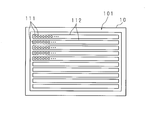
- FIG. 3 is an explanatory diagram schematically illustrating an arrangement example of a plurality of light sources in the light source device according to the first embodiment.
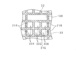
- 2 is an explanatory diagram illustrating a light receiving sensor according to Embodiment 1.
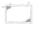
- FIG. 3 is an explanatory diagram schematically showing the arrangement of light receiving sensors in the first embodiment.
- 3 is a functional block diagram illustrating functions realized by a display control unit in Embodiment 1.
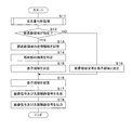
- FIG. 6 is a flowchart illustrating an example of a processing procedure executed by the display control unit according to the first embodiment.
- FIG. 10 is a flowchart illustrating an example of a processing procedure executed by the display control unit according to the second embodiment.
- 10 is a flowchart illustrating an example of a procedure of received light amount determination processing according to the second embodiment. It is explanatory drawing of the example of a display in Embodiment 2 when a shield exists on a display part.
- FIG. 14 is a flowchart illustrating an example of a processing procedure executed by a display control unit according to the third embodiment. It is explanatory drawing of the example of a display in Embodiment 3 when a shield exists on a display part.
- FIG. 1 is an explanatory diagram showing an outline of the present invention.
- the information processing apparatus 1 is a tablet PC to which the present invention is applied.
- the information processing apparatus 1 displays an image on the display unit 100.
- the explanatory diagram of FIG. 1 shows a state in which the information processing apparatus 1 is placed with the surface of the display unit 100 facing upward. Further, documents P1 and P2 are placed so as to cover a part of the surface of the display unit 100. Thereby, the image currently displayed on the said part of the surface of the display part 100 is shielded, and visual recognition is difficult.
- the image displayed on the display unit 100 is displayed in the remaining part other than the part. To do. As a result, the user can accurately confirm the contents of the displayed image without removing the documents P1 and P2.
- Embodiments 1 to 3 will be disclosed below and will be described in detail below for each configuration for realizing such display control.
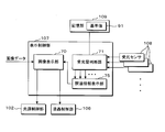
- FIG. 2 is a block diagram illustrating a configuration of the information processing apparatus 1 according to the first embodiment.
- the information processing apparatus 1 is configured by housing a control unit 11, a temporary storage unit 12, a storage unit 13, an operation unit 14, and a display unit 100 in a housing 10.
- the control unit 11 uses a CPU (Central Processing Unit).
- the control unit 11 causes the tablet PC to function as the information processing apparatus 1 by reading and executing a computer program (not shown) stored in the storage unit 13.
- the temporary storage unit 12 uses a RAM such as DRAM (Dynamic Random Access Memory) or SDRAM (Synchronous DRAM).
- the temporary storage unit 12 temporarily stores information generated by the processing of the control unit 11.
- the storage unit 13 uses a flash memory. In addition to the computer program read by the control unit 11, the storage unit 13 stores a plurality of image data to be displayed on the display unit 100. Note that a storage device other than a flash memory may be used for the storage unit 13.
- the operation unit 14 uses a touch panel built in the display unit 100 and a button group (not shown) provided in the housing 10.
- the operation unit 14 notifies the control unit 11 of presence / absence of contact by the user and position information of the contact location on the touch panel. Further, the operation unit 14 notifies the control unit 11 of information such as button presses and press times.
- the control unit 11 outputs the image data stored in the storage unit 13 to the display unit 100 based on the operation by the user detected by the operation unit 14 and causes the display unit 100 to display the image data.
- the display unit 100 includes a light source device 101, a light source control unit 102, a liquid crystal panel 103, a gate driver 104, a source driver 105, a liquid crystal control unit 106, a display control unit 107, a light receiving sensor 108, a storage unit 109, and a temporary storage unit 110.
- the light source device 101 includes a plurality of light sources 111 (see FIG. 3) disposed on the bottom surface of the chassis 10a of the housing 10, a control circuit for each of the light sources 111, and an optical sheet (not shown).
- the light source 111 uses, for example, a light emitting diode (LED) and is arranged in a grid on the bottom surface of the chassis 10a.
- the light source device 101 controls lighting / extinction and brightness / darkness of each of the plurality of light sources 111 by a control circuit.
- the light source control unit 102 Based on the light source control signal from the display control unit 107, the light source control unit 102 generates a control signal for controlling turning on / off and brightness of each of the plurality of light sources 111 and outputs the control signal to the light source device 101. Circuit.
- the liquid crystal panel 103 is a rectangular display panel and adopts an active matrix method.
- each element such as a color filter, an electrode, an electrode for driving a liquid crystal, a transistor connected to the electrode, and an auxiliary capacitor is formed on a pair of translucent rectangular substrates, Two substrates are bonded to face each other, and a liquid crystal material containing liquid crystal molecules is injected into a space provided between the substrates.
- the liquid crystal panel 103 has a pixel region 31 in which a plurality of pixels 30 (see FIG. 4) for realizing image display are arranged in a grid pattern.
- the electrodes of each substrate are arranged in parallel in the pixel region 31 so as to correspond to each pixel 30.
- Each pixel 30 includes two subpixels 30R, 30R, 30G, 30G, 30B, and 30B for each of a plurality of different colors (R (red), G (green), and B (blue)), and each electrode is a subpixel. It is arranged side by side to correspond to. Thin film transistors (TFTs) and auxiliary capacitors are connected to electrodes (pixel electrodes) on one substrate. A source bus line, a gate bus line, and an auxiliary capacitor bus line for supplying a voltage signal to the source electrode, the gate electrode, and the other electrode of the auxiliary capacitor are formed.
- TFTs Thin film transistors
- auxiliary capacitors are connected to electrodes (pixel electrodes) on one substrate.
- the gate driver 104 is connected to the gate bus line.
- the gate driver 104 outputs a gate signal to the gate electrode of the thin film transistor connected to the pixel electrode, and controls on / off of the thin film transistor.
- the source driver 105 is connected to the source bus line.
- the source driver 105 outputs a source signal to the source electrode of the thin film transistor connected to the pixel electrode, and controls the electric field strength applied to the liquid crystal layer.
- the liquid crystal control unit 106 outputs a control signal to the gate driver 104 and the source driver 105 based on the image signal given from the display control unit 107.
- the display control unit 107 uses a GPU (Graphics Processing Unit).
- the display control unit 107 outputs an image signal to the liquid crystal control unit 106 and outputs a light source control signal to the light source control unit 102 based on the image data given from the control unit 11. Further, the display control unit 107 determines whether or not there is a shielding object covering the pixel region 31 based on data from the light receiving sensor 108 or data from other sensors, and performs control to display an image according to the presence or absence of the shielding object. Do.
- the light receiving sensor 108 uses an optical element such as a photodiode, a phototransistor, or a photoresistor.
- the light receiving sensor 108 outputs electrical information corresponding to the amount of received light.
- Information from the light receiving sensor 108 is input by the display control unit 107.
- the light receiving sensors 108 are provided at a plurality of locations on the pixel region 31. In the first embodiment, one or a plurality of light receiving sensors 108 are provided for each pixel 30. Note that one light receiving sensor 108 may be provided for each pixel group (for example, 8 ⁇ 8 pixels, 10 ⁇ 10 pixels, or the like) including a plurality of pixels 30, or one at the four corners and the center of the pixel region 31. It is good also as a structure provided one by one.
- the storage unit 109 uses a flash memory. Various ROMs may be used.
- the storage unit 109 stores a control program read by the display control unit 107.
- the storage unit 109 stores various information such as values (predetermined values or predetermined ratios) to be referred to by the display control unit 107 or position information of each of the plurality of light receiving sensors 108. is there. Note that values serving as various determination criteria may be rewritable in accordance with an instruction from the control unit 11 via the display control unit 107, or the display control unit 107 may determine whether the determination criteria are determined according to ambient light. You may make it change the value which becomes.
- the temporary storage unit 110 uses a RAM such as a DRAM or SDRAM. The temporary storage unit 110 temporarily stores information generated by the processing of the display control unit 107.
- the display unit 100 configured as described above, when the display control unit 107 displays an image on the pixel region 31 based on the image data provided from the control unit 11, the display unit 100 is shielded when a shielding object is present on the pixel region 31.
- the details of the control for displaying an image in the remaining part not covered with an object will be described below.
- FIG. 3 is an explanatory diagram schematically illustrating an arrangement example of the plurality of light sources 111 in the light source device 101 according to the first embodiment.
- FIG. 3 shows the arrangement of the light sources 111 when the light source device 101 is viewed from the opening of the chassis 10a where the plurality of light sources 111 are installed.
- the light source 111 is juxtaposed on the long substrate 112 in the longitudinal direction.
- a plurality of light sources 111 are juxtaposed in a grid pattern by arranging a plurality of substrates 112 in the short-side direction along the longitudinal direction of the casing 10 of the information processing apparatus 1.
- the substrate 112 is formed with a control circuit (not shown) that controls lighting / extinction and brightness of each light source 111 based on a control signal from the light source control unit 102.
- a control circuit (not shown) that controls lighting / extinction and brightness of each light source 111 based on a control signal from the light source control unit 102.
- the arrangement of the plurality of light sources 111 is not limited to this. For example, it may be a staggered or zigzag arrangement in which the positions of the plurality of light sources 111 are shifted for each row or for each plurality of rows.
- FIG. 4 is an explanatory diagram showing the light receiving sensor 108 according to the first embodiment.
- FIG. 4 is an enlarged view of the substrate facing the substrate on which the pixel electrode is provided. As shown in FIG. 4, the substrate is provided with a color filter 21R, 21G, 21B for each color of RGB, and a black matrix 22 made of a resin film using carbon black or the like, and further, a light receiving sensor 108 is disposed.
- one pixel 30 includes six sub-pixels 30R, 30R, 30G, 30G, 30B, and 30B, and is arranged in a 2 ⁇ 3 grid.
- One light receiving sensor 108 is provided in each pixel 30 in a horizontally long manner so as to extend in three rows above the sub-pixels 30R, 30R, 30G, 30G, 30B, and 30B. It goes without saying that the light receiving sensor 108 is not limited to the configuration provided as shown in FIG.
- the light receiving sensors 108 may be provided on the black matrix 22 so as to be arranged in a lattice pattern, one for each group of the plurality of pixels 30 in order to suppress the amount of decrease in the amount of light.
- FIG. 5 is an explanatory diagram schematically showing the arrangement of the light receiving sensors 108 in the first embodiment.
- FIG. 5 shows the front of the liquid crystal panel 103. Since one light receiving sensor 108 is provided for each pixel 30 as shown in FIG. 4, the light receiving sensors 108 are arranged in parallel on the pixel region 31 as shown in FIG. 5.
- the storage unit 109 stores information on the position (v, h) of the light receiving sensor 108 and the plurality of light receiving sensors 108 in association with each other, and the display control unit 107 stores the position of the light receiving sensor 108. And the received light amount data of each of the light receiving sensors 108 can be acquired.
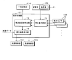
- FIG. 6 is a functional block diagram illustrating functions realized by the display control unit 107 in the first embodiment.
- the display control unit 107 functions as a received light amount determination unit 71, a shielded region specifying unit (specifying unit) 72, and an image display unit 73.
- the received light amount determination unit 71 inputs received light amount data from the plurality of light receiving sensors 108, and the received light amount at each light receiving sensor 108 is a reference value (first value) among a plurality of predetermined values stored in the storage unit 109. It is determined whether or not the predetermined value is 91 or less, and the determination result is output. In the first embodiment, the received light amount determination unit 71 determines whether the light reception sensor 108 provided in each pixel 30 is equal to or less than the reference value 91 and outputs a determination result.
- the shielded area specifying unit 72 specifies the shielded area (or remaining part) covered by the shielding object based on the determination result of the received light amount determining unit 71 with respect to the received light amount in each light receiving sensor 108 and the position of each light receiving sensor 108.
- the coordinate information on the pixel area 31 is obtained.
- the shielded area specifying unit 72 determines that the shield is present only when it is determined that the determination result regarding the light reception amount in the plurality of pixels 30 continuously extending in a planar shape is the reference value 91 or less. Identify the occluded area or the remainder.
- the shielded region specifying unit 72 is configured to block the shielding object when the corresponding pixel 30 does not have a planar shape. Is not present, and the shielded area or the remaining part is not specified. Further, the shielded area specifying unit 72 determines whether or not the contour of the shape of the shielded area to be specified includes a linear outline, or whether or not the shielded area includes the outer edge of the pixel area 31. By performing the above, it may be possible to accurately determine the presence or absence of the shielding object.
- the image display unit 73 determines a display region for displaying an image based on the image data given from the control unit 11 based on the coordinate information of the shielded region specified by the shielded region specifying unit 72.
- the image display unit 73 generates an image signal so that an image is displayed in the determined display area, and generates a light source control signal so as to reduce the light quantity of the shielded area or the area outside the display area, Is output to the liquid crystal control unit 106 and the light source control unit 102.
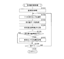
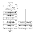
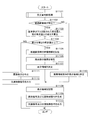
- FIG. 7 is a flowchart illustrating an example of a processing procedure executed by the display control unit 107 according to the first embodiment.
- the display control unit 107 periodically repeats the following processing at regular time intervals such as 500 milliseconds.
- the display control unit 107 performs a received light amount determination process (step S11), whereby information on the position of the light receiving sensor 108 at which the received light amount is determined to be equal to or less than the reference value 91 is stored in the temporary storage unit 110.
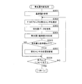
- FIG. 8 is a flowchart illustrating an example of a procedure of received light amount determination processing.
- the processing procedure shown in the flowchart of FIG. 8 corresponds to the details of step S11 of the flowchart of FIG.
- the display control unit 107 refers to the reference value 91 for the amount of received light from the storage unit 109 (step S101).
- the display control unit 107 selects one light receiving sensor 108 among the plurality of light receiving sensors 108 (step S102).
- the display control unit 107 acquires received light amount data of the selected light receiving sensor 108 (step S103).
- the display control unit 107 compares the received light amount obtained based on the acquired received light amount data with the reference value 91 (step S104), and determines whether the received light amount is equal to or less than the reference value 91 (step S105). .
- the display control unit 107 determines whether or not the comparison has been completed for all the light receiving sensors 108 (step S106). If the display control unit 107 determines that it is not completed (S106: NO), the process returns to step S102 to select the next one light receiving sensor 108 from the plurality of light receiving sensors 108.
- step S105 determines in step S105 that the amount of received light is equal to or less than the reference value 91 (S105: YES)
- the display control unit 107 displays the position of the selected light receiving sensor 108 (information on (v, h)).
- the position information indicating the shielding area is stored in the temporary storage unit 110 (step S107), and the process proceeds to step S106. If the display control unit 107 determines in step S106 that the process has been completed (S106: YES), the display control unit 107 returns the process to step S12 in the flowchart of FIG.
- the display control unit 107 determines whether or not the shielded area is specified based on the position information group stored in the temporary storage unit 110 (step S12). Specifically, at this time, the display control unit 107 determines whether or not the position information group stored in the temporary storage unit 110 corresponds to a continuous position in a planar shape as described above. The display control unit 107 determines that the position information group is not specified when the position information group corresponds to the discontinuous positions and is discrete. If it is determined that the shielded area has been specified, it is determined that there is a shield.
- the display control unit 107 determines that the shielded area has been identified in step S12 (S12: YES)
- the coordinate information of the identified shielded area (for example, coordinate information corresponding to the apex of the outline of the shielded area) ) Is stored in the temporary storage unit 110 (step S13).
- the display control unit 107 identifies the remaining pixels based on the coordinate information of the shielded area stored in the temporary storage unit 110 (step S14), and includes a part or all of the identified remaining pixels.
- a display area is determined (step S15).
- the image display unit 73 determines that the display area is the largest rectangle among the rectangles inscribed in the shape of the remaining portion.
- the display control unit 107 may determine a rectangle and a display area that have the same aspect ratio as the aspect ratio of the pixel area 31 among the rectangles inscribed in the shape of the remaining portion.
- the display control unit 107 stores the display area determined in step S15 in the temporary storage unit 110 (step S16), and displays an image signal to display an image based on the image data output from the control unit 11 in the display area. Then, a light source control signal is generated (step S17), and output to the liquid crystal control unit 106 and the light source control unit 102 (step S18), and the process ends.
- step S12 determines whether the area to be shielded is not specified (S12: NO). If it is determined in step S12 that the area to be shielded is not specified (S12: NO), the display control unit 107 determines the entire pixel area 31 as a display area (step S19), and proceeds to step S16.
- the display control unit 107 generates and outputs an image signal based on the image data output from the control unit 11 so as to display in the determined display area until the next processing of steps S11 to S19. Keep doing.
- step S12 determines whether the amount of received light based on the amount of received light acquired from some of the light receiving sensors 108 is equal to or less than the reference value 91. If the amount of received light based on the amount of received light acquired from some of the light receiving sensors 108 is equal to or less than the reference value 91, the process proceeds to step S14 where an image is displayed in the remaining portion. Processing may proceed.
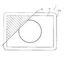
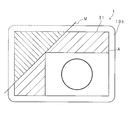
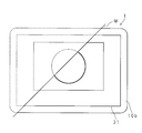
- FIG. 9 and FIG. 10 are explanatory diagrams of display examples in the first embodiment when a shielding object is present on the display unit 100.
- FIG. 9 shows a display example in which an image is displayed using the pixels in the pixel region 31 as a whole for comparison, and
- FIG. 10 shows that the display control unit 107 determines that the shielded region is specified.
- a display example is shown.
- symbol M in FIG.9 and FIG.10 is a shield.
- the shielding object M when an image is displayed using the pixel region 31 as a whole, when the shielding object M is placed on the information processing apparatus 1, the shielding object M is a part of the display unit 100. Cover the part. Thereby, a part of the pixel area 31 becomes a shielded area indicated by hatching, and a part of the displayed image cannot be visually recognized.
- the display area indicated by the symbol A when it is determined that the shielded area is specified, the display area indicated by the symbol A is determined by the process based on the function of the image display unit 73 of the display control unit 107. In the display area A, an image is displayed so as not to be shielded by the shield M.
- the display control unit 107 may reduce the amount of light of the light source 111 at the corresponding position for the shielded area, or may correspond to the corresponding area for the area other than the display area A in the remaining part. The amount of light from the light source 111 may be reduced.
- FIG. 11 is a functional block diagram illustrating functions realized by the display control unit 107 according to the second embodiment. Functions common to those in the first embodiment are denoted by the same reference numerals, and detailed description thereof is omitted.
- the display control unit 107 according to the second embodiment functions as a received light amount determination unit 71, a non-shielding region specifying unit 72, and a priority image display unit 74.
- the priority image display unit 74 is a display region (display position and size) for displaying a plurality of images based on the image data given from the control unit 11 based on the coordinate information of the shielded region specified by the shielded region specifying unit 72. ).
- the image data output from the control unit 11 to the display control unit 107 includes image information to be displayed for each object, and the image information includes a priority.
- the priority is given from the control unit 11 based on whether or not the image is selected and activated by the operation unit 14.
- the priority image display unit 74 generates an image signal so that an image having a high priority is preferentially displayed based on image information for each object included in the image data.
- a light source control signal is generated so as to reduce the amount of light in the region, and each is output to the liquid crystal control unit 106 and the light source control unit 102.
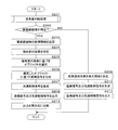
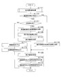
- FIG. 12 is a flowchart illustrating an example of a processing procedure executed by the display control unit 107 according to the second embodiment.
- the display control unit 107 periodically repeats the following processing at regular time intervals such as 500 milliseconds.
- the display control unit 107 performs a received light amount determination process (step S201), whereby information on an area where the received light amount is determined to be equal to or less than a predetermined reference value 91 is stored in the temporary storage unit 110.
- FIG. 13 is a flowchart illustrating an example of a procedure of received light amount determination processing according to the second embodiment.
- the processing procedure shown in the flowchart of FIG. 13 corresponds to the details of step S201 in the flowchart of FIG.
- the display control unit 107 refers to the reference value 91 for the amount of received light from the storage unit 109 (step S301), and selects one light receiving sensor 108 (step S302).
- the display control unit 107 does not acquire received light amount data from all the received light sensors 108 corresponding to each of the plurality of pixels 30, but selects them by thinning. Specifically, the display control unit 107 selects one light receiving sensor 108 for each block including 16 ⁇ 16 pixels 30 in the pixel region 31, for example, the light receiving sensor 108 corresponding to the center of each block. As a result, the number of determinations by the received light amount determination unit 71 is reduced.
- the light receiving sensor 108 may be provided in advance for each block of 16 pixels ⁇ 16 pixels, instead of being provided corresponding to all the pixels 30. In this case, in the pixel region 31, a region where the light from the light source device 101 is shielded by the light receiving sensor 108 is reduced, and the light amount can be maintained at high luminance.
- the display control unit 107 acquires the received light amount data of the selected light receiving sensor 108 (step S303), compares the received light amount obtained based on the acquired received light amount data with the reference value 91 (step S304), and the received light amount is It is determined whether or not the reference value is 91 or less (step S305). If the display control unit 107 determines that the value is higher than the reference value 91 (S305: NO), the display control unit 107 determines whether or not the comparison of the light receiving sensors 108 of all blocks is completed (step S306). If the display control unit 107 determines that it is not completed (S306: NO), it returns the process to step S302 to select the light receiving sensor of the next block.
- step S305 If the display control unit 107 determines in step S305 that the reference value is 91 or less (S305: YES), the display control unit 107 stores the block position information of the selected light receiving sensor 108 in the temporary storage unit 110 (step S307). The process proceeds to step S306. If the display control unit 107 determines in step S306 that the process has been completed (S306: YES), the display control unit 107 returns the process to step S202 in the flowchart of FIG.
- the display control unit 107 determines whether or not the shielded area is specified based on the position information stored in the temporary storage unit 110 (step S202). Specifically, in the second embodiment, the display control unit 107 determines whether or not the position information of the block corresponding to the light receiving sensor 108 for which the amount of received light is determined to be equal to or less than the reference value 91 is stored in the temporary storage unit 110. To do. When the display control unit 107 determines that the block is stored, the display control unit 107 specifies the shielded area based on the stored block position information.
- the display control unit 107 determines whether or not the stored blocks are continuous in a planar shape, and determines that the shielded area is not specified in the case of discontinuity. If it is determined that the shielded area has been specified, it is determined that there is a shield.
- the display control unit 107 determines that the shielded area is specified in step S202 (S202: YES)
- the coordinate information of the specified shielded area (for example, coordinates corresponding to the apex of the outline of the shielded area) Information) is stored in the temporary storage unit 110 (step S203).
- the display control unit 107 specifies the remaining pixels based on the coordinate information of the shielded area stored in the temporary storage unit 110 (step S204).
- the display control unit 107 selects an object based on the priority level of each object based on the image information for each object included in the image data obtained from the control unit 11 (step S205).
- the display control unit 107 generates an image signal based on the selected object (step S206). Note that the detailed description of the image signal generation processing based on the priorities in steps S205 and S206 is omitted.
- various methods disclosed in International Publication No. WO2011 / 125271, International Publication No. WO2011 / 052331, and International Publication No. WO2011 / 121687 can be adopted.
- the display control unit 107 reduces the light amount of the light source 111 corresponding to the shielded area and generates a light source control signal corresponding to the generated image signal (step S207).
- the display control unit 107 outputs the generated image signal and light source control signal to the light source control unit 102 and the liquid crystal control unit 106 (step S208), and ends the process.
- step S202 When it is determined in step S202 that the shielded area is not specified (S202: NO), the display control unit 107 determines the entire pixel area as the display area (step S209), and the control unit 11 The image signal and the light source control signal are generated based on the image information for each object included in the image data obtained from (Step S210), the generated image signal and the light source control signal are output (Step S211), and the process is terminated. To do.
- FIG. 14 and 15 are explanatory diagrams of display examples in the second embodiment in the case where a shielding object is present on the display unit 100.
- FIG. 14 shows a display example in which an image is displayed using the pixels in the pixel region 31 as a whole for comparison.
- FIG. 15 shows that the display control unit 107 determines that the shielded region is specified. A display example is shown.
- symbol M in FIG.14 and FIG.15 is a shield.
- the shielding object M is placed on the information processing apparatus 1.
- the shield M covers a part of the display unit 100.
- a part of the image area 31 becomes a shielded area indicated by hatching, and a part of the displayed image cannot be visually recognized.
- the process of the display control unit 107 causes the object O1 to be as much as possible without being occluded in the remaining pixels. It is displayed to be larger.
- the object O2 is displayed at a position where it can be displayed as large as possible within the area occupied by the image of the remaining object O1. At this time, the image of the object O2 is partially included in the shielded area. At least an image of the object O ⁇ b> 1 having a high priority, for example, an image of the object O ⁇ b> 1 selected and active is displayed so as to avoid the shielding object M. Therefore, the user can check the content of the image of the object O1 having a high priority without removing the shielding object M.
- the display control unit 107 may reduce the light amount of the light source 111 at the corresponding position for the shielded area, or may be an area other than the range occupied by the display positions and sizes of the objects O1 and O2. Also, the light quantity of the light source 111 at the corresponding position may be reduced.
- FIG. 16 is a flowchart illustrating another example of the procedure of received light amount determination processing according to the second embodiment. In the following processing procedure, steps that are the same as those in the flowchart of FIG. 12 are given the same step numbers, and detailed description thereof is omitted.
- the display control unit 107 determines that the shielded area is specified in step S202 (S202: YES), the coordinate information of the specified shielded area (for example, coordinates corresponding to the apex of the outline of the shielded area) Information) is stored in the temporary storage unit 110 (step S203).
- the display control unit 107 specifies the remaining pixels (S204), selects an object (S205), generates an image signal based on the selected object (step S206), and generates a corresponding light source control signal (S207). ).
- the display control unit 107 outputs the generated image signal and light source control signal to the light source control unit 102 and the liquid crystal control unit 106 (S208).
- the display control unit 107 intermittently switches the output (step S212) and ends the process. Note that the timing of intermittent switching in step S212 is, for example, once every 10 seconds for 3 seconds.
- FIG. 17 is an explanatory diagram of another display example in the second embodiment when a shielding object is present on the display unit 100.
- FIG. 17 shows a display example when the display control unit 107 determines that the shielded area is specified.
- the display example shown in FIG. 14 corresponds.
- symbol M in FIG. 17 is a shielding object.
- the left part of FIG. 17 shows an example in which an image of an object with a high priority is displayed, and the right part shows an example in which the image display is switched to an object with a low priority. As illustrated in FIG.
- the object O1 when it is determined that the area to be shielded is specified, the object O1 is shielded within the remaining pixels by the processing based on the function of the priority image display unit 74 of the display control unit 107. It is displayed as large as possible without any problem. Then, the object O2 is intermittently displayed in the same manner.
- the timing at which the object O2 is intermittently displayed is, for example, 3 seconds out of 10 seconds as described above. As a result, the user can check the content of the image of the object O2 having a low priority without removing the shielding object M.
- the related information of the displayed image is displayed superimposed on the image in a caption form. Since the hardware configuration of the information processing apparatus 1 in the third embodiment is the same as that of the first embodiment, the same reference numerals are given to the hardware configuration, and detailed description thereof is omitted.
- FIG. 18 is a functional block diagram showing functions realized by the display control unit 107 in the third embodiment.
- the display control unit 107 in the third embodiment functions as an image display unit 70, a received light amount determination unit 71, and a related information display unit 75. Since the function of the received light amount determination unit 71 is the same as the function shown in the first embodiment, detailed description thereof is omitted.
- the image display unit 70 generates an image signal for displaying an image based on the image data given from the control unit 11 over the entire pixel area 31, generates a light source control signal corresponding to the image signal, and each of them generates a liquid crystal control unit 106. And output to the light source controller 102. Further, the image display unit 70 controls the liquid crystal so that the related information included in the image data given from the control unit 11 is displayed in a subtitle shape when the related information display unit 75 determines to display the related information.
- the image signal is output to the unit.
- the related information includes characters or images.
- the subtitle shape is a state in which characters or images are displayed statically or with a movement such as scrolling or blinking using a horizontally or vertically long area at the end of the pixel area 31.
- the image display unit 70 generates an image signal so that the related information is displayed superimposed on the image included in the image data, and outputs the image signal to the liquid crystal control unit 106.
- the related information display unit 75 determines display / non-display of related information based on the determination result of the light reception amount determination unit 71 with respect to the amount of light received by each light reception sensor 108 and the position of each light reception sensor 108. Specifically, when the position information is not stored in the temporary storage unit 110, the related information display unit 75 determines that no related information is displayed because there is no shielding object on the pixel region 31. The related information display unit 75 determines whether or not the stored position information group corresponds to a continuous position in a planar shape even when the position information is stored in the temporary storage unit 110.
- the related information display unit 75 may determine to display related information when at least one position information group is stored. The related information display unit 75 may determine that the related information is displayed when the received light amount based on the received light amount data in the specific light receiving sensor 108 is the reference value 91 or less.
- FIG. 19 is a flowchart illustrating an example of a processing procedure executed by the display control unit 107 according to the third embodiment.
- the display control unit 107 periodically repeats the following processing at regular time intervals such as 500 milliseconds.
- the display control unit 107 performs the received light amount determination process shown in the flowchart of FIG. 8 or 13 (step S51), and determines whether or not to display related information based on the position information group stored in the temporary storage unit 110. Judgment is made (step S52). If the display control unit 107 determines that there is an obstacle and displays related information (S52: YES), an image signal that displays the related information in a subtitle form based on the image data obtained from the control unit 11, and A light source control signal corresponding to the image signal is generated (step S53), and output to the liquid crystal control unit 106 and the light source control unit 102 (step S54), and the process ends.
- step S52 determines not to display in step S52 (S52: NO)
- the display control unit 107 displays an image signal that does not include related information, and the image signal.
- a light source control signal is generated (step S55), and output to the liquid crystal control unit 106 and the light source control unit 102 (S54), and the process ends.
- FIGS. 20 to 23 are explanatory diagrams of display examples in the third embodiment in the case where there is a shielding object on the display unit 100.
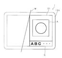
- FIG. FIG. 20 shows a display example before displaying the related information as a comparison
- FIGS. 21 to 23 show display examples of the related information when the display control unit 107 determines to display the related information.
- a symbol M in FIGS. 20 to 23 is a shield.
- the shielding object M is one of the display units 100. Cover the part. Thereby, a part of the pixel area 31 becomes a shielded area indicated by hatching, and a part of the displayed image cannot be visually recognized.
- the shield M is present, and the related information is displayed by the processing of the display control unit 107.
- the size of the character or image is adjusted so that the related information fits in the remaining portion, and the image is output separately from the image based on the image data and the related information. It is.
- the display control unit 107 determines whether or not the ratio of the remaining area to the pixel region 31 is equal to or higher than a predetermined ratio, and determines that the ratio is equal to or higher than the predetermined ratio. Only in such a case, the image is divided into an image display area A and a related information display area G.
- the display control unit 107 can generate and output a light source control signal for each of the display area A and the related information display area G, thereby realizing display with appropriate brightness and further improving visibility. Can be increased. Thus, even when the shielding object M exists, the user can obtain information that supplements the content of the displayed image by the related information, and can confirm the content of the image.
- the display control unit 107 is configured to generate an image signal to display related information superimposed on a caption, it may be displayed using OSD (On Screen Display).
- the display control unit 107 may display the related information only when the area of the remaining part is equal to or less than a predetermined ratio with respect to the pixel region 31 by the function of the related information display unit 75.
- a predetermined ratio for example, an appropriate ratio such as 30%, 20%, etc. is set in advance.
- the related information display unit 75 may determine whether the area of the shielded area is equal to or greater than a predetermined ratio of the pixel area 31.
- FIG. 24 is a flowchart illustrating another example of the processing procedure executed by the display control unit 107 according to the third embodiment.
- the display control unit 107 performs the received light amount determination process shown in the flowchart of FIG. 8 or 13 (step S71), and based on the position information group stored in the temporary storage unit 110, the area of the remaining part outside the shielded region It is determined whether or not the proportion of the pixel area 31 is equal to or less than a predetermined proportion (step S72). In step S72, whether or not the remaining part includes the central part may be added to the determination. If the display control unit 107 determines that the ratio is equal to or less than the predetermined ratio in step S72 (S72: YES), the display control unit 107 specifies the remaining pixels (step S73). The display control unit 107 determines the related information display area G in order to display the related information within the specified remaining portion of the pixels (step S74).
- the display control unit 107 sets the size of characters and images of related information displayed in the related information display area G determined in step S74 (step S75). In step S75, the display control unit 107 adjusts the size of the character or image so that the character or image as the related information is appropriately displayed in the related information display area G.
- the display control unit 107 generates an image signal for displaying related information and a light source control signal corresponding to the image signal (step S76).
- the display control unit 107 outputs the generated image signal and light source control signal to the liquid crystal control unit 106 and the light source control unit 102 (step S77), and ends the process.
- step S72 If the display control unit 107 determines in step S72 that the area occupied by the remaining area is higher than the predetermined ratio (S72: NO), the display control unit 107 does not include related information based on the image data obtained from the control unit 11.
- An image signal for displaying an image and a light source control signal corresponding to the image signal are generated (step S78), and output to the liquid crystal control unit 106 and the light source control unit 102 (S77), and the process ends.
- the light receiving sensor 108 is configured to be provided in a grid pattern evenly in the pixel region 31.
- the light receiving sensor 108 is provided in a part (central part) of the pixel region 31, and Based on the amount of light received by the light receiving sensor 108, the presence / absence of a shielding object may be determined, and display control may be performed when the shielding object is present.
- the central portion does not mean only the center in the strict sense but has a meaning in the vicinity of the center.
- FIG. 25 is an explanatory view schematically showing another arrangement example of the light receiving sensor 108.
- FIG. 25 shows the front of the liquid crystal panel 103.
- only one light receiving sensor 108 is provided in the central portion on the pixel region 31.
- the display control unit 107 sets the reference amount of a plurality of predetermined values stored in the storage unit 109 for the amount of light received by the light receiving sensor 108. It is determined whether or not the value is 91 or less, and when it is determined that the value is 91 or less, the related information is displayed as described in the third embodiment. Thereby, the information which supplements the content of the image currently displayed can be obtained, without a user removing a shield.
- the shielded area includes the central portion, it may be difficult to visually recognize the image on the pixel area 31.
- information supplementing the contents can be provided to the user.
- FIG. 26 is an explanatory diagram schematically illustrating another arrangement example of the plurality of light receiving sensors 108.
- FIG. 26 shows the front of the liquid crystal panel 103.
- the plurality of light receiving sensors 108 are arranged in a cross shape that passes near the center of the pixel region 31.
- the display control unit 107 may make a determination based only on the amount of light received by the light receiving sensor 108c at the center, or may be determined together with the amounts of light received by the plurality of light receiving sensors 108 near the center including the light receiving sensor 108c. .
- the display control unit 107 further determines the presence or absence of a shield covering the pixel area 31 when the received light amount on the pixel area 31 has a difference equal to or larger than a second predetermined value. You may make it judge that the to-be-shielded area
- the display control unit 107 inputs the received light amount data from the plurality of received light sensors 108, and the received light amount determined to be higher than the reference value 91 among the plurality of received light amounts based on the input received light amount data. And the amount of received light that is determined to be less than or equal to the reference value 91 is classified. The display control unit 107 determines whether the difference between the one received light amount and the other received light amount is equal to or greater than a second predetermined value among a plurality of predetermined values stored in the storage unit 109. The determination result is output to the shielded area specifying unit 72.
- any light quantity on the pixel area 31 can be excluded as long as it is possible to exclude erroneous determination that a shielding object is present when the received light amount is the reference value 91 or less in the entire pixel area 31. It does not matter whether the amount of light received by the light receiving sensor 108 is compared.
- FIG. 27 is a flowchart illustrating another example of the processing procedure executed by the display control unit 107.
- the display control unit 107 periodically repeats the following processing at regular time intervals such as 500 milliseconds.
- the display control unit 107 performs the received light amount determination process shown in the flowchart of FIG. 8 or 13 (step S1101), and whether or not the shielded area is specified based on the position information group stored in the temporary storage unit 110. Is determined (step S1102).
- the display control unit 107 determines that the shielded area has been identified (S1102: YES)
- the display control unit 107 calculates the difference between the received light amount determined to be the reference value 91 or less and the received light amount determined to be higher than the reference value 91. It is calculated (step S1103), and it is determined whether or not the difference is greater than or equal to a second predetermined value (step S1104).
- the display control unit 107 determines that the difference is greater than or equal to the second predetermined value (S1104: YES)
- the display control unit 107 stores the coordinate information of the specified shielded area in the temporary storage unit 110 (step S1105).
- the display control unit 107 specifies the remaining pixels based on the coordinate information stored in the temporary storage unit 110 (step S1106), and determines a display area including a part or all of the specified remaining pixels. (Step S1107).
- the display control unit 107 stores the determined display area in the temporary storage unit 11 (step S1108).
- the display control unit 107 generates an image signal and a light source control signal corresponding to the image signal in order to display an image based on the image data output from the control unit 11 in the determined display area (step S1109). Each output is output to the liquid crystal control unit 106 and the light source control unit 102 (step S1110), and the process is terminated.
- step S1104 determines in step S1104 that the difference is less than the second predetermined value (S1104: NO)
- the display control unit 107 stops the display because the light reception amount of the entire pixel region 31 is less than or equal to the reference value 91.
- Step S1111 a light source control signal for turning off the light source 111 is output (Step S1112), and the process ends.
- step S1102 determines whether the area to be shielded is not specified (S1102: NO). If it is determined in step S1102 that the area to be shielded is not specified (S1102: NO), the display control unit 107 determines the entire pixel area 31 as a display area (step S1113), and the process proceeds to step S1008.
- the display control unit 107 stops the display and keeps the light source 111 off until the next processing of steps S1101 to S1113 is performed, or from the control unit 11 so as to display in the determined display area.
- the image signal based on the output image data is generated and output.
- FIG. 28 is a block diagram illustrating another configuration of the information processing apparatus 1.
- the hardware configuration of the information processing apparatus 1 described below is the same as the configuration in the first embodiment except that the proximity sensor 113 is provided. Therefore, the same reference numerals are given to common components, and detailed description thereof is omitted.
- the proximity sensor 113 is a sensor that detects whether or not an object has approached within a certain distance.
- the proximity sensor 113 for example, an infrared sensor using infrared reflection is used.
- the proximity sensor 113 is configured by providing a light emitting element and a light receiving element in the vicinity of the outer edge of the opening of the chassis 10b, which is a rectangular frame, so that a display control unit is present when a proximity object exists. 107 is notified.
- the proximity sensor 113 is not limited to the infrared type, and may be any type such as a capacitance type, an induction type, or a magnetic type.
- FIG. 29 is a flowchart illustrating another example of the processing procedure executed by the display control unit 107. It should be noted that the processing procedure shown below is mostly in common with the processing procedure shown in the flowchart of FIG. 27, and therefore, the common processing is denoted by the same step number and detailed description thereof is omitted.
- the display control unit 107 determines the presence or absence of a proximity object based on the proximity sensor 113 (step S1201). If the display control unit 107 determines that there is an adjacent object (S1201: YES), the display control unit 107 stores the coordinate information of the specified shielded area in the temporary storage unit 110 (S1105), and executes the processes of S1106 to S1110.
- step S1201 determines that there is no proximity object in step S1201 (S1201: NO)
- the light reception amount of the entire pixel region 31 is less than or equal to the reference value 91, and thus the display is stopped (S1111). Is output (S1112), and the process ends.
- the present invention when the present invention is applied to the information processing apparatus 1 that is a tablet PC and the information processing apparatus 1 is placed on a desk, for example, an image is appropriately displayed when the pixel area is shielded by a load.
- the control for displaying is described.
- the present invention is not limited to this.
- a display device such as a tablet PC that is used by being placed on a desk and having a display unit as well as a display device that is used with a leg portion, there is a shield on the pixel area. In this case, it is possible to realize an appropriate display.
- SYMBOLS 1 Display apparatus 100 Display part 101 Light source device 102 Light source control part 103 Liquid crystal panel 106 Liquid crystal control part (liquid crystal drive part) DESCRIPTION OF SYMBOLS 107 Display control part 108 Light reception sensor 109 Memory
Landscapes
- Engineering & Computer Science (AREA)
- Theoretical Computer Science (AREA)
- Physics & Mathematics (AREA)
- General Physics & Mathematics (AREA)
- Computer Hardware Design (AREA)
- General Engineering & Computer Science (AREA)
- Human Computer Interaction (AREA)
- Chemical & Material Sciences (AREA)
- Crystallography & Structural Chemistry (AREA)
- Control Of Indicators Other Than Cathode Ray Tubes (AREA)
- Liquid Crystal Display Device Control (AREA)
Abstract
Description
なお、受光量が低い受光センサの位置に基づき、残余部の画素における画像の表示を実行するか否かが決定されてもよい。残余部の画素により適切に画像を表示することが可能であるか否かが判断されることで画像が適切に表示される。
受光センサは画素領域内に格子状に並設されるようにしてもよい。これにより、遮蔽物が覆う範囲を詳細に特定して画像を適切に表示させることが可能となる。
また、画素領域の一部における受光センサでの受光量が基準値以下であって他の一部との受光量の差が所定値以上であるときに遮蔽物が存在すると判断するようにしてもよい。
この場合、選択されなかった画像は残余部にて間欠的に表示されてもよい。
図2は、実施の形態1における情報処理装置1の構成を示すブロック図である。情報処理装置1は、制御部11、一時記憶部12、記憶部13、操作部14、及び表示部100を筐体10内に収容して構成される。
表示制御部107は、一時記憶部110に記憶している位置情報群に基づいて被遮蔽領域が特定されるか否かを判断する(ステップS12)。詳細には、このとき表示制御部107は、一時記憶部110に記憶している位置情報群が、前述したように面状に連続する位置と対応するか否かを判断する。表示制御部107は、位置情報群が不連続な位置に対応し、離散的である場合には、特定されないと判断する。なお、被遮蔽領域が特定されたと判断された場合は、遮蔽物が有ると判断されたこととなる。
実施の形態2では、画素領域31に、複数のオブジェクトの画像を重ねて又は並べて表示している場合に遮蔽物が載置されたときの処理について説明する。実施の形態2における情報処理装置1のハードウェア構成は、実施の形態1と同一である。したがって、ハードウェア構成については同一の符号を付して詳細な説明を省略する。
表示制御部107は、一時記憶部110に記憶している位置情報に基づいて被遮蔽領域が特定されるか否かを判断する(ステップS202)。実施の形態2において詳細には、表示制御部107は、受光量が基準値91以下と判断された受光センサ108に対応するブロックの位置情報が一時記憶部110に記憶されているか否かを判断する。表示制御部107は、記憶されていると判断した場合、記憶されているブロックの位置情報に基づき、被遮蔽領域を特定する。なおこのとき、表示制御部107は、記憶されているブロックが面状に連続するか否かを判断し、不連続の場合には被遮蔽領域が特定されないと判断するようにする。なお、被遮蔽領域が特定されたと判断された場合は、遮蔽物が有ると判断されたこととなる。
実施の形態3では、表示している画像の関連情報を字幕状に画像に重畳させて表示する。実施の形態3における情報処理装置1のハードウェア構成は、実施の形態1と同一であるから、ハードウェア構成については同一の符号を付して詳細な説明を省略する。
100 表示部
101 光源装置
102 光源制御部
103 液晶パネル
106 液晶制御部(液晶駆動部)
107 表示制御部
108 受光センサ
109 記憶部
110 一時記憶部
111 光源
113 近接センサ
30 画素
31 画素領域
71 受光量判断部
72 被遮蔽領域特定部(特定部)
70,73 画像表示部(表示部)
74 優先画像表示部
75 関連情報表示部
Claims (16)
- 複数の画素からなる画素領域を有する表示装置において、
前記画素領域の一部を覆う遮蔽物の有無を判断する遮蔽物判断部と、
該遮蔽物判断部が、遮蔽物有と判断した場合、前記画素領域の内の前記一部を除く残余部の画素にて画像を表示させる表示部と
を備えることを特徴とする表示装置。 - 複数の画素からなる画素領域を有する表示装置において、
前記画素領域の内の異なる位置に設けられ、環境光を受光して受光量データを出力する複数の受光センサと、
前記複数の受光センサから各出力される受光量データに基づき各受光量が第1の所定値以下であるか否かを判断する受光量判断部と、
前記複数の受光センサの内の一部における受光量が第1の所定値以下であると前記受光量判断部が判断した場合、前記画素領域の内、前記複数の受光センサの内の一部に対応する領域を除く残余部の画素にて画像を表示させる表示部と
を備えることを特徴とする表示装置。 - 前記受光量判断部により受光量が第1の所定値以下であると判断された受光センサの位置に基づいて、前記残余部の画素による画像表示の実行/不実行を決定する決定部を更に備える
ことを特徴とする請求項2に記載の表示装置。 - 前記受光センサは、前記画素領域内に格子状に並設されている
ことを特徴とする請求項3に記載の表示装置。 - 前記画素領域上の物体の有無を検知する近接センサを更に備え、
該近接センサが物体無と検知している場合、前記残余部の画素による画像表示を中止するようにしてある
ことを特徴とする請求項1から4のいずれか1つに記載の表示装置 - 前記一部における受光量と他の一部における受光量との差が第2の所定値以上であるか否かを判断する光量差判断部を更に備え、
前記受光量判断部が第1の所定値以下であると判断し、且つ前記光量差判断部が第2の所定値以上であると判断した場合に、前記表示部は残余部の画素にて画像を表示させるようにしてある
ことを特徴とする請求項2から4のいずれか1つに記載の表示装置。 - 前記残余部の面積又は形状を特定する特定部と、
該特定部が特定した前記面積又は形状に応じて、画像の大きさを調整する調整部と
を更に備えることを特徴とする請求項4に記載の表示装置。 - 前記残余部内の画素にて各々優先度が付与されてある複数の画像を表示させる場合、前記優先度の高低に基づき画像を選択して表示させる優先画像表示部
を更に備えることを特徴とする請求項1から7のいずれか1つに記載の表示装置。 - 前記優先画像表示部は、非選択画像を前記残余部内に間欠的に表示させるようにしてあること
を特徴とする請求項8に記載の表示装置。 - 複数の画素からなる画素領域を有する表示装置において、
前記画素領域の一部を覆う遮蔽物の有無を判断する遮蔽物判断部と、
該遮蔽物判断部が、遮蔽物有と判断した場合、表示中の画像に関連付けて記憶してある画像又は文字を含む関連情報を表示させる関連情報表示部と
を備えることを特徴とする表示装置。 - 複数の画素からなる画素領域を有する表示装置において、
前記画素領域の内の異なる位置に設けられ、環境光を受光して受光量データを出力する複数の受光センサと、
前記複数の受光センサから各出力される受光量データに基づき各受光量が第1の所定値以下であるか否かを判断する受光量判断部と、
前記複数の受光センサの内の一部における受光量が第1の所定値以下であると前記受光量判断部が判断した場合、表示中の画像に関連付けて記憶してある画像又は文字を含む関連情報を表示させる関連情報表示部と
を備えることを特徴とする表示装置。 - 前記複数の受光センサの内の1つは、前記画素領域の中央部に設けられており、
前記複数の受光センサの内の1つにおける受光量が第1の所定値以下であると前記受光量判断部が判断した場合、前記関連情報表示部は前記関連情報を表示させるようにしてある
ことを特徴とする請求項10又は11に記載の表示装置。 - 前記画素領域の面積に対する前記残余部の面積の割合が、所定の割合以下であるか否かを判断する面積判断部を更に備え、
該面積判断部が前記所定の割合以下であると判断した場合、前記関連情報表示部が関連情報を表示させるようにしてある
ことを特徴とする請求項10又は11に記載の表示装置。 - 前記関連情報表示部は、前記残余部内に関連情報を表示させるようにしてある
ことを特徴とする請求項10から13のいずれか1つに記載の表示装置。 - 前記関連情報表示部は、前記残余部の大きさ又は形状に応じて関連情報の画像又は文字の大きさを変更して表示させるようにしてある
ことを特徴とする請求項14に記載の表示装置。 - 前記画素領域が設けられている透過型の液晶パネルと、
該液晶パネルの裏面へ平面光を照射する光源装置と、
該光源からの光量を制御する光量制御部と、
前記液晶パネルにおける液晶を前記複数の画素に対応させるように駆動させる液晶駆動部と
を備え、
前記光量制御部は、前記画素領域の内の前記残余部以外の領域を含む一部における光量、又は前記画素領域全部における光量を減少させるようにしてある
ことを特徴とする請求項1から15のいずれか1つに記載の表示装置。
Priority Applications (3)
| Application Number | Priority Date | Filing Date | Title |
|---|---|---|---|
| CN201480032813.7A CN105308670B (zh) | 2014-01-22 | 2014-01-22 | 显示装置 |
| PCT/JP2014/051288 WO2015111158A1 (ja) | 2014-01-22 | 2014-01-22 | 表示装置 |
| US14/894,769 US9858868B2 (en) | 2014-01-22 | 2014-01-22 | Display apparatus for displaying an image outside of a covered region |
Applications Claiming Priority (1)
| Application Number | Priority Date | Filing Date | Title |
|---|---|---|---|
| PCT/JP2014/051288 WO2015111158A1 (ja) | 2014-01-22 | 2014-01-22 | 表示装置 |
Publications (1)
| Publication Number | Publication Date |
|---|---|
| WO2015111158A1 true WO2015111158A1 (ja) | 2015-07-30 |
Family
ID=53680990
Family Applications (1)
| Application Number | Title | Priority Date | Filing Date |
|---|---|---|---|
| PCT/JP2014/051288 Ceased WO2015111158A1 (ja) | 2014-01-22 | 2014-01-22 | 表示装置 |
Country Status (3)
| Country | Link |
|---|---|
| US (1) | US9858868B2 (ja) |
| CN (1) | CN105308670B (ja) |
| WO (1) | WO2015111158A1 (ja) |
Cited By (4)
| Publication number | Priority date | Publication date | Assignee | Title |
|---|---|---|---|---|
| WO2017122363A1 (ja) * | 2016-01-15 | 2017-07-20 | 楽天株式会社 | コンテンツ投影制御装置、コンテンツ投影制御方法及びプログラム |
| WO2017168562A1 (ja) * | 2016-03-29 | 2017-10-05 | 楽天株式会社 | コンテンツ投影制御装置、情報処理方法、プログラム |
| JP2017534072A (ja) * | 2015-10-09 | 2017-11-16 | シャオミ・インコーポレイテッド | 液晶表示ユニットおよび電子機器 |
| US11477424B2 (en) | 2016-03-29 | 2022-10-18 | Rakuten Group, Inc. | Content projection control device, information processing method, and program |
Families Citing this family (8)
| Publication number | Priority date | Publication date | Assignee | Title |
|---|---|---|---|---|
| WO2016098232A1 (ja) | 2014-12-18 | 2016-06-23 | 堺ディスプレイプロダクト株式会社 | 液晶表示装置及び液晶表示装置の駆動方法 |
| CN107710320B (zh) * | 2015-06-23 | 2020-04-17 | 堺显示器制品株式会社 | 液晶显示装置以及液晶显示装置的驱动方法 |
| CN107170770A (zh) * | 2017-05-22 | 2017-09-15 | 安徽大学 | 一种新型rgbled智能芯片 |
| CN108877742A (zh) * | 2018-07-27 | 2018-11-23 | 北京小米移动软件有限公司 | 亮度调整方法及装置 |
| CN109064958A (zh) * | 2018-08-24 | 2018-12-21 | 上海易密值半导体技术有限公司 | 基于GPU的color demura系统 |
| CN109616035B (zh) * | 2018-12-25 | 2021-04-02 | 惠科股份有限公司 | 一种显示面板的驱动方法和显示装置 |
| US20220084447A1 (en) * | 2018-12-25 | 2022-03-17 | Sakai Display Products Corporation | Correction image generation system, image control program, and recording medium |
| TWI795220B (zh) * | 2021-06-23 | 2023-03-01 | 義明科技股份有限公司 | 光學感測器 |
Citations (11)
| Publication number | Priority date | Publication date | Assignee | Title |
|---|---|---|---|---|
| JP2002229546A (ja) * | 2001-02-05 | 2002-08-16 | Sharp Corp | 表示装置 |
| JP2004271866A (ja) * | 2003-03-07 | 2004-09-30 | Canon Inc | 表示装置及び表示装置の制御方法 |
| JP2004302124A (ja) * | 2003-03-31 | 2004-10-28 | Toshiba Corp | 表示装置 |
| JP2005345709A (ja) * | 2004-06-02 | 2005-12-15 | Fuji Photo Film Co Ltd | 画像表示制御テーブル、画像の干渉回避方法及び画像の干渉回避プログラム |
| JP2010507870A (ja) * | 2006-10-24 | 2010-03-11 | アップル インコーポレイテッド | ポータブル・デバイスにおけるユーザ動作に対する自動応答およびユーザ動作の感知 |
| JP2011008111A (ja) * | 2009-06-26 | 2011-01-13 | Canon Inc | 表示装置及びその制御方法 |
| JP2011007833A (ja) * | 2009-06-23 | 2011-01-13 | Seiko Epson Corp | 表示装置の駆動方法 |
| JP2011232979A (ja) * | 2010-04-28 | 2011-11-17 | Sharp Corp | 表示装置 |
| WO2012147686A1 (ja) * | 2011-04-28 | 2012-11-01 | シャープ株式会社 | 表示装置 |
| JP2012252543A (ja) * | 2011-06-03 | 2012-12-20 | Sony Corp | 情報処理装置、情報処理方法、およびプログラム |
| JP2013250680A (ja) * | 2012-05-30 | 2013-12-12 | Sharp Corp | 情報表示装置、当該情報表示装置を備える情報入出力装置、当該情報入出力装置を備える情報入出力システム、および表示方法 |
Family Cites Families (7)
| Publication number | Priority date | Publication date | Assignee | Title |
|---|---|---|---|---|
| JP2007028512A (ja) | 2005-07-21 | 2007-02-01 | Fujifilm Holdings Corp | 表示装置及び撮像装置 |
| JP4650549B2 (ja) * | 2008-10-06 | 2011-03-16 | ソニー株式会社 | 情報処理装置、情報処理方法及びプログラム |
| US8730219B2 (en) | 2009-10-30 | 2014-05-20 | Sharp Kabushiki Kaisha | Display device |
| WO2011121687A1 (ja) | 2010-03-29 | 2011-10-06 | シャープ株式会社 | 表示装置、液晶モジュール及び画像表示システム |
| WO2011125271A1 (ja) | 2010-04-06 | 2011-10-13 | シャープ株式会社 | 表示装置、液晶モジュール及び画像表示システム |
| CN102946459B (zh) * | 2012-11-01 | 2015-04-08 | 广东欧珀移动通信有限公司 | 一种屏幕背光亮度的快捷调节方法及移动终端 |
| WO2015099760A1 (en) * | 2013-12-27 | 2015-07-02 | Intel Corporation | Mechanism for facilitaing flexible wraparound displays for computing devices |
-
2014
- 2014-01-22 CN CN201480032813.7A patent/CN105308670B/zh not_active Expired - Fee Related
- 2014-01-22 WO PCT/JP2014/051288 patent/WO2015111158A1/ja not_active Ceased
- 2014-01-22 US US14/894,769 patent/US9858868B2/en not_active Expired - Fee Related
Patent Citations (11)
| Publication number | Priority date | Publication date | Assignee | Title |
|---|---|---|---|---|
| JP2002229546A (ja) * | 2001-02-05 | 2002-08-16 | Sharp Corp | 表示装置 |
| JP2004271866A (ja) * | 2003-03-07 | 2004-09-30 | Canon Inc | 表示装置及び表示装置の制御方法 |
| JP2004302124A (ja) * | 2003-03-31 | 2004-10-28 | Toshiba Corp | 表示装置 |
| JP2005345709A (ja) * | 2004-06-02 | 2005-12-15 | Fuji Photo Film Co Ltd | 画像表示制御テーブル、画像の干渉回避方法及び画像の干渉回避プログラム |
| JP2010507870A (ja) * | 2006-10-24 | 2010-03-11 | アップル インコーポレイテッド | ポータブル・デバイスにおけるユーザ動作に対する自動応答およびユーザ動作の感知 |
| JP2011007833A (ja) * | 2009-06-23 | 2011-01-13 | Seiko Epson Corp | 表示装置の駆動方法 |
| JP2011008111A (ja) * | 2009-06-26 | 2011-01-13 | Canon Inc | 表示装置及びその制御方法 |
| JP2011232979A (ja) * | 2010-04-28 | 2011-11-17 | Sharp Corp | 表示装置 |
| WO2012147686A1 (ja) * | 2011-04-28 | 2012-11-01 | シャープ株式会社 | 表示装置 |
| JP2012252543A (ja) * | 2011-06-03 | 2012-12-20 | Sony Corp | 情報処理装置、情報処理方法、およびプログラム |
| JP2013250680A (ja) * | 2012-05-30 | 2013-12-12 | Sharp Corp | 情報表示装置、当該情報表示装置を備える情報入出力装置、当該情報入出力装置を備える情報入出力システム、および表示方法 |
Cited By (8)
| Publication number | Priority date | Publication date | Assignee | Title |
|---|---|---|---|---|
| JP2017534072A (ja) * | 2015-10-09 | 2017-11-16 | シャオミ・インコーポレイテッド | 液晶表示ユニットおよび電子機器 |
| US10495911B2 (en) | 2015-10-09 | 2019-12-03 | Xiaomi Inc. | Liquid crystal display assembly and electronic device |
| WO2017122363A1 (ja) * | 2016-01-15 | 2017-07-20 | 楽天株式会社 | コンテンツ投影制御装置、コンテンツ投影制御方法及びプログラム |
| JPWO2017122363A1 (ja) * | 2016-01-15 | 2018-11-01 | 楽天株式会社 | コンテンツ投影制御装置、コンテンツ投影制御方法及びプログラム |
| US10432901B2 (en) | 2016-01-15 | 2019-10-01 | Rakuten, Inc. | Content projection control apparatus, content projection control method and program |
| WO2017168562A1 (ja) * | 2016-03-29 | 2017-10-05 | 楽天株式会社 | コンテンツ投影制御装置、情報処理方法、プログラム |
| JPWO2017168562A1 (ja) * | 2016-03-29 | 2019-03-14 | 楽天株式会社 | コンテンツ投影制御装置、情報処理方法、プログラム |
| US11477424B2 (en) | 2016-03-29 | 2022-10-18 | Rakuten Group, Inc. | Content projection control device, information processing method, and program |
Also Published As
| Publication number | Publication date |
|---|---|
| CN105308670B (zh) | 2017-12-29 |
| CN105308670A (zh) | 2016-02-03 |
| US9858868B2 (en) | 2018-01-02 |
| US20160104435A1 (en) | 2016-04-14 |
Similar Documents
| Publication | Publication Date | Title |
|---|---|---|
| CN105308670B (zh) | 显示装置 | |
| KR102408239B1 (ko) | 연장된 활성 영역을 갖는 전자 디바이스 디스플레이 | |
| JP6088081B2 (ja) | 表示装置 | |
| US8487886B2 (en) | Information input device, information input method, information input/output device, and information input program | |
| US9123285B2 (en) | Transparent display device and transparency adjustment method thereof | |
| US9176625B2 (en) | Information input device, information input method, information input-output device, storage medium, and electronic unit | |
| JP5224973B2 (ja) | 情報入出力装置および情報入出力方法 | |
| US20130009921A1 (en) | Display control device, display control method, and computer program | |
| US20160055823A1 (en) | Electronic device for multi-window display | |
| CN105302418A (zh) | 一种信息处理方法及电子设备 | |
| JP2010097420A (ja) | 表示撮像装置および電子機器 | |
| US20190286295A1 (en) | Fingerprint operation prompting method, display panel and display device | |
| US20150277607A1 (en) | Input device and display device | |
| KR102383992B1 (ko) | 디스플레이 장치 및 디스플레이 장치의 입력 방법 | |
| WO2015111157A1 (ja) | 表示装置 | |
| JP6157971B2 (ja) | 机型表示装置 | |
| US10008139B2 (en) | V-gate layout and gate drive configuration | |
| JP2005293074A (ja) | ポインティングデバイス | |
| CN116860126A (zh) | 显示系统和电子设备 | |
| JP6037744B2 (ja) | タッチスクリーンを具備する電子装置で画面サイズを調節するための方法及びその装置 | |
| JP2009514119A (ja) | ディスプレイ機能を有するボタンを具備した端末機及びこのためのディスプレイ方法 | |
| KR20130115700A (ko) | 유기 발광 다이오드를 이용하여 키패드를 표시하는 방법 및 장치 | |
| JP2010092272A (ja) | 画像表示/像検知装置、補助画像表示方法、およびプログラム | |
| KR20060109618A (ko) | 태블릿 액정표시장치 | |
| JP5886997B2 (ja) | 情報表示装置 |
Legal Events
| Date | Code | Title | Description |
|---|---|---|---|
| WWE | Wipo information: entry into national phase |
Ref document number: 201480032813.7 Country of ref document: CN |
|
| 121 | Ep: the epo has been informed by wipo that ep was designated in this application |
Ref document number: 14879786 Country of ref document: EP Kind code of ref document: A1 |
|
| WWE | Wipo information: entry into national phase |
Ref document number: 14894769 Country of ref document: US |
|
| NENP | Non-entry into the national phase |
Ref country code: DE |
|
| 122 | Ep: pct application non-entry in european phase |
Ref document number: 14879786 Country of ref document: EP Kind code of ref document: A1 |
|
| NENP | Non-entry into the national phase |
Ref country code: JP |