WO2015107994A1 - Aide d'introduction d'outil chirurgical - Google Patents
Aide d'introduction d'outil chirurgical Download PDFInfo
- Publication number
- WO2015107994A1 WO2015107994A1 PCT/JP2015/050500 JP2015050500W WO2015107994A1 WO 2015107994 A1 WO2015107994 A1 WO 2015107994A1 JP 2015050500 W JP2015050500 W JP 2015050500W WO 2015107994 A1 WO2015107994 A1 WO 2015107994A1
- Authority
- WO
- WIPO (PCT)
- Prior art keywords
- treatment instrument
- instrument insertion
- inner tube
- insertion aid
- treatment
- Prior art date
Links
Images


Classifications
-
- A—HUMAN NECESSITIES
- A61—MEDICAL OR VETERINARY SCIENCE; HYGIENE
- A61B—DIAGNOSIS; SURGERY; IDENTIFICATION
- A61B1/00—Instruments for performing medical examinations of the interior of cavities or tubes of the body by visual or photographical inspection, e.g. endoscopes; Illuminating arrangements therefor
- A61B1/00064—Constructional details of the endoscope body
- A61B1/00105—Constructional details of the endoscope body characterised by modular construction
-
- A—HUMAN NECESSITIES
- A61—MEDICAL OR VETERINARY SCIENCE; HYGIENE
- A61B—DIAGNOSIS; SURGERY; IDENTIFICATION
- A61B17/00—Surgical instruments, devices or methods, e.g. tourniquets
- A61B17/34—Trocars; Puncturing needles
- A61B17/3417—Details of tips or shafts, e.g. grooves, expandable, bendable; Multiple coaxial sliding cannulas, e.g. for dilating
- A61B17/3421—Cannulas
- A61B17/3423—Access ports, e.g. toroid shape introducers for instruments or hands
-
- A—HUMAN NECESSITIES
- A61—MEDICAL OR VETERINARY SCIENCE; HYGIENE
- A61B—DIAGNOSIS; SURGERY; IDENTIFICATION
- A61B1/00—Instruments for performing medical examinations of the interior of cavities or tubes of the body by visual or photographical inspection, e.g. endoscopes; Illuminating arrangements therefor
- A61B1/00131—Accessories for endoscopes
- A61B1/0014—Fastening element for attaching accessories to the outside of an endoscope, e.g. clips, clamps or bands
-
- A—HUMAN NECESSITIES
- A61—MEDICAL OR VETERINARY SCIENCE; HYGIENE
- A61B—DIAGNOSIS; SURGERY; IDENTIFICATION
- A61B1/00—Instruments for performing medical examinations of the interior of cavities or tubes of the body by visual or photographical inspection, e.g. endoscopes; Illuminating arrangements therefor
- A61B1/00147—Holding or positioning arrangements
- A61B1/00154—Holding or positioning arrangements using guiding arrangements for insertion
-
- A—HUMAN NECESSITIES
- A61—MEDICAL OR VETERINARY SCIENCE; HYGIENE
- A61B—DIAGNOSIS; SURGERY; IDENTIFICATION
- A61B1/00—Instruments for performing medical examinations of the interior of cavities or tubes of the body by visual or photographical inspection, e.g. endoscopes; Illuminating arrangements therefor
- A61B1/005—Flexible endoscopes
- A61B1/0051—Flexible endoscopes with controlled bending of insertion part
- A61B1/0055—Constructional details of insertion parts, e.g. vertebral elements
-
- A—HUMAN NECESSITIES
- A61—MEDICAL OR VETERINARY SCIENCE; HYGIENE
- A61B—DIAGNOSIS; SURGERY; IDENTIFICATION
- A61B1/00—Instruments for performing medical examinations of the interior of cavities or tubes of the body by visual or photographical inspection, e.g. endoscopes; Illuminating arrangements therefor
- A61B1/012—Instruments for performing medical examinations of the interior of cavities or tubes of the body by visual or photographical inspection, e.g. endoscopes; Illuminating arrangements therefor characterised by internal passages or accessories therefor
-
- A—HUMAN NECESSITIES
- A61—MEDICAL OR VETERINARY SCIENCE; HYGIENE
- A61B—DIAGNOSIS; SURGERY; IDENTIFICATION
- A61B17/00—Surgical instruments, devices or methods, e.g. tourniquets
- A61B17/34—Trocars; Puncturing needles
- A61B17/3494—Trocars; Puncturing needles with safety means for protection against accidental cutting or pricking, e.g. limiting insertion depth, pressure sensors
-
- A—HUMAN NECESSITIES
- A61—MEDICAL OR VETERINARY SCIENCE; HYGIENE
- A61B—DIAGNOSIS; SURGERY; IDENTIFICATION
- A61B17/00—Surgical instruments, devices or methods, e.g. tourniquets
- A61B17/34—Trocars; Puncturing needles
- A61B17/3498—Valves therefor, e.g. flapper valves, slide valves
-
- G—PHYSICS
- G02—OPTICS
- G02B—OPTICAL ELEMENTS, SYSTEMS OR APPARATUS
- G02B23/00—Telescopes, e.g. binoculars; Periscopes; Instruments for viewing the inside of hollow bodies; Viewfinders; Optical aiming or sighting devices
- G02B23/24—Instruments or systems for viewing the inside of hollow bodies, e.g. fibrescopes
- G02B23/2476—Non-optical details, e.g. housings, mountings, supports
-
- A—HUMAN NECESSITIES
- A61—MEDICAL OR VETERINARY SCIENCE; HYGIENE
- A61B—DIAGNOSIS; SURGERY; IDENTIFICATION
- A61B17/00—Surgical instruments, devices or methods, e.g. tourniquets
- A61B2017/00831—Material properties
- A61B2017/00942—Material properties hydrophilic
-
- A—HUMAN NECESSITIES
- A61—MEDICAL OR VETERINARY SCIENCE; HYGIENE
- A61B—DIAGNOSIS; SURGERY; IDENTIFICATION
- A61B17/00—Surgical instruments, devices or methods, e.g. tourniquets
- A61B17/34—Trocars; Puncturing needles
- A61B17/3417—Details of tips or shafts, e.g. grooves, expandable, bendable; Multiple coaxial sliding cannulas, e.g. for dilating
- A61B2017/3419—Sealing means between cannula and body
-
- A—HUMAN NECESSITIES
- A61—MEDICAL OR VETERINARY SCIENCE; HYGIENE
- A61B—DIAGNOSIS; SURGERY; IDENTIFICATION
- A61B17/00—Surgical instruments, devices or methods, e.g. tourniquets
- A61B17/34—Trocars; Puncturing needles
- A61B17/3417—Details of tips or shafts, e.g. grooves, expandable, bendable; Multiple coaxial sliding cannulas, e.g. for dilating
- A61B17/3421—Cannulas
- A61B2017/3445—Cannulas used as instrument channel for multiple instruments
- A61B2017/3447—Linked multiple cannulas
-
- A—HUMAN NECESSITIES
- A61—MEDICAL OR VETERINARY SCIENCE; HYGIENE
- A61B—DIAGNOSIS; SURGERY; IDENTIFICATION
- A61B17/00—Surgical instruments, devices or methods, e.g. tourniquets
- A61B17/34—Trocars; Puncturing needles
- A61B17/3417—Details of tips or shafts, e.g. grooves, expandable, bendable; Multiple coaxial sliding cannulas, e.g. for dilating
- A61B17/3421—Cannulas
- A61B2017/345—Cannulas for introduction into a natural body opening
-
- A—HUMAN NECESSITIES
- A61—MEDICAL OR VETERINARY SCIENCE; HYGIENE
- A61B—DIAGNOSIS; SURGERY; IDENTIFICATION
- A61B17/00—Surgical instruments, devices or methods, e.g. tourniquets
- A61B17/34—Trocars; Puncturing needles
- A61B17/3462—Trocars; Puncturing needles with means for changing the diameter or the orientation of the entrance port of the cannula, e.g. for use with different-sized instruments, reduction ports, adapter seals
- A61B2017/3466—Trocars; Puncturing needles with means for changing the diameter or the orientation of the entrance port of the cannula, e.g. for use with different-sized instruments, reduction ports, adapter seals for simultaneous sealing of multiple instruments
Definitions
- the present invention relates to a cylindrical treatment instrument insertion aid for assisting insertion of a treatment instrument such as an endoscope or forceps into a body.
- a cylindrical treatment instrument insertion assisting tool is used to assist the insertion of a treatment instrument into the body.
- the insertability of the treatment instrument during use can be improved (for example, a patent) Reference 1).
- the treatment instrument insertion assisting tool has a disadvantage that a treatment instrument having a diameter larger than the diameter of the inner tube cannot be inserted, and the number of treatment instruments exceeding the inner tube cannot be used simultaneously.
- the present invention aims to provide a treatment instrument insertion aid that can eliminate such inconvenience and change the diameter and number of inner tubes.
- the present invention provides a cylindrical treatment instrument insertion aid for assisting insertion of a treatment instrument into the body, wherein the treatment instrument can be inserted therein and the treatment instrument insertion aid.
- An inner tube that can be inserted into the instrument, and a plurality of guide members that extend in the axial direction from the distal end side to the proximal end side on the inner peripheral surface of the treatment instrument insertion assisting instrument.
- the surface is provided with an engaging member that is slidable by engaging with the guide member.
- the guide member extends in the axial direction from the distal end side to the proximal end side on the inner peripheral surface of the treatment instrument insertion assisting tool.
- the inner tube can be inserted into the treatment instrument insertion aid without rotating. Since the treatment instrument insertion aid is provided with a plurality of the guide members, the inner tube can be inserted into the treatment instrument insertion aid while maintaining the position relative to the other inner tube. And a plurality of treatment tools can be used simultaneously by inserting the treatment tool into each of the plurality of inner tubes.
- the inner tube can be individually slid on the guide member via the engagement member, so that one inner tube can be removed from the treatment instrument insertion aid.
- the other inner tube can be inserted into the treatment instrument insertion aid in the space where the one inner tube has been inserted.
- a plurality of other inner tubes having a smaller diameter than the one inner tube can be inserted into the treatment instrument insertion aid in the space where the one inner tube has been inserted.
- the diameter and number of the inner tubes can be freely changed. Therefore, the said treatment tool can be replaced
- the engagement member may be provided from the distal end to the proximal end of the outer peripheral surface of the inner tube, or the engagement member may be an outer periphery of the inner tube. It may be provided in a part from the tip of the surface to the base end, and at least one may be provided at the tip.
- the inner tube can be inserted more smoothly into the treatment instrument insertion assisting tool, and reliably interferes with the other inner tube already installed in the treatment instrument insertion assisting tool. Can be prevented.
- the inner tube can be more smoothly inserted into the treatment instrument insertion aid even when the treatment instrument insertion aid is bent.
- the inner tube has a hydrophilic processing on the outer peripheral surface, and in this case, the inner tube can be inserted more easily.
- the inner tube may be composed of a first inner tube having a first inner diameter and a second inner tube having a second inner diameter.
- an inner tube having an inner diameter that matches the outer diameter of the treatment instrument various treatment instruments can be used as the treatment instrument insertion aid.
- the treatment instrument insertion assisting tool is embedded in the peripheral wall of the treatment instrument insertion assisting tool in the axial direction from the distal end side to the proximal end side, and the treatment instrument insertion assisting tool is arbitrarily grasped by grasping the proximal end portion. It is preferable to provide the 1st wire member which can be operated so that it may bend in a direction. By grasping and operating the proximal end portion of the first wire member, the treatment instrument insertion aid can be bent in an arbitrary direction, and the distal end of the treatment instrument insertion aid is directed to a desired position. Can do.
- first wire fixture for temporarily fixing the operation of the first wire member.
- the shape of the first wire member can be temporarily fixed by the first wire fixing tool, and the state where the distal end portion of the treatment tool insertion auxiliary tool is directed in a predetermined direction can be maintained.
- the treatment instrument insertion assisting tool of the present invention preferably includes a second wire member that is fixed to the inner tube and that can be operated to grip the base end portion and bend the inner tube in an arbitrary direction. .
- the distal end of the inner tube can be bent in an arbitrary direction and can be directed to a desired position.
- the treatment instrument insertion aid can be bent following the bending of the inner tube.
- a second wire fixture for temporarily fixing the operation of the second wire member is provided.
- the shape of the second wire member can be temporarily fixed by the second wire fixture to maintain the state in which the tip of the inner tube is directed in a predetermined direction.
- the inner tube has a bent portion that can be bent by an operation of the second wire member on the distal end side. By bending the inner tube at the bent portion, the treatment with the treatment instrument can be performed more easily.
- the bending direction in the bent portion of the inner tube is limited.
- the said inner tube can be bent only in the direction which a practitioner intends, and the operation of the said inner tube can be performed still more easily.
- the treatment tool insertion assisting device includes a first deaeration preventing cap that is attached to a proximal end portion of the treatment instrument insertion assisting tool and into which the inner tube can be introduced. Preventing air in the body cavity from leaking from the place where the inner tube of the treatment instrument insertion aid is not inserted or from the outer periphery of the inserted inner tube by the first deaeration prevention cap. it can.
- the first deaeration prevention cap includes a flexible sheet member that closes a proximal end portion of the treatment instrument insertion assisting tool, and the sheet member penetrates in a thickness direction and introduces the inner tube. It is preferable to provide a slit portion for this purpose.
- the inside of the body cavity can be kept airtight by the slit portion being in close contact with the outer peripheral surfaces of the inner tube and the engaging member.
- the engaging member is provided from the distal end to the proximal end of the outer peripheral surface of the inner tube, and the inner tube is disposed from the proximal end.
- the inside of the body cavity can be kept more airtight.
- a second deaeration prevention cap that can introduce the treatment instrument attached to the proximal end portion of the inner tube.
- the second deaeration prevention cap can prevent air in the body cavity from leaking from the inner tube into which the treatment instrument is not inserted.
- an on-off valve can be used as the second deaeration prevention cap.
- the treatment tool insertion aid of the present invention can be used by opening an invasion path in the skin and mucous membrane of the body surface and inserting it into the body from the opening, but it can be inserted from a natural opening such as the oral cavity. Then, open the invasion path to the lumen wall of the digestive tract such as the stomach and intestine, insert the treatment tool into the body cavity from the opening through the lumen wall, and perform natural treatment over transluminal It can also be used in endoscopic surgery (NOTES).
- NOTES endoscopic surgery
- the treatment tool insertion assisting tool is mounted on the outer peripheral side of the treatment tool insertion assisting tool so as to be able to advance and retreat relative to the treatment instrument insertion assisting tool, or rotated around the treatment instrument insertion assisting tool. It is preferable to provide an outer tube that can be mounted.
- the outer tube is attached to the treatment instrument insertion assisting tool so as to be movable forward and backward, only the treatment instrument insertion assisting tool is advanced with the position of the outer tube fixed, and the treatment instrument is The tip of the insertion aid can be brought closer to a desired position. Further, by rotating the treatment instrument insertion assisting tool with respect to the outer tube in a state where the position of the outer tube is fixed, the inner tube disposed in the distal end portion of the treatment instrument insertion assisting tool is moved to a desired position. Can be adapted to
- the outer tube when the outer tube is provided, the outer tube includes two balloon members that are provided on the outer peripheral surface of the outer tube and can be inflated and contracted so as to protrude in the outer peripheral direction, and the two balloon members have a predetermined gap therebetween. It is preferable to provide.
- the treatment instrument insertion assisting tool is inserted into the body cavity from the opening formed in the lumen wall, and the lumen wall is positioned in the gap. Thereafter, the two balloons can be inflated and the lumen wall can be clamped and fixed by the two balloon members, and air, body fluid, etc. can be inserted between the treatment instrument insertion aid and the opening. Can be prevented from leaking.
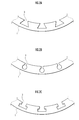
- FIG. 2A shows a guide member having a substantially trapezoidal cross section
- FIG. 2B shows a guide member having a substantially circular cross section
- FIG. 2C shows a guide member having a rectangular cross section
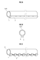
- FIG. 3A is an explanatory view showing an inner tube
- FIG. 3A shows an inner tube provided with a long engagement member
- FIG. 3B shows a cross section of FIG. 3A
- FIG. 3C shows an inner tube provided with a short engagement member. Show the tube.
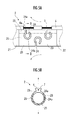
- FIG. 4A is an explanatory view showing a bent portion of the inner tube
- FIG. 4A shows a bent portion of pattern 1
- FIG. 4B is a cross-sectional view taken along line BB of FIG.
- FIG. 5A is an explanatory view showing a bent portion of the inner tube
- FIG. 5A shows a bent portion of the pattern 3
- FIG. 5B is a cross-sectional view taken along line BB of FIG. 5A.
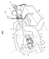
- Explanatory drawing which shows the 1st use condition of a treatment tool insertion assistance tool.
- Explanatory drawing which shows the 2nd use condition of a treatment tool insertion assistance tool.
- It is explanatory drawing which shows the deaeration prevention cap for treatment tool insertion assistance tools
- FIG. 8A is sectional drawing
- FIG. 8B is a top view.
- FIGS. 9A and 9B are explanatory views showing an inner tube including a step eliminating portion
- FIG. 9A is a perspective view
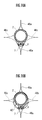
- FIG. 9B is a cross-sectional view taken along line BB in FIG. 9A. It is explanatory drawing which shows the use condition of the deaeration prevention cap for treatment tool insertion assistance tools, FIG. 10A shows the use condition in the inner tube which is not equipped with the step elimination tube, and FIG. 10B is equipped with the step elimination tube The use state with the inner tube was shown.
- the treatment instrument insertion aid 1 is a flexible cylindrical body made of a soft plastic such as polypropylene or vinyl chloride, rubber or the like, and has a plurality of inner tubes 2a, 2b, 2c (abbreviated as 2). Can be inserted). Further, the treatment instrument insertion assisting tool 1 includes a plurality of guide members 3 extending in the axial direction from the distal end side to the proximal end side on the inner peripheral surface.
- the guide member 3 is a dovetail formed on the inner wall surface of the treatment instrument insertion aid 1.
- the dovetail has a substantially trapezoidal cross-sectional shape that extends to the back side of the opening, but the opening is rectangular and the back side is substantially as shown in FIG. 2B. It may have a circular cross-sectional shape, and as shown in FIG. 2C, both the opening and the back side may have a rectangular cross-sectional shape.
- the first wire member 6 is embedded in the axial direction from the distal end side to the proximal end side between the adjacent guide members 3 and 3 on the peripheral wall surface of the treatment instrument insertion aid 1.
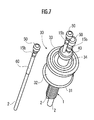
- the first wire member 6 extends rearward from the base end portion of the treatment instrument insertion assisting tool 1 and grips the first wire member operation portion 15a (see FIG. 6) provided at the base end portion.
- the treatment instrument insertion assisting tool 1 can be bent in the circumferential direction and its distal end portion can be directed in a desired direction.
- the first wire member operation section 15a temporarily fixes the operation of the first wire member 6 by temporarily fixing the operation by, for example, a ratchet mechanism (corresponding to the first wire fixture of the present invention). It is possible to maintain the state where the distal end portion of the treatment instrument insertion aid 1 is directed in a predetermined direction.
- the inner tube 2 is a flexible cylindrical body made of the soft plastic, and a treatment instrument such as an endoscope or forceps can be inserted through the inner tube 2.
- the inner tube 2 may have one channel for inserting the treatment tool, or two or more channels.
- the inner tube 2 has a hydrophilic process on the outer peripheral surface.
- the inner tube 2 includes a first inner tube 2a having a first inner diameter and a first outer diameter, a second inner diameter and a second outer diameter in order from the larger inner diameter and outer diameter. And a third inner tube 2c having a third inner diameter and a third outer diameter.
- the inner tubes 2a, 2b, 2c are color-coded from each other and can be identified.
- the inner tube 2 has an engagement member 4 that is slidable by engaging with the guide member 3 from the distal end to the proximal end of the outer peripheral surface, and a scale (not shown) for grasping the insertion depth. ) And a bendable portion 19 (see FIG. 6) that can be bent.
- Each inner tube 2 can be inserted into and removed from the treatment instrument insertion aid 1 according to the procedure.
- the engaging member 4 has a cross-sectional shape that increases in diameter as it goes from the inner diameter side to the outer diameter side of the inner tube 2, and has a substantially trapezoidal cross-sectional shape in the present embodiment, but can be engaged with the guide member 3. Any shape can be used.
- the engagement member 4 is provided from the distal end of the inner tube 2 to the proximal end, or is provided at a part of the outer peripheral surface of the inner tube 2 from the distal end to the proximal end, and at least one is provided at the distal end. Can be.
- the inner tubes 2a and 2b are provided with a long engagement member 4 continuously from the distal end to the proximal end of the inner tube 2, and the inner tube 2c.
- a plurality of short engagement members 4 are provided intermittently from the distal end to the proximal end.
- the engaging member may be provided only at the outer peripheral tip of the inner tube.
- a second wire member 7 is embedded in the engaging member 4 of the inner tube 2 in the axial direction from the distal end side to the proximal end side.
- the second wire member 7 extends rearward from the proximal end portion of the inner tube 2 and is operated by gripping the second wire member operation portion 15b (see FIG. 6) provided at the proximal end portion. can do.
- the second wire member 7 only needs to be fixed to the inner tube 2, and may be embedded in the peripheral wall portion of the inner tube 2 instead of being embedded in the engaging member 4. You may adhere
- the second wire member 7 is bent in the circumferential direction by the bending portion 19 of the inner tube 2 when the distal end portion of the tube 2 of the inner endoscope 11 or the treatment instrument 13 protrudes from the distal end of the treatment instrument insertion aid 1.
- the tip can be directed in a desired direction.
- the second wire member 7 is configured so that the inner tube 2 is not in the inner tube 2 when the inner tube 2 is accommodated in the treatment instrument insertion assisting tool 1 without the distal end portion of the inner tube 2 protruding from the distal end of the treatment instrument insertion assisting instrument 1.
- the treatment instrument insertion assisting tool 1 can be bent following the bending.
- the second wire member operation portion 15b temporarily fixes the operation of the second wire member 7 by temporarily fixing the operation by, for example, a ratchet mechanism (corresponding to the second wire fixture of the present invention).
- the tip of the inner tube 2 or the treatment instrument insertion aid 1 can be maintained in a predetermined direction.
- the bent portion 19 of the inner tube 2 may be bent in an arbitrary circumferential direction, or may be bent only in a specific direction.
- the bending part 19 that can be bent only in a specific direction can be realized by the configuration shown in FIGS.
- the inner tube 2 shown in FIGS. 4A and 4B connects the distal end side tube 21 and the proximal end side tube 22 made of a flexible resin such as polypropylene or vinyl chloride, and the tubes 21 and 22, and is more possible than the tubes 21 and 22.
- the middle tube 23 is made of a material having low flexibility (for example, stainless steel).
- the upper region and the lower region in FIG. 4B are formed so as to penetrate the outer peripheral surface along the circumferential direction, and have a width of about 1 ⁇ 4 of the peripheral length of the middle tube 23.
- Three substantially I-shaped holes 24 are provided to face each other.
- the engagement member 4 includes a hole 4a that communicates with each hole 24, and the second wire member 7 is exposed in the hole 4a.
- the inner tube 2 shown in FIGS. 4A and 4B is bent in the direction of the holed portion 25 at the bent portion 19 by the operation of the second wire member operation portion 15b, and the tip portion thereof is Although it can be directed in a specific direction (in this case, the vertical direction indicated by the arrow in FIG. 4B), it cannot be bent in the direction of the holeless portion 26, so that its tip cannot be directed in the left-right direction.
- the distal end of the inner tube 2 can be directed only in the direction desired by the practitioner.
- the bent portion 19 that bends only in a specific direction is provided with three holes 24 in the upper region in FIG. 4C on the outer peripheral surface of the middle tube 23 and four in the lower region. Two holes 24 may be provided, and the holes 24 may be arranged in a staggered manner.
- two substantially “?” Shapes are connected to the outer peripheral surface of the middle tube 23 on the upper region and the lower region in FIG. 5B by leg portions 24a.
- the leg portion 24a of the hole portion 24 is formed along the circumferential direction of the middle tube 23, and a plurality of leg portions 24a are juxtaposed in the length direction to form the hole-provided portion 25.
- a holeless portion 26 is formed between the hole 25 and the holed portion 25.
- the arc-shaped portion 24b of the hole 24 is positioned in the holeless portion 26, the leg portion 24a is not positioned.
- the inner tube 2 is not bent in the direction of the holeless portion 26 at the bent portion 19, but is bent only in the direction of the holed portion 25, and its tip portion is in a specific direction (here, FIG. 4B). (Up and down direction indicated by arrow).
- the bent portion 19 that can be bent only in a specific direction is not shown, but a tube made of a material that is less flexible than the inner tube 2 is attached to the outer peripheral side of a portion that is separated from the tip of the inner tube 2 by a predetermined distance. 4 and 5, the tube is provided with a holed portion and a holeless portion, that is, a hole formed along the circumferential direction in the circumferential wall portion of the tube. A certain portion may be provided in the length direction, and a holeless portion in which the hole portion is not formed may be provided between the holed portion and the holed portion.
- the outer tube 8 is movable on the outer peripheral surface of the treatment instrument insertion assisting tool 1 with respect to the treatment instrument insertion assisting tool 1, and is rotated around the treatment instrument insertion assisting tool 1 as an axis. It is mounted movably.
- the outer tube 8 is a flexible cylindrical body made of the soft plastic, and the outer peripheral surface is subjected to hydrophilic processing.
- the outer tube 8 is provided with two balloon members 9a and 9b that can be expanded and contracted in the middle of the outer peripheral surface so as to protrude in the outer peripheral direction.
- the balloon members 9a and 9b are connected to an air supply device. Connected air supply tube.
- a treatment instrument insertion assisting tool deaeration prevention cap (not shown) corresponding to the second degassing prevention cap of the present invention is attached to the proximal end portion of the treatment instrument insertion assisting tool 1, and each inner tube 2.
- An inner tube deaeration prevention cap (corresponding to a second deaeration prevention cap of the present invention) (not shown) is attached to the base end portion (each cap will be described later).
- the deaeration prevention cap for the treatment instrument insertion assisting tool air in the body cavity leaks from the portion where the inner tube 2 of the treatment instrument insertion assisting instrument 1 is not inserted or from the outer peripheral portion of the inserted inner tube 2. Can be prevented.
- the inner tube deaeration prevention cap it is possible to prevent air in the body cavity from leaking from the inner tube 2 in which the treatment instrument 13 is not inserted.
- each inner tube 2 an endoscope operation unit 12 for operating an endoscope 11 as a treatment tool, and treatment tools 13a and 13b (sometimes abbreviated as 13).
- This embodiment demonstrates the case where a natural opening transluminal endoscopic operation (NOTES) is performed.
- NOTES natural opening transluminal endoscopic operation
- the endoscope 11 is inserted into the first inner tube 2a, and the forceps 13a and the scalpel 13b are inserted into the second inner tube 2b and the third inner tube 2c.
- the endoscope 11, the forceps 13 a, and the scalpel 13 b do not protrude from the distal end of the treatment instrument insertion aid 1 and are embedded in the treatment tool insertion aid 1.
- the endoscope 11 protrude from the distal end of the treatment tool insertion assisting tool 1, and enter the stomach wall by the scalpel 13b.
- An opening 17 as a path is formed, and the treatment instrument insertion assisting tool 1 enters from the opening 17 outside the stomach wall.
- the stomach wall is positioned between the two balloon members 9a, 9b, and the balloon members 9a, 9 By inflating b, the stomach wall is sandwiched and fixed by the balloon members 9a and 9b, and the open state of the opening 17 is maintained.
- the treatment instrument insertion assisting tool 1 is protruded from the outer tube 8 and advanced, and if necessary, the first wire member 6 is operated by the first wire member operation section 15a and the second wire member operation section 15b. And the second wire member 7 is operated, the treatment instrument insertion assisting tool 1 is bent in the circumferential direction, and the distal end portion is directed in a desired direction, whereby the distal end portion of the treatment instrument insertion assisting tool 1 is treated on the abdominal viscera. It is made to oppose to the part 18.
- the second wire member 7 is operated by the second wire member operation portion 15b to bend the second inner tube 2b and the third inner tube 2c at the bending portion 19, thereby the inner tube 2b,
- the distal end portion of the inner tube 2c is directed in a desired direction and is opposed to the treatment target portion 18.
- the forceps 13a and the scalpel 13b are projected from the tip of the inner tube 2 to perform treatment.
- the treatment tool insertion assisting tool 1 is rotated with respect to the outer tube 8, so that the necessary treatment tool 13 is inserted.
- the tube 2 can be adjusted to a desired position, and the treatment tool 13 can be brought close to the treated portion 18.
- the forceps 13a may be exchanged with another treatment tool.
- the forceps 13a is taken out from the second inner tube 2b and the other treatment tool is inserted into the second inner tube 2b. Can be replaced with a treatment tool.
- the inner diameter of the other treatment tool is larger than the inner diameter of the second inner tube 2b, the other treatment tool cannot be inserted into the second inner tube 2b.
- the forceps 13a is pulled out together with the second inner tube 2b, and the first inner tube 2a having an inner diameter larger than the inner diameter of the second inner tube 2b is inserted. .
- the other inner tubes 2b and 2c mounted in the treatment instrument insertion assisting tool 1 are pulled out.
- the first inner tube 2a is inserted. Thereafter, by inserting another treatment instrument into the first inner tube 2a, the exchange to another treatment instrument is completed.
- the engagement member 4 of the inner tube 2 is engaged and slid on the guide member 3 extending in the axial direction from the distal end side to the proximal end side.
- the first inner tube 2a can be smoothly inserted and withdrawn in a state in which the position relative to the other inner tube 2 mounted in the treatment instrument insertion aid 1 is maintained, and a desired treatment instrument can be used. It becomes like this.
- the diameter and number of the inner tube 2 can be freely changed, and the treatment instrument 13 can be individually replaced during the treatment, and desired
- the treatment tool 13 can be used.
- the engagement members 4 of the inner tubes 2a and 2b are provided from the distal end to the proximal end, so that the inner tubes 2a and 2b are connected to the treatment instrument insertion assisting tool. 1 can be smoothly inserted and pulled out. Further, since the engaging member 4 of the inner tube 2c is provided intermittently from the distal end to the proximal end, it can be smoothly inserted and pulled out even when the entire treatment instrument insertion aid 1 is curved. Can do.
- the outer tube 8 including the balloon members 9a and 9b can be moved forward and backward with respect to the treatment instrument insertion assisting tool 1 and is rotatably mounted.
- the stomach wall is sandwiched between the balloon members 9a and 9b and the outer tube 8 is fixed, only the treatment instrument insertion assisting tool 1 is advanced or rotated so that the distal end portion of the treatment instrument insertion assisting tool 1 is treated. 18 can be closer.
- the stomach wall is sandwiched between the balloon members 9a and 9b, it is possible to prevent air, body fluid, and the like from leaking from the opening portion 17.
- the method of attaching the outer tube 8 to the treatment instrument insertion aid 1 has been described.
- the outer tube 8 can be used without being attached.
- FIG. A retractor 30 may be used as shown in FIG. As the retractor 30, for example, a retractor disclosed in Japanese Patent Application Laid-Open No. 2014-39703 can be used.
- the retractor 30 connects a ring-shaped inner fixing member 31 arranged inside the body cavity, a ring-shaped outer fixing member (not shown) arranged outside the body cavity, the inner fixing member 31 and the outer fixing member. And a tubular expansion member 32 that expands an opening (not shown) and maintains the open state, and a retractor valve cap 33 is attached to the outer fixing member.
- the retractor valve cap 33 is made of a flexible material such as polyurethane, and includes a seat member 34 that closes the opening of the outer fixing member, and is provided with a slit portion (penetrated in the thickness direction of the seat member 34).
- the treatment instrument insertion assisting tool 1 is introduced via a not-shown).
- the prevention cap 50 and the step eliminating tube 60 attached to the proximal end of the inner tube 2 will be described.
- the canopy member 41 includes a circular canopy member 41 and a mounting ring 42 for attaching the canopy member 41 to the treatment instrument insertion aid 1 in an airtight manner.
- the canopy member 41 includes two surface layer side sheet members 43a and 43b located on the front and back surfaces of the canopy member, and two inner layer side sheet members 44a and 44b stacked between the surface layer side sheet members 43a and 43b. Consists of.
- the surface layer side sheet members 43a and 43b are made of a flexible resin such as silicone rubber, polyurethane, and polyethylene, and the inner layer side sheet members 44a and 44b are stretchable and slippery with respect to the surface layer side sheet members 43a and 43b. It consists of flexible resins such as polyurethane, polyvinyl chloride, and polyethylene.
- the surface side sheet member 43a on the front side includes a first surface side slit 45a penetrating in the thickness direction at a position where the inner tube 2 can be inserted into the treatment instrument insertion aid 1. Further, the inner layer side sheet member 44a on the front surface side, the inner layer side sheet member 44b on the rear surface side, and the surface layer side sheet member 43a on the rear surface side are respectively located at positions corresponding to the first surface layer side slits 45a. A slit 46a, a second inner layer side slit 46b, and a second surface layer side slit 45b are provided.
- the first surface layer side slit 45a, the first inner layer side slit 46a, the second inner layer side slit 46b, and the second surface layer side slit 45b are formed so as to cross each other, so that the inner tube 2 is hermetically sealed. Can be introduced.
- the inner tube 2 has a base end portion and a portion introduced into the first deaeration prevention cap 40, and the outer peripheral surface of the inner tube 2 and the engaging member 4.
- a step-resolving tube 60 that fills the step with the outer peripheral surface is attached.
- the step eliminating tube 60 has a substantially elliptical outer peripheral surface, and the inner peripheral surface fills the step generated by the engagement member 4 projecting from the outer peripheral surface of the inner tube 2. It has a shape.
- the step eliminating tube 60 is filled by the step eliminating tube 60, so as shown in FIG. 10B.
- the gap generated between the first inner layer side slit 46a and the second inner layer side slit 46b and the outer peripheral surface of the step eliminating tube 60 can be reduced, and the airtightness in the body cavity can be further maintained. .
- the second wire member operation portion 15b is provided on the base end side of the step eliminating tube 60, and the inner tube deaeration prevention cap 50 is further provided on the base end side. It is installed.
- the inner tube deaeration prevention cap 50 includes an open / close valve (not shown) that can swing from the outside to the inside, and the open / close valve is introduced with the introduction of the endoscope 11 or the treatment instrument 13.
- the valve opens inward and closes the inner tube 2 by closing the valve as the endoscope 11 or the treatment instrument 13 is pulled out.
- the inner tube deaeration prevention cap 50 can prevent air in the body cavity from leaking out from the inner tube 2 in which the endoscope 11 or the treatment instrument 13 is not inserted.
- SYMBOLS 1 Treatment tool insertion auxiliary tool, 2, 2a, 2b, 2c ... Inner tube, 3 ... Guide member, 4 ... Engagement member, 6 ... First wire member, 7 ... Second wire member, 8 ... Outer tube , 9a, 9b ... balloon member, 11, 13 ... treatment instrument, 19 ... bent part, 43a, 43, 44a, 44b ... first sheet member, second sheet member, 45a, 45b, 46a, 46b ... first Slit part, second slit part, 40 ... first deaeration prevention cap, 50 ... second deaeration prevention cap, 60 ... step elimination part.
Abstract
Priority Applications (4)
| Application Number | Priority Date | Filing Date | Title |
|---|---|---|---|
| EP15737824.1A EP3095389B1 (fr) | 2014-01-15 | 2015-01-09 | Aide d'introduction d'outil chirurgical |
| SG11201605717RA SG11201605717RA (en) | 2014-01-15 | 2015-01-09 | Surgical tool insertion aid |
| JP2015557818A JP6432019B2 (ja) | 2014-01-15 | 2015-01-09 | 処置具挿入補助具 |
| US15/111,663 US10271874B2 (en) | 2014-01-15 | 2015-01-09 | Surgical tool insertion aid |
Applications Claiming Priority (2)
| Application Number | Priority Date | Filing Date | Title |
|---|---|---|---|
| JP2014005415 | 2014-01-15 | ||
| JP2014-005415 | 2014-01-15 |
Publications (1)
| Publication Number | Publication Date |
|---|---|
| WO2015107994A1 true WO2015107994A1 (fr) | 2015-07-23 |
Family
ID=53542884
Family Applications (1)
| Application Number | Title | Priority Date | Filing Date |
|---|---|---|---|
| PCT/JP2015/050500 WO2015107994A1 (fr) | 2014-01-15 | 2015-01-09 | Aide d'introduction d'outil chirurgical |
Country Status (7)
| Country | Link |
|---|---|
| US (1) | US10271874B2 (fr) |
| EP (1) | EP3095389B1 (fr) |
| JP (1) | JP6432019B2 (fr) |
| MY (1) | MY178031A (fr) |
| SG (1) | SG11201605717RA (fr) |
| TW (1) | TWI641354B (fr) |
| WO (1) | WO2015107994A1 (fr) |
Cited By (5)
| Publication number | Priority date | Publication date | Assignee | Title |
|---|---|---|---|---|
| WO2017119108A1 (fr) * | 2016-01-07 | 2017-07-13 | 学校法人慶應義塾 | Dispositif de traitement endoscope |
| JP2018078947A (ja) * | 2016-11-14 | 2018-05-24 | 株式会社トップ | 内視鏡用オーバーチューブ |
| JPWO2018070042A1 (ja) * | 2016-10-14 | 2019-08-15 | 株式会社メディカロイド | 医療用器具および手術システム |
| KR20210048863A (ko) * | 2019-10-24 | 2021-05-04 | 인제대학교 산학협력단 | 폐냉동생검을 위한 지혈용 삽입관 유닛 |
| US11369442B2 (en) | 2016-10-14 | 2022-06-28 | Medicaroid Corporation | Surgical system |
Families Citing this family (3)
| Publication number | Priority date | Publication date | Assignee | Title |
|---|---|---|---|---|
| US10463245B2 (en) * | 2015-12-21 | 2019-11-05 | Snug Harbor Orthopedics, LLC | Method of using cannula for surgical procedure |
| JPWO2018021582A1 (ja) * | 2017-08-31 | 2020-10-15 | 富士フイルム株式会社 | 外科手術システム |
| KR102614596B1 (ko) * | 2020-07-27 | 2023-12-18 | 유펙스메드 주식회사 | 복수개 처치구 병용을 위한 멀티 루멘 구조의 의료용 토출 기구 |
Citations (6)
| Publication number | Priority date | Publication date | Assignee | Title |
|---|---|---|---|---|
| JPS62167531A (ja) | 1985-09-30 | 1987-07-23 | オリンパス光学工業株式会社 | マルチル−メンチユ−ブ内視鏡 |
| JP2007511247A (ja) * | 2003-05-19 | 2007-05-10 | ユーエスジーアイ メディカル, インコーポレイテッド | 管腔ツール展開システム |
| WO2007063904A1 (fr) * | 2005-12-01 | 2007-06-07 | Olympus Medical Systems Corp. | Long membre de guidage médical et long appareil médical |
| JP2011515127A (ja) * | 2008-03-14 | 2011-05-19 | アクセス サイエンティフィック、インク. | アクセス装置 |
| JP2011245017A (ja) * | 2010-05-26 | 2011-12-08 | Haruhiro Inoue | 外科手術用開創器具のバルブキャップ |
| JP2014039703A (ja) | 2012-08-23 | 2014-03-06 | Haruhiro Inoue | 開創器用バルブキャップ |
Family Cites Families (11)
| Publication number | Priority date | Publication date | Assignee | Title |
|---|---|---|---|---|
| JPH10192226A (ja) * | 1997-01-17 | 1998-07-28 | Olympus Optical Co Ltd | 器具挿入補助具 |
| US7637905B2 (en) * | 2003-01-15 | 2009-12-29 | Usgi Medical, Inc. | Endoluminal tool deployment system |
| US20080249504A1 (en) * | 2007-04-06 | 2008-10-09 | Lattouf Omar M | Instrument port |
| US7029435B2 (en) | 2003-10-16 | 2006-04-18 | Granit Medical Innovation, Llc | Endoscope having multiple working segments |
| JP2005296412A (ja) | 2004-04-13 | 2005-10-27 | Olympus Corp | 内視鏡治療装置 |
| US7951117B2 (en) * | 2008-06-25 | 2011-05-31 | Tyco Healthcare Group Lp | Multi-lumen access port |
| AU2008243031B2 (en) * | 2007-04-17 | 2014-04-24 | Covidien Lp | Rigidizable endoluminal access device |
| WO2008131300A2 (fr) | 2007-04-18 | 2008-10-30 | Access Scientific, Inc. | Dispositif d'accès |
| US20110112434A1 (en) | 2009-11-06 | 2011-05-12 | Ethicon Endo-Surgery, Inc. | Kits and procedures for natural orifice translumenal endoscopic surgery |
| TWI434668B (zh) * | 2011-02-10 | 2014-04-21 | Metal Ind Res & Dev Ct | 具有模組化骨髓內釘之醫療器材 |
| JP5498422B2 (ja) * | 2011-03-28 | 2014-05-21 | 富士フイルム株式会社 | 内視鏡用挿入補助具 |
-
2015
- 2015-01-09 EP EP15737824.1A patent/EP3095389B1/fr active Active
- 2015-01-09 SG SG11201605717RA patent/SG11201605717RA/en unknown
- 2015-01-09 MY MYPI2016702561A patent/MY178031A/en unknown
- 2015-01-09 JP JP2015557818A patent/JP6432019B2/ja active Active
- 2015-01-09 US US15/111,663 patent/US10271874B2/en active Active
- 2015-01-09 WO PCT/JP2015/050500 patent/WO2015107994A1/fr active Application Filing
- 2015-01-15 TW TW104101316A patent/TWI641354B/zh active
Patent Citations (6)
| Publication number | Priority date | Publication date | Assignee | Title |
|---|---|---|---|---|
| JPS62167531A (ja) | 1985-09-30 | 1987-07-23 | オリンパス光学工業株式会社 | マルチル−メンチユ−ブ内視鏡 |
| JP2007511247A (ja) * | 2003-05-19 | 2007-05-10 | ユーエスジーアイ メディカル, インコーポレイテッド | 管腔ツール展開システム |
| WO2007063904A1 (fr) * | 2005-12-01 | 2007-06-07 | Olympus Medical Systems Corp. | Long membre de guidage médical et long appareil médical |
| JP2011515127A (ja) * | 2008-03-14 | 2011-05-19 | アクセス サイエンティフィック、インク. | アクセス装置 |
| JP2011245017A (ja) * | 2010-05-26 | 2011-12-08 | Haruhiro Inoue | 外科手術用開創器具のバルブキャップ |
| JP2014039703A (ja) | 2012-08-23 | 2014-03-06 | Haruhiro Inoue | 開創器用バルブキャップ |
Non-Patent Citations (1)
| Title |
|---|
| See also references of EP3095389A4 |
Cited By (7)
| Publication number | Priority date | Publication date | Assignee | Title |
|---|---|---|---|---|
| WO2017119108A1 (fr) * | 2016-01-07 | 2017-07-13 | 学校法人慶應義塾 | Dispositif de traitement endoscope |
| JPWO2017119108A1 (ja) * | 2016-01-07 | 2018-11-01 | 学校法人慶應義塾 | 内視鏡治療装置 |
| JPWO2018070042A1 (ja) * | 2016-10-14 | 2019-08-15 | 株式会社メディカロイド | 医療用器具および手術システム |
| US11369442B2 (en) | 2016-10-14 | 2022-06-28 | Medicaroid Corporation | Surgical system |
| JP2018078947A (ja) * | 2016-11-14 | 2018-05-24 | 株式会社トップ | 内視鏡用オーバーチューブ |
| KR20210048863A (ko) * | 2019-10-24 | 2021-05-04 | 인제대학교 산학협력단 | 폐냉동생검을 위한 지혈용 삽입관 유닛 |
| KR102326469B1 (ko) | 2019-10-24 | 2021-11-12 | 인제대학교 산학협력단 | 폐냉동생검을 위한 지혈용 삽입관 유닛 |
Also Published As
| Publication number | Publication date |
|---|---|
| TW201544066A (zh) | 2015-12-01 |
| JP6432019B2 (ja) | 2018-12-12 |
| SG11201605717RA (en) | 2016-08-30 |
| JPWO2015107994A1 (ja) | 2017-03-23 |
| EP3095389B1 (fr) | 2018-12-19 |
| TWI641354B (zh) | 2018-11-21 |
| US20160331402A1 (en) | 2016-11-17 |
| EP3095389A1 (fr) | 2016-11-23 |
| MY178031A (en) | 2020-09-29 |
| EP3095389A4 (fr) | 2017-10-18 |
| US10271874B2 (en) | 2019-04-30 |
Similar Documents
| Publication | Publication Date | Title |
|---|---|---|
| JP6432019B2 (ja) | 処置具挿入補助具 | |
| US8262563B2 (en) | Endoscopic translumenal articulatable steerable overtube | |
| US8337394B2 (en) | Overtube with expandable tip | |
| US9226772B2 (en) | Surgical device | |
| US8287447B2 (en) | Outer tube for natural orifice surgery | |
| JP4995136B2 (ja) | オーバーチューブ及び処置システム | |
| JP5448637B2 (ja) | 挿入経路確保装置 | |
| US20100010298A1 (en) | Endoscopic translumenal flexible overtube | |
| JP5647780B2 (ja) | 処置用オーバーチューブ及び処置システム | |
| US20090062614A1 (en) | Closures for outer tube for natural orifice surgery | |
| KR101615448B1 (ko) | 흉부용 카테터 | |
| WO2016143142A1 (fr) | Aide d'introduction d'instrument de traitement | |
| CN111629643A (zh) | 内窥镜外套管和内窥镜 | |
| JP2008148887A (ja) | 生体管路内処置デバイス | |
| US8012086B2 (en) | Sterile transcolonic access device | |
| WO2017119108A1 (fr) | Dispositif de traitement endoscope | |
| WO2010009070A1 (fr) | Surtube endoscopique transluminal flexible, articulable et guidable | |
| WO2016143143A1 (fr) | Auxiliaire d'insertion d'instrument de traitement | |
| RU149055U1 (ru) | Направляющее устройство для холедохоскопа | |
| US20080147020A1 (en) | Tear away colonic sheath | |
| WO2021059943A1 (fr) | Cathéter à ballonnet | |
| JP5469115B2 (ja) | ダブルオーバーチューブ | |
| WO2021153090A1 (fr) | Dispositif de support de ballonnet | |
| JP2021049256A (ja) | バルーンカテーテル | |
| JPWO2018207895A1 (ja) | 器具保持具および医療用器具供給具 |
Legal Events
| Date | Code | Title | Description |
|---|---|---|---|
| 121 | Ep: the epo has been informed by wipo that ep was designated in this application |
Ref document number: 15737824 Country of ref document: EP Kind code of ref document: A1 |
|
| DPE1 | Request for preliminary examination filed after expiration of 19th month from priority date (pct application filed from 20040101) | ||
| ENP | Entry into the national phase |
Ref document number: 2015557818 Country of ref document: JP Kind code of ref document: A |
|
| WWE | Wipo information: entry into national phase |
Ref document number: 15111663 Country of ref document: US |
|
| NENP | Non-entry into the national phase |
Ref country code: DE |
|
| REEP | Request for entry into the european phase |
Ref document number: 2015737824 Country of ref document: EP |
|
| WWE | Wipo information: entry into national phase |
Ref document number: 2015737824 Country of ref document: EP |