WO2015104901A1 - Outil de coupe de paroi vaginale - Google Patents
Outil de coupe de paroi vaginale Download PDFInfo
- Publication number
- WO2015104901A1 WO2015104901A1 PCT/JP2014/080353 JP2014080353W WO2015104901A1 WO 2015104901 A1 WO2015104901 A1 WO 2015104901A1 JP 2014080353 W JP2014080353 W JP 2014080353W WO 2015104901 A1 WO2015104901 A1 WO 2015104901A1
- Authority
- WO
- WIPO (PCT)
- Prior art keywords
- vaginal
- cylinder member
- incision
- vaginal wall
- vaginal canal
- Prior art date
Links
Images


Classifications
-
- A—HUMAN NECESSITIES
- A61—MEDICAL OR VETERINARY SCIENCE; HYGIENE
- A61B—DIAGNOSIS; SURGERY; IDENTIFICATION
- A61B18/00—Surgical instruments, devices or methods for transferring non-mechanical forms of energy to or from the body
- A61B18/04—Surgical instruments, devices or methods for transferring non-mechanical forms of energy to or from the body by heating
- A61B18/12—Surgical instruments, devices or methods for transferring non-mechanical forms of energy to or from the body by heating by passing a current through the tissue to be heated, e.g. high-frequency current
- A61B18/14—Probes or electrodes therefor
- A61B18/1485—Probes or electrodes therefor having a short rigid shaft for accessing the inner body through natural openings
-
- A—HUMAN NECESSITIES
- A61—MEDICAL OR VETERINARY SCIENCE; HYGIENE
- A61B—DIAGNOSIS; SURGERY; IDENTIFICATION
- A61B17/00—Surgical instruments, devices or methods, e.g. tourniquets
- A61B17/42—Gynaecological or obstetrical instruments or methods
-
- A—HUMAN NECESSITIES
- A61—MEDICAL OR VETERINARY SCIENCE; HYGIENE
- A61B—DIAGNOSIS; SURGERY; IDENTIFICATION
- A61B17/00—Surgical instruments, devices or methods, e.g. tourniquets
- A61B17/42—Gynaecological or obstetrical instruments or methods
- A61B2017/4216—Operations on uterus, e.g. endometrium
- A61B2017/4225—Cervix uteri
-
- A—HUMAN NECESSITIES
- A61—MEDICAL OR VETERINARY SCIENCE; HYGIENE
- A61B—DIAGNOSIS; SURGERY; IDENTIFICATION
- A61B18/00—Surgical instruments, devices or methods for transferring non-mechanical forms of energy to or from the body
- A61B2018/00053—Mechanical features of the instrument of device
- A61B2018/00059—Material properties
- A61B2018/00071—Electrical conductivity
- A61B2018/00077—Electrical conductivity high, i.e. electrically conducting
-
- A—HUMAN NECESSITIES
- A61—MEDICAL OR VETERINARY SCIENCE; HYGIENE
- A61B—DIAGNOSIS; SURGERY; IDENTIFICATION
- A61B18/00—Surgical instruments, devices or methods for transferring non-mechanical forms of energy to or from the body
- A61B2018/00053—Mechanical features of the instrument of device
- A61B2018/00059—Material properties
- A61B2018/00071—Electrical conductivity
- A61B2018/00083—Electrical conductivity low, i.e. electrically insulating
-
- A—HUMAN NECESSITIES
- A61—MEDICAL OR VETERINARY SCIENCE; HYGIENE
- A61B—DIAGNOSIS; SURGERY; IDENTIFICATION
- A61B18/00—Surgical instruments, devices or methods for transferring non-mechanical forms of energy to or from the body
- A61B2018/00053—Mechanical features of the instrument of device
- A61B2018/00184—Moving parts
- A61B2018/00196—Moving parts reciprocating lengthwise
-
- A—HUMAN NECESSITIES
- A61—MEDICAL OR VETERINARY SCIENCE; HYGIENE
- A61B—DIAGNOSIS; SURGERY; IDENTIFICATION
- A61B18/00—Surgical instruments, devices or methods for transferring non-mechanical forms of energy to or from the body
- A61B2018/00053—Mechanical features of the instrument of device
- A61B2018/00184—Moving parts
- A61B2018/00202—Moving parts rotating
- A61B2018/00208—Moving parts rotating actively driven, e.g. by a motor
-
- A—HUMAN NECESSITIES
- A61—MEDICAL OR VETERINARY SCIENCE; HYGIENE
- A61B—DIAGNOSIS; SURGERY; IDENTIFICATION
- A61B18/00—Surgical instruments, devices or methods for transferring non-mechanical forms of energy to or from the body
- A61B2018/00053—Mechanical features of the instrument of device
- A61B2018/00273—Anchoring means for temporary attachment of a device to tissue
- A61B2018/00279—Anchoring means for temporary attachment of a device to tissue deployable
-
- A—HUMAN NECESSITIES
- A61—MEDICAL OR VETERINARY SCIENCE; HYGIENE
- A61B—DIAGNOSIS; SURGERY; IDENTIFICATION
- A61B18/00—Surgical instruments, devices or methods for transferring non-mechanical forms of energy to or from the body
- A61B2018/00315—Surgical instruments, devices or methods for transferring non-mechanical forms of energy to or from the body for treatment of particular body parts
- A61B2018/00559—Female reproductive organs
-
- A—HUMAN NECESSITIES
- A61—MEDICAL OR VETERINARY SCIENCE; HYGIENE
- A61B—DIAGNOSIS; SURGERY; IDENTIFICATION
- A61B18/00—Surgical instruments, devices or methods for transferring non-mechanical forms of energy to or from the body
- A61B2018/00571—Surgical instruments, devices or methods for transferring non-mechanical forms of energy to or from the body for achieving a particular surgical effect
- A61B2018/00601—Cutting
-
- A—HUMAN NECESSITIES
- A61—MEDICAL OR VETERINARY SCIENCE; HYGIENE
- A61B—DIAGNOSIS; SURGERY; IDENTIFICATION
- A61B18/00—Surgical instruments, devices or methods for transferring non-mechanical forms of energy to or from the body
- A61B18/04—Surgical instruments, devices or methods for transferring non-mechanical forms of energy to or from the body by heating
- A61B18/12—Surgical instruments, devices or methods for transferring non-mechanical forms of energy to or from the body by heating by passing a current through the tissue to be heated, e.g. high-frequency current
- A61B18/14—Probes or electrodes therefor
- A61B2018/1405—Electrodes having a specific shape
- A61B2018/1425—Needle
-
- A—HUMAN NECESSITIES
- A61—MEDICAL OR VETERINARY SCIENCE; HYGIENE
- A61B—DIAGNOSIS; SURGERY; IDENTIFICATION
- A61B18/00—Surgical instruments, devices or methods for transferring non-mechanical forms of energy to or from the body
- A61B18/04—Surgical instruments, devices or methods for transferring non-mechanical forms of energy to or from the body by heating
- A61B18/12—Surgical instruments, devices or methods for transferring non-mechanical forms of energy to or from the body by heating by passing a current through the tissue to be heated, e.g. high-frequency current
- A61B18/14—Probes or electrodes therefor
- A61B2018/1405—Electrodes having a specific shape
- A61B2018/144—Wire
-
- A—HUMAN NECESSITIES
- A61—MEDICAL OR VETERINARY SCIENCE; HYGIENE
- A61B—DIAGNOSIS; SURGERY; IDENTIFICATION
- A61B18/00—Surgical instruments, devices or methods for transferring non-mechanical forms of energy to or from the body
- A61B18/04—Surgical instruments, devices or methods for transferring non-mechanical forms of energy to or from the body by heating
- A61B18/12—Surgical instruments, devices or methods for transferring non-mechanical forms of energy to or from the body by heating by passing a current through the tissue to be heated, e.g. high-frequency current
- A61B18/14—Probes or electrodes therefor
- A61B2018/1475—Electrodes retractable in or deployable from a housing
Definitions
- the present invention relates to a vaginal wall incision tool.
- This application claims priority based on Japanese Patent Application No. 2014-003132 filed in Japan on January 10, 2014, the contents of which are incorporated herein by reference.
- total laparoscopic hysterectomy and laparoscopic upper cervical excision are known as techniques for excising the uterus.
- Total laparoscopic hysterectomy and laparoscopic upper cervicalectomy are procedures that require the use of a laparoscope, a uterine manipulator, and an ablation instrument. That is, in total laparoscopic hysterectomy and laparoscopic upper cervical enucleation, the incision target site is confirmed using a laparoscope, and the cutting line is adjusted using a uterine manipulator. Therefore, it is necessary that the operation of making an incision using a cutting device is performed in a coordinated manner.
- the laparoscope and the cutting device are inserted into the abdominal cavity through the abdominal wall through the trocar.
- the operation of the detachment device performed in the abdominal cavity is from the direction intersecting the normal detachment line without tilting the uterus to the detachment line. It is necessary to approach. For this reason, unless the uterus is tilted using the uterine manipulator, it is difficult to cut it straight along the cutting line.
- a coordinated operation of the uterine manipulator, the cutting instrument, and the laparoscope is required.
- Patent Document 1 discloses a high-frequency resection tool that can be combined with an endoscope.
- Patent Document 2 discloses a treatment endoscope that can be combined with a high-frequency snare that incises tissue by energizing a high-frequency current.
- the treatment endoscope disclosed in Patent Document 2 has an engagement portion that can hook a loop portion of a high-frequency snare at a distal end, and is a wire-like shape that is located proximal to the loop portion of the high-frequency snare. Using this part as an incision electrode, the entire wall of the living body can be excised.
- Patent Documents 1 and 2 When applying the techniques disclosed in Patent Documents 1 and 2 in total laparoscopic total hysterectomy and laparoscopic upper cervical excision, it is necessary to coordinate multiple instruments in the abdominal cavity. It is difficult to accurately cut tissue along the line, and it is difficult to reduce the time required for the cutting operation.
- the present invention has been made in view of the above-described circumstances, and an object of the present invention is to provide a vaginal wall incision tool capable of accurately cutting a living tissue along a cutting line in a short time.
- a vaginal wall incision tool includes a main body part that can be inserted into a vaginal canal, and a distal part of the main body part in a state where the main body part is inserted into the vaginal duct. Projecting in a direction intersecting the center line of the vaginal canal and penetrating into the vaginal canal, and being disposed at an incision part capable of incising the vaginal duct and a proximal portion of the body part, An operation part capable of adjusting the protrusion amount of the part, and the main body part is inserted into the exterior part that can come into contact with the inner wall of the vaginal canal and has a predetermined amount with respect to the exterior part.
- the exterior part is airtight between the cylindrical outer cylinder member and the outer cylinder member and the interior part. And an airtight valve that closes.
- the exterior portion projects from the outer peripheral surface of the exterior portion toward the radially outer side of the exterior portion, and the vagina You may provide the latching
- the locking portion may include a plurality of anchors that can be locked to the inner wall of the vaginal canal.
- the operation portion includes a substantially rod-shaped shaft body, and a sawtooth portion provided on an outer surface of the shaft body.
- the slider may include a slider attached to the shaft body, and a protrusion provided on the slider and engageable with a plurality of protrusions constituting the sawtooth portion.
- the interior portion is formed in a cup shape whose diameter is gradually increased toward the distal side, and an inner surface is formed.
- the interior portion is formed in a rod shape that is coaxial with the rotation center of the interior portion and projects to the distal side.
- the positioning member may be provided.
- the incision portion is disposed in the conductive member having conductivity and the operation portion, and is electrically connected to the conductive member.
- a connector for supplying a high-frequency current to the conductive member, and the interior portion includes a contact portion having a surface capable of contacting the uterine vagina, and a distal end portion of the conductive member.
- a guide hole that can be moved back and forth in a direction intersecting the center line of the vaginal canal, and the guide hole allows the conductive member to be placed in a state in which the contact portion is in contact with the uterine vagina. It may be possible to guide toward the boundary between the cervix and the vaginal canal.
- the biological tissue can be separated along the separation line with high accuracy in a short time.
- FIG. 1 is an overall view showing a vaginal wall incision device according to a first embodiment of the present invention. It is a fragmentary sectional view of the vaginal wall incision tool concerning a 1st embodiment of the present invention. It is sectional drawing of the operation part in the vaginal wall incision tool concerning 1st Embodiment of this invention. It is a figure for demonstrating the effect
- FIG. 1 It is a perspective view which shows the intermediate
- FIG. 19 is a view for explaining a procedure using the vaginal wall incising tool according to the third embodiment of the present invention, and is a cross-sectional view taken along the line BB of FIG. It is a figure for demonstrating the procedure using the vaginal wall incision tool concerning 3rd Embodiment of this invention.
- FIG. 19 is a view for explaining a procedure using the vaginal wall incising tool according to the third embodiment of the present invention, and is a cross-sectional view taken along the line BB of FIG. It is a figure for demonstrating the procedure using the vaginal wall incision tool concerning 3rd Embodiment of this invention.
- FIG. 21 is a view for explaining a procedure using the vaginal wall incising tool according to the third embodiment of the present invention, and is a cross-sectional view taken along the line CC of FIG. 20. It is a figure for demonstrating the procedure using the vaginal wall incision tool concerning 3rd Embodiment of this invention.
- FIG. 23 is a view for explaining a procedure using the vaginal wall incising tool according to the third embodiment of the present invention, and is a cross-sectional view taken along the line DD of FIG. It is a figure for demonstrating the procedure using the vaginal wall incision tool concerning 3rd Embodiment of this invention.
- FIG. 23 is a view for explaining a procedure using the vaginal wall incising tool according to the third embodiment of the present invention, and is a cross-sectional view taken along the line DD of FIG. It is a figure for demonstrating the procedure using the vaginal wall incision tool concerning 3rd Embodiment of this invention.
- FIG. 25 is a view for explaining a procedure using the vaginal wall incising tool according to the third embodiment of the present invention, and is a cross-sectional view taken along the line EE of FIG. 24.
- It is a general view which shows the vaginal wall incision tool which concerns on 4th Embodiment of this invention.
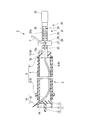
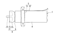
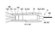
- FIG. 1 is an overall view showing a vaginal wall incising instrument 1 according to this embodiment.
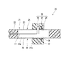
- FIG. 2 is a partial cross-sectional view of the vaginal wall incising instrument 1 according to this embodiment.
- FIG. 3 is a cross-sectional view of the operation unit 20 in the vaginal wall incising instrument 1 according to the present embodiment.
- the vaginal wall incision tool 1 shown in FIG. 1 is a medical instrument that can be used for the purpose of separating the uterus from the vagina in total laparoscopic hysterectomy and laparoscopic upper cervical excision. As shown in FIG. 1, the vaginal wall incision tool 1 has a substantially rod-like shape as a whole.
- the vaginal wall incision tool 1 includes a main body part 2, an incision part 16, and an operation part 20.
- the main body 2 has a substantially rod-like shape as a whole.
- the main body 2 can be inserted into the vaginal canal from the distal side.
- the main body 2 includes an exterior part 3 and an interior part 8.
- the exterior part 3 constitutes the outermost layer in the main body part 2.
- the exterior part 3 includes an outer cylinder member 4, a locking part 5, and an airtight valve 7.
- the outer cylinder member 4 has a cylindrical shape having an outer dimension that can be inserted into the vaginal canal.
- the outer cylinder member 4 is hard or slightly elastic.
- the outer cylinder member 4 is formed of resin or the like.
- examples of the material of the outer cylinder member 4 include a fluorine-based resin (for example, polytetrafluoroethylene), a nylon-based resin (for example, nylon), and an olefin-based resin (for example, polyethylene and polypropylene).
- the outer peripheral surface of the outer cylinder member 4 has a smooth curved surface that does not damage the mucous membrane.
- the locking part 5 has an annular member 6 fixed to the outer peripheral surface of the outer cylinder member 4.
- the annular member 6 is disposed in the vicinity of the distal end of the outer cylinder member 4.
- the annular member 6 extends in the circumferential direction of the outer cylinder member 4 on the outer peripheral surface of the outer cylinder member 4.
- the annular member 6 and the outer cylinder member 4 are fixed by adhesion, for example.
- the annular member 6 and the outer cylinder member 4 may be integrally formed.
- the annular member 6 projects from the outer peripheral surface of the outer cylinder member 4 to the outer side in the radial direction of the outer cylinder member 4.
- the outer peripheral surface of the annular member 6 has a smooth curved surface so as not to damage the mucous membrane.
- the annular member 6 acts to airtightly seal the gap between the outer tube member 4 and the vagina wall when the vaginal wall incising tool 1 is used.
- the annular member 6 acts to make it difficult for the vagina wall to move with respect to the outer cylinder member 4 when the vagina wall is incised.
- the airtight valve 7 is a valve for airtightly closing the outer cylinder member 4 and the interior portion 8.
- the airtight valve 7 is fixed to the opening at the proximal end of the outer cylinder member 4.
- the airtight valve 7 has an annular shape having a hole 7a.
- the interior portion 8 can be inserted into the hole 7 a formed in the airtight valve 7.
- the airtight valve 7 is in close contact with the connecting member 10 so as to be slidable in an airtight state in a state where a connecting member 10 of the interior portion 8 described later is inserted into the hole 7a.
- the airtight valve 7 has elasticity. Further, the center line of the opening of the hole 7 a of the airtight valve 7 coincides with the center line of the outer cylinder member 4.
- the airtight valve 7 supports the connecting member 10 so that the connecting member 10 can rotate about the center line of the outer cylinder member 4 as a rotation center.
- the material of the airtight valve 7 is not particularly limited as long as it has elasticity.
- the airtight valve 7 is formed using silicone or urethane as a material.
- the interior portion 8 can rotate around the center line of the outer cylinder member 4 as the center of rotation inside the outer cylinder member 4.
- the interior portion 8 includes an inner cylinder member 9, a connecting member 10, and a contact portion 11.
- the inner cylinder member 9 is a cylindrical member disposed inside the outer cylinder member 4.
- the outer diameter dimension of the inner cylinder member 9 is slightly smaller than the inner diameter dimension of the outer cylinder member 4.
- the center line of the inner cylinder member 9 is substantially coaxial with the center line of the outer cylinder member 4.
- the inner cylinder member 9 has such a hardness that it can transmit the amount of force for rotating the operation section 20 around the center line of the outer cylinder member 4 to the contact section 11.
- the connecting member 10 connects the distal end of a shaft body 22 of the shaft portion 21 described later in the operation unit 20 and the proximal end of the inner cylinder member 9.
- the connecting member 10 has a substantially cylindrical shape having a hole 10a.
- the outer peripheral surface of the connecting member 10 is in close contact with the inner surface of the hole 7 a of the airtight valve 7.
- the distal end of the shaft 22 of the operation unit 20 is inserted into the hole 10a formed in the connecting member 10.
- the connecting member 10 is fixed to the shaft body 22 by adhesion, for example.
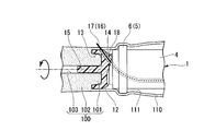
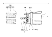
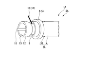
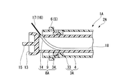
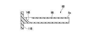
- the abutting portion 11 is disposed at the distal portion of the interior portion 8.
- the contact portion 11 can contact the uterine vagina when the vaginal wall incision tool 1 is used.
- the contact portion 11 of the present embodiment includes a cup-shaped member 12 and a positioning member 15.
- the cup-shaped member 12 has a cup shape that is gradually expanded in diameter toward the distal side.
- the positioning member 15 protrudes from the inner surface of the cup-shaped member 12.
- the cup-shaped member 12 is fixed to the distal end of the inner cylinder member 9.
- the cup-shaped member 12 has a concave surface portion 13 and a guide hole 14.
- the concave surface portion 13 can contact the cervix.
- the guide hole 14 communicates with the inside of the inner cylinder member 9 and is formed long in a direction inclined with respect to the center line of the inner cylinder member 9.
- a distal end of a cylindrical insulating member 18 to be described later in the incision 16 is fixed.
- the guide hole 14 restricts the advancing / retreating direction of the conductive member 17 that can protrude from the insulating member 18 of the incision 16 to a predetermined direction inclined with respect to the center line of the inner cylinder member 9.
- the guide hole 14 is arranged so that the distal end of the conductive member 17 moves obliquely outward in the radial direction of the inner cylinder member 9 when the conductive member 17 is moved to the distal side of the inner cylinder member 9. The advance / retreat of the conductive member 17 is guided.
- the inclination angle of the center line of the guide hole 14 with respect to the center line of the inner cylinder member 9 is such that the distal end of the conductive member 17 does not contact the cervix or uterine body part when the vaginal wall incision tool 1 is used.
- the angle is set to be separated from the body part.
- the positioning member 15 is a rod-like member protruding from the bottom of the concave surface portion 13 of the cup-like member 12 toward the distal side.
- the positioning member 15 extends coaxially with the center line of the inner cylinder member 9.
- the protruding length of the positioning member 15 from the concave surface portion 13 is such that at least the distal end of the positioning member 15 is inserted into the uterine ostium while the uterine vagina is in contact with the concave surface portion 13 of the cup-shaped member 12.
- the positioning member 15 can connect the uterine ostium 103 and the abutment portion 11 so that the abutment portion 11 can rotate around the uterine ostium 103 as a rotation center.
- the conductive member 17 disposed in the guide hole 14 of the cup-shaped member 12 with the uterine ostium 103 as the rotation center. Is rotatable.
- the incision 16 has a conductive member 17 and an insulating member 18.
- the conductive member 17 is formed using a conductor as a material.
- a conductive member 17 is inserted into the insulating member 18 so as to be able to advance and retract.
- the conductive member 17 is a conductor such as a metal and has elasticity so that it is linear in a state where no external force is applied at least in the distal portion.
- the conductive member 17 is formed of an elastic wire having a restoring force that is linear when no external force is applied.
- the distal end of the conductive member 17 is supported via an insulating member 18 by a guide hole 14 formed in the cup-shaped member 12.
- the proximal end of the conductive member 17 is fixed to a slider 26 of the operation unit 20 described later.
- the proximal end of the conductive member 17 is fixed to a connector 29 described later provided on the slider 26.
- the conductive member 17 and the connector 29 can be electrically connected.
- An intermediate portion of the conductive member 17 is disposed inside the inner cylinder member 9.
- the insulating member 18 has a cylindrical shape that covers the conductive member 17.
- the distal end of the insulating member 18 is fixed to the inner surface of the guide hole 14 of the cup-shaped member 12.
- the proximal end of the insulating member 18 is fixed to the distal end of the shaft body 22 of the shaft portion 21 of the operation unit 20.
- the operation unit 20 is provided for performing an advance / retreat operation of the conductive member 17 and a rotation operation for rotating the entire vaginal wall incising tool 1 around the center line of the outer cylinder member 4 as a rotation center.
- the operation unit 20 includes a shaft portion 21 and a slider 26.
- the shaft portion 21 extends proximally from the proximal end of the connecting member 10.
- the slider 26 is attached to the shaft portion 21.
- the shaft portion 21 has a substantially bar shape that can be gripped by the operator.
- the shaft portion 21 includes a shaft body 22, a ring 23, and a sawtooth portion 24.
- the shaft body 22 has a substantially cylindrical shape.
- the ring 23 is formed at the proximal end of the shaft body 22.
- the serrated portions 24 are arranged in the longitudinal direction of the shaft body 22 on the outer surface of the shaft body 22.
- the shaft body 22 has a substantially cylindrical shape in which the proximal portion of the conductive member 17 is inserted.
- the shaft body 22 is provided with a through hole 22 a for connecting the shaft body 22 and the slider 26 so as to extend in the longitudinal direction of the shaft body 22.
- the distal end of the shaft body 22 is inserted into the hole 10 a of the connecting member 10.
- the distal end of the shaft body 22 and the hole 10a of the connecting member 10 are fixed by, for example, adhesion.
- the center line of the shaft body 22 is set coaxially with the center line of the inner cylinder member 9. For this reason, by rotating the shaft body 22 around the center line of the shaft body 22, the abutting portion 11 fixed to the inner cylinder member 9 and the inner cylinder member 9 rotates the center line of the inner cylinder member 9 as the center of rotation. Rotate as
- the ring 23 has an annular shape whose center line extends in a direction orthogonal to the center line of the shaft body 22 at the proximal end of the shaft body 22.
- the ring 23 has an internal dimension that allows the operator's finger to pass through.
- the outer diameter of the ring 23 is larger than the diameter of the shaft body 22.
- the ring 23 can be pinched with an operator's finger when performing an operation of rotating the shaft body 22 around the center line of the shaft body 22 as a rotation center.
- the sawtooth portion 24 is composed of a plurality of protrusions 25 protruding outward in the radial direction of the shaft body 22 on the outer surface of the shaft body 22.
- the serrated portion 24 is integrally formed with the shaft body 22.
- the plurality of protrusions 25 constituting the serrated portion 24 are arranged along the opening end of the through hole 22 a formed in the shaft body 22 in the outer surface of the shaft body 22.
- the serrated portions 24 are arranged at two locations so as to protrude in opposite directions at positions facing each other across the central axis of the shaft body 22.
- a plurality of protrusions 25 constituting the sawtooth portion 24 engage with a convex portion 28 of a slider 26 described later.
- the convex portion 28 is positioned between a pair of adjacent projections 25, whereby the position of the slider 26 in the sawtooth portion 24 can be maintained.
- the slider 26 is applied to the shaft body 22 in the longitudinal direction of the shaft body 22 at the sawtooth portion 24. It can be moved.
- the slider 26 is a member that can move back and forth in the longitudinal direction of the shaft body 22 with respect to the shaft body 22.
- the slider 26 is provided to move the conductive member 17 forward and backward with respect to the insulating member 18.
- the slider 26 includes a cylindrical body 27, a convex portion 28, and a connector 29.
- the shaft body 22 is inserted through the cylindrical body 27.
- the convex portion 28 is provided on the inner surface of the cylindrical body 27.
- the connector 29 is fixed to the cylindrical body 27 and is fixed to the proximal end of the conductive member 17.
- the cylindrical body 27 has a through hole 27 a slightly larger than the outer diameter of the shaft body 22.
- the inner diameter of the cylindrical body 27 is smaller than the outer diameter of the ring 23 shown in FIG.
- the cylindrical body 27 is moved forward and backward with respect to the shaft body 22 by an operator's manual work.
- the outer surface of the cylindrical body 27 may be configured so that an operator's finger can be hooked.
- the convex portion 28 protrudes from the inner surface of the through hole 27 a formed in the slider 26 toward the inside of the cylindrical body 27.
- the convex portion 28 is pressed against the serrated portion 24 by biasing means such as a spring.
- the connector 29 is provided for attaching the cord C connected to the high frequency power supply device 30.
- the connector 29 is fixed to a hole that connects the outer surface of the cylindrical body 27 and the inner surface of the through hole 27 a of the cylindrical body 27, and protrudes into the through hole 27 a of the cylindrical body 27.
- a portion of the connector 29 that protrudes into the through hole 27 a of the cylindrical body 27 of the slider 26 extends to the center line portion of the shaft body 22 through the through hole 22 a of the shaft body 22, and is fixed to the proximal end of the conductive member 17. Has been.
- the slider 26 when the slider 26 is advanced and retracted with respect to the shaft body 22 along the longitudinal direction of the shaft body 22, the slider 26 and the connector 29 are integrally advanced and retracted to move the conductive member 17 along the longitudinal direction of the shaft body 22.
- the shaft body 22 is advanced and retracted.
- an example is a total laparoscopic total hysterectomy (TLH) using the vaginal wall incision instrument 1 according to the present embodiment.
- TSH total laparoscopic total hysterectomy
- treatments are performed on a plurality of ligaments, blood vessels, adhesion tissues, and appendages that support the uterus, and then the uterus is separated by a procedure in which the vaginal canal is incised.
- the uterus is separated from the vaginal canal using the boundary portion between the cervical diameter portion and the vaginal canal as a separation line.
- a plurality of ligaments, blood vessels, adhesion tissues, and appendages that support the uterus are treated by a known procedure. These procedures are performed laparoscopically. If necessary, a uterine manipulator may be inserted into the uterus from the vaginal canal to adjust the position of the uterus.
- the vaginal wall incision tool 1 is prepared in a state where the high frequency power supply device 30 is connected to the connector 29 (see FIG. 1).
- the slider 26 of the operation unit 20 is located at a proximal portion of the shaft portion 21.
- the distal end of the conductive member 17 is located closer to the proximal side than the distal end of the insulating member 18.
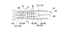
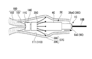
- the vaginal wall incision instrument 1 is a portion 101 (refer to FIG. 4, hereinafter referred to as a “first portion 101”) that faces the cervix 102 from the abutting portion 11 side. ) Until the abutment portion 11 comes into contact.
- the concave surface portion 13 of the cup-shaped member 12 contacts the cervix 102 so as to cover the first portion 101.
- the guide hole 14 formed in the cup-shaped member 12 allows the conductive member 17 to protrude in a direction substantially along the outer surface of the cervix 102 in a direction inclined with respect to the center line of the inner cylinder member 9. Further, the conductive member 17 is supported via the insulating member 18. At this time, the protruding direction of the distal portion of the conductive member 17 is a straight direction that intersects the boundary portion between the cervix 102 and the vaginal canal 110. The distal end of the positioning member 15 is inserted into the uterine ostium 103.
- the operator confirms that no other tissue is in contact with the vicinity of the boundary between the cervix 102 and the vaginal canal 110 under a laparoscopic view. Thereafter, the slider 26 (see FIG. 3) is moved toward the distal side of the shaft body 22. As a result, as shown in FIG. 5, the conductive member 17 protrudes toward the boundary between the cervix 102 and the vaginal canal 110. The operator may move the slider 26 toward the distal side of the shaft body 22 while applying a high-frequency current to the conductive member 17 using the high-frequency power supply device 30 as necessary.
- the distal end of the conductive member 17 penetrates the vagina wall 111 so as to penetrate the vagina wall 111 and reach the abdominal cavity at the boundary between the cervix 102 and the vaginal canal 110.
- the position of the distal end of the conductive member 17 can be grasped by a laparoscope.
- the operator stops the operation of the slider 26 when the conductive member 17 penetrates the vagina wall 111. Since the convex portion 28 of the slider 26 and the projection 25 of the serrated portion 24 of the shaft body 22 are engaged, the slider 26 is held at a position where the operator stops operating the slider 26. Thereby, even if the operator lifts his / her finger from the slider 26, the conductive member 17 is held in a state of penetrating the vagina wall 111.
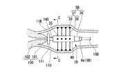
- the operator rotates the shaft body 22 of the operation unit 20 around the center line of the shaft body 22 while energizing the conductive member 17 with a high-frequency current.
- the rotation direction of the shaft body 22 may be any.
- the shaft body 22 rotates the cup-shaped member 12 via the connecting member 10 and the inner cylinder member 9.
- the cup-shaped member 12 is rotated about the uterine ostium 103 as the distal end of the positioning member 15 is inserted into the uterine ostium 103.
- the outer cylinder member 4 does not rotate by the rotation operation of the shaft body 22. For this reason, in a state where the locking portion 5 provided on the outer cylinder member 4 is locked to the inner surface of the vagina wall 111, the conductive member 17 cuts the vagina wall 111 while rotating in the circumferential direction of the vagina wall 111.
- the conductive member 17 rotates once in the circumferential direction of the vagina wall 111, the conductive member 17 returns to the penetration site to the vagina wall 111. That is, as shown in FIG. 6, the vaginal wall 111 is separated over the entire circumference with the boundary portion between the cervix 102 and the vaginal canal 110 as a separation line. As a result, the uterus 100 is separated from the vaginal canal 110.
- the uterus 100 When the uterus 100 is separated from the vagina tube 110, the uterus 100 is taken out of the body through the vagina tube 110 or an incision site formed in the abdominal wall by a known technique.
- the conductive member 17 penetrating the vaginal canal 110 is moved to the outer cylinder member 4 by rotating the shaft body 22 of the operation unit 20 around the center line of the shaft body 22 as a rotation center. And the center line of the inner cylinder member 9 can be rotated about the rotation center.
- the outer surface of the outer tube member 4 is in contact with the inner surface of the vaginal tube 110, and the vaginal tube 110 has a cylindrical shape centering on the center line of the outer tube member 4. For this reason, when the conductive member 17 rotates around the center line of the outer cylinder member 4 and the inner cylinder member 9, the conductive member 17 becomes the center line of the vaginal tube 110 in the vaginal tube 110 that is cylindrical.
- the vaginal canal 110 can be cut along a circular cutting line extending in the circumferential direction of the vaginal canal 110 in a plane perpendicular to the plane.
- the vaginal canal 110 can be separated along an ideal separation line at the boundary portion between the cervix 102 and the vaginal canal 110.
- the operation for separating the vaginal canal 110 is only an operation of rotating the shaft body 22 around the center line of the shaft body 22 while the high-frequency current is applied to the conductive member 17, There is no need for coordinated operation of multiple instruments. That is, since the vaginal canal 110 is held by the outer cylinder member 4 and the positioning for aligning the conductive member 17 with the separation line has already been performed, the operator can only perform the rotation operation of the shaft body 22. , The vaginal wall 111 can be separated along an ideal separation line.
- the separation starts from the portion where the conductive member 17 penetrates the vagina wall 111, and when the separation is completed, the conductive member 17 returns to the penetration portion.
- the conductive member 17 rotates. Therefore, it is easy to adjust the position of the conductive member 17 during the separation work, and the workability is excellent.
- the distal end portion of the conductive member 17 advances and retreats in a direction intersecting the center line of the vaginal tube 110, and the conductive member 17 goes to the distal side. Accordingly, the vagina wall 111 is penetrated so as to go outward in the radial direction of the vaginal canal 110. Therefore, the cutting operation by the vaginal wall incision tool 1 according to the present embodiment is such that the amount of excision of the vaginal canal 110 is smaller than when the conductive member 17 protrudes in a direction orthogonal to the center line of the vaginal canal 110. The vaginal canal 110 can be preserved less.
- the conductive member 17 touches the cervix 102 when the operator penetrates the conductive member 17 into the vaginal canal 110 or when the operator uses the conductive member 17 to separate the vaginal tube 110 over the entire circumference. Hateful. Further, compared to the case where the conductive member 17 protrudes in a direction orthogonal to the center line of the vaginal canal 110, the possibility that the distal end of the conductive member 17 may accidentally touch other living tissue in the abdominal cavity is reduced. Can be suppressed.
- the cup-shaped member 12 when the concave surface portion 13 of the cup-shaped member 12 is in contact with the first portion 101, the cup-shaped member 12 is stable while covering the first portion 101. Therefore, the operator simply moves the slider 26 to the distal side while pressing the concave portion 13 of the cup-shaped member 12 against the first portion 101, so that the conductive member 17 is moved to the boundary portion between the cervix 102 and the vaginal canal 110. It can penetrate easily.
- the cup-shaped member 12 In a state where the concave surface portion 13 of the cup-shaped member 12 is in contact with the first portion 101, the cup-shaped member 12 can rotate around the first portion 101 as a rotation center. Therefore, the operator simply rotates the shaft 22 in a state where the concave surface portion 13 of the cup-shaped member 12 is pressed against the first portion 101, and along the separation line at the boundary portion between the cervix 102 and the vaginal canal 110.
- the conductive member 17 can be easily rotated.
- the distal end of the conductive member 17 can easily reach the boundary portion between the cervix 102 and the vaginal canal 110.
- the cup-shaped member 12 can be rotated about the uterine ostium 103 by the positioning member 15.
- the positioning member 15 suppresses the displacement of the uterus 100 with respect to the vaginal canal 110 and the displacement of the vaginal wall incision tool 1 with respect to the uterus 100. Therefore, it is possible to suppress displacement of the conductive member 17 from the separation line in the process of separating the vaginal wall 111 using the conductive member 17.
- the locking portion 5 provided on the outer peripheral surface of the outer cylinder member 4 holds the vagina wall 111 so that the positions of the outer cylinder member 4 and the vagina wall 111 do not shift. Therefore, the vaginal canal 110 is hardly twisted during the separation operation, and the vaginal wall 111 can be easily separated along the ideal separation line.
- An airtight valve 7 that brings the outer cylinder member 4 and the interior portion 8 into an airtight state is provided in the exterior portion 3. Therefore, when performing a pneumothorax in order to easily perform a laparoscopic procedure, gas leakage from the gap between the outer cylinder member 4 and the interior portion 8 is minimized, and the outer cylinder member 4 The interior portion 8 can rotate around the center line of the outer cylinder member 4 as a rotation center.
- the locking portion 5 provided in the outer cylinder member 4 can also suppress leakage of gas filled in the abdominal cavity by inhalation.
- FIG. 7 is a side view showing a configuration of a modified example of the vaginal wall incising instrument according to the embodiment.
- the locking portion 5 described in the above embodiment has the balloon 31 and the air supply conduit 32 as shown in FIG. 7 instead of the annular member 6. And the configuration is different.
- the balloon 31 has an annular shape around the center line of the outer cylinder member 4 on the outer peripheral surface of the outer cylinder member 4, and is fixed to the outer peripheral surface of the outer cylinder member 4.
- the balloon 31 is a film that can be expanded and contracted so as to expand when filled with liquid or gas. When the inside of the balloon 31 is filled with liquid or gas, the balloon 31 expands in a donut shape.
- the air supply line 32 is a cylindrical member having a distal end communicating with the inside of the balloon 31 and a proximal end connected to a pump.
- the air supply duct 32 is fixed to the outer surface of the outer cylinder member 4, for example. Further, the air supply conduit 32 passes through the outer cylinder member 4 and is drawn into the outer cylinder member 4, and extends toward the proximal side of the main body 2 through the gap between the outer cylinder member 4 and the interior portion 8. Also good.
- the pressing force of the balloon 31 against the vaginal wall 110 can be adjusted by adjusting the diameter of the balloon 31 that is inflated.
- the outer cylinder member 4 can be locked to the vagina wall 111 with an appropriate locking force corresponding to individual differences among patients.
- FIG. 8 is a perspective view showing a part of the vaginal wall incising instrument 1A according to the present embodiment.
- FIG. 9 is a cross-sectional view of the distal portion of the vaginal wall incising tool 1A according to the present embodiment.
- the vaginal wall incision tool 1A includes a main body 2A having a configuration different from that of the main body 2 described in the first embodiment.
- the main body 2A has an exterior part 3A and an interior part 8A.
- the exterior portion 3A differs from the exterior portion 3 of the first embodiment in that the exterior portion 3A has a first stopper 33 on the inner peripheral surface of the outer cylinder member 4.
- the interior portion 8A has the second stopper 34 on the outer peripheral surface of the inner cylindrical member 9, and the interior portion of the first embodiment in that the inner cylindrical member 9 has a guide hole 14 instead of the cup-shaped member 12. 8 and the configuration is different.
- it has the incision part 16 and the operation part 20 similar to 1st Embodiment.
- the first stopper 33 provided on the outer cylinder member 4 extends in the circumferential direction of the outer cylinder member 4 on the inner peripheral surface of the outer cylinder member 4 and is provided over the entire circumference of the outer cylinder member 4.
- the first stopper 33 protrudes from the inner peripheral surface of the outer cylinder member 4 toward the radially inner side of the outer cylinder member 4.
- the second stopper 34 provided on the inner cylinder member 9 is provided on the outer peripheral surface of the inner cylinder member 9 so as to extend in the circumferential direction of the inner cylinder member 9 and over the entire circumference of the inner cylinder member 9.
- the second stopper 34 projects from the outer peripheral surface of the inner cylinder member 9 toward the radially outer side of the inner cylinder member 9.
- the clearance is such that the second stopper 34 is rotatable with respect to the outer cylinder member 4 about the center line of the outer cylinder member 4 as the rotation center.
- the second stopper 34 is located distal to the first stopper 33. The proximal outer surface of the second stopper 34 can come into contact with the distal outer surface of the first stopper 33.
- the guide hole 14 formed in the inner cylinder member 9 guides the conductive member 17 in a direction inclined with respect to the center line of the inner cylinder member 9 as in the first embodiment. Further, in a state where the second stopper 34 is in contact with the first stopper 33, a gap is formed between the distal end of the outer cylinder member 4 and the interior portion 8A so that the conductive member 17 can protrude. Yes. For this reason, in this embodiment, the electrically-conductive member 17 protrudes from the clearance gap between the distal end of the outer cylinder member 4, and the interior part 8A.
- the vaginal wall incising tool 1A can also cut the vaginal canal 110 along an ideal separation line set at the boundary between the cervix 102 and the vaginal canal 110. .
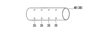
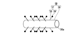
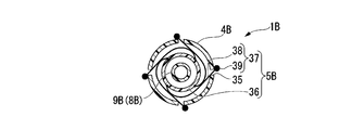
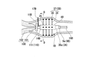
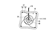
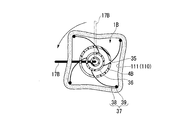
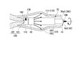
- FIG. 10 is a perspective view showing the main body of the vaginal wall incising tool 1B according to the present embodiment.
- FIG. 11 is a perspective view showing the outer cylinder member 4B of the vaginal wall incision 1B according to the present embodiment.
- FIG. 12 is a perspective view showing the intermediate cylinder member 36 of the vaginal wall incising tool 1B according to the present embodiment.
- FIG. 13 is a perspective view showing the inner cylinder member 9B of the vaginal wall incising tool 1B according to the present embodiment.
- FIG. 14 is a perspective view showing an incision 16B of the vaginal wall incising instrument 1B according to the present embodiment.
- FIG. 15 is a cross-sectional view of the inner cylinder member 9B of the vaginal wall incising tool 1B according to the present embodiment.
- FIG. 16 is a view for explaining the operation of the vaginal wall incising tool 1B according to this embodiment, and is a cross-sectional view taken along the line AA in FIG.
- FIG. 17 is a view for explaining the operation of the vaginal wall incising tool 1B according to this embodiment, and is a cross-sectional view taken along the line AA in FIG.
- the vaginal wall incision tool 1B according to the present embodiment includes a main body 2B having a configuration different from that of the main body 2 described in the first embodiment.
- the vaginal wall incision tool 1B according to the present embodiment includes the incision portion 16B described in the first embodiment instead of the incision portion 16 described in the first embodiment.
- the main body portion 2B includes an exterior portion 3B, a locking portion 5B, and an interior portion 8B.
- the exterior portion 3B includes an outer cylinder member 4B having a shape different from that of the outer cylinder member 4 described in the first embodiment.
- the locking portion 5B is arranged inside the exterior portion 3B and has a different configuration from the locking portion 5 described in the first embodiment.
- the interior portion 8B includes an inner cylinder member 9B that is disposed inside the locking portion 5B and has a configuration different from that of the interior portion 8 described in the first embodiment.
- the outer cylinder member 4B of the exterior part 3B is a cylindrical member in which a plurality of through holes 35 are formed on the outer peripheral surface.
- the plurality of through holes 35 formed on the outer peripheral surface of the outer cylinder member 4B are arranged side by side or randomly at positions separated from each other in the circumferential direction of the outer cylinder member 4B.
- the plurality of through holes 35 formed in the outer peripheral surface of the outer cylinder member 4B are arranged at positions separated from each other in the center line direction of the outer cylinder member 4B.
- the locking portion 5 ⁇ / b> B includes an intermediate cylinder member 36 and a plurality of anchors 37.
- the intermediate cylinder member 36 is a cylindrical member disposed between the outer cylinder member 4B and the inner cylinder member 9B.
- the plurality of anchors 37 are fixed to the outer surface of the intermediate cylinder member 36.
- the distal end of the intermediate cylinder member 36 is located on the proximal side of the position of the distal end of the outer cylinder member 4B or the distal end of the outer cylinder member 4B.
- the proximal end of the intermediate cylinder member 36 is located closer to the proximal side than the proximal end of the outer cylinder member 4B.
- the proximal portion of the intermediate cylinder member 36 is a first grip portion 36a for the operator to rotate the intermediate cylinder member 36 with his hand.
- An inner cylinder member 9 ⁇ / b> B is inserted into the intermediate cylinder member 36.
- the center line of the intermediate cylinder member 36 is positioned substantially coaxially with respect to both the center line of the outer cylinder member 4B and the center line of the inner cylinder member 9B.
- the intermediate cylinder member 36 is rotatable with respect to the outer cylinder member 4B and the inner cylinder member 9B.
- the anchor 37 has a wire 38 and an end member 39.
- the wire 38 is fixed to the outer peripheral surface of the intermediate cylinder member 36.
- the end member 39 is fixed to the end of the wire 38.
- the wire 38 of the anchor 37 has a restoring force that can be restored to a substantially straight line when no external force is applied.
- One end of the wire 38 of the anchor 37 is fixed to the intermediate cylinder member 36 by bonding or the like so as to be inserted into the side wall of the intermediate cylinder member 36, for example.
- each wire 38 of the anchor 37 is fixed perpendicularly to the outer peripheral surface of the intermediate cylinder member 36.
- the end member 39 of the anchor 37 has a curved surface that does not irritate the mucous membrane.
- the end member 39 of the anchor 37 is a spherical member to which the end of the wire 38 of the anchor 37 is inserted and fixed.
- the outer diameter of the end member 39 is larger than the inner diameter of the through hole 35 formed in the outer peripheral surface of the outer cylinder member 4B.
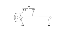
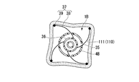
- the interior portion 8B includes an inner cylinder member 9B and a contact portion 11B.
- the inner cylinder member 9B has a substantially cylindrical shape, and is opened laterally at the distal portion and opened at the proximal end.
- the contact portion 11B is provided at the distal end of the inner cylinder member 9B.
- the proximal portion of the inner cylinder member 9B in the interior portion 8B is a second grip 9a that can be gripped by the operator to rotate the inner cylinder member 9B around the center line of the inner cylinder member 9B.
- the opening at the side of the distal portion of the inner cylinder member 9B is an opening for projecting a conductive member 17B described later. That is, in this embodiment, the conductive member 17B is inserted distally from the proximal end of the inner cylinder member 9B, and the conductive member 17B protrudes from the side opening of the distal portion of the inner cylinder member 9B. As shown in FIG. 15, the opening at the side of the distal portion of the inner cylinder member 9B has a curved surface or a plane that is inclined with respect to the center line of the inner cylinder member 9B inside the inner cylinder member 9B. .
- the side opening of the distal portion of the inner cylinder member 9B is similar to the guide hole 14 described in the first embodiment, and the conductive member 17B faces the boundary portion between the cervix and the vaginal canal.
- the contact portion 11B has a disk shape along a plane orthogonal to the center line of the inner cylinder member 9.
- the contact portion 11B of the present embodiment may have a cup shape having a concave surface portion that can contact the cervix as in the first embodiment.
- the uterine vagina part can contact
- the conductive member 17B can be positioned so that the conductive member 17B is directed to the boundary portion between the cervix and the vaginal canal.
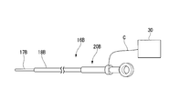
- the incision 16B for example, a known high-frequency incision tool having a needle-like electrode can be appropriately selected and employed.
- the incision 16B includes an insulating member 18B (for example, an insulating sheath), a conductive member 17B (for example, a needle electrode), and an operating means 20B.
- the insulating member 18B corresponds to the insulating member 18 described in the first embodiment.
- the conductive member 17B (for example, a needle electrode) corresponds to the conductive member 17 described in the first embodiment, and is inserted through the insulating member 18B.
- the operating means 20B is fixed to the proximal end of the insulating member 18B.
- the operating means 20B is provided for advancing and retracting the conductive member 17B.
- FIG. 18 is a view for explaining a procedure using the vaginal wall incising tool 1B according to the present embodiment.
- FIG. 19 is a view for explaining a procedure using the vaginal wall incising tool 1B according to this embodiment, and is a cross-sectional view taken along the line BB of FIG.
- FIG. 20 is a diagram for explaining a procedure using the vaginal wall incising tool 1B according to the present embodiment.
- FIG. 21 is a view for explaining a procedure using the vaginal wall incising tool 1B according to the present embodiment, and is a cross-sectional view taken along the line CC of FIG. FIG.
- FIG. 22 is a view for explaining a procedure using the vaginal wall incising tool 1B according to the present embodiment.
- FIG. 23 is a view for explaining a procedure using the vaginal wall incising tool 1B according to this embodiment, and is a cross-sectional view taken along the line DD of FIG.
- FIG. 24 is a diagram for explaining a procedure using the vaginal wall incising tool 1B according to the present embodiment.
- FIG. 25 is a view for explaining a procedure using the vaginal wall incising tool 1B according to this embodiment, and is a cross-sectional view taken along the line EE of FIG.
- the operator rotates the intermediate cylinder member 36 with respect to the outer cylinder member 4B about the center line of the intermediate cylinder member 36 as a rotation center, thereby passing the wire 38 of the anchor 37 through the outer cylinder member 4B. It can be taken in and out through the hole 35.
- the wire 38 of the anchor 37 is pushed out of the outer cylinder member 4B through the respective through holes 35 on the outer peripheral surface of the outer cylinder member 4B while being restored to the linear state (see FIG. 17).
- a restoring force for returning to a straight state acts on the wire 38 of the anchor 37. Therefore, depending on the magnitude of the restoring force of the wire 38, the wire 38 is pushed out of the outer cylinder member 4B through the through holes 35 of the outer cylinder member 4B only by loosening the force for winding the wire 38 around the intermediate cylinder member 36. In some cases.
- the wire 38 of the anchor 37 presses the vagina wall 111 outward in the radial direction via the end member 39 as shown in FIGS.
- the outer cylindrical member 4B is attached to the vagina wall 111 by the frictional force between each end member 39 fixed to the wire 38 of the anchor 37 and the vagina wall 111. It is locked against.
- Each wire 38 has a restoring force such that the wire 38 is pushed out of the outer cylinder member 4B through each through hole 35 of the outer cylinder member 4B simply by loosening the force of winding the wire 38 around the intermediate cylinder member 36. In this case, the rotation of the intermediate cylindrical member 36 stops at a position where the magnitude of the restoring force of each wire 38 and the reaction force from the vagina wall 111 are equal.
- the operator can guide the guide hole 14B, which is a side opening of the distal portion of the inner cylinder member 9.
- the conductive member 17B is protruded from As a result, like the first embodiment, the distal end of the conductive member 17B penetrates the vaginal wall 111, and the conductive member 17B penetrates the vaginal wall 111 at the boundary between the cervix 102 and the vaginal canal 110. It is.
- the operator rotates the second gripping portion 9a around the center line of the inner cylindrical member 9B as the rotation center as shown in FIGS. 24 and 25 in a state where the high-frequency current is applied to the conductive member 17B.
- the conductive member 17B is rotated around the center line of the vaginal canal 110 with respect to the vagina wall 111 locked to the outer cylinder member 4B by the locking portion 5B.
- the electroconductive member 17B separates the vagina wall 111 over a perimeter.
- the vaginal wall 111 can be easily separated along an ideal separation line at the boundary between the cervix 102 and the vaginal canal 110.
- the operation of appropriately adjusting the length of the wire 38 of the anchor 37 can be easily performed by adjusting the amount of rotation of the intermediate cylinder member 36 relative to the outer cylinder member 4B.
- Each wire 38 has a restoring force such that the wire 38 is pushed out of the outer cylinder member 4B through each through hole 35 of the outer cylinder member 4B simply by loosening the force of winding the wire 38 around the intermediate cylinder member 36.
- the rotation of the intermediate cylindrical member 36 stops at a position where the magnitude of the restoring force of each wire 38 and the reaction force from the vagina wall 111 are equal. Therefore, the outer cylinder member 4B can be locked to the vagina wall 111 with a fixed locking force regardless of individual differences among patients.
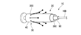
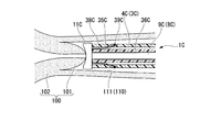
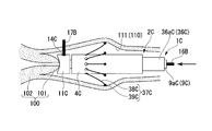
- FIG. 26 is an overall view showing the vaginal wall incising tool 1C according to the present embodiment.
- FIG. 27 is a perspective view showing the outer cylinder member 4C of the vaginal wall incising tool 1C according to the present embodiment.
- FIG. 28 is a perspective view showing an intermediate cylinder member 36C of the vaginal wall incising tool 1C according to the present embodiment.
- FIG. 29 is a perspective view showing the inner cylinder member 9C of the vaginal wall incising tool 1C according to the present embodiment.
- FIG. 30 is a cross-sectional view of the inner cylinder member 9C of the vaginal wall incising tool 1C according to the present embodiment.
- the vaginal wall incision tool 1C according to the present embodiment includes a main body 2C having a configuration different from that of the main body 2 described in the first embodiment.
- the vaginal wall incising tool 1C according to the present embodiment includes the incision 16B described in the third embodiment, instead of the incision 16 described in the first embodiment.
- the main body portion 2C includes an exterior portion 3C, a locking portion 5C, and an interior portion 8C.
- 3 C of exterior parts have the outer cylinder member 4C from which a shape differs from the outer cylinder member 4 demonstrated in 1st Embodiment.
- the locking part 5C is arranged inside the exterior part 3C and has a different configuration from the locking part 5 described in the first embodiment.
- the interior portion 8C includes an inner cylinder member 9C that is disposed inside the locking portion 5C and has a configuration different from that of the interior portion 8 described in the first embodiment.
- the outer cylindrical member 4C of the exterior portion 3C is a cylindrical member having a plurality of through holes 35C formed on the outer peripheral surface.
- the plurality of through holes 35C of the outer cylinder member 4C are arranged side by side or randomly at positions separated from each other in the circumferential direction of the outer cylinder member 4C.
- the locking portion 5C includes an intermediate cylinder member 36C and a plurality of anchors 37C.
- the intermediate cylinder member 36C is a cylindrical member disposed between the outer cylinder member 4C and the inner cylinder member 9C.
- the plurality of anchors 37C are fixed to the outer surface of the intermediate cylinder member 36C.
- the distal end of the intermediate cylinder member 36C is located on the proximal side of the position of the distal end of the outer cylinder member 4C or the distal end of the outer cylinder member 4C.
- the proximal end of the intermediate cylinder member 36C is located closer to the proximal side than the proximal end of the outer cylinder member 4C.
- the proximal portion of the intermediate cylinder member 36C is a first grip portion 36aC that the operator holds in his hand to move the intermediate cylinder member 36C forward and backward with respect to the outer cylinder member 4C.
- An inner cylinder member 9C is inserted into the intermediate cylinder member 36C.
- the center line of the intermediate cylinder member 36C is positioned substantially coaxially with respect to both the center line of the outer cylinder member 4C and the center line of the inner cylinder member 9C.
- the intermediate cylinder member 36C can advance and retreat in the direction of the center line of the outer cylinder member 4C with respect to the outer cylinder member 4C, and the intermediate cylinder member 36C has a center line of the inner cylinder member 9C with respect to the inner cylinder member 9C. Can be rotated around the center of rotation.
- the anchor 37C has a wire 38C and an end member 39C.
- the wire 38C is fixed to the outer peripheral surface of the intermediate cylinder member 36C.
- the end member 39C is fixed to the end of the wire 38C.
- the wire 38 ⁇ / b> C of the anchor 37 ⁇ / b> C has a restoring force that can be restored to a substantially linear shape when no external force is applied.
- One end of the wire 38C of the anchor 37C is fixed to the intermediate cylinder member 36C by adhesion or the like so as to be inserted into the side wall of the intermediate cylinder member 36C or along the outer peripheral surface of the intermediate cylinder member 36C.
- the wire 38C of the anchor 37C is inclined on the outer peripheral surface of the distal end of the intermediate cylindrical member 36C so as to gradually move away from the outer peripheral surface of the intermediate cylindrical member 36C as going from the distal end of the intermediate cylindrical member 36C to the proximal side. Is fixed.
- the end member 39C of the anchor 37C has a curved surface that does not irritate the mucous membrane.
- the end member 39C of the anchor 37C is a spherical member similar to the third embodiment.
- the outer diameter of the end member 39C is larger than the inner diameter of the through hole 35C formed on the outer peripheral surface of the outer cylinder member 4C.
- the interior portion 8C includes a cylindrical inner tube member 9C and a contact portion 11C.
- 11 C of contact parts are provided in the distal end of the inner cylinder member 9C, and are connected with the inside of the inner cylinder member 9C.
- the proximal portion of the inner cylinder member 9C in the interior portion 8C is a second gripping part 9aC that can be gripped by the operator to rotate the inner cylinder member 9C around the center line of the inner cylinder member 9B.
- a guide hole 14C is formed in the contact portion 11C.
- the guide hole 14C is formed to project the conductive member 17B inserted from the proximal side to the distal side of the inner cylinder member 9C toward the radially outer side of the inner cylinder member 9C.
- the guide hole 14C supports the conductive member 17B so that the distal end of the conductive member 17B can penetrate the boundary portion between the cervix and the vaginal canal.
- the insulating member 18B of the incision portion 16B is not fixed to the inner surface of the guide hole 14C.
- the contact portion 11C has a disk shape along a plane orthogonal to the center line of the inner cylindrical member 9 as in the third embodiment.
- the first portion 101 can abut on the distal outer surface of the abutting portion 11B, and the conductive member 17B has a boundary portion between the cervix and the vaginal canal as in the concave portion 13 described in the first embodiment.
- the conductive member 17B can be positioned so as to go to.
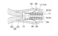
- FIG. 31 is a view for explaining the operation of the vaginal wall incising tool 1C according to the present embodiment.
- FIG. 32 is a diagram for explaining the operation of the vaginal wall incising tool 1C according to the present embodiment.
- FIG. 33 to FIG. 36 are diagrams for explaining a procedure using the vaginal wall incising tool 1C according to the present embodiment. As shown in FIGS.
- the operator moves the intermediate cylinder member 36C forward and backward along the center line of the intermediate cylinder member 36C with respect to the outer cylinder member 4C, thereby
- the wire 38C can be taken in and out through the through hole 35C of the outer cylinder member 4C.
- the intermediate cylinder member 36C is arranged so that the wire 38C of the anchor 37C is accommodated in the gap between the intermediate cylinder member 36C and the outer cylinder member 4C. Is pushed toward the distal side of the outer cylinder member 4C. Thereafter, in the state where the insertion of the main body 2C into the vaginal canal 110 is completed and the contact portion 11C is in contact with the first portion 101, as shown in FIG. The intermediate cylinder member 36C is moved to the right.
- the wire 38C of the anchor 37C is pushed out of the outer cylinder member 4C through the through hole 35C on the outer peripheral surface of the outer cylinder member 4C.
- the wire 38C of the anchor 37C is bent toward the radially outer side of the outer cylinder member 4C by the inner surface of the through hole 35C of the outer cylinder member 4C.
- the wire 38C of the anchor 37C is inclined so as to gradually move away from the outer peripheral surface of the outer cylinder member 4C as it goes to the proximal side of the outer cylinder member 4C. Presses the vaginal wall 111.
- the wire 38C of the anchor 37C presses the vagina wall 111 outward in the radial direction of the vagina wall 111 via the end member 39C.
- the outer cylinder member 4C is attached to the vagina wall 111 by the frictional force between each end member 39C fixed to the wire 38C of the anchor 37C and the vagina wall 111. It is locked against.
- the operator causes the conductive member 17B to protrude from the guide hole 14C.
- the distal end of the conductive member 17B penetrates the vaginal wall 111, and the conductive member 17B penetrates the vaginal wall 111 at the boundary between the cervix 102 and the vaginal canal 110. (See FIG. 35).
- the operator rotates the second grip 9aC around the center line of the inner cylinder member 9C as the center of rotation as shown in FIG. 36 in a state where a high-frequency current is applied to the conductive member 17B.
- the conductive member 17B is rotated around the center line of the vaginal canal 110 with respect to the vagina wall 111 locked by the locking portion 5C with respect to the outer cylinder member 4C.
- the electroconductive member 17B separates the vagina wall 111 over a perimeter.
- the vaginal wall incising tool 1C can easily separate the vaginal wall 111 along an ideal separation line at the boundary between the cervix 102 and the vaginal canal 110. Can do.
- the operation of appropriately adjusting the length of the wire 38 of the anchor 37 can be easily performed by adjusting the amount of rotation of the intermediate cylinder member 36 relative to the outer cylinder member 4C.
- FIG. 1 Another aspect of the present invention is a method for cutting a vaginal wall, wherein an incision (knife) is passed from the inside of the vaginal canal into the abdominal cavity at the boundary between the vaginal canal and the cervix, and the knife In this state, the knife is rotated around the center line of the vaginal canal while the vaginal canal is penetrated, and the vaginal canal is separated over the entire circumference.
- the uterus and the vaginal canal can be separated using the boundary portion between the cervix and the vaginal canal as a separation line.
- the knife may penetrate the vaginal canal at a direction intersecting the center line of the vaginal canal and at an angle away from the cervix and the uterine body.
- a contact portion that can contact the uterine vagina may be inserted into the vaginal canal, and the knife may be supported by the contact portion.
- a positioning member that can be inserted into the uterine ostium may be inserted into the uterine ostium, and the movement direction of the knife may be restricted by the positioning member to a rotation direction with the uterine ostium as the rotation center.
- Each of the above embodiments can provide a vaginal wall incision tool capable of accurately cutting a living tissue along the cutting line in a short time.
Abstract
Priority Applications (4)
| Application Number | Priority Date | Filing Date | Title |
|---|---|---|---|
| JP2015531188A JP5815165B1 (ja) | 2014-01-10 | 2014-11-17 | 膣壁切開具 |
| CN201480033967.8A CN105324089B (zh) | 2014-01-10 | 2014-11-17 | 阴道壁切开器具 |
| EP14877720.4A EP3092967A4 (fr) | 2014-01-10 | 2014-11-17 | Outil de coupe de paroi vaginale |
| US14/971,449 US9662167B2 (en) | 2014-01-10 | 2015-12-16 | Vaginal wall incision instrument |
Applications Claiming Priority (2)
| Application Number | Priority Date | Filing Date | Title |
|---|---|---|---|
| JP2014-003132 | 2014-01-10 | ||
| JP2014003132 | 2014-01-10 |
Related Child Applications (1)
| Application Number | Title | Priority Date | Filing Date |
|---|---|---|---|
| US14/971,449 Continuation US9662167B2 (en) | 2014-01-10 | 2015-12-16 | Vaginal wall incision instrument |
Publications (1)
| Publication Number | Publication Date |
|---|---|
| WO2015104901A1 true WO2015104901A1 (fr) | 2015-07-16 |
Family
ID=53523742
Family Applications (1)
| Application Number | Title | Priority Date | Filing Date |
|---|---|---|---|
| PCT/JP2014/080353 WO2015104901A1 (fr) | 2014-01-10 | 2014-11-17 | Outil de coupe de paroi vaginale |
Country Status (5)
| Country | Link |
|---|---|
| US (1) | US9662167B2 (fr) |
| EP (1) | EP3092967A4 (fr) |
| JP (1) | JP5815165B1 (fr) |
| CN (1) | CN105324089B (fr) |
| WO (1) | WO2015104901A1 (fr) |
Cited By (1)
| Publication number | Priority date | Publication date | Assignee | Title |
|---|---|---|---|---|
| CN113229908A (zh) * | 2021-05-12 | 2021-08-10 | 郑州大学第三附属医院(河南省妇幼保健院) | 一种产科用破膜器 |
Families Citing this family (12)
| Publication number | Priority date | Publication date | Assignee | Title |
|---|---|---|---|---|
| JP1576779S (fr) * | 2016-10-05 | 2017-05-22 | ||
| JP1576777S (fr) * | 2016-10-05 | 2017-05-22 | ||
| JP1577397S (fr) * | 2016-10-05 | 2017-05-29 | ||
| US11253308B2 (en) | 2017-05-12 | 2022-02-22 | Covidien Lp | Colpotomy systems, devices, and methods with rotational cutting |
| US11090082B2 (en) * | 2017-05-12 | 2021-08-17 | Covidien Lp | Colpotomy systems, devices, and methods with rotational cutting |
| US11213320B2 (en) | 2017-05-12 | 2022-01-04 | Covidien Lp | Uterine manipulator with detachable cup and locking occluder |
| US10980571B2 (en) | 2017-08-15 | 2021-04-20 | Covidien Lp | Occlusion devices, systems, and methods |
| US11344292B2 (en) | 2018-06-14 | 2022-05-31 | Covidien Lp | Trans-vaginal cuff anchor and method of deploying same |
| DE112020005581T5 (de) | 2019-11-11 | 2022-09-01 | Gyrus Acmi, Inc. D/B/A Olympus Surgical Technologies America | Kolpotomie-schalen-anordnung |
| US11969203B2 (en) | 2020-02-14 | 2024-04-30 | Covidien Lp | Colpotomy system with applied energy |
| CN111956310B (zh) * | 2020-08-26 | 2022-06-24 | 王中显 | 一种经阴道的宫颈癌子宫切除装置 |
| CN112535523A (zh) * | 2021-01-22 | 2021-03-23 | 上海长征医院 | 一种适合宫颈癌的新型举宫杯 |
Citations (10)
| Publication number | Priority date | Publication date | Assignee | Title |
|---|---|---|---|---|
| JPH08500990A (ja) * | 1992-06-24 | 1996-02-06 | カー・イュー・レオフェン・リサーチ・アンド・ディベロプメント | 腹腔鏡による子宮摘出のための器具セット |
| JPH10507384A (ja) * | 1994-10-18 | 1998-07-21 | ブレアデン プリシッジョン インスツルメンツ,インコーポレイテッド | 膣切開術用の膣エキステンダ |
| JPH10234743A (ja) | 1997-02-27 | 1998-09-08 | Olympus Optical Co Ltd | 高周波切除具 |
| JPH11336A (ja) * | 1997-06-11 | 1999-01-06 | Olympus Optical Co Ltd | 体内挿入具 |
| US20030216731A1 (en) * | 2002-05-16 | 2003-11-20 | Dennis Martin E. | Device and method for facilitating a laparascopic supracervical hysterectomy |
| US20050070895A1 (en) * | 2003-09-30 | 2005-03-31 | Thomas Ryan | Electrosurgical instrument and method for transecting an organ |
| US20090182329A1 (en) * | 2008-01-16 | 2009-07-16 | Tyco Healthcare Group Lp | Uterine Sealer |
| JP2010505457A (ja) * | 2006-07-06 | 2010-02-25 | レロイ・エル・イエーツ | 切除装置 |
| JP2010178766A (ja) | 2009-02-03 | 2010-08-19 | Hoya Corp | 処置用内視鏡 |
| US20120143209A1 (en) * | 2010-12-06 | 2012-06-07 | Soulor Surgical Inc | Apparatus for treating a portion of a reproductive system and related methods of use |
Family Cites Families (7)
| Publication number | Priority date | Publication date | Assignee | Title |
|---|---|---|---|---|
| US6032673A (en) * | 1994-10-13 | 2000-03-07 | Femrx, Inc. | Methods and devices for tissue removal |
| US6077257A (en) * | 1996-05-06 | 2000-06-20 | Vidacare, Inc. | Ablation of rectal and other internal body structures |
| JP3342021B2 (ja) * | 1997-10-17 | 2002-11-05 | サーコン コーポレーション | 組織を貫通する医療機器システム |
| US5951550A (en) * | 1998-03-11 | 1999-09-14 | Utah Medical Products, Inc. | Endocervical conization electrode apparatus |
| US8025670B2 (en) * | 2006-11-22 | 2011-09-27 | Minos Medical | Methods and apparatus for natural orifice vaginal hysterectomy |
| US20090318914A1 (en) * | 2008-06-18 | 2009-12-24 | Utley David S | System and method for ablational treatment of uterine cervical neoplasia |
| WO2013115892A1 (fr) * | 2012-01-30 | 2013-08-08 | Brigham And Women's Hospital, Inc. | Manipulateur utérin fonctionnel |
-
2014
- 2014-11-17 JP JP2015531188A patent/JP5815165B1/ja active Active
- 2014-11-17 CN CN201480033967.8A patent/CN105324089B/zh active Active
- 2014-11-17 WO PCT/JP2014/080353 patent/WO2015104901A1/fr active Application Filing
- 2014-11-17 EP EP14877720.4A patent/EP3092967A4/fr not_active Withdrawn
-
2015
- 2015-12-16 US US14/971,449 patent/US9662167B2/en active Active
Patent Citations (10)
| Publication number | Priority date | Publication date | Assignee | Title |
|---|---|---|---|---|
| JPH08500990A (ja) * | 1992-06-24 | 1996-02-06 | カー・イュー・レオフェン・リサーチ・アンド・ディベロプメント | 腹腔鏡による子宮摘出のための器具セット |
| JPH10507384A (ja) * | 1994-10-18 | 1998-07-21 | ブレアデン プリシッジョン インスツルメンツ,インコーポレイテッド | 膣切開術用の膣エキステンダ |
| JPH10234743A (ja) | 1997-02-27 | 1998-09-08 | Olympus Optical Co Ltd | 高周波切除具 |
| JPH11336A (ja) * | 1997-06-11 | 1999-01-06 | Olympus Optical Co Ltd | 体内挿入具 |
| US20030216731A1 (en) * | 2002-05-16 | 2003-11-20 | Dennis Martin E. | Device and method for facilitating a laparascopic supracervical hysterectomy |
| US20050070895A1 (en) * | 2003-09-30 | 2005-03-31 | Thomas Ryan | Electrosurgical instrument and method for transecting an organ |
| JP2010505457A (ja) * | 2006-07-06 | 2010-02-25 | レロイ・エル・イエーツ | 切除装置 |
| US20090182329A1 (en) * | 2008-01-16 | 2009-07-16 | Tyco Healthcare Group Lp | Uterine Sealer |
| JP2010178766A (ja) | 2009-02-03 | 2010-08-19 | Hoya Corp | 処置用内視鏡 |
| US20120143209A1 (en) * | 2010-12-06 | 2012-06-07 | Soulor Surgical Inc | Apparatus for treating a portion of a reproductive system and related methods of use |
Non-Patent Citations (1)
| Title |
|---|
| See also references of EP3092967A4 |
Cited By (2)
| Publication number | Priority date | Publication date | Assignee | Title |
|---|---|---|---|---|
| CN113229908A (zh) * | 2021-05-12 | 2021-08-10 | 郑州大学第三附属医院(河南省妇幼保健院) | 一种产科用破膜器 |
| CN113229908B (zh) * | 2021-05-12 | 2022-06-21 | 郑州大学第三附属医院(河南省妇幼保健院) | 一种产科用破膜器 |
Also Published As
| Publication number | Publication date |
|---|---|
| CN105324089A (zh) | 2016-02-10 |
| JP5815165B1 (ja) | 2015-11-17 |
| EP3092967A1 (fr) | 2016-11-16 |
| JPWO2015104901A1 (ja) | 2017-03-23 |
| US9662167B2 (en) | 2017-05-30 |
| US20160095649A1 (en) | 2016-04-07 |
| CN105324089B (zh) | 2017-08-08 |
| EP3092967A4 (fr) | 2017-08-23 |
Similar Documents
| Publication | Publication Date | Title |
|---|---|---|
| JP5815165B1 (ja) | 膣壁切開具 | |
| US20180028213A1 (en) | Unitary Endoscopic Vessel Harvesting Devices | |
| US20040172018A1 (en) | Endoscopic treatment instrument | |
| US9872727B2 (en) | Energy treatment device | |
| KR20170078616A (ko) | 내시경용 가위 및 내시경용 고주파 처치구 | |
| JP4767761B2 (ja) | 高周波処置具 | |
| WO2004108001A1 (fr) | Outil de traitement medical et appareil de traitement medical associe | |
| JP7064024B2 (ja) | 多機能の高周波電気メス | |
| JP2012024597A (ja) | 内視鏡用処置具 | |
| CN110730636A (zh) | 内窥镜用混合刀 | |
| JP2011212315A (ja) | 内視鏡用高周波処置具 | |
| JP5801022B1 (ja) | 切開具 | |
| JP5535862B2 (ja) | 内視鏡用高周波剥離ナイフ装置 | |
| JP7439550B2 (ja) | 内視鏡用針状メス | |
| WO2019142911A1 (fr) | Instrument de traitement endoscopique | |
| JP6184647B2 (ja) | 組織切除システム | |
| KR20150106671A (ko) | 절연체가 형성된 고주파 처치 장치 | |
| JP4436696B2 (ja) | 高周波処置具 | |
| JP7301184B2 (ja) | 内視鏡用術具 | |
| EP3320866A1 (fr) | Dispositif d'introduction d'instrument médical | |
| WO2022157977A1 (fr) | Instrument | |
| WO2021088339A1 (fr) | Dispositif de découpe pour endoscope | |
| WO2018189949A1 (fr) | Outil de traitement haute fréquence endoscope | |
| JP2019093097A (ja) | トロッカー | |
| WO2007044761A2 (fr) | Instrument chirurgical de resection et de dissection tissulaire |
Legal Events
| Date | Code | Title | Description |
|---|---|---|---|
| WWE | Wipo information: entry into national phase |
Ref document number: 201480033967.8 Country of ref document: CN |
|
| ENP | Entry into the national phase |
Ref document number: 2015531188 Country of ref document: JP Kind code of ref document: A |
|
| 121 | Ep: the epo has been informed by wipo that ep was designated in this application |
Ref document number: 14877720 Country of ref document: EP Kind code of ref document: A1 |
|
| NENP | Non-entry into the national phase |
Ref country code: DE |
|
| REEP | Request for entry into the european phase |
Ref document number: 2014877720 Country of ref document: EP |
|
| WWE | Wipo information: entry into national phase |
Ref document number: 2014877720 Country of ref document: EP |