WO2022157977A1 - Instrument - Google Patents
Instrument Download PDFInfo
- Publication number
- WO2022157977A1 WO2022157977A1 PCT/JP2021/002453 JP2021002453W WO2022157977A1 WO 2022157977 A1 WO2022157977 A1 WO 2022157977A1 JP 2021002453 W JP2021002453 W JP 2021002453W WO 2022157977 A1 WO2022157977 A1 WO 2022157977A1
- Authority
- WO
- WIPO (PCT)
- Prior art keywords
- electrode
- treatment
- treatment instrument
- hemostatic
- rod
- Prior art date
Links
- 238000011282 treatment Methods 0.000 title claims abstract description 228
- 230000002439 hemostatic effect Effects 0.000 claims description 99
- 230000007246 mechanism Effects 0.000 claims description 22
- 230000003014 reinforcing effect Effects 0.000 claims description 10
- 239000011248 coating agent Substances 0.000 claims description 7
- 238000000576 coating method Methods 0.000 claims description 7
- 239000000463 material Substances 0.000 claims description 3
- 230000000740 bleeding effect Effects 0.000 description 19
- 238000012986 modification Methods 0.000 description 12
- 230000004048 modification Effects 0.000 description 12
- 230000003902 lesion Effects 0.000 description 10
- 238000003780 insertion Methods 0.000 description 9
- 230000037431 insertion Effects 0.000 description 9
- 238000003384 imaging method Methods 0.000 description 8
- 238000000034 method Methods 0.000 description 7
- 238000011298 ablation treatment Methods 0.000 description 6
- 239000000470 constituent Substances 0.000 description 6
- 238000013461 design Methods 0.000 description 6
- 238000012277 endoscopic treatment Methods 0.000 description 6
- 230000023597 hemostasis Effects 0.000 description 6
- 238000002347 injection Methods 0.000 description 6
- 239000007924 injection Substances 0.000 description 6
- 239000007769 metal material Substances 0.000 description 6
- 229910001220 stainless steel Inorganic materials 0.000 description 6
- 239000010935 stainless steel Substances 0.000 description 6
- 238000012323 Endoscopic submucosal dissection Methods 0.000 description 5
- 239000000853 adhesive Substances 0.000 description 5
- 230000001070 adhesive effect Effects 0.000 description 5
- 238000005452 bending Methods 0.000 description 5
- 238000003466 welding Methods 0.000 description 5
- 238000003825 pressing Methods 0.000 description 4
- 230000002093 peripheral effect Effects 0.000 description 3
- 210000001519 tissue Anatomy 0.000 description 3
- 208000025865 Ulcer Diseases 0.000 description 2
- 238000002679 ablation Methods 0.000 description 2
- 238000013459 approach Methods 0.000 description 2
- 238000010586 diagram Methods 0.000 description 2
- 238000002224 dissection Methods 0.000 description 2
- 239000007788 liquid Substances 0.000 description 2
- 210000004400 mucous membrane Anatomy 0.000 description 2
- 210000004876 tela submucosa Anatomy 0.000 description 2
- 231100000397 ulcer Toxicity 0.000 description 2
- 239000000919 ceramic Substances 0.000 description 1
- 230000008859 change Effects 0.000 description 1
- 230000003247 decreasing effect Effects 0.000 description 1
- 210000001198 duodenum Anatomy 0.000 description 1
- 229920001971 elastomer Polymers 0.000 description 1
- 239000012777 electrically insulating material Substances 0.000 description 1
- 210000003238 esophagus Anatomy 0.000 description 1
- 210000001035 gastrointestinal tract Anatomy 0.000 description 1
- 239000011810 insulating material Substances 0.000 description 1
- 238000009413 insulation Methods 0.000 description 1
- 210000002429 large intestine Anatomy 0.000 description 1
- 239000004973 liquid crystal related substance Substances 0.000 description 1
- 230000008569 process Effects 0.000 description 1
- 238000012545 processing Methods 0.000 description 1
- 230000001105 regulatory effect Effects 0.000 description 1
- 229920002379 silicone rubber Polymers 0.000 description 1
- 239000007787 solid Substances 0.000 description 1
- 239000000243 solution Substances 0.000 description 1
- 210000002784 stomach Anatomy 0.000 description 1
- BFKJFAAPBSQJPD-UHFFFAOYSA-N tetrafluoroethene Chemical group FC(F)=C(F)F BFKJFAAPBSQJPD-UHFFFAOYSA-N 0.000 description 1
- 238000002560 therapeutic procedure Methods 0.000 description 1
Images


Classifications
-
- A—HUMAN NECESSITIES
- A61—MEDICAL OR VETERINARY SCIENCE; HYGIENE
- A61B—DIAGNOSIS; SURGERY; IDENTIFICATION
- A61B18/00—Surgical instruments, devices or methods for transferring non-mechanical forms of energy to or from the body
- A61B18/04—Surgical instruments, devices or methods for transferring non-mechanical forms of energy to or from the body by heating
- A61B18/12—Surgical instruments, devices or methods for transferring non-mechanical forms of energy to or from the body by heating by passing a current through the tissue to be heated, e.g. high-frequency current
- A61B18/14—Probes or electrodes therefor
Definitions
- the present invention relates to treatment tools.
- endoscopic treatment tools for incision and dissection such as high-frequency knives
- endoscopic treatment tools for incision and dissection such as high-frequency knives
- Patent Literature 1 describes an endoscopic high-frequency surgical instrument capable of performing tissue incision/stripping and hemostatic treatment.
- the high-frequency treatment instrument for an endoscope described in Patent Literature 1 can perform incision/ablation treatment and hemostatic treatment without replacing the treatment instrument.
- the treatment instrument of the present invention it is possible to perform incision/stripping treatment and hemostatic treatment, and suitable hemostatic treatment according to the size of the bleeding site.
- FIG. 1 is an overall view of an endoscopic treatment system according to a first embodiment
- FIG. It is an overall view showing a treatment tool of the endoscope treatment system. It is a perspective view of the front-end
- FIG. 4A is a front view of the distal end portion of the treatment instrument in a state in which the second electrode is deformed, and a cross-sectional view along the longitudinal direction;
- FIG. 4A is a front view of the distal end portion of the treatment instrument in a state in which the second electrode is further deformed, and a cross-sectional view along the longitudinal direction;
- FIG. 4A is a front view of the distal end portion of the treatment instrument in a state in which the second electrode is most deformed, and a cross-sectional view along the longitudinal direction; It is a top view of the operation part of the same treatment instrument.
- FIG. 9 is a cross-sectional view of the operating portion taken along line XX of FIG. 8;
- FIG. 10 is a cross-sectional view of the operating portion taken along line YY of FIG. 9;
- FIG. 10 is a cross-sectional view of the operating portion taken along line YY of FIG. 9; It is a figure which shows the same treatment instrument by which the slider of the same operation part was fixed to the front end side.
- FIG. 10 is a perspective view of the distal end portion of the treatment instrument according to the second embodiment of the present invention; It is sectional drawing along the longitudinal direction of the front-end
- FIG. 11 is a cross-sectional view along the longitudinal direction of the distal end portion of the treatment instrument according to the third embodiment of the present invention; It is sectional drawing along the longitudinal direction of the front-end
- FIG. 10 is a perspective view of the distal end portion of the treatment instrument according to the second embodiment of the present invention; It is sectional drawing along the longitudinal direction of the front-end
- FIG. 11 is a cross-sectional view along the longitudinal direction of the distal end portion of the treatment instrument according to the
- FIG. 4 is a cross-sectional view along the longitudinal direction of the treatment instrument in a state in which the second electrode is deformed; It is the front view of the tip part of the treatment implement concerning a fifth embodiment of the present invention, and the sectional view along the longitudinal direction.
- FIG. 4 is a cross-sectional view along the longitudinal direction of the distal end portion of the treatment instrument in a state where the second electrode has started to deform.
- FIG. 4 is a cross-sectional view along the longitudinal direction of the distal end portion of the same treatment instrument in a state in which the second electrode is further deformed; FIG.
- FIG. 11 is a perspective view of a second locking mechanism of an operating portion of a treatment instrument according to a sixth embodiment of the present invention. It is a figure which shows the same operation part by which the position of the slider was fixed to the front end side by the same second lock mechanism. It is a figure which shows the same operation part by which the position of the slider was fixed to the base end side by the same second lock mechanism.
- FIG. 1 is an overall view of an endoscope treatment system 300 according to this embodiment.
- the endoscope treatment system 300 includes an endoscope 200 and a treatment instrument 100, as shown in FIG.
- the treatment instrument 100 is used by being inserted into the endoscope 200 .
- the endoscope 200 is a known flexible endoscope, and includes an insertion section 202 that is inserted into the body from its distal end, and an operation section 207 attached to the proximal end of the insertion section 202 .
- the insertion section 202 has an imaging section 203 , a bending section 204 and a flexible section 205 .
- the imaging section 203 , the bending section 204 and the flexible section 205 are arranged in this order from the distal end of the insertion section 202 .
- a channel 206 for inserting the treatment instrument 100 is provided inside the insertion portion 202 .
- a distal end opening 206 a of a channel 206 is provided at the distal end of the insertion portion 202 .
- the imaging unit 203 is equipped with an imaging device such as a CCD or CMOS, and is capable of imaging the site to be treated.
- the imaging unit 203 can image the electrode unit 3 of the treatment instrument 100 in a state in which the treatment instrument 100 protrudes from the tip opening 206 a of the channel 206 .
- the bending portion 204 bends according to the operation of the operating portion 207 by the operator.
- the flexible portion 205 is a flexible tubular portion.
- the operation section 207 is connected to the flexible section 205 .
- the operation portion 207 has a grip 208 , an input portion 209 , a base end opening 206 b of the channel 206 and a universal cord 210 .
- a grip 208 is a part that is gripped by an operator.
- the input unit 209 receives an operation input for bending the bending unit 204 .
- the universal code 210 outputs the image captured by the imaging unit 203 to the outside.
- the universal code 210 is connected to a display device such as a liquid crystal display via an image processing device including a processor.
- FIG. 2 is an overall view showing the treatment instrument 100.
- the treatment instrument 100 is a treatment instrument capable of performing an incision/stripping treatment and a hemostatic treatment.
- the treatment instrument 100 includes a sheath 1 , a rod 2 , an electrode section 3 , an operating wire 4 (shown in FIG. 4), and an operating section 5 .
- the side to be inserted into the patient's body is called the “distal end side (A1)"
- the operation section 5 side is called the "base end side (A2)”.
- the sheath 1 is an elongated member made of an electrically insulating material such as tetrafluoroethylene, having flexibility, and extending from a distal end 1a to a proximal end 1b. Sheath 1 has an outer diameter that allows it to be inserted into channel 206 of endoscope 200 . As shown in FIG. 1 , when the sheath 1 is inserted into the channel 206 , the tip 1 a of the sheath 1 can protrude from the tip opening 206 a of the channel 206 .
- an electrically insulating material such as tetrafluoroethylene
- FIG. 3 is a perspective view of the distal end portion of the treatment instrument 100.
- the rod 2 is a substantially round bar-shaped member made of a metal material such as stainless steel, and is provided so as to protrude from the tip 1a of the sheath 1 .
- the rod 2 has a rod body 20 , a first electrode 21 and a stopper 22 .
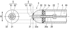
- FIG. 4A and 4B are a front view and a cross-sectional view along the longitudinal direction A of the distal end portion of the treatment instrument 100.
- FIG. The rod 2 penetrates the electrode part 3 along the longitudinal direction A so as to be movable forward and backward.
- the central axis O2 in the longitudinal direction A of the rod 2 substantially coincides with the central axis O1 in the longitudinal direction A of the sheath 1 .
- the rod body 20 is a round bar-shaped member made of a metal material such as stainless steel.
- An insulating coating 20 a is applied to the tip of the rod body 20 .
- An operation wire 4 is attached to the proximal end of the rod body 20 via a stopper 22 .
- the rod body 20 supplies the first electrode 21 with a high-frequency current supplied from the operation wire 4 connected to the operation portion 5 .
- the first electrode 21 is a disc-shaped conductive member provided at the tip of the rod body 20 .
- the outer circumference of the first electrode 21 is formed concentrically with the outer circumference of the rod body 20 when viewed from the front in a direction horizontal to the longitudinal direction A. As shown in FIG.
- the length L1 of the radial direction R perpendicular to the longitudinal direction A of the first electrode 21 is longer than the length L2 of the radial direction R of the rod body 20 .
- the portion where the first electrode 21 and the rod body 20 are exposed from the tip of the second electrode 32 has the function of a high-frequency electrode that applies a high-frequency current to living tissue, and is mainly used for incision and ablation. However, depending on the situation, hemostatic treatment may be performed.
- the first electrode 21 has a first hemostatic treatment surface S1 perpendicular to the longitudinal direction A on the distal end side A1.
- the first hemostatic treatment surface S1 is used for hemostatic treatment with the first electrode 21 and the second electrode 32 in contact with each other.
- the first hemostatic treatment surface S1 may be formed as a flat surface or a curved surface.
- the stopper 22 is provided on the outer periphery of the rod body 20 and the operation wire 4 and connects the rod body 20 and the operation wire 4 . Also, the stopper 22 regulates the length of the rod body 20 exposed from the tip of the second electrode 32 . As a result, the protrusion amount of the first electrode 21 is also regulated. The stopper 22 regulates the projection amount of the first electrode 21 by engaging with the electrode portion 3 provided at the distal end 1a of the sheath 1, as shown in FIG.
- the electrode part 3 is provided at the distal end 1a of the sheath 1.
- the electrode section 3 has a support member 31 and a second electrode 32 .
- the support member 31 is made of a metal material such as stainless steel or an insulating material such as ceramic.
- the support member 31 is a member that is fixed to the distal end 1 a of the sheath 1 and supports the second electrode 32 .
- the support member 31 is fixed to the distal end 1a of the sheath 1 by welding, adhesive, or the like.
- the support member 31 has a through hole 31a through which the rod 2 passes.
- the support member 31 is made of a material harder than the second electrode 32, and makes it easier to deform in the radial direction without moving the second electrode into the sheath 1 when the first electrode is retracted.
- the second electrode 32 is a hollow member having conductivity and elasticity, and is made of conductive silicon rubber, for example.
- the second electrode 32 is fixed to the tip side of the support member 31 by welding, adhesive, or the like.
- the second electrode 32 has a through hole 32b through which the rod 2 passes.
- the second electrode 32 is formed in a hemispherical shape in the absence of external force. Specifically, the second electrode 32 is formed in a hemispherical shape in which the tip side A1 is convex in a state where there is no external force. In the present embodiment, the tip portion 32a that is most convex toward the tip side A1 is located near the central axis O3 in the longitudinal direction A of the second electrode 32. As shown in FIG.
- the through hole 32b opens at the tip portion 32a that is most convex toward the tip side A1. As the second electrode 32 approaches the through hole 32b, the amount of protrusion toward the distal end side A1 increases.
- the through hole 32 b is formed along the central axis O ⁇ b>3 in the longitudinal direction A of the second electrode 32 .
- the length L3 of the through hole 32b in the radial direction R is longer than the length L2 of the rod body 20 in the radial direction R. Therefore, the rod body 20 can move back and forth along the longitudinal direction A through the through hole 32b.
- the movement of the rod 2 to the side A1 of the prior application is referred to as "advance”, and the movement to the base end side A2 is referred to as "retreat”.
- FIG. 5 is a front view and a cross-sectional view along the longitudinal direction A of the distal end portion of the treatment instrument 100 with the second electrode 32 deformed.
- the length L1 of the radial direction R of the first electrode 21 is longer than the length L3 of the radial direction R of the through hole 32b. Therefore, when the second electrode 32 retreats, the second electrode 32 contacts the distal end portion 32a of the second electrode 32 .
- the second electrode 32 contacts the first electrode 21 and deforms. As the first electrode 21 advances away from the second electrode 32, the second electrode 32 returns to its original shape.
- the original shape of the second electrode 32 is also referred to as the “initial shape” of the second electrode 32 .
- An insulating coating 20a is applied to the tip of the rod body 20, and even if the tip of the rod body 20 and the second electrode 32 are in contact with each other, the second electrode 32 is energized from the rod body 20. not.
- the high-frequency current is applied from the first electrode 21 to the second electrode 32 .
- the second electrode 32 has the function of a high-frequency electrode that applies a high-frequency current to living tissue, and mainly performs hemostatic treatment.
- the second electrode 32 is deformed by being pressed by the retreating first electrode 21 .
- the deformed distal end portion 32a of the second electrode 32 has a surface curvature smaller than that of the initial shape.
- a second hemostatic treatment surface S2 having a small curvature is formed on the distal end side A1.
- the first hemostatic treatment surface S1 and the second hemostatic treatment surface S2 form a hemostatic treatment surface S that facilitates hemostatic treatment for the bleeding site arranged in front in the longitudinal direction A.
- the hemostatic treatment surface S preferably forms substantially the same plane or curved surface.
- FIG. 6 is a front view and a cross-sectional view along the longitudinal direction A of the distal end portion of the treatment instrument 100 in a state in which the second electrode 32 is further deformed.
- the second hemostatic treatment surface S2 becomes larger as the contacting first electrode 21 recedes.
- FIG. 7 is a front view and a cross-sectional view along the longitudinal direction A of the distal end portion of the treatment instrument 100 when the second electrode 32 is most deformed.
- the second electrode 32 deforms in the radial direction R until it becomes larger than the sheath 1 when viewed from the front in a direction horizontal to the longitudinal direction A.
- the second hemostatic treatment surface S2 has the smallest curvature and the largest area when the contacting first electrode 21 is most retracted.
- the operation wire 4 is a wire made of a metal material such as stainless steel, and is inserted through the internal space 10 of the sheath 1 .
- a distal end of the operating wire 4 is connected to the rod 2 , and a proximal end of the operating wire 4 is connected to the operating portion 5 .
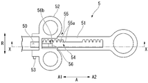
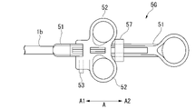
- FIG. 8 is a plan view of the operation unit 5.
- the operation portion 5 has an operation portion main body 51 , a slider 52 , a power supply connector 53 and a lock mechanism 54 .
- the distal end of the operation portion main body 51 is connected to the proximal end 1b of the sheath 1.
- the operation portion main body 51 has an internal space S through which the operation wire 4 can be inserted.
- the operating wire 4 passes through the inner space 10 of the sheath 1 and the inner space 50 of the operating portion main body 51 and extends to the slider 52 .
- the slider 52 is attached to the operation portion main body 51 so as to be movable along the longitudinal direction A.
- a base end portion of the operation wire 4 is connected to the slider 52 .
- the operation wire 4 and the rod 2 move forward and backward relative to the sheath 1 by the operator moving the slider 52 forward and backward relative to the operation portion main body 51 .
- a power supply connector 53 is fixed to the slider 52 .
- the power supply connector 53 can be connected to a high-frequency power supply (not shown), and is electrically and physically connected to the proximal end of the operation wire 4 .
- the power supply connector 53 can supply high-frequency current supplied from the high-frequency power supply to the first electrode 21 via the operation wire 4 and the rod body 20 .
- FIG. 9 is a cross-sectional view of the operating portion 5 taken along line XX in FIG.
- the lock mechanism 54 fixes the position of the slider 52 in the longitudinal direction A, thereby fixing the projecting/retracting position of the rod 2 .
- the lock mechanism 54 has an engaged groove portion 55 and a movable engagement portion 56 .
- the engaged groove portion 55 has a plurality of grooves 55a formed in the operating portion main body 51, as shown in FIGS.
- the groove 55 a is a groove whose depth direction is the width direction B perpendicular to the longitudinal direction A, and is open to the internal space 50 side of the operation portion main body 51 .
- a plurality of grooves 55a are arranged in the longitudinal direction A. As shown in FIG.
- the movable engaging portion 56 is attached to the slider 52 as shown in FIG.
- the movable engaging portion 56 has elasticity and is movable between a first position P1, which is an initial position, and a second position P2 after deformation.
- the movable engaging portion 56 is L-shaped and has a pressing portion 56 a protruding from the slider 52 when viewed from the width direction B perpendicular to the longitudinal direction A from the front.
- FIG. 10 is a cross-sectional view of the operating portion 5 taken along line YY in FIG.
- the movable engaging portion 56 shown in FIG. 10 is in a state where there is no external force, and is arranged at the first position P1, which is the initial position.
- the movable engaging portion 56 has a projecting portion 56b projecting in the width direction B.
- the protruding portion 56b engages with one of the plurality of grooves 55a.
- the position of the slider 52 in the longitudinal direction A of the slider 52 is fixed.
- FIG. 11 is a cross-sectional view of the operating portion 5 taken along line YY in FIG.
- the movable engaging portion 56 shown in FIG. 11 is pushed in by the operator in a direction in which the pressing portion 56a approaches the slider 52, and is arranged at the second position P2.
- the projecting portion 56b does not engage with any of the plurality of grooves 55a.
- the position of the slider 52 in the longitudinal direction A of the slider 52 is not fixed.
- the operator pushes the pressing portion 56a in a direction toward the slider 52 to move the movable engaging portion 56 to the second position P2. After the engagement between the groove 55a and the projecting portion 56b is released (the lock mechanism 54 is released), the operator changes the position of the slider 52 in the longitudinal direction A.
- the operator After changing the position of the slider 52 in the longitudinal direction A, the operator releases the force applied to the pressing portion 56a and returns the movable engaging portion 56 to the first position P1.
- the groove 55a and the projecting portion 56b are engaged to fix the position of the slider 52 in the longitudinal direction A again.
- FIG. 12 shows the treatment instrument 100 to which the slider 52 is fixed on the distal end side.
- the projecting/retracting position of the rod 2 is fixed while the first electrode 21 projects with respect to the second electrode 32 .
- the operator can easily perform incision/ablation treatment using the first electrode 21 fixed in a protruded state.
- FIG. 13 shows the treatment instrument 100 to which the slider 52 is fixed on the base end side.
- the projecting/retracting position of the rod 2 is fixed while the first electrode 21 is in contact with the second electrode 32 .
- the operator uses the hemostatic treatment surface S formed by the first electrode 21 and the second electrode 32 to easily perform hemostatic treatment. Since the projecting/retracting position of the rod 2 is fixed, the size of the hemostatic treatment surface S is maintained.
- the operator identifies the lesion by a known method and bulges the lesion. Specifically, the operator inserts the insertion portion 202 of the endoscope 200 into the digestive tract (e.g., esophagus, stomach, duodenum, large intestine), and observes images obtained by the imaging unit 203 of the endoscope to detect lesions. Identify the part. Next, the operator inserts a known submucosal injection needle into the channel 206 of the insertion portion 202, injects a liquid for local injection (local injection liquid) through the submucosal injection needle, and bulges the lesion. After injecting the local injection solution, the submucosal local injection needle is removed from the channel 206 .
- the digestive tract e.g., esophagus, stomach, duodenum, large intestine
- a known submucosal injection needle into the channel 206 of the insertion portion 202, injects a liquid for local injection (local injection liquid) through the
- the operator inserts the treatment instrument 100 into the channel 206 and protrudes the distal end 1a of the sheath 1 from the distal end opening 206a of the insertion section 202 .
- the operator advances the slider 52 of the operating section 5 relative to the operating section main body 51 to project the rod 2 .
- the operator advances the rod 2 and moves the first electrode 21 while high-frequency current is applied to incise the mucous membrane of the lesion.
- the operator advances the rod 2 to exfoliate the submucosa of the incised lesion while lifting the mucous membrane of the incised lesion and exposing the submucosa while high-frequency current is applied.
- the hemostatic treatment is a treatment for cauterizing an ulcer, an incision, or a bleeding site that bleeds during the ablation treatment to stop bleeding after exfoliating a lesion.
- the operator retracts the rod 2 and brings the first electrode 21 into contact with the second electrode 32 .
- the operator adjusts the size of the hemostatic treatment surface S according to the hemostatic target.
- the rod 2 is retracted until the second hemostasis treated surface S2 is maximized.
- the size of the hemostatic treatment surface S formed by the first hemostatic treatment surface S1 and the second hemostatic treatment surface S2 is adjusted in multiple steps according to the target of hemostatic treatment.
- the second electrode 32 deforms in the radial direction R until it becomes larger than the sheath 1 when viewed from the front in a direction horizontal to the longitudinal direction A. Therefore, even if the hemostatic target is large, the operator can enlarge the hemostatic treatment surface S and suitably perform the hemostatic treatment.
- the operator presses the hemostatic treatment surface S against a bleeding ulcer or mucosal hemostatic target, and energizes the rod 2 with a high-frequency current to cauterize. Since the projecting position of the rod 2 is fixed by the lock mechanism 54 of the operating portion 5, the operator can perform the hemostatic treatment while maintaining the size of the hemostatic treatment surface S. Therefore, it is possible to suitably prevent a situation in which a site that does not require hemostasis is cauterized.
- the treatment instrument 100 it is possible to perform incision/stripping treatment and hemostatic treatment, and to perform suitable hemostatic treatment according to the size of the bleeding site.
- the operator can easily perform hemostatic treatment without using a treatment instrument dedicated to hemostatic treatment.
- the operator can accurately cauterize the hemostatic target with the hemostatic treatment surface S adjusted in multiple stages according to the hemostatic target.
- the endoscope 200 is a flexible endoscope.
- the treatment instrument 100 may be used as an endoscopic treatment system together with a rigid endoscope.
- the tip of the rod body 20 is coated with an insulating coating 20a, and when the first electrode 21 is not in contact with the second electrode 32, the rod 2 does not energize the second electrode 32.
- the insulation mode between the rod body 20 and the second electrode 32 is not limited to this.
- the insulating coating 20a may not be applied to the rod body 20, and the inner peripheral surface of the through hole 32b of the second electrode 32 may be provided with an insulating coating.
- the rod 2 passes through the second electrode 32 .
- the aspect of the rod 2 and the second electrode 32 is not limited to this. As long as the retreating rod 2 can deform the second electrode 32 , the rod 2 does not have to penetrate the second electrode 32 .
- FIG. 14 to 15 A treatment instrument 100B according to a second embodiment of the present invention will be described with reference to FIGS. 14 to 15.
- FIG. 14 to 15 the same reference numerals are given to the same configurations as those already described, and redundant descriptions will be omitted.
- the treatment instrument 100B is used as an endoscope treatment system together with the endoscope 200, like the treatment instrument 100 of the first embodiment.
- the treatment instrument 100B is a treatment instrument capable of performing an incision/stripping treatment and a hemostatic treatment.
- the treatment instrument 100B includes a sheath 1, a rod 2, an electrode section 3B, an operating wire 4, and an operating section 5.
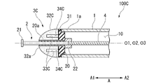
- FIG. 14 is a perspective view of the distal end portion of the treatment instrument 100B.
- the electrode portion 3B is provided at the distal end 1a of the sheath 1. As shown in FIG.
- the electrode section 3B has a support member 31 and a second electrode 32B.
- FIG. 15 is a cross-sectional view along the longitudinal direction A of the distal end portion of the treatment instrument 100B.
- the second electrode 32B is a solid member having conductivity and elasticity.
- the second electrode 32B is fixed to the tip side of the support member 31 by welding, adhesive, or the like.
- the second electrode 32B has a through hole 32b through which the rod 2 passes, and a slit 33B.
- the second electrode 32B is formed in a hemispherical shape when there is no external force.
- the second electrode 32B is formed in a hemispherical shape in which the tip side A1 is convex in a state where there is no external force.
- the tip portion 32a that is most convex toward the tip side A1 is located near the central axis O3 in the longitudinal direction A of the second electrode 32B.
- the slit 33B is a cut provided inside the second electrode 32B, as shown in FIG.
- the slit 33B is formed over the entire circumference in the circumferential direction C with the central axis O3 in the longitudinal direction A of the second electrode 32B as the center of rotation.
- the slit 33B is an isosceles triangular incision with the tip side A1 as the apex angle in the cross section along the longitudinal direction A.
- the slit 33B is open on the base end side A2 of the second electrode 32B.
- An internal space 34B defined by the slit 33B is formed inside the second electrode 32B.
- the second electrode 32B is deformed by being pressed by the retreating first electrode 21, like the second electrode 32 of the first embodiment.
- the second electrode 32B has an internal space 34B formed by a slit 33B on the proximal side A2, and the second electrode 32B on the proximal side A2 is soft. . Therefore, the base end side of the second electrode 32B is more easily deformed than the second electrode 32 of the first embodiment.
- the second electrode 32B tends to expand in the radial direction R when pressed from the distal end side. Since the second electrode 32B is easily changed in the radial direction R, it is easier for the operator to adjust the size of the hemostatic treatment surface S.
- the treatment instrument 100B it is possible to perform incision/stripping treatment and hemostatic treatment, and to perform suitable hemostatic treatment according to the size of the bleeding site.
- the operator can easily perform hemostatic treatment without using a treatment instrument dedicated to hemostatic treatment.
- the operator can accurately cauterize the hemostatic target with the hemostatic treatment surface S adjusted in multiple stages according to the hemostatic target.
- the slit 33B is an isosceles triangular incision in the cross section along the longitudinal direction A with the tip side A1 as the apex angle.
- the aspect of the second electrode 32B provided with the slit 33B is not limited to this.
- a treatment instrument 100C shown in FIG. 16 is a cross-sectional view along the longitudinal direction A of a second electrode 32C, which is a modified example of the second electrode 32B.
- the second electrode 32C has a slit 33C instead of the slit 33B.
- the slit 33C is a notch provided inside the second electrode 32C.
- the slit 33C is formed over the entire circumference in the circumferential direction C with the central axis O3 in the longitudinal direction A of the second electrode 32C as the center of rotation.
- the slit 33C is a rectangular cut in a cross section along the longitudinal direction A.
- the slit 33C is open on the base end side A2 of the second electrode 32C.
- An internal space 34C defined by the slit 33C is formed inside the second electrode 32C.
- the slit 33C is easier to process than the slit 33B.
- a treatment instrument 100D according to a third embodiment of the present invention will be described with reference to FIG.
- the same reference numerals are given to the same configurations as those already described, and redundant descriptions will be omitted.
- the treatment instrument 100D is used as an endoscope treatment system together with the endoscope 200, like the treatment instrument 100 of the first embodiment.
- the treatment instrument 100D is a treatment instrument capable of performing an incision/stripping treatment and a hemostatic treatment.
- the treatment instrument 100 ⁇ /b>D includes a sheath 1 , a rod 2 , an electrode section 3 ⁇ /b>D, an operating wire 4 and an operating section 5 .
- FIG. 17 is a cross-sectional view along the longitudinal direction A of the distal end portion of the treatment instrument 100D.
- the electrode portion 3D is provided at the distal end 1a of the sheath 1.
- the electrode section 3D has a support member 31 and a second electrode 32D.
- the second electrode 32D is a hollow member having conductivity and elasticity. An internal space 34D is formed inside the second electrode 32D.
- the second electrode 32D is fixed to the tip side of the support member 31 by welding, adhesive, or the like.
- the second electrode 32D has a through hole 32b through which the rod 2 passes.
- the internal space 34D is formed in a cylindrical shape with the central axis O3 in the longitudinal direction A of the second electrode 32C as the central axis.
- a length L4 of the radial direction R of the internal space 34D is longer than a length L1 of the radial direction R of the first electrode 21 .
- the through hole 32b is formed on the tip side A1 from the internal space 34D.
- the rod body 20 penetrates the internal space 34D and the through hole 32b, as shown in FIG.
- the second electrode 32D is deformed by being pressed by the retreating first electrode 21, like the second electrode 32 of the first embodiment.
- the second electrode 32D is softer than the second electrode 32 of the first embodiment because the second electrode 32D is a hollow member and has an internal space 34D. Therefore, the second electrode 32D makes it easier to retract the rod 2 than the second electrode 32 of the first embodiment. Therefore, the operator can easily adjust the size of the hemostatic treatment surface S.
- the treatment instrument 100D it is possible to perform incision/stripping treatment and hemostatic treatment, and to perform suitable hemostatic treatment according to the size of the bleeding site.
- the operator can easily perform hemostatic treatment without using a treatment instrument dedicated to hemostatic treatment.
- the operator can accurately cauterize the hemostatic target with the hemostatic treatment surface S adjusted in multiple stages according to the hemostatic target.
- the internal space 34D of the second electrode 32D which is a hollow member, is formed in a cylindrical shape.
- the shape of the internal space 34D is not limited to this.
- the internal space 34D may have, for example, a hemispherical shape similar to the hemispherical shape of the second electrode 32D.
- FIG. 18 A treatment instrument 100E according to a fourth embodiment of the present invention will be described with reference to FIGS. 18 to 19.
- FIG. 18 the same reference numerals are given to the same configurations as those already described, and redundant descriptions will be omitted.
- the treatment instrument 100E is used as an endoscope treatment system together with the endoscope 200, like the treatment instrument 100 of the first embodiment.
- the treatment instrument 100E is a treatment instrument capable of performing incision/stripping treatment and hemostatic treatment.
- the treatment instrument 100 ⁇ /b>E includes a sheath 1 , a rod 2 , an electrode section 3 ⁇ /b>E, an operating wire 4 and an operating section 5 .
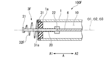
- FIG. 18 is a cross-sectional view along the longitudinal direction A of the distal end portion of the treatment instrument 100E.
- the electrode portion 3E is provided at the distal end 1a of the sheath 1.
- the electrode section 3E has a support member 31, a second electrode 32, and a reinforcing electrode 36. As shown in FIG.
- the reinforcing electrode 36 is made of a conductive metal material such as stainless steel, and is harder than the second electrode 32 .
- the reinforcing electrode 36 is provided on the tip of the second electrode 32 and the inner peripheral surface of the through hole 32 b of the second electrode 32 .
- the second electrode 32 and the reinforcing electrode 36 are connected by welding, adhesive, or the like.
- FIG. 19 is a cross-sectional view along the longitudinal direction A of the treatment instrument 100E in a state where the second electrode 32 is deformed by the retracted first electrode 21.
- FIG. The second electrode 32 is deformed by being pressed by the retreating first electrode 21, like the second electrode 32 of the first embodiment. Since the reinforcing electrode 36 is provided at the tip of the second electrode 32E, the second electrode 32 is pressed by the reinforcing electrode 36 in contact with the retreating first electrode 21 and deformed.
- a second hemostatic treatment surface S2 is formed on the distal end side A1 of the second electrode 32E.
- the hard reinforcing electrode 36 is provided on the tip of the second electrode 32 and the inner peripheral surface of the through hole 32b of the second electrode 32, the force with which the first electrode 21 pushes the second electrode 32 becomes more uniform. Therefore, the deformed second electrode 32 tends to change into a shape symmetrical with respect to the central axis O3 when viewed in the longitudinal direction A, and the operator can easily adjust the size of the hemostatic treatment surface S.
- the high-frequency current is applied from the first electrode 21 to the second electrode 32.
- the treatment instrument 100E it is possible to perform incision/stripping treatment and hemostatic treatment, and to perform suitable hemostatic treatment according to the size of the bleeding site.
- the operator can easily perform hemostatic treatment without using a treatment instrument dedicated to hemostatic treatment.
- the operator can accurately cauterize the hemostatic target with the hemostatic treatment surface S adjusted in multiple stages according to the hemostatic target.
- FIG. 20 to 22 A treatment instrument 100F according to a fifth embodiment of the present invention will be described with reference to FIGS. 20 to 22.
- FIG. 20 to 22 the same reference numerals are given to the same configurations as those already described, and redundant descriptions will be omitted.
- the treatment instrument 100F is used as an endoscope treatment system together with the endoscope 200, like the treatment instrument 100 of the first embodiment.
- the treatment instrument 100F is a treatment instrument that can perform incision/ablation treatment and hemostatic treatment.
- the treatment instrument 100 ⁇ /b>F includes a sheath 1 , a rod 2 , an electrode section 3 ⁇ /b>F, an operating wire 4 and an operating section 5 .
- the 20A and 20B are a front view and a cross-sectional view along the longitudinal direction A of the distal end portion of the treatment instrument 100F.
- the electrode portion 3 ⁇ /b>F is provided at the distal end 1 a of the sheath 1 .
- the electrode section 3F has a support member 31 and a second electrode 32F.
- the rod 2 penetrates the second electrode 32F along the central axis of the second electrode 32F.
- the second electrode 32F is a conical coil spring (cob spring) made of a conductive metal material such as stainless steel.
- the second electrode 32F is formed in a conical shape with an outer diameter decreasing from the base end side to the tip end side.
- the second electrode 32F has a spiral shape in which the second electrodes 32F do not overlap each other when viewed from the longitudinal direction A from the front.
- the second electrode 32F may be made of conductive rubber.
- FIG. 21 is a cross-sectional view along the longitudinal direction A of the distal end portion of the treatment instrument 100F in a state where the second electrode 32F has started to deform.
- the second electrode 32F shrinks by being pressed by the retreating first electrode 21, like the second electrode 32 of the first embodiment.
- a second hemostatic treatment surface S2 is formed on the distal end side A1 of the second electrode 32F.
- FIG. 22 is a cross-sectional view along the longitudinal direction A of the distal end portion of the treatment instrument 100F in a state where the second electrode 32F is further deformed.
- the second electrode 32F shown in FIG. 22 is in the most contracted state in the longitudinal direction A.
- the second electrode 32F has a spiral shape in which the second electrodes 32F do not overlap each other when viewed from the longitudinal direction A from the front. Therefore, when the second electrode 32F is most contracted in the longitudinal direction A, the second hemostatic treatment surface S2 becomes substantially flat and is suitable as a surface for performing hemostatic treatment.
- the high-frequency current is applied from the first electrode 21 to the second electrode 32F.
- the treatment instrument 100F it is possible to perform incision/stripping treatment and hemostatic treatment, and suitable hemostatic treatment according to the size of the bleeding site.
- the operator can easily perform hemostatic treatment without using a treatment instrument dedicated to hemostatic treatment.
- the operator can accurately cauterize the hemostatic target with the hemostatic treatment surface S adjusted in multiple stages according to the hemostatic target.
- FIG. 23 A treatment instrument 100G according to a sixth embodiment of the present invention will be described with reference to FIGS. 23 to 25.
- FIG. 23 the same reference numerals are given to the same configurations as those already described, and redundant descriptions will be omitted.
- [Treatment instrument 100G] 100 G of treatment tools are used as an endoscope treatment system with the endoscope 200 like the treatment tool 100 of 1st embodiment.
- the treatment instrument 100G is a treatment instrument capable of performing incision/stripping treatment and hemostatic treatment.
- the treatment instrument 100G includes a sheath 1, a rod 2, an electrode section 3, an operating wire 4, and an operating section 5G.
- the operation portion 5G has an operation portion main body 51, a slider 52, a power supply connector 53, a lock mechanism 54, and a second lock mechanism 57.
- FIG. 23 is a perspective view of the second lock mechanism 57 of the operation portion 5G.
- the second lock mechanism 57 is a member that can be attached to and detached from the operation portion main body 51 .
- the second lock mechanism 57 is formed in a U shape. Both ends of the second lock mechanism 57 are formed with return portions 57a.
- FIG. 24 is a diagram showing the operating portion 5G in which the position of the slider 52 is fixed to the distal end side A1 by the second locking mechanism 57.
- FIG. FIG. 25 is a diagram showing the operating portion 5G in which the position of the slider 52 is fixed to the base end side A2 by the second locking mechanism 57.
- the second lock mechanism 57 is attached to the operating portion main body 51
- the return portion 57 a engages with the operating portion main body 51 and is fixed to the operating portion main body 51 . Therefore, the second lock mechanism 57 is attached to the operation portion main body 51 to restrict forward and backward movement of the slider 52 .
- the protruded and retracted position of the rod 2 is more reliably fixed while the first electrode 21 protrudes from the second electrode 32.
- the operator can easily perform incision/ablation treatment using the first electrode 21 fixed in a protruded state.
- the treatment instrument 100G it is possible to perform incision/stripping treatment and hemostatic treatment, and to perform suitable hemostatic treatment according to the size of the bleeding site.
- the operator can easily perform hemostatic treatment without using a treatment instrument dedicated to hemostatic treatment.
- the operator can accurately cauterize the hemostatic target with the hemostatic treatment surface S adjusted in multiple stages according to the hemostatic target.
- the present invention can be applied to treatment tools used for hemostatic treatment.
- endoscope treatment system 200 endoscope 100, 100B, 100C, 100D, 100E, 100F, 100G treatment instrument 1 sheath 2 rod 20 rod body 20a insulating coating 21 first electrode 22 stoppers 3, 3B, 3D, 3E, 3F Electrode part 31 Support member 31b Through holes 32, 32B, 32C, 32D, 32F Second electrode 32a Tip part 32b Through holes 33B, 33C Slits 34B, 34C, 34D Internal space 36 Reinforcing electrode 4 Operation wires 5, 5G Operation part 51 Operation Main body 52 Slider 54 Lock mechanism 57 Second lock mechanism
Landscapes
- Health & Medical Sciences (AREA)
- Surgery (AREA)
- Engineering & Computer Science (AREA)
- Life Sciences & Earth Sciences (AREA)
- Biomedical Technology (AREA)
- Otolaryngology (AREA)
- Nuclear Medicine, Radiotherapy & Molecular Imaging (AREA)
- Plasma & Fusion (AREA)
- Physics & Mathematics (AREA)
- Heart & Thoracic Surgery (AREA)
- Medical Informatics (AREA)
- Molecular Biology (AREA)
- Animal Behavior & Ethology (AREA)
- General Health & Medical Sciences (AREA)
- Public Health (AREA)
- Veterinary Medicine (AREA)
- Surgical Instruments (AREA)
Abstract
Priority Applications (3)
| Application Number | Priority Date | Filing Date | Title |
|---|---|---|---|
| CN202180091200.0A CN116710015A (zh) | 2021-01-25 | 2021-01-25 | 处置器具 |
| PCT/JP2021/002453 WO2022157977A1 (fr) | 2021-01-25 | 2021-01-25 | Instrument |
| JP2022576939A JPWO2022157977A1 (fr) | 2021-01-25 | 2021-01-25 |
Applications Claiming Priority (1)
| Application Number | Priority Date | Filing Date | Title |
|---|---|---|---|
| PCT/JP2021/002453 WO2022157977A1 (fr) | 2021-01-25 | 2021-01-25 | Instrument |
Publications (1)
| Publication Number | Publication Date |
|---|---|
| WO2022157977A1 true WO2022157977A1 (fr) | 2022-07-28 |
Family
ID=82548658
Family Applications (1)
| Application Number | Title | Priority Date | Filing Date |
|---|---|---|---|
| PCT/JP2021/002453 WO2022157977A1 (fr) | 2021-01-25 | 2021-01-25 | Instrument |
Country Status (3)
| Country | Link |
|---|---|
| JP (1) | JPWO2022157977A1 (fr) |
| CN (1) | CN116710015A (fr) |
| WO (1) | WO2022157977A1 (fr) |
Citations (3)
| Publication number | Priority date | Publication date | Assignee | Title |
|---|---|---|---|---|
| JPH0380847A (ja) * | 1989-08-22 | 1991-04-05 | Olympus Optical Co Ltd | 高周波処置用患者電極 |
| JP2010505552A (ja) * | 2006-10-05 | 2010-02-25 | スピネイカー メディカル エルエルシー | 電気外科的装置 |
| WO2019016941A1 (fr) * | 2017-07-21 | 2019-01-24 | オリンパス株式会社 | Manipulateur médical |
-
2021
- 2021-01-25 JP JP2022576939A patent/JPWO2022157977A1/ja active Pending
- 2021-01-25 CN CN202180091200.0A patent/CN116710015A/zh active Pending
- 2021-01-25 WO PCT/JP2021/002453 patent/WO2022157977A1/fr active Application Filing
Patent Citations (3)
| Publication number | Priority date | Publication date | Assignee | Title |
|---|---|---|---|---|
| JPH0380847A (ja) * | 1989-08-22 | 1991-04-05 | Olympus Optical Co Ltd | 高周波処置用患者電極 |
| JP2010505552A (ja) * | 2006-10-05 | 2010-02-25 | スピネイカー メディカル エルエルシー | 電気外科的装置 |
| WO2019016941A1 (fr) * | 2017-07-21 | 2019-01-24 | オリンパス株式会社 | Manipulateur médical |
Also Published As
| Publication number | Publication date |
|---|---|
| CN116710015A (zh) | 2023-09-05 |
| JPWO2022157977A1 (fr) | 2022-07-28 |
Similar Documents
| Publication | Publication Date | Title |
|---|---|---|
| KR100595803B1 (ko) | 고주파 나이프 및 내시경 장치 | |
| US7731714B2 (en) | Instrument for endoscope and instrument system for endoscope | |
| US8192431B2 (en) | Endoscopic treatment instrument | |
| US7125408B2 (en) | High-frequency knife | |
| US7371236B2 (en) | Diathermic cutter | |
| US20090254085A1 (en) | Treatment instrument for endoscope | |
| US20040210284A1 (en) | Radio knife | |
| US20090254084A1 (en) | High-frequency treatment apparatus | |
| US20210077179A1 (en) | Multifunctional high-frequency electric knife | |
| US20080275444A1 (en) | Endoscopic treatment instrument and tissue incision method | |
| US20220022956A1 (en) | Endoscope snare | |
| JP7467707B2 (ja) | 内視鏡用処置具 | |
| WO2022157977A1 (fr) | Instrument | |
| JP7301184B2 (ja) | 内視鏡用術具 | |
| JP7459311B2 (ja) | 処置具 | |
| JP7439550B2 (ja) | 内視鏡用針状メス | |
| WO2024202400A1 (fr) | Outil de traitement pour endoscope | |
| JP2024097765A (ja) | 内視鏡用処置具、内視鏡用処置具システムおよび内視鏡用処置具の操作方法 | |
| US20230136593A1 (en) | Treatment tool for endoscope | |
| CN217338657U (zh) | 内窥镜用处置器具 | |
| JP7250639B2 (ja) | 内視鏡用高周波ナイフ装置 | |
| US20230240514A1 (en) | Endoscopic treatment tool | |
| KR101750654B1 (ko) | 내시경 점막하 박리술에 이용되는 나이프 |
Legal Events
| Date | Code | Title | Description |
|---|---|---|---|
| 121 | Ep: the epo has been informed by wipo that ep was designated in this application |
Ref document number: 21921085 Country of ref document: EP Kind code of ref document: A1 |
|
| WWE | Wipo information: entry into national phase |
Ref document number: 202180091200.0 Country of ref document: CN |
|
| ENP | Entry into the national phase |
Ref document number: 2022576939 Country of ref document: JP Kind code of ref document: A |
|
| NENP | Non-entry into the national phase |
Ref country code: DE |
|
| 122 | Ep: pct application non-entry in european phase |
Ref document number: 21921085 Country of ref document: EP Kind code of ref document: A1 |