WO2015099100A1 - リアクトル - Google Patents
リアクトル Download PDFInfo
- Publication number
- WO2015099100A1 WO2015099100A1 PCT/JP2014/084436 JP2014084436W WO2015099100A1 WO 2015099100 A1 WO2015099100 A1 WO 2015099100A1 JP 2014084436 W JP2014084436 W JP 2014084436W WO 2015099100 A1 WO2015099100 A1 WO 2015099100A1
- Authority
- WO
- WIPO (PCT)
- Prior art keywords
- coil
- adhesive layer
- reactor
- core portion
- inner core
- Prior art date
- Legal status (The legal status is an assumption and is not a legal conclusion. Google has not performed a legal analysis and makes no representation as to the accuracy of the status listed.)
- Ceased
Links
Images









Classifications
-
- H—ELECTRICITY
- H01—ELECTRIC ELEMENTS
- H01F—MAGNETS; INDUCTANCES; TRANSFORMERS; SELECTION OF MATERIALS FOR THEIR MAGNETIC PROPERTIES
- H01F27/00—Details of transformers or inductances, in general
- H01F27/08—Cooling; Ventilating
- H01F27/10—Liquid cooling
-
- H—ELECTRICITY
- H01—ELECTRIC ELEMENTS
- H01F—MAGNETS; INDUCTANCES; TRANSFORMERS; SELECTION OF MATERIALS FOR THEIR MAGNETIC PROPERTIES
- H01F27/00—Details of transformers or inductances, in general
- H01F27/02—Casings
- H01F27/025—Constructional details relating to cooling
-
- H—ELECTRICITY
- H01—ELECTRIC ELEMENTS
- H01F—MAGNETS; INDUCTANCES; TRANSFORMERS; SELECTION OF MATERIALS FOR THEIR MAGNETIC PROPERTIES
- H01F27/00—Details of transformers or inductances, in general
- H01F27/24—Magnetic cores
- H01F27/26—Fastening parts of the core together; Fastening or mounting the core on casing or support
- H01F27/263—Fastening parts of the core together
-
- H—ELECTRICITY
- H01—ELECTRIC ELEMENTS
- H01F—MAGNETS; INDUCTANCES; TRANSFORMERS; SELECTION OF MATERIALS FOR THEIR MAGNETIC PROPERTIES
- H01F27/00—Details of transformers or inductances, in general
- H01F27/28—Coils; Windings; Conductive connections
- H01F27/29—Terminals; Tapping arrangements for signal inductances
-
- H—ELECTRICITY
- H01—ELECTRIC ELEMENTS
- H01F—MAGNETS; INDUCTANCES; TRANSFORMERS; SELECTION OF MATERIALS FOR THEIR MAGNETIC PROPERTIES
- H01F27/00—Details of transformers or inductances, in general
- H01F27/28—Coils; Windings; Conductive connections
- H01F27/30—Fastening or clamping coils, windings, or parts thereof together; Fastening or mounting coils or windings on core, casing, or other support
- H01F27/306—Fastening or mounting coils or windings on core, casing or other support
-
- H—ELECTRICITY
- H01—ELECTRIC ELEMENTS
- H01F—MAGNETS; INDUCTANCES; TRANSFORMERS; SELECTION OF MATERIALS FOR THEIR MAGNETIC PROPERTIES
- H01F37/00—Fixed inductances not covered by group H01F17/00
-
- H—ELECTRICITY
- H01—ELECTRIC ELEMENTS
- H01F—MAGNETS; INDUCTANCES; TRANSFORMERS; SELECTION OF MATERIALS FOR THEIR MAGNETIC PROPERTIES
- H01F27/00—Details of transformers or inductances, in general
- H01F27/40—Structural association with built-in electric component, e.g. fuse
- H01F27/402—Association of measuring or protective means
- H01F2027/406—Temperature sensor or protection
Definitions
- the present invention relates to a reactor used as a component part of a power conversion device such as a vehicle-mounted DC-DC converter mounted on a vehicle such as a hybrid vehicle.
- the present invention relates to a reactor that can suppress movement of a coil accompanying vibration during operation while improving heat dissipation.
- Reactor is one of the circuit components that perform voltage step-up and step-down operations.
- the reactor is used in a converter mounted on a vehicle such as a hybrid vehicle.
- a vehicle such as a hybrid vehicle.
- the reactor for example, there is one shown in Patent Document 1.
- the reactor of Patent Document 1 is configured such that an assembly of a coil molded body obtained by integrally molding a part of a coil and an annular core with an inner resin portion and the remaining portion of the core is covered with an outer resin portion.
- a coated rectangular wire obtained by enamelling a copper rectangular wire is used as the coil.
- the reactor is housed and fixed in a housing part through which liquid refrigerant is circulated. And a reactor is cooled by distribute
- the entire circumference of the coil is covered with an inner resin part and an outer resin part integral with the core, and the coil and the liquid refrigerant do not come into direct contact. Therefore, it is desired to further enhance the heat dissipation effect by the liquid refrigerant with respect to the reactor. If the inner resin portion and the outer resin portion are omitted, heat dissipation can be improved, but the coil and the core are in an unfixed state. Then, the coil moves in the coil axial direction, the radial direction, and the circumferential direction due to the vibration of the coil and the core during the reactor operation or the influence from the external environment.
- the coil and the core collide or rub, and adjacent turns forming the coil collide or rub against each other, increasing noise.
- the coil is composed of a coated wire, there is a risk that the enamel coating of the coil may be damaged due to the collision and rubbing between the coil and the core and the collision or rubbing between the turns.
- the present invention has been made in view of the above circumstances, and one of its purposes is to provide a reactor capable of suppressing the movement of a coil accompanying vibration during operation while improving heat dissipation.
- a reactor includes a coil formed by winding a winding, an inner core portion disposed inside the coil, and an outer core connected to the inner core portion to form a closed magnetic circuit together with the inner core portion.
- a magnetic core having a portion.
- the outer core portion includes a side main body portion serving as a magnetic path.
- the side main body portion has a facing surface including an inner core facing region facing the inner core portion and a coil facing region facing the end surface of the coil.
- the reactor is interposed between a portion of the inner circumferential surface of the coil in the circumferential direction and the inner core portion, and between at least one of the end surface of the coil and the coil facing region, and the inner core portion and the outer core.
- An adhesive layer that fixes at least one of the parts and the coil.
- the above reactor can suppress the movement of the coil due to vibration during operation while improving heat dissipation.
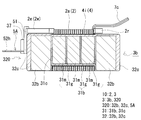
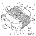
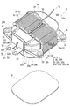
- FIG. 1 is a schematic perspective view showing a reactor according to Embodiment 1.
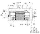
- FIG. FIG. 2 is a (II)-(II) cross-sectional view of the reactor shown in FIG.
- FIG. 3 is a (III)-(III) cross-sectional view of the reactor shown in FIG.
- It is a disassembled perspective view which shows the outline of the union body with which the reactor of Embodiment 1 is equipped.
- It is a schematic explanatory drawing which shows the use condition of the reactor of Embodiment 1.
- It is a schematic perspective view which shows the reactor which concerns on Embodiment 2.
- FIG. It is a disassembled perspective view which shows the outline of the union body with which the reactor which concerns on Embodiment 2 is equipped.
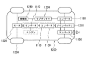
- FIG. 1 is a schematic configuration diagram schematically showing a power supply system of a hybrid vehicle. It is a schematic circuit diagram which shows an example of a power converter device provided with a converter.
- a reactor includes a coil formed by winding a winding, an inner core portion disposed inside the coil, and an outer core connected to the inner core portion to form a closed magnetic circuit together with the inner core portion.
- a magnetic core having a portion.
- the outer core portion includes a side main body portion serving as a magnetic path.
- the side main body portion has a facing surface including an inner core facing region facing the inner core portion and a coil facing region facing the end surface of the coil.
- the reactor is interposed between a portion of the inner circumferential surface of the coil in the circumferential direction and the inner core portion, and between at least one of the end surface of the coil and the coil facing region, and the inner core portion and the outer core.
- An adhesive layer that fixes at least one of the parts and the coil.
- the movement of the coil accompanying vibration during operation can be suppressed while improving heat dissipation. Details will be described later.
- the adhesive layer is interposed between a part of the inner peripheral surface of the coil in the circumferential direction and the inner core portion, and an inner adhesive layer that fixes the coil and the inner core portion is provided. Preparation.
- the coil and the inner core portion are not fixed by the resin that covers the entire circumference of the coil integrally with the magnetic core as in the prior art, but between the inner peripheral surface of the coil and the inner core portion. It is performed by an inner adhesive layer interposed therebetween. Therefore, the outer peripheral surface of a coil can be exposed and the heat dissipation of a reactor can be improved.
- the reactor when the reactor is disposed at a location where the liquid refrigerant is circulated, the liquid refrigerant and the coil can be brought into direct contact with each other. Therefore, the heat dissipation of the coil, and thus the heat dissipation of the reactor can be improved more effectively.
- the axis of the coil accompanying the influence of the vibration of the coil or the magnetic core during the operation of the reactor or the external environment (for example, the liquid refrigerant). Movement in the direction, radial direction, and circumferential direction can be suppressed. Therefore, the collision and rubbing between the coil and the magnetic core and the collision and rubbing between the turns of the coil can be suppressed. Therefore, it is possible to reduce noise accompanying the collision and rubbing and damage to the coil insulation coating.
- the inner adhesive layer is formed at a part in the circumferential direction of the coil and at least a part in the axial direction of the coil, for example. Easy to insert through.
- the inner adhesive layer is provided on the end side of the winding in the coil.
- the end portion side of the winding in the turn forming portion of the coil moves in the axial direction, the radial direction, and the circumferential direction, the end portion of the winding tends to follow the movement.
- a terminal fitting to which an external device such as a power source for supplying power to the coil is connected is connected to the end of the winding.
- the terminal fitting is fixed to a terminal block or the like. For this reason, when the coil moves, excessive stress is applied to the connection portion between the end of the winding and the terminal fitting due to the movement.
- the inner side adhesive layer is provided in the coil end part side among coils, the movement of the said end part side of a turn formation part can be suppressed, and the coil of the edge part of a coil
- the inner peripheral surface of the coil and the surface of the inner core portion that are in contact with the inner adhesive layer are configured to be flat.
- the inner peripheral surface of a coil and the surface of an inner core part which an inner side adhesive layer contacts are comprised by the plane, the inner side adhesive layer in which the thickness of an inner side adhesive layer is equal over the whole region is formed. easy. Therefore, it is easy to fix the coil and the inner core portion uniformly over the entire inner adhesive layer, and it is easier to more firmly fix the coil and the inner core portion.
- the inner adhesive layer is interposed at least in part between the turns of the coil.
- the interval between the turns of the coil can be fixed, and the collision and rubbing between the turns can be further suppressed.
- the adhesive layer is interposed between the end face of the coil and the coil facing region, and includes an end adhesive layer that fixes the coil and the outer core part. It is done.
- the coil and the outer core portion are not fixed with the resin that covers the entire circumference of the coil integrally with the magnetic core as in the conventional case, but between the end surface of the coil and the outer core portion. This is done by the interposing end adhesive layer. Therefore, the outer peripheral surface of a coil can be exposed and the heat dissipation of a reactor can be improved.
- the reactor when the reactor is disposed at a location where the liquid refrigerant is circulated, the liquid refrigerant and the coil can be brought into direct contact with each other. Therefore, the heat dissipation of the coil, and thus the heat dissipation of the reactor can be improved more effectively.
- work of the constituent material of an edge part adhesive layer is simple by making the formation location of an edge part adhesive layer into at least one part of the said opposing surface.
- the outer core portion may include a side resin mold portion that covers at least a part of the outer periphery of the side main body portion and insulates the side main body portion and the coil.
- the side resin mold portion has an intervening region interposed between the side main body portion and the end portion adhesive layer.
- the insulation between a side main-body part and a coil is securable by providing the side resin mold part which has the said interposition area
- the surface facing the coil in the intervening area may be configured with an inclined surface corresponding to the form of the end face of the coil. At this time, the thickness of the intervening region is increased along the inclination of the end surface of the coil as the end surface of the coil is separated from the coil facing region.
- the thickness of the end adhesive layer can be made uniform over the entire area. Therefore, it is easy to make the adhesive strength between the coil and the outer core portion uniform over the entire end adhesive layer, and it is easy to firmly fix the coil and the outer core portion.
- a fixed coating layer that is formed along at least a part in the axial direction of the coil and that fixes the interval between the turns of the coil is provided on a part of the outer circumferential surface of the coil.
- the interval between the turns of the coil can be fixed while increasing the exposed area of the outer peripheral surface of the coil, and the collision and rubbing of the turns can be further suppressed.
- the adhesive layer is composed of an ultraviolet curable adhesive.
- the ultraviolet curable adhesive is cured by irradiation with ultraviolet rays, it is not necessary to heat the adhesive layer at a higher temperature than the thermosetting adhesive when forming the adhesive layer. Further, since the ultraviolet curable adhesive does not cure unless it is irradiated with ultraviolet rays, there are few restrictions on the time until curing, for example, when the adhesive layer is formed. Furthermore, since the curing speed is relatively fast, it is easy to shorten the formation time of the adhesive layer, and hence the production time of the reactor.
- the inner core portion includes a middle main body portion serving as a magnetic path, and a middle resin mold that covers at least a part of the outer periphery of the middle main body portion and insulates the middle main body portion and the coil. A part.
- the middle resin mold portion by providing the middle resin mold portion, it is possible to ensure insulation between the middle main body portion and the coil. Further, since the middle main body can be protected from the external environment, the middle main body is hardly damaged by a physical impact. Furthermore, when this reactor is arrange
- the outer core part may include a terminal fitting and a side resin mold part in addition to the side main body part.
- the terminal fitting is connected to the end of the coil winding.
- the side resin mold part covers at least a part of the outer periphery of the side main body part, insulates the side main body part and the coil, and between the side main body part and the terminal metal fitting, and between the side main body part and the terminal metal fitting. Hold it together.
- the insulation between a side main-body part and a coil, and a side main-body part and a terminal metal fitting is securable by providing a side resin mold part. Further, since the side main body portion can be protected from the external environment, the side main body portion is hardly damaged by a physical impact. Furthermore, when this reactor is arrange
- the reactor it is possible to include a case in which an assembly of a coil and a magnetic core is housed and a liquid refrigerant is supplied and discharged.
- the entire circumference of the coil is not covered with resin as in the prior art, and the coil can be cooled by being brought into direct contact with the liquid refrigerant, so that the heat dissipation of the reactor can be improved.
- the case can control the flow of the liquid refrigerant that cools the combination by supplying and discharging the liquid refrigerant, and can effectively cool the combination.
- the coil and the core are fixed by the above-described adhesive layer, even when the liquid refrigerant is applied to the coil, movement and deformation in the axial direction, radial direction, and circumferential direction of the coil can be suppressed. Therefore, the collision and rubbing between the coil and the core, the collision and rubbing between the turns of the coil can be suppressed, and noise can be reduced.
- the coil is composed of a covered wire, damage to the covered wire can be suppressed.
- Embodiment 1 [Overall structure of the reactor] A reactor 1A according to the first embodiment will be described with reference to FIGS.
- the reactor 1A will be described in detail in the state of use of the reactor 1A, which will be described later.
- the reactor 1A is disposed and used at a location that is directly exposed to a liquid refrigerant.
- 1 A of reactors are provided with the combination 10 of the coil 2 and the magnetic core 3 which is arrange
- the main feature of the reactor 1 ⁇ / b> A is that it includes an adhesive layer 4 that is disposed between the coil 2 and a specific portion of the magnetic core 3 that faces the coil 2 and fixes the coil 2 and the magnetic core 3. is there.
- the installation target side of the combined body 10 is the installation side (lower side), and the opposite side is the opposite side (upper side).
- the same reference numerals in the figure indicate the same names.
- the coil 2 connects a pair of coil elements 2 a and 2 b formed by spirally winding a single continuous winding 2 w without a joint, and both the coil elements 2 a and 2 b. Connecting portion 2r.
- a coated rectangular wire in which an outer periphery of a conductor made of a rectangular wire is coated with an insulating coating is used, and the coil elements 2a and 2b are configured by edgewise coils in which the coated rectangular wire is wound edgewise.
- the coil elements 2a and 2b are arranged in parallel (side by side) so that the axial directions are parallel to each other.
- the shape of the coil elements 2a and 2b is a hollow cylindrical body (square tube) having the same number of turns, and the end face shape of the coil elements 2a and 2b is a shape obtained by rounding the corners of the rectangular frame. That is, the inner peripheral surfaces of the coil elements 2a and 2b are composed of four planes and four curved surfaces that connect adjacent planes.
- the connecting portion 2r is formed by bending a part of the winding in a U shape on one end side (FIG. 1, right side of FIG. 1) of the coil 2.
- Both end portions 2e of the winding 2w of the coil elements 2a, 2b are flatwise bent on the side opposite to the connecting portion 2r side and extended from the turn forming portion.
- the lead portion extending from the turn forming portion to the end portion 2e of the winding 2w is located on the upper side (upper side in FIG. 2) in the coil circumferential direction, and the lead direction of both end portions 2e is the axial direction of the coil elements 2a and 2b. Is one end side.
- a conductive member here, a terminal metal fitting 5A described later is connected to both end portions 2e.
- the magnetic core 3 includes a pair of inner core portions 31 disposed inside the coil elements 2 a and 2 b, and a pair of protrusions (exposed) from the coil 2 where the coil 2 is not disposed.
- Outer core portions 32 and 320 are provided.
- the magnetic core 3 has outer core portions 32 and 320 disposed so as to sandwich the inner core portion 31 that is spaced apart, and the end surface of the inner core portion 31 and the inner end surface 32e of the outer core portion 320 are brought into contact with each other to form an annular shape. Formed.
- a closed magnetic circuit is formed. A specific connection / separation form between the inner core portions 31 and 31 and the outer core portions 32 and 320 will be described later.
- the shape of the inner core portion 31 is preferably a shape that matches the shape of the coil 2 (the internal space of the coil 2).
- the shape of the inner core portion 31 is a rectangular parallelepiped shape, and the corner portions (regions facing the curved surfaces of the coil elements 2a and 2b) are formed on the curved surfaces of the coil elements 2a and 2b. It is rounded along. That is, the end surface shape of the inner core portion 31 is a rectangular shape with rounded corners, and the side surfaces (surfaces along the circumferential direction of the coil elements 2a and 2b) of the inner core portion 31 are adjacent to four planes. It is comprised with four curved surfaces which connect planes (FIGS. 3, 4).
- the adhesive layer 4 includes at least one of an inner adhesive layer that fixes the coil 2 and the inner core portion 31 and an end adhesive layer that fixes the coil 2 and the outer core portion 32.
- the inner adhesive layer is disposed at a specific location between the coil 2 and the inner core portion 31, and the end adhesive layer is disposed between the coil 2 and the outer core portion 32.
- a mode in which the adhesive layer 4 is constituted by the inner adhesive layer 4i will be described.
- the form in which the adhesive layer 4 is composed of the end adhesive layer 4e will be described in Embodiment 2 (FIGS. 6 to 9), and the form in which the adhesive layer 4 is composed of the inner adhesive layer 4i and the outer adhesive layer 4e is implemented.
- the third embodiment (FIG. 10) and other embodiments will be sequentially described in the fourth and subsequent embodiments.
- the inner adhesive layer 4 i fixes the coil 2 and the inner core portion 31.
- the inner adhesive layer 4i is part of the circumferential direction of the coil elements 2a, 2b and the axial direction of the coil elements 2a, 2b between the inner peripheral surfaces of the coil elements 2a, 2b and the surface of the inner core portion 31. It is provided along at least a part.
- the shape of the inner adhesive layer 4i can take various shapes such as a strip shape, a tape shape, and a sheet shape according to the range of the adhesion region between the coil elements 2a and 2b and the inner core portion 31.
- the inner adhesive layer 4i is formed at the end 2e side of the winding 2w in both the axial direction, the radial direction, and the circumferential direction of the coil 2, that is, between the turn forming portion of the coil 2 and the inner core portion 31.
- the inner adhesive layer 4i is formed on at least one end side of the cylindrical region.
- the inner adhesive layer 4i may be formed at least above the inner core portion 31 in the cylindrical region. This is because it is possible to suppress the vibration of the turn forming portion from adversely affecting the joined state between the end 2e of the winding 2w and the terminal fitting 5A.
- the end 2e of the coil 2 is fixed to the terminal fitting 5A, but when the inner adhesive layer 4i is not provided, the turn forming portion is not fixed to the magnetic core 3.
- the end portion 2e does not move, but the turn forming portion moves in the axial direction, radial direction, and circumferential direction of the coil 2.
- This movement of the turn forming portion causes stress in the lead portion extending from the turn forming portion to the end portion 2e of the winding 2w, and the generation of the stress causes poor bonding between the end portion 2e of the winding 2w and the terminal fitting 5A. There may be a cause.
- the influence of the vibration of the turn forming portion reaches the lead-out portion of the winding 2w by forming the inner adhesive layer 4i on the side close to the end 2e of the winding 2w in the cylindrical region. This can be suppressed, and the occurrence of poor bonding can be reduced as much as possible.
- the formation length of the inner adhesive layer 4i in the coil circumferential direction is preferably about 15% or more and 50% or less of the total circumferential length of the inner circumferential surface of the coil 2 (the outer circumferential surface of the inner core portion 31). If the total circumference is 15% or more, the vibration of the coil 2 can be appropriately suppressed. If the total circumference is 50% or less, the inner adhesive layer 4i is formed when the inner core portion 31 is inserted into the coil 2. Hard to get in the way.
- the formation length of the inner adhesive layer 4i in the coil axis direction is preferably 25% or more of the total length of the coil 2, more preferably 50% or more, and 75% or more, and particularly preferably the total length. If it is 25% or more of the total length of the coil 2, it is easy to suppress the bonding failure between the end 2e of the winding 2w and the terminal fitting 5A. If the inner adhesive layer 4 i is formed over the entire length of the coil 2, vibration and movement of the coil 2 can be more reliably suppressed, and rubbing between all turns can be easily suppressed.
- the thickness of the inner adhesive layer 4i is such that the coil elements 2a, 2b and the inner core part 31 can be fixed at a desired distance while the coil elements 2a, 2b and the inner core part 31 are fixed.
- the desired distance includes, for example, a degree that the coil elements 2a and 2b and the inner core portion 31 can ensure sufficient insulation by the inner adhesive layer 4i.
- the distance between the inner peripheral surface of the coil elements 2a, 2b and the surface of the inner core part 31 is the entire circumferential direction. It is preferable to make it uniform over the circumference.
- the inner adhesive layer 4i has a thickness of 0.05 mm or more and 0.5 mm or less.
- the inner adhesive layer 4i has a rectangular sheet shape.
- the inner adhesive layer 4i is formed only on the upper surface side in the circumferential direction of the coil 2 (inner core portion 31), and is an area extending over the entire length in the axial direction (FIGS. 2 and 3).
- the location where the inner circumferential adhesive layer 4i is formed in the coil circumferential direction is one of the inner circumferential surfaces of the coil elements 2a and 2b.
- the lead-out portion of the winding 2w is located on one end side in the coil axis direction (left side in FIG. 2) and on the upper side in the coil circumferential direction (upper side in FIG. 2).
- the inner core part 31 can be fixed not only to the upper side of the internal peripheral surface and the one end side but the inner core part 31 over the full length of an axial direction.
- the inner adhesive layer 4 i is provided only on the upper surface side of the inner core portion 31, when the coil 2 and the inner core portion 31 are assembled, the coil 2 is pushed toward the inner core portion 31 from the upper portion, It is easy to press the inner peripheral surface of the coil 2 to the upper surface of 31.
- the inner adhesive layer 4i is interposed at least partly between the turns of the coil elements 2a and 2b. If it does so, the surface which adjoins each turn of coil element 2a, 2b can be fixed, and the space
- Such an inner adhesive layer 4i is formed by, for example, applying an adhesive on the upper surface of the inner core portion 31, and pressing the coil 2 from the upper part toward the inner core portion 31 to thereby apply the adhesive between the turns of the coil elements 2a and 2b. And the adhesive is cured (solidified) in this state.
- the inner adhesive layer 4i is formed by hanging an adhesive from the outside of the coil elements 2a and 2b to the outer peripheral surface (upper surface) and between the coil elements 2a and 2b and the inner core portion 31 between the turns of the coil elements 2a and 2b. This can also be achieved by curing the adhesive after flowing into the substrate.
- a liquid adhesive having a low viscosity for example, about 1 Pa ⁇ s
- the constituent material of the inner adhesive layer 4i preferably has insulating properties and heat resistance.
- the heat resistance means that the reactor 1A is not softened with respect to the highest temperature achieved during use. If it does so, the coil 2 and the inner core part 31 can be fixed reliably at the time of operation
- the constituent material of the inner adhesive layer 4i is, for example, a thermosetting insulating adhesive such as an epoxy resin, a silicone resin, or an unsaturated polyester, a thermoplastic insulating property such as a polyphenylene sulfide (PPS) resin, or a liquid crystal polymer (LCP).
- a thermosetting insulating adhesive such as an epoxy resin, a silicone resin, or an unsaturated polyester
- a thermoplastic insulating property such as a polyphenylene sulfide (PPS) resin
- LCP liquid crystal polymer
- Ultraviolet (light) curable insulating adhesives such as adhesives, urethane acrylates, acrylic resin acrylates and epoxy acrylates can be suitably used.
- an ultraviolet curable insulating adhesive is suitable. This is because the adhesive can be cured by irradiating ultraviolet rays, and it is not necessary to heat the adhesive to a higher temperature than the thermosetting adhesive when forming the inner adhesive layer 4i.
- the adhesive Since the adhesive is not cured unless it is irradiated with ultraviolet rays, there are few restrictions on the time until curing, for example, when the inner adhesive layer 4i is formed. Since the curing rate of the adhesive is relatively fast, it is easy to shorten the time for forming the inner adhesive layer 4i and thus the time for manufacturing the reactor 1A.
- a heat-sealing resin can be used as a constituent material of the inner adhesive layer 4i.
- the heat-sealable resin is a constituent material composed of a heat-sealable material that is cured or melted or softened by heating and cured through a state exhibiting a fusion property.
- the heat fusion type resin include an epoxy resin and a polyimide resin.
- the sheet material is disposed between the coil 2 and the inner core portion 31 in an uncured state, and then the sheet material is heated to melt and be coiled. 2 and the inner core 31.
- the sheet material is deformed by melting and enters steps and gaps between turns of the coil 2 and irregularities on the outer peripheral surface of the inner core portion 31, and adheres closely to the inner peripheral surface of the coil 2 and the outer peripheral surface of the inner core portion 31.
- the coil 2 and the inner core portion 31 are brought into close contact with each other. Since the sheet material is in close contact, a heat dissipation effect can also be expected. What is necessary is just to select suitably the heating temperature and holding
- Examples of the constituent material of the conductor of the winding 2w include conductive materials such as copper, aluminum, and alloys thereof, and examples of the constituent material of the insulating coating include insulating materials such as enamel (typically polyamideimide).
- the shape of the conductor may be a round wire or the like.
- the end face shape of the coil elements 2a and 2b can be changed as appropriate, such as a circular shape.
- the coil may be configured to include a pair of coil elements formed by spirally winding two independent windings, and a connecting member that connects both coil elements by a member independent of both coil elements.
- the magnetic core 3 includes the pair of inner core portions 31 and the pair of outer core portions 32 and 320.
- the form of the magnetic core 3 includes a U-shaped core molded body 3b in which one outer core portion 32 (right side in FIG. 4) and both inner core portions 31 are integrated, and the other outer core portion 320 ( Left side of FIG. 4).
- the U-shaped core molded body 3b and the other outer core portion 320 can be joined via an adhesive.
- the upper surfaces of the outer core portions 32 and 320 and the inner core portion 31 are substantially flush.
- the sizes of the outer core portions 32 and 320 are adjusted so that the lower surfaces of the outer core portions 32 and 320 protrude from the lower surface of the inner core portion 31 and are substantially flush with the lower surface of the coil 2.
- the lower surface of the combined body 10 is mainly composed of the lower surfaces of the two outer core portions 32 and 320 and the lower surface of the coil 2.
- the U-shaped core molded body 3b includes a core part having one side main body part 32b to be a magnetic path and a pair of middle main body parts 31b to be a magnetic path, and covers both the main body parts 31b and 32b.
- a connecting resin mold part that integrates the core part and the coil 2 is provided.
- the connection resin mold part includes a middle resin mold part 31c that covers at least a part of the middle body part 31b, and a side resin mold part 32c that covers at least a part of the side body part 32b.
- the inner core portion 31 includes a middle main body portion 31b and a middle resin mold portion 31c
- the outer core portion 32 includes a side main body portion 32b and a side resin mold portion 32c.
- the middle resin mold part 31c and the side resin mold part 32c are formed in series (integral) with the same constituent material.
- the middle main body 31b is a laminated body in which a plurality of core pieces 31m mainly composed of a soft magnetic material and gap members 31g made of a material having a relative permeability smaller than that of the core pieces 31m are alternately laminated ( FIG. 4).
- the integration of the core piece 31m and the gap material 31g is particularly easy to handle when an adhesive is used.
- the core piece 31m is made of a material that vibrates due to magnetostriction and the gap material 31g is made of a highly rigid material such as alumina, the core piece 31m and the gap material 31g are brought into contact or non-contact. It is expected that noise can be reduced.
- an adhesive tape or the like can be used to integrate the core piece 31m and the gap material 31g.
- the core piece 31m and the gap material 31g are integrated by an adhesive.
- the middle main body 31b (magnetic core 3) can have a form that does not include the gap material 31g or a form that includes an air gap.
- One side main body 32b is a core piece mainly composed of a soft magnetic material, like the middle main body 31b.
- the shape of the side main body 32b can be selected as appropriate.
- the upper and lower surfaces are dome-shaped (deformed trapezoidal shape in which the cross-sectional area decreases outwardly from the inner end surface 32e) as columnar bodies.
- a prismatic body can be used as the shape of the side main body 32b.
- the pair of middle main body portions 31b and one side main body portion 32b can be joined by an adhesive.
- the pair of middle main body portions 31b and the one side main body portion 32b can be joined by being integrally covered with the connecting resin mold portion without being joined by the adhesive.
- Middle resin mold part 31c insulates between middle body part 31b and coil elements 2a and 2b.
- the covering region of the middle resin mold portion 31c may be at least a part of the surfaces (upper and lower surfaces and both side surfaces) along the circumferential direction of the coil elements 2a and 2b in the middle main body portion 31b.
- the covering region of the middle resin mold portion 31c may or may not include a surface facing the outer core portion 320 side of the middle main body portion 31b. Since the constituent material of the middle resin mold portion 31c is generally a non-magnetic material, it functions as a gap material when covering the facing surface.
- the inner end surface 32e of the side main body portion 32 of the outer core portion 320 is exposed from the side resin mold portion 32c (covered with the side resin mold portion 32c). Do not expose).
- the covering region of the middle resin mold portion 31c is the entire surface excluding the connection portion with one side main body portion 32b in the middle main body portion 31b. That is, the facing surface of the middle main body portion 31b is also covered with the middle resin mold portion 31c, and the end surface of the inner core portion 31 that is a connection portion with the outer core portion 320 is made of a constituent material of the middle resin mold portion 31c. .
- One side resin mold portion 32c insulates between the side main body portion 32b and the coil elements 2a and 2b.
- the covering region of the side resin mold portion 32c may be at least a portion facing the coil elements 2a and 2b on the inner end surface 32e. It is preferable that the covering region of the one side resin mold portion 32c includes a portion facing the connecting portion 2r on the upper surface of the side main body portion 32b. As the covering area of the side resin mold portion 32c is wider, the side main body portion 32b can be protected, and in addition, for example, when the assembly 10 is disposed at a location in contact with the liquid refrigerant C, the rust prevention of the side main body portion 32b can be improved. .
- the side main body portion 32b protrudes (exposes) from the coil 2, and if the side main body portion 32b is formed of a powder molded body and is covered with the side resin mold portion 32c, the side main body portion 32b is made insulating and rustproof. In addition, it is effective in preventing the soft magnetic powder from falling off.
- the covering region of the side resin mold portion 32c is the entire region excluding the contact portion between the side main body portion 32b and the pair of middle main body portions 31b. That is, the entire surface of the core molded body 3b is covered with the connecting resin mold portion.
- the thickness of the resin mold parts 31c and 32c is 0.1 mm or more and 3 mm or less.
- the insulation against the coil elements 2a and 2b can be improved, and the rust of the magnetic core 3 due to the liquid refrigerant C can be prevented.
- the thickness of the resin mold portions 31c and 32c do not become too thick.
- the other outer core portion 320 (left side of FIG. 4) includes a side main body portion 32b and a side resin mold portion 32c similar to the one outer core portion 32 described above.
- the covering region of the other side resin mold portion 32c is at least a portion facing the coil elements 2a and 2b in the side main body portion 32b.
- a portion facing the terminal metal part 5A is further provided. It is preferable to contain.
- each core piece constituting the middle main body 31b and the side main body 32b
- the soft magnetic material that is the main component of each core piece constituting the middle main body 31b and the side main body 32b include nonmetals such as iron, iron alloys, and ferrite.
- the core piece a molded body using the soft magnetic powder made of the soft magnetic material or a laminated body in which a plurality of magnetic thin plates having an insulating coating (for example, an electromagnetic steel plate typified by a silicon steel plate) are stacked can be used.
- the composite material containing a sintered compact, soft magnetic powder, and resin other than a compacting body (powder magnetic core) is mentioned.
- the composite material has a complicated three-dimensional shape by using injection molding or the like, it can be easily molded.
- a resin serving as a binder in the composite material a thermosetting resin such as an epoxy resin or a thermoplastic resin such as a PPS resin can be used.
- the content of the soft magnetic powder in the composite material may be 20 volume% or more and 75 volume% or less when the composite material is 100 volume%.
- the balance is a non-magnetic material such as a non-metallic organic material such as a resin, ceramics such as alumina or silica, or a non-metallic inorganic material.
- each core piece is a green compact.
- Specific materials for the gap material 31g include a nonmagnetic material such as alumina or unsaturated polyester, a nonmagnetic material such as PPS resin, and a magnetic material (an example of a magnetic material is a soft magnetic powder such as iron powder). Etc.
- the constituent material of the resin mold portions 31c and 32c is preferably a material excellent in insulation, and particularly preferably a material excellent in rust prevention and thermal conductivity in addition to the insulation. Examples of such a material include PPS resin.
- the resin mold portions 31c and 32c can be formed by insert molding or dipping in a constituent resin.
- the resin mold portion may not cover each main body portion. That is, the inner core portion and the outer core portion are respectively composed of a middle main body portion and a side main body portion made of a composite material. The surface of the composite material is in a state where the soft magnetic powder is hardly exposed from the resin. Therefore, the coil elements 2a and 2b can be insulated from each other, and the corrosion of the soft magnetic powder contained in the composite material can be suppressed.
- each of the main body portions may be covered with the above-described resin mold portion.
- the constituent material of the resin mold portion is a material that does not soften or damage the resin of the composite material when the resin mold portion is formed. Is selected.
- the magnetic core 3 may be configured to include a pair of L-shaped core molded bodies in which one outer core portion 32 (320) and one inner core portion 31 are integrated.
- each L-shaped core molded body includes the one side main body portion 32b and the one middle main body portion 31b, and a connecting resin mold portion that integrally holds both the main body portions 32b and 31b.
- the magnetic core 3 can also be configured to include a pair of inner core portions 31 and a pair of outer core portions 32 and 320 each formed of independent members.
- each inner core portion 31 includes the middle main body portion 31b and the middle resin mold portion 31c
- each outer core portion 32 and 320 includes the side main body portion 32b and the side resin mold portion 32c.
- the L-shaped core molded bodies or the inner core portion 31 and the outer core portions 32 and 320 can be joined with an adhesive.
- Both side resin mold portions 32c preferably include attachment portions 33 for fixing the combined body 10 to an installation target (FIGS. 1 and 4).
- the attachment portion 33 may be formed integrally with the side resin mold portion 32c using the constituent material of the side resin mold portion 32c.
- the attachment portion 33 is provided in a flange shape that projects in the parallel direction of the coil elements 2a and 2b in the side main body portion 32b.
- the formation location of the attachment portion 33 may be selected as appropriate in accordance with the height of the fixing location (the boss 82 of the case 8 described later) on which the reactor 1A is to be installed.
- the outer core portions 32 and 320 are provided at substantially intermediate positions in the height direction.
- a collar 35 that embeds a bolt 36 (FIG. 5) that is used when the assembly 10 is fixed to an installation target and receives a tightening force by the bolt 36 is embedded.
- the material of the collar 35 include a rigid material such as a metal. If it does so, damage to the side resin mold part 32c which comprises the attachment part 33 can be suppressed, and the assembly 10 can be fixed to the boss
- Both side resin mold parts 32c preferably include a partition part 34 that ensures insulation between the coil elements 2a and 2b (FIG. 4).
- the partition part 34 is provided so as to be interposed between the coil elements 2a and 2b.
- the partition part 34 may be formed integrally with the side resin mold part 32c using the constituent material of the side resin mold part 32c.
- the other outer core portion 320 includes a terminal fitting 5A that supplies power to the coil 2 from an external device (not shown) such as a power source.
- the terminal fitting 5A is a substantially L-shaped fitting obtained by bending a flat metal piece.
- the terminal fitting 5A includes a thin plate-like coil-side connection piece 51 connected to the end 2e of each coil element 2a, 2b, a thick plate-like lead-side connection piece 52 for connecting a lead connected to the external device, And a thick plate-like intermediate piece that connects both pieces 51 and 52. This intermediate piece is preferably embedded in the side resin mold portion 32c.
- the intermediate piece can be held together with the side main body portion 32b by the side resin mold portion 32c, and the terminal fitting 5A and the side main body portion 32b can be handled integrally, so that the number of parts can be reduced and the reactor 1A Assembly workability can be improved.
- the coil side connection piece 51 and the end 2e can be connected by various means such as welding (thermal caulking), welding such as TIG (Tungsten Inert Gas) welding, soldering, brazing, caulking, and the like.
- connection surface with the end part 2e in the coil side connection piece 51 is wider than the connection surface with the coil side connection piece 51 in the end part 2e. If it does so, it will be easy to connect the edge part 2e and the coil connection piece 51.
- FIG. When the inner adhesive layer 4i is formed, the outer peripheral surfaces of the coil elements 2a and 2b may be pressed toward the inner core portion 31 as described above. If the terminal fitting 5A is held integrally with the side main body portion 32b by the side resin mold portion 32c, the end portion 2e may be displaced with respect to the coil side connection piece 51.
- connection surface of the coil-side connection piece 51 is wider than the connection surface of the end 2e, a contact area between the two is ensured even if the position of the end 2e is slightly shifted due to the pressing of the coil elements 2a and 2b. Easy to do.
- the lead-side connection piece 52 is provided with a through hole 52h.
- the through hole 52h is fitted with a connecting member (not shown) such as a bolt for connecting the lead wire to the terminal fitting 5A.
- the terminal metal fitting 5A is integrally held with the side main body portion 32b by the side resin mold portion 32c.
- the terminal fitting 5A is not integrally held by the side resin mold portion 32c, but is connected to the side resin mold portion 32c separately by a terminal block or the like. You can also. In that case, it is mentioned that the terminal block and the side resin mold part 32c are provided with the engaging part which mutually engages.
- the form provided with 5 A of plate-shaped terminal metal fittings as a electrically-conductive member which supplies the electric power to the coil 2 is shown, it can be set as a conductor wire.
- the conductor wire may be a single wire made of a metal having excellent conductivity such as copper, copper alloy, aluminum or aluminum alloy, a stranded wire obtained by twisting a plurality of wires, or a compression wire obtained by compression-molding a stranded wire. Can be mentioned.
- the conductor wire may be a bare wire that does not have an insulating coating, or may be a coated wire that includes an insulating coating.
- Both middle resin mold parts 31c can also be provided with a ridge part (not shown) that maintains the distance between the coil elements 2a, 2b and the inner core part 31.
- the protruding portion is formed along at least a part of the axial direction of the coil elements 2a and 2b.
- the protruding portion may be formed integrally with the middle resin mold portion 31c using the constituent material of the middle resin mold portion 31c.
- the projecting portion can be appropriately selected as long as it is on the outer peripheral surface of the inner core portion 31, but the surface (upper surface) in contact with the inner adhesive layer 4i in the middle resin mold portion 31c and other surfaces (lower surface and side surfaces). ).
- the two protrusions apart. If it does so, when forming the inner side adhesive layer 4i, between the protrusion parts can be utilized for the formation location of an adhesive agent.
- the adhesive is cured to form the inner adhesive layer 4i, even if the coil elements 2a and 2b are pressed against the inner core portion 31 side and the adhesive is pressure-contacted as described above, the protruding portion becomes a wall. The adhesive is difficult to flow on the other side.
- the formed inner adhesive layer 4i has a uniform thickness over the entire area.
- the length of the protruding portion is preferably the length over the entire length in the coil axial direction.
- the other outer core portion 320 includes a protrusion interval holding portion 37 (FIG. 1) that is interposed between the lead side connection pieces 52 and maintains the interval between the two pieces 52. Then, the insulation between the lead side connection pieces 52 can be enhanced.
- maintenance part 37 is formed integrally with the side resin mold part 32c with the constituent material of the side resin mold part 32c.
- the reactor 1A can also include a pressing piece (not shown) that firmly fixes the coil elements 2a, 2b and the inner core portion 31 with the inner adhesive layer 4i.
- the pressing piece is inserted into the cylindrical region and presses the inner core portion 31 toward the coil 2 on the side facing the pressing piece in the cylindrical region.
- the pressing piece may be formed integrally with the side resin mold part 32c by the constituent material of the side resin mold part 32c, or may be constituted by a member different from the side resin mold part 32c. In the former case, the pressing piece may be provided on the inner end surface 32e of the outer core portion 320 so as to be interposed at a location facing the inner adhesive layer 4i across the middle main body portion 31b in the cylindrical region. It is done.
- Examples of the shape of the pressing piece include a rectangular shape.
- the pressing piece may have a tapered shape in which the thickness on the tip side of the pressing piece is gradually reduced so that the pressing piece can be easily inserted between the coil 2 and the inner core portion 31. If the pressing piece is provided, when the pressing piece is inserted between the inner core portion 31 and the coil elements 2a and 2b, the upper surface of the inner core portion 31 and the inner peripheral surface of the coil 2 can be brought close to each other. Therefore, when forming the inner adhesive layer 4i, the inner adhesive layer 4i can be formed by curing the adhesive in a state where the coil 2 and the inner core portion 31 are sufficiently in contact with the adhesive, and the coil elements 2a, 2b, It is easy to firmly fix the inner core portion 31. When the pressing piece is provided with a protruding portion, it may be provided so as not to interfere with the protruding portion.
- the reactor 1A can also include a case 8 that houses and fixes the combined body 10 (FIG. 5).
- the case 8 is a box-shaped member into which the liquid refrigerant C is supplied and discharged.
- the supply port 80i for supplying the liquid refrigerant C into the case 8 and the liquid refrigerant C in the case 8 are discharged out of the case 8.
- a discharge port 80o Since the entire circumference of the coil 2 is not covered with resin as in the prior art and the coil 2 can be cooled by being brought into direct contact with the liquid refrigerant C, the heat dissipation of the reactor 1A can be improved.
- the liquid refrigerant C supplied into the case 8 from the supply port 80i and discharged from the discharge port 80o to the outside of the case 8 is cooled to a predetermined temperature by a cooler (not shown) or the like, and again from the supply port 80i to the case 8 Supplied in. In this way, the liquid refrigerant C is circulated and supplied into the case 8.
- the case 8 can control the flow of the liquid refrigerant C that cools the combined body 10 by supplying and discharging the liquid refrigerant C, and can effectively cool the combined body 10.
- the coil 2 and the magnetic core 3 are fixed by the inner adhesive layer 4i, even if the liquid refrigerant C is applied to the coil 2, the coil 2 can move and deform in the axial direction, the radial direction, and the circumferential direction. Can be suppressed. Therefore, the collision and rubbing between the coil 2 and the magnetic core 3 and the collision and rubbing between the turns of the coil 2 can be suppressed, and noise can be reduced. In the case where the coil 2 is composed of a covered wire, damage to the covered wire can be suppressed.
- the supply port 80i is provided above the combined body 10, and the discharge port 80o is provided at a position substantially the same as the height of a boss 82 described later.
- the diameter ⁇ o of the discharge port 80 o is smaller than the diameter ⁇ i of the supply port 80 i .
- the case 8 preferably includes a mounting surface 81 that faces the installation side surface of the combined body 10 and a boss 82 that protrudes from the mounting surface 81 and fixes the combined body 10 in the case 8. By doing so, it is possible to secure the fastening length of the bolt 36 to be fastened to the boss 82 without increasing the thickness of the entire mounting surface 81 of the case 8, and it is easy to firmly fix the assembly 10 to the boss 82. By reducing the thickness of the mounting surface 81, the case 8 can be reduced in weight.
- the shape of the boss 82 is a cylindrical shape, but can be appropriately changed such as a prismatic shape.
- the number of the bosses 82 can be the same as the number of the attachment portions 33, and the arrangement location of the bosses 82 can be a location corresponding to the attachment portion 33.
- An insertion hole through which the bolt 36 for fixing the attachment portion 33 is inserted is formed on the contact surface of the boss 82 with the attachment portion 33.
- the insertion hole is internally threaded, and the mounting portion 33 (combined body 10) can be fixed to the case 8 by screwing a bolt 36 into the insertion hole.
- Examples of the material of the case 8 include metals such as aluminum and alloys thereof, magnesium and alloys thereof, copper and alloys thereof, silver and alloys thereof, iron and austenitic stainless steel.
- aluminum, magnesium, and alloys thereof are lightweight and can be expected to have a shielding function.
- Aluminum and its alloys are excellent in heat dissipation and corrosion resistance, and magnesium and its alloys are excellent in vibration damping properties.
- examples of the material of the case 8 include insulating resins such as polybutylene terephthalate (PBT) resin, urethane resin, PPS resin, and acrylonitrile-butadiene-styrene (ABS) resin.
- the insulating resin may contain at least one ceramic filler selected from silicon nitride, alumina, aluminum nitride, boron nitride, and silicon carbide.
- liquid refrigerant C a liquid refrigerant whose form does not change (not vaporized) depending on the maximum temperature achieved when the reactor 1A is used can be suitably used.
- fluorinated inert liquids such as ATF (Automatic Transmission Fluid) and Fluorinert (registered trademark), which are lubricating oils for automatic transmissions, chlorofluorocarbon refrigerants such as HCFC-123 and HFC-134a, methanol and alcohol, etc. Examples thereof include alcohol-based refrigerants and ketone-based refrigerants such as acetone.
- the reactor 1A In the case where the reactor 1A is used for automobiles, if the ATF is diverted, the liquid refrigerant C does not have to be prepared separately, and if the ATF circulation supply mechanism is used, the heat dissipation structure in the reactor 1A using the liquid refrigerant C can be simplified. Can be formed.
- the reactor 1A can include a sensor 7s that measures physical quantities (for example, temperature, current value, voltage value, acceleration, etc.) during operation of the reactor 1A (FIGS. 3 and 4). Based on the measurement result by the sensor 7s, the operation of the reactor 1A can be stabilized.
- the sensor 7s is a temperature sensor including a thermal element such as a thermistor, and includes a protection unit (for example, a tube of resin or the like) that protects the thermal element, and a wiring 7c that transmits information from the thermal element to the outside.
- thermistor includes a protection unit (for example, a tube of resin or the like) that protects the thermal element, and a wiring 7c that transmits information from the thermal element to the outside.
- positioning location of the sensor 7s the area
- a holder 70 as shown in FIG. 4 can be used for assembling the sensor 7s to the combined body 10.
- the holder 70 includes a main body 71 supported between the coil elements 2 a and 2 b so as to be interposed between the partition portions 34, and hooks 72 f that engage with the partition portion 34 at both ends of the main body portion 71.
- the hook 72 f is engaged with the lower end of the partition part 34, and the main body part 71 is supported by both the partition parts 34.
- a part of the sensor 7 s is covered by the holder 70.
- sensor 7s will be hard to contact liquid refrigerant C, for example, and it will be easy to measure the physical quantity of reactor 1A appropriately.
- the constituent material of the holder 70 can be an insulating resin similar to the constituent material of the resin mold part described above. If it does so, even if the holder 70 contacts coil element 2a, 2b, it is excellent in both insulation. Without using the holder 70, the sensor 7s may be fixed at a predetermined position only with an adhesive such as an epoxy adhesive or an acrylic adhesive.
- the reactor 1A can be manufactured by a process of preparing the coil 2 and the magnetic core 3, applying an adhesive, assembling the assembly 10, and curing the adhesive to form the inner adhesive layer 4i.
- an inner adhesive constituting the inner adhesive layer 4i is applied to at least one of the inner peripheral surfaces of the coil elements 2a and 2b and the upper surface of the inner core portion 31 of the core molded body 3b.
- the inner adhesive was applied to the upper surface of the inner core portion 31.
- the inner core portion 31 is inserted into the coil elements 2a and 2b, and the inner end surface 32e of the other outer core portion 320 and the end surface of the inner core portion 31 are fixed with a core adhesive, and the coil 2 and the magnetic core are fixed. 3 combined.
- the upper surfaces of the coil elements 2a and 2b are pushed toward the inner core portion 31 so that the inner peripheral surfaces of the coil elements 2a and 2b are sufficiently brought into contact with the inner adhesive on the upper surface of the inner core portion 31.
- the inner adhesive on the upper surface of the inner core portion 31 is cured to fix the coil elements 2a and 2b and the inner core portion 31.
- the reactor 1A in which the coil elements 2a, 2b and the inner core portion 31 are fixed by the inner adhesive layer 4i interposed between the coil elements 2a, 2b and the inner core portion 31 is obtained.
- the reactor 1A When the reactor 1A includes the case 8, the combined body 10 is stored and fixed in the case 8.
- the assembly 10 is arranged on the attachment surface 81 so that the insertion hole of the collar 35 of the attachment portion 33 is aligned with the insertion hole of the boss 82 of the case 8. Then, the bolt 35 is inserted into the collar 35 and screwed into the insertion hole. Then, the combined body 10 is fixed to the boss 82.
- the liquid refrigerant C is supplied into the case 8 from the supply port 80i of the case 8, and the liquid refrigerant C is circulated and supplied into the case 8 by discharging the liquid refrigerant C out of the case 8 through the discharge port 80o. Then, the reactor 1A is cooled.
- Embodiment 2 [Overall structure of the reactor]
- the configuration in which the adhesive layer 4 is configured by the inner adhesive layer 4i that fixes the coil 2 and the inner core portion 31 has been described.
- the adhesive layer 4 includes an end adhesive layer 4e that fixes the coil 2 and the outer core portion 32 will be described with reference to FIGS.
- the reactor 1B of the second embodiment is arranged and used at a location that is directly exposed to the liquid refrigerant (FIG. 9). The following description will focus on the differences from the first embodiment.
- the length of the coil 2 along the parallel direction of the coil elements 2a, 2b is longer than the length of the outer core portion 32 along the same direction (FIG. 8).
- the end surfaces of the coil elements 2a and 2b are inclined surfaces that are inclined with respect to the axial direction of the coil elements 2a and 2b in accordance with the winding pitch of the winding 2w.
- the facing region (outer core facing region 2f) with the outer core portion 32 on the end surfaces of the coil elements 2a and 2b can be appropriately selected depending on the size (width and height) of the outer core portion 32.
- the outer core facing region 2f is an L-shaped region indicated by the hatched portion in FIGS. 7 and 8, and the inner end surface on the adjacent side of the coil elements 2a and 2b and the lower lower portion of the entire coil end surface. It is comprised by the side end surface and the curved end surface which connects both end surfaces.
- the lead-out location of the end 2e is located on the upper side in the coil circumferential direction (the upper side in FIGS. 6 and 7) on the side opposite to the connecting portion 2r side.
- a conductive member here, terminal fitting 5B that supplies power to the coil 2 from an external device (not shown) such as a power source is connected to the both ends 2e.
- the reactor 1B includes a case 8 which will be described later, the terminal fitting 5B is pulled out to the outside of the case 8 (FIG. 9).
- the outer core portion 32 is opposed to the inner core facing region (inner end surface 32e) facing the inner core portion 31, and the coil facing facing the coil elements 2a and 2b (outer core facing region 2f). It has a facing surface including a region 32f (shaded portion in the figure).
- the facing surface is configured by a plane orthogonal to the upper surface (lower surface) of the outer core portion 32. That is, the surface constituting the coil facing region 32f is not parallel to the surface constituting the outer core facing region 2f described above.
- the coil facing area 32f is an L-shaped area similar to the outer core facing area 2f of the coil elements 2a and 2b described above, as indicated by the hatched portion in FIGS. It is formed along the periphery of the end surface 32e (between the inner end surface 32e and a partition portion 34 (described later) and below the inner end surface 32e).
- End adhesive layer 4 e fixes the coil 2 and the outer core portion 32.
- Examples of the location where the end adhesive layer 4e is formed include a core-coil facing region between the outer core facing region 2f and the coil facing region 32f of the outer core portion 32 at least at one end of each coil element 2a, 2b.
- the end 2e of the coil 2 is fixed to the terminal fitting 5B.
- the end adhesive layer 4e is not provided, the turn forming portion is not fixed to the magnetic core 3, so that the turn forming portion moves, as described above.
- the end adhesive layer 4e is formed at least one of the core-coil facing regions, it is possible to suppress the influence of vibration of the turn forming portion from extending to the lead portion of the winding 2w, and Generation can be reduced as much as possible.
- the end portion adhesive layer 4e is formed as the core-coil facing region on the connecting portion side, the movement of the coil elements 2a and 2b can be easily suppressed. In addition, it is easy to suppress the above-described bonding failure as compared with the case where the above-described end adhesive layer 4e is not provided. On the other hand, if the portion where the end adhesive layer 4e is formed is the core-coil facing region on the end 2e side, the movement of the coil elements 2a and 2b can be easily suppressed. In addition, it is easy to suppress the above-described bonding failure as compared with the case where the end portion adhesive layer 4e is formed as a core-coil facing region on the connection portion side.
- the end adhesive layer 4e is preferably formed in the core-coil facing region on both the end 2e side and the connecting portion side.
- the end adhesive layer 4e is provided in the core-coil opposing regions on both the coil axial direction end side and the connecting portion side.
- the formation region of the end adhesive layer 4e includes at least a part of the core-coil facing region.
- the region where the end adhesive layer 4e is formed is preferably the side close to the end 2e of the winding 2w in the core-coil facing region. If it does so, it will be easy to suppress the movement of the edge part 2e in coil element 2a, 2b vicinity of the said joining location, and it will be easy to suppress the said joining defect.
- the region where the end adhesive layer 4e is formed preferably covers 50% or more of the total length of the core-coil facing region from the side close to the end 2e, more preferably 75% or more, and particularly preferably the entire length.
- the thickness of the end adhesive layer 4e can fix the coil elements 2a, 2b and the outer core portion 32, and the end adhesive layer 4e can secure sufficient insulation between the coil elements 2a, 2b and the outer core portion 32. It is mentioned to be a grade.
- the shape of the end adhesive layer 4e is L-shaped, and the region where the end adhesive layer 4e is formed extends over the entire length of the core-coil facing region (FIGS. 7 and 8).
- the thickness of the end adhesive layer 4e is increased along the inclined surface of the outer core facing region 2f of the coil elements 2a and 2b as the end surfaces of the coil elements 2a and 2b move away from the coil facing region 32f of the outer core portion 32. ing. That is, the facing surface of the end adhesive layer 4e facing the coil 2 is inclined along the inclined surface of the core facing surface 2f of the coil elements 2a and 2b.
- the end adhesive layer 4e is formed by applying an end adhesive to at least one of the outer core facing region 2f of each coil element 2a, 2b and the coil facing region 32f of the outer core portion 32, and then the outer core portion 32 and the coil. This can be done by curing the end adhesive while the elements 2a, 2b and the end adhesive are in contact with each other.
- the constituent material of the end adhesive layer 4e the same material as the constituent material of the inner adhesive layer 4i described above can be used.
- the side resin mold part 32c preferably has an intervening region 32i interposed between the side main body part 32b and the end adhesive layer 4e.
- the intervening region 32 i constitutes a coil facing region 32 f that faces the coil elements 2 a and 2 b in the outer core portion 32.
- the intervening region 32 i is formed in the above-described L-shaped region and is configured by a plane orthogonal to the upper surface (lower surface) of the outer core portion 32.
- the thickness of the intervening region 32i is uniform over the entire region.
- the other outer core portion 32 includes a side main body portion 32b and a side resin mold portion 32c similar to the one outer core portion 32 described above.
- the covering region of the other side resin mold portion 32c is at least a portion facing the coil elements 2a and 2b in the side main body portion 32b.
- the covering area of the other side resin mold part 32c is preferably as wide as possible.
- only the inner core facing region (inner end surface 32e) with the end surface of the inner core portion 31 in the other side main body portion 32b is exposed, and the other portions including the above-described intervening region 32i are covered.
- a cylindrical portion 32t that protrudes toward the inner core portion 31 side and surrounds the thin portion 31t is formed on the periphery of the inner core facing region of the side main body portion 32b in the side resin mold portion 32c.
- the outer peripheral surface of the cylindrical portion 32t is substantially flush with the outer peripheral surface of the middle resin mold portion 31c over the entire periphery when the cylindrical portion 32t and the thin portion 31t are fitted together.
- the production of the reactor 1B is typically different from the adhesive application step in the production of the reactor 1A of the first embodiment.
- an end adhesive that constitutes the end adhesive layer 4e is applied to at least one of the outer core facing region 2f and the coil facing region 32f of the outer core portion 32 on the end surfaces of the coil elements 2a and 2b.
- an end adhesive was applied to the coil facing region 32 f of both outer core portions 32.
- a core adhesive is applied and the constituent members of the magnetic core 3 are combined to cure the end adhesive and the core adhesive.
- the reactor 1B in which the coil elements 2a, 2b and the outer core portion 32 are fixed by the end adhesive layer 4e is obtained.
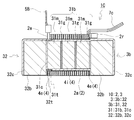
- FIG. 10 is a longitudinal sectional view of the coil element 2a of the reactor 1B (FIG. 6) cut in the vertical direction along the axial direction.
- the inner adhesive layer 4i is part of the coil circumferential direction in the cylindrical region between the turn forming portions of the coil elements 2a and 2b and the inner core portion 31, and the coil axis. It may be provided along a part of the direction.
- the coil 2 and the outer core portion 32 can be fixed by the end adhesive layer 4e, and the movement of the coil 2 can be further suppressed even if the region where the inner adhesive layer 4i is formed is part of the cylindrical region.
- the formation location of the inner adhesive layer 4i in the coil circumferential direction may be on the upper side or the lower side of the cylindrical region.
- the formation length in the coil circumferential direction of the inner adhesive layer 4i is preferably, for example, about 15% to 50% of the total circumferential length of the inner circumferential surface of the coil 2 (the outer circumferential surface of the inner core portion 31).
- the formation length of the inner adhesive layer 4i in the coil circumferential direction is such that when the inner peripheral surfaces of the coil elements 2a and 2b and the surface of the inner core portion 31 have a plane surface, the width of one plane (plane (Length along the coil circumferential direction) is preferred.
- the central portion of the coil 2 in the axial direction is preferable for the location of the inner adhesive layer 4i in the coil axial direction. If it does so, since the end surface and axial direction center of coil element 2a, 2b can be fixed with the magnetic core 3, the movement of the coil 2 is easy to be suppressed.
- the formation length of the inner adhesive layer 4i in the coil axial direction may be the length of the entire length in the coil axial direction, but the coil 2 and the outer core portion 32 can be fixed by the end adhesive layer 4e as described above. It may not be the length over the axial direction full length of coil element 2a, 2b.
- the axial region of the inner adhesive layer 4i may be 50% or more and 100% or less, particularly 50% or more and 80% or less of the length in the coil axial direction.
- the shape of the inner adhesive layer 4i is a piece.
- the inner adhesive layer 4i is formed in the coil circumferential direction only on the lower surface side of the coil elements 2a and 2b, and the axially formed position is substantially the center in the axial direction of the coil elements 2a and 2b.
- the circumferential region of the inner adhesive layer 4i covers the entire length of one plane of the inner circumferential surfaces of the coil elements 2a and 2b, and the axial region is about 30% of the axial length of the coil elements 2a and 2b. (FIG. 10).
- Reactor 1C applies the inner adhesive also to the lower surface of inner core portion 31 during the application of the end adhesive and the core adhesive in the manufacture of reactor 1B described above.
- the constituent members are combined as described above and the adhesive is cured, the lower surfaces of the coil elements 2a and 2b are pushed toward the inner core portion 31 side, and the inner peripheral surfaces of the coil elements 2a and 2b are moved to the inner core. Fully contact the inner adhesive on the lower surface of the part 31. In that state, the end adhesive, the core adhesive, and the inner adhesive are cured.
- the reactor 1C in which the coil elements 2a, 2b and the outer core portions 32 are fixed by the end adhesive layer 4e and the coil elements 2a, 2b and the inner core portion 31 are fixed by the inner adhesive layer 4i is obtained. .
- the reactor 1C in addition to fixing the end surfaces of the coil elements 2a, 2b and the outer core portion 32 by the end adhesive layer 4e, the inner peripheral surface and the inner core portion 31 of the coil elements 2a, 2b by the inner adhesive layer 4i. Can also be fixed. Therefore, the movement of the coil 2 can be further suppressed.
- Embodiment 4 In the fourth embodiment, with reference to FIG. 11, in addition to the end adhesive layer 4e described in the second embodiment, a mode including a fixed covering layer 4o that fixes the interval between the turns of the coil elements 2a and 2b will be described. . Since the reactor 1D of the fourth embodiment is the same as the second and third embodiments except that the reactor 1D includes the fixed coating layer 4o, the following description will be focused on differences from the second and third embodiments. . FIG. 11 shows an overall perspective view of the reactor 1D.
- the fixed coating layer 4o may be provided on a part of the outer circumferential surface of the coil elements 2a and 2b along at least a part of the axial direction of the coil elements 2a and 2b. If it does so, the space
- the formation location of the fixed coating layer 4o in the coil circumferential direction may be the upper side or the lower side of the combined body 10.
- the formation length of the fixed covering layer 4o along the circumferential direction of the coil is set such that the exposed area of the coil elements 2a and 2b is narrowed and the heat dissipation is not deteriorated so much. For example, 5% or more and 40% or less of the entire peripheral length of the outer peripheral surface of the coil 2 is preferable.
- the formation length of the fixed coating layer 4o along the coil circumferential direction is the width of one surface of the plane (the length along the coil circumferential direction in the plane). 30) or more. If it does so, it can have the outstanding heat dissipation, fixing turns.
- the formation location of the fixed coating layer 4o in the coil axial direction includes at least the center of the coil 2 in the axial direction.
- the length of the fixed coating layer 4o along the coil axis direction is, for example, preferably 50% or more of the length in the coil axis direction, more preferably 75% or more, and particularly preferably the total axial length.
- the thickness of the fixed coating layer 4o is preferably 0.5 mm or less, and particularly preferably 0.2 mm or less.
- the lower limit of the thickness of the fixed coating layer 4o is about 0.05 mm.
- the formation location in the coil circumferential direction of the fixed coating layer 4o is the upper surface, and the formation location in the coil axial direction is the total axial length. That is, the formation length of the fixed coating layer 4o in the coil axis direction extends over the entire length in the coil axis direction.
- the formation length of the fixed covering layer 4o in the coil circumferential direction is about 30% of the width of the upper surface (about 5% of the entire circumference of the coil).
- the thickness of the fixed coating layer 4o is 0.2 mm.
- the fixed covering layer 4o is preferably interposed at least partly between the turns of the coil elements 2a and 2b for the same reason as the inner adhesive layer 4i.
- the fixed coating layer 4o can be formed by curing the constituent material before curing of the fixed coating layer 4o after application or spraying, or after immersion in the constituent material. At this time, if the constituent material is interposed between the turns, the fixed coating layer 4o interposed between the turns can be obtained.
- an insulating resin (insulating varnish) used for insulating coating can be used as a constituent material of the fixed coating layer 4o.
- insulating resins such as polyamideimide resin, polyimide resin, polyesterimide resin, unsaturated polyester resin, alkyd resin, polyurethane resin, and epoxy resin.
- the reactor 1D covers the outer peripheral surface of the coil 2 with the above-described fixed coating layer 4o before combining the coil 2 and the magnetic core 3.
- the constituent material of the fixed covering layer 4o is applied to a predetermined portion of the outer peripheral surface of the coil elements 2a and 2b with a brush, and then the constituent material is cured.
- the coil elements 2a and 2b in which the interval between turns is fixed can be formed.
- the coil elements 2a and 2b are fixed to the outer core portion 32 by the end adhesive layer 4e in the same manner as the manufacture of the reactor 1B described above.
- the reactor 1D in which the turns of the coil elements 2a and 2b are fixed by the fixed coating layer 4o is obtained.
- the interval between the turns of the coil elements 2a and 2b can be fixed by the fixed coating layer 4o. . Therefore, the movement of the coil 2 can be further suppressed.
- the inner adhesive layer 4i (see FIGS. 1 to 4 and FIG. 10) described in the first and third embodiments may be provided.
- the formation part of the fixed coating layer 4o includes the side facing the inner adhesive layer with the inner core portion interposed therebetween. Since the turns can be fixed by the fixed coating layer 4o, and the coil and the inner core portion can be fixed by the inner adhesive layer, the movement of the coil can be easily suppressed.
- Embodiment 5 >>
- the form in which the thickness of the intervening region 32i of the side resin mold portion 32c is uniform over the entire region has been described. That is, the embodiment including the end adhesive layer 4e whose thickness increases along the inclined surface of the coil 2 has been described.
- a mode in which the thickness of the intervening region 32i increases along the inclined surface of the coil will be described mainly with reference to FIG. The following description will focus on differences from the second embodiment.
- FIG. 12 shows only the other outer core portion 32 (the left side in FIG. 6 and 7 in FIG. 6 and 7) for convenience of explanation, but one outer core portion 32 (see the right side in FIG. 6 and 7) has the same configuration. Prepare.
- the intervening region 32i of the side resin mold portion 32c is formed along the periphery of the inner core facing region (inner end surface 32e) of the side main body portion 32b, as shown by the hatched portion in FIG. 12, as in the second to fourth embodiments.
- This is an L-shaped region.
- region 32i the opposing surface with the coil element is comprised by the inclined surface corresponding to the form of the end surface of a coil element. That is, the surface constituting the intervening region 32i and the end surface of the coil element are parallel.
- the thickness of the intervening region 32i is increased along the inclination of the end surface of the coil element as the end surface of the coil element is separated from the intervening region 31i (coil facing region 32f).
- the thickness of the intervening region 32i gradually increases along the clockwise direction in FIG. That is, the thickness of the intervening region 32i (left side in FIG. 12) facing the coil element 2a (see FIG. 6) gradually increases from the upper side to the lower side of the outer core portion 32.
- the thickness of the intervening region 32i gradually increases from the center side (right side in FIG. 12) of the outer core portion 32 to the outer side in the width direction (left side in FIG. 12) on the lower side of the outer core portion 32.
- the thickness of the intervening region 32i (right side in FIG. 12) facing the coil element 2b (see FIG. 6) is the center of the outer core portion 32 from the outer side in the width direction (right side in FIG.
- the side resin mold portion 32c having the intervening region 32i can be formed by insert molding or the like.
- the thickness of the end adhesive layer can be made uniform over the entire region, it is easy to make the adhesive strength between the coil element and the outer core portion 32 uniform over the entire end adhesive layer. And the outer core portion 32 are easily fixed firmly.
- Embodiment 6 In the second embodiment, the form in which the shape of the end adhesive layer 4e is L-shaped has been described.
- the shape of the end adhesive layer may be U-shaped.
- the outer core portion includes a protruding portion that protrudes outward in the width direction of the side main body portion and faces the outer surface in the width direction of the coil end surface, or a side main body portion whose width is equal to or greater than the coil width.
- the overhanging part may be formed integrally with the side resin mold part by the constituent material of the side resin mold part.
- the U-shaped end adhesive layer can be interposed between the coil end surface and the outer core portion to fix the coil and the outer core portion, and the end portion can be compared with the L-shaped end adhesive layer. Since the adhesive region of the partial adhesive layer is wide, the movement of the coil can be further suppressed.
- Embodiment 7 >> In the seventh embodiment, with reference to FIGS. 13 and 14, a mode in which a heat radiating plate 9 is provided instead of the case 8 described in the first and second embodiments will be described. Since the reactors 1E and 1F of the seventh embodiment are the same as those of the first and second embodiments except that a reactor 9 is provided instead of the case 8, the following description will be focused on the differences. . 13 and 14 show perspective views of the reactors 1E and 1F as a whole, and the heat sink 9 is separated from the coil 2. FIG.
- the heat radiating plate 9 can enhance heat dissipation by being used for the heat radiating path of the coil 2.
- the heat radiating plate 9 can be disposed at any location of the coil 2 that generates heat during use.
- the heat sink 9 is disposed on the lower surface of the coil 2 and interposed between the coil 2 and the installation target.
- the heat sink 9 only needs to have a size corresponding to the lower surface of the coil 2, and the size and shape can be selected as appropriate.
- the heat radiating plate 9 is formed of a rectangular plate-like member having a size corresponding to the lower surface of the combined body 10 including not only the coil 2 but also the magnetic core 3.
- reactors 1E and 1F can transmit the heat of magnetic core 3 to the installation target.
- the heat sink 9 is sufficiently larger than the lower surface of the combined body 10, the heat sink 9 can be provided with a function as a base for integrally supporting the combined body 10, and it is expected that the reactor can be easily carried and handled.
- the heat radiating plate 9 is made larger than the lower surface of the combined body 10, for example, it does not interfere with the bolt 36 for fixing to the installation target and the boss 82 (see FIGS. 5 and 9) formed on the installation target.
- the thickness of the heat sink 9 can be selected as appropriate. For example, the thickness is about 2 mm or more and 5 mm or less.
- the constituent material of the heat sink 9 may be the same metal material as the case described above.
- the assembly 10 (coil 2) and the heat sink 9 can be fixed by an adhesive or an adhesive sheet (not shown). Although the movement of the coil 2 can be sufficiently suppressed by the inner adhesive layer 4i and the end adhesive layer 4e described above, the movement of the coil 2 (particularly, the bonding failure between the end 2e and the terminal fitting 5B) is further suppressed by this fixing. it can.
- Embodiment 8 The reactors according to the first to seventh embodiments have applications in which energization conditions are, for example, maximum current (direct current): about 100 A to 1000 A, average voltage: about 100 V to about 1000 V, and operating frequency: about 5 kHz to 100 kHz, typically electric It can be used for a component part of a converter mounted on a vehicle such as an automobile or a hybrid car, or a component part of a power conversion device including this converter.
- a vehicle 1200 such as a hybrid vehicle or an electric vehicle is driven by a main battery 1210, a power converter 1100 connected to the main battery 1210, and power supplied from the main battery 1210.
- Motor (load) 1220 is typically a three-phase AC motor, which drives the wheel 1250 when traveling and functions as a generator during regeneration.
- vehicle 1200 includes an engine in addition to motor 1220.
- an inlet is shown as a charging location of the vehicle 1200, but a form including a plug may be employed.
- the power conversion device 1100 includes a converter 1110 connected to the main battery 1210 and an inverter 1120 connected to the converter 1110 and performing mutual conversion between direct current and alternating current.
- the converter 1110 shown in this example boosts the DC voltage (input voltage) of the main battery 1210 of about 200V to 300V to about 400V to 700V when the vehicle 1200 is running, and supplies the inverter 1120 with power.
- converter 1110 steps down DC voltage (input voltage) output from motor 1220 via inverter 1120 to DC voltage suitable for main battery 1210 during regeneration, and causes main battery 1210 to be charged.
- the inverter 1120 converts the direct current boosted by the converter 1110 into a predetermined alternating current when the vehicle 1200 is running, and supplies the motor 1220 with electric power. During regeneration, the alternating current output from the motor 1220 is converted into direct current and output to the converter 1110. is doing.
- the converter 1110 includes a plurality of switching elements 1111, a drive circuit 1112 that controls the operation of the switching elements 1111, and a reactor L, and converts input voltage by ON / OFF repetition (switching operation). (In this case, step-up / down pressure) is performed.
- a power device such as a field effect transistor (FET) or an insulated gate bipolar transistor (IGBT) is used.
- the reactor L has the function of smoothing the change when the current is going to increase or decrease by the switching operation by utilizing the property of the coil that prevents the change of the current to flow through the circuit.
- the reactors of Embodiments 1 to 7 are provided.
- the converter 1110 includes the case 8 in which the liquid refrigerant C can be circulated and supplied, by storing the reactors 1A to 1F and the like in the case 8, a structure with excellent heat dissipation can be easily constructed.
- the power converter device 1100 and the converter 1110 can also expect improvement in heat dissipation.
- vehicle 1200 is connected to power supply device converter 1150 connected to main battery 1210, sub-battery 1230 serving as a power source for auxiliary devices 1240, and main battery 1210.
- Auxiliary power converter 1160 for converting to low voltage is provided.
- the converter 1110 typically performs DC-DC conversion, while the power supply device converter 1150 and the auxiliary power supply converter 1160 perform AC-DC conversion. Some power supply device converters 1150 perform DC-DC conversion.
- the reactors of the power supply device converter 1150 and the auxiliary power supply converter 1160 have the same configuration as the reactors of the first to seventh embodiments, and a reactor whose size and shape are appropriately changed can be used.
- the reactors of the first to seventh embodiments can be used for a converter that performs conversion of input power, and that only performs step-up or only performs step-down.
- the reactor of the present invention includes various converters such as an in-vehicle converter (typically a DC-DC converter) and an air conditioner converter mounted on a vehicle such as a hybrid vehicle, a plug-in hybrid vehicle, an electric vehicle, and a fuel cell vehicle. It can be suitably used as a component part of a power conversion device.
- an in-vehicle converter typically a DC-DC converter
- an air conditioner converter mounted on a vehicle
- a vehicle such as a hybrid vehicle, a plug-in hybrid vehicle, an electric vehicle, and a fuel cell vehicle. It can be suitably used as a component part of a power conversion device.
Landscapes
- Engineering & Computer Science (AREA)
- Power Engineering (AREA)
- Insulating Of Coils (AREA)
Abstract
放熱性を高めつつ、動作時の振動などに伴うコイルの動きを抑制できるリアクトルを提供する。巻線を巻回してなるコイルと、前記コイルの内側に配置される内側コア部、及び前記内側コア部に連結されて前記内側コア部と共に閉磁路を形成する外側コア部を有する磁性コアとを備えるリアクトルであって、前記外側コア部は、磁路となるサイド本体部を備え、前記サイド本体部は、前記内側コア部に対向する内側コア対向領域と、前記コイルの端面に対向するコイル対向領域とを含む対向面を有し、前記コイルの内周面における周方向の一部と前記内側コア部との間、及び前記コイルの端面と前記コイル対向領域との間の少なくとも一方の間に介在されて、前記内側コア部及び前記外側コア部の少なくとも一方と前記コイルとを固定する接着層とを備えるリアクトル。
Description
本発明は、ハイブリッド自動車などの車両に搭載される車載用DC-DCコンバータといった電力変換装置の構成部品に利用されるリアクトルに関するものである。特に、放熱性を高めつつ、動作時の振動などに伴うコイルの動きを抑制できるリアクトルに関する。
電圧の昇圧動作や降圧動作を行う回路の部品の一つに、リアクトルがある。リアクトルは、ハイブリッド自動車などの車両に搭載されるコンバータに利用される。そのリアクトルとして、例えば、特許文献1に示すものがある。
特許文献1のリアクトルは、コイル及び環状のコアの一部を内側樹脂部で一体に成形したコイル成形体と上記コアの残部との組立体が外側樹脂部で覆われて構成される。コイルは、銅製の平角線をエナメル被覆した被覆平角線を用いている。このリアクトルは、液体冷媒が流通される収納部に収納されて固定される。そして、収納部内に液体冷媒を流通させてリアクトルを浸漬状態とすることでリアクトルを冷却している。
特許文献1に記載されるリアクトルでは、コイルの全周がコアと一体の内側樹脂部及び外側樹脂部で覆われており、コイルと液体冷媒とが直接接触しない。そのため、リアクトルに対して、液体冷媒による放熱効果を更に高めることが望まれる。仮に、これら内側樹脂部及び外側樹脂部を省略すれば放熱性を高められるが、コイルとコアとが非固定状態となる。そうすると、リアクトル動作時のコイルやコアの振動、或いは外部環境からの影響などにより、コイルがコイル軸方向、径方向、及び周方向に動く。この動きに伴ってコイルとコアとが衝突したり擦れたり、コイルを形成する隣り合うターン同士が衝突したり擦れたりして騒音が増す。特に、コイルが被覆線で構成される場合には、コイルとコアとの衝突や擦れ、上記ターン同士の衝突や擦れによりコイルのエナメル被覆が損傷する虞がある。
本発明は、上記の事情に鑑みてなされたもので、その目的の一つは、放熱性を高めつつ、動作時の振動などに伴うコイルの動きを抑制できるリアクトルを提供することにある。
本発明の一形態に係るリアクトルは、巻線を巻回してなるコイルと、コイルの内側に配置される内側コア部、及び内側コア部に連結されて内側コア部と共に閉磁路を形成する外側コア部を有する磁性コアとを備える。外側コア部は、磁路となるサイド本体部を備える。サイド本体部は、内側コア部に対向する内側コア対向領域と、コイルの端面に対向するコイル対向領域とを含む対向面を有する。このリアクトルは、コイルの内周面における周方向の一部と内側コア部との間、及びコイルの端面とコイル対向領域との間の少なくとも一方の間に介在されて、内側コア部及び外側コア部の少なくとも一方とコイルとを固定する接着層を備える。
上記リアクトルは、放熱性を高めつつ、動作時の振動などに伴うコイルの動きを抑制できる。
《本発明の実施形態の説明》
最初に本発明の実施態様を列記して説明する。
最初に本発明の実施態様を列記して説明する。
(1)実施形態に係るリアクトルは、巻線を巻回してなるコイルと、コイルの内側に配置される内側コア部、及び内側コア部に連結されて内側コア部と共に閉磁路を形成する外側コア部を有する磁性コアとを備える。外側コア部は、磁路となるサイド本体部を備える。サイド本体部は、内側コア部に対向する内側コア対向領域と、コイルの端面に対向するコイル対向領域とを含む対向面を有する。このリアクトルは、コイルの内周面における周方向の一部と内側コア部との間、及びコイルの端面とコイル対向領域との間の少なくとも一方の間に介在されて、内側コア部及び外側コア部の少なくとも一方とコイルとを固定する接着層を備える。
上記の構成によれば、放熱性を高めつつ、動作時の振動などに伴うコイルの動きを抑制できる。詳しくは後述する。
(2)上記リアクトルの一形態として、接着層は、コイルの内周面における周方向の一部と内側コア部との間に介在されて、コイルと内側コア部とを固定する内側接着層を備えることが挙げられる。
上記の構成によれば、コイルと内側コア部との固定は、従来のようなコイルの全周を磁性コアと一体に覆う樹脂で行うのではなく、コイルの内周面と内側コア部との間に介在される内側接着層により行う。そのため、コイルの外周面を露出させることができ、リアクトルの放熱性を高めることができる。特に、このリアクトルを液体冷媒が流通される箇所に配置した場合に、液体冷媒とコイルとを直接接触させることができる。従って、コイルの放熱性、ひいてはリアクトルの放熱性をより効果的に高めることができる。
また、上記内側接着層でコイルと内側コア部とを固定することで、リアクトルの動作時のコイルや磁性コアの振動、或いは外部環境(例えば、上記液体冷媒など)からの影響に伴うコイルの軸方向、径方向、及び周方向への動きを抑制できる。そのため、コイルと磁性コアとの衝突や擦れ、コイルのターン同士の衝突や擦れを抑制できる。従って、それらの衝突や擦れに伴う騒音や、コイルの絶縁被覆の損傷を低減できる。
更に、内側接着層の形成箇所を、例えばコイルの周方向の一部でかつコイルの軸方向の少なくとも一部とすることで、詳しくは後述する実施形態で説明するが、内側コア部をコイル内に挿通させ易い。
(3)上記リアクトルの一形態として、内側接着層を備える場合、内側接着層は、コイルのうち巻線の端部側に設けられていることが挙げられる。
上記の構成によれば、巻線の端部への過剰な応力の付加を抑制し易い。コイルのターン形成部における巻線の端部側が軸方向、径方向、及び周方向へ動くと、巻線の端部はその動きに追随しようとする。通常、巻線の端部には、コイルに電力供給を行なう電源などの外部装置が接続される端子金具が接続される。そして、その端子金具は端子台などに固定されている。そのため、コイルが動くと、その動きによって巻線の端部と端子金具との接続箇所に過剰な応力が掛かる。上記の構成によれば、内側接着層がコイルのうち巻線の端部側に設けられていることで、ターン形成部の上記端部側の動きを抑制できて、巻線の端部のコイルの動きに伴う追随を抑制できる。
(4)上記リアクトルの一形態として、内側接着層を備える場合、内側接着層が接触するコイルの内周面及び内側コア部の表面は、平面で構成されていることが挙げられる。
上記の構成によれば、内側接着層が接触するコイル内周面及び内側コア部の表面が平面で構成されているため、内側接着層の厚みがその全域に亘って等しい内側接着層を形成し易い。そのため、内側接着層全域に亘ってコイルと内側コア部とを均等に固定し易く、コイルと内側コア部とをより強固に固定し易い。
(5)上記リアクトルの一形態として、内側接着層を備える場合、内側接着層が、コイルのターン間の少なくとも一部に介在されていることが挙げられる。
上記の構成によれば、コイルのターン同士の間隔を固定でき、ターン同士の衝突や擦れをより一層抑制できる。
(6)上記リアクトルの一形態として、接着層は、前記コイルの端面と前記コイル対向領域との間に介在され、前記コイルと前記外側コア部とを固定する端部接着層を備えることが挙げられる。
上記の構成によれば、コイルと外側コア部との固定は、従来のようなコイルの全周を磁性コアと一体に覆う樹脂で行うのではなく、コイルの端面と外側コア部との間に介在される端部接着層により行う。そのため、コイルの外周面を露出させることができ、リアクトルの放熱性を高めることができる。特に、このリアクトルを液体冷媒が流通される箇所に配置した場合に、液体冷媒とコイルとを直接接触させることができる。従って、コイルの放熱性、ひいてはリアクトルの放熱性をより効果的に高めることができる。
また、上記端部接着層でコイルと外側コア部とを固定することで、リアクトルの動作時のコイルやコアの振動、或いは外部環境(例えば、上記液体冷媒など)からの影響に伴うコイルの軸方向、径方向、及び周方向への動きを抑制できる。そのため、コイルと磁性コアとの衝突や擦れ、コイルのターン同士の衝突や擦れを抑制できる。従って、それらの衝突や擦れに伴う騒音や、コイルの絶縁被覆の損傷を低減できる。
更に、端部接着層の形成箇所を上記対向面の少なくとも一部とすることで、端部接着層の構成材料の塗布作業が簡易である。
(7)上記リアクトルの一形態として、外側コア部は、サイド本体部の外周の少なくとも一部を覆ってサイド本体部とコイルとの間を絶縁するサイド樹脂モールド部を備えることが挙げられる。端部接着層を備える場合、サイド樹脂モールド部は、サイド本体部と端部接着層との間に介在される介在領域を有する。
上記の構成によれば、上記介在領域を有するサイド樹脂モールド部を備えることで、サイド本体部とコイルとの間の絶縁を確保できる。また、サイド本体部を外部環境から保護できるため、物理的な衝撃によってサイド本体部が損傷し難い。更に、このリアクトルを液体冷媒が流通される箇所に配置した場合に、液体冷媒に対する防錆性を向上できる。
(8)上記リアクトルの一形態として、サイド樹脂モールド部が介在領域を有する場合、介在領域におけるコイルとの対向面は、コイルの端面の形態に対応した傾斜面で構成されることが挙げられる。このとき、介在領域の厚さは、コイルの端面がコイル対向領域から離れるにしたがってコイルの端面の傾斜に沿って厚くしている。
上記の構成によれば、端部接着層の厚さをその全域に亘って均一にできる。そのため、コイルと外側コア部との接着強度を端部接着層全域に亘って均一にし易く、コイルと外側コア部とを強固に固定し易い。
(9)上記リアクトルの一形態として、コイルの外周面における周方向の一部に、コイルの軸方向の少なくとも一部に沿って形成されてコイルのターン同士の間隔を固定する固定被覆層を備えることが挙げられる。
上記の構成によれば、コイルの外周面の露出面積を多くしつつコイルのターン同士の間隔を固定でき、ターン同士の衝突や擦れをより一層抑制できる。
(10)上記リアクトルの一形態として、接着層が、紫外線硬化型接着剤で構成されていることが挙げられる。
上記の構成によれば、紫外線硬化型接着剤は紫外線を照射して硬化させるため、接着層の形成の際、熱硬化性の接着剤に比べて高温に加熱する必要がない。また、紫外線硬化型接着剤は紫外線を照射しないと硬化しないので、接着層の形成の際、例えば、硬化までの時間などに制約が少ない。更に、硬化速度は比較的速いため、接着層の形成時間、ひいてはリアクトルの製造時間を短くし易い。
(11)上記リアクトルの一形態として、内側コア部は、磁路となるミドル本体部と、ミドル本体部の外周の少なくとも一部を覆ってミドル本体部とコイルとの間を絶縁するミドル樹脂モールド部とを備えることが挙げられる。
上記の構成によれば、ミドル樹脂モールド部を備えることで、ミドル本体部とコイルとの間の絶縁を確保できる。また、ミドル本体部を外部環境から保護できるため、物理的な衝撃によってミドル本体部が損傷し難い。更に、このリアクトルを液体冷媒が流通される箇所に配置した場合に、液体冷媒に対する防錆性を向上できる。
(12)上記リアクトルの一形態として、外側コア部は、サイド本体部に加えて、端子金具と、サイド樹脂モールド部とを備えることが挙げられる。端子金具は、コイルの巻線の端部に接続される。サイド樹脂モールド部は、サイド本体部の外周の少なくとも一部を覆ってサイド本体部とコイルとの間、及びサイド本体部と端子金具との間を絶縁すると共に、サイド本体部と端子金具とを一体に保持する。
上記の構成によれば、サイド樹脂モールド部を備えることで、サイド本体部とコイルとの間、及びサイド本体部と端子金具との間の絶縁を確保できる。また、サイド本体部を外部環境から保護できるため、物理的な衝撃によってサイド本体部が損傷し難い。更に、このリアクトルを液体冷媒が流通される箇所に配置した場合に、液体冷媒に対する防錆性を向上できる。そして、サイド本体部と端子金具とを一体物として取り扱えるため、部品点数を低減でき、リアクトルの組立作業性を向上できる。
(13)上記リアクトルの一形態として、コイルと磁性コアとの組合体を内部に収納すると共に、液体冷媒が供給及び排出されるケースを備えることが挙げられる。
上記の構成によれば、コイルの全周が従来のように樹脂で覆われておらず、コイルを液体冷媒に直接接触させて冷却できるため、リアクトルの放熱性を向上できる。特に、ケースは液体冷媒が供給及び排出されることで、組合体を冷却する液体冷媒の流れを制御でき、組合体を効果的に冷却できる
また、上述の接着層によりコイルとコアとが固定されているため、液体冷媒がコイルにかかっても、コイルの軸方向、径方向、及び周方向への動きや変形を抑制できる。そのため、コイルとコアとの衝突や擦れ、コイルのターン同士の衝突や擦れを抑制でき、騒音を低減できる。コイルが被覆線で構成されている場合には、被覆線の被覆の損傷を抑制することもできる。
《本発明の実施形態の詳細》
本発明の実施形態の詳細を、以下に図面を参照しつつ説明する。
本発明の実施形態の詳細を、以下に図面を参照しつつ説明する。
《実施形態1》
〔リアクトルの全体構成〕
図1~5を参照して、実施形態1のリアクトル1Aを説明する。リアクトル1Aは、詳しくは後述するリアクトル1Aの使用状態で説明するが、例えば、液体冷媒に直接曝される箇所に配置されて使用される。リアクトル1Aは、コイル2と、コイル2の内外に配置されて閉磁路を形成する磁性コア3との組合体10を備える。リアクトル1Aの主たる特徴とするところは、コイル2と、磁性コア3のうちコイル2に対向する特定箇所との間に配置されてコイル2と磁性コア3とを固定する接着層4を備える点にある。以下、リアクトル1Aの特徴部分及び関連する部分の構成、並びに主要な効果を順に説明し、その後、各構成を詳細に説明する。ここでは、組合体10の設置対象側を設置側(下側)、その反対側を対向側(上側)とする。図中の同一符号は同一名称物を示す。
〔リアクトルの全体構成〕
図1~5を参照して、実施形態1のリアクトル1Aを説明する。リアクトル1Aは、詳しくは後述するリアクトル1Aの使用状態で説明するが、例えば、液体冷媒に直接曝される箇所に配置されて使用される。リアクトル1Aは、コイル2と、コイル2の内外に配置されて閉磁路を形成する磁性コア3との組合体10を備える。リアクトル1Aの主たる特徴とするところは、コイル2と、磁性コア3のうちコイル2に対向する特定箇所との間に配置されてコイル2と磁性コア3とを固定する接着層4を備える点にある。以下、リアクトル1Aの特徴部分及び関連する部分の構成、並びに主要な効果を順に説明し、その後、各構成を詳細に説明する。ここでは、組合体10の設置対象側を設置側(下側)、その反対側を対向側(上側)とする。図中の同一符号は同一名称物を示す。
〔主たる特徴部分及び関連する部分の構成〕
[組合体]
(コイル)
コイル2は、図1、4に示すように、接合部の無い1本の連続する巻線2wを螺旋状に巻回してなる一対のコイル素子2a、2bと、両コイル素子2a、2bを連結する連結部2rとを備える。巻線2wには平角線からなる導体の外周に絶縁被覆を被覆した被覆平角線を用い、コイル素子2a、2bは、被覆平角線をエッジワイズ巻きにしたエッジワイズコイルで構成している。コイル素子2a、2bの配置は、各軸方向が平行するように並列(横並び)した状態としている。コイル素子2a、2bの形状は、互いに同一の巻数の中空の筒状体(四角筒)であり、コイル素子2a、2bの端面形状は、矩形枠の角部を丸めた形状である。即ち、コイル素子2a、2bの内周面は、四つの平面と、隣り合う平面同士を連結する四つの曲面とで構成されている。連結部2rは、コイル2の一端側(図1、4紙面右側)において巻線の一部をU字状に屈曲して構成している。
[組合体]
(コイル)
コイル2は、図1、4に示すように、接合部の無い1本の連続する巻線2wを螺旋状に巻回してなる一対のコイル素子2a、2bと、両コイル素子2a、2bを連結する連結部2rとを備える。巻線2wには平角線からなる導体の外周に絶縁被覆を被覆した被覆平角線を用い、コイル素子2a、2bは、被覆平角線をエッジワイズ巻きにしたエッジワイズコイルで構成している。コイル素子2a、2bの配置は、各軸方向が平行するように並列(横並び)した状態としている。コイル素子2a、2bの形状は、互いに同一の巻数の中空の筒状体(四角筒)であり、コイル素子2a、2bの端面形状は、矩形枠の角部を丸めた形状である。即ち、コイル素子2a、2bの内周面は、四つの平面と、隣り合う平面同士を連結する四つの曲面とで構成されている。連結部2rは、コイル2の一端側(図1、4紙面右側)において巻線の一部をU字状に屈曲して構成している。
コイル素子2a、2bの巻線2wの両端部2eは、連結部2r側と反対側でフラットワイズ曲げされてターン形成部から引き延ばされている。ターン形成部から巻線2wの端部2eに至る引き出し部は、コイル周方向の上方側(図2の上側)に位置しており、両端部2eの引き出し方向はコイル素子2a、2bの軸方向の一端側である。両端部2eには、導電部材(ここでは後述の端子金具5A)が接続される。
(磁性コア)
磁性コア3は、図4に示すように、コイル素子2a、2bの内側に配置される一対の内側コア部31と、コイル2が配置されず、コイル2から突出(露出)されている一対の外側コア部32、320とを備える。磁性コア3は、離間して配置される内側コア部31を挟むように外側コア部32、320が配置され、内側コア部31の端面と外側コア部320の内端面32eとを接触させて環状に形成される。これら内側コア部31、31及び外側コア部32、320により、コイル2を励磁したとき、閉磁路を形成する。内側コア部31、31と外側コア部32、320との具体的な連結・分離形態については後述する。
磁性コア3は、図4に示すように、コイル素子2a、2bの内側に配置される一対の内側コア部31と、コイル2が配置されず、コイル2から突出(露出)されている一対の外側コア部32、320とを備える。磁性コア3は、離間して配置される内側コア部31を挟むように外側コア部32、320が配置され、内側コア部31の端面と外側コア部320の内端面32eとを接触させて環状に形成される。これら内側コア部31、31及び外側コア部32、320により、コイル2を励磁したとき、閉磁路を形成する。内側コア部31、31と外側コア部32、320との具体的な連結・分離形態については後述する。
〈内側コア部〉
内側コア部31の形状は、コイル2の形状(コイル2の内部空間)に合わせた形状とすることが好ましい。ここでは、図4に示すように、内側コア部31の形状は直方体状であり、その角部(コイル素子2a、2bの上記曲面に対向する領域)は、コイル素子2a、2bの上記曲面に沿って丸めている。即ち、内側コア部31の端面形状は、角部を丸めた矩形状であり、内側コア部31の側面(コイル素子2a、2bの周方向に沿った面)は、四つの平面と、隣り合う平面同士を連結する四つの曲面とで構成されている(図3、4)。
内側コア部31の形状は、コイル2の形状(コイル2の内部空間)に合わせた形状とすることが好ましい。ここでは、図4に示すように、内側コア部31の形状は直方体状であり、その角部(コイル素子2a、2bの上記曲面に対向する領域)は、コイル素子2a、2bの上記曲面に沿って丸めている。即ち、内側コア部31の端面形状は、角部を丸めた矩形状であり、内側コア部31の側面(コイル素子2a、2bの周方向に沿った面)は、四つの平面と、隣り合う平面同士を連結する四つの曲面とで構成されている(図3、4)。
[接着層]
接着層4は、コイル2と内側コア部31とを固定する内側接着層、及びコイル2と外側コア部32とを固定する端部接着層の少なくとも一方を備える。内側接着層は、コイル2と内側コア部31との間の特定箇所に配置され、端部接着層は、コイル2と外側コア部32との間に配置される。ここでは、接着層4が内側接着層4iで構成される形態を説明する。接着層4が端部接着層4eで構成される形態は実施形態2(図6~図9)で説明し、接着層4が内側接着層4iと外側接着層4eとで構成される形態は実施形態3(図10)、その他の形態は実施形態4以降で順次説明する。
接着層4は、コイル2と内側コア部31とを固定する内側接着層、及びコイル2と外側コア部32とを固定する端部接着層の少なくとも一方を備える。内側接着層は、コイル2と内側コア部31との間の特定箇所に配置され、端部接着層は、コイル2と外側コア部32との間に配置される。ここでは、接着層4が内側接着層4iで構成される形態を説明する。接着層4が端部接着層4eで構成される形態は実施形態2(図6~図9)で説明し、接着層4が内側接着層4iと外側接着層4eとで構成される形態は実施形態3(図10)、その他の形態は実施形態4以降で順次説明する。
内側接着層4iは、コイル2と内側コア部31とを固定する。内側接着層4iは、コイル素子2a、2bの内周面と内側コア部31の表面との間において、コイル素子2a、2bの周方向の一部で、かつコイル素子2a、2bの軸方向の少なくとも一部に沿って設けられる。内側接着層4iの形状は、コイル素子2a、2bと内側コア部31との接着領域の範囲に応じて片状、テープ状、シート状など種々の形状をとり得る。
内側接着層4iの形成箇所は、コイル2の軸方向、径方向、及び周方向の両方における巻線2wの端部2e側、即ち、コイル2のターン形成部と内側コア部31との間の筒状領域のうち、少なくとも巻線2wの端部2eに近接する側が好ましい。例えば、巻線2wのうちターン形成部から巻線2wの端部2eに至る引き出し部がコイル軸方向の一端側にある場合、上記筒状領域の少なくとも一端側に内側接着層4iを形成する。この引き出し部が内側コア部31の上部側にある場合、上記筒状領域のうち少なくとも内側コア部31の上側に内側接着層4iを形成すればよい。これは、ターン形成部の振動が巻線2wの端部2eと端子金具5Aとの接合状態に悪影響を及ぼすことを抑制できるからである。
コイル2のうち端部2eは端子金具5Aに固定されるが、内側接着層4iを備えない場合、ターン形成部は磁性コア3に対して固定されない。コイル2や磁性コア3が振動すると、端部2eは動かないが、ターン形成部はコイル2の軸方向、径方向、及び周方向に動く。このターン形成部の動きは、ターン形成部から巻線2wの端部2eに至る引き出し部に応力を生じさせ、その応力の発生は巻線2wの端部2eと端子金具5Aとの接合不良の一因となる虞がある。よって、内側接着層4iの形成箇所を上記筒状領域のうち、少なくとも巻線2wの端部2eに近接する側とすることで、ターン形成部の振動の影響が巻線2wの引き出し部に及ぶことを抑制し、上記接合不良の発生を可及的に低減できる。
コイル周方向における内側接着層4iの形成長は、コイル2の内周面(内側コア部31の外周面)の全周長の15%以上50%以下程度が好ましい。この全周長の15%以上であれば、コイル2の振動を適切に抑制でき、全周長の50%以下であれば内側コア部31をコイル2内に挿入する際、内側接着層4iが邪魔になり難い。
コイル軸方向における内側接着層4iの形成長は、コイル2の全長の25%以上、更に50%以上、75%以上、特に全長とすることが好ましい。コイル2の全長の25%以上であれば、巻線2wの端部2eと端子金具5Aとの接合不良を抑制し易い。コイル2の全長に亘って内側接着層4iを形成すれば、コイル2の振動や移動をより確実に抑制でき、全ターン間の擦れも抑制し易い。
内側接着層4iの厚さは、コイル素子2a、2bと内側コア部31とを固定しつつ、コイル素子2a、2bと内側コア部31との間隔を所望の間隔にできる程度が挙げられる。所望の間隔とは、例えば、内側接着層4iによりコイル素子2a、2bと内側コア部31とが十分な絶縁を確保できる程度が挙げられる。特に、内側接着層4iを介してコイル素子2a、2bと内側コア部31とを固定させた際に、コイル素子2a、2bの内周面と内側コア部31の表面との間隔が周方向全周に亘って均等になるようにすることが好ましい。具体的には、内側接着層4iの厚さは、0.05mm以上0.5mm以下が挙げられる。
本実施形態では、内側接着層4iの形状は矩形のシート状である。内側接着層4iの形成箇所は、コイル2(内側コア部31)の周方向では上面側のみとし、その軸方向では全長に亘る領域としている(図2、3)。特に、コイル周方向の内側接着層4iの形成箇所は、各コイル素子2a,2bの内周面のうち一つの平面としている。巻線2wの引き出し部は、コイル軸方向の一端側(図2の左側)で、かつコイル周方向の上方側(図2の上側)に位置している。そのため、本実施形態の内側接着層4iの形成箇所であれば、コイル2をその内周面の上方側で、かつ一端側のみならず、軸方向の全長に亘って内側コア部31を固定できる。特に、内側接着層4iを内側コア部31の上面側のみに設けると、コイル2と内側コア部31との組立時、コイル2を上部から内側コア部31に向けて押すことで、内側コア部31の上面にコイル2の内周面を押圧させ易い。
内側接着層4iは、各コイル素子2a、2bのターン間の少なくとも一部に介在させることが好ましい。そうすれば、コイル素子2a、2bの各ターンの隣接する面を固定してターンの間隔を固定でき、ターン同士の衝突や擦れをより一層抑制できる。このような内側接着層4iは、例えば、内側コア部31の上面に接着剤を塗布し、コイル2を上部から内側コア部31に向けて押すことで接着剤をコイル素子2a、2bのターン間に浸入させ、その状態で接着剤を硬化(固化)することで形成できる。
内側接着層4iの形成は、接着剤をコイル素子2a、2bの外側からその外周面(上面)に垂らしてコイル素子2a、2bのターン間からコイル素子2a、2bと内側コア部31との間へ流動させた後、接着剤を硬化することでも行える。この場合、接着剤には、粘度の低い(例えば、1Pa・s程度)液状の接着剤を用いることができる。そうすれば、接着剤を各コイル素子2a、2bの内側(内側コア部31との間)に流動させ易い。また、ターン間を通って各コイル素子2a、2bと内側コア部31との間に流動した接着剤をその間に介在させた状態を維持し易い。
内側接着層4iの構成材料は、絶縁性及び耐熱性を有することが好ましい。この耐熱性とは、リアクトル1Aの使用時における最高到達温度に対して軟化しないことを言う。そうすれば、リアクトル1Aの動作時にコイル2と内側コア部31とを確実に固定できる。
内側接着層4iの構成材料は、例えば、エポキシ樹脂、シリコーン樹脂、不飽和ポリエステルなどの熱硬化性の絶縁性接着剤、ポリフェニレンスルフィド(PPS)樹脂、液晶ポリマー(LCP)などの熱可塑性の絶縁性接着剤、ウレタンアクリレート、アクリル樹脂アクリレート、エポキシアクリレートなどの紫外線(光)硬化型の絶縁性接着剤などを好適に利用できる。特に、紫外線硬化型の絶縁性接着剤が好適である。紫外線を照射すれば接着剤を硬化でき、内側接着層4iの形成の際に熱硬化性の接着剤に比べて高温まで加熱する必要がないからである。紫外線を照射しないと接着剤は硬化しないので、内側接着層4iの形成の際、例えば、硬化までの時間などに制約が少ない。接着剤の硬化速度は比較的速いため、内側接着層4iの形成時間、ひいてはリアクトル1Aの製造時間を短くし易い。
その他、内側接着層4iの構成材料には、熱融着型の樹脂を利用することもできる。熱融着型の樹脂とは、加熱により溶融又は軟化して融着性を示す状態を経て硬化する熱融着材料を構成材料とするものである。熱融着型の樹脂としては、例えば、エポキシ樹脂、ポリイミド樹脂などが挙げられる。例えば、熱融着型の樹脂のシート材を用いる場合、未硬化の状態でコイル2と内側コア部31との間にシート材を配置した後、そのシート材を加熱することで溶融してコイル2及び内側コア部31に融着する。その際、シート材が溶融により変形してコイル2のターン間の段差や隙間、内側コア部31の外周面の凹凸などに入り込み、コイル2の内周面や内側コア部31の外周面に密着する。その状態で硬化することでコイル2及び内側コア部31に密着した状態となる。シート材は密着状態となるため、放熱効果も期待できる。熱融着型の樹脂の溶融・硬化に必要な加熱温度及び保持時間は、構成材料に応じて適宜選択すればよく、例えば、加熱温度は80℃以上160℃以下程度が挙げられる。
〔リアクトルの主たる特徴部分における作用効果〕
リアクトル1Aによれば、コイル素子2a、2bの内周面と内側コア部31の表面との間に、コイル素子2a、2bの周方向の一部で、コイル素子2a、2bの軸方向全長に亘って内側接着層4iを備えることで、コイル2と磁性コア3とを固定できる。そのため、従来のようなコイル2の表面全域を覆う樹脂を備える必要がないので、液体冷媒Cとコイル2とを直接接触させることができ、リアクトル1Aの放熱性を高められる。また、液体冷媒Cなどの外部環境からの影響や、アクトル1Aの動作時のコイル2や磁性コア3の振動などに伴うコイル2の軸方向、径方向、及び周方向への動きを抑制できる。そのため、コイル2と磁性コア3との衝突や擦れ、コイル2のターン同士の衝突や擦れを抑制でき、騒音の低減、及びコイル2の絶縁被覆の損傷を低減できる。
リアクトル1Aによれば、コイル素子2a、2bの内周面と内側コア部31の表面との間に、コイル素子2a、2bの周方向の一部で、コイル素子2a、2bの軸方向全長に亘って内側接着層4iを備えることで、コイル2と磁性コア3とを固定できる。そのため、従来のようなコイル2の表面全域を覆う樹脂を備える必要がないので、液体冷媒Cとコイル2とを直接接触させることができ、リアクトル1Aの放熱性を高められる。また、液体冷媒Cなどの外部環境からの影響や、アクトル1Aの動作時のコイル2や磁性コア3の振動などに伴うコイル2の軸方向、径方向、及び周方向への動きを抑制できる。そのため、コイル2と磁性コア3との衝突や擦れ、コイル2のターン同士の衝突や擦れを抑制でき、騒音の低減、及びコイル2の絶縁被覆の損傷を低減できる。
〔その他の特徴部分を含む各構成の説明〕
[コイル]
巻線2wの導体の構成材料は、銅、アルミニウム、その合金といった導電性材料が挙げられ、絶縁被覆の構成材料は、エナメル(代表的にはポリアミドイミド)などの絶縁性材料が挙げられる。導体の形状は、丸線などでもよい。コイル素子2a、2bの端面形状は、円形状など適宜変更できる。コイルは、独立した2つの巻線をそれぞれ螺旋状に巻回してなる一対のコイル素子と、両コイル素子とは独立した部材で、両コイル素子を連結する連結部材とを備える構成としてもよい。
[コイル]
巻線2wの導体の構成材料は、銅、アルミニウム、その合金といった導電性材料が挙げられ、絶縁被覆の構成材料は、エナメル(代表的にはポリアミドイミド)などの絶縁性材料が挙げられる。導体の形状は、丸線などでもよい。コイル素子2a、2bの端面形状は、円形状など適宜変更できる。コイルは、独立した2つの巻線をそれぞれ螺旋状に巻回してなる一対のコイル素子と、両コイル素子とは独立した部材で、両コイル素子を連結する連結部材とを備える構成としてもよい。
[磁性コア]
磁性コア3は、上述したように一対の内側コア部31と一対の外側コア部32、320とを備える。ここでは、磁性コア3の形態は、一方の外側コア部32(図4の紙面右側)及び両内側コア部31を一体化したU字型のコア成形体3bと、他方の外側コア部320(図4の紙面左側)とを備える形態としている。U字型のコア成形体3bと他方の外側コア部320とは、接着剤を介して接合できる。外側コア部32、320と内側コア部31の上面は略面一である。一方、外側コア部32、320の下面は、内側コア部31の下面よりも突出してコイル2の下面と略面一になるように外側コア部32、320の大きさを調整している。組合体10の下面は、主として、二つの外側コア部32、320の下面と、コイル2の下面とで構成される。
磁性コア3は、上述したように一対の内側コア部31と一対の外側コア部32、320とを備える。ここでは、磁性コア3の形態は、一方の外側コア部32(図4の紙面右側)及び両内側コア部31を一体化したU字型のコア成形体3bと、他方の外側コア部320(図4の紙面左側)とを備える形態としている。U字型のコア成形体3bと他方の外側コア部320とは、接着剤を介して接合できる。外側コア部32、320と内側コア部31の上面は略面一である。一方、外側コア部32、320の下面は、内側コア部31の下面よりも突出してコイル2の下面と略面一になるように外側コア部32、320の大きさを調整している。組合体10の下面は、主として、二つの外側コア部32、320の下面と、コイル2の下面とで構成される。
(コア成形体)
U字型のコア成形体3bは、磁路となる一方のサイド本体部32b及び磁路となる一対のミドル本体部31bを有するコア部品と、このコア部品を覆って両本体部31b、32bを一体化すると共にコア部品とコイル2とを絶縁する連結樹脂モールド部とを備える。具体的には、連結樹脂モールド部は、ミドル本体部31bの少なくとも一部を覆うミドル樹脂モールド部31cと、サイド本体部32bの少なくとも一部を覆うサイド樹脂モールド部32cとを備える。内側コア部31は、ミドル本体部31bとミドル樹脂モールド部31cとを備え、外側コア部32は、サイド本体部32bとサイド樹脂モールド部32cとを備える。ここでは、ミドル樹脂モールド部31cとサイド樹脂モールド部32cとは、同一の構成材料で一連(一体)に形成されている。
U字型のコア成形体3bは、磁路となる一方のサイド本体部32b及び磁路となる一対のミドル本体部31bを有するコア部品と、このコア部品を覆って両本体部31b、32bを一体化すると共にコア部品とコイル2とを絶縁する連結樹脂モールド部とを備える。具体的には、連結樹脂モールド部は、ミドル本体部31bの少なくとも一部を覆うミドル樹脂モールド部31cと、サイド本体部32bの少なくとも一部を覆うサイド樹脂モールド部32cとを備える。内側コア部31は、ミドル本体部31bとミドル樹脂モールド部31cとを備え、外側コア部32は、サイド本体部32bとサイド樹脂モールド部32cとを備える。ここでは、ミドル樹脂モールド部31cとサイド樹脂モールド部32cとは、同一の構成材料で一連(一体)に形成されている。
〈コア部品〉
{ミドル本体部}
ミドル本体部31bは、軟磁性材料を主成分とする複数のコア片31mと、コア片31mよりも比透磁率が小さい材料からなるギャップ材31gとが交互に積層配置された積層体である(図4)。コア片31mとギャップ材31gとの一体化には、特に接着剤を利用すると扱い易い。その上、コア片31mが磁歪によって振動する材質で構成され、ギャップ材31gがアルミナのような剛性の高い材質で構成された場合でも、コア片31mとギャップ材31gとの接触・非接触に伴う騒音を低減できると期待される。その他、コア片31mとギャップ材31gとの一体化に接着テープなどを利用することもできる。ここでは、コア片31mとギャップ材31gとを接着剤によって一体化している。ミドル本体部31b(磁性コア3)は、ギャップ材31gを備えていない形態やエアギャップを備える形態とすることができる。
{ミドル本体部}
ミドル本体部31bは、軟磁性材料を主成分とする複数のコア片31mと、コア片31mよりも比透磁率が小さい材料からなるギャップ材31gとが交互に積層配置された積層体である(図4)。コア片31mとギャップ材31gとの一体化には、特に接着剤を利用すると扱い易い。その上、コア片31mが磁歪によって振動する材質で構成され、ギャップ材31gがアルミナのような剛性の高い材質で構成された場合でも、コア片31mとギャップ材31gとの接触・非接触に伴う騒音を低減できると期待される。その他、コア片31mとギャップ材31gとの一体化に接着テープなどを利用することもできる。ここでは、コア片31mとギャップ材31gとを接着剤によって一体化している。ミドル本体部31b(磁性コア3)は、ギャップ材31gを備えていない形態やエアギャップを備える形態とすることができる。
{サイド本体部}
一方のサイド本体部32bは、ミドル本体部31bと同様、軟磁性材料を主成分とするコア片である。サイド本体部32bの形状は、適宜選択できる。ここでは、上面・下面がドーム状(内端面32eから外方に向かって断面積が小さくなる変形台形状)の柱状体としている。サイド本体部32bの形状として、例えば、角柱状体とすることもできる。
一方のサイド本体部32bは、ミドル本体部31bと同様、軟磁性材料を主成分とするコア片である。サイド本体部32bの形状は、適宜選択できる。ここでは、上面・下面がドーム状(内端面32eから外方に向かって断面積が小さくなる変形台形状)の柱状体としている。サイド本体部32bの形状として、例えば、角柱状体とすることもできる。
一対のミドル本体部31bと一方のサイド本体部32bとは、接着剤によって接合できる。一対のミドル本体部31bと一方のサイド本体部32bとは、接着剤により接合せず、連結樹脂モールド部により一体に覆うことで接合することもできる。
〈連結樹脂モールド部〉
{ミドル樹脂モールド部}
ミドル樹脂モールド部31cは、ミドル本体部31bとコイル素子2a、2bとの間を絶縁する。ミドル樹脂モールド部31cの被覆領域は、少なくともミドル本体部31bにおけるコイル素子2a、2bの周方向に沿った面(上下面及び両側面)の一部とすることが挙げられる。ミドル樹脂モールド部31cの被覆領域が広いほど、コイル素子2a、2bとの絶縁を確保し易い上に、例えば組合体10を液体冷媒Cに接触する箇所に配置する場合、ミドル本体部31bの防錆性を向上できる。
{ミドル樹脂モールド部}
ミドル樹脂モールド部31cは、ミドル本体部31bとコイル素子2a、2bとの間を絶縁する。ミドル樹脂モールド部31cの被覆領域は、少なくともミドル本体部31bにおけるコイル素子2a、2bの周方向に沿った面(上下面及び両側面)の一部とすることが挙げられる。ミドル樹脂モールド部31cの被覆領域が広いほど、コイル素子2a、2bとの絶縁を確保し易い上に、例えば組合体10を液体冷媒Cに接触する箇所に配置する場合、ミドル本体部31bの防錆性を向上できる。
ミドル樹脂モールド部31cの被覆領域には、ミドル本体部31bにおける外側コア部320側との対向面が含まれていても含まれていなくてもよい。ミドル樹脂モールド部31cの構成材料は一般に非磁性材料であるため、上記対向面を覆う場合、ギャップ材として機能する。ミドル樹脂モールド部31cで上記対向面を覆う(覆わず露出させる)場合、外側コア部320のサイド本体部32の内端面32eをサイド樹脂モールド部32cから露出させる(サイド樹脂モールド部32cで覆って露出させない)ことが挙げられる。ミドル本体部31bの上記対向面及び他方のサイド本体部32bの内端面32eのいずれか一方のみを樹脂で被覆して両者を接着剤により固定すれば、樹脂成形に伴う寸法誤差を接着剤厚さで調整できてギャップ長を精度よく調整し易い。
ここでは、ミドル樹脂モールド部31cの被覆領域は、ミドル本体部31bにおける一方のサイド本体部32bとの接続箇所を除く全面としている。即ち、ミドル本体部31bの上記対向面もミドル樹脂モールド部31cにより覆われ、外側コア部320との接続箇所である内側コア部31の端面はミドル樹脂モールド部31cの構成材料により構成されている。
{サイド樹脂モールド部}
一方のサイド樹脂モールド部32cは、サイド本体部32bとコイル素子2a、2bとの間を絶縁する。サイド樹脂モールド部32cの被覆領域は、少なくとも内端面32eのコイル素子2a、2bとの対向箇所とすることが挙げられる。一方のサイド樹脂モールド部32cの被覆領域は、サイド本体部32bの上面の連結部2rとの対向箇所を含むことが好ましい。サイド樹脂モールド部32cの被覆領域は、広いほどサイド本体部32bを保護できる上に、例えば組合体10を液体冷媒Cに接触する箇所に配置する場合、サイド本体部32bの防錆性を向上できる。サイド本体部32bはコイル2から突出(露出)されており、サイド本体部32bが圧粉成形体で構成されていて、サイド樹脂モールド部32cにより被覆されていれば、絶縁性及び防錆性に加えて、軟磁性粉末の脱落防止にも効果的である。ここでは、サイド樹脂モールド部32cの被覆領域は、サイド本体部32bにおける一対のミドル本体部31bとの接触箇所を除く全領域としている。即ち、コア成形体3bは、その全面が連結樹脂モールド部により覆われている。
一方のサイド樹脂モールド部32cは、サイド本体部32bとコイル素子2a、2bとの間を絶縁する。サイド樹脂モールド部32cの被覆領域は、少なくとも内端面32eのコイル素子2a、2bとの対向箇所とすることが挙げられる。一方のサイド樹脂モールド部32cの被覆領域は、サイド本体部32bの上面の連結部2rとの対向箇所を含むことが好ましい。サイド樹脂モールド部32cの被覆領域は、広いほどサイド本体部32bを保護できる上に、例えば組合体10を液体冷媒Cに接触する箇所に配置する場合、サイド本体部32bの防錆性を向上できる。サイド本体部32bはコイル2から突出(露出)されており、サイド本体部32bが圧粉成形体で構成されていて、サイド樹脂モールド部32cにより被覆されていれば、絶縁性及び防錆性に加えて、軟磁性粉末の脱落防止にも効果的である。ここでは、サイド樹脂モールド部32cの被覆領域は、サイド本体部32bにおける一対のミドル本体部31bとの接触箇所を除く全領域としている。即ち、コア成形体3bは、その全面が連結樹脂モールド部により覆われている。
樹脂モールド部31c、32cの厚さは、0.1mm以上3mm以下が挙げられる。樹脂モールド部31c、32cの厚さを0.1mm以上とすることで、コイル素子2a、2bに対する絶縁性を向上できる上に、液体冷媒Cによる磁性コア3の錆を防止できる。一方、樹脂モールド部31c、32cの厚さを3mm以下とすることで、樹脂モールド部31c、32cが厚くなり過ぎない。
(他方の外側コア部)
他方の外側コア部320(図4紙面左)は、上述の一方の外側コア部32と同様のサイド本体部32bとサイド樹脂モールド部32cとを備える。他方のサイド樹脂モールド部32cの被覆領域は、少なくともサイド本体部32bにおけるコイル素子2a、2bとの対向箇所とすることが挙げられる。ここでは、後述するようにサイド樹脂モールド部32cにより端子金具5Aとサイド本体部32bとが一体に保持されるため、他方のサイド樹脂モールド部32cの被覆領域として、更に端子金具5Aとの対向箇所を含むことが好ましい。他方のサイド樹脂モールド部32cの被覆領域は、上述の一方の外側コア部32と同様の理由から広いほど好ましい。ここでは、他方のサイド本体部32bにおける内側コア部31の端面との対向領域のみ露出させ、それ以外の箇所を覆っている。
他方の外側コア部320(図4紙面左)は、上述の一方の外側コア部32と同様のサイド本体部32bとサイド樹脂モールド部32cとを備える。他方のサイド樹脂モールド部32cの被覆領域は、少なくともサイド本体部32bにおけるコイル素子2a、2bとの対向箇所とすることが挙げられる。ここでは、後述するようにサイド樹脂モールド部32cにより端子金具5Aとサイド本体部32bとが一体に保持されるため、他方のサイド樹脂モールド部32cの被覆領域として、更に端子金具5Aとの対向箇所を含むことが好ましい。他方のサイド樹脂モールド部32cの被覆領域は、上述の一方の外側コア部32と同様の理由から広いほど好ましい。ここでは、他方のサイド本体部32bにおける内側コア部31の端面との対向領域のみ露出させ、それ以外の箇所を覆っている。
〈各本体部、ギャップ材、及び各樹脂モールド部の構成材料〉
ミドル本体部31b・サイド本体部32bを構成する各コア片の主成分である軟磁性材料には、鉄や鉄合金、フェライトといった非金属などが挙げられる。コア片は、上記軟磁性材料からなる軟磁性粉末を用いた成形体や、絶縁被膜を有する磁性薄板(例えば、ケイ素鋼板に代表される電磁鋼板)を複数積層した積層体を利用できる。上記成形体は、圧粉成形体(圧粉磁心)の他、焼結体、軟磁性粉末と樹脂とを含む複合材料などが挙げられる。複合材料は、射出成形などを利用することで、複雑な立体形状であっても、容易に成形できる。複合材料中のバインダとなる樹脂は、エポキシ樹脂などの熱硬化性樹脂やPPS樹脂などの熱可塑性樹脂を利用できる。上記複合材料中の軟磁性粉末の含有量は、複合材料を100体積%とするとき、20体積%以上75体積%以下が挙げられる。残部は、樹脂やアルミナやシリカなどのセラミックスといった非金属有機材料、非金属無機材料などの非磁性材料である。ここでは、各コア片はいずれも圧粉成形体としている。
ミドル本体部31b・サイド本体部32bを構成する各コア片の主成分である軟磁性材料には、鉄や鉄合金、フェライトといった非金属などが挙げられる。コア片は、上記軟磁性材料からなる軟磁性粉末を用いた成形体や、絶縁被膜を有する磁性薄板(例えば、ケイ素鋼板に代表される電磁鋼板)を複数積層した積層体を利用できる。上記成形体は、圧粉成形体(圧粉磁心)の他、焼結体、軟磁性粉末と樹脂とを含む複合材料などが挙げられる。複合材料は、射出成形などを利用することで、複雑な立体形状であっても、容易に成形できる。複合材料中のバインダとなる樹脂は、エポキシ樹脂などの熱硬化性樹脂やPPS樹脂などの熱可塑性樹脂を利用できる。上記複合材料中の軟磁性粉末の含有量は、複合材料を100体積%とするとき、20体積%以上75体積%以下が挙げられる。残部は、樹脂やアルミナやシリカなどのセラミックスといった非金属有機材料、非金属無機材料などの非磁性材料である。ここでは、各コア片はいずれも圧粉成形体としている。
ギャップ材31gの具体的な材料は、アルミナや不飽和ポリエステルなどの非磁性材料、PPS樹脂などの非磁性材料と磁性材料(磁性材料の例は、鉄粉などの軟磁性粉末)とを含む混合物などが挙げられる。
樹脂モールド部31c、32cの構成材料は、絶縁性に優れる材料が好ましく、絶縁性に加えて防錆性や熱伝導性に優れる材料が特に好ましい。このような材料としては、例えば、PPS樹脂などが挙げられる。樹脂モールド部31c、32cの形成は、インサート成形や構成樹脂への浸漬などで行える。
各コア片を上述の複合材料で構成した場合、樹脂モールド部で各本体部を被覆しない構成とすることもできる。即ち、内側コア部及び外側コア部はそれぞれ、複合材料からなるミドル本体部及びサイド本体部で構成される。複合材料の表面は樹脂から軟磁性粉末が殆ど露出しない状態となる。そのため、コイル素子2a、2bとの間を絶縁できる上に、複合材料に含まれる軟磁性粉末の腐食を抑制できる。勿論、上記各本体部を上述の樹脂モールド部で被覆してもよいが、その場合、樹脂モールド部の構成材料には、樹脂モールド部の形成時に複合材料の樹脂が軟化や損傷しないような材料を選択することが挙げられる。
磁性コア3は、一方の外側コア部32(320)及び一方の内側コア部31を一体化したL字型のコア成形体を一対備える形態とすることもできる。この場合、各L字型のコア成形体は、上記一方のサイド本体部32b及び上記一方のミドル本体部31bと、両本体部32b、31bを一体に保持する連結樹脂モールド部とを備える。更に、磁性コア3は、各々独立した部材で構成される一対の内側コア部31、及び一対の外側コア部32、320を備える形態とすることもできる。この場合、各内側コア部31は、上記ミドル本体部31bと上記ミドル樹脂モールド部31cとを備え、各外側コア部32、320は、上記サイド本体部32bとサイド樹脂モールド部32cとを備える。L字型のコア成形体同士や、内側コア部31と外側コア部32、320とは、接着剤で接合できる。
[磁性コアのその他の構成]
(取付部)
両サイド樹脂モールド部32cは、組合体10を設置対象に固定する取付部33を備えることが好ましい(図1、図4)。取付部33は、サイド樹脂モールド部32cの構成材料によりサイド樹脂モールド部32cと一体に形成することが挙げられる。取付部33は、サイド本体部32bにおけるコイル素子2a、2bの並列方向に張り出すフランジ状に設けられている。取付部33の形成箇所は、リアクトル1Aの設置対象の固定箇所(後述するケース8のボス82)の高さに合わせて適宜選択することが挙げられる。ここでは、外側コア部32、320の高さ方向における略中間位置に設けている。
(取付部)
両サイド樹脂モールド部32cは、組合体10を設置対象に固定する取付部33を備えることが好ましい(図1、図4)。取付部33は、サイド樹脂モールド部32cの構成材料によりサイド樹脂モールド部32cと一体に形成することが挙げられる。取付部33は、サイド本体部32bにおけるコイル素子2a、2bの並列方向に張り出すフランジ状に設けられている。取付部33の形成箇所は、リアクトル1Aの設置対象の固定箇所(後述するケース8のボス82)の高さに合わせて適宜選択することが挙げられる。ここでは、外側コア部32、320の高さ方向における略中間位置に設けている。
取付部33には、組合体10を設置対象に固定する際に用いられるボルト36(図5)を貫通させて、ボルト36による締付力を受けるカラー35が埋設されている。カラー35の材質は、金属などの剛性材が挙げられる。そうすれば、取付部33を構成するサイド樹脂モールド部32cの損傷を抑制でき、組合体10をボス82に強固に固定できる。
(仕切部)
両サイド樹脂モールド部32cは、コイル素子2a、2b同士の絶縁を確保する仕切部34を備えることが好ましい(図4)。仕切部34は、コイル素子2a、2b間に介在するように設けられる。仕切部34は、サイド樹脂モールド部32cの構成材料によりサイド樹脂モールド部32cと一体に形成することが挙げられる。
両サイド樹脂モールド部32cは、コイル素子2a、2b同士の絶縁を確保する仕切部34を備えることが好ましい(図4)。仕切部34は、コイル素子2a、2b間に介在するように設けられる。仕切部34は、サイド樹脂モールド部32cの構成材料によりサイド樹脂モールド部32cと一体に形成することが挙げられる。
(端子金具)
他方の外側コア部320は、電源などの外部装置(図示略)からコイル2への電力供給を行う端子金具5Aを備える。端子金具5Aは、平板状の金属片を屈曲させた略L字状の金具である。端子金具5Aは、各コイル素子2a、2bの端部2eに接続される細板状のコイル側接続片51と、上記外部装置につながるリードを接続する太板状のリード側接続片52と、両片51,52を連結する太板状の中間片とを備える。この中間片は、サイド樹脂モールド部32cに埋設されることが好ましい。そうすれば、中間片をサイド樹脂モールド部32cによりサイド本体部32bと共に一体に保持でき、端子金具5Aとサイド本体部32bとを一体に取り扱えることができるため、部品点数を低減できてリアクトル1Aの組立作業性を向上できる。コイル側接続片51と端部2eとの接続は、例えば、ヒュージング(熱カシメ)、TIG(Tungsten Inert Gas)溶接などの溶接、はんだ付け、ろう付け、カシメなど種々の手段により行える。
他方の外側コア部320は、電源などの外部装置(図示略)からコイル2への電力供給を行う端子金具5Aを備える。端子金具5Aは、平板状の金属片を屈曲させた略L字状の金具である。端子金具5Aは、各コイル素子2a、2bの端部2eに接続される細板状のコイル側接続片51と、上記外部装置につながるリードを接続する太板状のリード側接続片52と、両片51,52を連結する太板状の中間片とを備える。この中間片は、サイド樹脂モールド部32cに埋設されることが好ましい。そうすれば、中間片をサイド樹脂モールド部32cによりサイド本体部32bと共に一体に保持でき、端子金具5Aとサイド本体部32bとを一体に取り扱えることができるため、部品点数を低減できてリアクトル1Aの組立作業性を向上できる。コイル側接続片51と端部2eとの接続は、例えば、ヒュージング(熱カシメ)、TIG(Tungsten Inert Gas)溶接などの溶接、はんだ付け、ろう付け、カシメなど種々の手段により行える。
コイル側接続片51における端部2eとの接続面は、端部2eにおけるコイル側接続片51との接続面よりも広いことが好ましい。そうすれば、端部2eとコイル接続片51との接続を行い易い。内側接着層4iを形成する際、上述のようにコイル素子2a、2bの外周面を内側コア部31側に押圧することがある。端子金具5Aがサイド樹脂モールド部32cによりサイド本体部32bと一体に保持されていれば、端部2eがコイル側接続片51に対して位置ずれする虞がある。しかし、コイル側接続片51の上記接続面が端部2eの上記接続面よりも広ければ、たとえコイル素子2a、2bの上記押圧により端部2eの位置が多少ずれても両者の接触領域を確保し易い。
一方、リード側接続片52には、貫通孔52hが設けられている。貫通孔52hは、上記リード線を端子金具5Aに接続するボルトといった連結部材(図示略)が嵌め込まれる。リアクトル1Aが後述するケース8を備える場合、リード側接続片52はケース8の外側へ引き出される。
端子金具5Aはサイド樹脂モールド部32cによりサイド本体部32bと一体に保持されているが、サイド樹脂モールド部32cで一体に保持することなく、別途端子台などでサイド樹脂モールド部32cに接続させることもできる。その場合、端子台とサイド樹脂モールド部32cとが互いに係合する係合部を備えることが挙げられる。
なお、本例では、コイル2への電力供給を行う導電部材として板状の端子金具5Aを備える形態を示しているが、その他、導体線とすることができる。導体線は、銅や銅合金、アルミニウムやアルミニウム合金といった導電性に優れる金属によって構成された単一の線材、又は複数の線材を撚り合わせた撚線、又は撚線を圧縮成形した圧縮線などが挙げられる。この導体線は、絶縁被覆を有していない裸線でもよいし、絶縁被覆を備える被覆線でもよい。
(その他)
両ミドル樹脂モールド部31cは、コイル素子2a、2bと内側コア部31との間隔を保持する突条部(図示略)を備えることもできる。突条部は、コイル素子2a、2bの軸方向の少なくとも一部に沿って形成する。突条部は、ミドル樹脂モールド部31cの構成材料によりミドル樹脂モールド部31cと一体に形成することが挙げられる。
両ミドル樹脂モールド部31cは、コイル素子2a、2bと内側コア部31との間隔を保持する突条部(図示略)を備えることもできる。突条部は、コイル素子2a、2bの軸方向の少なくとも一部に沿って形成する。突条部は、ミドル樹脂モールド部31cの構成材料によりミドル樹脂モールド部31cと一体に形成することが挙げられる。
突条部の形成箇所は、内側コア部31の外周面上であれば適宜選択できるが、ミドル樹脂モールド部31cにおける内側接着層4iに接する面(上面)や、それ以外の面(下面と側面)が挙げられる。上面側に設ける場合、二本の突条部を離隔して設けることが好ましい。そうすれば、内側接着層4iを形成する際、突条部間を接着剤の形成箇所に利用できる。接着剤を硬化して内側接着層4iを形成する際に、上述のようにコイル素子2a、2bを内側コア部31側に押圧して接着剤が圧接されても、突条部が壁となって他の面(側面)に接着剤が流れ難い。そのため、形成された内側接着層4iをその全域に亘って均一な厚さにし易い。上面以外の面に設ける場合、突条部は、上記下面に二本、更には両側面にそれぞれ一本ずつ設けることが挙げられる。そうすれば、内側コア部31のコイル周方向全周に亘ってコイル素子2a,2bとの間隔を保持し易い。
突条部のコイル軸方向に沿った長さは、長いほど内側コア部31と各コイル素子2a、2bとをコイル2の軸方向に沿って間隔を均一に保ちやすい。そのため、突条部の上記長さは、コイル軸方向全長に亘る長さが好ましい。
他方の外側コア部320は、リード側接続片52同士の間に介在して両片52の間隔を保つ突条の間隔保持部37(図1)を備えることが好ましい。そうすれば、リード側接続片52同士の絶縁性を高められる。間隔保持部37は、サイド樹脂モールド部32cの構成材料によりサイド樹脂モールド部32cと一体に形成することが挙げられる。
リアクトル1Aは、内側接着層4iによりコイル素子2a、2bと内側コア部31とを強固に固定する押付片(図示略)を備えることもできる。押付片は、上記筒状領域に挿通されて、上記筒状領域における押付片と対向する側で内側コア部31をコイル2側へ押し付ける。押付片は、サイド樹脂モールド部32cの構成材料によりサイド樹脂モールド部32cと一体に形成してもよいし、サイド樹脂モールド部32cとは別部材で構成してもよい。前者の場合、押付片は、上記筒状領域のうちミドル本体部31bを挟んで内側接着層4iと対向する箇所に介在するように、外側コア部320の内端面32eに突設することが挙げられる。押付片の形状は、例えば、矩形状などが挙げられる。押付片は、コイル2と内側コア部31との間に挿入させ易いように、押付片の先端側の厚さが徐々に薄くなるテーパー形状としてもよい。押付片を備えれば、押付片を内側コア部31とコイル素子2a、2bとの間に挿通した際、内側コア部31の上面とコイル2の内周面とを近づけられる。そのため、内側接着層4iを形成する際、コイル2及び内側コア部31と接着剤とを十分に接触させた状態で接着剤を硬化して内側接着層4iを形成でき、コイル素子2a、2bと内側コア部31とを強固に固定し易い。押付片は、突条部を備える場合、突条部と干渉しないように設けることが挙げられる。
〔リアクトルの使用状態〕
リアクトル1Aの使用状態を、図5を参照して説明する。
リアクトル1Aの使用状態を、図5を参照して説明する。
[ケース]
リアクトル1Aは、組合体10を収納・固定するケース8を備えることもできる(図5)。ケース8は、その内部に液体冷媒Cが供給・排出される箱状の部材で、液体冷媒Cをケース8内へ供給する供給口80iと、ケース8内の液体冷媒Cをケース8外へ排出する排出口80oとを備える。コイル2の全周が従来のように樹脂で覆われておらず、コイル2を液体冷媒Cに直接接触させて冷却できるため、リアクトル1Aの放熱性を向上できる。供給口80iからケース8内に供給されて排出口80oからケース8外へ排出された液体冷媒Cは、冷却器(図示略)などにより所定の温度に冷却されて、再び供給口80iからケース8内へ供給される。こうして液体冷媒Cがケース8内へ循環供給される。ケース8は液体冷媒Cが供給及び排出されることで、組合体10を冷却する液体冷媒Cの流れを制御でき、組合体10を効果的に冷却できる。また、内側接着層4iによりコイル2と磁性コア3とが固定されているため、液体冷媒Cがコイル2に掛かっても、コイル2の軸方向、径方向、及び周方向への動きや変形を抑制できる。そのため、コイル2と磁性コア3との衝突や擦れ、コイル2のターン同士の衝突や擦れを抑制でき、騒音を低減できる。コイル2が被覆線で構成されている場合には、被覆線の被覆の損傷を抑制することもできる。
リアクトル1Aは、組合体10を収納・固定するケース8を備えることもできる(図5)。ケース8は、その内部に液体冷媒Cが供給・排出される箱状の部材で、液体冷媒Cをケース8内へ供給する供給口80iと、ケース8内の液体冷媒Cをケース8外へ排出する排出口80oとを備える。コイル2の全周が従来のように樹脂で覆われておらず、コイル2を液体冷媒Cに直接接触させて冷却できるため、リアクトル1Aの放熱性を向上できる。供給口80iからケース8内に供給されて排出口80oからケース8外へ排出された液体冷媒Cは、冷却器(図示略)などにより所定の温度に冷却されて、再び供給口80iからケース8内へ供給される。こうして液体冷媒Cがケース8内へ循環供給される。ケース8は液体冷媒Cが供給及び排出されることで、組合体10を冷却する液体冷媒Cの流れを制御でき、組合体10を効果的に冷却できる。また、内側接着層4iによりコイル2と磁性コア3とが固定されているため、液体冷媒Cがコイル2に掛かっても、コイル2の軸方向、径方向、及び周方向への動きや変形を抑制できる。そのため、コイル2と磁性コア3との衝突や擦れ、コイル2のターン同士の衝突や擦れを抑制でき、騒音を低減できる。コイル2が被覆線で構成されている場合には、被覆線の被覆の損傷を抑制することもできる。
供給口80iは、組合体10の上方に設けられ、排出口80oは、後述のボス82の高さと略同様の位置に設けられている。排出口80oの口径φoは供給口80iの口径φiよりも小さくしている。そうして、図5に示すようにコイル2の上面が液体冷媒Cの液面下に位置するように、組合体10が液体冷媒Cに常時浸漬されるようにしている。
ケース8は、組合体10の設置側面に対向する取付面81と、取付面81から突設され、組合体10をケース8内に固定するボス82とを備えることが好ましい。そうすれば、ケース8の取付面81全体の厚さを厚くすることなくボス82に締め付けるボルト36の締付長を確保でき、組合体10をボス82に強固に固定し易い。取付面81の薄肉化により、ケース8を軽量化できる。ボス82の形状は、円柱状としているが角柱状など適宜変更できる。
ボス82の数は、取付部33の数と同数とすることができ、ボス82の配置箇所は、取付部33に対応する箇所とすることが挙げられる。ボス82の取付部33との接触面には、取付部33を固定するボルト36が挿通される挿通穴が形成されている。挿通穴には、雌ねじ加工が施されており、この挿通穴にボルト36をねじ止めして取付部33(組合体10)をケース8に固定できる。
ケース8の材質は、アルミニウムやその合金、マグネシウムやその合金、銅やその合金、銀やその合金、鉄やオーステナイト系ステンレス鋼などの金属が挙げられる。特に、アルミニウムやマグネシウム、これらの合金は、軽量である上に、シールド機能を期待できる。アルミニウムやその合金は放熱性及び耐食性にも優れ、マグネシウムやその合金は制振性に優れるため、車載部品に好適に利用できる。その他、ケース8の材質は、ポリブチレンテレフタレート(PBT)樹脂、ウレタン樹脂、PPS樹脂、アクリロニトリル-ブタジエン-スチレン(ABS)樹脂などの絶縁性樹脂が挙げられる。絶縁性樹脂には、窒化珪素、アルミナ、窒化アルミニウム、窒化ほう素、及び炭化珪素から選択される少なくとも1種のセラミックスフィラーが含有されていても良い。
[液体冷媒]
液体冷媒Cは、リアクトル1Aの使用時の最高到達温度によって形態が変化しないもの(気化しないもの)が好適に利用できる。具体的には、オートマチックトランスミッションの潤滑油であるATF(Automatic Transmission Fluid)、フロリナート(登録商標)などのフッ素系不活性液体、HCFC-123やHFC-134aなどのフロン系冷媒、メタノールやアルコールなどのアルコール系冷媒、アセトンなどのケトン系冷媒などが挙げられる。リアクトル1Aが自動車用途である場合などでは、ATFを流用すると、液体冷媒Cを別途用意しなくてよく、ATFの循環供給機構を利用すれば、液体冷媒Cを利用するリアクトル1Aにおける放熱構造を簡単に形成できる。
液体冷媒Cは、リアクトル1Aの使用時の最高到達温度によって形態が変化しないもの(気化しないもの)が好適に利用できる。具体的には、オートマチックトランスミッションの潤滑油であるATF(Automatic Transmission Fluid)、フロリナート(登録商標)などのフッ素系不活性液体、HCFC-123やHFC-134aなどのフロン系冷媒、メタノールやアルコールなどのアルコール系冷媒、アセトンなどのケトン系冷媒などが挙げられる。リアクトル1Aが自動車用途である場合などでは、ATFを流用すると、液体冷媒Cを別途用意しなくてよく、ATFの循環供給機構を利用すれば、液体冷媒Cを利用するリアクトル1Aにおける放熱構造を簡単に形成できる。
[センサ]
リアクトル1Aは、リアクトル1Aの動作時の物理量(例えば、温度、電流値、電圧値、加速度など)を測定するセンサ7sを備えることができる(図3、4)。センサ7sによる測定結果に基づいてリアクトル1Aの動作を安定化させることができる。センサ7sは、サーミスタといった感熱素子を備える温度センサであり、感熱素子を保護する保護部(例えば、樹脂などのチューブ)と、感熱素子からの情報を外部に伝える配線7cとを備える。センサ7sの配置箇所は、例えば、コイル素子2a、2b同士の間における下側及び上側のうち、コイル素子2a、2bの角部で囲まれる領域が挙げられる。
リアクトル1Aは、リアクトル1Aの動作時の物理量(例えば、温度、電流値、電圧値、加速度など)を測定するセンサ7sを備えることができる(図3、4)。センサ7sによる測定結果に基づいてリアクトル1Aの動作を安定化させることができる。センサ7sは、サーミスタといった感熱素子を備える温度センサであり、感熱素子を保護する保護部(例えば、樹脂などのチューブ)と、感熱素子からの情報を外部に伝える配線7cとを備える。センサ7sの配置箇所は、例えば、コイル素子2a、2b同士の間における下側及び上側のうち、コイル素子2a、2bの角部で囲まれる領域が挙げられる。
センサ7sの組合体10への組み付けは、例えば、図4に示すようなホルダ70を用いることができる。ホルダ70は、コイル素子2a、2b間で両仕切部34間に介在して支持される本体部71と、本体部71の両端において、仕切部34に係合するフック72fとを備える。ホルダ70をコイル素子2a、2b間に差し込んだ際、フック72fが仕切部34の下端と係合されると共に、本体部71が両仕切部34に支持される。それにより、ホルダ70の位置が実質的にずれないのでこの位置を良好に維持できる。このホルダ70によりセンサ7sの一部が覆われる構成としている。そうすれば、センサ7sは、例えば、液体冷媒Cに接触し難く、リアクトル1Aの物理量を適切に測定し易い。ホルダ70の構成材料は、上述の樹脂モールド部の構成材料と同様の絶縁性樹脂とすることができる。そうすれば、ホルダ70がコイル素子2a、2bに接触しても、両者の絶縁性に優れる。ホルダ70を用いずにセンサ7sをエポキシ系接着剤、アクリル系接着剤などの接着剤のみで所定位置に固定する形態とすることもできる。
〔リアクトルの製造〕
リアクトル1Aは、代表的には、コイル2と磁性コア3の準備⇒接着剤の塗布⇒組合体10の組立⇒接着剤を硬化して内側接着層4iの形成という工程により製造できる。
リアクトル1Aは、代表的には、コイル2と磁性コア3の準備⇒接着剤の塗布⇒組合体10の組立⇒接着剤を硬化して内側接着層4iの形成という工程により製造できる。
上述したコイル2と、上述のコア成形体3b及び他方の外側コア部320を備える磁性コア3とを準備する。続いて、各コイル素子2a、2bの内周面、及びコア成形体3bの内側コア部31の上面の少なくとも一方に内側接着層4iを構成する内側接着剤を塗布する。ここでは、内側コア部31の上面に内側接着剤を塗布した。次に、内側コア部31を各コイル素子2a、2b内に挿入し、他方の外側コア部320の内端面32eと内側コア部31の端面とをコア接着剤で固定してコイル2と磁性コア3とを組み合わせる。そして、コイル素子2a、2bの上面を内側コア部31側へ押し寄せて、コイル素子2a、2bの内周面を内側コア部31の上面の内側接着剤と十分に接触させる。その状態で、内側コア部31の上面の内側接着剤を硬化させて、コイル素子2a、2bと内側コア部31とを固定する。以上により、コイル素子2a、2bと内側コア部31との間に介在された内側接着層4iによりコイル素子2a、2bと内側コア部31とを固定したリアクトル1Aが得られる。
リアクトル1Aがケース8を備える場合には、組合体10をケース8に収納・固定する。ケース8のボス82の挿通穴に、取付部33のカラー35の挿通孔が合うように取付面81に組合体10を配置する。そして、カラー35にボルト36を挿通させると共に、上記挿通穴にねじ止めする。そうして組合体10をボス82に固定する。その状態で、ケース8の供給口80iからケース8内に液体冷媒Cを供給し、排出口80oからケース8外に液体冷媒Cを排出することでケース8内に液体冷媒Cを循環供給して、リアクトル1Aを冷却する。
《実施形態2》
〔リアクトルの全体構成〕
実施形態1では、接着層4をコイル2と内側コア部31とを固定する内側接着層4iで構成する形態を説明した。実施形態2では、図6~図9を参照して、接着層4をコイル2と外側コア部32とを固定する端部接着層4eで構成する形態を説明する。実施形態2のリアクトル1Bは、実施形態1のリアクトル1Aと同様、例えば、液体冷媒に直接曝される箇所に配置されて使用される(図9)。以下の説明は、実施形態1との相違点を中心に行う。
〔リアクトルの全体構成〕
実施形態1では、接着層4をコイル2と内側コア部31とを固定する内側接着層4iで構成する形態を説明した。実施形態2では、図6~図9を参照して、接着層4をコイル2と外側コア部32とを固定する端部接着層4eで構成する形態を説明する。実施形態2のリアクトル1Bは、実施形態1のリアクトル1Aと同様、例えば、液体冷媒に直接曝される箇所に配置されて使用される(図9)。以下の説明は、実施形態1との相違点を中心に行う。
(コイル)
コイル2のコイル素子2a、2bの並列方向に沿った長さは、外側コア部32の同方向に沿った長さよりも長い(図8)。コイル素子2a、2bの端面は、巻線2wの巻回ピッチに応じて、コイル素子2a、2bの軸方向に対して傾斜する傾斜面である。コイル素子2a、2bの端面における外側コア部32との対向領域(外側コア対向領域2f)は、外側コア部32のサイズ(幅や高さ)によって適宜選択できる。ここでは、外側コア対向領域2fは、図7、8の斜線部に示すL字状の領域で、コイル端面全面のうち、コイル素子2a、2bの隣り合う側の内側端面と、下側の下側端面と、両端面を連結する曲端面とで構成されている。
コイル2のコイル素子2a、2bの並列方向に沿った長さは、外側コア部32の同方向に沿った長さよりも長い(図8)。コイル素子2a、2bの端面は、巻線2wの巻回ピッチに応じて、コイル素子2a、2bの軸方向に対して傾斜する傾斜面である。コイル素子2a、2bの端面における外側コア部32との対向領域(外側コア対向領域2f)は、外側コア部32のサイズ(幅や高さ)によって適宜選択できる。ここでは、外側コア対向領域2fは、図7、8の斜線部に示すL字状の領域で、コイル端面全面のうち、コイル素子2a、2bの隣り合う側の内側端面と、下側の下側端面と、両端面を連結する曲端面とで構成されている。
端部2eの引き出し箇所は、連結部2r側と反対側で、コイル周方向の上方側(図6,7の上側)に位置している。両端部2eには、電源などの外部装置(図示略)からコイル2への電力供給を行う導電部材(ここでは端子金具5B)が接続される。リアクトル1Bが後述するケース8を備える場合、端子金具5Bはケース8の外側へ引き出される(図9)。
〈外側コア部〉
外側コア部32は、図7,8に示すように、内側コア部31に対向する内側コア対向領域(内端面32e)、及びコイル素子2a、2b(外側コア対向領域2f)に対向するコイル対向領域32f(同図斜線部)を含む対向面を有する。この対向面は、外側コア部32の上面(下面)に直交する平面で構成されている。即ち、コイル対向領域32fを構成する面は、上述の外側コア対向領域2fを構成する面と非平行である。ここでは、コイル対向領域32fは、図7,8に斜線部に示すように、上述したコイル素子2a、2bの外側コア対向領域2fと同様のL字状の領域で、上記対向面のうち内端面32eの周縁(内端面32e及び仕切部34(後述)の間と内端面32eの下側)に沿って形成されている。
外側コア部32は、図7,8に示すように、内側コア部31に対向する内側コア対向領域(内端面32e)、及びコイル素子2a、2b(外側コア対向領域2f)に対向するコイル対向領域32f(同図斜線部)を含む対向面を有する。この対向面は、外側コア部32の上面(下面)に直交する平面で構成されている。即ち、コイル対向領域32fを構成する面は、上述の外側コア対向領域2fを構成する面と非平行である。ここでは、コイル対向領域32fは、図7,8に斜線部に示すように、上述したコイル素子2a、2bの外側コア対向領域2fと同様のL字状の領域で、上記対向面のうち内端面32eの周縁(内端面32e及び仕切部34(後述)の間と内端面32eの下側)に沿って形成されている。
[端部接着層]
端部接着層4eは、コイル2と外側コア部32とを固定する。端部接着層4eの形成箇所は、各コイル素子2a,2bの少なくとも一端における外側コア対向領域2fと外側コア部32のコイル対向領域32fとの間のコア‐コイル対向領域が挙げられる。
端部接着層4eは、コイル2と外側コア部32とを固定する。端部接着層4eの形成箇所は、各コイル素子2a,2bの少なくとも一端における外側コア対向領域2fと外側コア部32のコイル対向領域32fとの間のコア‐コイル対向領域が挙げられる。
コイル2のうち端部2eは端子金具5Bに固定されるが、端部接着層4eを備えない場合、ターン形成部は磁性コア3に対して固定されないためターン形成部が動き、上述したように巻線2wの端部2eと端子金具5Bとの接合不良の一因となる虞がある。よって、端部接着層4eの形成箇所を上記コア‐コイル対向領域の少なくとも一方とすることで、ターン形成部の振動の影響が巻線2wの引き出し部に及ぶことを抑制し、上記接合不良の発生を可及的に低減できる。
端部接着層4eの形成箇所を連結部側の上記コア‐コイル対向領域とすれば、コイル素子2a、2bの動きを抑制し易い。その上、上述の端部接着層4eを備えない場合に比べて、上記接合不良を抑制し易い。一方、端部接着層4eの形成箇所を、端部2e側の上記コア‐コイル対向領域とすれば、コイル素子2a、2bの動きを抑制し易い。その上、端部接着層4eの形成箇所を連結部側のコア‐コイル対向領域とする場合に比べて、上記接合不良を抑制し易い。特に、端部接着層4eの形成箇所は、端部2e側及び連結部側の両方のコア‐コイル対向領域とすることが好ましい。ここでは、コイル軸方向端部側及び連結部側の両方のコア‐コイル対向領域に端部接着層4eを設けている。
端部接着層4eの形成領域は、上記コア‐コイル対向領域の少なくとも一部が挙げられる。例えば、端部接着層4eの形成領域は、上記コア‐コイル対向領域のうち巻線2wの端部2eに近い側が好ましい。そうすれば、コイル素子2a、2bにおける端部2eの上記接合箇所近傍の動きを抑制し易く、上記接合不良を抑制し易い。端部接着層4eの形成領域は、端部2eに近い側から上記コア‐コイル対向領域の全長の50%以上に亘ることが好ましく、更には75%以上、特に全長に亘ることが好ましい。
端部接着層4eの厚さは、コイル素子2a、2bと外側コア部32とを固定でき、かつ端部接着層4eによりコイル素子2a、2bと外側コア部32とが十分な絶縁を確保できる程度とすることが挙げられる。
ここでは、端部接着層4eの形状はL字状で、端部接着層4eの形成領域は、上記コア‐コイル対向領域の全長に亘っている(図7、8)。端部接着層4eの厚さは、コイル素子2a、2bの端面が外側コア部32のコイル対向領域32fから離れるにしたがってコイル素子2a、2bの外側コア対向領域2fの傾斜面に沿って厚くしている。即ち、端部接着層4eのコイル2との対向面は、コイル素子2a、2bのコア対向面2fの傾斜面に沿って傾斜している。
端部接着層4eの形成は、各コイル素子2a、2bの外側コア対向領域2f及び外側コア部32のコイル対向領域32fの少なくとも一方に端部接着剤を塗布した後、外側コア部32及びコイル素子2a、2bと端部接着剤とを接触させた状態で端部接着剤を硬化させることで行える。端部接着層4eの構成材料は、上述の内側接着層4iの構成材料と同様の材料を利用できる。
〔リアクトルの主たる特徴部分における作用効果〕
リアクトル1Bによれば、コイル素子2a、2bの端面と外側コア部32との間の端部接着層4eによりコイル素子2a、2bの端面と外側コア部32と固定することで、コイル2と磁性コア3とを固定できるため、実施形態1のリアクトル1Aと同様の効果が得られる。
リアクトル1Bによれば、コイル素子2a、2bの端面と外側コア部32との間の端部接着層4eによりコイル素子2a、2bの端面と外側コア部32と固定することで、コイル2と磁性コア3とを固定できるため、実施形態1のリアクトル1Aと同様の効果が得られる。
{ミドル樹脂モールド部}
ミドル樹脂モールド部31cにおける他方のサイド本体部32b側近傍の外周面は、それ以外の外周面に比べて厚さを薄くした環状の薄肉部31tが形成されている。この薄肉部31tは、後述する他方のサイド樹脂モールド部32cの筒状部32tと嵌め合わされる。それにより、コア成形体3bと他方の外側コア部32とを組み合わせ易くしている。
ミドル樹脂モールド部31cにおける他方のサイド本体部32b側近傍の外周面は、それ以外の外周面に比べて厚さを薄くした環状の薄肉部31tが形成されている。この薄肉部31tは、後述する他方のサイド樹脂モールド部32cの筒状部32tと嵌め合わされる。それにより、コア成形体3bと他方の外側コア部32とを組み合わせ易くしている。
{サイド樹脂モールド部}
サイド樹脂モールド部32cは、サイド本体部32bと端部接着層4eとの間に介在される介在領域32iを有することが好ましい。ここでは、介在領域32iが外側コア部32におけるコイル素子2a、2bと対向するコイル対向領域32fを構成する。即ち、介在領域32iは、上述のL字状の領域に形成されており、外側コア部32の上面(下面)に直交する平面で構成されている。介在領域32iの厚さは、その全域に亘って均一である。
サイド樹脂モールド部32cは、サイド本体部32bと端部接着層4eとの間に介在される介在領域32iを有することが好ましい。ここでは、介在領域32iが外側コア部32におけるコイル素子2a、2bと対向するコイル対向領域32fを構成する。即ち、介在領域32iは、上述のL字状の領域に形成されており、外側コア部32の上面(下面)に直交する平面で構成されている。介在領域32iの厚さは、その全域に亘って均一である。
(他方の外側コア部)
他方の外側コア部32は、上述の一方の外側コア部32と同様のサイド本体部32bとサイド樹脂モールド部32cとを備える。他方のサイド樹脂モールド部32cの被覆領域は、少なくともサイド本体部32bにおけるコイル素子2a、2bとの対向箇所とすることが挙げられる。他方のサイド樹脂モールド部32cの被覆領域は、広いほど好ましい。ここでは、他方のサイド本体部32bにおける内側コア部31の端面との内側コア対向領域(内端面32e)のみ露出させ、上述の介在領域32iを含むそれ以外の箇所を覆っている。サイド樹脂モールド部32cにおけるサイド本体部32bの内側コア対向領域の周縁には、その全周に亘って内側コア部31側に突出して薄肉部31tを囲う筒状部32tが形成されている。筒状部32tの外周面は、筒状部32tと薄肉部31tと嵌め合わせた際、全周に亘ってミドル樹脂モールド部31cの外周面と略面一となっている。
他方の外側コア部32は、上述の一方の外側コア部32と同様のサイド本体部32bとサイド樹脂モールド部32cとを備える。他方のサイド樹脂モールド部32cの被覆領域は、少なくともサイド本体部32bにおけるコイル素子2a、2bとの対向箇所とすることが挙げられる。他方のサイド樹脂モールド部32cの被覆領域は、広いほど好ましい。ここでは、他方のサイド本体部32bにおける内側コア部31の端面との内側コア対向領域(内端面32e)のみ露出させ、上述の介在領域32iを含むそれ以外の箇所を覆っている。サイド樹脂モールド部32cにおけるサイド本体部32bの内側コア対向領域の周縁には、その全周に亘って内側コア部31側に突出して薄肉部31tを囲う筒状部32tが形成されている。筒状部32tの外周面は、筒状部32tと薄肉部31tと嵌め合わせた際、全周に亘ってミドル樹脂モールド部31cの外周面と略面一となっている。
〔リアクトルの製造〕
リアクトル1Bの製造は、代表的には、実施形態1のリアクトル1Aの製造における接着剤の塗布工程が相違する。塗布工程では、各コイル素子2a、2bの端面における外側コア対向領域2f、及び外側コア部32のコイル対向領域32fの少なくとも一方に端部接着層4eを構成する端部接着剤を塗布する。ここでは、両外側コア部32のコイル対向領域32fに端部接着剤を塗布した。次に、リアクトル1Aと同様に、コア接着剤を塗布し、磁性コア3の各構成部材を組み合わせて、端部接着剤及びコア接着剤を硬化する。以上により、端部接着層4eによりコイル素子2a、2bと外側コア部32とが固定されたリアクトル1Bが得られる。
リアクトル1Bの製造は、代表的には、実施形態1のリアクトル1Aの製造における接着剤の塗布工程が相違する。塗布工程では、各コイル素子2a、2bの端面における外側コア対向領域2f、及び外側コア部32のコイル対向領域32fの少なくとも一方に端部接着層4eを構成する端部接着剤を塗布する。ここでは、両外側コア部32のコイル対向領域32fに端部接着剤を塗布した。次に、リアクトル1Aと同様に、コア接着剤を塗布し、磁性コア3の各構成部材を組み合わせて、端部接着剤及びコア接着剤を硬化する。以上により、端部接着層4eによりコイル素子2a、2bと外側コア部32とが固定されたリアクトル1Bが得られる。
《実施形態3》
実施形態3では、図10を参照して、接着層4が、実施形態2で説明した端部接着層4eに加えて、実施形態1と同様の内側接着層4iを備える形態を説明する。実施形態3のリアクトル1Cは、内側接着層4iを備える点を除き、その他の構成は実施形態2と同様であるので、以下の説明は実施形態2との相違点を中心に行う。図10は、リアクトル1B(図6)のコイル素子2aをその軸方向に沿った上下方向に切断した縦断面図を示す。
実施形態3では、図10を参照して、接着層4が、実施形態2で説明した端部接着層4eに加えて、実施形態1と同様の内側接着層4iを備える形態を説明する。実施形態3のリアクトル1Cは、内側接着層4iを備える点を除き、その他の構成は実施形態2と同様であるので、以下の説明は実施形態2との相違点を中心に行う。図10は、リアクトル1B(図6)のコイル素子2aをその軸方向に沿った上下方向に切断した縦断面図を示す。
[内側接着層]
内側接着層4iは、実施形態1で説明したように、コイル素子2a、2bのターン形成部と内側コア部31との間の筒状領域のうち、コイル周方向の一部で、かつコイル軸方向の一部に沿って設けることが挙げられる。端部接着層4eによりコイル2と外側コア部32とが固定できており、内側接着層4iの形成領域を筒状領域の一部としてもコイル2の動きを一層抑制できる。
内側接着層4iは、実施形態1で説明したように、コイル素子2a、2bのターン形成部と内側コア部31との間の筒状領域のうち、コイル周方向の一部で、かつコイル軸方向の一部に沿って設けることが挙げられる。端部接着層4eによりコイル2と外側コア部32とが固定できており、内側接着層4iの形成領域を筒状領域の一部としてもコイル2の動きを一層抑制できる。
内側接着層4iのコイル周方向における形成箇所は、上記筒状領域の上側でもよいし下側でもよい。内側接着層4iのコイル周方向における形成長は、上述と同様、例えば、コイル2の内周面(内側コア部31の外周面)の全周長の15%以上50%以下程度が好ましい。内側接着層4iのコイル周方向における形成長は、コイル素子2a、2bの内周面及び内側コア部31の表面が平面で構成された面を有する場合には、その一つの平面の幅(平面におけるコイル周方向に沿った長さ)全長が好ましい。
内側接着層4iのコイル軸方向における形成箇所は、コイル2の軸方向の中央部分が好ましい。そうすれば、コイル素子2a、2bの端面及び軸方向中央を磁性コア3と固定できるため、コイル2の動きを抑制し易い。内側接着層4iのコイル軸方向の形成長は、コイル軸方向全長に亘る長さでも構わないが、上述したように端部接着層4eでコイル2と外側コア部32とが固定できているためコイル素子2a、2bの軸方向全長に亘る長さでなくてもよい。例えば、内側接着層4iの軸方向領域は、コイル軸方向の長さの50%以上100%以下、特に50%以上80%以下程度が挙げられる。
ここでは、内側接着層4iの形状は片状である。内側接着層4iのコイル周方向における形成箇所はコイル素子2a、2bの下面側のみとし、その軸方向における形成箇所はコイル素子2a、2bの軸方向の略中央としている。内側接着層4iの周方向領域は各コイル素子2a、2bの内周面のうち一つの平面の幅全長に亘り、その軸方向領域はコイル素子2a、2bの軸方向の長さの30%程度である(図10)。本例のように内側接着層4iを内側コア31の下側に設ける場合、端部接着剤4eによりコイル2と磁性コア3とを固定した後、一旦組合体10の上下をひっくり返してから内側接着剤を垂らすとよい。
〔リアクトルの製造〕
リアクトル1Cは、上述のリアクトル1Bの製造において、端部接着剤の塗布及びコア接着剤の塗布の際、内側コア部31の下面にも内側接着剤を塗布する。そして、上述のようにして各構成部材を組み合わせ、接着剤を硬化させる際に、コイル素子2a、2bの下面を内側コア部31側へ押し寄せて、コイル素子2a、2bの内周面を内側コア部31の下面の内側接着剤に十分に接触させる。その状態で、端部接着剤、コア接着剤、及び内側接着剤を硬化させる。以上により、端部接着層4eによりコイル素子2a、2bと両外側コア部32とが固定され、内側接着層4iによりコイル素子2a、2bと内側コア部31とが固定されたリアクトル1Cが得られる。
リアクトル1Cは、上述のリアクトル1Bの製造において、端部接着剤の塗布及びコア接着剤の塗布の際、内側コア部31の下面にも内側接着剤を塗布する。そして、上述のようにして各構成部材を組み合わせ、接着剤を硬化させる際に、コイル素子2a、2bの下面を内側コア部31側へ押し寄せて、コイル素子2a、2bの内周面を内側コア部31の下面の内側接着剤に十分に接触させる。その状態で、端部接着剤、コア接着剤、及び内側接着剤を硬化させる。以上により、端部接着層4eによりコイル素子2a、2bと両外側コア部32とが固定され、内側接着層4iによりコイル素子2a、2bと内側コア部31とが固定されたリアクトル1Cが得られる。
リアクトル1Cによれば、端部接着層4eによるコイル素子2a、2bの端面と外側コア部32との固定に加えて、内側接着層4iによりコイル素子2a、2bの内周面と内側コア部31をも固定できる。そのため、コイル2の動きをより抑制できる。勿論、従来のようなコイル2の表面全域を覆う樹脂を備える必要もない。従って、リアクトルの放熱性を高めつつ、騒音の低減、及びコイル2の絶縁被覆の損傷を低減できる。
《実施形態4》
実施形態4では、図11を参照して、実施形態2で説明した端部接着層4eに加えて、コイル素子2a、2bのターン同士の間隔を固定する固定被覆層4oを備える形態を説明する。実施形態4のリアクトル1Dは、固定被覆層4oを備える点を除き、その他の構成は実施形態2,3と同様であるので、以下の説明は実施形態2,3との相違点を中心に行う。図11は、リアクトル1Dの全体斜視図を示している。
実施形態4では、図11を参照して、実施形態2で説明した端部接着層4eに加えて、コイル素子2a、2bのターン同士の間隔を固定する固定被覆層4oを備える形態を説明する。実施形態4のリアクトル1Dは、固定被覆層4oを備える点を除き、その他の構成は実施形態2,3と同様であるので、以下の説明は実施形態2,3との相違点を中心に行う。図11は、リアクトル1Dの全体斜視図を示している。
[固定被覆層]
固定被覆層4oは、コイル素子2a、2bの外周面における周方向の一部に、コイル素子2a、2bの軸方向の少なくとも一部に沿って設けることが挙げられる。そうすれば、コイル素子2a、2bの外周面の露出面積を多くしつつターン同士の間隔を固定でき、ターン同士の衝突や擦れをより一層抑制できる。
固定被覆層4oは、コイル素子2a、2bの外周面における周方向の一部に、コイル素子2a、2bの軸方向の少なくとも一部に沿って設けることが挙げられる。そうすれば、コイル素子2a、2bの外周面の露出面積を多くしつつターン同士の間隔を固定でき、ターン同士の衝突や擦れをより一層抑制できる。
固定被覆層4oのコイル周方向における形成箇所は、組合体10における上側でもよいし下側でもよい。固定被覆層4oのコイル周方向に沿った形成長は、コイル素子2a、2bの露出面積が狭くなって放熱性があまり低下しない程度とする。例えば、コイル2の外周面の全周長の5%以上40%以下程度が好ましい。固定被覆層4oのコイル周方向に沿った形成長は、コイル素子2a、2bの外周面が平面で構成された面を有する場合、この平面の一面の幅(平面におけるコイル周方向に沿った長さ)の30%以上が挙げられる。そうすれば、ターン同士を固定しつつも優れた放熱性を有することができる。
固定被覆層4oのコイル軸方向における形成箇所は、少なくともコイル2の軸方向の中央が挙げられる。固定被覆層4oのコイル軸方向に沿った長さは、例えば、コイル軸方向の長さの50%以上が好ましく、75%以上、特に軸方向全長が好ましい。
固定被覆層4oの厚さは、薄いほど好ましい。そうすれば、優れた放熱性を有することができる。固定被覆層4oの厚さは、例えば、0.5mm以下が好ましく、0.2mm以下が特に好ましい。固定被覆層4oの厚さの下限は、0.05mm程度が挙げられる。
ここでは、図11に示すように、固定被覆層4oのコイル周方向における形成箇所は上面で、そのコイル軸方向における形成箇所は軸方向全長としている。つまり、固定被覆層4oのコイル軸方向の形成長は、コイル軸方向の全長に亘っている。固定被覆層4oのコイル周方向の形成長さは、上面の幅の30%程度(コイル全周の5%程度)である。固定被覆層4oの厚さは、0.2mmである。
固定被覆層4oは、内側接着層4iと同様の理由から、各コイル素子2a、2bのターン間の少なくとも一部に介在させることが好ましい。固定被覆層4oの形成は、固定被覆層4oの硬化前の構成材料を塗布やスプレー後、或いは構成材料への浸漬後、硬化させることで行える。その際、ターン間に上記構成材料を介在させた状態で固定すれば、ターン間に介在した固定被覆層4oが得られる。
固定被覆層4oの構成材料には、絶縁被覆に使用される絶縁樹脂(絶縁ワニス)を用いることができる。具体的には、ポリアミドイミド樹脂、ポリイミド樹脂、ポリエステルイミド樹脂、不飽和ポリエステル樹脂、アルキド樹脂、ポリウレタン樹脂、エポキシ樹脂などの絶縁樹脂が挙げられる。
〔リアクトルの製造〕
リアクトル1Dは、コイル2と磁性コア3とを組み合わせる前に、コイル2の外周面に上述の固定被覆層4oを被覆する。ここでは、固定被覆層4oの構成材料をコイル素子2a、2bの外周面の所定の箇所に刷毛により塗布した後、上記構成材料を硬化させる。それにより、ターン間同士の間隔が固定されたコイル素子2a、2bを形成できる。このコイル素子2a、2bを上述したリアクトル1Bの製造と同様にして、端部接着層4eによりコイル素子2a、2bと外側コア部32とを固定する。そうして、固定被覆層4oによりコイル素子2a、2bのターン同士が固定されたリアクトル1Dが得られる。
リアクトル1Dは、コイル2と磁性コア3とを組み合わせる前に、コイル2の外周面に上述の固定被覆層4oを被覆する。ここでは、固定被覆層4oの構成材料をコイル素子2a、2bの外周面の所定の箇所に刷毛により塗布した後、上記構成材料を硬化させる。それにより、ターン間同士の間隔が固定されたコイル素子2a、2bを形成できる。このコイル素子2a、2bを上述したリアクトル1Bの製造と同様にして、端部接着層4eによりコイル素子2a、2bと外側コア部32とを固定する。そうして、固定被覆層4oによりコイル素子2a、2bのターン同士が固定されたリアクトル1Dが得られる。
リアクトル1Dによれば、端部接着層4eによるコイル素子2a、2bの端面と外側コア部32との固定に加えて、固定被覆層4oによりコイル素子2a、2bのターン同士の間隔をも固定できる。そのため、コイル2の動きをより一層抑制できる。勿論、従来のようなコイル2の表面全域を覆う樹脂を備える必要もない。従って、リアクトルの放熱性を高めつつ、騒音の低減、及びコイル2の絶縁被覆の損傷を低減できる。
なお、実施形態1や実施形態3で説明した内側接着層4i(図1~4や図10参照)を備えてもよい。その場合、固定被覆層4oの形成箇所は、内側コア部を挟んで内側接着層との対向側が挙げられる。ターン同士を固定被覆層4oで固定できる上に、内側接着層によりコイルと内側コア部を固定できるため、コイルの動きを抑制し易い。
《実施形態5》
実施形態2では、サイド樹脂モールド部32cの介在領域32iの厚さをその全域に亘って均一な形態を説明した。即ち、厚さがコイル2の傾斜面に沿って厚くなる端部接着層4eを備える形態を説明した。実施形態5では、主に図12を参照して、介在領域32iの厚さがコイルの傾斜面に沿って厚くなる形態を説明する。以下の説明は、実施形態2との相違点を中心に行う。図12は、説明の便宜上、他方の外側コア部32(図6、7では紙面左側)のみを示しているが、一方の外側コア部32(図6、7紙面右側参照)も同様の構成を備える。
実施形態2では、サイド樹脂モールド部32cの介在領域32iの厚さをその全域に亘って均一な形態を説明した。即ち、厚さがコイル2の傾斜面に沿って厚くなる端部接着層4eを備える形態を説明した。実施形態5では、主に図12を参照して、介在領域32iの厚さがコイルの傾斜面に沿って厚くなる形態を説明する。以下の説明は、実施形態2との相違点を中心に行う。図12は、説明の便宜上、他方の外側コア部32(図6、7では紙面左側)のみを示しているが、一方の外側コア部32(図6、7紙面右側参照)も同様の構成を備える。
サイド樹脂モールド部32cの介在領域32iは、実施形態2~4と同様、図12の斜線部に示すように、サイド本体部32bの内側コア対向領域(内端面32e)の周縁に沿って形成されるL字状の領域である。介在領域32iにおけるコイル素子との対向面は、コイル素子の端面の形態に対応した傾斜面で構成する。即ち、介在領域32iを構成する面とコイル素子の端面とは平行である。介在領域32iの厚さは、コイル素子の端面が介在領域31i(コイル対向領域32f)から離れるにしたがってコイル素子の端面の傾斜に沿って厚くしている。
具体的には、介在領域32iの厚さは、図12において右回りに沿って徐々に厚くなる。即ち、コイル素子2a(図6参照)に対向する介在領域32i(図12左側)の厚さは、外側コア部32の上側から下側にかけて徐々に厚くなっている。その介在領域32iの厚さは、外側コア部32の下側において外側コア部32の中央側(図12右側)からその幅方向外側(図12左側)にかけて徐々に厚くなっている。一方、コイル素子2b(図6参照)に対向する介在領域32i(図12右側)の厚さは、外側コア部32の下側において、幅方向外側(図12右側)から外側コア部32の中央側(図12左側)にかけて徐々に厚くなっている。その介在領域32iの厚さは、外側コア部32の下側から上側にかけて徐々に厚くなっている。この介在領域32iを有するサイド樹脂モールド部32cは、インサート成形などにより形成できる。
この構成によれば、端部接着層の厚さをその全域に亘って均一にできるため、コイル素子と外側コア部32との接着強度を端部接着層全域に亘って均一にし易く、コイル素子と外側コア部32とを強固に固定し易い。
《実施形態6》
実施形態2では、端部接着層4eの形状がL字状である形態を説明した。実施形態6として、端部接着層の形状をU字状とすることもできる。具体的には、外側コア部は、サイド本体部の幅方向外側へ突出して、コイル端面における幅方向外側の面と対向する張出部を備える形態や、幅がコイル幅以上のサイド本体部を備える形態が挙げられる。前者の場合、上記張出部はサイド樹脂モールド部の構成材料によりサイド樹脂モールド部と一体に形成することが挙げられる。この構成によれば、U字状の端部接着層をコイル端面と外側コア部との間に介在させてコイルと外側コア部とを固定でき、L字状の端部接着層に比べて端部接着層の接着領域が広いためコイルの動きをより一層抑制できる。
実施形態2では、端部接着層4eの形状がL字状である形態を説明した。実施形態6として、端部接着層の形状をU字状とすることもできる。具体的には、外側コア部は、サイド本体部の幅方向外側へ突出して、コイル端面における幅方向外側の面と対向する張出部を備える形態や、幅がコイル幅以上のサイド本体部を備える形態が挙げられる。前者の場合、上記張出部はサイド樹脂モールド部の構成材料によりサイド樹脂モールド部と一体に形成することが挙げられる。この構成によれば、U字状の端部接着層をコイル端面と外側コア部との間に介在させてコイルと外側コア部とを固定でき、L字状の端部接着層に比べて端部接着層の接着領域が広いためコイルの動きをより一層抑制できる。
《実施形態7》
実施形態7では、図13、14を参照して、実施形態1、2で説明したケース8に代えて、放熱板9を備える形態を説明する。実施形態7のリアクトル1E,1Fは、ケース8の代わりに放熱板9を備える点を除き、その他の構成は実施形態1、2とそれぞれ同様であるので、以下の説明は相違点を中心に行う。図13,14は、リアクトル1E,1Fの全体斜視図を示しており、放熱板9をコイル2から離隔して示している。
実施形態7では、図13、14を参照して、実施形態1、2で説明したケース8に代えて、放熱板9を備える形態を説明する。実施形態7のリアクトル1E,1Fは、ケース8の代わりに放熱板9を備える点を除き、その他の構成は実施形態1、2とそれぞれ同様であるので、以下の説明は相違点を中心に行う。図13,14は、リアクトル1E,1Fの全体斜視図を示しており、放熱板9をコイル2から離隔して示している。
[放熱板]
放熱板9は、コイル2の放熱経路に利用することで放熱性を高められる。放熱板9は、使用時に発熱するコイル2の任意の箇所に配置することができる。ここでは、放熱板9は、コイル2の下面に配置され、コイル2と設置対象との間に介在される。放熱板9は、コイル2の下面に対応した大きさを有していればよく、その大きさ、形状は適宜選択することができる。ここでは、放熱板9は、コイル2だけでなく磁性コア3をも含む組合体10の下面に対応した大きさを有する矩形板状の部材で構成している。そのため、リアクトル1E,1Fは、コイル2の熱に加えて、磁性コア3の熱をも設置対象に伝えられる。放熱板9を組合体10の下面よりも十分に大きければ、組合体10を一体に支持する台座としての機能を放熱板9に持たせることもでき、リアクトルの持ち運びや取り扱いが容易になると期待される。放熱板9を組合体10の下面よりも大きくする場合は、例えば、上述した設置対象に固定するためのボルト36や設置対象に形成されたボス82(図5、図9参照)と干渉しないように、放熱板9の四隅に貫通孔や切欠き(図示せず)を設けるとよい。放熱板9の厚さは、適宜選択することができ、例えば、2mm以上5mm以下程度が挙げられる。放熱板9の構成材料は、上述したケースと同様の金属材料が挙げられる。
放熱板9は、コイル2の放熱経路に利用することで放熱性を高められる。放熱板9は、使用時に発熱するコイル2の任意の箇所に配置することができる。ここでは、放熱板9は、コイル2の下面に配置され、コイル2と設置対象との間に介在される。放熱板9は、コイル2の下面に対応した大きさを有していればよく、その大きさ、形状は適宜選択することができる。ここでは、放熱板9は、コイル2だけでなく磁性コア3をも含む組合体10の下面に対応した大きさを有する矩形板状の部材で構成している。そのため、リアクトル1E,1Fは、コイル2の熱に加えて、磁性コア3の熱をも設置対象に伝えられる。放熱板9を組合体10の下面よりも十分に大きければ、組合体10を一体に支持する台座としての機能を放熱板9に持たせることもでき、リアクトルの持ち運びや取り扱いが容易になると期待される。放熱板9を組合体10の下面よりも大きくする場合は、例えば、上述した設置対象に固定するためのボルト36や設置対象に形成されたボス82(図5、図9参照)と干渉しないように、放熱板9の四隅に貫通孔や切欠き(図示せず)を設けるとよい。放熱板9の厚さは、適宜選択することができ、例えば、2mm以上5mm以下程度が挙げられる。放熱板9の構成材料は、上述したケースと同様の金属材料が挙げられる。
組合体10(コイル2)と放熱板9とは、接着剤や接着シート(図示略)により固定できる。上述の内側接着層4iや端部接着層4eによりコイル2の動きを十分に抑制できるが、この固定によりコイル2の動き(特に、端部2eと端子金具5Bとの接合不良)をより一層抑制できる。
《実施形態8》
実施形態1~7のリアクトルは、通電条件が、例えば、最大電流(直流):100A~1000A程度、平均電圧:100V~1000V程度、使用周波数:5kHz~100kHz程度である用途、代表的には電気自動車やハイブリッド自動車などの車両などに載置されるコンバータの構成部品や、このコンバータを備える電力変換装置の構成部品に利用できる。
実施形態1~7のリアクトルは、通電条件が、例えば、最大電流(直流):100A~1000A程度、平均電圧:100V~1000V程度、使用周波数:5kHz~100kHz程度である用途、代表的には電気自動車やハイブリッド自動車などの車両などに載置されるコンバータの構成部品や、このコンバータを備える電力変換装置の構成部品に利用できる。
ハイブリッド自動車や電気自動車などの車両1200は、図15に示すようにメインバッテリ1210と、メインバッテリ1210に接続される電力変換装置1100と、メインバッテリ1210からの供給電力により駆動して走行に利用されるモータ(負荷)1220とを備える。モータ1220は、代表的には、3相交流モータであり、走行時、車輪1250を駆動し、回生時、発電機として機能する。ハイブリッド自動車の場合、車両1200は、モータ1220に加えてエンジンを備える。図15では、車両1200の充電箇所としてインレットを示すが、プラグを備える形態とすることができる。
電力変換装置1100は、メインバッテリ1210に接続されるコンバータ1110と、コンバータ1110に接続されて、直流と交流との相互変換を行うインバータ1120とを有する。この例に示すコンバータ1110は、車両1200の走行時、200V~300V程度のメインバッテリ1210の直流電圧(入力電圧)を400V~700V程度にまで昇圧して、インバータ1120に給電する。また、コンバータ1110は、回生時、モータ1220からインバータ1120を介して出力される直流電圧(入力電圧)をメインバッテリ1210に適合した直流電圧に降圧して、メインバッテリ1210に充電させている。インバータ1120は、車両1200の走行時、コンバータ1110で昇圧された直流を所定の交流に変換してモータ1220に給電し、回生時、モータ1220からの交流出力を直流に変換してコンバータ1110に出力している。
コンバータ1110は、図16に示すように複数のスイッチング素子1111と、スイッチング素子1111の動作を制御する駆動回路1112と、リアクトルLとを備え、ON/OFFの繰り返し(スイッチング動作)により入力電圧の変換(ここでは昇降圧)を行う。スイッチング素子1111には、電界効果トランジスタ(FET)、絶縁ゲートバイポーラトランジスタ(IGBT)などのパワーデバイスが利用される。リアクトルLは、回路に流れようとする電流の変化を妨げようとするコイルの性質を利用し、スイッチング動作によって電流が増減しようとしたとき、その変化を滑らかにする機能を有する。このリアクトルLとして、実施形態1~7のリアクトルを備える。特に、コンバータ1110内に液体冷媒Cが循環供給可能なケース8を備える場合、このケース8内にリアクトル1A~1Fなどを収納することで、放熱性に優れる構造を容易に構築できる。放熱性に優れるリアクトルなどを備えることで、電力変換装置1100やコンバータ1110も、放熱性の向上が期待できる。
車両1200は、コンバータ1110の他、メインバッテリ1210に接続された給電装置用コンバータ1150や、補機類1240の電力源となるサブバッテリ1230とメインバッテリ1210とに接続され、メインバッテリ1210の高圧を低圧に変換する補機電源用コンバータ1160を備える。コンバータ1110は、代表的には、DC-DC変換を行うが、給電装置用コンバータ1150や補機電源用コンバータ1160は、AC-DC変換を行う。給電装置用コンバータ1150のなかには、DC-DC変換を行うものもある。給電装置用コンバータ1150や補機電源用コンバータ1160のリアクトルに、実施形態1~7のリアクトルなどと同様の構成を備え、適宜、大きさや形状などを変更したリアクトルを利用できる。また、入力電力の変換を行うコンバータであって、昇圧のみを行うコンバータや降圧のみを行うコンバータに、実施形態1~7のリアクトルなどを利用することもできる。
本発明はこれらの例示に限定されるものではなく、特許請求の範囲によって示され、特許請求の範囲と均等の意味および範囲内でのすべての変更が含まれることが意図される。例えば、コイル素子を一つのみ備えるリアクトルとすることができる。
本発明のリアクトルは、ハイブリッド自動車、プラグインハイブリッド自動車、電気自動車、燃料電池自動車などの車両に搭載される車載用コンバータ(代表的にはDC-DCコンバータ)や空調機のコンバータなどの種々のコンバータ、電力変換装置の構成部品に好適に利用できる。
1A、1B、1C、1D、1E、1F リアクトル 10 組合体
2 コイル
2a、2b コイル素子 2r 連結部 2w 巻線 2e 端部
2f 外側コア対向領域
3 磁性コア
3b コア成形体
31 内側コア部
31b ミドル本体部 31m コア片 31g ギャップ材
31c ミドル樹脂モールド部 31t 薄肉部
32、320 外側コア部 32e 内端面(内側コア対向領域)
32b サイド本体部
32c サイド樹脂モールド部
32i 介在領域 32t 筒状部
33 取付部 34 仕切部 35 カラー 36 ボルト
37 間隔保持部
4 接着層 4i 内側接着層 4e 端部接着層
4o 固定被覆層
5A、5B 端子金具
51 コイル側接続片 52 リード側接続片 52h 貫通孔
7s センサ 7c 配線
70 ホルダ
71 本体部 72f フック
8 ケース C 液体冷媒
80i 供給口 80o 排出口 81 取付面 82 ボス
9 放熱板
1100 電力変換装置 1110 コンバータ
1111 スイッチング素子 1112 駆動回路
L リアクトル 1120 インバータ
1150 給電装置用コンバータ 1160 補機電源用コンバータ
1200 車両 1210 メインバッテリ 1220 モータ
1230 サブバッテリ 1240 補機類 1250 車輪
2 コイル
2a、2b コイル素子 2r 連結部 2w 巻線 2e 端部
2f 外側コア対向領域
3 磁性コア
3b コア成形体
31 内側コア部
31b ミドル本体部 31m コア片 31g ギャップ材
31c ミドル樹脂モールド部 31t 薄肉部
32、320 外側コア部 32e 内端面(内側コア対向領域)
32b サイド本体部
32c サイド樹脂モールド部
32i 介在領域 32t 筒状部
33 取付部 34 仕切部 35 カラー 36 ボルト
37 間隔保持部
4 接着層 4i 内側接着層 4e 端部接着層
4o 固定被覆層
5A、5B 端子金具
51 コイル側接続片 52 リード側接続片 52h 貫通孔
7s センサ 7c 配線
70 ホルダ
71 本体部 72f フック
8 ケース C 液体冷媒
80i 供給口 80o 排出口 81 取付面 82 ボス
9 放熱板
1100 電力変換装置 1110 コンバータ
1111 スイッチング素子 1112 駆動回路
L リアクトル 1120 インバータ
1150 給電装置用コンバータ 1160 補機電源用コンバータ
1200 車両 1210 メインバッテリ 1220 モータ
1230 サブバッテリ 1240 補機類 1250 車輪
Claims (13)
- 巻線を巻回してなるコイルと、前記コイルの内側に配置される内側コア部、及び前記内側コア部に連結されて前記内側コア部と共に閉磁路を形成する外側コア部を有する磁性コアとを備えるリアクトルであって、
前記外側コア部は、磁路となるサイド本体部を備え、
前記サイド本体部は、前記内側コア部に対向する内側コア対向領域と、前記コイルの端面に対向するコイル対向領域とを含む対向面を有し、
前記コイルの内周面における周方向の一部と前記内側コア部との間、及び前記コイルの端面と前記コイル対向領域との間の少なくとも一方の間に介在されて、前記内側コア部及び前記外側コア部の少なくとも一方と前記コイルとを固定する接着層を備えるリアクトル。 - 前記接着層は、前記コイルの内周面における周方向の一部と前記内側コア部との間に介在されて、前記コイルと前記内側コア部とを固定する内側接着層を備える請求項1に記載のリアクトル。
- 前記内側接着層は、前記コイルのうち前記巻線の端部側に設けられている請求項2に記載のリアクトル。
- 前記内側接着層が接触する前記コイルの内周面及び前記内側コア部の表面は、平面で構成されている請求項2又は請求項3に記載のリアクトル。
- 前記内側接着層が、前記コイルのターン間の少なくとも一部に介在されている請求項2~請求項4のいずれか1項に記載のリアクトル。
- 前記接着層は、前記コイルの端面と前記コイル対向領域との間に介在され、前記コイルと前記外側コア部とを固定する端部接着層を備える請求項1~請求項5のいずれか1項に記載のリアクトル。
- 前記外側コア部は、前記サイド本体部の外周の少なくとも一部を覆って前記サイド本体部と前記コイルとの間を絶縁するサイド樹脂モールド部を備え、
前記サイド樹脂モールド部は、前記サイド本体部と前記端部接着層との間に介在される介在領域を有する請求項6に記載のリアクトル。 - 前記介在領域における前記コイルとの対向面は、前記コイルの端面の形態に対応した傾斜面で構成され、
前記介在領域の厚さは、前記コイルの端面が前記コイル対向領域から離れるにしたがって前記コイルの端面の傾斜に沿って厚くしている請求項7に記載のリアクトル。 - 前記コイルの外周面における周方向の一部に、前記コイルの軸方向の少なくとも一部に沿って形成されて前記コイルのターン同士の間隔を固定する固定被覆層を備える請求項1~請求項8のいずれか1項に記載のリアクトル。
- 前記接着層が、紫外線硬化型接着剤で構成されている請求項1~請求項9のいずれか1項に記載のリアクトル。
- 前記内側コア部は、
磁路となるミドル本体部と、
前記ミドル本体部の外周の少なくとも一部を覆って前記ミドル本体部と前記コイルとの間を絶縁するミドル樹脂モールド部とを備える請求項1~請求項10のいずれか1項に記載のリアクトル。 - 前記外側コア部は、
前記コイルの前記巻線の端部に接続される端子金具と、
前記サイド本体部の外周の少なくとも一部を覆って前記サイド本体部と前記コイルとの間、及び前記サイド本体部と前記端子金具との間を絶縁すると共に、前記サイド本体部と前記端子金具とを一体に保持するサイド樹脂モールド部とを備える請求項1~請求項11のいずれか1項に記載のリアクトル。 - 前記コイルと前記磁性コアとの組合体を内部に収納すると共に、液体冷媒が供給及び排出されるケースを備える請求項1~請求項12のいずれか1項に記載のリアクトル。
Applications Claiming Priority (4)
| Application Number | Priority Date | Filing Date | Title |
|---|---|---|---|
| JP2013-270517 | 2013-12-26 | ||
| JP2013-270522 | 2013-12-26 | ||
| JP2013270517A JP6016034B2 (ja) | 2013-12-26 | 2013-12-26 | リアクトル |
| JP2013270522A JP6016035B2 (ja) | 2013-12-26 | 2013-12-26 | リアクトル |
Publications (1)
| Publication Number | Publication Date |
|---|---|
| WO2015099100A1 true WO2015099100A1 (ja) | 2015-07-02 |
Family
ID=53478940
Family Applications (1)
| Application Number | Title | Priority Date | Filing Date |
|---|---|---|---|
| PCT/JP2014/084436 Ceased WO2015099100A1 (ja) | 2013-12-26 | 2014-12-25 | リアクトル |
Country Status (1)
| Country | Link |
|---|---|
| WO (1) | WO2015099100A1 (ja) |
Cited By (1)
| Publication number | Priority date | Publication date | Assignee | Title |
|---|---|---|---|---|
| WO2020085052A1 (ja) * | 2018-10-25 | 2020-04-30 | 株式会社オートネットワーク技術研究所 | リアクトル |
Citations (4)
| Publication number | Priority date | Publication date | Assignee | Title |
|---|---|---|---|---|
| JP2005294427A (ja) * | 2004-03-31 | 2005-10-20 | Tamura Seisakusho Co Ltd | リアクトル |
| JP2006041353A (ja) * | 2004-07-29 | 2006-02-09 | Toyota Motor Corp | リアクトルの放熱構造 |
| JP2009033055A (ja) * | 2007-07-30 | 2009-02-12 | Sumitomo Electric Ind Ltd | リアクトル用コア |
| JP2013135191A (ja) * | 2011-12-27 | 2013-07-08 | Sumitomo Electric Ind Ltd | リアクトル、コンバータ、および電力変換装置 |
-
2014
- 2014-12-25 WO PCT/JP2014/084436 patent/WO2015099100A1/ja not_active Ceased
Patent Citations (4)
| Publication number | Priority date | Publication date | Assignee | Title |
|---|---|---|---|---|
| JP2005294427A (ja) * | 2004-03-31 | 2005-10-20 | Tamura Seisakusho Co Ltd | リアクトル |
| JP2006041353A (ja) * | 2004-07-29 | 2006-02-09 | Toyota Motor Corp | リアクトルの放熱構造 |
| JP2009033055A (ja) * | 2007-07-30 | 2009-02-12 | Sumitomo Electric Ind Ltd | リアクトル用コア |
| JP2013135191A (ja) * | 2011-12-27 | 2013-07-08 | Sumitomo Electric Ind Ltd | リアクトル、コンバータ、および電力変換装置 |
Cited By (5)
| Publication number | Priority date | Publication date | Assignee | Title |
|---|---|---|---|---|
| WO2020085052A1 (ja) * | 2018-10-25 | 2020-04-30 | 株式会社オートネットワーク技術研究所 | リアクトル |
| JP2020068314A (ja) * | 2018-10-25 | 2020-04-30 | 株式会社オートネットワーク技術研究所 | リアクトル |
| CN112789699A (zh) * | 2018-10-25 | 2021-05-11 | 株式会社自动网络技术研究所 | 电抗器 |
| JP7124635B2 (ja) | 2018-10-25 | 2022-08-24 | 株式会社オートネットワーク技術研究所 | リアクトル |
| CN112789699B (zh) * | 2018-10-25 | 2022-08-30 | 株式会社自动网络技术研究所 | 电抗器 |
Similar Documents
| Publication | Publication Date | Title |
|---|---|---|
| JP6315256B2 (ja) | リアクトル | |
| JP6288513B2 (ja) | リアクトル | |
| JP5881015B2 (ja) | リアクトル、コンバータ、および電力変換装置 | |
| JP6380753B2 (ja) | リアクトル | |
| JP6292398B2 (ja) | リアクトル | |
| WO2015170571A1 (ja) | リアクトル | |
| JP2013135191A (ja) | リアクトル、コンバータ、および電力変換装置 | |
| JP2015053395A (ja) | リアクトル、コンバータ、および電力変換装置 | |
| JP2015012147A (ja) | リアクトル | |
| JP2015126142A (ja) | リアクトル | |
| WO2014017150A1 (ja) | リアクトル、コンバータ、および電力変換装置 | |
| JP2013074062A (ja) | リアクトル | |
| JP6167895B2 (ja) | リアクトル | |
| JP5954542B2 (ja) | リアクトル、コンバータ、電力変換装置、及びリアクトルの製造方法 | |
| JP2013179184A (ja) | リアクトル、コンバータ、および電力変換装置 | |
| JP6016035B2 (ja) | リアクトル | |
| JP6016034B2 (ja) | リアクトル | |
| CN111788646B (zh) | 电抗器 | |
| JP2014229659A (ja) | インダクタとその製造方法 | |
| WO2013150688A1 (ja) | リアクトル、リアクトルの製造方法、コンバータ、及び電力変換装置 | |
| WO2015099100A1 (ja) | リアクトル | |
| JP2015126141A (ja) | リアクトル | |
| JP2013074063A (ja) | リアクトル | |
| JP2013219148A (ja) | リアクトル、リアクトルの製造方法、コンバータ、及び電力変換装置 |
Legal Events
| Date | Code | Title | Description |
|---|---|---|---|
| 121 | Ep: the epo has been informed by wipo that ep was designated in this application |
Ref document number: 14874010 Country of ref document: EP Kind code of ref document: A1 |
|
| NENP | Non-entry into the national phase |
Ref country code: DE |
|
| 122 | Ep: pct application non-entry in european phase |
Ref document number: 14874010 Country of ref document: EP Kind code of ref document: A1 |