WO2015098550A1 - 過給機付き内燃機関および過給機付き内燃機関用エゼクター - Google Patents
過給機付き内燃機関および過給機付き内燃機関用エゼクター Download PDFInfo
- Publication number
- WO2015098550A1 WO2015098550A1 PCT/JP2014/082867 JP2014082867W WO2015098550A1 WO 2015098550 A1 WO2015098550 A1 WO 2015098550A1 JP 2014082867 W JP2014082867 W JP 2014082867W WO 2015098550 A1 WO2015098550 A1 WO 2015098550A1
- Authority
- WO
- WIPO (PCT)
- Prior art keywords
- combustion engine
- internal combustion
- ejector
- supercharger
- gas
- Prior art date
- Legal status (The legal status is an assumption and is not a legal conclusion. Google has not performed a legal analysis and makes no representation as to the accuracy of the status listed.)
- Ceased
Links
Images


Classifications
-
- F—MECHANICAL ENGINEERING; LIGHTING; HEATING; WEAPONS; BLASTING
- F02—COMBUSTION ENGINES; HOT-GAS OR COMBUSTION-PRODUCT ENGINE PLANTS
- F02B—INTERNAL-COMBUSTION PISTON ENGINES; COMBUSTION ENGINES IN GENERAL
- F02B29/00—Engines characterised by provision for charging or scavenging not provided for in groups F02B25/00, F02B27/00 or F02B33/00 - F02B39/00; Details thereof
- F02B29/04—Cooling of air intake supply
- F02B29/045—Constructional details of the heat exchangers, e.g. pipes, plates, ribs, insulation, materials, or manufacturing and assembly
- F02B29/0475—Constructional details of the heat exchangers, e.g. pipes, plates, ribs, insulation, materials, or manufacturing and assembly the intake air cooler being combined with another device, e.g. heater, valve, compressor, filter or EGR cooler, or being assembled on a special engine location
-
- F—MECHANICAL ENGINEERING; LIGHTING; HEATING; WEAPONS; BLASTING
- F02—COMBUSTION ENGINES; HOT-GAS OR COMBUSTION-PRODUCT ENGINE PLANTS
- F02B—INTERNAL-COMBUSTION PISTON ENGINES; COMBUSTION ENGINES IN GENERAL
- F02B29/00—Engines characterised by provision for charging or scavenging not provided for in groups F02B25/00, F02B27/00 or F02B33/00 - F02B39/00; Details thereof
- F02B29/04—Cooling of air intake supply
- F02B29/0406—Layout of the intake air cooling or coolant circuit
- F02B29/0418—Layout of the intake air cooling or coolant circuit the intake air cooler having a bypass or multiple flow paths within the heat exchanger to vary the effective heat transfer surface
-
- F—MECHANICAL ENGINEERING; LIGHTING; HEATING; WEAPONS; BLASTING
- F02—COMBUSTION ENGINES; HOT-GAS OR COMBUSTION-PRODUCT ENGINE PLANTS
- F02B—INTERNAL-COMBUSTION PISTON ENGINES; COMBUSTION ENGINES IN GENERAL
- F02B29/00—Engines characterised by provision for charging or scavenging not provided for in groups F02B25/00, F02B27/00 or F02B33/00 - F02B39/00; Details thereof
- F02B29/04—Cooling of air intake supply
- F02B29/045—Constructional details of the heat exchangers, e.g. pipes, plates, ribs, insulation, materials, or manufacturing and assembly
- F02B29/0468—Water separation or drainage means
-
- F—MECHANICAL ENGINEERING; LIGHTING; HEATING; WEAPONS; BLASTING
- F02—COMBUSTION ENGINES; HOT-GAS OR COMBUSTION-PRODUCT ENGINE PLANTS
- F02M—SUPPLYING COMBUSTION ENGINES IN GENERAL WITH COMBUSTIBLE MIXTURES OR CONSTITUENTS THEREOF
- F02M26/00—Engine-pertinent apparatus for adding exhaust gases to combustion-air, main fuel or fuel-air mixture, e.g. by exhaust gas recirculation [EGR] systems
- F02M26/02—EGR systems specially adapted for supercharged engines
- F02M26/04—EGR systems specially adapted for supercharged engines with a single turbocharger
- F02M26/06—Low pressure loops, i.e. wherein recirculated exhaust gas is taken out from the exhaust downstream of the turbocharger turbine and reintroduced into the intake system upstream of the compressor
-
- Y—GENERAL TAGGING OF NEW TECHNOLOGICAL DEVELOPMENTS; GENERAL TAGGING OF CROSS-SECTIONAL TECHNOLOGIES SPANNING OVER SEVERAL SECTIONS OF THE IPC; TECHNICAL SUBJECTS COVERED BY FORMER USPC CROSS-REFERENCE ART COLLECTIONS [XRACs] AND DIGESTS
- Y02—TECHNOLOGIES OR APPLICATIONS FOR MITIGATION OR ADAPTATION AGAINST CLIMATE CHANGE
- Y02T—CLIMATE CHANGE MITIGATION TECHNOLOGIES RELATED TO TRANSPORTATION
- Y02T10/00—Road transport of goods or passengers
- Y02T10/10—Internal combustion engine [ICE] based vehicles
- Y02T10/12—Improving ICE efficiencies
Definitions
- the present invention relates to an internal combustion engine with a supercharger and an ejector for an internal combustion engine with a supercharger.
- An internal combustion engine with a supercharger has a turbocharger in which a turbine is arranged in an exhaust passage and a compressor is arranged in an intake passage, and the intake gas compressed by the compressor and heated to the intake passage In order to cool the engine, an intercooler is provided on the downstream side of the compressor.
- an EGR passage that connects an exhaust passage downstream of the turbine and an intake passage upstream of the compressor to recirculate a part of the exhaust gas from the internal combustion engine to the intake passage from the viewpoint of environmental measures and the like.
- An internal combustion engine with a supercharger further provided with the above is also used.
- Patent Document 1 proposes a technique that can more reliably discharge condensed water generated in an intercooler.
- this technique for example, by providing a discharge path that connects the intercooler and the intake passage located between the internal combustion engine and the throttle valve, the condensed water generated in the intercooler flows into the cylinder of the internal combustion engine and evaporates. I am letting.
- JP 2009-108761 A paragraphs 0004, 0007, FIG. 3, etc.
- the present invention has been made in view of the above circumstances, and even when the condensed water generated in the intercooler is recirculated to the internal combustion engine, the supercharging that suppresses the occurrence of the water hammer phenomenon and the like to suppress the adverse effect on the internal combustion engine.
- An object is to provide an internal combustion engine with a machine and an ejector for an internal combustion engine with a supercharger.
- An internal combustion engine with a supercharger comprises an internal combustion engine, an intake passage whose downstream end in the intake gas flow direction is connected to the internal combustion engine, and constitutes a part of the supercharger and is disposed in the intake passage And an intercooler disposed in an intake passage located downstream of the compressor in the intake gas flow direction, and an intake passage located downstream of the intercooler in the intake gas flow direction
- a drive gas supply comprising a throttle valve arranged at the side, a drive gas supply port for supplying drive gas, a liquid intake port for sucking liquid, and a mixed gas discharge port for discharging mixed gas of drive gas and atomized liquid
- the inlet is connected to the intake passage located between the compressor and the throttle valve, the liquid inlet is connected to the condensed water outlet, and the mixed gas outlet is connected to the throttle valve. And characterized in that it and a ejector connected to the intake passage located between the internal combustion engine.
- an internal combustion engine with a supercharger comprises an exhaust passage in which an upstream end in an exhaust gas flow direction is connected to the internal combustion engine, a part of the supercharger, and is disposed in the exhaust passage. It is preferable that the turbine further includes an EGR passage connecting the intake passage located upstream of the compressor in the intake gas flow direction and the exhaust passage located downstream of the turbine in the exhaust gas flow direction.
- the ejector for an internal combustion engine with a supercharger has a driving gas supply port for supplying a driving gas, a liquid suction port for sucking a liquid, and a mixed gas discharge port for discharging a mixed gas of the driving gas and the atomized liquid.
- the driving gas supplied from the driving gas supply port side includes air during operation, and the liquid sucked from the liquid suction port side includes water.
- an ejector for an internal combustion engine with a supercharger includes a driving gas supplied from a driving gas supply port side during operation and air and an exhaust gas discharged from the internal combustion engine, and the liquid suction port side It is preferable that the liquid sucked from the water contains water and an acidic component contained in the exhaust gas.
- the maximum value of the supply pressure of the driving gas during operation is 90 kPa or less.
- the inner wall surface of the flow path continuous from the liquid inlet to the mixed gas outlet is made of an acid resistant material.
- an internal combustion engine with a supercharger and a supercharger that suppresses adverse effects on the internal combustion engine by suppressing the occurrence of a water hammer phenomenon or the like.
- An ejector for an internal combustion engine can be provided.
- FIG. 3A is a graph showing the case where the operation of the ejector is controlled only by the supercharging pressure P
- FIG. 3B shows the operation of the ejector by the supercharging pressure P and the integration time T int . It is a graph shown about the case where is controlled.
- It is a schematic cross section which shows an example of the cross-section of the ejector shown in FIG.
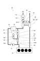
- FIG. 1 is a schematic configuration diagram showing an example of an internal combustion engine with a supercharger according to this embodiment.
- An internal combustion engine 10 with a supercharger shown in FIG. 1 includes an internal combustion engine 20, an intake passage 30 whose downstream end in the intake gas flow direction Din is connected to the internal combustion engine 10, and an upstream end in the exhaust gas flow direction Dex. And an exhaust passage 40 connected to the internal combustion engine 20.
- a compressor 50 ⁇ / b> C constituting a part of the supercharger 50 is arranged in the intake passage 30, and a turbine 50 ⁇ / b> T constituting a part of the supercharger 50 is arranged in the exhaust passage 40.
- An intercooler 60 is disposed in the intake passage 30 located downstream of the compressor 50C in the intake gas flow direction Din in order to cool the intake gas that has become hot due to compression by the compressor 50C.
- the intercooler 60 is provided with a condensed water discharge port 62 for discharging condensed water generated by condensation of moisture in the intake gas cooled when the intake gas passes through the intercooler 60 to the outside.
- a throttle valve 70 is disposed in the intake passage 30 located downstream of the intercooler 60 in the intake gas flow direction Din.
- the internal combustion engine 20 is disposed downstream of the throttle valve 70 in the intake passage 30.
- the EGR passage 80 connects the intake passage 30 located upstream of the compressor 50C in the intake gas flow direction Din and the exhaust passage 40 located downstream of the turbine 50T in the exhaust gas flow direction Dex. Is arranged. Further, a valve 90 is provided in the EGR passage 80, and a valve 100 is provided on the upstream side of the connection portion 80CN of the intake passage 30 with the EGR passage 80. The valves 90, 100 are opened. By adjusting the degree, the degree of mixing of the outside air (air) taken from the inlet of the intake passage 30 and the exhaust gas recirculated from the exhaust passage 40 to the intake passage 30 through the EGR passage 80 is determined. A filter 110 is provided upstream of the position where the valve 100 of the intake passage 30 is disposed.
- the exhaust gas contains acidic components such as sulfur oxides and nitrogen oxides.
- the intake gas flowing through the intake passage 30 includes exhaust gas circulated to the intake passage 30 via the EGR passage 80 in addition to outside air (air). For this reason, the condensed water generated in the intercooler 60 becomes an acidic aqueous solution containing water and an acidic component contained in the exhaust gas. Further, the supercharged internal combustion engine 10 of the present embodiment may not have the EGR passage 80, but even in such a case, an urban area where there is a lot of traffic congestion (particularly a low degree of purification and a large amount of sulfur components, etc.).
- the intercooler 60 If the condensed water exhibiting such acidity continues to stay in the intercooler 60, the intercooler 60 is corroded, so the condensed water needs to be discharged to the outside of the intercooler 60. For this reason, the condensed water is discharged from the condensed water discharge port 62 of the intercooler 60 to the outside. At this time, as disclosed in Patent Document 1, if a passage for connecting the condensed water discharge port 62 to the intake passage 30 located between the throttle valve 70 and the internal combustion engine 20 is provided, the intercooler 60 can be used. The generated condensed water can flow into the internal combustion engine 20.
- the ejector 120 includes a driving gas supply port 120D that supplies a driving gas, a liquid suction port 120L that sucks a liquid, and a mixed gas discharge port 120M that discharges a mixed gas of the driving gas and the atomized liquid.
- the driving gas supply passage 120 connects the driving gas supply port 120D to the intake passage 30 positioned between the intercooler 60 and the compressor 50C, and the condensed water discharge passage 140 causes the liquid suction port 120L to connect to the condensed water discharge port 62.
- the mixed gas discharge passage 150 connects the mixed gas discharge port 120 ⁇ / b> M to the intake passage 30 positioned between the throttle valve 70 and the internal combustion engine 20. Therefore, the condensed water flowing into the ejector 120 from the condensed water discharge passage 140 can be atomized in the ejector 120 and then flowed into the internal combustion engine 20 through the mixed gas discharge passage 150 and the intake passage 30.
- the condensed water does not always continue to be generated in large quantities. Therefore, in practice, the condensed water generated in the intercooler 60 is once stored in the tank, and then the ejector 120 is operated as appropriate to introduce the condensed water stored in the tank into the internal combustion engine 20. Is preferred. Therefore, in order to perform such processing, for example, a valve 160 is provided in the driving gas supply passage 130, and the condensed water discharge passage 140 is provided along the direction from the condensed water discharge port 62 side to the liquid suction port 120L side. Thus, the condensed water storage tank 170 and the valve 180 can be provided in this order.
- the timing of opening and closing of the valves 160 and 180 and the opening degree are appropriately controlled according to the supercharging pressure of the intake gas flowing through the intake passage 30 downstream of the compressor 50C, so that the condensed water storage tank 170 can be opened.
- the stored condensed water can be atomized and then introduced into the internal combustion engine 20.
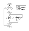
- the operating conditions of the ejector 120 used in the supercharged internal combustion engine 10 shown in FIG. 1 can be set as appropriate, but can be controlled, for example, according to the control flowchart shown in FIG.
- the supercharging pressure P of the intake passage 30 between the compressor 50C and the intercooler 60 is compared with the valve opening / closing threshold supercharging pressure P0 for determining the opening / closing of the valves 160, 180.
- the opening / closing threshold supercharging pressure P0 is exceeded, the ejector 120 starts to operate by opening the valves 160 and 180.
- the valves 160 and 180 are kept closed, and the ejector 120 does not operate.
- the supercharging pressure P varies depending on the supercharged internal combustion engine 10 and its operating condition, but is usually in the range of 0 kPa to 90 kPa.
- the valve opening / closing threshold supercharging pressure P0 is appropriately set within a range exceeding 0 kPa and smaller than the maximum value of the supercharging pressure P.
- the intake gas flowing through the intake passage 30 is supplied into the ejector 120 from the drive gas supply port 120 ⁇ / b> D via the drive gas supply passage 130, and the condensation that has been stored in the condensed water storage tank 170. Water is sucked into the ejector 120 from the liquid suction port 120L side through the condensed water discharge passage 140. The condensed water atomized in the ejector 120 is introduced into the internal combustion engine 20 through the mixed gas discharge passage 150 and the intake passage 30 positioned between the throttle valve 70 and the internal combustion engine 20.
- whether or not to continue the state in which the valves 160 and 180 are opened is first determined based on whether or not the supercharging pressure P is smaller than the valve opening / closing threshold supercharging pressure P0. Is smaller than the valve opening / closing threshold supercharging pressure P0, the valves 160 and 180 are closed again, and the operation of the ejector 120 is stopped. On the other hand, when the supercharging pressure P is not smaller than the valve opening / closing threshold supercharging pressure P0, the valves 160 and 180 are kept open.
- the accumulated time T int from when the valves 160 and 180 are opened is A secondary determination is made as to whether or not the open / close threshold time T0 is exceeded.
- the valves 160 and 180 are closed again, and the operation of the ejector 120 is stopped.
- the accumulated time T int does not exceed the valve opening / closing threshold time T0, the state in which the valves 160 and 180 are opened is continued.
- the operation pattern of the ejector 120 is such that when the supercharging pressure P exceeds the valve opening / closing threshold supercharging pressure P0, the ejector 120 starts operating, and the supercharging pressure P is set to When the operation is stopped by lowering the supercharging pressure P0 and when the supercharging pressure P exceeds the valve opening / closing threshold supercharging pressure P0 as shown in FIG.
- the ejector 120 stops operating when T int exceeds the valve opening / closing threshold time T0 There are two patterns in which the ejector 120 stops operating when T int exceeds the valve opening / closing threshold time T0.
- the driving gas supply port 120D is connected to the intake passage 30 located between the compressor 50C and the intercooler 60, but the driving gas supply port 120D is connected to the compressor 50C and the throttle valve 70. It can be connected to any position of the intake passage 30 located between them.
- the driving gas supply port 120D is provided with the intake passage 30 (intercooler upstream passage) located between the compressor 50C and the intercooler 60 and / or the intake passage 30 (intercooler) located between the intercooler 60 and the throttle valve 70.
- the downstream side passage it is more preferable to connect to the intercooler upstream side passage as illustrated in FIG.
- the ejector 120 a known ejector can be used as appropriate. That is, the ejector 120 includes at least a driving gas supply port 120D, a liquid suction port 120L, and a mixed gas discharge port 120M, and injects a driving gas supplied from the driving gas supply port 120D therein, thereby sucking liquid into the liquid As long as it has a function of discharging and mixing this mixed gas from the mixed gas discharge port 120M, the internal structure of the mixed gas is not limited. There may be.
- FIG. 4 is a schematic cross-sectional view showing an example of the internal structure of an ejector 120 used in the supercharged internal combustion engine 10 of the present embodiment.
- a suction chamber 122 that communicates with the liquid suction port 120L
- a nozzle 124 that communicates with the driving gas supply port 120D
- a nozzle tip 124T projects into the suction chamber 122.
- a tubular diffuser portion 126 having one end communicating with the suction chamber 122 and the other end communicating with the mixed gas discharge port 120M is provided.
- the ejector 120 has a cylindrical shape.
- a drive gas supply port 120 ⁇ / b> D is provided on one end side of the ejector 120, and a mixed gas discharge port 120 ⁇ / b> M is provided on the other end side of the ejector 120.
- a liquid inlet 120L is provided in the main body.
- the center point of the driving gas supply port 120D, the center axis of the nozzle 124, the center axis of the diffuser portion 126, and the center point of the mixed gas discharge port 120M substantially coincide with the center axis C of the ejector 120.
- the dimensional shape of each part of the ejector 120 is appropriately selected according to the flow rate / pressure of the driving gas supplied from the driving gas supply port 120D and the flow rate / pressure of the liquid sucked from the liquid suction port 120L.
- a negative pressure is generated by ejecting the driving gas from the nozzle tip portion 124T of the nozzle 124 into the suction chamber 122, so that the liquid suction port 120L side enters the suction chamber 122. And liquid is inhaled. Then, the liquid sucked into the suction chamber 122 is atomized by the high-speed driving gas flow ejected from the nozzle tip portion 124T as shown by the dotted line D in the drawing, and at the same time, mixed with the driving gas. The Then, the mixed gas containing the driving gas and the atomized liquid is discharged from the vicinity of the nozzle tip portion 124T in the suction chamber 122 through the diffuser portion 126 and from the mixed gas discharge port 120M side.
- the pressure when the ejector 120 is operated is set as follows. First, the maximum value of the supply pressure of the drive gas (pressure at the drive gas supply port 120D) is generally 90 kPa or less, and the minimum value is, for example, when performing the control illustrated in FIG.
- the valve opening / closing threshold boost pressure P0 of the valve 160 is set.
- the pressure at the liquid suction port 120L is also set to be lower than the supply pressure of the driving gas. Further, the pressure at the driving gas supply port 120D closer to the compressor 50C side becomes larger than the pressure at the mixed gas discharge port 120M.
- the ejector 120 does not have a moving part such as a rotational movement or a piston movement, and has a very simple structure. Therefore, even if the ejector 120 is operated for a long period of time, the possibility of failure is extremely small, adjustment is unnecessary, maintenance is very simple, space saving, and cost burden is extremely small. .
- the ejector 120 As a material constituting the ejector 120, known mechanical structural materials such as carbon steel, stainless steel, cast iron, carbon, resin and the like can be appropriately used.
- driving gas intake gas
- liquid condensed water
- the driving gas includes exhaust gas taken from outside the vehicle (especially in urban areas) and / or exhaust gas discharged from the internal combustion engine 20 and passing through the EGR passage 80.
- this exhaust gas contains acidic components such as sulfur oxides, the liquid becomes an acidic aqueous solution containing water and acidic components.
- the material constituting the ejector 120 is made of a material that corrodes with an acidic aqueous solution, if the ejector 120 is used over a long period of time, the hole will be opened or damaged due to corrosion, and the function as the ejector 120 will be exhibited. It may not be possible.
- At least a part of the ejector 120 is made of an acid resistant material.
- the entire ejector 120 may be made of an acid resistant material.
- an acid-resistant material a known acid-resistant material can be used.
- stainless steel, resin, ceramics, carbon and the like can be used.
- the piping constituting the condensed water discharge passage 140 and the mixed gas discharge passage 150, the condensed water storage tank 170, and the valve 180 are also made of an acid resistant material.
- any known intercooler 60 can be used as long as it has a condensed water discharge port 62 that collects condensed water generated in the intercooler 60 and discharges it to the outside.
- the condensed water discharge port 62 is disposed at a location where condensed water condensed in the intercooler 60 flows or where this condensed water accumulates.
- a valve for opening and closing the condensed water discharge port 62 is preferably provided.
- the structure and operating mechanism of the valve are not particularly limited.
- the valve opens and closes in conjunction with the movement of the float that rises and falls according to the water level of the condensed water accumulated in the intercooler 60 when the internal combustion engine 20 is stopped. It may be a float valve.
- the valve expands or contracts according to the temperature in the intercooler 60, and closes the valve when the temperature of the intercooler 60 is higher than a predetermined temperature.
- the temperature of 60 is lower than a predetermined temperature, it may be connected to driving means for opening the valve.
- the drive means can be any member that changes its volume, length, or shape according to temperature and can drive the valve, such as metal, wax, or bimetal. Etc. are available.
Landscapes
- Engineering & Computer Science (AREA)
- Chemical & Material Sciences (AREA)
- Combustion & Propulsion (AREA)
- Mechanical Engineering (AREA)
- General Engineering & Computer Science (AREA)
- Physics & Mathematics (AREA)
- Thermal Sciences (AREA)
- Exhaust-Gas Circulating Devices (AREA)
- Supercharger (AREA)
Abstract
インタークーラーにおいて発生した凝縮水を内燃機関に還流させる場合においても、ウォーターハンマー現象等の発生を抑制して内燃機関への悪影響を抑制すること。 下流端に内燃機関(20)が接続された吸気通路(30)の上流側から下流側へと、過給機(50)の一部を構成するコンプレッサ(50C)、インタークーラー(60)、スロットルバルブ(70)がこの順に配置されると共に、エゼクター(120)を備え、エゼクター(120)の駆動ガス供給口(120D)がコンプレッサ(50C)およびスロットルバルブ(70)の間に位置する吸気通路(30)に接続され、エゼクター(120)の液体吸入口(120L)がインタークーラー(60)の凝縮水排出口(62)に接続され、エゼクター(120)の混合ガス排出口(120M)がスロットルバルブ(70)および内燃機関(20)の間に位置する吸気通路(30)に接続されている過給機付き内燃機関及びこれに用いるエゼクター。
Description
本発明は、過給機付き内燃機関および過給機付き内燃機関用エゼクターに関するものである。
過給機付きの内燃機関では、排気通路にタービンを配置し、吸気通路にコンプレッサを配置した過給機を備えており、また、吸気通路には、コンプレッサにより圧縮され、高温になった吸気ガスを冷却するために、コンプレッサの下流側にインタークーラーが設けられている。また、近年では、環境対応等の観点から、タービンよりも下流側の排気通路とコンプレッサよりも上流側の吸気通路とを接続し内燃機関からの排気ガスの一部を吸気通路に還流させるEGR通路をさらに備えた過給機付きの内燃機関も利用されている。
このような過給機付き内燃機関では、インタークーラーにおいて吸気ガスが冷却されることにより凝縮水が発生する。そして、EGR通路をさらに備えた過給機付きの内燃機関では、EGR通路から吸気通路へと流れ込んだEGRガス中に硫黄成分等が含まれる。したがって、凝縮水中にもこれらの成分が含まれることとなるため、これらの成分によりインタークーラーが腐食される。
このような問題に鑑みて、特許文献1では、インタークーラーにおいて発生した凝縮水をより確実に排出できる技術が提案されている。そして、この技術では、たとえば、インタークーラーと内燃機関およびスロットルバルブの間に位置する吸気通路とを接続する排出路を設けることで、インタークーラーにおいて発生した凝縮水を内燃機関の気筒内に流入させて蒸発させている。
しかしながら、インタークーラーにおいて発生した凝縮水を、排出路を利用して内燃機関へとそのまま還流させる方法では、ウォーターハンマー現象などが発生し、内燃機関に悪影響を及ぼす可能性がある。
本発明は上記事情に鑑みてなされたものであり、インタークーラーにおいて発生した凝縮水を内燃機関に還流させる場合においても、ウォーターハンマー現象などの発生を抑制して内燃機関への悪影響を抑制する過給機付き内燃機関および過給機付き内燃機関用エゼクターを提供することを課題とする。
上記課題は以下の本発明により達成される。すなわち、
本発明の過給機付き内燃機関は、内燃機関と、吸気ガス流れ方向の下流側端部が内燃機関に接続された吸気通路と、過給機の一部を構成すると共に、吸気通路に配置されたコンプレッサと、凝縮水排出口を備えると共に、コンプレッサよりも吸気ガス流れ方向の下流側に位置する吸気通路に配置されたインタークーラーと、インタークーラーよりも吸気ガス流れ方向の下流側に位置する吸気通路に配置されたスロットルバルブと、駆動ガスを供給する駆動ガス供給口、液体を吸入する液体吸入口および駆動ガスと霧化した液体との混合ガスを排出する混合ガス排出口を備え、駆動ガス供給口がコンプレッサおよびスロットルバルブの間に位置する吸気通路に接続され、液体吸入口が凝縮水排出口に接続され、混合ガス排出口がスロットルバルブおよび内燃機関の間に位置する吸気通路に接続されたエゼクターと、を備えることを特徴とする。
本発明の過給機付き内燃機関は、内燃機関と、吸気ガス流れ方向の下流側端部が内燃機関に接続された吸気通路と、過給機の一部を構成すると共に、吸気通路に配置されたコンプレッサと、凝縮水排出口を備えると共に、コンプレッサよりも吸気ガス流れ方向の下流側に位置する吸気通路に配置されたインタークーラーと、インタークーラーよりも吸気ガス流れ方向の下流側に位置する吸気通路に配置されたスロットルバルブと、駆動ガスを供給する駆動ガス供給口、液体を吸入する液体吸入口および駆動ガスと霧化した液体との混合ガスを排出する混合ガス排出口を備え、駆動ガス供給口がコンプレッサおよびスロットルバルブの間に位置する吸気通路に接続され、液体吸入口が凝縮水排出口に接続され、混合ガス排出口がスロットルバルブおよび内燃機関の間に位置する吸気通路に接続されたエゼクターと、を備えることを特徴とする。
本発明の過給機付き内燃機関の一実施形態は、排気ガス流れ方向の上流側端部が内燃機関に接続された排気通路と、過給機の一部を構成すると共に、排気通路に配置されたタービンと、コンプレッサよりも吸気ガス流れ方向の上流側に位置する吸気通路およびタービンよりも排気ガス流れ方向の下流側に位置する排気通路を接続するEGR通路と、をさらに備えることが好ましい。
本発明の過給機付き内燃機関用エゼクターは、駆動ガスを供給する駆動ガス供給口、液体を吸入する液体吸入口および駆動ガスと霧化した液体との混合ガスを排出する混合ガス排出口を備え、作動時に、駆動ガス供給口側から供給される駆動ガスが空気を含み、液体吸入口側から吸入される前記液体が水を含む、ことを特徴とする。
本発明の過給機付き内燃機関用エゼクターの一実施形態は、作動時に、駆動ガス供給口側から供給される駆動ガスが空気と内燃機関から排出された排気ガスとを含み、液体吸入口側から吸入される液体が水と排気ガス中に含まれる酸性成分とを含む、ことが好ましい。
本発明の過給機付き内燃機関用エゼクターの他の実施形態は、作動時における駆動ガスの供給圧力の最大値が90kPa以下であることが好ましい。
本発明の過給機付き内燃機関用エゼクターの他の実施形態は、液体吸入口から混合ガス排出口まで連続する流路の内壁面が、耐酸性材料から構成されていることが好ましい。
本発明によれば、インタークーラーにおいて発生した凝縮水を内燃機関に還流させる場合においても、ウォーターハンマー現象などの発生を抑制して内燃機関への悪影響を抑制する過給機付き内燃機関および過給機付き内燃機関用エゼクターを提供することができる。
図1は、本実施形態の過給機付き内燃機関の一例を示す概略構成図である。図1に示す過給機付き内燃機関10は、内燃機関20と、吸気ガス流れ方向Dinの下流側端部が内燃機関10に接続された吸気通路30と、排気ガス流れ方向Dexの上流側端部が内燃機関20に接続された排気通路40とを有している。そして、吸気通路30には、過給機50の一部を構成するコンプレッサ50Cが配置され、排気通路40には、過給機50の一部を構成するタービン50Tが配置されている。また、コンプレッサ50Cよりも吸気ガス流れ方向Dinの下流側に位置する吸気通路30には、コンプレッサ50Cによる圧縮によって、高温となった吸気ガスを冷却するためにインタークーラー60が配置されている。このインタークーラー60には、インタークーラー60内を吸気ガスが通過する際に冷却された吸気ガス中の水分が凝縮して発生した凝縮水を外部に排出するための凝縮水排出口62が設けられている。さらに、インタークーラー60よりも吸気ガス流れ方向Dinの下流側に位置する吸気通路30にはスロットルバルブ70が配置されている。そして吸気通路30のスロットルバルブ70の下流側には内燃機関20が配置されている。
さらに、EGR通路80が、コンプレッサ50Cよりも吸気ガス流れ方向Dinの上流側に位置する吸気通路30と、タービン50Tよりも排気ガス流れ方向Dexの下流側に位置する排気通路40とを接続するように配置されている。また、EGR通路80にはバルブ90が設けられており、吸気通路30のEGR通路80との接続部分80CNよりも上流側には、バルブ100が設けられており、これらのバルブ90、100の開度を調整することで、吸気通路30の入口から取り入れられた外気(空気)と、排気通路40からEGR通路80を経て吸気通路30へと再び循環する排気ガスとの混合度合いが決定される。また、吸気通路30のバルブ100が配置された位置よりも上流側にはフィルタ110が設けられる。
ここで、排気ガス中には、硫黄酸化物や窒素酸化物等の酸性成分が含まれる。また、吸気通路30を流れる吸気ガス中には、外気(空気)以外にEGR通路80を経由して吸気通路30へと循環した排気ガスも含まれる。このため、インタークーラー60において発生した凝縮水は、水と排気ガス中に含まれる酸性成分とを含む酸性水溶液となる。また、本実施形態の過給機付き内燃機関10はEGR通路80を有していなくてもよいが、このような場合でも交通渋滞の多い都市部(特に精製度が低く硫黄成分等を多く含む燃料の使用が許容されていたり、排気ガス対策が不十分な自動車が多く走っている発展途上国の都市部)では、吸気通路30の入口から取り入れられた外気(空気)中に高濃度の酸性成分が含まれ易くなる。したがって、EGR通路80が無い場合でも、インタークーラー60において発生した凝縮水は酸性水溶液となる可能性がある。
このような酸性を示す凝縮水が、インタークーラー60内に滞留し続けると、インタークーラー60が腐食するため、凝縮水をインタークーラー60の外部へと排出する必要がある。このため、凝縮水は、インタークーラー60の凝縮水排出口62から外部へと排出される。この際、特許文献1にも開示されているように、凝縮水排出口62とスロットルバルブ70および内燃機関20の間に位置する吸気通路30とを接続する通路を設ければ、インタークーラー60内で発生した凝縮水を、内燃機関20中に流入させることができる。しかし、凝縮水をそのまま内燃機関20中に流入させただけではウォーターハンマー現象等が発生し、内燃機関20に悪影響を与える可能性がある。しかしながら、本実施形態の過給機付き内燃機関20では、エゼクター120を用いることにより凝縮水を霧化させた状態で内燃機関20内へと導入するため、上述したような問題の発生を抑制することができる。
ここで、エゼクター120は、駆動ガスを供給する駆動ガス供給口120D、液体を吸入する液体吸入口120Lおよび駆動ガスと霧化した液体との混合ガスを排出する混合ガス排出口120Mを備えている。そして、駆動ガス供給路130により、駆動ガス供給口120Dが、インタークーラー60およびコンプレッサ50Cの間に位置する吸気通路30に接続され、凝縮水排出通路140により、液体吸入口120Lが凝縮水排出口62に接続され、混合ガス排出通路150により、混合ガス排出口120Mがスロットルバルブ70および内燃機関20の間に位置する吸気通路30に接続される。このため、凝縮水排出通路140からエゼクター120に流入した凝縮水を、エゼクター120内で霧化した後、混合ガス排出通路150および吸気通路30を経て内燃機関20内へと流入させることができる。
なお、内燃機関20の稼働中において、凝縮水は、常時、大量に発生し続けるわけではない。このため、実用上は、インタークーラー60内で発生した凝縮水をタンクに一旦溜めておいた上で、適宜、エゼクター120を作動させてタンク内に溜まった凝縮水を内燃機関20内に導入することが好ましい。よって、このような処理を行うために、たとえば、駆動ガス供給路130にバルブ160を設け、凝縮水排出通路140には、凝縮水排出口62側から液体吸入口120L側へと向う方向に沿って、凝縮水貯留タンク170およびバルブ180をこの順に設けることができる。この場合、コンプレッサ50Cよりも下流側の吸気通路30を流れる吸気ガスの過給圧に応じて、バルブ160、180の開閉のタイミングや開度を適宜制御することで、凝縮水貯留タンク170内に貯留された凝縮水を霧化した上で内燃機関20へと導入できる。
ここで、図1に示す過給機付き内燃機関10において用いられるエゼクター120の作動条件は、適宜設定することができるが、たとえば、図2に示す制御フローチャートに従って制御することができる。
まず、コンプレッサ50Cとインタークーラー60との間における吸気通路30の過給圧Pと、バルブ160、180の開閉を決定するためのバルブ開閉閾過給圧P0とを比較し、過給圧Pがバルブ開閉閾過給圧P0を超えている場合は、バルブ160、180を開けることでエゼクター120が作動し始める。一方、過給圧Pがバルブ開閉閾過給圧P0を超えていない場合は、バルブ160、180は閉められたままの状態を維持するため、エゼクター120は作動しない。なお、過給圧Pは、過給機付き内燃機関10やその稼働状況に応じて変動するが、通常、0kPa~90kPaの範囲内である。また、バルブ開閉閾過給圧P0は、0kPaを超え過給圧Pの最大値よりも小さい範囲内において適宜設定される。
バルブ160、180を開けた場合、吸気通路30を流れる吸気ガスが、駆動ガス供給路130を経て駆動ガス供給口120D側からエゼクター120内に供給され、凝縮水貯留タンク170に貯留されていた凝縮水が、凝縮水排出通路140を経て液体吸入口120L側からエゼクター120内へと吸い込まれる。そして、エゼクター120内にて霧化された凝縮水は、混合ガス排出通路150およびスロットルバルブ70と内燃機関20との間に位置する吸気通路30を経て内燃機関20内へと導入される。
ここで、バルブ160、180を開けた状態を継続するか否かは、まず過給圧Pがバルブ開閉閾過給圧P0よりも小さくなっているか否かにより1次判断し、過給圧Pがバルブ開閉閾過給圧P0よりも小さくなっている場合は、バルブ160、180を再び閉じて、エゼクター120の作動を停止させる。一方、過給圧Pがバルブ開閉閾過給圧P0よりも小さくなっていない場合は、バルブ160、180を開いた状態を継続する。
また、1次判断の結果、過給圧Pがバルブ開閉閾過給圧P0よりも大きい状態を維持し続けている場合は、バルブ160、180を開けた時点からの積算時間Tintが、バルブ開閉閾時間T0を超えているか否かについて2次判断する。その結果、積算時間Tintが、バルブ開閉閾時間T0を超えた場合は、バルブ160、180を再び閉じて、エゼクター120の作動を停止させる。一方、積算時間Tintが、バルブ開閉閾時間T0を超えていない場合は、バルブ160、180を開いた状態を継続する。
したがって、エゼクター120の作動パターンは、図3(A)に示すように過給圧Pがバルブ開閉閾過給圧P0を超えることによりエゼクター120が作動を開始し、過給圧Pがバルブ開閉閾過給圧P0を下回ることより作動を停止する場合と、図3(B)に示すように過給圧Pがバルブ開閉閾過給圧P0を超えることによりエゼクター120が作動を開始し、積算時間Tintがバルブ開閉閾時間T0を超えることによりエゼクター120が作動を停止する場合の2つのパターンがある。
なお、図1に示す例では、駆動ガス供給口120Dは、コンプレッサ50Cおよびインタークーラー60の間に位置する吸気通路30に接続されているが、駆動ガス供給口120Dは、コンプレッサ50Cおよびスロットルバルブ70の間に位置する吸気通路30の任意の位置に接続できる。この場合、駆動ガス供給口120Dは、コンプレッサ50Cおよびインタークーラー60の間に位置する吸気通路30(インタークーラー上流側通路)、ならびに/または、インタークーラー60およびスロットルバルブ70の間に位置する吸気通路30(インタークーラー下流側通路)に接続できるが、図1に例示したようにインタークーラー上流側通路に接続することがより好ましい。駆動ガス供給口120Dをインタークーラー下流側通路に接続した場合、吸気ガスがインタークーラー60を通過した際に圧力損失が発生するため、エゼクター120を作動させるために必要な駆動ガスの供給圧力が低下するためである。
なお、エゼクター120としては、公知のエゼクターを適宜利用できる。すなわち、エゼクター120は、駆動ガス供給口120D、液体吸入口120Lおよび混合ガス排出口120Mを少なくとも備え、その内部において駆動ガス供給口120Dから供給された駆動ガスを噴射することで、液体を液体吸入口120Lから吸込むとともに霧化して駆動ガスと霧化した液体とを混合した混合ガスとし、この混合ガスを混合ガス排出口120Mから排出する機能を有するものであれば、その内部構造は如何様であってもよい。
図4は、本実施形態の過給機付き内燃機関10に用いられるエゼクター120の内部構造の一例を示す模式断面図である。このエゼクター120の内部には、液体吸入口120Lと連通する吸入室122と、駆動ガス供給口120Dと連通すると共に、吸入室122内にノズル先端部124Tが突出するように設けられたノズル124と、一端が吸入室122と連通し、他端が混合ガス排出口120Mと連通する管状のディフューザー部126とが設けられている。そして、エゼクター120は筒状を成しており、エゼクター120の一端側に駆動ガス供給口120Dが設けられ、エゼクター120の他端側に混合ガス排出口120Mが設けられ、エゼクター120の外周面側に液体吸入口120Lが設けられている。また、駆動ガス供給口120Dの中心点、ノズル124の中心軸、ディフューザー部126の中心軸および混合ガス排出口120Mの中心点は、エゼクター120の中心軸Cと略一致している。ここで、エゼクター120の各部の寸法形状は、駆動ガス供給口120Dから供給される駆動ガスの流量・圧力および液体吸入口120Lから吸い込まれる液体の流量・圧力等に応じて適宜選択される。
図4に示すエゼクター120を作動させた場合、ノズル124のノズル先端部124Tから吸入室122内へと駆動ガスを噴出させることで負圧が生じるため、液体吸入口120L側から吸入室122内へと液体が吸入される。そして吸入室122内へと吸入された液体は、図中の点線D内に示されるようにノズル先端部124Tから噴出される高速の駆動ガス流によって霧化されると同時に、駆動ガスと混合される。そして駆動ガスと霧化された液体とを含む混合ガスが、吸入室122内のノズル先端部124T部近傍からディフューザー部126を経て、混合ガス排出口120M側から排出される。
なお、エゼクター120の作動時における圧力は以下のように設定される。まず、駆動ガスの供給圧力(駆動ガス供給口120Dにおける圧力)の最大値は、一般的には90kPaあるいはそれ以下であり、最小値は、たとえば、図3に例示するような制御を行う場合はバルブ160のバルブ開閉閾過給圧P0に設定される。また、液体吸入口120Lにおける圧力も、駆動ガスの供給圧力よりも低くなるように設定される。また、コンプレッサ50C側により近い駆動ガス供給口120Dにおける圧力は、混合ガス排出口120Mにおける圧力よりも大きくなる。
エゼクター120は、回転運動やピストン運動などの運動部分を有していない上に構造も極めて簡単である。このため長期に渡ってエゼクター120を作動させても故障の可能性が極めて小さく、調整が不要であり、保守も極めて簡単であり、省スペースであり、また、コスト負担も極めて小さいというメリットがある。
エゼクター120を構成する材料としては、炭素鋼、ステンレス鋼、鋳鉄、カーボン、樹脂等の公知の機械構造用材料が適宜利用できる。なお、エゼクター120を作動させた場合、駆動ガス供給口120D側から空気を含む駆動ガス(吸気ガス)が供給され、液体吸入口120L側から水を含む液体(凝縮水)が吸入される。この際、駆動ガス中には、(特に、都市部において)車外から取り入れられた排気ガス、および/または、内燃機関20から排出されEGR通路80を経由してきた排気ガスが含まれる。そして、この排気ガス中には硫黄酸化物などの酸性成分が含まれるため、液体は、水と酸性成分とを含む酸性水溶液となる。したがって、エゼクター120を構成する材料が、酸性水溶液によって腐食する材料からなる場合は、長期に渡ってエゼクター120を使用すると腐食により穴が開いたり破損したりすることで、エゼクター120としての機能を発揮できなくなる可能性がある。
したがって、このような問題の発生を防ぐ観点からは、エゼクター120の少なくとも一部分、すなわち、液体吸入口120Lから混合ガス排出口120Mまで連続する流路の内壁面が、耐酸性材料から構成されていることが好ましく、エゼクター120全体が耐酸性材料から構成されていてもよい。このような耐酸性材料としては、公知の耐酸性材料を用いることができるが、たとえば、ステンレス鋼、樹脂、セラミックス、カーボンなどが利用できる。なお、同様の観点からは、凝縮水排出通路140および混合ガス排出通路150を構成する配管、凝縮水貯留タンク170、バルブ180も耐酸性材料から構成されることが好ましい。
インタークーラー60としては、インタークーラー60内で発生した凝縮水を集めて外部に排出する凝縮水排出口62を備えたものであれば公知のインタークーラー60が適宜利用できる。この凝縮水排出口62は、インタークーラー60内で凝縮する凝縮水が流れる箇所もしくはこの凝縮水が溜まる箇所に配置される。また、凝縮水排出口62を開閉するためのバルブが設けられることが好ましい。
このバルブの構造・作動機構等は特に限定されるものではないが、たとえば、内燃機関20の停止時にインタークーラー60内に溜まった凝縮水の水位に応じて浮き沈みするフロートの動きに連動して開閉するフロート弁であってもよい。また、バルブは、特許文献1に開示された技術のように、インタークーラー60内の温度に応じて膨張または収縮し、かつ、インタークーラー60の温度が所定温度よりも高いときにバルブを閉塞し、インタークーラー60の温度が所定温度よりも低いときにバルブを開口させる駆動手段に接続されていてもよい。このようなバルブおよび駆動手段としては、たとえば、サーモスタットと同じ構造のものを用いることができる。なお、駆動手段は、温度に応じて体積、長さまたは形状が変化し、かつ、バルブを駆動させ得る部材であればどのような部材でも用いることができ、たとえば、金属、ワックス、あるいは、バイメタルなどが利用できる。
10 :過給機付き内燃機関
20 :内燃機関
30 :吸気通路
40 :排気通路
50 :過給機
50C :コンプレッサ
50T :タービン
60 :インタークーラー
62 :凝縮水排出口
70 :スロットルバルブ
80 :EGR通路
80CN :接続部分
90、100 :バルブ
110 :フィルタ
120 :エゼクター
120D :駆動ガス供給口
120L :液体吸入口
120M :混合ガス排出口
122 :吸入室
124 :ノズル
124T :ノズル先端部
126 :ディフューザー部
130 :駆動ガス供給路
140 :凝縮水排出通路
150 :混合ガス排出通路
160 :バルブ
170 :凝縮水貯留タンク
180 :バルブ
20 :内燃機関
30 :吸気通路
40 :排気通路
50 :過給機
50C :コンプレッサ
50T :タービン
60 :インタークーラー
62 :凝縮水排出口
70 :スロットルバルブ
80 :EGR通路
80CN :接続部分
90、100 :バルブ
110 :フィルタ
120 :エゼクター
120D :駆動ガス供給口
120L :液体吸入口
120M :混合ガス排出口
122 :吸入室
124 :ノズル
124T :ノズル先端部
126 :ディフューザー部
130 :駆動ガス供給路
140 :凝縮水排出通路
150 :混合ガス排出通路
160 :バルブ
170 :凝縮水貯留タンク
180 :バルブ
Claims (6)
- 内燃機関と、
吸気ガス流れ方向の下流側端部が前記内燃機関に接続された吸気通路と、
過給機の一部を構成すると共に、前記吸気通路に配置されたコンプレッサと、
凝縮水排出口を備えると共に、前記コンプレッサよりも前記吸気ガス流れ方向の下流側に位置する前記吸気通路に配置されたインタークーラーと、
前記インタークーラーよりも前記吸気ガス流れ方向の下流側に位置する前記吸気通路に配置されたスロットルバルブと、
駆動ガスを供給する駆動ガス供給口、液体を吸入する液体吸入口および前記駆動ガスと霧化した前記液体との混合ガスを排出する混合ガス排出口を備え、
前記駆動ガス供給口が前記コンプレッサおよび前記スロットルバルブの間に位置する前記吸気通路に接続され、前記液体吸入口が前記凝縮水排出口に接続され、前記混合ガス排出口が前記スロットルバルブおよび前記内燃機関の間に位置する前記吸気通路に接続されたエゼクターと、
を備えることを特徴とする過給機付き内燃機関。 - 請求項1に記載の過給機付き内燃機関において、
排気ガス流れ方向の上流側端部が前記内燃機関に接続された排気通路と、
前記過給機の一部を構成すると共に、前記排気通路に配置されたタービンと、
前記コンプレッサよりも前記吸気ガス流れ方向の上流側に位置する前記吸気通路および前記タービンよりも前記排気ガス流れ方向の下流側に位置する前記排気通路を接続するEGR通路と、
をさらに備えることを特徴とする過給機付き内燃機関。 - 駆動ガスを供給する駆動ガス供給口、液体を吸入する液体吸入口および前記駆動ガスと霧化した前記液体との混合ガスを排出する混合ガス排出口を備え、
作動時に、前記駆動ガス供給口側から供給される前記駆動ガスが空気を含み、前記液体吸入口側から吸入される前記液体が水を含む、ことを特徴とする過給機付き内燃機関用エゼクター。 - 請求項3に記載の過給機付き内燃機関用エゼクターにおいて、
作動時に、前記駆動ガス供給口側から供給される前記駆動ガスが前記空気と内燃機関から排出された排気ガスとを含み、前記液体吸入口側から吸入される前記液体が前記水と前記排気ガス中に含まれる酸性成分とを含む、ことを特徴とする過給機付き内燃機関用エゼクター。 - 請求項3または4に記載の過給機付き内燃機関用エゼクターにおいて、
作動時における前記駆動ガスの供給圧力の最大値が90kPa以下であることを特徴とする過給機付き内燃機関用エゼクター。 - 請求項3~5のいずれか1つに記載の過給機付き内燃機関用エゼクターにおいて、
前記液体吸入口から前記混合ガス排出口まで連続する流路の内壁面が、耐酸性材料から構成されていることを特徴とする内燃機関用エゼクター。
Applications Claiming Priority (2)
| Application Number | Priority Date | Filing Date | Title |
|---|---|---|---|
| JP2013-268491 | 2013-12-26 | ||
| JP2013268491A JP6549350B2 (ja) | 2013-12-26 | 2013-12-26 | 過給機付き内燃機関 |
Publications (1)
| Publication Number | Publication Date |
|---|---|
| WO2015098550A1 true WO2015098550A1 (ja) | 2015-07-02 |
Family
ID=53478414
Family Applications (1)
| Application Number | Title | Priority Date | Filing Date |
|---|---|---|---|
| PCT/JP2014/082867 Ceased WO2015098550A1 (ja) | 2013-12-26 | 2014-12-11 | 過給機付き内燃機関および過給機付き内燃機関用エゼクター |
Country Status (2)
| Country | Link |
|---|---|
| JP (1) | JP6549350B2 (ja) |
| WO (1) | WO2015098550A1 (ja) |
Cited By (4)
| Publication number | Priority date | Publication date | Assignee | Title |
|---|---|---|---|---|
| EP3179067A1 (de) * | 2015-12-11 | 2017-06-14 | MAN Truck & Bus AG | Abgasturbolader für ein kraftfahrzeug |
| CN113356996A (zh) * | 2021-07-13 | 2021-09-07 | 吉利汽车研究院(宁波)有限公司 | 一种中冷器冷凝水的自动排水装置 |
| CN113661319A (zh) * | 2019-02-07 | 2021-11-16 | 伍德沃德有限公司 | 模块化排气再循环混合器 |
| US11408361B2 (en) * | 2020-06-25 | 2022-08-09 | Dayco Ip Holdings, Llc | Charge air cooler drain system |
Citations (8)
| Publication number | Priority date | Publication date | Assignee | Title |
|---|---|---|---|---|
| JPS59177735U (ja) * | 1983-05-13 | 1984-11-28 | 三菱自動車工業株式会社 | 過給制御装置 |
| JPS614831A (ja) * | 1984-06-20 | 1986-01-10 | Nissan Motor Co Ltd | 可変容量型タ−ボ過給機の制御装置 |
| JP2003201927A (ja) * | 2001-10-31 | 2003-07-18 | Tokico Ltd | 負圧供給装置 |
| JP2008180113A (ja) * | 2007-01-23 | 2008-08-07 | Aisan Ind Co Ltd | エゼクタの成形型およびエゼクタの製造方法 |
| JP2009215904A (ja) * | 2008-03-07 | 2009-09-24 | Toyota Motor Corp | 内燃機関のインタークーラ凝縮水排出装置 |
| JP2010090717A (ja) * | 2008-10-03 | 2010-04-22 | Toyota Industries Corp | 内燃機関における排気ガス還流装置 |
| JP2011140922A (ja) * | 2010-01-08 | 2011-07-21 | Aisan Industry Co Ltd | 内燃機関の排気還流装置 |
| JP2013164006A (ja) * | 2012-02-10 | 2013-08-22 | Denso Corp | 内燃機関用吸気装置 |
-
2013
- 2013-12-26 JP JP2013268491A patent/JP6549350B2/ja active Active
-
2014
- 2014-12-11 WO PCT/JP2014/082867 patent/WO2015098550A1/ja not_active Ceased
Patent Citations (8)
| Publication number | Priority date | Publication date | Assignee | Title |
|---|---|---|---|---|
| JPS59177735U (ja) * | 1983-05-13 | 1984-11-28 | 三菱自動車工業株式会社 | 過給制御装置 |
| JPS614831A (ja) * | 1984-06-20 | 1986-01-10 | Nissan Motor Co Ltd | 可変容量型タ−ボ過給機の制御装置 |
| JP2003201927A (ja) * | 2001-10-31 | 2003-07-18 | Tokico Ltd | 負圧供給装置 |
| JP2008180113A (ja) * | 2007-01-23 | 2008-08-07 | Aisan Ind Co Ltd | エゼクタの成形型およびエゼクタの製造方法 |
| JP2009215904A (ja) * | 2008-03-07 | 2009-09-24 | Toyota Motor Corp | 内燃機関のインタークーラ凝縮水排出装置 |
| JP2010090717A (ja) * | 2008-10-03 | 2010-04-22 | Toyota Industries Corp | 内燃機関における排気ガス還流装置 |
| JP2011140922A (ja) * | 2010-01-08 | 2011-07-21 | Aisan Industry Co Ltd | 内燃機関の排気還流装置 |
| JP2013164006A (ja) * | 2012-02-10 | 2013-08-22 | Denso Corp | 内燃機関用吸気装置 |
Cited By (9)
| Publication number | Priority date | Publication date | Assignee | Title |
|---|---|---|---|---|
| EP3179067A1 (de) * | 2015-12-11 | 2017-06-14 | MAN Truck & Bus AG | Abgasturbolader für ein kraftfahrzeug |
| CN107023379A (zh) * | 2015-12-11 | 2017-08-08 | 曼卡车和巴士股份公司 | 机动车的废气涡轮增压机 |
| US10145296B2 (en) | 2015-12-11 | 2018-12-04 | Man Truck & Bus Ag | Exhaust-gas turbocharger for a motor vehicle |
| CN107023379B (zh) * | 2015-12-11 | 2020-10-30 | 曼卡车和巴士股份公司 | 机动车的废气涡轮增压机 |
| CN113661319A (zh) * | 2019-02-07 | 2021-11-16 | 伍德沃德有限公司 | 模块化排气再循环混合器 |
| US11408361B2 (en) * | 2020-06-25 | 2022-08-09 | Dayco Ip Holdings, Llc | Charge air cooler drain system |
| CN115715349A (zh) * | 2020-06-25 | 2023-02-24 | 戴科知识产权控股有限责任公司 | 增压空气冷却器排水系统 |
| EP4172476A4 (en) * | 2020-06-25 | 2024-07-03 | Dayco IP Holdings, LLC | CHARGE AIR COOLER DRAIN SYSTEM |
| CN113356996A (zh) * | 2021-07-13 | 2021-09-07 | 吉利汽车研究院(宁波)有限公司 | 一种中冷器冷凝水的自动排水装置 |
Also Published As
| Publication number | Publication date |
|---|---|
| JP6549350B2 (ja) | 2019-07-24 |
| JP2015124652A (ja) | 2015-07-06 |
Similar Documents
| Publication | Publication Date | Title |
|---|---|---|
| JP5820647B2 (ja) | 低圧egrシステム制御装置および方法 | |
| CN106609697B (zh) | 用于利用冷凝物以提高发动机效率的方法 | |
| JP5741032B2 (ja) | 内燃機関の排気再循環システム | |
| US9617909B2 (en) | Method and system for charge air cooler condensate control | |
| US10100715B2 (en) | Inter cooler | |
| CN103906901A (zh) | 内燃机的换气控制装置 | |
| US20130291536A1 (en) | Internal combustion engine | |
| WO2015098550A1 (ja) | 過給機付き内燃機関および過給機付き内燃機関用エゼクター | |
| KR20200133404A (ko) | 자동차 인터쿨러의 응축수 토출장치 | |
| JP6119976B2 (ja) | 凝縮水排出装置 | |
| JP6146567B2 (ja) | エンジンの吸気系構造 | |
| JP5223579B2 (ja) | 内燃機関における排気ガス還流装置 | |
| JP5772707B2 (ja) | 内燃機関のegr装置 | |
| KR102417386B1 (ko) | 엔진의 흡기계의 수분 배출 시스템 및 방법 | |
| JP2019138243A (ja) | Egrシステムの凝縮水処理方法及び装置 | |
| CN103511060A (zh) | 用于车辆的中冷器组件及具有该中冷器组件的车辆 | |
| JP5800607B2 (ja) | Egrガス通路構造 | |
| JP6331051B2 (ja) | Egrガス凝縮水の処理装置 | |
| JP6642321B2 (ja) | エンジン | |
| JP6625002B2 (ja) | 凝縮水分散装置 | |
| FI123028B (fi) | Iskumäntäpolttovoimakone | |
| JP5946245B2 (ja) | 蓄圧式egrシステム | |
| US11959442B2 (en) | Low-pressure EGR system with condensate management | |
| JP2014025459A (ja) | 凝縮水の処理装置 | |
| JP2016211471A (ja) | 内燃機関の凝縮水排出装置 |
Legal Events
| Date | Code | Title | Description |
|---|---|---|---|
| 121 | Ep: the epo has been informed by wipo that ep was designated in this application |
Ref document number: 14874926 Country of ref document: EP Kind code of ref document: A1 |
|
| NENP | Non-entry into the national phase |
Ref country code: DE |
|
| 122 | Ep: pct application non-entry in european phase |
Ref document number: 14874926 Country of ref document: EP Kind code of ref document: A1 |