WO2015093253A1 - 画素補間処理装置、撮像装置、プログラムおよび集積回路 - Google Patents
画素補間処理装置、撮像装置、プログラムおよび集積回路 Download PDFInfo
- Publication number
- WO2015093253A1 WO2015093253A1 PCT/JP2014/081473 JP2014081473W WO2015093253A1 WO 2015093253 A1 WO2015093253 A1 WO 2015093253A1 JP 2014081473 W JP2014081473 W JP 2014081473W WO 2015093253 A1 WO2015093253 A1 WO 2015093253A1
- Authority
- WO
- WIPO (PCT)
- Prior art keywords
- pixel
- color component
- color
- correlation
- value
- Prior art date
- Legal status (The legal status is an assumption and is not a legal conclusion. Google has not performed a legal analysis and makes no representation as to the accuracy of the status listed.)
- Ceased
Links
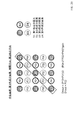
Images


Classifications
-
- G—PHYSICS
- G06—COMPUTING OR CALCULATING; COUNTING
- G06T—IMAGE DATA PROCESSING OR GENERATION, IN GENERAL
- G06T3/00—Geometric image transformations in the plane of the image
- G06T3/40—Scaling of whole images or parts thereof, e.g. expanding or contracting
- G06T3/4015—Image demosaicing, e.g. colour filter arrays [CFA] or Bayer patterns
-
- G—PHYSICS
- G06—COMPUTING OR CALCULATING; COUNTING
- G06T—IMAGE DATA PROCESSING OR GENERATION, IN GENERAL
- G06T3/00—Geometric image transformations in the plane of the image
- G06T3/40—Scaling of whole images or parts thereof, e.g. expanding or contracting
- G06T3/4007—Scaling of whole images or parts thereof, e.g. expanding or contracting based on interpolation, e.g. bilinear interpolation
-
- H—ELECTRICITY
- H04—ELECTRIC COMMUNICATION TECHNIQUE
- H04N—PICTORIAL COMMUNICATION, e.g. TELEVISION
- H04N23/00—Cameras or camera modules comprising electronic image sensors; Control thereof
- H04N23/80—Camera processing pipelines; Components thereof
- H04N23/84—Camera processing pipelines; Components thereof for processing colour signals
- H04N23/843—Demosaicing, e.g. interpolating colour pixel values
-
- H—ELECTRICITY
- H04—ELECTRIC COMMUNICATION TECHNIQUE
- H04N—PICTORIAL COMMUNICATION, e.g. TELEVISION
- H04N25/00—Circuitry of solid-state image sensors [SSIS]; Control thereof
- H04N25/10—Circuitry of solid-state image sensors [SSIS]; Control thereof for transforming different wavelengths into image signals
- H04N25/11—Arrangement of colour filter arrays [CFA]; Filter mosaics
- H04N25/13—Arrangement of colour filter arrays [CFA]; Filter mosaics characterised by the spectral characteristics of the filter elements
- H04N25/135—Arrangement of colour filter arrays [CFA]; Filter mosaics characterised by the spectral characteristics of the filter elements based on four or more different wavelength filter elements
-
- H—ELECTRICITY
- H04—ELECTRIC COMMUNICATION TECHNIQUE
- H04N—PICTORIAL COMMUNICATION, e.g. TELEVISION
- H04N2209/00—Details of colour television systems
- H04N2209/04—Picture signal generators
- H04N2209/041—Picture signal generators using solid-state devices
- H04N2209/042—Picture signal generators using solid-state devices having a single pick-up sensor
- H04N2209/045—Picture signal generators using solid-state devices having a single pick-up sensor using mosaic colour filter
- H04N2209/046—Colour interpolation to calculate the missing colour values
Definitions
- the present invention relates to signal processing executed by an imaging apparatus such as a digital camera.
- an imaging apparatus such as a digital camera.
- it relates to a pixel interpolation technique.
- an image sensor such as a CCD image sensor or a CMOS image sensor used in an image pickup apparatus such as a digital camera
- light received through a color filter is converted into an electric signal by photoelectric conversion and output as a pixel signal.
- the color filter include an RGB color filter and a YMCK color filter.
- a single-pixel image sensor outputs a pixel signal of one color for each pixel. For example, when an RGB color filter is used, a pixel signal of one of R (red), G (green), and B (blue) color components is output for one pixel.
- interpolation processing For pixel signals output from a single-plate color image sensor, it is necessary to obtain pixel signals of other color components by interpolation processing.
- Various algorithms are used for this interpolation processing. For example, a method of calculating a horizontal correlation degree and a vertical correlation degree and performing pixel interpolation using pixels in a direction with a high correlation degree is performed. Also, a method of performing pixel interpolation after weighting according to the distance between the target pixel and the surrounding pixels is performed.
- Patent Document 1 Japanese Patent Laid-Open No. 2006-186965
- a gray area and a color area in an image acquired by an image sensor with a Bayer array (RGB color filter) are discriminated, and the image area Pixel interpolation according to the characteristics is applied.
- a contrivance is made to suppress the generation of false colors in the region located at the boundary between the gray region and the color region.
- the correlation direction is determined using a gray image determination method for the correlation direction.
- pixel interpolation processing is performed using a pixel interpolation method for a color image area.
- the technique disclosed in Patent Document 1 can reduce the occurrence of false colors due to pixel interpolation processing.
- a color filter there is an imaging apparatus having a four-color filter such as a WRGB array, a Ye (yellow) -Cy (cyan) -G (green) -Mg (magenta) array, or an RGBYe array.
- a pixel signal of any one of four colors is output for one pixel.
- Patent Document 1 is based on the assumption that a Bayer array (RGB color filter) imaging device is used, and that the color filter array pattern (color information constituting the color filter) is known. For this reason, when the pattern of the color filter array (information on the color constituting the color filter) is unknown, it is difficult to apply the technique of Patent Document 1 as it is. Further, when the pattern of the color filter array (information on the colors constituting the color filter) is unknown, it is difficult to appropriately perform pixel interpolation processing.
- RGB color filter RGB color filter
- the present invention provides a pixel interpolation processing apparatus capable of appropriately performing pixel interpolation processing even when the pattern of the color filter array (information on the colors constituting the color filter) is unknown.
- An object is to realize an imaging device, a program, and an integrated circuit.
- a first color component filter is used at the beginning of the row, and the first color component filter and the second color component filter are alternately arranged.
- the image is acquired by an imaging unit having a four-color array filter in which the head of the third color component is the third color component filter and the third color component filter and the fourth color component filter are alternately arranged.
- a pixel interpolation processing device that performs pixel interpolation processing on an image to be processed includes a correlation value calculation unit, a correlation direction determination unit, and an interpolation unit.
- the correlation value calculation unit acquires a plurality of sets of correlation values in two directions orthogonal to each other on the image using pixel data of the peripheral region of the target pixel.
- the correlation direction determination unit determines the correlation direction in the peripheral region of the target pixel based on the correlation value acquired by the correlation value calculation unit.
- the interpolation unit performs pixel interpolation processing on the pixel of interest based on the correlation direction determined by the correlation direction determination unit.
- the interpolation unit performs the following processes (1) to (3) when it is determined that there is a direction with high correlation based on the correlation value.
- (1) When calculating a color component value of the same color as a pixel adjacent in the correlation direction of the target pixel, In the correlation direction, select the pixel values of two pixels adjacent to each other with the pixel of interest in between and the pixels of the same color arranged in the correlation direction including the pixel of interest, and calculate from the pixel values of the selected pixels Based on the correlation direction change rate, the color component value of the same color as that of the pixel adjacent to the target pixel in the correlation direction is calculated.
- a plurality of pixels of the same color are selected from a first pixel group that includes a first adjacent pixel that is one pixel adjacent in the normal direction of the target pixel and that is disposed in the correlation direction.
- a plurality of pixels of the same color are selected from the second pixel group that includes the second adjacent pixel that is the other pixel adjacent in the normal direction of the target pixel and that is disposed in the correlation direction.
- This pixel interpolation processing device can execute appropriate pixel interpolation processing even when the color filter array pattern (color information constituting the color filter) is unknown.
- the high-frequency component of the pixel signal in the direction orthogonal to the direction of high correlation (correlation direction) (normal direction of the correlation direction) has high correlation (similarity) regardless of the color of the color filter.
- the first to fourth color component pixel values are acquired for the pixel of interest, so what are the colors of the four colors (first to fourth colors) of the color filter? Even if it is unknown, the pixel interpolation process can be appropriately executed.
- a change rate for example, a Laplacian component
- the acquired change rate for example, a Laplacian component
- this pixel interpolation processing device based on the rate of change (for example, Laplacian component), the specific color component value of the pixel at the predetermined position acquired is used, and the direction with higher correlation (correlation direction)
- the pixel interpolation processing is executed by utilizing the fact that the high-frequency component of the pixel signal in the direction orthogonal to the correlation direction (normal direction of the correlation direction) has high (similar) correlation regardless of the color of the color filter. Compared to the above, it is possible to realize pixel interpolation processing with extremely high accuracy.
- this pixel interpolation processing device information on the color filter array pattern (information on the colors constituting the color filter) is unnecessary, so that the pixels are classified according to the color of the target pixel as in the prior art. There is no need to perform interpolation processing. Therefore, with this pixel interpolation processing device, highly accurate pixel interpolation processing can be realized with a small amount of calculation.
- 2nd invention is 1st invention, Comprising:
- region of an attention pixel is a pixel area which consists of 5 pixels x 5 pixels centering on pixel P22 which is an attention pixel,
- the first row consists of five pixels P00 to P04,
- the second row consists of five pixels P10 to P14,
- the third row consists of five pixels P20 to P24,
- the fourth row consists of five pixels P30 to P34,
- the fifth row is a pixel region composed of five pixels P40 to P44.
- pixel interpolation processing can be executed using a pixel area composed of 5 pixels ⁇ 5 pixels.
- the third invention is the second invention, and the interpolation section performs the following processes (1) to (3) when the correlation direction is the horizontal direction.
- the pixel value of the pixel Pxy is expressed as “Pxy”.
- D2out (P21 + P23) / 2 ⁇ (P20-2 ⁇ P22 + P24) ⁇ gain0 gain0:
- the color component value D2out is calculated by a process corresponding to the adjustment coefficient.
- the interpolation unit performs the following processes (1) to (3) when the correlation direction is the vertical direction.
- (1) When calculating the color component value D3out of the same color as a pixel adjacent in the correlation direction of the target pixel, the pixel value of the pixel Pxy is expressed as “Pxy”.
- D3out t0-t1 gain10:
- the color component value D3out is calculated by a process corresponding to the adjustment coefficient.
- the interpolation unit performs the following processes (1) to (3) when the correlation direction is the first diagonal direction which is the upper left diagonal direction.
- the pixel value of the pixel Pxy is expressed as “Pxy”.
- D4out (P11 + P33) / 2 ⁇ (P00-2 ⁇ P22 + P44) ⁇ gain40 gain40: The color component value D4out is calculated by a process corresponding to the adjustment coefficient.
- the pixel value of the pixel Pxy is expressed as “Pxy”.
- the color component value D3out is calculated by a process corresponding to the adjustment coefficient.
- the interpolation unit performs the following processes (1) to (3) when the correlation direction is the second diagonal direction which is the upper right diagonal direction.
- the pixel value of the pixel Pxy is expressed as “Pxy”.
- D4out (P13 + P31) / 2 ⁇ (P04-2 ⁇ P22 + P40) ⁇ gain50 gain50: The color component value D4out is calculated by a process corresponding to the adjustment coefficient.
- the pixel value of the pixel Pxy is expressed as “Pxy”.
- the color component value D3out is calculated by a process corresponding to the adjustment coefficient.
- Seventh to twelfth inventions are imaging devices each including an imaging unit and a pixel interpolation processing device according to the first to sixth inventions.
- the imaging unit includes the first color component filter at the top of the odd-numbered row, and the first color component filter and the second color component filter are alternately arranged.
- the third color component filter has a four-color arrangement filter in which the third color component filter and the fourth color component filter are alternately arranged, and acquires an image signal from the subject light.
- the pixel interpolation processing device performs pixel interpolation processing on an image signal.
- the first color component filter is used as the top of the row, and the first color component filters and the second color component filters are alternately arranged.
- Pixel interpolation is performed on an image acquired by an imaging unit having a four-color array filter in which the head is a third color component filter and the third color component filter and the fourth color component filter are alternately arranged.
- the pixel interpolation processing method includes a correlation value calculation step, a correlation direction determination step, and an interpolation step.
- the correlation value calculation step a plurality of sets of correlation values in two directions orthogonal to each other on the image are acquired using the pixel data of the peripheral region of the target pixel.
- the correlation direction determining step determines the correlation direction in the peripheral region of the target pixel based on the correlation value acquired by the correlation value calculating step.
- the interpolation step pixel interpolation processing is performed on the target pixel based on the correlation direction determined in the correlation direction determination step.
- the interpolation step performs the following processes (1) to (3) when it is determined that there is a direction with a high correlation based on the correlation value.
- (1) When calculating a color component value of the same color as a pixel adjacent in the correlation direction of the target pixel, In the correlation direction, select the pixel values of two pixels adjacent to each other with the pixel of interest in between and the pixels of the same color arranged in the correlation direction including the pixel of interest, and calculate from the pixel values of the selected pixels Based on the correlation direction change rate, the color component value of the same color as that of the pixel adjacent to the target pixel in the correlation direction is calculated.
- a plurality of pixels of the same color are selected from a first pixel group that includes a first adjacent pixel that is one pixel adjacent in the normal direction of the target pixel and that is disposed in the correlation direction.
- a plurality of pixels of the same color are selected from the second pixel group that includes the second adjacent pixel that is the other pixel adjacent in the normal direction of the target pixel and that is disposed in the correlation direction.
- the first color component filter is used as the first color component filter at the odd-numbered rows, and the first color component filters and the second color component filters are alternately arranged.
- Pixel interpolation is performed on an image acquired by an imaging unit having a four-color array filter in which the head is a third color component filter and the third color component filter and the fourth color component filter are alternately arranged.
- An integrated circuit that performs processing, and includes a correlation value calculation unit, a correlation direction determination unit, and an interpolation unit.
- the correlation value calculation unit acquires a plurality of sets of correlation values in two directions orthogonal to each other on the image using pixel data of the peripheral region of the target pixel.
- the correlation direction determination unit determines the correlation direction in the peripheral region of the target pixel based on the correlation value acquired by the correlation value calculation unit.
- the interpolation unit performs pixel interpolation processing on the pixel of interest based on the correlation direction determined by the correlation direction determination unit.
- the interpolation unit performs the following processes (1) to (3) when it is determined that there is a direction with high correlation based on the correlation value.
- (1) When calculating a color component value of the same color as a pixel adjacent in the correlation direction of the target pixel, In the correlation direction, select the pixel values of two pixels adjacent to each other with the pixel of interest in between and the pixels of the same color arranged in the correlation direction including the pixel of interest, and calculate from the pixel values of the selected pixels Based on the correlation direction change rate, the color component value of the same color as that of the pixel adjacent to the target pixel in the correlation direction is calculated.
- a plurality of pixels of the same color are selected from a first pixel group that includes a first adjacent pixel that is one pixel adjacent in the normal direction of the target pixel and that is disposed in the correlation direction.
- a plurality of pixels of the same color are selected from the second pixel group that includes the second adjacent pixel that is the other pixel adjacent in the normal direction of the target pixel and that is disposed in the correlation direction.
- a pixel interpolation processing device an imaging device, and a program capable of appropriately performing pixel interpolation processing even when a color filter array pattern (information on colors constituting the color filter) is unknown And an integrated circuit can be realized.
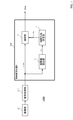
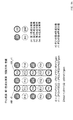
- FIG. 1 is a schematic configuration diagram of an imaging apparatus 1000 according to a first embodiment.
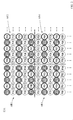
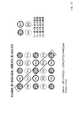
- An example of an array pattern of a first component color filter, a second component color filter, a third component color filter, and a fourth component color filter in an arbitrary four-color array color filter C11 installed in the imaging unit C1 is shown.
- Figure. The figure for demonstrating the calculation process of the vertical direction correlation value Cv.
- FIG. 5 is a relationship diagram for determining a correlation direction from determination correlation values Cv and Ch.
- FIG. 5 is a relationship diagram for determining a correlation direction from determination correlation values Cv and Ch.
- FIG. 5 is a relationship diagram for determining a correlation direction from determination correlation values Cd1 and Cd2.
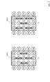
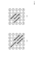
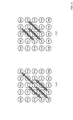
- region of 5 pixels x 5 pixels in case a center pixel (attention pixel) is a 1st color pixel and a correlation direction is a horizontal direction.
- region of 5 pixels x 5 pixels in case a center pixel (attention pixel) is a 1st color pixel and a correlation direction is a horizontal direction.
- region of 5 pixels x 5 pixels in case a center pixel (attention pixel) is a 1st color pixel and a correlation direction is a horizontal direction.
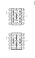
- region of 5 pixels x 5 pixels in case a center pixel (attention pixel) is a 1st color pixel and a correlation direction is a vertical direction.
- region of 5 pixels x 5 pixels in case a center pixel (attention pixel) is a 1st color pixel and a correlation direction is a vertical direction.
- region of 5 pixels x 5 pixels in case a center pixel (attention pixel) is a 1st color pixel and a correlation direction is a vertical direction.
- region of 5 pixels x 5 pixels in case a center pixel (attention pixel) is a 1st color pixel and a correlation direction is a vertical direction.
- region of 5 pixels x 5 pixels in case a center pixel (attention pixel) is a 1st color pixel and a correlation direction is a 1st diagonal direction.
- region of 5 pixels x 5 pixels in case a center pixel (attention pixel) is a 1st color pixel and a correlation direction is a 1st diagonal direction.
- region of 5 pixels x 5 pixels in case a center pixel (attention pixel) is a 1st color pixel and a correlation direction is a 1st diagonal direction.
- region of 5 pixels x 5 pixels in case a center pixel (attention pixel) is a 1st color pixel and a correlation direction is a 2nd diagonal direction.
- region of 5 pixels x 5 pixels in case a center pixel (attention pixel) is a 1st color pixel and a correlation direction is a 2nd diagonal direction.
- region of 5 pixels x 5 pixels in case a center pixel (attention pixel) is a 1st color pixel and a correlation direction is a 2nd diagonal direction.
- FIG. 1 is a schematic configuration diagram of an imaging apparatus 1000 according to the first embodiment.
- the imaging apparatus 1000 includes an imaging unit C1 that acquires subject light as an image signal by photoelectric conversion, and a signal processing unit C2 that performs predetermined signal processing on the image signal acquired by the imaging unit C1. And a pixel interpolation processing unit 100 (pixel interpolation processing device) that performs pixel interpolation processing on the image signal that has been subjected to predetermined signal processing by the signal processing unit C2.
- an imaging unit C1 that acquires subject light as an image signal by photoelectric conversion
- a signal processing unit C2 that performs predetermined signal processing on the image signal acquired by the imaging unit C1.
- a pixel interpolation processing unit 100 pixel interpolation processing device
- the imaging unit C1 includes an optical system, an arbitrary four-color array color filter, and an imaging element.
- the “arbitrary four-color array color filter” includes a first color component filter, a second color component filter, a third color component filter, and a fourth color component filter.
- the arrangement is as follows. That is, (1) In the first column, the first color filter, the second color filter, the first color filter, the second color filter,..., And the first color component filter and the second color component filter are alternately arranged.
- the third color filter, the fourth color filter, the third color filter, the fourth color filter,..., And the third color component filter and the fourth color component filter are alternately arranged.
- the first color component filter and the second color component filter are alternately arranged in the odd-numbered rows, and the third color component filter is arranged in the even-numbered rows. It is assumed that the fourth color component filters are alternately arranged.
- the “arbitrary four-color array color filter” will be described below as having such an array.
- the optical system is composed of one or a plurality of lenses, condenses subject light, and forms an image of the subject light on the image sensor surface.
- the optical system may have an exposure adjustment function, a focus adjustment function, and the like.
- the four-color array color filter includes four color component filters including a first color component color filter, a second color component color filter, a third color component color filter, and a fourth color component color filter. Has the sequence.
- the four-color array color filter is disposed on the image sensor surface of the image sensor.
- the image sensor has a plurality of pixels, and is condensed by an optical system and imaged on the surface of the image sensor through a four-color array color filter by photoelectric conversion into an image signal (electric signal). Convert to The imaging device acquires the first color component pixel signal in the first color component acquisition pixel, and acquires the second color component pixel signal in the second color component acquisition pixel. In addition, the imaging device acquires the third color component pixel signal in the third color component acquisition pixel, and acquires the fourth color component pixel signal in the fourth color component acquisition pixel. The imaging device uses the pixel signal (first color component pixel signal, second color component pixel signal, third color component pixel signal, and fourth color component pixel signal) acquired for each pixel as an image signal as a signal processing unit. Output to C2.
- the signal processing unit C2 inputs the image signal output from the imaging unit C1, and performs predetermined signal processing (for example, gain adjustment processing, white balance adjustment processing, gamma adjustment processing, etc.) on the input image signal. Do.
- the signal processing unit C2 outputs an image signal subjected to predetermined signal processing to the pixel interpolation processing unit 100 as an image signal D_raw.
- the pixel interpolation processing unit 100 includes a correlation value calculation unit 1, a correlation direction determination unit 2, and an interpolation unit 3, as shown in FIG.
- the correlation value calculation unit 1 inputs an image signal D_raw output from the signal processing unit C2 (a single image (one frame image) formed by the image signal D_raw is expressed as an image D_raw. The same applies hereinafter). .
- the correlation value calculation unit 1 calculates the following four correlation values for the pixel of interest (processing target pixel) on the image D_raw (details will be described later). (A1) Vertical correlation value Cv (A2) Horizontal correlation value Ch (A3) First diagonal direction correlation value Cd1 (A4) Second diagonal direction correlation value Cd2
- the correlation value calculation unit 1 outputs the four correlation values acquired for each pixel on the image D_raw to the correlation direction determination unit 2.
- the above four correlation values are collectively referred to as “Cx”.
- the correlation direction determination unit 2 inputs the correlation value Cx for each pixel output from the correlation value calculation unit 1.
- the correlation direction determination unit 2 determines the correlation direction for each pixel based on the correlation value Cx (details will be described later). Then, the correlation direction determination unit 2 outputs information Co_Dir regarding the correlation direction determined for each pixel to the interpolation unit 3.
- Interpolation unit 3 receives image signal D_raw output from signal processing unit C2 and information Co_Dir regarding the correlation direction determined for each pixel output from correlation direction determination unit 2. For each pixel of the image D_raw, the interpolation unit 3 includes all the pixels of the first color component, the second color component, the third color component, and the fourth color based on the correlation direction determined by the correlation direction determination unit 2. Pixel interpolation processing is performed so as to have color components (details will be described later). Then, the interpolation unit 3 converts the image signal after pixel interpolation processing (an image signal in which all pixels have the first color component, the second color component, the third color component, and the fourth color component) into the image signal Dout. As output.
- FIG. 2 shows an arrangement pattern of a first component color filter, a second component color filter, a third component color filter, and a fourth component color filter in an arbitrary four-color arrangement color filter C11 installed in the imaging unit C1. It is a figure which shows an example. As shown in FIG. 2, in the four-color array color filter, in the odd-numbered rows, the first component color filter, the second component color filter, the first component color filter, the second component color filter,. The first component color filters and the second component color filters are alternately arranged. In the even-numbered row, the third component color filter, the fourth component color filter, the third component color filter, the fourth component color filter,..., The third component color filter and the fourth component Color filters are arranged alternately.
- a description method of pixels of the four-color array color filter will be described.
- a pixel in a 5 ⁇ 5 matrix area is represented as an upper left area AR1 in FIG.
- the symbol P in the upper left area AR1 in FIG. 2 is a notation that does not consider which color component pixel the pixel is (the same applies to the areas AR2 to AR4 shown in FIG. 2).
- the symbol P may represent a pixel value.
- the symbol P11 represents the pixel itself of the first row and the first column and also represents the pixel value of the pixel of the first row and the first column.
- Light from the subject is collected by an optical system (not shown) of the image pickup unit C1, and passes through a four-color array color filter C11 arranged on the image pickup device surface to the image pickup device (not shown) of the image pickup unit C1.
- the four-color array color filter C11 is assumed to be the array pattern shown in FIG.
- the incident subject light is converted into an electrical signal (pixel signal) by photoelectric conversion for each pixel. That is, the first color component pixel value is acquired from the first color component pixel, the second color component pixel value is acquired from the second color component pixel, and the third color component pixel value is acquired from the third color component pixel.
- the fourth color component pixel value is acquired in the fourth color component pixel.
- the image signal acquired as described above (one pixel value of any one of the first color component pixel value, the second color component pixel value, the third color component pixel value, and the fourth color component pixel value for each pixel) Is output from the imaging unit C1 to the signal processing unit C2.
- predetermined signal processing for example, gain adjustment processing, white balance adjustment processing, gamma adjustment processing, etc.
- image signal D_raw image signal subjected to the predetermined signal processing is output to the correlation value calculation unit 1 and the interpolation unit 3 of the pixel interpolation processing unit 100.
- the correlation value calculation unit 1 calculates the correlation value Cx for each pixel from the image signal D_raw (image D_raw) output from the signal processing unit C2. This will be described in detail below.
- the correlation value calculation unit 1 calculates the following four correlation values for the target pixel (processing target pixel) on the image D_raw output from the signal processing unit C2.
- A1 Vertical correlation value Cv A2) Horizontal correlation value Ch
- A3) First diagonal direction correlation value Cd1 A4) Second diagonal direction correlation value Cd2
- the correlation value calculation processing (A1) to (A4) will be described below.
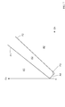
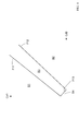
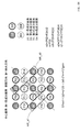
- FIG. 3 is a diagram for explaining the calculation process of the vertical direction correlation value Cv, and shows a 5 ⁇ 5 pixel matrix area centered on the center pixel P22. Note that the two pixels at the tip of the arrows in the figure indicate the target pixels for difference processing.
- the correlation value calculation unit 1 uses pixels P01 to P03, P11 to P13, P21 to P23, P31 to P33, and pixels of the same color adjacent in the vertical direction in the area AR41. An absolute value difference between values is calculated, and an average value (weighted average value) of the calculated absolute value differences is obtained. That is, the correlation value calculation unit 1 acquires a vertical direction correlation value Cv by performing processing corresponding to the following mathematical formula.
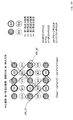
- FIG. 4 is a diagram for explaining the calculation process of the horizontal direction correlation value Ch, and shows a 5 ⁇ 5 pixel matrix area centered on the center pixel P22. Note that the two pixels at the tip of the arrows in the figure indicate the target pixels for difference processing.
- the correlation value calculation unit 1 calculates an absolute value difference of pixel values of pixels of the same color adjacent in the horizontal direction in an area AR51 including pixels P10 to P14, P20 to P24, and P30 to P34. Then, an average value (weighted average value) of the calculated absolute value differences is obtained. That is, the correlation value calculation unit 1 acquires a horizontal direction correlation value Ch by performing processing corresponding to the following mathematical formula.
- FIG. 5 is a diagram for explaining the calculation process of the first diagonal direction correlation value Cd1, and shows a 5 ⁇ 5 pixel matrix area centered on the center pixel P22. Note that the two pixels at the tip of the arrows in the figure indicate the target pixels for difference processing.
- abs (P11 ⁇ P33) is multiplied by a coefficient “2”. This is because weighting is performed according to the distance from the center pixel (distance on the image).
- the coefficient to be multiplied is not limited to the above, and may be another value.
- FIG. 6 is a diagram for explaining the calculation process of the second diagonal direction correlation value Cd2, and shows a 5 ⁇ 5 pixel matrix area centered on the center pixel P22. Note that the two pixels at the tip of the arrows in the figure indicate the target pixels for difference processing.
- abs (P13 ⁇ P31) is multiplied by a coefficient “2”. This is because weighting is performed according to the distance from the center pixel (distance on the image).
- the coefficient to be multiplied is not limited to the above, and may be another value.
- the four correlation values calculated by the correlation value calculation unit 1 are (A1) vertical direction correlation value Cv, (A2) horizontal direction correlation value Ch, (A3) first diagonal direction correlation value Cd1, and (A4)
- the second diagonal direction correlation value Cd2 is output to the correlation direction determination unit 2.
- the correlation direction determination unit 2 uses the correlation diagram of FIG. 7 or the correlation diagram of FIG. 8 for each pixel based on the correlation values Cv, Ch, Cd1, and Cd2 acquired by the correlation value calculation unit 1. To decide.
- FIG. 7 is a diagram showing the relationship between the correlation values Ch and Cv and the correlation direction determination areas A1 to A4.
- the horizontal axis (X axis) is the correlation value Ch
- the vertical axis (Y axis) is the correlation value Cv.
- the correlation direction determination areas A1 to A4 are determined by straight lines F1 to F3. That is, the correlation direction determination area A1 is an area surrounded by the Y axis and the straight line F1, and the correlation direction determination area A2 is an area surrounded by the X axis and the straight line F2, and the correlation direction determination area A3. Is a region surrounded by the straight line F1, the straight line F2, and the straight line F3, and the correlation direction determination region A4 is a region surrounded by the X axis, the Y axis, and the straight line F3.
- FIG. 8 is a diagram showing the relationship between the correlation values Cd1 and Cd2 and the correlation direction determination areas B1 to B4.
- the horizontal axis (X axis) is the correlation value Cd2
- the vertical axis (Y axis) is the correlation value Cd1.
- the correlation direction determination areas B1 to B4 are determined by straight lines F11 to F13. That is, the correlation direction determination area B1 is an area surrounded by the Y axis and the straight line F11, and the correlation direction determination area B2 is an area surrounded by the X axis and the straight line F12, and the correlation direction determination area B3. Is a region surrounded by the straight lines F11, F12, and F13, and the correlation direction determination region B4 is a region surrounded by the X axis, the Y axis, and the straight line F13.
- the correlation direction determination unit 2 uses the relationship diagram of FIG. 7 or the relationship diagram of FIG. 8 for each pixel based on the correlation values Cv, Ch, Cd1, and Cd2, according to the following (1) and (2). Determine the correlation direction.
- the correlation direction is determined using the relationship diagram of FIG.
- the correlation direction determination unit 2 determines the correlation direction of the target pixel as the “horizontal direction”.
- the correlation direction determination unit 2 determines the correlation direction of the target pixel as the “vertical direction”.
- the correlation direction determination unit 2 determines that “there is no correlation in any direction” for the pixel of interest.
- the correlation direction determination unit 2 determines the correlation direction of the target pixel as the “second oblique direction” (d2 direction). .
- the correlation direction determination unit 2 determines the correlation direction of the target pixel as the “first diagonal direction” (d1 direction). .
- the correlation direction determination unit 2 determines that “there is no correlation in any direction” for the pixel of interest.
- the correlation direction determination unit 2 determines that the correlation is high in the vertical and horizontal directions for the target pixel.
- the correlation direction determination result (information Co_Dir regarding the correlation direction) acquired for each pixel is output from the correlation direction determination unit 2 to the interpolation unit 3.
- relationship diagram is an example, and a relationship diagram having an area defined by another straight line may be used.
- the interpolation unit 3 performs pixel interpolation processing for the pixel of interest by a process corresponding to the following equation. Note that the pixel value of the first color component of the target pixel after pixel interpolation processing is D1out, the pixel value of the second color component is D2out, the pixel value of the third color component is D3out, and the pixel value of the fourth color component Is D4out.
- the target pixel is the first color component pixel.
- 9 to 12 are diagrams for explaining pixel interpolation processing when the target pixel is the first color component pixel and the correlation direction is the horizontal direction.
- the interpolation unit 3 performs the following processing to obtain the pixel value D1out of the first color component, the pixel value D2out of the second color component, the pixel value D3out of the third color component, Then, the pixel value D4out of the fourth color component is acquired.
- the interpolation unit 3 performs the following processing.
- the acquisition process (calculation process) of the pixel value D2out of the second color component will be described with reference to FIG.
- FIG. 9 is a diagram showing a 5 ⁇ 5 pixel matrix area in the case where the center pixel (target pixel) is the first color pixel.
- (Y20-2 ⁇ Y22 + Y24) is a horizontal Laplacian component (second-order differential component), and P22 is obtained by subtracting a value obtained by multiplying the average value of C21 and C23 by 1/4 of the Laplacian component.
- the second color component value C22 can be calculated.
- the pixel value D2out of the second color component can be acquired.
- the interpolation unit 3 adjusts the value of gain 0 and adjusts the Laplacian component to adjust the amount of high-frequency component of D 2 out.
- the interpolation unit 3 adjusts the value of gain 0 and adjusts the Laplacian component to adjust the amount of high-frequency component of D 2 out.
- the interpolation unit 3 adjusts the value of gain 0 and adjusts the Laplacian component to adjust the amount of high-frequency component of D 2 out.
- the interpolation unit 3 adjusts the value of gain 0 and adjusts the Laplacian component to adjust the amount of high-frequency component of D 2 out.
- the optical characteristics of the imaging unit C1 for example, characteristics of an optical filter or the like provided in the imaging unit C1
- the interpolation unit 3 performs the following process.
- the acquisition process (calculation process) of the pixel value D3out of the third color component will be described with reference to FIGS.
- FIGS. 10 and 11 are diagrams showing a matrix area of 5 pixels ⁇ 5 pixels when the central pixel (target pixel) is the first color pixel.
- the interpolating unit 3 uses the P01 to P41 included in the area AR_q0 shown in FIG. 10 to obtain the fourth color component value q0 of P21 by a process corresponding to the following equation.
- q0 (P11 + P31) / 2 ⁇ (P01-2 ⁇ P21 + P41) ⁇ gain1
- (P01-2 ⁇ P21 + P41) is a Laplacian component
- gain1 is a gain for adjusting a Laplacian component.
- the interpolation unit 3 uses the P03 to P43 included in the area AR_q1 shown in FIG. 10 to obtain the fourth color component value q1 of P23 by a process corresponding to the following equation.
- q1 (P13 + P33) / 2 ⁇ (P03-2 ⁇ P23 + P43) ⁇ gain2
- (P03-2 ⁇ P23 + P43) is a Laplacian component
- gain2 is a gain for adjusting a Laplacian component.
- the interpolation unit 3 calculates a value d0a obtained by estimating the difference in the fourth color component value between the pixel P11 and the pixel P21.
- d0a P11-q0 q0: Obtained as the fourth color component value of P21.
- the interpolation unit 3 calculates a value d0 obtained by estimating the difference in the fourth color component value between the pixel P12 and the pixel P22.
- d0 (d0a + d0b) / 2 Get as.
- high-frequency components of pixel signals in a direction (normal direction of the correlation direction) orthogonal to a direction with high correlation (correlation direction) are considered to have high correlation (similarity) regardless of the color of the color filter.
- the correlation direction is the horizontal direction
- the high-frequency component of the pixel signal in the vertical direction has a high correlation regardless of the color of the color filter.
- the interpolation unit 3 calculates a value d1a obtained by estimating a difference in the fourth color component value between the pixel P31 and the pixel P21.
- d1a P31-q0 q0: Obtained as the fourth color component value of P21.
- the interpolation unit 3 calculates a value d1 obtained by estimating the difference in the fourth color component value between the pixel P32 and the pixel P22.
- d1 (d1a + d1b) / 2 Get as.
- the correlation direction is the horizontal direction
- the high-frequency component of the pixel signal in the vertical direction has a high correlation regardless of the color of the color filter.
- the estimated value d1b of the difference between the values and (3) the estimated value d1 of the difference between the fourth color component values between the pixels P32 and P22 can be determined to have a high correlation.
- the interpolation unit 3 obtains (1) the value d0 obtained by estimating the difference in the fourth color component value between the pixel P12 and the pixel P22, and (2) the pixel P32 and the pixel P22, which are obtained by the above processing.
- the value d1 that estimates the difference in the fourth color component value between D3out (P12 + P32) / 2 ⁇ (d0 + d1) ⁇ gain3 gain3:
- the pixel value D3out of the third color component is acquired by the adjustment gain.
- the interpolation unit 3 performs the third based on the average value of the pixel values of P12 and P32 that are the third color component pixels and the high-frequency component in the direction (vertical direction) orthogonal to the correlation direction (horizontal direction). Obtain (estimate) the pixel value D3out of the color component. That is, the interpolation unit 3 indicates the change rate of the pixel signal in the direction (vertical direction) orthogonal to the correlation direction (horizontal direction) from the average value of the pixel values of P12 and P32 that are the third color component pixels (d0 + d1). ) ⁇ gain3 is subtracted to obtain (estimate) the pixel value D3out of the third color component with high accuracy.
- the interpolation unit 3 performs the following processing.
- the acquisition process (calculation process) of the pixel value D4out of the fourth color component will be described with reference to FIG.
- FIG. 12 is a diagram showing a matrix region of 5 pixels ⁇ 5 pixels in the case where the central pixel (target pixel) is the first color pixel.
- the interpolation unit 3 uses the P10 to P14 included in the area AR_r0 shown in FIG. 12 to obtain the fourth color component value r0 of P12 by a process corresponding to the following equation.
- r0 (P11 + P13) / 2 ⁇ (P10 ⁇ 2 ⁇ P12 + P14) ⁇ gain4
- (P10-2 ⁇ P12 + P14) is a Laplacian component
- gain4 is a gain for adjusting a Laplacian component.
- the interpolation unit 3 uses the P30 to P34 included in the area AR_r1 shown in FIG. 12 to obtain the fourth color component value r1 of P32 by a process corresponding to the following equation.
- r1 (P31 + P33) / 2 ⁇ (P30-2 ⁇ P32 + P34) ⁇ gain5
- (P30-2 ⁇ P32 + P34) is a Laplacian component
- gain5 is a gain for adjusting a Laplacian component.
- the interpolation unit 3 has been described in the calculation process of (1) the fourth color component value r0 of P12, (2) the fourth color component value r1 of P32, and the pixel value D3out of the third color component ( 3)
- a value d0 obtained by estimating the difference in the fourth color component value between the pixel P12 and the pixel P22, and (4) a value d1 obtained by estimating the difference in the fourth color component value between the pixel P32 and the pixel P22.
- D4out (r0 + r1) / 2 ⁇ (d0 + d1) ⁇ gain6 gain6:
- the pixel value D4out of the fourth color component is acquired by the adjustment gain.
- the interpolation unit 3 acquires (estimates) and acquires the fourth color component values r0 and r1 of the pixels P12 and P32 based on the Laplacian components calculated using the pixels in the upper and lower columns of the target pixel.
- the pixel value D4out of the fourth color component is acquired based on the average value of the fourth color component values r0 and r1 of the pixels P12 and P32 and the high frequency component in the direction (vertical direction) orthogonal to the correlation direction (horizontal direction). (presume.
- the interpolation unit 3 indicates the rate of change of the pixel signal in the direction (vertical direction) orthogonal to the correlation direction (horizontal direction) from the average value of the fourth color component values r0 and r1 of the pixels P12 and P32 (d0 + d1).
- the pixel value D4out of the fourth color component with high accuracy is acquired (estimated).
- the interpolation unit 3 performs pixel interpolation processing for the pixel of interest by processing corresponding to the following equation. Note that the pixel value of the first color component of the target pixel after pixel interpolation processing is D1out, the pixel value of the second color component is D2out, the pixel value of the third color component is D3out, and the pixel value of the fourth color component Is D4out.
- the target pixel is the first color component pixel.
- 13 to 16 are diagrams for explaining pixel interpolation processing when the target pixel is the first color component pixel and the correlation direction is the vertical direction.
- the interpolation unit 3 performs the following processing to obtain the pixel value D1out of the first color component, the pixel value D2out of the second color component, the pixel value D3out of the third color component, Then, the pixel value D4out of the fourth color component is acquired.
- the interpolation unit 3 performs the following process.
- the acquisition process (calculation process) of the pixel value D2out of the second color component will be described with reference to FIG.
- FIG. 13 is a diagram showing a matrix region of 5 pixels ⁇ 5 pixels in the case where the central pixel (target pixel) is the first color pixel.
- pixel interpolation with higher quality is possible. Processing can be performed.
- the interpolation unit 3 performs the following processing.
- the acquisition process (calculation process) of the pixel value D2out of the second color component will be described with reference to FIGS.
- 14 and 15 are diagrams showing a matrix region of 5 pixels ⁇ 5 pixels in the case where the central pixel (target pixel) is the first color pixel.
- the interpolation unit 3 uses the P10 to P14 included in the area AR_q0 shown in FIG. 14 to obtain the fourth color component value q0 of P12 by a process corresponding to the following equation.
- q0 (P11 + P13) / 2 ⁇ (P10 ⁇ 2 ⁇ P12 + P14) ⁇ gain11
- (P10 ⁇ 2 ⁇ P12 + P14) is a Laplacian component
- gain11 is a gain for adjusting a Laplacian component.
- the interpolation unit 3 uses the P30 to P34 included in the area AR_q1 shown in FIG. 14 to obtain the fourth color component value q1 of P32 by a process corresponding to the following equation.
- q1 (P31 + P33) / 2 ⁇ (P30-2 ⁇ P32 + P34) ⁇ gain12
- (P30-2 ⁇ P32 + P34) is a Laplacian component
- gain12 is a gain for adjusting a Laplacian component.
- high-frequency components of pixel signals in a direction (normal direction of the correlation direction) orthogonal to a direction with high correlation (correlation direction) are considered to have high correlation (similarity) regardless of the color of the color filter.
- the correlation direction is the vertical direction
- the high-frequency component of the pixel signal in the horizontal direction has a high correlation regardless of the color of the color filter.
- an estimated value d0a of a difference between the fourth color component values between the pixels P11 and P12 and (2) a fourth color component between the pixels P31 and P32 indicating a change in the horizontal direction (corresponding to a high frequency component). It can be determined that the estimated value d0b of the difference between the values and (3) the estimated value d0 of the difference between the fourth color component values between the pixels P21 and P22 have a high correlation.
- the interpolation unit 3 calculates a value d1 obtained by estimating the difference in the fourth color component value between the pixel P23 and the pixel P22.
- d1 (d1a + d1b) / 2 Get as.
- the correlation direction is the vertical direction
- the high-frequency component of the pixel signal in the horizontal direction has a high correlation regardless of the color of the color filter.
- the estimated value d1b of the difference between the values and (3) the estimated value d1 of the difference between the fourth color component values between the pixels P23 and P22 can be determined to have high correlation.
- the interpolation unit 3 obtains (1) the value d0 obtained by estimating the difference in the fourth color component value between the pixel P21 and the pixel P22, and (2) the pixel P23 and the pixel P22, which are obtained by the above processing.
- the value d1 that estimates the difference in the fourth color component value between D2out (P21 + P23) / 2 ⁇ (d0 + d1) ⁇ gain13 gain13:
- the pixel value D2out of the second color component is acquired by the adjustment gain.
- the interpolation unit 3 performs the second operation based on the average value of the pixel values of P21 and P23, which are the second color component pixels, and the high-frequency component in the direction (horizontal direction) orthogonal to the correlation direction (vertical direction). Obtain (estimate) the pixel value D2out of the color component. That is, the interpolation unit 3 indicates the change rate of the pixel signal in the direction (horizontal direction) orthogonal to the correlation direction (vertical direction) from the average value of the pixel values of P21 and P23 that are the second color component pixels (d0 + d1). ) ⁇ gain13 is subtracted to obtain (estimate) the pixel value D2out of the second color component with high accuracy.
- the interpolation unit 3 performs the following processing.
- the acquisition process (calculation process) of the pixel value D4out of the fourth color component will be described with reference to FIG.
- FIG. 16 is a diagram showing a matrix area of 5 pixels ⁇ 5 pixels in the case where the center pixel (target pixel) is the first color pixel.
- the interpolating unit 3 uses the P01 to P41 included in the area AR_r0 shown in FIG. 16 to obtain the fourth color component value r0 of P21 by a process corresponding to the following equation.
- r0 (P11 + P31) / 2 ⁇ (P01-2 ⁇ P21 + P41) ⁇ gain14
- (P01-2 ⁇ P21 + P41) is a Laplacian component
- gain14 is a gain for adjusting a Laplacian component.
- the interpolation unit 3 uses the P03 to P43 included in the area AR_r1 shown in FIG. 16 to obtain the fourth color component value r1 of P23 by a process corresponding to the following equation.
- r1 (P13 + P33) / 2 ⁇ (P03-2 ⁇ P23 + P43) ⁇ gain15
- (P03-2 ⁇ P23 + P43) is a Laplacian component
- gain15 is a gain for adjusting a Laplacian component.
- the interpolation unit 3 acquires (estimates) and acquires the fourth color component values r0 and r1 of the pixels P21 and P23 based on the Laplacian components calculated using the pixels in the left and right columns of the target pixel.
- the pixel value D4out of the fourth color component is acquired based on the average value of the fourth color component values r0 and r1 of the pixels P21 and P23 and the high frequency component in the direction (horizontal direction) orthogonal to the correlation direction (vertical direction). (presume.
- the interpolation unit 3 indicates the rate of change of the pixel signal in the direction (horizontal direction) orthogonal to the correlation direction (vertical direction) from the average value of the fourth color component values r0 and r1 of the pixels P21 and P23 (d0 + d1).
- ⁇ gain16 the pixel value D4out of the fourth color component with high accuracy is acquired (estimated).
- the interpolation unit 3 performs pixel interpolation processing on the target pixel by processing corresponding to the following equation.
- the target pixel is the first color component pixel.
- FIGS. 17 to 19 are diagrams for describing pixel interpolation processing when the target pixel is the first color component pixel and the correlation direction is the first diagonal direction.
- the interpolation unit 3 performs the following processing to obtain the pixel value D1out of the first color component, the pixel value D2out of the second color component, the pixel value D3out of the third color component, Then, the pixel value D4out of the fourth color component is acquired.
- the interpolation unit 3 performs the following processing.
- the acquisition process (calculation process) of the pixel value D4out of the fourth color component will be described with reference to FIG.
- FIG. 17 is a diagram showing a matrix area of 5 pixels ⁇ 5 pixels in the case where the center pixel (target pixel) is the first color component pixel.
- the interpolation unit 3 uses the five pixels P00, P11, P22, P33, and P44 to acquire the fourth color component value D4out of P22 by the following process.
- D4out (P11 + P33) / 2 ⁇ (P00-2 ⁇ P22 + P44) ⁇ gain40
- (P00-2 ⁇ P22 + P44) is a Laplacian component
- gain 40 is a gain for adjusting a Laplacian component.
- the interpolation unit 3 acquires the third color component value D3out of P22 by the following process.
- D3out (q0 + q1) / 2 ⁇ (s0 ⁇ 2 ⁇ s + s1) ⁇ gain41 Note that (s0-2 ⁇ s + s1) is a Laplacian component, and gain 41 is a gain for adjusting a Laplacian component.
- the interpolation unit 3 acquires (1) s0, s, s1, which are the same color component values (the first color component value in the above), obtained by using the fact that the correlation is high in the first oblique direction, (2)
- the third color component value D3out of P22 is acquired using q0 and q1, which are the same color component values (the third color component value in the above example). Accordingly, the interpolation unit 3 can acquire a highly accurate pixel interpolation value (third color component value D3out of P22) using the fact that the correlation is high in the first oblique direction.
- D2out (q0 + q1) / 2 ⁇ (s0 ⁇ 2 ⁇ s + s1) ⁇ gain42 Note that (s0-2 ⁇ s + s1) is a Laplacian component, and gain is a gain for adjusting a Laplacian component.
- the interpolation unit 3 acquires (1) s0, s, s1, which are the same color component values (the first color component value in the above), obtained by using the fact that the correlation is high in the first oblique direction, (2)
- the second color component value D2out of P22 is acquired using q0 and q1, which are the same color component values (the second color component value in the above example). Accordingly, the interpolation unit 3 can acquire a highly accurate pixel interpolation value (second color component value D2out of P22) using the fact that the correlation is high in the first oblique direction.
- the interpolation unit 3 performs pixel interpolation processing for the target pixel by a process corresponding to the following equation: Do.
- the target pixel is the first color component pixel.
- 20 to 22 are diagrams for explaining pixel interpolation processing when the target pixel is the first color component pixel and the correlation direction is the first diagonal direction.
- the interpolation unit 3 performs the following processing to obtain the pixel value D1out of the first color component, the pixel value D2out of the second color component, the pixel value D3out of the third color component, Then, the pixel value D4out of the fourth color component is acquired.
- the interpolation unit 3 sets the pixel value P22 of the target pixel as the pixel value D1out of the first color component.
- the interpolation unit 3 performs the following processing.
- the acquisition process (calculation process) of the pixel value D4out of the fourth color component will be described with reference to FIG.
- FIG. 20 is a diagram showing a matrix area of 5 pixels ⁇ 5 pixels in the case where the center pixel (target pixel) is the first color component pixel.
- the interpolation unit 3 uses the five pixels P04, P13, P22, P31, and P40 to acquire the fourth color component value D4out of P22 by the following process.
- D4out (P13 + P31) / 2 ⁇ (P04-2 ⁇ P22 + P40) ⁇ gain50
- (P04-2 ⁇ P22 + P40) is a Laplacian component
- gain50 is a gain for adjusting a Laplacian component.
- the interpolation unit 3 acquires the third color component value D3out of P22 by the following process.
- D3out (q0 + q1) / 2 ⁇ (s0 ⁇ 2 ⁇ s + s1) ⁇ gain51 Note that (s0-2 ⁇ s + s1) is a Laplacian component, and gain 51 is a gain for adjusting a Laplacian component.
- the interpolation unit 3 acquires (1) s0, s, s1, which are the same color component values (the first color component value in the above), obtained by using the fact that the correlation is high in the second oblique direction, (2)
- the third color component value D3out of P22 is acquired using q0 and q1, which are the same color component values (the third color component value in the above example).
- the interpolation unit 3 can acquire a highly accurate pixel interpolation value (third color component value D3out of P22) using the fact that the correlation is high in the second oblique direction.
- D2out (q0 + q1) / 2 ⁇ (s0 ⁇ 2 ⁇ s + s1) ⁇ gain52 Note that (s0-2 ⁇ s + s1) is a Laplacian component, and gain 52 is a gain for adjusting a Laplacian component.
- the interpolation unit 3 acquires (1) s0, s, s1, which are the same color component values (the first color component value in the above), obtained by using the fact that the correlation is high in the second oblique direction, (2)
- the second color component value D2out of P22 is acquired using q0 and q1, which are the same color component values (the second color component value in the above example).
- the interpolation unit 3 can acquire a highly accurate pixel interpolation value (second color component value D2out of P22) using the fact that the correlation is high in the second oblique direction.
- the interpolation unit 3 performs pixel interpolation processing on the pixel of interest by a process corresponding to the following equation. Note that the pixel value of the first color component of the target pixel after pixel interpolation processing is D1out, the pixel value of the second color component is D2out, the pixel value of the third color component is D3out, and the pixel value of the fourth color component Is D4out.
- the target pixel is the first color component pixel.
- the interpolation unit 3 acquires D1out, D2out, D3out, and D4out by processing corresponding to the following mathematical formula.
- D1out P22
- D2out medium (P21, P23, (P01 + P03 + P21 + P23) / 4, (P21 + P23 + P41 + P43) / 4)
- D3out medium (P12, P32, (P10 + P30 + P12 + P32) / 4, (P12 + P32 + P14 + P34) / 4)
- D4out medium (P11, P13, P31, P33)
- Medium () is a function for acquiring a median value.
- medium () takes the average value of the two central values when the number of elements is an even number.
- the median interpolation process can be executed by processing in the same manner as described above.
- the interpolation unit 3 performs pixel interpolation processing on the pixel of interest by processing corresponding to the following equation.
- the interpolation unit 3 acquires D1out, D2out, D3out, and D4out by processing corresponding to the following mathematical formula.
- D3out (P12 + P32) / 2
- D4out (P11 + P13 + P31 + P33) / 4
- the average value interpolation process for the color image region can be executed by performing the same process as described above.
- the interpolation unit 3 acquires D1out, D2out, D3out, and D4out for each pixel. Then, an image formed by the acquired D1out, D2out, D3out, D4out (four color component values for each pixel (first color component value, second color component value, third color component value, fourth color component value). ) Is output from the interpolation unit 3.
- the pixel interpolation processing unit 100 executes appropriate pixel interpolation processing even when the pattern of the color filter array (information on the colors constituting the color filter) is unknown.
- the high-frequency component of the pixel signal in the direction (normal direction of the correlation direction) orthogonal to the direction with high correlation (correlation direction) is correlated regardless of the color of the color filter. Since the first to fourth color component pixel values are acquired for the pixel of interest using the fact that the color is high (similar), what color is the four colors (first color to fourth color) of the color filter? Even if it is unknown whether or not the pixel interpolation processing is performed, the pixel interpolation processing can be appropriately executed.
- the pixel interpolation processing unit 100 of the imaging apparatus 1000 acquires a Laplacian component from the color filter array pattern using pixels of the same color, and uses the acquired Laplacian component to specify a pixel at a predetermined position. Since the color component value is estimated, the specific color component value of the pixel at a predetermined position is appropriately estimated even when the pattern of the color filter array (information on the color constituting the color filter) is unknown ( Acquisition).
- the pixel interpolation processing unit 100 of the imaging apparatus 1000 uses the specific color component value of the pixel obtained at the predetermined position based on the Laplacian component as described above, and is orthogonal to the direction with high correlation (correlation direction). Since pixel interpolation processing is performed using the fact that the high-frequency component of the pixel signal in the direction (normal direction of the correlation direction) has a high correlation (similarity) regardless of the color of the color filter, the pixel interpolation processing is executed. Thus, it is possible to realize pixel interpolation processing with extremely high accuracy.
- the pixel interpolation processing unit 100 of the imaging apparatus 1000 Since the pixel interpolation processing unit 100 of the imaging apparatus 1000 does not need information on the color filter array pattern (information on the colors constituting the color filter), it is classified according to the color of the pixel of interest as in the prior art. Thus, there is no need to perform pixel interpolation processing. Therefore, the pixel interpolation processing unit 100 of the imaging apparatus 1000 can realize highly accurate pixel interpolation processing with a small amount of calculation.
- a part or all of the imaging device of the above embodiment may be realized as an integrated circuit (for example, an LSI, a system LSI, or the like).
- Part or all of the processing of each functional block in the above embodiment may be realized by a program.
- a part or all of the processing of each functional block in the above embodiment is performed by a central processing unit (CPU) in the computer.
- a program for performing each processing is stored in a storage device such as a hard disk or a ROM, and is read out and executed in the ROM or the RAM.
- each process of the above embodiment may be realized by hardware, or may be realized by software (including a case where it is realized together with an OS (operating system), middleware, or a predetermined library). Further, it may be realized by mixed processing of software and hardware. Needless to say, when the imaging apparatus according to the above-described embodiment is realized by hardware, it is necessary to perform timing adjustment for performing each process. In the above embodiment, for convenience of explanation, details of timing adjustment of various signals generated in actual hardware design are omitted.
- execution order of the processing methods in the above embodiment is not necessarily limited to the description of the above embodiment, and the execution order can be changed without departing from the gist of the invention.
- a computer program that causes a computer to execute the above-described method and a computer-readable recording medium that records the program are included in the scope of the present invention.
- the computer-readable recording medium include a flexible disk, hard disk, CD-ROM, MO, DVD, DVD-ROM, DVD-RAM, large-capacity DVD, next-generation DVD, and semiconductor memory. .
- the computer program is not limited to the one recorded on the recording medium, but may be transmitted via a telecommunication line, a wireless or wired communication line, a network represented by the Internet, or the like.
- circuit may be realized in whole or in part by hardware, software, or a mixture of hardware and software.
- Imaging Device 1000 Imaging Device C1 Imaging Unit C2 Signal Processing Unit 100 Pixel Interpolation Processing Unit (Pixel Interpolation Processing Device) DESCRIPTION OF SYMBOLS 1 Correlation value calculation part 2 Correlation direction determination part 3 Interpolation part
Landscapes
- Engineering & Computer Science (AREA)
- Physics & Mathematics (AREA)
- Multimedia (AREA)
- Signal Processing (AREA)
- General Physics & Mathematics (AREA)
- Theoretical Computer Science (AREA)
- Spectroscopy & Molecular Physics (AREA)
- Color Television Image Signal Generators (AREA)
- Image Processing (AREA)
- Television Systems (AREA)
- Facsimile Image Signal Circuits (AREA)
- Color Image Communication Systems (AREA)
Priority Applications (1)
| Application Number | Priority Date | Filing Date | Title |
|---|---|---|---|
| US15/171,953 US9679358B2 (en) | 2013-12-20 | 2016-06-02 | Pixel interpolation processing apparatus, imaging apparatus, interpolation processing method, and integrated circuit |
Applications Claiming Priority (2)
| Application Number | Priority Date | Filing Date | Title |
|---|---|---|---|
| JP2013-264371 | 2013-12-20 | ||
| JP2013264371A JP6276580B2 (ja) | 2013-12-20 | 2013-12-20 | 画素補間処理装置、撮像装置、プログラムおよび集積回路 |
Related Child Applications (1)
| Application Number | Title | Priority Date | Filing Date |
|---|---|---|---|
| US15/171,953 Continuation US9679358B2 (en) | 2013-12-20 | 2016-06-02 | Pixel interpolation processing apparatus, imaging apparatus, interpolation processing method, and integrated circuit |
Publications (1)
| Publication Number | Publication Date |
|---|---|
| WO2015093253A1 true WO2015093253A1 (ja) | 2015-06-25 |
Family
ID=53402606
Family Applications (1)
| Application Number | Title | Priority Date | Filing Date |
|---|---|---|---|
| PCT/JP2014/081473 Ceased WO2015093253A1 (ja) | 2013-12-20 | 2014-11-27 | 画素補間処理装置、撮像装置、プログラムおよび集積回路 |
Country Status (3)
| Country | Link |
|---|---|
| US (1) | US9679358B2 (enExample) |
| JP (1) | JP6276580B2 (enExample) |
| WO (1) | WO2015093253A1 (enExample) |
Cited By (1)
| Publication number | Priority date | Publication date | Assignee | Title |
|---|---|---|---|---|
| CN113781350A (zh) * | 2021-09-16 | 2021-12-10 | Oppo广东移动通信有限公司 | 图像处理方法、图像处理装置、电子设备及存储介质 |
Families Citing this family (4)
| Publication number | Priority date | Publication date | Assignee | Title |
|---|---|---|---|---|
| JP6598507B2 (ja) * | 2015-05-11 | 2019-10-30 | キヤノン株式会社 | 撮像装置、撮像システム、信号処理方法 |
| CN108769635B (zh) * | 2018-05-30 | 2020-01-21 | Oppo(重庆)智能科技有限公司 | 拍摄装置、电子设备及图像获取方法 |
| CN109658333A (zh) * | 2018-11-14 | 2019-04-19 | 深圳市华星光电半导体显示技术有限公司 | 图像放大插值的方法、图像放大插值装置以及显示装置 |
| JP2023010159A (ja) * | 2021-07-09 | 2023-01-20 | 株式会社ソシオネクスト | 画像処理装置および画像処理方法 |
Citations (4)
| Publication number | Priority date | Publication date | Assignee | Title |
|---|---|---|---|---|
| JP2009290607A (ja) * | 2008-05-29 | 2009-12-10 | Hoya Corp | 撮像装置 |
| JP2010103736A (ja) * | 2008-10-23 | 2010-05-06 | Mega Chips Corp | 画像拡大方法 |
| JP2011055038A (ja) * | 2009-08-31 | 2011-03-17 | Sony Corp | 画像処理装置、および画像処理方法、並びにプログラム |
| JP2012191465A (ja) * | 2011-03-11 | 2012-10-04 | Sony Corp | 画像処理装置、および画像処理方法、並びにプログラム |
Family Cites Families (15)
| Publication number | Priority date | Publication date | Assignee | Title |
|---|---|---|---|---|
| JP2002064831A (ja) * | 2000-08-15 | 2002-02-28 | Sanyo Electric Co Ltd | 単板式カラーカメラの色分離回路 |
| JP4358055B2 (ja) * | 2004-07-21 | 2009-11-04 | 株式会社東芝 | 補間画素生成回路 |
| JP4333997B2 (ja) * | 2004-08-24 | 2009-09-16 | シャープ株式会社 | 画像処理装置、撮影装置、画像処理方法、画像処理プログラムおよび記録媒体 |
| JP4428195B2 (ja) * | 2004-10-22 | 2010-03-10 | 株式会社日立製作所 | 撮像装置、補完信号生成方法及びプログラム |
| JP5049460B2 (ja) * | 2004-11-09 | 2012-10-17 | イーストマン コダック カンパニー | カラー撮像画像データの補間方法およびプログラム |
| JP4840740B2 (ja) | 2004-12-01 | 2011-12-21 | 株式会社メガチップス | 画素補間方法および画像判定方法 |
| US7551214B2 (en) * | 2005-12-01 | 2009-06-23 | Megachips Lsi Solutions Inc. | Pixel interpolation method |
| JP5017597B2 (ja) * | 2007-11-27 | 2012-09-05 | 株式会社メガチップス | 画素補間方法 |
| JP5068158B2 (ja) * | 2007-12-28 | 2012-11-07 | イーストマン コダック カンパニー | 撮像装置 |
| WO2012114574A1 (ja) * | 2011-02-21 | 2012-08-30 | 三菱電機株式会社 | 画像拡大装置及び方法 |
| BR112012027309A2 (pt) * | 2011-02-28 | 2016-08-02 | Fujifilm Corp | aparelho de geração de imagens coloridas |
| JP5981824B2 (ja) * | 2012-09-28 | 2016-08-31 | 株式会社メガチップス | 画素補間処理装置、撮像装置、プログラムおよび集積回路 |
| JP6012375B2 (ja) * | 2012-09-28 | 2016-10-25 | 株式会社メガチップス | 画素補間処理装置、撮像装置、プログラムおよび集積回路 |
| CN105264886B (zh) * | 2013-05-23 | 2017-05-03 | 富士胶片株式会社 | 像素插值装置及其动作控制方法 |
| JP6276569B2 (ja) * | 2013-12-02 | 2018-02-07 | 株式会社メガチップス | 画素補間処理装置、撮像装置、プログラムおよび集積回路 |
-
2013
- 2013-12-20 JP JP2013264371A patent/JP6276580B2/ja not_active Expired - Fee Related
-
2014
- 2014-11-27 WO PCT/JP2014/081473 patent/WO2015093253A1/ja not_active Ceased
-
2016
- 2016-06-02 US US15/171,953 patent/US9679358B2/en active Active
Patent Citations (4)
| Publication number | Priority date | Publication date | Assignee | Title |
|---|---|---|---|---|
| JP2009290607A (ja) * | 2008-05-29 | 2009-12-10 | Hoya Corp | 撮像装置 |
| JP2010103736A (ja) * | 2008-10-23 | 2010-05-06 | Mega Chips Corp | 画像拡大方法 |
| JP2011055038A (ja) * | 2009-08-31 | 2011-03-17 | Sony Corp | 画像処理装置、および画像処理方法、並びにプログラム |
| JP2012191465A (ja) * | 2011-03-11 | 2012-10-04 | Sony Corp | 画像処理装置、および画像処理方法、並びにプログラム |
Cited By (2)
| Publication number | Priority date | Publication date | Assignee | Title |
|---|---|---|---|---|
| CN113781350A (zh) * | 2021-09-16 | 2021-12-10 | Oppo广东移动通信有限公司 | 图像处理方法、图像处理装置、电子设备及存储介质 |
| CN113781350B (zh) * | 2021-09-16 | 2023-11-24 | Oppo广东移动通信有限公司 | 图像处理方法、图像处理装置、电子设备及存储介质 |
Also Published As
| Publication number | Publication date |
|---|---|
| US20160284055A1 (en) | 2016-09-29 |
| JP2015122576A (ja) | 2015-07-02 |
| US9679358B2 (en) | 2017-06-13 |
| JP6276580B2 (ja) | 2018-02-07 |
Similar Documents
| Publication | Publication Date | Title |
|---|---|---|
| US9225948B2 (en) | Pixel interpolation apparatus, imaging apparatus, pixel interpolation processing method, integrated circuit, and non-transitory computer readable storage medium | |
| JP5872408B2 (ja) | カラー撮像装置及び画像処理方法 | |
| JP4162111B2 (ja) | 画像処理方法および装置並びに記録媒体 | |
| US7551214B2 (en) | Pixel interpolation method | |
| JP5872407B2 (ja) | カラー撮像装置及び画像処理方法 | |
| JP6276569B2 (ja) | 画素補間処理装置、撮像装置、プログラムおよび集積回路 | |
| JP6239358B2 (ja) | 画素補間装置、撮像装置、プログラムおよび集積回路 | |
| JP2005159957A (ja) | 色補間方法 | |
| JP3771054B2 (ja) | 画像処理装置及び画像処理方法 | |
| WO2011152174A1 (ja) | 画像処理装置、および画像処理方法、並びにプログラム | |
| JP6276580B2 (ja) | 画素補間処理装置、撮像装置、プログラムおよび集積回路 | |
| JP2008070853A (ja) | 画像配列データの補償方法 | |
| JP2007259401A (ja) | ノイズ低減装置ならびにその制御方法およびその制御プログラムならびに撮像装置およびディジタル・カメラ | |
| JP4717371B2 (ja) | 画像処理装置および画像処理プログラム | |
| JP3905708B2 (ja) | 画像補間装置 | |
| KR101327790B1 (ko) | 영상 보간 방법 및 장치 | |
| JP5981824B2 (ja) | 画素補間処理装置、撮像装置、プログラムおよび集積回路 | |
| JP6276581B2 (ja) | 画素補間処理装置、撮像装置、プログラムおよび集積回路 | |
| KR20190036253A (ko) | 그라디언트 기반 rgbw cfa 디모자킹 장치 및 방법 | |
| JPWO2018179378A1 (ja) | 画像処理装置、画像処理システム、画像処理方法、及びプログラム | |
| JP6559020B2 (ja) | 画像処理装置、画像処理方法、及びプログラム | |
| JP4006913B2 (ja) | 単板式固体撮像素子の色補間方法および単板式固体撮像素子の色補間処理プログラムを記録した記録媒体 | |
| JP4334151B2 (ja) | 画像補間装置 | |
| JP4334152B2 (ja) | 画像補間装置 | |
| JP4666786B2 (ja) | 画像補間装置 |
Legal Events
| Date | Code | Title | Description |
|---|---|---|---|
| 121 | Ep: the epo has been informed by wipo that ep was designated in this application |
Ref document number: 14871025 Country of ref document: EP Kind code of ref document: A1 |
|
| NENP | Non-entry into the national phase |
Ref country code: DE |
|
| 122 | Ep: pct application non-entry in european phase |
Ref document number: 14871025 Country of ref document: EP Kind code of ref document: A1 |