US9225948B2 - Pixel interpolation apparatus, imaging apparatus, pixel interpolation processing method, integrated circuit, and non-transitory computer readable storage medium - Google Patents
Pixel interpolation apparatus, imaging apparatus, pixel interpolation processing method, integrated circuit, and non-transitory computer readable storage medium Download PDFInfo
- Publication number
- US9225948B2 US9225948B2 US14/427,835 US201314427835A US9225948B2 US 9225948 B2 US9225948 B2 US 9225948B2 US 201314427835 A US201314427835 A US 201314427835A US 9225948 B2 US9225948 B2 US 9225948B2
- Authority
- US
- United States
- Prior art keywords
- pixel
- color
- component
- value
- interpolation
- Prior art date
- Legal status (The legal status is an assumption and is not a legal conclusion. Google has not performed a legal analysis and makes no representation as to the accuracy of the status listed.)
- Active
Links
Images


Classifications
-
- H04N9/045—
-
- H—ELECTRICITY
- H04—ELECTRIC COMMUNICATION TECHNIQUE
- H04N—PICTORIAL COMMUNICATION, e.g. TELEVISION
- H04N25/00—Circuitry of solid-state image sensors [SSIS]; Control thereof
- H04N25/10—Circuitry of solid-state image sensors [SSIS]; Control thereof for transforming different wavelengths into image signals
- H04N25/11—Arrangement of colour filter arrays [CFA]; Filter mosaics
- H04N25/13—Arrangement of colour filter arrays [CFA]; Filter mosaics characterised by the spectral characteristics of the filter elements
- H04N25/133—Arrangement of colour filter arrays [CFA]; Filter mosaics characterised by the spectral characteristics of the filter elements including elements passing panchromatic light, e.g. filters passing white light
-
- H—ELECTRICITY
- H04—ELECTRIC COMMUNICATION TECHNIQUE
- H04N—PICTORIAL COMMUNICATION, e.g. TELEVISION
- H04N23/00—Cameras or camera modules comprising electronic image sensors; Control thereof
- H04N23/80—Camera processing pipelines; Components thereof
- H04N23/84—Camera processing pipelines; Components thereof for processing colour signals
- H04N23/843—Demosaicing, e.g. interpolating colour pixel values
-
- G—PHYSICS
- G06—COMPUTING; CALCULATING OR COUNTING
- G06T—IMAGE DATA PROCESSING OR GENERATION, IN GENERAL
- G06T3/00—Geometric image transformation in the plane of the image
- G06T3/40—Scaling the whole image or part thereof
- G06T3/4007—Interpolation-based scaling, e.g. bilinear interpolation
-
- H—ELECTRICITY
- H04—ELECTRIC COMMUNICATION TECHNIQUE
- H04N—PICTORIAL COMMUNICATION, e.g. TELEVISION
- H04N25/00—Circuitry of solid-state image sensors [SSIS]; Control thereof
- H04N25/10—Circuitry of solid-state image sensors [SSIS]; Control thereof for transforming different wavelengths into image signals
- H04N25/11—Arrangement of colour filter arrays [CFA]; Filter mosaics
- H04N25/13—Arrangement of colour filter arrays [CFA]; Filter mosaics characterised by the spectral characteristics of the filter elements
- H04N25/135—Arrangement of colour filter arrays [CFA]; Filter mosaics characterised by the spectral characteristics of the filter elements based on four or more different wavelength filter elements
Definitions
- the present invention relates to signal processing performed by an imaging apparatus such as a digital camera, and more particularly, to a pixel interpolation technique.
- Image sensors such as charge-coupled device (CCD) image sensors or complementary metal oxide semiconductor (CMOS) image sensors, incorporated in imaging apparatuses including digital cameras convert light received through color filters to electrical signals by photoelectric conversion, and output the electrical signals as pixel signals.
- color filters include RGB color filters or YMCK color filters.
- a single-chip image sensor outputs a pixel signal of one color for one pixel.
- the image sensor outputs a pixel signal representing one of red (R), green (G), and blue (B) color components for one pixel.
- Each pixel signal output from the single-chip color image sensor needs interpolation to generate pixel signals representing the other color components.
- Such interpolation may be performed using various algorithms. For example, one interpolation method calculates the degree of correlation in the horizontal direction and the degree of correlation in the vertical direction, and uses a pixel located in the direction with a higher correlation to perform pixel interpolation.
- Another interpolation method may perform weighting in accordance with the distance between a target pixel and its neighboring pixel before such pixel interpolation.
- a technique described in Patent Literature 1 differentiates a gray area and a color area in an image obtained by an image sensor with a Bayer array (RGB color filters), and performs pixel interpolation in accordance with the characteristics of the image areas.
- the technique in Patent Literature 1 reduces false colors in an area of boundary between a gray area and a color area.
- the technique in Patent Literature 1 determines the direction of correlation with a method intended for a grayscale image area, and performs pixel interpolation with an interpolation method intended for a color image area, thus reducing false colors caused by pixel interpolation.
- Patent Literature 1 Japanese Unexamined Patent Publication No. 2006-186965
- An imaging apparatus may include four color filters, such as a WRGB array of color filters.
- An imaging apparatus including a single-chip image sensor with the WRGB array of color filters outputs a pixel signal representing one of white (W), red (R), green (G), and blue (B) components for one pixel.
- Patent Literature 1 should be used for an image sensor with a Bayer array (RGB color filters), and is not directly applicable to a single-chip image sensor with a different pattern of color filters, such as a WRGB array.
- RGB color filters RGB color filters
- a first aspect of the invention provides a pixel interpolation apparatus that performs pixel interpolation processing on an image obtained by an imaging unit.
- the imaging unit has color filters of four different colors arranged in a predetermined pattern, and includes at least white component pixels.
- the pixel interpolation apparatus includes a color saturation evaluation value obtaining unit, a correlation degree obtaining unit, a pixel interpolation method determination unit, an interpolation unit, and a color space conversion unit.
- the color saturation evaluation value obtaining unit evaluates color saturation of a predetermined image area of the image, and obtains a color saturation evaluation value for the image area.
- the correlation degree obtaining unit obtains degrees of correlation for a plurality of pairs in two directions orthogonal to each other in the image using pixel data for an area around a target pixel.
- the pixel interpolation method determination unit determines a pixel interpolation method for the target pixel based on the color saturation evaluation value obtained by the color saturation evaluation value obtaining unit and the degree of correlation obtained by the correlation degree obtaining unit.
- the interpolation unit performs pixel interpolation processing on the image with the pixel interpolation method determined by the pixel interpolation method determination unit, and obtains image data in a predetermined color space defining at least a white component value.
- the color space conversion unit in the image data in the color space obtained by the interpolation unit, (1) uses a white component signal of a pixel obtained by the interpolation unit as a luminance signal and obtains a color difference signal by using the luminance signal, and a first color component signal and a second color component signal that are other than the white component signal of the pixel obtained by the interpolation unit when the target pixel is a white component pixel or when a white component signal of the target pixel is obtained through interpolation processing performed using a white component pixel around the target pixel, and (2) generates a luminance signal from a first color component signal, a second color component signal, and a third color component signal that are other than a white component signal of a pixel obtained by the interpolation unit, and obtains a color difference signal using the luminance signal, and the first color component signal and the second color component signal for the pixel obtained by the interpolation unit when the target pixel is not a white component pixel and a white component signal of the target pixel is
- This pixel interpolation apparatus calculates the degrees of correlation for a plurality of pairs in two directions orthogonal to each other in an image signal (Raw image) obtained by a single-chip imaging unit (image sensor) having four color filters in the WRGB array in one example using pixel data for an area around a target pixel, and performs pixel interpolation processing by using the calculated degree of correlation as a criterion for determination.
- the pixel interpolation processing apparatus then selectively uses a luminance signal generated from a first component signal (e.g., an R-component signal), a second component signal (e.g., a G-component signal), and a third component signal (e.g., a B-component signal), and a luminance signal generated from a W-component signal to perform pixel interpolation processing with higher accuracy and obtain a color difference signal (e.g., a YCbCr signal) with higher accuracy.
- a first component signal e.g., an R-component signal
- a second component signal e.g., a G-component signal
- a third component signal e.g., a B-component signal
- This pixel interpolation apparatus calculates a color saturation evaluation value for an area around a target pixel, and selects a correlation determination method and a pixel interpolation method based on the color saturation evaluation value.
- This pixel interpolation apparatus performs the process for calculating a color saturation evaluation value optimum for an array of four color pixels including a W-pixel, (e.g., the WRGB array or the WYMC array (Y: yellow, M: magenta, C: cyan)) to prevent erroneous determination of the correlation direction and erroneous interpolation.
- the pixel interpolation apparatus thus reduces false colors occurring in the pixel interpolation processing.
- the pixel interpolation apparatus can perform appropriate pixel interpolation processing on an image signal obtained by a single-chip image sensor having four color filters such as a WRGB color filter array.
- a second aspect of the invention provides the pixel interpolation apparatus of the first aspect of the invention in which the color filters are in a WRGB array, the predetermined color space is a WRGB color space, the first color component signal is a red component signal, the second color component signal is a blue component signal, and the third color component signal is a green component signal.
- This pixel interpolation apparatus calculates the degrees of correlation for a plurality of pairs in two directions orthogonal to each other in an image signal (Raw image) obtained by a single-chip imaging unit (image sensor) having four color filters in, for example, the WRGB array, using pixel data for an area around a target pixel, and performs pixel interpolation processing by using the calculated degree of correlation as a criterion for determination.
- Raw image image signal obtained by a single-chip imaging unit (image sensor) having four color filters in, for example, the WRGB array
- the pixel interpolation processing apparatus then selectively uses a luminance signal generated from a first component signal (e.g., an R-component signal), a second component signal (e.g., a G-component signal), and a third component signal (e.g., a B-component signal), and a luminance signal generated from a W-component signal to perform pixel interpolation processing with higher accuracy and obtain a color difference signal (e.g., a YCbCr signal) with higher accuracy.
- a first component signal e.g., an R-component signal
- a second component signal e.g., a G-component signal
- a third component signal e.g., a B-component signal
- This pixel interpolation apparatus calculates a color saturation evaluation value for an area around a target pixel, and selects a correlation determination method and a pixel interpolation method based on the color saturation evaluation value.
- This pixel interpolation apparatus performs the process for calculating a color saturation evaluation value optimum for a WRGB array to prevent erroneous determination of the correlation direction and erroneous interpolation. The pixel interpolation apparatus thus reduces false colors occurring in the pixel interpolation processing.
- the pixel interpolation apparatus can perform appropriate pixel interpolation processing on an image signal obtained by a single-chip image sensor having four color filters such as a WRGB color filter array.
- a third aspect of the invention provides the pixel interpolation apparatus of the second aspect of the invention in which the correlation degree obtaining unit obtains degrees of correlation in a horizontal direction, a vertical direction, a first diagonal direction, and a second diagonal direction orthogonal to the first diagonal direction in the image.
- This pixel interpolation apparatus performs the pixel interpolation processing using the degree of correlation in the horizontal direction, the vertical direction, the first diagonal direction, and the second diagonal direction orthogonal to the first diagonal direction in the image.
- the first diagonal direction preferably forms an angle of 45 degrees with the horizontal direction or the vertical direction.
- a fourth aspect of the invention provides the pixel interpolation apparatus of one of the first to third aspects of the invention in which the color saturation evaluation value obtaining unit evaluates color saturation of an image area of 5 ⁇ 5 pixels including a central target pixel, and obtains a color saturation evaluation value for the image area.
- the correlation degree obtaining unit obtains the degree of correlation in the image area of 5 ⁇ 5 pixels including the central target pixel.
- This pixel interpolation apparatus can evaluate the color saturation and obtain the degree of correlation by using an image area of 5 ⁇ 5 pixels.
- the use of the image area of 5 ⁇ 5 pixels allows processing to be performed in four patterns in total in which the target pixel is one of the four color components W, R, G, and B.
- a fifth aspect of the invention provides the pixel interpolation apparatus of one of the first to fourth aspects of the invention in which the interpolation unit interpolates a pixel value with the first color component of the target pixel by subtracting a Laplacian component value calculated from pixel values of a plurality of pixels with the second color component arranged in a correlation direction having a high degree of correlation determined by the pixel interpolation method determination unit from an average of pixel values of two pixels with the first color component that are adjacent across the target pixel in the correlation direction.
- This pixel interpolation apparatus performs pixel interpolation processing that responds to changes in the correlation direction in units of pixels.
- the pixel interpolation apparatus can thus perform pixel interpolation processing with higher accuracy.
- the first color component is one of the W, R, G, and B components.
- the second color component is a color component other than the first color component.
- the second color component may not be one of the W, R, G, and B components or may be another color component (e.g., a W ⁇ R-component, a B+G-component, a W ⁇ G-component, or a W ⁇ B-component).
- a sixth aspect of the invention provides the pixel interpolation apparatus of the fifth aspect of the invention in which the interpolation unit interpolates the pixel value with the first color component of the target pixel by subjecting the Laplacian component value to gain adjustment, and subtracting the Laplacian component value that has undergone the gain adjustment from the average of the pixel values of the two pixels with the first color component that are adjacent across the target pixel.
- This pixel interpolation apparatus performs pixel interpolation processing by adjusting the Laplacian component value, and can thus adjust the Laplacian component value in accordance with the optical characteristics of the imaging unit (e.g., the optical characteristics of the image sensor or the optical filters) to perform pixel interpolation processing with a higher quality.
- the optical characteristics of the imaging unit e.g., the optical characteristics of the image sensor or the optical filters
- a seventh aspect of the invention includes an imaging unit and the pixel interpolation apparatus of one of the first to sixth aspects of the invention.
- the imaging unit has color filters of four different colors arranged in a predetermined pattern and includes at least white component pixels.
- the imaging unit obtains an image signal from subject light.
- An eighth aspect of the invention provides a program enabling a computer to implement a pixel interpolation processing method for performing pixel interpolation on an image obtained by an imaging unit.
- the imaging unit has color filters of four different colors arranged in a predetermined pattern and includes at least white component pixels.
- the pixel interpolation processing method includes a color saturation evaluation value obtaining process, a correlation degree obtaining process, a pixel interpolation method determination process, an interpolation process, and a color space conversion process.
- the color saturation evaluation value obtaining process evaluates color saturation of a predetermined image area of the image, and obtains a color saturation evaluation value for the image area.
- the correlation degree obtaining process obtains degrees of correlation for a plurality of pairs in two directions orthogonal to each other in the image using pixel data for an area around a target pixel.
- the pixel interpolation method determination process determines a pixel interpolation method for the target pixel based on the color saturation evaluation value obtained by the color saturation evaluation value obtaining process and the degree of correlation obtained by the correlation degree obtaining process.
- the interpolation process performs pixel interpolation processing on the image with the pixel interpolation method determined by the pixel interpolation method determination process, and obtains image data in a predetermined color space defining at least a white component value.
- the color space conversion process in the image data in the color space obtained by the interpolation process, (1) uses a white component signal of a pixel obtained by the interpolation process as a luminance signal and obtains a color difference signal by using the luminance signal, and a first color component signal and a second color component signal that are other than the white component signal of the pixel obtained by the interpolation process when the target pixel is a white component pixel or when a white component signal of the target pixel is obtained through interpolation processing performed using a white component pixel around the target pixel, and (2) generates a luminance signal from a first color component signal, a second color component signal, and a third color component signal that are other than a white component signal of a pixel obtained by the interpolation process, and obtains a color difference signal using the luminance signal, and the first color component signal and the second color component signal for the pixel obtained by the interpolation process when the target pixel is not a white component pixel and a white component signal of the target pixel is
- the program has the same advantageous effects as the pixel interpolation apparatus of the first aspect of the present invention.
- a ninth aspect of the invention provides an integrated circuit that performs pixel interpolation processing on an image obtained by an imaging unit.
- the imaging unit has color filters of four different colors arranged in a predetermined pattern and includes at least white component pixels.
- the integrated circuit includes a color saturation evaluation value obtaining unit, a correlation degree obtaining unit, a pixel interpolation method determination unit, an interpolation unit, and a color space conversion unit.
- the color saturation evaluation value obtaining unit evaluates color saturation of a predetermined image area of the image, and obtains a color saturation evaluation value for the image area.
- the correlation degree obtaining unit obtains degrees of correlation for a plurality of pairs in two directions orthogonal to each other in the image using pixel data for an area around a target pixel.
- the pixel interpolation method determination unit determines a pixel interpolation method for the target pixel based on the color saturation evaluation value obtained by the color saturation evaluation value obtaining unit and the degree of correlation obtained by the correlation degree obtaining unit.
- the interpolation unit performs pixel interpolation processing on the image with the pixel interpolation method determined by the pixel interpolation method determination unit, and obtains image data in a predetermined color space defining at least a white component value.
- the color space conversion unit in the color space obtained by the interpolation unit, (1) uses a white component signal of a pixel obtained by the interpolation unit as a luminance signal and obtains a color difference signal by using the luminance signal, and a first color component signal and a second color component signal that are other than the white component signal of the pixel obtained by the interpolation unit when the target pixel is a white component pixel or when a white component signal of the target pixel is obtained through interpolation processing performed using a white component pixel around the target pixel in the image data, and (2) generates a luminance signal from a first color component signal, a second color component signal, and a third color component signal that are other than a white component signal of a pixel obtained by the interpolation unit, and obtains a color difference signal using the luminance signal, and the first color component signal and the second color component signal for the pixel obtained by the interpolation unit when the target pixel is not a white component pixel and a white component signal of the target pixel is
- the integrated circuit has the same advantageous effects as the pixel interpolation apparatus of the first aspect of the present invention.
- the pixel interpolation apparatus, the imaging apparatus, the program, and the integrated circuit of the present invention allow appropriate pixel interpolation processing on an image signal obtained by a single-chip image sensor having four color filters such as a WRGB color filter array.
- FIG. 1A is a schematic diagram of an imaging apparatus 1000 according to a first embodiment.
- FIG. 1B is a schematic diagram of a color space conversion unit 35 according to the first embodiment.
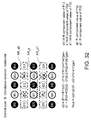
- FIG. 2 is a diagram describing pixels in a WRGB array.
- FIG. 3 shows a matrix area of 5 ⁇ 5 pixels.
- FIG. 4 shows a matrix area of 5 ⁇ 5 pixels.
- FIG. 5 shows a matrix area of 5 ⁇ 5 pixels
- FIG. 6 is a diagram describing a process for obtaining an evaluation value in a vertical direction.
- FIG. 7 is a diagram describing a process for obtaining an evaluation value in a horizontal direction.
- FIG. 8 is a diagram describing a process for obtaining an evaluation value in a first diagonal direction.
- FIG. 9 is a diagram describing a process for obtaining an evaluation value in a second diagonal direction.
- FIG. 10 is a diagram showing the relationship between a color saturation evaluation value L and a color saturation evaluation coefficient KL.
- FIG. 11 is a diagram describing a process for calculating a vertical direction correlation value Cv_color intended for a color image area.
- FIG. 12 is a diagram describing a process for calculating a horizontal direction correlation value Ch_color intended for a color image area.
- FIG. 13 is a diagram describing a process for calculating a first diagonal direction correlation value Cd 1 _color intended for a color image area.
- FIG. 14 is a diagram describing a process for calculating a second diagonal direction correlation value Cd 2 _color intended for a color image area.
- FIG. 15 is a diagram describing a process for calculating a vertical direction correlation value Cv_gray intended for a grayscale image area.
- FIG. 16 is a diagram describing a process for calculating a horizontal direction correlation value Ch_gray intended for a grayscale image area.
- FIG. 17 is a diagram describing a process for calculating a first diagonal direction correlation value Cd 1 _gray intended for a grayscale image area.
- FIG. 18 is a diagram describing a process for calculating a second diagonal direction correlation value Cd 2 _gray intended for a grayscale image area.
- FIG. 19 shows combinations of correlation determination methods and pixel interpolation methods to be selected based on the relationship between a color saturation evaluation coefficient KL and thresholds TH 1 and TH 2 .
- FIG. 20 is a flowchart of a method for calculating correlation values Cv and Ch used for determination.
- FIG. 21 is a flowchart of a method for calculating correlation values Cd 1 and Cd 2 used for determination.
- FIG. 22 is a relationship diagram determining the direction of correlation based on the correlation values Cv and Ch used for determination.
- FIG. 23 is a relationship diagram determining the direction of correlation based on the correlation values Cd 1 and Cd 2 used for determination.
- FIG. 24 is a diagram describing pixel interpolation in the horizontal direction (for a color image area) for an image area including a G-pixel in the center.
- FIG. 25 is a diagram describing pixel interpolation in the horizontal direction (for a color image area) for an image area including a G-pixel in the center.
- FIG. 26 is a diagram describing pixel interpolation in the horizontal direction (for a color image area) for an image area including a G-pixel in the center.
- FIG. 27 is a diagram describing pixel interpolation in the horizontal direction (for a color image area) for an image area including an R-pixel in the center.
- FIG. 28 is a diagram describing pixel interpolation in the horizontal direction (for a color image area) for an image area including an R-pixel in the center.
- FIG. 29 is a diagram describing pixel interpolation in the horizontal direction (for a color image area) for an image area including an R-pixel in the center.
- FIG. 30 is a diagram describing pixel interpolation in the horizontal direction (for a color image area) for an image area including a B-pixel in the center.
- FIG. 31 is a diagram describing pixel interpolation in the horizontal direction (for a color image area) for an image area including a B-pixel in the center.
- FIG. 32 is a diagram describing pixel interpolation in the horizontal direction (for a color image area) for an image area including a B-pixel in the center.
- FIG. 33 is a diagram describing pixel interpolation in the horizontal direction (for a color image area) for an image area including a W-pixel in the center.
- FIG. 34 is a diagram describing pixel interpolation in the horizontal direction (for a color image area) for an image area including a W-pixel in the center.
- FIG. 35 is a diagram describing pixel interpolation in the horizontal direction (for a color image area) for an image area including a W-pixel in the center.
- FIG. 36 is a diagram describing pixel interpolation in the vertical direction (for a color image area) for an image area including a G-pixel in the center.
- FIG. 37 is a diagram describing pixel interpolation in the vertical direction (for a color image area) for an image area including a G-pixel in the center.
- FIG. 38 is a diagram describing pixel interpolation in the vertical direction (for a color image area) for an image area including a G-pixel in the center.
- FIG. 39 is a diagram describing pixel interpolation in the first diagonal direction (for a color image area) for an image area including a G-pixel in the center.
- FIG. 40 is a diagram describing pixel interpolation in the first diagonal direction (for a color image area) for an image area including a G-pixel in the center.
- FIG. 41 is a diagram describing pixel interpolation in the first diagonal direction (for a color image area) for an image area including a G-pixel in the center.
- FIG. 42 is a diagram describing pixel interpolation in the second diagonal direction (for a color image area) for an image area including a G-pixel in the center.
- FIG. 43 is a diagram describing pixel interpolation in the second diagonal direction (for a color image area) for an image area including a G-pixel in the center.
- FIG. 44 is a diagram describing pixel interpolation in the second diagonal direction (for a color image area) for an image area including a G-pixel in the center.
- FIG. 1A is a schematic diagram of an imaging apparatus 1000 according to a first embodiment.
- the imaging apparatus 1000 includes an imaging unit 1 , a signal processing unit 2 , and a pixel interpolation processing unit 3 .
- the imaging unit 1 converts light from a subject through photoelectric conversion to obtain image signals.
- the signal processing unit 2 performs predetermined signal processing on the image signals obtained by the imaging unit 1 .
- the pixel interpolation processing unit 3 performs pixel interpolation processing on the image signals that have undergone the predetermined signal processing performed by the signal processing unit 2 .
- the imaging unit 1 includes an optical system, a WRGB color filter array, and an image sensor.
- the optical system including one or more lenses, collects light from a subject, and focuses the subject light onto the surface of the image sensor.
- the optical system may be capable of exposure adjustment and focus adjustment.
- the WRGB array of color filters includes four color filters, or the color filters for a W-component, an R-component, a G-component, and a B-component.
- the WRGB array has a predetermined pattern.
- the color filters in the WRGB array are arranged on the imaging surface of the image sensor.
- the W-component color filter may be a colorless transparent filter, or may be no filter.
- a pixel located under the W-component filter only needs a pixel signal for the W-component, which is a luminance signal. Thus, no filter may be arranged above such a pixel that needs a pixel signal for the W-component.
- the image sensor has a plurality of pixels.
- the image sensor converts subject light, which has been collected by the optical system and focused onto the imaging surface through the WRGB array of color filters, by photoelectric conversion to generate image signals (electrical signals).
- the image sensor generates a W-component pixel signal through a pixel for obtaining a W-component, and generates an R-component pixel signal through a pixel for obtaining an R-component.
- the image sensor also generates a G-component pixel signal through a pixel for obtaining a G-component, and generates a B-component pixel signal through a pixel for obtaining a B-component.
- the image sensor outputs the pixel signals generated through those pixels (the W-component pixel signal, R-component pixel signal, G-component pixel signal, and B-component pixel signal) to the signal processing unit 2 as image signals.
- the signal processing unit 2 receives the image signals output from the imaging unit 1 , and subjects the input image signals to predetermined signal processing (e.g., gain adjustment, white balance adjustment, and gamma correction).
- the signal processing unit 2 outputs the image signals that have undergone the predetermined signal processing to the pixel interpolation processing unit 3 as image signals D_raw.
- the pixel interpolation processing unit 3 includes a color saturation evaluation value calculation unit 31 , a correlation value calculation unit 32 , a pixel interpolation method determination unit 33 , an interpolation unit 34 , and a color space conversion unit 35 .
- the color saturation evaluation value calculation unit 31 receives an image signal D_raw output from the signal processing unit 2 (a single image, or a one-frame image formed using the image signal D_raw, hereafter expressed as an image D_raw).
- the color saturation evaluation value calculation unit 31 calculates a color saturation evaluation value L for a target pixel (processing target pixel) in the image D_raw, and further normalizes the color saturation evaluation value L using a predetermined function to obtain a color saturation evaluation coefficient KL (0 ⁇ KL ⁇ 1) (described in detail later).
- the color saturation evaluation value calculation unit 31 then outputs the color saturation evaluation coefficient KL obtained for each pixel included in the image D_raw to the pixel interpolation method determination unit 33 .
- the correlation value calculation unit 32 receives an image signal D_raw output from the signal processing unit 2 .
- the correlation value calculation unit 32 calculates the eight correlation values below (described in detail later):
- the correlation value calculation unit 32 outputs the eight correlation values calculated for each pixel in the image D_raw to the pixel interpolation method determination unit 33 .
- the pixel interpolation method determination unit 33 receives the color saturation evaluation coefficient KL for each pixel output from the color saturation evaluation value calculation unit 31 and the correlation values for each pixel output from the correlation value calculation unit 32 .
- the pixel interpolation method determination unit 33 determines the correlation direction and the pixel interpolation method for each pixel based on the color saturation evaluation coefficient KL and the correlation values (described in detail later).
- the pixel interpolation method determination unit 33 outputs information about the correlation direction and the pixel interpolation method determined for each pixel to the interpolation unit 34 .
- the pixel interpolation method determination unit 33 outputs information about the correlation direction determined for each pixel to the color space conversion unit 35 .
- the interpolation unit 34 receives the image signals D_raw output from the signal processing unit 2 and information about the correlation direction and the pixel interpolation method determined for each pixel output from the pixel interpolation method determination unit 33 .
- the interpolation unit 34 performs pixel interpolation processing for each pixel in the image D_raw to allow each of all the pixels to have the W-component, the R-component, the G-component, and the B-component using the correlation direction and the pixel interpolation method determined by the pixel interpolation method determination unit 33 (described in detail later).
- the interpolation unit 34 outputs image signals resulting from the pixel interpolation processing (image signals in which each of all the pixels included an image formed by the image signals has the W-component, the R-component, the G-component, and the B-component) to the color space conversion unit 35 as image signals D 1 .
- the color space conversion unit 35 receives the image signals D 1 output from the interpolation unit 34 and information about the correlation direction output from the pixel interpolation method determination unit 33 .
- the color space conversion unit 35 converts the image signals D 1 , which are signals in the WRGB color space, to signals in the YCbCr color space.
- the color space conversion unit 35 outputs the image signals resulting from the color space conversion as image signals Dout.
- the color space conversion unit 35 includes a luminance signal obtaining unit 351 , a selection signal generation unit 352 , a luminance signal output unit 353 , subtracters 354 and 356 , and gain adjustment units 355 and 357 .
- the luminance signal obtaining unit 351 receives an R-component signal, a G-component signal, and a B-component signal output from the interpolation unit 34 .
- the luminance signal obtaining unit 351 obtains a luminance signal Y 0 by using the input R-component signal, G-component signal, and B-component signal, and outputs the luminance signal Y 0 to the luminance signal output unit 353 .
- the selection signal generation unit 352 receives information about the correlation direction for each pixel output from the pixel interpolation method determination unit 33 , and generates a selection signal based on the correlation direction.
- the selection signal generation unit 352 outputs the generated selection signal to the luminance signal output unit 353 .
- the luminance signal output unit 353 receives the luminance signal Y 0 output from the luminance signal obtaining unit 351 and the W-color component signal W output from the interpolation unit 34 , and the selection signal output from the selection signal generation unit 352 .
- the luminance signal output unit 353 generates a luminance signal Yout using the luminance signal Y 0 and the W-color component signal W in accordance with the selection signal, and outputs the luminance signal Yout.
- the gain adjustment unit 355 subjects the B ⁇ Y signal output from the subtracter 354 to predetermined gain adjustment to obtain a Cb signal, and outputs the obtained Cb signal.
- the gain adjustment unit 357 subjects the R-Y signal output from the subtracter 356 to predetermine gain adjustment to obtain a Cr signal, and outputs the obtained Cr signal.
- the imaging apparatus 1000 with the above structure will now be described.
- FIG. 2 shows an example of an array pattern of W-component color filters, R-component color filters, G-component color filters, and B-component color filters included in the WRGB color filter array 11 .
- the WRGB color filter array includes one row in which green filters and red filters are arranged alternately in the order of G, R, G, R, . . . , and the next row in which blue filters and white filters (or no filters) are arranged alternately in the order of B, W, B, W, . . . .
- FIG. 3( a ) shows a matrix area of 5 ⁇ 5 pixels.
- P represents a pixel without showing its color component W, R, G, or B.
- FIG. 3( b ) shows each pixel labeled with its color component.
- R represents a pixel with a red component
- G represents a pixel with a green component
- B represents a pixel with a blue component
- W represents a pixel with a white component.
- FIG. 3( b ) shows a matrix area of pixel array consisting of 25 pixels P00 to P44 including a target pixel P22, in which the central pixel P22 (G 22 ) is a green component pixel (corresponding to an area AR 1 consisting of 5 ⁇ 5 pixels in FIG. 2) .
- the other figures also show the pixel arrays in the same manner as described above.
- the symbols P, W, R, G, and B in the embodiment and in the formulae therein may each represent the pixel value.
- P11 represents the pixel at the first row and the first column, and also indicates the pixel value of the pixel at the first row and the first column.
- the WRGB color filter array 11 has the array pattern shown in FIG. 2 .
- the image sensor in the imaging unit 1 converts the entering subject light for each pixel into an electrical signal (pixel signal) through photoelectric conversion. More specifically, the image sensor obtains a W-component pixel value at a W-component pixel, an R-component pixel value at an R-component pixel, a G-component pixel value at a G-component pixel, and a B-component pixel value at a B-component pixel.
- the image signal obtained through the above processing (image signal in which each pixel included in an image formed by the image signal has one of the W-component pixel value, the R-component pixel value, the G-component pixel value, and the B-component pixel value) is output from the imaging unit 1 to the signal processing unit 2 .
- the signal processing unit 2 subjects the image signal obtained by the imaging unit 1 to predetermined signal processing (e.g., gain adjustment, white balance adjustment, and gamma correction).
- predetermined signal processing e.g., gain adjustment, white balance adjustment, and gamma correction.
- the image signal (image signal D_raw) resulting from the predetermined signal processing is output to the color saturation evaluation value calculation unit 31 , the correlation value calculation unit 32 , and the interpolation unit 34 included in the pixel interpolation processing unit 3 .
- the color saturation evaluation value calculation unit 31 calculates a color saturation evaluation value for each pixel based on the image signal D_raw (image D_raw) output from the signal processing unit 2 , and normalizes the color saturation evaluation value L using a predetermined function to obtain a color saturation evaluation coefficient KL (0 ⁇ KL ⁇ 1). This process will now be described in detail below.
- the color saturation evaluation value calculation unit 31 sets an image area of 5 ⁇ 5 pixels including a target pixel as the center (hereafter referred to as a matrix area) in the input image D_raw.
- the color saturation evaluation value calculation unit 31 analyzes the distribution of color components in the set matrix area to calculate the color saturation evaluation value for the matrix area (the color saturation evaluation value for the target pixel).
- the color saturation evaluation value calculation unit 31 calculates six evaluation values (1) to (6) below for the matrix area including the target pixel, and sets the smallest one of the six evaluation values as the color saturation evaluation value L.
- the color saturation evaluation value calculation unit 31 classifies the matrix area into four patterns. More specifically, the color saturation evaluation value calculation unit 31 classifies the matrix area into the four patterns: a matrix area in which the central pixel is a green component pixel (hereafter, a G-pixel), a matrix area in which the central pixel is a red component pixel (hereafter, an R-pixel), and a matrix area in which the central pixel is a blue component pixel (hereafter, a B-pixel), and a matrix area in which the central pixel is a white component pixel (hereafter, a W-pixel).
- a matrix area in which the central pixel is a green component pixel (hereafter, a G-pixel)
- a matrix area in which the central pixel is a red component pixel hereafter, an R-pixel
- a blue component pixel hereafter, a blue component pixel
- W-pixel white component pixel
- FIG. 4( a ) shows a matrix area in which the central pixel is a G-pixel.
- FIG. 4( b ) shows a matrix area in which the central pixel is an R-pixel.
- FIG. 5( a ) is a matrix area in which the central pixel is a B-pixel.
- FIG. 5( b ) is a matrix area in which the central pixel is a W-pixel.
- the color saturation evaluation value calculation unit 31 calculates an average Wave of the pixel values of W-pixels, an average Gave of the pixel values of G-pixels, an average Rave of the pixel values of R-pixels, and an average Bave of the pixel values of B-pixels in an area of 3 ⁇ 3 pixels including the central pixel through the processing corresponding to the formulae below.
- W ave ( W 11+ W 13+ W 31+ W 33)/4
- G ave G 22
- R ave ( R 21+ R 23)/2
- B ave ( B 12+ B 32)/2
- the color saturation evaluation value calculation unit 31 calculates the average color component difference evaluation value diff_ave_color through the processing corresponding to the formula below.
- diff_ave_color abs( G ave ⁇ R ave)+abs( G ave ⁇ B ave)
- abs(x) is a function that returns the absolute value of x.
- the color saturation evaluation value calculation unit 31 calculates an average Wave of the pixel values of W-pixels, an average Gave of the pixel values of G-pixels, an average Rave of the pixel values of R-pixels, and an average Bave of the pixel values of B-pixels in an area of 3 ⁇ 3 pixels including the central pixel through the processing corresponding to the formulae below.
- W ave ( W 12+ W 32)/2
- G ave ( G 21+ G 23)/2
- the color saturation evaluation value calculation unit 31 calculates the average color component difference evaluation value diff_ave_color through the processing corresponding to the formula below.
- diff_ave_color abs( G ave ⁇ R ave)+abs( G ave ⁇ B ave)
- abs(x) is a function that returns the absolute value of x.
- the color saturation evaluation value calculation unit 31 calculates an average Wave of the pixel values of W-pixels, an average Gave of the pixel values of G-pixels, an average Rave of the pixel values of R-pixels, and an average Bave of the pixel values of B-pixels in an area of 3 ⁇ 3 pixels including the central pixel through the processing corresponding to the formulae below.
- W ave ( W 21+ W 23)/2
- G ave ( G 12+ G 32)/2
- R ave ( R 11+ R 13+ R 31+ R 33)/4
- B ave B 22
- the color saturation evaluation value calculation unit 31 calculates the average color component difference evaluation value diff_ave_color through the processing corresponding to the formula below.
- diff_ave_color abs( G ave ⁇ R ave)+abs( G ave ⁇ B ave)
- abs(x) is a function that returns the absolute value of x.
- the color saturation evaluation value calculation unit 31 calculates an average Wave of the pixel values of W-pixels, an average Gave of the pixel values of G-pixels, an average Rave of the pixel values of R-pixels, and an average Bave of the pixel values of B-pixels in an area of 3 ⁇ 3 pixels including the central pixel through the processing corresponding to the formulae below.
- R ave ( R 12+ R 32)/2
- B ave ( B 21+ B 23)/2
- the color saturation evaluation value calculation unit 31 calculates the average color component difference evaluation value diff_ave_color through the processing corresponding to the formula below.
- diff_ave_color abs( G ave ⁇ R ave)+abs( G ave ⁇ B ave)
- abs(x) is a function that returns the absolute value of x.
- the color saturation evaluation value calculation unit 31 calculates the overall evaluation value g 1 _color through the processing corresponding to the formula below for an area including the central pixel of any color component (or for any color filter arranged on the central pixel).
- g 1_color (abs( P 11 ⁇ P 22)+abs( P 12 ⁇ P 22)+abs( P 13 ⁇ P 22)+abs( P 21 ⁇ P 22)+abs( P 23 ⁇ P 22)+abs( P 31 ⁇ P 22)+abs( P 32 ⁇ P 22)+abs( P 33 ⁇ P 22))/8 (3)
- the color saturation evaluation value calculation unit 31 calculates a first vertical direction evaluation value vM_color in an area AR 21 of 3 ⁇ 3 pixels including a pixel P22 as the central pixel through the processing corresponding to the formula below.
- vM _color (abs( P 11 ⁇ P 21)+abs( P 21 ⁇ P 31)+(abs( P 12 ⁇ P 22)+abs( P 22 ⁇ P 32)) ⁇ 2+abs( P 13 ⁇ P 23)+abs( P 23 ⁇ P 33))/8
- the above formula includes a term multiplied by a coefficient of 2 to smooth the cumulative ratio of differences between pixels.
- the four pixels P11, P31, P13, and P33 are pixels with the first color component.
- the two pixels P21 and P23 are pixels with the second color component.
- the two pixels P12 and P32 are pixels with the third color component.
- the pixel P22 alone is a pixel with the fourth color component.
- the term (the first color component pixel ⁇ the second color component pixel) includes four operations.
- the term (the third color component pixel ⁇ the fourth color component pixel) includes two operations.
- the term (abs(P12 ⁇ P22)+abs(P22 ⁇ P32)) is multiplied by 2.
- the coefficient used for the multiplication should not be limited to 2, and may be another value.
- the color saturation evaluation value calculation unit 31 calculates a second vertical direction evaluation value vM_color in an area AR 22 of 3 ⁇ 3 pixels including a pixel P12 as the central pixel through the processing corresponding to the formula below.
- vU _color (abs( P 01 ⁇ P 11)+abs( P 11 ⁇ P 21)+(abs( P 02 ⁇ P 12)+abs( P 12 ⁇ P 22)) ⁇ 2+abs( P 03 ⁇ P 13)+abs( P 13 ⁇ P 23))/8
- the above formula includes a term multiplied by a coefficient of 2 for the same reason as described for the processing for calculating the first vertical direction evaluation value vM_color.
- the color saturation evaluation value calculation unit 31 calculates a third vertical direction evaluation value vL_color in an area AR 23 of 3 ⁇ 3 pixels including a pixel P32 as the central pixel through the processing corresponding to the formula below.
- vL _color (abs( P 21 ⁇ P 31)+abs( P 31 ⁇ P 41)+(abs( P 22 ⁇ P 32)+abs( P 32 ⁇ P 42)) ⁇ 2+abs( P 23 ⁇ P 33)+abs( P 33 ⁇ P 43))/8
- the above formula includes a term multiplied by a coefficient of 2 for the same reason as described for the processing for calculating the first vertical direction evaluation value vM_color.
- the color saturation evaluation value calculation unit 31 calculates a vertical direction evaluation value v_color by subjecting the first to third vertical direction evaluation values obtained through the above processing to the processing corresponding to the formula below.
- v _color min( vM _color, vU _color, vL _color)
- min( ) is a function that returns a minimum value of the elements.
- the color saturation evaluation value calculation unit 31 calculates a first horizontal direction evaluation value hM_color in an area AR 31 of 3 ⁇ 3 pixels including a pixel P22 as the central pixel through the processing corresponding to the formula below.
- hM _color (abs( P 11 ⁇ P 12)+abs( P 12 ⁇ P 13)+(abs( P 21 ⁇ P 22)+abs( P 22 ⁇ P 23)) ⁇ 2+abs( P 31 ⁇ P 32)+abs( P 32 ⁇ P 33))/8
- the above formula includes a term multiplied by a coefficient of 2 to smooth the cumulative ratio of differences between pixels.
- the four pixels P11, P31, P13, and P33 are pixels with the first color component.
- the two pixels P21 and P23 are pixels with the second color component.
- the two pixels P12 and P32 are pixels with the third color component.
- the pixel P22 alone is a pixel with the fourth color component.
- the term (the first color component pixel ⁇ the third color component pixel) includes four operations.
- the term (the second color component pixel ⁇ the fourth color component pixel) includes two operations.
- the term (abs(P21 ⁇ P22)+abs(P22 ⁇ P23)) is multiplied by 2.
- the coefficient used for the multiplication should not be limited to 2, and may be another value.
- the color saturation evaluation value calculation unit 31 calculates a second horizontal direction evaluation value hL_color in an area AR 32 of 3 ⁇ 3 pixels including a pixel P21 as the central pixel through the processing corresponding to the formula below.
- hL _color (abs( P 10 ⁇ P 11)+abs( P 11 ⁇ P 12)+(abs( P 20 ⁇ P 21)+abs( P 21 ⁇ P 22)) ⁇ 2+abs( P 30 ⁇ P 31)+abs( P 31 ⁇ P 32))/8
- the above formula includes a term multiplied by a coefficient of 2 for the same reason as described for the processing for calculating the first horizontal direction evaluation value hM_color.
- the color saturation evaluation value calculation unit 31 calculates a third horizontal direction evaluation value hR_color in an area AR 33 of 3 ⁇ 3 pixels including a pixel P23 as the central pixel through the processing corresponding to the formula below.
- hR _color (abs( P 12 ⁇ P 13)+abs( P 13 ⁇ P 14)+(abs( P 22 ⁇ P 23)+abs( P 23 ⁇ P 24)) ⁇ 2+abs( P 32 ⁇ P 33)+abs( P 33 ⁇ P 34))/8
- the above formula includes a term multiplied by a coefficient of 2 for the same reason as described for the processing for calculating the first horizontal direction evaluation value hM_color.
- the color saturation evaluation value calculation unit 31 calculates a horizontal evaluation value h_color by subjecting the first to third horizontal direction evaluation values obtained through the above processing corresponding to the formula below.
- h _color min( hM _color, hL _color, hR _color)
- min( ) is a function that returns a minimum value of the elements.
- the color saturation evaluation value calculation unit 31 calculates the first diagonal direction evaluation value d 1 _color through the processing corresponding to the formula below in an area consisting of seven pixels P11, P12, P21, P22, P23, P32, and P33 surrounding a central pixel P22.
- d 1_color (abs( P 12 ⁇ P 23)+abs( P 11 ⁇ P 22)+abs( P 22 ⁇ P 33)+abs( P 21 ⁇ P 32))/4 (6) Second Diagonal Direction Evaluation Value d 2 _Color
- the color saturation evaluation value calculation unit 31 calculates the second diagonal direction evaluation value d 2 _color through the processing corresponding to the formula below in an area consisting of seven pixels P12, P13, P21, P22, P23, P31, and P32 surrounding a central pixel P22.
- d 2_color (abs( P 12 ⁇ P 21)+abs( P 13 ⁇ P 22)+abs( P 22 ⁇ P 31)+abs( P 23 ⁇ P 32))/4
- the color saturation evaluation value calculation unit 31 calculates a color saturation evaluation value L through the processing corresponding to the formula below.
- L min(diff_ave_color, g 1_color, v _color, h _color, d 1_color, d 2_color)
- min( ) is a function that returns a minimum value of the elements.
- the color saturation evaluation value calculation unit 31 uses, as the color saturation evaluation value L, the smallest one of the six evaluation values: (1) the average color component difference evaluation value diff_ave_color, (2) the overall evaluation value g 1 _color, (3) the vertical direction evaluation value v_color, (4) the horizontal direction evaluation value h_color, (5) the first diagonal direction evaluation value d 1 _color, and (6) the second diagonal direction evaluation value d 2 _color.
- the color saturation evaluation value calculation unit 31 calculates a color saturation evaluation coefficient KL by normalizing the color saturation evaluation value L for the target pixel obtained through the above processing.
- FIG. 10 is a diagram showing the input and output characteristics of an example function to calculate the color saturation evaluation coefficient KL by normalizing the color saturation evaluation value L for the target pixel.
- the function f(x) is set in the manner below.
- the function f(x) should not be limited to the above function, but may be another function that converts the color saturation evaluation value L into a value in a range of 0 to 1 (e.g., a function to cause the color saturation evaluation coefficient to substantially increase monotonically in accordance with the color saturation evaluation value L).
- the above processing converts the color saturation evaluation value L to the color saturation evaluation coefficient KL satisfying 0 ⁇ KL ⁇ 1.
- the two thresholds T 1 and T 2 are set as values around the boundary between a grayscale image area (an image area with low color saturation) and a color image area (an image area with high color saturation).
- the thresholds T 1 and T 2 can be set to optimum values based on experimental results or experience, it is preferred that the thresholds are variable parameters determined in accordance with the characteristics of an input image.
- the characteristics of the input image are determined by the imaging conditions of the imaging apparatus 1000 including the exposure time and the aperture value.
- the characteristics of the input image may include the characteristics of the image sensors (the CCD image sensor or the CMOS image sensor) or the optical characteristics of the lens.
- the color saturation evaluation coefficient KL calculated by the color saturation evaluation value calculation unit 31 as described above is output to the pixel interpolation method determination unit 33 .
- the correlation value calculation unit 32 calculates correlation values intended for a color image area (correlation values for an image area with high color saturation) and correlation values intended for a grayscale image area (correlation values for an image area with low color saturation) for each pixel based on the image signal D_raw (image D_raw) output from the signal processing unit 2 .
- the processing will be described below.
- the correlation value calculation unit 32 calculates the four correlation values intended for a color image area described below.
- FIG. 11 is a diagram describing the process for calculating the vertical direction correlation value Cv_color for a color image area.
- FIG. 11 shows a matrix area of 5 ⁇ 5 pixels including a central pixel P22 as the center.
- two pixels pointed by each of the two-headed arrows are pixels to be used for subtraction.
- the correlation value calculation unit 32 calculates a difference in absolute value between the pixel values of vertically adjacent pixels with the same color included in an area AR 41 consisting of pixels P01 to P03, P11 to P13, P21 to P23, P31 to P33, and P41 to P43.
- the correlation value calculation unit 32 calculates the average (weighted average) of the calculated absolute value differences. More specifically, the correlation value calculation unit 32 calculates the vertical direction correlation value Cv_color for a color image area through the processing corresponding to the formulae below.
- abs(P12 ⁇ P32) is multiplied by a coefficient of 2
- (abs(P01 ⁇ P21)+abs(P21 ⁇ P41)+abs(P03 ⁇ P23)+abs(P23 ⁇ P43)) is multiplied by a coefficient of 1 ⁇ 2.
- This multiplication is for weighting in accordance with the distance from the central pixel (the distance on the image).
- the coefficient for the multiplication should not be limited to the above value, but may be another value.
- FIG. 12 is a diagram describing the process for calculating the horizontal direction correlation value Ch_color for a color image area.
- FIG. 12 shows a matrix area of 5 ⁇ 5 pixels including a central pixel P22 as the center.
- two pixels pointed by each of the two-headed arrows are pixels to be used for subtraction.
- the correlation value calculation unit 32 calculates a difference in absolute value between the pixel values of horizontally adjacent pixels with the same color included in an area AR 51 consisting of pixels P10 to P14, P20 to P24, and P30 to P34.
- the correlation value calculation unit 32 calculates the average (weighted average) of the calculated absolute value differences. More specifically, the correlation value calculation unit 32 calculates the horizontal correlation value Ch_color for a color image area through the processing corresponding to the formulae below.
- abs(P21 ⁇ P23) is multiplied by a coefficient of 2
- (abs(P10 ⁇ P12)+abs(P12 ⁇ P14)+abs(P30 ⁇ P32)+abs(P32 ⁇ P34)) is multiplied by a coefficient of 1 ⁇ 2.
- This multiplication is for weighting in accordance with the distance from the central pixel (the distance on the image).
- the coefficient for the multiplication should not be limited to the above value, but may be another value.
- FIG. 13 is a diagram describing the process for calculating the first diagonal direction correlation value Cd 1 _color for a color image area.
- FIG. 13 shows a matrix area of 5 ⁇ 5 pixels including a central pixel P22 as the center.
- two pixels pointed by each of the two-headed arrows are pixels to be used for subtraction.
- abs(P11 ⁇ P33) is multiplied by a coefficient of 2.
- This multiplication is for weighting in accordance with the distance from the central pixel (the distance on the image).
- the coefficient for the multiplication should not be limited to the above value, but may be another value.
- FIG. 14 is a diagram describing the process for calculating the second diagonal direction correlation value Cd 2 _color for a color image area.
- FIG. 14 shows a matrix area of 5 ⁇ 5 pixels including a central pixel P22 as the center.
- two pixels pointed by each of the two-headed arrows are pixels to be used for subtraction.
- abs(P13 ⁇ P31) is multiplied by a coefficient of 2.
- This multiplication is for weighting in accordance with the distance from the central pixel (the distance on the image).
- the coefficient for the multiplication should not be limited to the above value, but may be another value.
- the correlation value calculation unit 32 calculates the four correlation values intended for a grayscale image area described below.
- FIG. 15 is a diagram describing the process for calculating the vertical direction correlation value Cv_gray for a grayscale image area.
- FIG. 15 shows a matrix area of 5 ⁇ 5 pixels including a central pixel P22 as the center.
- two pixels pointed by each of the two-headed arrows are pixels to be used for subtraction.
- the correlation value calculation unit 32 calculates a difference in absolute value between the pixel values of vertically adjacent pixels included in an area AR 61 consisting of pixels P01 to P03, P11 to P13, P21 to P23, P31 to P33, and P41 to P43.
- the correlation value calculation unit 32 calculates the average (weighted average) of the calculated absolute value differences. More specifically, the correlation value calculation unit 32 calculates the vertical direction correlation value Cv_gray for a grayscale image area through the processing corresponding to the formulae below.
- FIG. 16 is a diagram describing the process for calculating the horizontal direction correlation value Ch_gray for a grayscale image area.
- FIG. 16 shows a matrix area of 5 ⁇ 5 pixels including a central pixel P22 as the center.
- two pixels pointed by each of the two-headed arrows are pixels to be used for subtraction.
- the correlation value calculation unit 32 calculates a difference in absolute value between the pixel values of vertically adjacent pixels included in an area AR 71 consisting of pixels P10 to P14, P20 to P24, and P30 to P34.
- the correlation value calculation unit 32 calculates the average (weighted average) of the calculated absolute value differences. More specifically, the correlation value calculation unit 32 calculates the vertical direction correlation value Ch_gray for a grayscale image area through the processing corresponding to the formulae below.
- Ch _gray sum/6 (B 3 ) First Diagonal Direction Correlation Value Cd 1 _gray for Grayscale Image
- FIG. 17 is a diagram describing the process for calculating the horizontal direction correlation value Cd 1 _gray for a grayscale image area.
- FIG. 17 shows a matrix area of 5 ⁇ 5 pixels including a central pixel P22 as the center.
- two pixels pointed by each of the two-headed arrows are pixels to be used for subtraction.
- the correlation value calculation unit 32 calculates a difference in absolute value between the pixel values of adjacent pixels in the first diagonal direction.
- the correlation value calculation unit 32 calculates the average (weighted average) of the calculated absolute value differences. More specifically, the correlation value calculation unit 32 calculates the first diagonal direction correlation value Cd 1 _gray for a grayscale image area through the processing corresponding to the formulae below.
- FIG. 18 is a diagram describing the process for calculating the second diagonal direction correlation value Cd 2 _gray for a grayscale image area.
- FIG. 18 shows a matrix area of 5 ⁇ 5 pixels including a central pixel P22 as the center.
- two pixels pointed by each of the two-headed arrows are pixels to be used for subtraction.
- the correlation value calculation unit 32 calculates a difference in absolute value between the pixel values of adjacent pixels in the second diagonal direction.
- the correlation value calculation unit 32 calculates the average (weighted average) of the calculated absolute value differences. More specifically, the correlation value calculation unit 32 calculates the second diagonal direction correlation value Cd 2 _gray for a grayscale image area through the processing corresponding to the formulae below.
- the process shown in FIG. 15 (the process for calculating the vertical direction correlation value for a grayscale image area) and the process shown in FIG. 16 (the process for calculating the horizontal direction correlation value for a grayscale image area) differ from the process shown in FIG. 17 (the process for calculating the first diagonal direction correlation value for a grayscale image area) and the process shown in FIG. 18 (the process for calculating the second diagonal direction correlation value for a grayscale image area) in the distance between the pixels to be used for subtraction.
- the above calculations do not include multiplication by coefficients to correct the differing distances between pixels because such differences are not very large.
- the above process (the process for calculating the grayscale image area correlation value) may include weighting of the pixel difference values in accordance with the distances between pixels (e.g., the pixel difference values may be multiplied by the second root of 2).
- the correlation values for a grayscale image area are calculated using the same scale as the correlation values for a color image area to allow easy comparison between the correlation values. More specifically, the processes shown in FIGS. 15 to 18 use the distance between adjacent pixels for the distance between pixels to be processed.
- the formulae used in calculating the correlation values for a grayscale image area include the multiplication of each pixel difference by 2 to adjust the scale to the scale used in calculating the correlation values for a color image area.
- the formulae for calculating the correlation values for a grayscale image area thus include the final value of multiplication (1 ⁇ 6 and 1 ⁇ 5) that is twice the inverse of the cumulative number.
- the correlation direction in a grayscale image area is determined using only correlation values for a grayscale image area. Thus, this determination may not need such scale adjustment.
- the correlation values for a color image area (Cv_color, Ch_color, Cd 1 _color, and Cd 2 _color) and the correlation values for a grayscale image area (Cv_gray, Ch_gray, Cd 1 _gray, and Cd 2 _gray) calculated by the correlation value calculation unit 32 as described above are output to the pixel interpolation method determination unit 33 .
- the pixel interpolation method determination unit 33 selects a correlation determination method and a pixel interpolation method for each pixel based on the relationship between the color saturation evaluation coefficient KL calculated by the color saturation evaluation value calculation unit 31 and the thresholds TH 1 and TH 2 (TH 1 ⁇ TH 2 ).
- selecting the correlation determination method refers to selecting from (1) determining the correlation direction using the correlation values for a grayscale image area, (2) determining the correlation direction using the correlation values for a color image area, or (3) determining the correlation direction using the correlation values selected based on combinations of the grayscale image area correlation values and the color image area correlation values.
- Selecting the pixel interpolation method refers to selecting either a pixel interpolation method intended for a grayscale image area or a pixel interpolation method intended for a color image area.
- FIG. 19 shows combinations of correlation determination methods and pixel interpolation methods to be selected based on the relationship between the color saturation evaluation coefficient KL and the thresholds TH 1 and TH 2 .
- the correlation determination methods and the pixel interpolation methods are specifically classified into combinations (a) to (c) described below.
- the correlation direction is determined by using the correlation values for a color image area.
- Pixel Interpolation Method The pixel interpolation method intended for a color image area is used.
- the correlation direction is determined by using the correlation values selected based on combinations of the correlation values for a color image area and the correlation values for a grayscale image area.
- Pixel Interpolation Method The pixel interpolation method intended for a color image area is used.
- the correlation direction is determined by using the correlation values for a grayscale image area.
- Pixel Interpolation Method The pixel interpolation method intended for a grayscale image area is used.
- Information about the pixel interpolation method determined for each pixel is output from the pixel interpolation method determination unit 33 to the interpolation unit 34 .
- the pixel interpolation method determination unit 33 selects the correlation values Cv, Ch, Cd 1 , and Cd 2 for determination based on (1) color image area correlation values Cv_color, Ch_color, Cd 1 _color, and Cd 2 _color in four directions and (2) grayscale image area correlation values Cv_gray, Ch_gray, Cd 1 _gray, and Cd 2 _gray in four directions, which are calculated by the correlation value calculation unit 32 .
- the correlation values for determination are used to determine the correlation direction of a target pixel (processing target pixel) (the correlation direction to be referenced in pixel interpolation processing).
- the pixel interpolation method determination unit 33 uses the correlation values intended for a grayscale image area as the correlation values Cv, Ch, Cd 1 , and Cd 2 for determination. More specifically, the pixel interpolation method determination unit 33 uses the values as described below.
- Cd 1 Cd 1_gray
- Cd 2 Cd 2_gray (b) Determination Correlation Values when TH 1 ⁇ KL ⁇ TH 2
- the pixel interpolation method determination unit 33 uses the correlation values intended for a grayscale image area and the correlation values intended for a color image area in combination to determine the correlation values Cv, Ch, Cd 1 , and Cd 2 for determination. This method for determining the correlation values will now be described with reference to the flowcharts of FIGS. 20 and 21 .
- step S 201 the pixel interpolation method determination unit 33 calculates an absolute value diff_Cvh_color of a difference between the correlation values Cv_color and Ch_color intended for a color image area with the formula below.
- diff — Cvh _color abs( Cv _color ⁇ Ch _color)
- the pixel interpolation method determination unit 33 further calculates an absolute value diff_Cvh_gray of a difference between the correlation values Cv_gray and Ch_gray intended for a grayscale image area with the formula below.
- diff — Cvh _gray abs( Cv _gray ⁇ Ch _gray) S 202 :
- step S 202 the pixel interpolation method determination unit 33 calculates an absolute value diff_color_gray of a difference between the difference absolute value diff_Cvh_color and the difference absolute value diff_Cvh_gray with the formula below.
- diff_color_gray abs(diff — Cvh _color ⁇ diff — Cvh _gray) S 203 :
- step S 203 the pixel interpolation method determination unit 33 compares the difference absolute value diff_color_gray calculated in step S 202 with the threshold Thv.
- the pixel interpolation method determination unit 33 advances the processing to step S 204 . In any other cases, the pixel interpolation method determination unit 33 advances the processing to step S 205 .
- step S 204 the pixel interpolation method determination unit 33 obtains the determination correlation values Cv and Ch through the processing corresponding to the formulae below.
- Cv min( Cv _color, Cv _gray)
- Ch min( Ch _color, Ch _gray)
- min( ) is a function that returns a minimum value of the elements.
- step S 205 the pixel interpolation method determination unit 33 determines whether the difference absolute value diff_Cvh_color is greater than the difference absolute value diff_Cvh_gray.
- the pixel interpolation method determination unit 33 selects (determines) the determination correlation values Cv and Ch.
- the difference absolute value diff_color_gray is equal to or less than the threshold THv in the above processing, the difference between the difference absolute value diff_Cvh_color and the difference absolute value diff_Cvh_gray is small. This condition may be satisfied when no strong correlation is detected in the vertical direction and the horizontal direction.
- the pixel interpolation method determination unit 33 compares the correlation values intended for a grayscale image area and intended for a color image area for each of the vertical direction and the horizontal direction, and selects the smaller correlation value or specifically selects the value indicating a higher correlation (step S 204 ).
- the difference absolute value diff_color_gray is greater than the threshold THv in the above processing, the difference between the difference absolute value diff_Cvh_color and the difference absolute value diff_Cvh_gray is large. This condition may be satisfied when a strong correlation is detected in either the vertical direction or the horizontal direction.
- the pixel interpolation method determination unit 33 compares the difference absolute value diff_Cvh_color and the difference absolute value diff_Cvh_gray, and selects the correlation value with a greater difference absolute value (steps S 205 to S 207 ).
- step S 211 the pixel interpolation method determination unit 33 calculates the difference absolute value diff_Cd 12 _color between the correlation values Cd 1 _color and Cd 2 _color for a color image area with the formula below.
- diff — Cd 12_color abs( Cd 1_color ⁇ Cd 2_color)
- the pixel interpolation method determination unit 33 further calculates an absolute value diff_Cd 12 _gray of a difference between the correlation values Cd 1 _gray and Cd 2 _gray for a grayscale image area with the formula below.
- diff — Cd 12_gray abs( Cd 1_gray ⁇ Cd 2_gray) S 212 :
- step S 212 the pixel interpolation method determination unit 33 calculates an absolute value diff_color_gray of a difference between the difference absolute value diff_Cd 12 _color and the difference absolute value diff_Cd 12 _gray with the formula below.
- diff_color_gray abs(diff — Cd 12_color ⁇ diff — Cd 12_gray) S 213 :
- step S 213 the pixel interpolation method determination unit 33 compares the difference absolute value diff_color_gray calculated in step S 212 with the threshold Thd.
- the pixel interpolation method determination unit 33 advances the processing to step S 214 . In any other cases, the pixel interpolation method determination unit 33 advances the processing to step S 215 .
- step S 214 the pixel interpolation method determination unit 33 obtains the determination correlation values Cd 1 and Cd 2 through the processing corresponding to the formulae below.
- Cd 1 min( Cd 1_color, Cd 1_gray)
- Cd 2 min( Cd 2_color, Cd 2_gray)
- min( ) is a function that returns a minimum value of the elements.
- step S 215 the pixel interpolation method determination unit 33 compares the difference absolute value diff_Cd 12 _color with the difference absolute value diff_Cd 12 _gray.
- the pixel interpolation method determination unit 33 selects (determines) the determination correlation values Cd 1 and Cd 2 .
- the difference absolute value diff_color_gray is equal to or less than the threshold THd in the above processing, the difference between the difference absolute value diff_Cd 12 _color and the difference absolute value diff_Cd 12 _gray is small. This condition may be satisfied when no strong correlation is detected in the first diagonal direction and the second diagonal direction.
- the pixel interpolation method determination unit 33 compares the correlation values intended for a grayscale image area and the correlation values intended for a color image area for each of the first diagonal direction and the second diagonal direction, and selects the smaller correlation value or specifically selects the value indicating a higher correlation (step S 214 ).
- the difference absolute value diff_color_gray is greater than the threshold THd in the above processing, the difference between the difference absolute value diff_Cd 12 _color and the difference absolute value diff_Cd 12 _gray is large. This condition may be satisfied when a strong correlation is detected in either the first diagonal direction or the second diagonal direction.
- the pixel interpolation method determination unit 33 compares the difference absolute value diff_Cd 12 _color with the difference absolute value diff_Cd 12 _gray, and selects the correlation value with a greater difference absolute value (steps S 215 to S 217 ).
- the pixel interpolation method determination unit 33 uses the correlation values intended for a grayscale image area and the correlation values intended for a color image area in combination to determine the determination correlation values Cv, Ch, Cd 1 , and Cd 2 (the determination correlation values when TH 1 ⁇ KL ⁇ TH 2 ).
- the pixel interpolation method determination unit 33 selects (determines) the determination correlation values Cv, Ch, Cd 1 , and Cd 2 in each of the above cases (a), (b), and (c).
- the correlation determination methods and the pixel interpolation methods are classified into three patterns based on the relationship between the evaluation coefficient KL and the thresholds TH 1 and TH 2 .
- this method using the two thresholds TH 1 and TH 2 reduces sudden changes of the pixel interpolation processing method in a boundary area between a grayscale image area and a color image area. This effectively reduces perceived strangeness that may occur in an image area around the boundary between a grayscale image area and a color image area in an image that has undergone pixel interpolation processing.
- An image area around the boundary between a grayscale image area and a color image area contains RGB components with substantially equal values, which may vary only slightly.
- the correlations are thus determined by focusing on such small variations between the R, G, and B components.
- the calculation of correlation values thus uses pixels arranged nearest possible to one another without differentiating the R, G, and B components. Alternatively, the calculation may focus on any variations between the R, G, and B components to calculate the correlation values by differentiating the R, G, and B components.
- These two approaches are used in combination to select optimum correlation values. This improves the accuracy of determination of the correlation direction.
- pixel interpolation neglecting variations between the RGB components and assuming the image as a grayscale image area may cause false colors. To prevent this, the imaging apparatus 1000 performs pixel interpolation processing intended for a color image area.
- the present embodiment uses the color saturation evaluation coefficient KL, which is obtained by normalizing the color saturation evaluation value L, and compares the color saturation evaluation coefficient KL with the thresholds TH 1 and TH 2 to determine whether the image area is a grayscale image area or a color image area.
- the embodiment simply needs comparing between the color saturation evaluation value L and the two thresholds to determine whether the image area is a grayscale image area or a color image area.
- the pixel interpolation method determination unit 33 determines the correlation direction for each pixel using the determination correlation values Cv, Ch, Cd 1 , and Cd 2 calculated through the above processing based on the relationship diagram of FIG. 22 or FIG. 23 .
- FIG. 22 is a diagram showing the relationship between the determination correlation values Ch and Cv and the areas A 1 to A 4 for determining the correlation direction.
- the horizontal axis (X axis) indicates the determination correlation value Ch
- the vertical axis (Y axis) indicates the determination correlation value Cv.
- the correlation direction determination areas A 1 to A 4 are defined by straight lines F 1 to F 4 .
- the correlation direction determination area A 1 is defined by the Y axis and the straight line F 1 .
- the correlation direction determination area A 2 is defined by the X axis and the straight line F 2 .
- the correlation direction determination area A 3 is defined by the straight lines F 1 , F 2 , and F 3 .
- the correlation direction determination area A 4 is defined by the X axis, the Y axis, and the straight line F 3 .
- FIG. 23 is a diagram showing the relationship between the determination correlation values Cd 1 and Cd 2 and the areas B 1 to B 4 for determining the correlation direction.
- the horizontal axis (X axis) indicates the determination correlation value Cd 2
- the vertical axis (Y axis) indicates the determination correlation value Cd 1 .
- the correlation direction determination areas B 1 to B 4 are defined by straight lines F 11 to F 14 .
- the correlation direction determination area B 1 is defined by the Y axis and the straight line F 11 .
- the correlation direction determination area B 2 is defined by the X axis and the straight line F 12 .
- the correlation direction determination area B 3 is defined by the straight lines F 11 , F 12 , and F 13 .
- the correlation direction determination area B 4 is defined by the X axis, the Y axis, and the straight line F 13 .
- the pixel interpolation method determination unit 33 determines the correlation direction for each pixel using the determination correlation values Cv, Ch, Cd 1 , and Cd 2 calculated through the above processing based on the relationship diagram of FIG. 22 or FIG. 23 through the processing (1) and (2) described below.
- the pixel interpolation method determination unit 33 compares the four determination correlation values Cv, Ch, Cd 1 , and Cd 2 for each pixel.
- the pixel interpolation method determination unit 33 determines the correlation direction based on the relationship diagram of FIG. 22 .
- the pixel interpolation method determination unit 33 determines the correlation direction of the target pixel as the horizontal direction.
- the pixel interpolation method determination unit 33 determines the correlation direction of the target pixel as the vertical direction.
- the pixel interpolation method determination unit 33 determines that the target pixel has correlation in none of the directions.
- the pixel interpolation method determination unit 33 determines that the target pixel has high correlation in both of the vertical and horizontal directions.
- the pixel interpolation method determination unit 33 compares the four determination correlation values Cv, Ch, Cd 1 , and Cd 2 for each pixel.
- the pixel interpolation method determination unit 33 determines the correlation direction based on the relationship diagram of FIG. 23 .
- the pixel interpolation method determination unit 33 determines the correlation direction of the target pixel as the second diagonal direction (d 2 direction).
- the pixel interpolation method determination unit 33 determines the correlation direction of the target pixel as the first diagonal direction (d 1 direction).
- the pixel interpolation method determination unit 33 determines that the target pixel has correlation in none of the directions.
- the pixel interpolation method determination unit 33 determines that the target pixel has high correlation in both of the vertical and horizontal directions.
- the determination result of the correlation direction for each pixel is output from the pixel interpolation method determination unit 33 to the interpolation unit 34 .
- Information about the pixel interpolation method determined for each pixel is also output from the pixel interpolation method determination unit 33 to the interpolation unit 34 .
- the above relationship diagram is a mere example, and may be a relationship diagram having areas defined by other straight lines.
- the interpolation unit 34 performs pixel interpolation processing for each pixel on an image D_raw output from the signal processing unit 2 based on (1) the correlation direction and (2) the pixel interpolation method determined for each pixel by the pixel interpolation method determination unit 33 .
- the interpolation unit 34 When the pixel interpolation method for the target pixel determined by the pixel interpolation method determination unit 33 is the pixel interpolation method intended for a grayscale image area, the interpolation unit 34 performs pixel interpolation processing by using a pixel located in the correlation direction determined by the pixel interpolation method determination unit 33 without differentiating the color component of the target pixel.
- the specific processing for the pixel interpolation corresponding to the pixel interpolation method intended for a grayscale image area, which is performed by the interpolation unit 34 will now be described.
- Area A 1 Horizontal Direction Pixel Interpolation (Grayscale Image Area)
- the interpolation unit 34 sets the value of each color component that is not contained in the target pixel as Sout.
- the target pixel P22 is a G-pixel
- R(P22) is the value of the R-component
- B(P22) is the value of the B-component
- W(P22) is the value of the W-component for the target pixel.
- the interpolation unit 34 sets the value of each color component that is not contained in the target pixel as Sout.
- the target pixel P22 is a G-pixel
- R(P22) is the value of the R-component
- B(P22) is the value of the B-component
- W(P22) is the value of the W-component for the target pixel.
- the interpolation unit 34 sets the value of each color component that is not contained in the target pixel as Sout.
- the target pixel P22 is a G-pixel
- R(P22) is the value of the R-component
- B(P22) is the value of the B-component
- W(P22) is the value of the W-component for the target pixel.
- the interpolation unit 34 sets the value of each color component that is not contained in the target pixel as Sout.
- the target pixel P22 is a G-pixel
- R(P22) is the value of the R-component
- B(P22) is the value of the B-component
- W(P22) is the value of the W-component for the target pixel.
- Areas A 3 and B 3 Median Interpolation (Grayscale Image Area)
- the interpolation unit 34 sets the value of each color component that is not contained in the target pixel as Sout.
- the target pixel P22 is a G-pixel
- R(P22) is the value of the R-component
- B(P22) is the value of the B-component
- W(P22) is the value of the W-component for the target pixel.
- Areas A 4 and B 4 Average Interpolation (Grayscale Image Area)
- the interpolation unit 34 sets the value of each color component that is not contained in the target pixel as Sout.
- the target pixel P22 is a G-pixel
- R(P22) is the value of the R-component
- B(P22) is the value of the B-component
- W(P22) is the value of the W-component for the target pixel.
- the interpolation unit 34 When the pixel interpolation method for the target pixel determined by the pixel interpolation method determination unit 33 is the pixel interpolation method intended for a color image area, the interpolation unit 34 performs pixel interpolation processing by using a pixel located in the correlation direction determined by the pixel interpolation method determination unit 33 . The specific processing for the pixel interpolation will now be described.
- the interpolation unit 34 performs the pixel interpolation processing for the target pixel through the processing corresponding to the formula below.
- the target pixel will have the pixel value Wout for its W-component, the pixel value Rout for its R-component, the pixel value Gout for its G-component, and the pixel value Bout for its B-component.
- the interpolation unit 34 obtains the values Wout, Rout, Gout, and Bout through the processing described below.
- the interpolation unit 34 performs the processing described below to obtain the pixel value Rout of the R-component.
- the process for obtaining (calculating) the pixel value Rout of the R-component will now be described with reference to FIG. 24 .
- FIG. 24 shows a matrix area of 5 ⁇ 5 pixels including a G-pixel as its central pixel (target pixel).
- the interpolation unit 34 obtains the R-component pixel value Rout using the five pixels P20 to P24 arranged in the horizontal direction with the target G-pixel 22 in the center through the processing corresponding to the formulae below.
- t 0 ( P 21+ P 23)/2
- t 1 ( P 20 ⁇ 2 ⁇ P 22+ P 24) ⁇ gain0
- R out t 0 ⁇ t 1
- the G-pixel 22 has a low-frequency component G 22 L written below.
- G 22 L ( G 20+6 ⁇ G 22+ G 24)/8.
- the low-frequency component R 22 L of the red component value R 22 of the pixel P22 is as written below.
- R 22 L ( R 21+2 ⁇ R 22+ R 23)/4
- R 22 H of the red component value R 22 is determined as written below.
- the term (G 20 ⁇ 2 ⁇ G 22 +G 24 ) is a Laplacian component value (second order differential component value) in the horizontal direction.
- the red component value R 22 of the pixel P22 can be calculated by subtracting the Laplacian component value multiplied by 1 ⁇ 4 from the average of the values R 21 and R 23 .
- the interpolation unit 34 obtains the R-component pixel value Rout using the formulae below.
- t 0 ( P 21+ P 23)/2
- t 1 ( P 20 ⁇ 2 ⁇ P 22+ P 24) ⁇ gain0
- R out t 0 ⁇ t 1
- t 1 is a Laplacian component value.
- the interpolation unit 34 can adjust the value gain 0 to adjust the Laplacian component value and thus to adjust the amount of high-frequency component of the pixel value Rout.
- the interpolation unit 34 may adjust the value gain 0 (adjust the Laplacian component value) in accordance with the optical characteristics of the imaging unit 1 (e.g., the characteristics of the optical filters included in the imaging unit 1 ) to perform pixel interpolation processing with a higher quality.
- the interpolation unit 34 performs the processing described below to obtain the pixel value Bout of the B-component.
- the process for obtaining (calculating) the pixel value Bout of the B-component will now be described with reference to FIG. 25 .
- FIG. 25 shows a matrix area of 5 ⁇ 5 pixels including a G-pixel as its central pixel (target pixel) as in FIG. 24 .
- the interpolation unit 34 obtains the W ⁇ B-component value s 0 of the pixel P12 using the pixels P11 to P13 included in the area AR_s 0 shown in FIG. 25 through the processing corresponding to the formula below.
- s 0 ⁇ B gain ⁇ P 12 +W gain ⁇ ( P 11+ P 13)/2
- the interpolation unit 34 also obtains the W ⁇ B-component value s 1 of the pixel P32 using the pixels P31 to P33 included in the area AR_s 1 shown in FIG. 25 through the processing corresponding to the formula below.
- s 1 ⁇ B gain ⁇ P 32 +W gain ⁇ ( P 31+ P 33)/2
- Rgain, Ggain, and Bgain are gain values used to calculate the value Y (luminance) from R, G, and B as written below.
- Y R gain ⁇ R +Gain ⁇ G+B gain ⁇ B
- G gain 0.587
- B gain 0.114
- Rgain, Ggain, and Bgain may not be completely equal to these specific values (but may be substantially equal to these values), and may allow errors depending on bit accuracy.
- the interpolation unit 34 obtains the pixel value Bout of the B-component through the processing corresponding to the formulae below.
- t 0 ( P 12+ P 32)/2
- the W-pixel 22 has a low-frequency component W 22 L written below.
- W 22 L ( W 21+2 ⁇ W 22+ W 23)/4.
- the low-frequency component G 22 L of the green component value G 22 of the pixel P22 is as written below.
- G 22 L ( G 21+2 ⁇ G 22+ G 23)/4
- the term (W 20 ⁇ 2 ⁇ W 22 +W 24 ) is a Laplacian component value (second order differential component value) in the horizontal direction.
- the green component value G 22 of the pixel P22 can be calculated by subtracting the Laplacian component value multiplied by 1 ⁇ 2 from the average of the values G 21 and G 23 .
- the interpolation unit 34 obtains the pixel value Bout of the B-component from the values B 12 , B 32 , s 0 , s, and s 1 .
- the interpolation unit 34 obtains the pixel value Bout of the B-component with the formulae below.
- t 0 ( B 12+ B 32)/2
- t 1 is a Laplacian component value.
- the interpolation unit 34 can adjust the value gain 2 to adjust the Laplacian component value and thus to adjust the amount of high-frequency component in the pixel value Bout.
- the interpolation unit 34 may adjust the value gain 2 (adjust the Laplacian component value) in accordance with the optical characteristics of the imaging unit 1 (e.g., the characteristics of the optical filters included in the imaging unit 1 ) to perform pixel interpolation processing with a higher quality.
- the interpolation unit 34 performs the processing described below to obtain the pixel value Wout of the W-component.
- the process for obtaining (calculating) the pixel value Wout of the W-component will now be described with reference to FIG. 26 .
- FIG. 26 shows a matrix area of 5 ⁇ 5 pixels including a G-pixel as its central pixel (target pixel) as in FIG. 24 .
- the interpolation unit 34 obtains the W-component pixel value q 0 of the pixel P12 using the pixels P10 to P14 included in the area AR_q 0 shown in FIG. 26 through the processing corresponding to the formula below.
- q 0 ( P 11+ P 13)/2 ⁇ ( B 10 ⁇ 2 ⁇ B 12+ B 14) ⁇ gain3
- the term (B 10 ⁇ 2 ⁇ B 12 +B 14 ) is a Laplacian component value
- gain 3 is a gain for adjusting the Laplacian component value.
- the interpolation unit 34 obtains the W-component pixel value q 1 of the pixel P32 using the pixels P30 to P34 included in the area AR_q 1 shown in FIG. 26 through the processing corresponding to the formula below.
- q 1 ( P 31+ P 33)/2 ⁇ ( B 30 ⁇ 2 ⁇ B 32+ B 34) ⁇ gain4
- the term (B 30 ⁇ 2 ⁇ B 32 +B 34 ) is a Laplacian component value
- gain 4 is a gain for adjusting the Laplacian component value.
- the interpolation unit 34 obtains the W-component pixel value Wout of the pixel P22 through the processing corresponding to the formula below.
- W out ( q 0+ q 1)/2 ⁇ ( s 0 ⁇ 2 ⁇ s+s 1) ⁇ gain5
- the term (s 0 ⁇ 2 ⁇ s+s 1 ) is a Laplacian component value, and gain 5 is a gain for adjusting the Laplacian component value.
- the interpolation unit 34 obtains the W-component value Wout of the pixel P22 using the white component value q 0 of the pixel P12, the white component value q 1 of the pixel P32, the W ⁇ B-component value s 0 of the pixel P12, the W ⁇ B-component value s of the pixel P22, and the W ⁇ B-component value s 1 of the pixel P32, which are obtained based on their high correlations in the horizontal direction.
- the interpolation unit 34 can thus obtain an interpolated pixel value with high accuracy (the white component value Wout of the pixel P22) using high correlations in the horizontal direction.
- the interpolation unit 34 obtains the values Wout, Rout, Gout, and Bout through the processing described below.
- the interpolation unit 34 performs the processing described below to obtain the pixel value Gout of the G-component.
- the process for obtaining (calculating) the pixel value Gout of the G-component will now be described with reference to FIG. 27 .
- FIG. 27 shows a matrix area of 5 ⁇ 5 pixels including an R-pixel as its central pixel (target pixel).
- the interpolation unit 34 obtains the G-component pixel value Gout of the pixel P22 using the pixels P20 to P24 through the processing described below.
- G out ( G 21+ G 23)/2 ⁇ ( R 20 ⁇ 2 ⁇ R 22+ R 24) ⁇ gain6
- the term (R 20 ⁇ 2 ⁇ R 22 +R 24 ) is a Laplacian component value
- gain 6 is a gain for adjusting the Laplacian component value.
- the interpolation unit 34 obtains the W-component pixel value Wout of the pixel P22 through the processing described below.
- the interpolation unit 34 obtains the W ⁇ B-component value s 0 of the pixel P12, the W ⁇ B-component value s of the pixel P22, and the W ⁇ B-component value s 1 of the pixel P32 as shown in FIG. 28 through the processing corresponding to the formulae below.
- s 0 W gain ⁇ P 12 ⁇ B gain ⁇ ( P 11+ P 13)/2
- s R gain ⁇ P 22 +G gain ⁇ ( P 21+ P 23)/2
- s 1 W gain ⁇ P 32 ⁇ B gain ⁇ ( P 31+ P 33)/2.
- the interpolation unit 34 obtains the W-component pixel value Wout of the pixel P22 through the processing corresponding to the formula below.
- W out ( W 12+ W 32)/2 ⁇ ( s 0 ⁇ 2 ⁇ s+s 1) ⁇ gain7
- the term (s 0 ⁇ 2 ⁇ s+s 1 ) is a Laplacian component value
- gain 7 is a gain for adjusting the Laplacian component value.
- the interpolation unit 34 performs the processing described below to obtain the pixel value Bout of the B-component.
- the process for obtaining (calculating) the pixel value Bout of the B-component will now be described with reference to FIG. 29 .
- FIG. 29 shows a matrix area of 5 ⁇ 5 pixels including an R-pixel as its central pixel (target pixel).
- the interpolation unit 34 obtains the W ⁇ B-component value s 0 of the pixel P12, the W ⁇ B-component value s of the pixel P22, and the W ⁇ B-component value s 1 of the pixel P32 through the processing corresponding to the formulae below.
- s 0 W gain ⁇ P 12 ⁇ B gain ⁇ ( P 11+ P 13)/2
- s R gain ⁇ P 22 ⁇ G gain ⁇ ( P 21+ P 23)/2
- s 1 W gain ⁇ P 32 ⁇ B gain ⁇ ( P 31+ P 33)/2
- the interpolation unit 34 calculates the B-component q 0 of the pixel P12 and the B-component value q 1 of the pixel P32 through the processing corresponding to the formulae below.
- q 0 ( B 11+ B 13)/2 ⁇ ( W 10 ⁇ 2 ⁇ W 12+ W 14) ⁇ gain8
- q 1 ( B 31+ B 33)/2 ⁇ ( W 30 ⁇ 2 ⁇ W 32+ W 34) ⁇ gain9
- the term (W 10 ⁇ 2 ⁇ W 12 +W 14 ) is a Laplacian component value
- gain 8 is a gain for adjusting the Laplacian component value
- the term (W 30 ⁇ 2 ⁇ W 32 +W 34 ) is a Laplacian component value
- gain 9 is a gain for adjusting the Laplacian component value.
- the interpolation unit 34 obtains the B-component value Bout of the pixel P22 through the processing corresponding to the formula below.
- B out ( q 0+ q 1)/2 ⁇ ( s 0 ⁇ 2 ⁇ s+s 1) ⁇ gain10
- the term (s 0 ⁇ 2 ⁇ s+s 1 ) is a Laplacian component value
- gain 10 is a gain for adjusting the Laplacian component value.
- the interpolation unit 34 obtains the values Wout, Rout, Gout, and Bout through the processing described below.
- the interpolation unit 34 performs the processing described below to obtain the pixel value Wout of the W-component.
- the process for obtaining (calculating) the pixel value Wout of the W-component will now be described with reference to FIG. 30 .
- FIG. 30 shows a matrix area of 5 ⁇ 5 pixels including a B-pixel as its central pixel (target pixel).
- the interpolation unit 34 obtains the W-component pixel value Wout of the pixel P22 using the five pixels P20 to P24 through the processing described below.
- W out ( W 21+ W 23)/2 ⁇ ( B 20 ⁇ 2 ⁇ B 22+ B 24) ⁇ gain11
- the term (B 20 ⁇ 2 ⁇ B 22 +B 24 ) is a Laplacian component value
- gain 11 is a gain for adjusting the Laplacian component value.
- the interpolation unit 34 obtains the G-component value Gout of the pixel P22 through the processing described below.
- the interpolation unit 34 obtains the W-B-component value s 0 (R+G-component value s 0 ) of the pixel P12, the W-B-component value s of the pixel P22, and the W-B-component value s 1 (R+G-component value s 1 ) of the pixel P32 through the processing corresponding to the formulae below.
- s 0 G gain ⁇ P 12 +R gain ⁇ ( P 11+ P 13)/2
- s ⁇ B gain ⁇ P 22 +W gain ⁇ ( P 21+ P 23)/2
- s 1 G gain ⁇ P 32 +R gain ⁇ ( P 31+ P 33)/2
- the interpolation unit 34 obtains the G-component value Gout of the pixel P22 through the processing corresponding to the formula below.
- G out ( G 12+ G 32)/2 ⁇ ( s 0 ⁇ 2 ⁇ s+s 1) ⁇ gain12
- the term (s 0 ⁇ 2 ⁇ s+s 1 ) is a Laplacian component value
- gain 12 is a gain for adjusting the Laplacian component value.
- the interpolation unit 34 performs the processing described below to obtain the R-component pixel value Rout.
- the process for obtaining (calculating) the R-component pixel value Rout will now be described with reference to FIG. 32 .
- FIG. 32 shows a matrix area of 5 ⁇ 5 pixels including a B-pixel as its central pixel (target pixel).
- the interpolation unit 34 obtains the W ⁇ B-component value s 0 of the pixel P12, the W ⁇ B-component value s of the pixel P22, and the W ⁇ B-component value s 1 of the pixel P32 through the processing corresponding to the formulae below.
- s 0 G gain ⁇ P 12 +R gain ⁇ ( P 11+ P 13)/2
- s ⁇ B gain ⁇ P 22 +W gain ⁇ ( P 21+ P 23)/2
- s 1 G gain ⁇ P 32 +R gain ⁇ ( P 31+ P 33)/2
- the interpolation unit 34 calculates the R-component q 0 of the pixel P12 and the R-component value q 1 of the pixel P32 through the processing corresponding to the formulae below.
- q 0 ( R 11+ R 13)/2 ⁇ ( G 10 ⁇ 2 ⁇ G 12+ G 14) ⁇ gain13
- q 1 ( R 31+ R 33)/2 ⁇ ( G 30 ⁇ 2 ⁇ G 32+ G 34) ⁇ gain14
- the term (G 10 ⁇ 2 ⁇ G 12 +G 14 ) is a Laplacian component value, and gain 13 is a gain for adjusting the Laplacian component value.
- the term (G 30 ⁇ 2 ⁇ G 32 +G 34 ) is a Laplacian component value, and gain 14 is a gain for adjusting the Laplacian component value.
- the interpolation unit 34 obtains the R-component value Rout of the pixel P22 through the processing corresponding to the formula below.
- R out ( q 0+ q 1)/2 ⁇ ( s 0 ⁇ 2 ⁇ s+s 1) ⁇ gain15
- the term (s 0 ⁇ 2 ⁇ s+s 1 ) is a Laplacian component value, and gain 15 is a gain for adjusting the Laplacian component value.
- the interpolation unit 34 obtains the values Wout, Rout, Gout, and Bout through the processing described below.
- the interpolation unit 34 performs the processing described below to obtain the pixel value Bout of the B-component.
- the process for obtaining (calculating) the pixel value Bout of the B-component will now be described with reference to FIG. 33 .
- FIG. 33 shows a matrix area of 5 ⁇ 5 pixels including a W-pixel as its central pixel (target pixel).
- the interpolation unit 34 obtains the B-component pixel value Bout of the pixel P22 using the five pixels P20 to P24 through the processing described below.
- B out ( B 21+ B 23)/2 ⁇ ( W 20 ⁇ 2 ⁇ W 22+ W 24) ⁇ gain15
- the term (W 20 ⁇ 2 ⁇ W 22 +W 24 ) is a Laplacian component value
- gain 15 is a gain for adjusting the Laplacian component value
- the interpolation unit 34 obtains the R-component value Rout of the pixel P22 through the processing described below.
- the interpolation unit 34 obtains the W ⁇ B-component value s 0 (R+G-component value s 0 ) of the pixel P12, the W ⁇ B-component value s of the pixel P22, and the W ⁇ B-component value s 1 of the pixel P32 (R+G-component value s 1 ) as shown in FIG. 34 through the processing corresponding to the formulae below.
- s 0 R gain ⁇ P 12 +G gain ⁇ ( P 11+ P 13)/2
- s W gain ⁇ P 22 ⁇ B gain ⁇ ( P 21+ P 23)/2
- s 1 R gain ⁇ P 32 +G gain ⁇ ( P 31+ P 33)/2
- the interpolation unit 34 obtains the R-component value Rout of the pixel P22 through the processing corresponding to the formula below.
- R out ( R 12+ R 32)/2 ⁇ ( s 0 ⁇ 2 ⁇ s+s 1) ⁇ gain16
- the term (s 0 ⁇ 2 ⁇ s+s 1 ) is a Laplacian component value
- gain 16 is a gain for adjusting the Laplacian component value.
- the interpolation unit 34 performs the processing described below to obtain the pixel value Gout of the G-component.
- the process for obtaining (calculating) the pixel value Gout of the G-component will now be described with reference to FIG. 35 .
- FIG. 35 shows a matrix area of 5 ⁇ 5 pixels including a W-pixel as its central pixel (target pixel).
- the interpolation unit 34 calculates the W ⁇ B-component value s 0 of the pixel P12, the W ⁇ B-component value s of the pixel P22, and the W ⁇ B-component value s 1 of the pixel P32 through the processing corresponding to the formulae below.
- s 0 R gain ⁇ P 12 +G gain ⁇ ( P 11+ P 13)/2
- s W gain ⁇ P 22 ⁇ B gain ⁇ ( P 21+ P 23)/2
- s 1 R gain ⁇ P 32 +G gain ⁇ ( P 31+ P 33)/2
- the interpolation unit 34 calculates the G-component q 0 of the pixel P12 and the G-component value q 1 of the pixel P32 through the processing corresponding to the formulae below.
- q 0 ( G 11+ G 13)/2 ⁇ ( R 10 ⁇ 2 ⁇ R 12+ R 14) ⁇ gain17
- q 1 ( G 31+ G 33)/2 ⁇ ( R 30 ⁇ 2 ⁇ R 32+ R 34) ⁇ gain18
- the term (R 10 ⁇ 2 ⁇ R 12 +R 14 ) is a Laplacian component value, and gain 17 is a gain for adjusting the Laplacian component value.
- the term (R 30 ⁇ 2 ⁇ R 32 +R 34 ) is a Laplacian component value, and gain 18 is a gain for adjusting the Laplacian component value.
- the interpolation unit 34 obtains the G-component value Gout of the pixel P22 through the processing corresponding to the formula below.
- G out ( q 0+ q 1)/2 ⁇ ( s 0 ⁇ 2 ⁇ s+s 1) ⁇ gain18
- the term (s 0 ⁇ 2 ⁇ s+s 1 ) is a Laplacian component value
- gain 18 is a gain for adjusting the Laplacian component value.
- the interpolation unit 34 performs the pixel interpolation processing for the target pixel through the processing corresponding to the formulae below.
- the target pixel will have the pixel value Wout for its W-component, the pixel value Rout for its R-component, the pixel value Gout for its G-component, and the pixel value Bout for its B-component.
- V-G When the Target Pixel is G-Pixel
- the interpolation unit 34 obtains the values Wout, Rout, Gout, and Bout through the processing described below.
- the interpolation unit 34 performs the processing described below to obtain the pixel value Bout of the B-component.
- the process for obtaining (calculating) the pixel value Bout of the B-component will now be described with reference to FIG. 36 .
- FIG. 36 shows a matrix area of 5 ⁇ 5 pixels including a G-pixel as its central pixel (target pixel).
- the interpolation unit 34 obtains the B-component value Bout of the pixel P22 using the five pixels P02, P12, P22, P32, and P42 through the processing described below.
- B out ( B 12+ B 32)/2 ⁇ ( G 02 ⁇ 2 ⁇ G 22+ G 42) ⁇ gain20
- G 02 ⁇ 2 ⁇ G 22 +G 42 is a Laplacian component value
- gain 20 is a gain for adjusting the Laplacian component value
- the interpolation unit 34 obtains the R-component value Rout of the pixel P22 through the processing described below.
- the interpolation unit 34 calculates the W ⁇ R-component value s 0 of the pixel P21, the W ⁇ R-component value s (B+G-component value s) of the pixel P22, and the W ⁇ R-component value s 1 of the pixel P32 as shown in FIG. 37 through the processing corresponding to the formulae below.
- s 0 ⁇ R gain ⁇ P 21 +W gain ⁇ ( P 11+ P 31)/2
- s G gain ⁇ P 22 +B gain ⁇ ( P 12+ P 32)/2
- s 1 ⁇ R gain ⁇ P 23 +W gain ⁇ ( P 13+ P 33)/2
- the interpolation unit 34 obtains the R-component value Rout of the pixel P22 through the processing corresponding to the formula below.
- R out ( R 21+ R 23)/2 ⁇ ( s 0 ⁇ 2 ⁇ s+s 1) ⁇ gain21
- the term (s 0 ⁇ 2 ⁇ s+s 1 ) is a Laplacian component value
- gain 21 is a gain for adjusting the Laplacian component value
- the interpolation unit 34 performs the processing described below to obtain the pixel value Wout of the W-component.
- the process for obtaining (calculating) the pixel value Wout of the W-component will now be described with reference to FIG. 38 .
- FIG. 38 shows a matrix area of 5 ⁇ 5 pixels including a G-pixel as its central pixel (target pixel).
- the interpolation unit 34 calculates the W ⁇ R-component value s 0 of the pixel P21, the W ⁇ R-component value s (B+G-component value s) of the pixel P22, and the W ⁇ R-component value s 1 of the pixel P32 through the processing corresponding to the formulae below.
- s 0 ⁇ R gain ⁇ P 21 +W gain ⁇ ( P 11+ P 31)/2
- s G gain ⁇ P 22 +B gain ⁇ ( P 12+ P 32)/2
- s 1 ⁇ R gain ⁇ P 23 +W gain ⁇ ( P 13+ P 33)/2
- the interpolation unit 38 calculates the W-component q 0 of the pixel P21 and the W-component value q 1 of the pixel P23 through the processing corresponding to the formulae below.
- q 0 ( W 11+ W 31)/2 ⁇ ( R 01 ⁇ 2 ⁇ R 21+ R 41) ⁇ gain22
- q 1 ( W 13+ W 33)/2 ⁇ ( R 03 ⁇ 2 ⁇ R 23+ R 43) ⁇ gain23
- the term (R 01 ⁇ 2 ⁇ R 21 +R 41 ) is a Laplacian component value, and gain 22 is a gain for adjusting the Laplacian component value.
- the term (R 03 ⁇ 2 ⁇ R 23 +R 43 ) is a Laplacian component value, and gain 23 is a gain for adjusting the Laplacian component value.
- the interpolation unit 34 obtains the W-component value Wout of the pixel P22 through the processing corresponding to the formula below.
- W out ( q 0+ q 1)/2 ⁇ ( s 0 ⁇ 2 ⁇ s+s 1) ⁇ gain23
- the term (s 0 ⁇ 2 ⁇ s+s 1 ) is a Laplacian component value
- gain 23 is a gain for adjusting the Laplacian component value.
- V-R When the Target Pixel is R-Pixel
- the interpolation unit 34 obtains the values Wout, Rout, Gout, and Bout through the processing described below.
- the interpolation unit 34 performs the processing described below to obtain the pixel value Wout of the W-component.
- the interpolation unit 34 obtains the W-component value Wout of the pixel P22 using the five pixels P02, P12, P22, P32, and P42 through the processing described below.
- W out ( W 12+ W 32)/2 ⁇ ( R 02 ⁇ 2 ⁇ R 22+ R 42) ⁇ gain24
- R 02 ⁇ 2 ⁇ R 22 +R 42 is a Laplacian component value
- gain 24 is a gain for adjusting the Laplacian component value
- the interpolation unit 34 obtains the G-component value Gout of the pixel P22 through the processing described below.
- the interpolation unit 34 obtains the W ⁇ R-component value s 0 of the pixel P21 (G+B-component value s 0 ), the W ⁇ R-component value s of the pixel P22, and the W ⁇ R-component value s 1 of the pixel P32 (G+B-component value s 1 ) through the processing corresponding to the formulae below.
- s 0 G gain ⁇ P 21 +B gain ⁇ ( P 11+ P 31)/2
- s ⁇ R gain ⁇ P 22 +W gain ⁇ ( P 12+ P 32)/2
- s 1 G gain ⁇ P 23 +B gain ⁇ ( P 13+ P 33)/2
- the interpolation unit 34 obtains the G-component value Gout of the pixel P22 through the processing corresponding to the formula below.
- G out ( G 21+ G 23)/2 ⁇ ( s 0 ⁇ 2 ⁇ s+s 1) ⁇ gain25
- the term (s 0 ⁇ 2 ⁇ s+s 1 ) is a Laplacian component value, and gain 25 is a gain for adjusting the Laplacian component value.
- the interpolation unit 34 performs the processing described below to obtain the pixel value Bout of the B-component.
- the interpolation unit 34 obtains the W ⁇ R-component value s 0 of the pixel P21 (G+B-component value s 0 ), the W ⁇ R-component value s of the pixel P22, and the W ⁇ R-component value s 1 of the pixel P32 (G+B-component value s 1 ) through the processing corresponding to the formulae below.
- s 0 G gain ⁇ P 21 +B gain ⁇ ( P 11+ P 31)/2
- s ⁇ R gain ⁇ P 22 +W gain ⁇ ( P 12+ P 32)/2
- s 1 G gain ⁇ P 23 +B gain ⁇ ( P 13+ P 33)/2
- the interpolation unit 38 calculates the W-component q 0 of the pixel P21 and the W-component value q 1 of the pixel P23 through the processing corresponding to the formulae below.
- q 0 ( B 11+ B 31)/2 ⁇ ( G 01 ⁇ 2 ⁇ G 21+ G 41) ⁇ gain26
- q 1 ( B 13+ B 33)/2 ⁇ ( G 03 ⁇ 2 ⁇ G 23+ G 43) ⁇ gain27
- the term (G 01 ⁇ 2 ⁇ G 21 +G 41 ) is a Laplacian component value, and gain 26 is a gain for adjusting the Laplacian component value.
- the (G 03 ⁇ 2 ⁇ G 23 +G 43 ) is a Laplacian component value, and gain 27 is a gain for adjusting the Laplacian component value.
- the interpolation unit 34 obtains the B-component value Bout of the pixel P22 through the processing corresponding to the formula below.
- B out ( q 0+ q 1)/2 ⁇ ( s 0 ⁇ 2 ⁇ s+s 1) ⁇ gain28
- the term (s 0 ⁇ 2 ⁇ s+s 1 ) is a Laplacian component value
- gain 28 is a gain for adjusting the Laplacian component value.
- V-B When the Target Pixel is B-Pixel
- the interpolation unit 34 obtains the values Wout, Rout, Gout, and Bout through the processing described below.
- the interpolation unit 34 performs the processing described below to obtain the pixel value Gout of the G-component.
- the interpolation unit 34 obtains the G-component value Gout of the pixel P22 using the five pixels P02, P12, P22, P32, and P42 through the processing described below.
- G out ( G 12+ G 32)/2 ⁇ ( B 02 ⁇ 2 ⁇ B 22+ B 42) ⁇ gain29
- the term (B 02 ⁇ 2 ⁇ B 22 +B 42 ) is a Laplacian component value
- gain 29 is a gain for adjusting the Laplacian component value.
- the interpolation unit 34 obtains the W-component value Wout of the pixel P22 through the processing described below.
- the interpolation unit 34 obtains the W ⁇ R-component value s 0 of the pixel P21, the W ⁇ R-component value s of the pixel P22 (G+B-component value s), and the W ⁇ R-component value s 1 of the pixel P32 through the processing corresponding to the formulae below.
- s 0 W gain ⁇ P 21 ⁇ R gain ⁇ ( P 11+ P 31)/2
- s B gain ⁇ P 22 +G gain ⁇ ( P 12+ P 32)/2
- s 1 W gain ⁇ P 23 ⁇ R gain ⁇ ( P 13+ P 33)/2
- the interpolation unit 34 obtains the W-component value Wout of the pixel P22 through the processing corresponding to the formula below.
- W out ( W 21+ W 23)/2 ⁇ ( s 0 ⁇ 2 ⁇ s+s 1) ⁇ gain30
- the term (s 0 ⁇ 2 ⁇ s+s 1 ) is a Laplacian component value
- gain 30 is a gain for adjusting the Laplacian component value.
- the interpolation unit 34 performs the processing described below to obtain the R-component pixel value Rout.
- the interpolation unit 34 obtains the W ⁇ R-component value s 0 of the pixel P21, the W ⁇ R-component value s of the pixel P22 (G+B-component value s), and the W ⁇ R-component value s 1 of the pixel P32 through the processing corresponding to the formulae below.
- s 0 W gain ⁇ P 21 ⁇ R gain ⁇ ( P 11+ P 31)/2
- s B gain ⁇ P 22 +G gain ⁇ ( P 12+ P 32)/2
- s 1 W gain ⁇ P 23 ⁇ R gain ⁇ ( P 13+ P 33)/2
- the interpolation unit 38 calculates the R-component q 0 of the pixel P21 and the R-component value q 1 of the pixel P23 through the processing corresponding to the formulae below.
- q 0 ( R 11+ R 31)/2 ⁇ ( W 01 ⁇ 2 ⁇ W 21+ W 41) ⁇ gain31
- q 1 ( R 13+ R 33)/2 ⁇ ( W 03 ⁇ 2 ⁇ W 23+ W 43) ⁇ gain32
- the term (W 01 ⁇ 2 ⁇ W 21 +W 41 ) is a Laplacian component value
- gain 31 is a gain for adjusting the Laplacian component value
- the term (W 03 ⁇ 2 ⁇ W 23 +W 43 ) is a Laplacian component value
- gain 32 is a gain for adjusting the Laplacian component value.
- the interpolation unit 34 obtains the R-component value Rout of the pixel P22 through the processing corresponding to the formula below.
- R out ( q 0+ q 1)/2 ⁇ ( s 0 ⁇ 2 ⁇ s+s 1) ⁇ gain33
- the term (s 0 ⁇ 2 ⁇ s+s 1 ) is a Laplacian component value
- gain 33 is a gain for adjusting the Laplacian component value.
- the interpolation unit 34 obtains the values Wout, Rout, Gout, and Bout through the processing described below.
- the interpolation unit 34 performs the processing described below to obtain the R-component pixel value Rout.
- the interpolation unit 34 obtains the R-component value Rout of the pixel P22 using the five pixels P02, P12, P22, P32, and P42 through the processing described below.
- R out ( R 12+ R 32)/2 ⁇ ( W 02 ⁇ 2 ⁇ W 22+ W 42) ⁇ gain34
- the term (W 02 ⁇ 2 ⁇ W 22 +W 42 ) is a Laplacian component value
- gain 34 is a gain for adjusting the Laplacian component value
- the interpolation unit 34 obtains the B-component value Bout of the pixel P22 through the processing described below.
- the interpolation unit 34 obtains the W ⁇ R-component value s 0 of the pixel P21 (B+G-component value s 0 ), the W ⁇ R-component value s of the pixel P22, and the W ⁇ R-component value s 1 of the pixel P32 (B+G-component value s 1 ) through the processing corresponding to the formulae below.
- s 0 B gain ⁇ P 21 +G gain ⁇ ( P 11+ P 31)/2
- s W gain ⁇ P 22 ⁇ R gain ⁇ ( P 12+ P 32)/2
- s 1 B gain ⁇ P 23 +G gain ⁇ ( P 13+ P 33)/2
- the interpolation unit 34 obtains the B-component value Bout of the pixel P22 through the processing corresponding to the formula below.
- B out ( B 21+ B 23)/2 ⁇ ( s 0 ⁇ 2 ⁇ s+s 1) ⁇ gain35
- the term (s 0 ⁇ 2 ⁇ s+s 1 ) is a Laplacian component value, and gain 35 is a gain for adjusting the Laplacian component value.
- the interpolation unit 34 performs the processing described below to obtain the pixel value Gout of the G-component.
- the interpolation unit 34 obtains the W ⁇ R-component value s 0 of the pixel P21 (B+G-component value s 0 ), the W ⁇ R-component value s of the pixel P22, and the W ⁇ R-component value s 1 of the pixel P32 (B+G-component value s 1 ) through the processing corresponding to the formulae below.
- s 0 B gain ⁇ P 21 +G gain ⁇ ( P 11+ P 31)/2
- s W gain ⁇ P 22 ⁇ R gain ⁇ ( P 12+ P 32)/2
- s 1 B gain ⁇ P 23 +G gain ⁇ ( P 13+ P 33)/2
- the interpolation unit 38 calculates the G-component q 0 of the pixel P21 and the G-component value q 1 of the pixel P23 through the processing corresponding to the formulae below.
- q 0 ( G 11+ G 31)/2 ⁇ ( B 01 ⁇ 2 ⁇ B 21+ B 41) ⁇ gain36
- q 1 ( G 13+ G 33)/2 ⁇ ( B 03 ⁇ 2 ⁇ B 23+ B 43) ⁇ gain37
- the term (B 01 ⁇ 2 ⁇ B 21 +B 41 ) is a Laplacian component value
- gain 36 is a gain for adjusting the Laplacian component value
- gain 37 is a gain for adjusting the Laplacian component value.
- the interpolation unit 34 obtains the G-component value Gout of the pixel P22 through the processing corresponding to the formula below.
- G out ( q 0+ q 1)/2 ⁇ ( s 0 ⁇ 2 ⁇ s+s 1) ⁇ gain38
- the term (s 0 ⁇ 2 ⁇ s+s 1 ) is a Laplacian component value
- gain 38 is a gain for adjusting the Laplacian component value.
- the interpolation unit 34 performs the pixel interpolation processing for the target pixel through the processing corresponding to the formulae below.
- the target pixel will have the pixel value Wout for its W-component, the pixel value Rout for its R-component, the pixel value Gout for its G-component, and the pixel value Bout for its B-component.
- the interpolation unit 34 obtains the values Wout, Rout, Gout, and Bout through the processing described below.
- the interpolation unit 34 performs the processing described below to obtain the pixel value Wout of the W-component.
- the process for obtaining (calculating) the pixel value Wout of the W-component will now be described with reference to FIG. 39 .
- FIG. 39 shows a matrix area of 5 ⁇ 5 pixels including a G-pixel as its central pixel (target pixel).
- the interpolation unit 34 obtains the W-component value Wout of the pixel P22 using the five pixels P00, P11, P22, P33, and P44 through the processing described below.
- W out ( W 11+ W 33)/2 ⁇ ( G 00 ⁇ 2 ⁇ G 22+ G 44) ⁇ gain40
- the term (G 00 ⁇ 2 ⁇ G 22 +G 44 ) is a Laplacian component value, and gain 40 is a gain for adjusting the Laplacian component value.
- the interpolation unit 34 obtains the B-component value Bout of the pixel P22 through the processing described below.
- the interpolation unit 34 calculates the G-component value s 0 of the pixel P13, the G-component value s of the pixel P22, and the G-component value s 1 of the pixel P31 as shown in FIG. 40 through the processing corresponding to the formulae below.
- s 0 ( G 02+ G 24)/2
- s G 22
- s 1 ( G 20+ G 42)/2
- the interpolation unit 34 obtains the B-component q 0 of the midpoint between the pixels P13 and P22 and the B-component q 1 of the midpoint between the pixels P22 and P31 as shown in FIG. 40 through the processing (internal division processing) corresponding to the formulae below.
- q 0 (3 ⁇ B 12+ B 34)/4
- q 1 ( B 10+3 ⁇ B 32)/4
- the interpolation unit 34 obtains the B-component value Bout of the pixel P22 through the processing corresponding to the formula below.
- B out ( q 0+ q 1)/2 ⁇ ( s 0 ⁇ 2 ⁇ s+s 1) ⁇ gain41
- the term (s 0 ⁇ 2 ⁇ s+s 1 ) is a Laplacian component value, and gain 41 is a gain for adjusting the Laplacian component value.
- the interpolation unit 34 obtains the G-component value s 0 of the pixel P13, the G-component value s of the pixel P22, and the G-component value s 1 of the pixel P31 as shown in FIG. 41 through the processing corresponding to the formulae below.
- s 0 ( G 02+ G 24)/2
- s G 22
- s 1 ( G 20+ G 42)/2
- the interpolation unit 34 obtains the R-component q 0 of the midpoint between the pixels P13 and P22 and the R-component q 1 of the midpoint between the pixels P22 and P31 as shown in FIG. 41 through the processing (internal division processing) corresponding to the formulae below.
- q 0 ( R 01+3 ⁇ R 23)/4
- q 1 (3 ⁇ R 21+ R 43)/4
- the interpolation unit 34 obtains the R-component value Rout of the pixel P22 through the processing corresponding to the formula below.
- R out ( q 0+ q 1)/2 ⁇ ( s 0 ⁇ 2 ⁇ s+s 1) ⁇ gain42
- the term (s 0 ⁇ 2 ⁇ s+s 1 ) is a Laplacian component value
- gain 42 is a gain for adjusting the Laplacian component value
- the interpolation unit 34 obtains the values Wout, Rout, Gout, and Bout through the processing described below.
- the interpolation unit 34 performs the processing described below to obtain the pixel value Bout of the B-component.
- the interpolation unit 34 obtains the B-component value Bout of the pixel P22 using the five pixels P00, P11, P22, P33, and P44 through the processing described below.
- B out ( B 11+ B 33)/2 ⁇ ( R 00 ⁇ 2 ⁇ R 22+ R 44) ⁇ gain43
- the term (R 00 ⁇ 2 ⁇ R 22 +R 44 ) is a Laplacian component value
- gain 43 is a gain for adjusting the Laplacian component value
- the interpolation unit 34 obtains the W-component value Wout of the pixel P22 through the processing described below.
- the interpolation unit 34 calculates the R-component value s 0 of the pixel P13, the R-component value s of the pixel P22, and the R-component value s 1 of the pixel P31 through the processing corresponding to the formulae below.
- s 0 ( R 02+ R 24)/2
- s R 22
- s 1 ( R 20+ R 42)/2
- the interpolation unit 34 obtains the W-component q 0 of the midpoint between the pixels P13 and P22 and the W-component q 1 of the midpoint between the pixels P22 and P31 through the processing (internal division processing) corresponding to the formulae below.
- q 0 (3 ⁇ W 12+ W 34)/4
- q 1 ( W 10+3 ⁇ W 32)/4
- the interpolation unit 34 obtains the W-component value Wout of the pixel P22 through the processing corresponding to the formula below.
- W out ( q 0+ q 1)/2 ⁇ ( s 0 ⁇ 2 ⁇ s+s 1) ⁇ gain44
- the term (s 0 ⁇ 2 ⁇ s+s 1 ) is a Laplacian component value
- gain 44 is a gain for adjusting the Laplacian component value.
- the interpolation unit 34 obtains the R-component value s 0 of the pixel P13, the R-component value s of the pixel P22, and the R-component value s 1 of the pixel P31 through the processing corresponding to the formulae below.
- s 0 ( R 02+ R 24)/2
- s R 22
- s 1 ( R 20+ R 42)/2
- the interpolation unit 34 calculates the G-component q 0 of the midpoint between the pixels P13 and P22 and the G-component q 1 of the midpoint between the pixels P22 and P31 through the processing corresponding to the formulae below.
- q 0 ( G 01+3 ⁇ G 23)/4
- q 1 (3 ⁇ G 21+ G 43)/4
- the interpolation unit 34 obtains the G-component value Gout of the pixel P22 through the processing corresponding to the formula below.
- G out ( q 0+ q 1)/2 ⁇ ( s 0 ⁇ 2 ⁇ s+s 1) ⁇ gain45
- the term (s 0 ⁇ 2 ⁇ s+s 1 ) is a Laplacian component value, and gain 45 is a gain for adjusting the Laplacian component value.
- the interpolation unit 34 obtains the values Wout, Rout, Gout, and Bout through the processing described below.
- the interpolation unit 34 performs the processing described below to obtain the R-component pixel value Rout.
- the interpolation unit 34 obtains the R-component value Rout of the pixel P22 using the pixels P00, P11, P22, P33, and P44 through the processing described below.
- R out ( R 11+ R 33)/2 ⁇ ( B 00 ⁇ 2 ⁇ B 22+ B 44) ⁇ gain46
- the term (B 00 ⁇ 2 ⁇ B 22 +B 44 ) is a Laplacian component value
- gain 46 is a gain for adjusting the Laplacian component value
- the interpolation unit 34 obtains the G-component value Gout of the pixel P22 through the processing described below.
- the interpolation unit 34 calculates the B-component value s 0 of the pixel P13, the B-component value s of the pixel P22, the B-component value s 1 of the pixel P31 through the processing corresponding to the formulae below.
- s 0 ( B 02+ B 24)/2
- s B 22
- s 1 ( B 20+ B 42)/2
- the interpolation unit 34 calculates the G-component q 0 of the midpoint between the pixels P13 and P22 and the G-component q 1 of the midpoint between the pixels P22 and P31 through the processing (internal division processing) corresponding to the formula below.
- q 0 (3 ⁇ G 12+ G 34)/4
- q 1 ( G 10+3 ⁇ G 32)/4
- the interpolation unit 34 obtains the G-component value Gout of the pixel P22 through the processing corresponding to the formula below.
- G out ( q 0+ q 1)/2 ⁇ ( s 0 ⁇ 2 ⁇ s+s 1) ⁇ gain47
- the term (s 0 ⁇ 2 ⁇ s+s 1 ) is a Laplacian component value, and gain 47 is a gain for adjusting the Laplacian component value.
- the interpolation unit 34 calculates the B-component value s 0 of the pixel P13, the B-component value s of the pixel P22, and the B-component value s 1 of the pixel P31 through the processing corresponding to the formulae below.
- s 0 ( B 02+ B 24)/2
- s B 22
- s 1 ( B 20+ B 42)/2
- the interpolation unit 34 calculates the W-component q 0 of the midpoint between the pixels P13 and P22 and the W-component q 1 of the midpoint between the pixels P22 and P31 through the processing corresponding to the formulae below.
- q 0 ( W 01+3 ⁇ W 23)/4
- q 1 (3 ⁇ W 21+ W 43)/4
- the interpolation unit 34 obtains the W-component value Wout of the pixel P22 through the processing corresponding to the formula below.
- W out ( q 0+ q 1)/2 ⁇ ( s 0 ⁇ 2 ⁇ s+s 1) ⁇ gain48
- the term (s 0 ⁇ 2 ⁇ s+s 1 ) is a Laplacian component value
- gain 48 is a gain for adjusting the Laplacian component value.
- the interpolation unit 34 obtains the values Wout, Rout, Gout, and Bout through the processing described below.
- the interpolation unit 34 performs the processing described below to obtain the pixel value Gout of the G-component.
- the interpolation unit 34 obtains the G-component value Gout of the pixel P22 using the five pixels P00, P11, P22, P33, and P44 through the processing described below.
- G out ( G 11+ G 33)/2 ⁇ ( W 00 ⁇ 2 ⁇ W 22+ W 44) ⁇ gain49
- the term (W 00 ⁇ 2 ⁇ W 22 +W 44 ) is a Laplacian component value
- gain 49 is a gain for adjusting the Laplacian component value
- the interpolation unit 34 obtains the R-component value Rout of the pixel P22 through the processing described below.
- the interpolation unit 34 calculates the W-component value s 0 of the pixel P13, the W-component value s of the pixel P22, and the W-component value s 1 of the pixel P31 through the processing corresponding to the formulae below.
- s 0 ( W 02+ W 24)/2
- s W 22
- s 1 ( W 20+ W 42)/2
- the interpolation unit 34 obtains the R-component q 0 of the midpoint between the pixels P13 and P22 and the R-component q 1 of the midpoint between the pixels P22 and P31 through the processing (internal division processing) corresponding to the formulae below.
- q 0 (3 ⁇ R 12+ R 34)/4
- q 1 ( R 10+3 ⁇ R 32)/4
- the interpolation unit 34 obtains the R-component value Rout of the pixel P22 through the processing corresponding to the formula below.
- R out ( q 0+ q 1)/2 ⁇ ( s 0 ⁇ 2 ⁇ s+s 1) ⁇ gain50
- the term (s 0 ⁇ 2 ⁇ s+s 1 ) is a Laplacian component value
- gain 50 is a gain for adjusting the Laplacian component value.
- the interpolation unit 34 obtains the W-component value s 0 of the pixel P13, the W-component value s of the pixel P22, and the W-component value s 1 of the pixel P31 through the processing corresponding to the formulae below.
- s 0 ( W 02+ W 24)/2
- s W 22
- s 1 ( W 20+ W 42)/2
- the interpolation unit 34 calculates the B-component q 0 of the midpoint between the pixels P13 and P22 and the B-component q 1 of the midpoint between the pixels P22 and P31 through the processing corresponding to the formulae below.
- q 0 ( B 01+3 ⁇ B 23)/4
- q 1 (3 ⁇ B 21+ B 43)/4
- the interpolation unit 34 obtains the B-component value Bout of the pixel P22 through the processing corresponding to the formula below.
- B out ( q 0+ q 1)/2 ⁇ ( s 0 ⁇ 2 ⁇ s+s 1) ⁇ gain51
- the term (s 0 ⁇ 2 ⁇ s+s 1 ) is a Laplacian component value, and gain 51 is a gain for adjusting the Laplacian component value.
- the interpolation unit 34 performs the pixel interpolation processing for the target pixel through the processing corresponding to the formulae below.
- the target pixel will have the pixel value Wout for its W-component, the pixel value Rout for its R-component, the pixel value Gout for its G-component, and the pixel value Bout for its B-component.
- the interpolation unit 34 obtains the values Wout, Rout, Gout, and Bout through the processing described below.
- the interpolation unit 34 performs the processing described below to obtain the pixel value Wout of the W-component.
- the processing for obtaining (calculating) the pixel value Wout of the W-component will now be described with reference to FIG. 42 .
- FIG. 42 shows a matrix area of 5 ⁇ 5 pixels including a G-pixel as its central pixel (target pixel).
- the interpolation unit 34 obtains the W-component value Wout of the pixel P22 using the five pixels P04, P13, P22, P31, and P40 through the processing described below.
- W out ( W 13+ W 31)/2 ⁇ ( G 04 ⁇ 2 ⁇ G 22+ G 40) ⁇ gain60
- G 04 ⁇ 2 ⁇ G 22 +G 40 is a Laplacian component value
- gain 60 is a gain for adjusting the Laplacian component value
- the interpolation unit 34 obtains the B-component value Bout of the pixel P22 through the processing described below.
- the interpolation unit 34 obtains the G-component value s 0 of the pixel P11, the G-component value s of the pixel P22, and the G-component value s 1 of the pixel P33 as shown in FIG. 43 through the processing corresponding to the formulae below.
- s 0 ( G 02+ G 20)/2
- s G 22
- s 1 ( G 24+ G 42)/2
- the interpolation unit 34 calculates the B-component q 0 of the midpoint between the pixels P11 and P22 and the B-component q 1 of the midpoint between the pixels P22 and P33 as shown in FIG. 43 through the processing corresponding to the formulae below.
- q 0 (3 ⁇ B 12+ B 30)/4
- q 1 ( B 14+3 ⁇ B 32)/4
- the interpolation unit 34 obtains the B-component value Bout of the pixel P22 through the processing corresponding to the formula below.
- B out ( q 0+ q 1)/2 ⁇ ( s 0 ⁇ 2 ⁇ s+s 1) ⁇ gain61
- the term (s 0 ⁇ 2 ⁇ s+s 1 ) is a Laplacian component value
- gain 61 is a gain for adjusting the Laplacian component value.
- the interpolation unit 34 obtains the G-component value s 0 of the pixel P11, the G-component value s of the pixel P22, and the G-component value s 1 of the pixel P33 as shown in FIG. 44 through the processing corresponding to the formulae below.
- s 0 ( G 02+ G 20)/2
- s G 22
- s 1 ( G 24+ G 42)/2
- the interpolation unit 34 calculates the R-component q 0 of the midpoint between the pixels P11 and P22 and the R-component q 1 of the midpoint between the pixels P22 and P33 as shown in FIG. 44 through the processing corresponding to the formulae below.
- q 0 ( R 03+3 ⁇ R 21)/4
- q 1 (3 ⁇ R 23+ R 41)/4
- the interpolation unit 34 obtains the R-component value Rout of the pixel P22 through the processing corresponding to the formula below.
- R out ( q 0+ q 1)/2 ⁇ ( s 0 ⁇ 2 ⁇ s+S 1) ⁇ gain62
- the term (s 0 ⁇ 2 ⁇ s+s 1 ) is a Laplacian component value
- gain 62 is a gain for adjusting the Laplacian component value.
- the interpolation unit 34 obtains the values Wout, Rout, Gout, and Bout through the processing described below.
- the interpolation unit 34 performs the processing described below to obtain the pixel value Bout of the B-component.
- the interpolation unit 34 obtains the B-component value Bout of the pixel P22 using the five pixels P04, P13, P22, P31, and P40 through the processing described below.
- B out ( B 13+ B 31)/2 ⁇ ( R 04 ⁇ 2 ⁇ R 22+ R 40) ⁇ gain63
- the term (R 04 ⁇ 2 ⁇ R 22 +R 40 ) is a Laplacian component value
- gain 63 is a gain for adjusting the Laplacian component value.
- the interpolation unit 34 obtains the W-component value Wout of the pixel P22 through the processing described below.
- the interpolation unit 34 obtains the R-component value s 0 of the pixel P11, the R-component value s of the pixel P22, and the R-component value s 1 of the pixel P33 through the processing corresponding to the formulae below.
- s 0 ( R 02+ R 20)/2
- s R 22
- s 1 ( R 24+ R 42)/2
- the interpolation unit 34 obtains the W-component q 0 of the midpoint between the pixels P11 and P22 and the W-component q 1 of the midpoint between the pixels P22 and P33 through the processing (internal division processing) corresponding to the formulae below.
- q 0 (3 ⁇ W 12+ W 30)/4
- q 1 ( W 14+3 ⁇ W 32)/4
- the interpolation unit 34 obtains the W-component value Wout of the pixel P22 through the processing corresponding to the formula below.
- W out ( q 0+ q 1)/2 ⁇ ( s 0 ⁇ 2 ⁇ s+s 1) ⁇ gain64
- the term (s 0 ⁇ 2 ⁇ s+s 1 ) is a Laplacian component value
- gain 64 is a gain for adjusting the Laplacian component value.
- the interpolation unit 34 obtains the R-component value s 0 of the pixel P11, the R-component value s of the pixel P22, and the R-component value s 1 of the pixel P33 through the processing corresponding to the formulae below.
- s 0 ( R 02+ R 20)/2
- s R 22
- s 0 ( R 24+ R 42)/2
- the interpolation unit 34 obtains the G-component q 0 of the midpoint between the pixels P11 and P22 and the G-component q 1 of the midpoint between the pixels P22 and P33 through the processing corresponding to the formulae below.
- q 0 ( G 03+3 ⁇ G 21)/4
- q 1 (3 ⁇ G 23+ G 41)/4
- the interpolation unit 34 obtains the G-component value Gout of the pixel P22 through the processing corresponding to the formula below.
- G out ( q 0+ q 1)/2 ⁇ ( s 0 ⁇ 2 ⁇ s+s 1) ⁇ gain65
- the term (s 0 ⁇ 2 ⁇ s+s 1 ) is a Laplacian component value
- gain 65 is a gain for adjusting the Laplacian component value.
- the interpolation unit 34 obtains the values Wout, Rout, Gout, and Bout through the processing described below.
- the interpolation unit 34 performs the processing described below to obtain the R-component pixel value Rout.
- the interpolation unit 34 obtains the R-component value Rout of the pixel P22 using the five pixels P04, P13, P22, P31, and P40 through the processing described below.
- R out ( R 13+ R 31)/2 ⁇ ( B 04 ⁇ 2 ⁇ B 22+ B 40) ⁇ gain66
- the term (B 04 ⁇ 2 ⁇ B 22 +B 40 ) is a Laplacian component value
- gain 66 is a gain for adjusting the Laplacian component value.
- the interpolation unit 34 obtains the G-component value Gout of the pixel P22 through the processing described below.
- the interpolation unit 34 obtains the B-component value s 0 of the pixel P11, the B-component value s of the pixel P22, and the B-component value s 1 of the pixel P33 through the processing corresponding to the formulae below.
- s 0 ( B 02+ B 20)/2
- s B 22
- s 1 ( B 24+ B 42)/2
- the interpolation unit 34 obtains the G-component q 0 of the midpoint between the pixels P11 and P22 and the G-component q 1 of the midpoint between the pixels P22 and P33 through the processing (internal division processing) corresponding to the formulae below.
- q 0 (3 ⁇ G 12+ G 30)/4
- q 1 ( G 14+3 ⁇ G 32)/4
- the interpolation unit 34 obtains the G-component value Gout of the pixel P22 through the processing corresponding to the formula below.
- G out ( q 0+ q 1)/2 ⁇ ( s 0 ⁇ 2 ⁇ s+s 1) ⁇ gain67
- the term (s 0 ⁇ 2 ⁇ s+s 1 ) is a Laplacian component value, and gain 67 is a gain for adjusting the Laplacian component value.
- the interpolation unit 34 obtains the B-component value s 0 of the pixel P11, the B-component value s of the pixel P22, and the B-component value s 1 of the pixel P33 through the processing corresponding to the formulae below.
- s 0 ( B 02+ B 20)/2
- s B 22
- s 1 ( B 24+ B 42)/2
- the interpolation unit 34 obtains the W-component q 0 of the midpoint between the pixels P11 and P22 and the W-component q 1 of the midpoint between the pixels P22 and P33 through the processing corresponding to the formulae below.
- q 0 ( W 03+3 ⁇ W 21)/4
- q 1 (3 ⁇ W 23+ W 41)/4
- the interpolation unit 34 obtains the W-component value Wout of the pixel P22 through the processing corresponding to the formulae below.
- W out ( q 0+ q 1)/2 ⁇ ( s 0 ⁇ 2 ⁇ s+s 1) ⁇ gain68
- the term (s 0 ⁇ 2 ⁇ s+s 1 ) is a Laplacian component value
- gain 68 is a gain for adjusting the Laplacian component value.
- the interpolation unit 34 obtains the values Wout, Rout, Gout, and Bout through the processing described below.
- the interpolation unit 34 performs the processing described below to obtain the pixel value Gout of the G-component.
- the interpolation unit 34 obtains the G-component value Gout of the pixel P22 using the pixels P04, P13, P22, P31, and P40 through the processing described below.
- G out ( G 13+ G 31)/2 ⁇ ( W 04 ⁇ 2 ⁇ W 22+ W 40) ⁇ gain69
- the term (W 04 ⁇ 2 ⁇ W 22 +W 40 ) is a Laplacian component value
- gain 69 is a gain for adjusting the Laplacian component value.
- the interpolation unit 34 obtains the R-component value Rout of the pixel P22 through the processing described below.
- the interpolation unit 34 obtains the W-component value s 0 of the pixel P11, the W-component value s of the pixel P22, and the W-component value s 1 of the pixel P33 through the processing corresponding to the formulae below.
- s 0 ( W 02+ W 20)/2
- s W 22
- s 1 ( W 24+ W 42)/2
- the interpolation unit 34 obtains the R-component q 0 of the midpoint between the pixels P11 and P22 and the R-component q 1 of the midpoint between the pixels P22 and P33 through the processing (internal division processing) corresponding to the formulae below.
- q 0 (3 ⁇ R 12+ R 30)/4
- q 1 ( R 14+3 ⁇ R 32)/4
- the interpolation unit 34 obtains the R-component value Rout of the pixel P22 through the processing corresponding to the formula below.
- R out ( q 0+ q 1)/2 ⁇ ( s 0 ⁇ 2 ⁇ s+S 1) ⁇ gain70
- the term (s 0 ⁇ 2 ⁇ s+s 1 ) is a Laplacian component value
- gain 70 is a gain for adjusting the Laplacian component value.
- the interpolation unit 34 obtains the W-component value s 0 of the pixel P11, the W-component value s of the pixel P22, and the W-component value s 1 of the pixel P33 through the processing corresponding to the formulae below.
- s 0 ( W 02+ W 20)/2
- s W 22
- s 1 ( W 24+ W 42)/2
- the interpolation unit 34 obtains the B-component q 0 of the midpoint between the pixels P11 and P22 and the B-component q 1 of the midpoint between the pixels P22 and P33 through the processing corresponding to the formulae below.
- q 0 ( B 03+3 ⁇ B 21)/4
- q 1 (3 ⁇ B 23+ B 41)/4
- the interpolation unit 34 obtains the B-component value Bout of the pixel P22 through the processing corresponding to the formulae below.
- B out ( q 0+ q 1)/2 ⁇ ( s 0 ⁇ 2 ⁇ s+s 1) ⁇ gain71
- the term (s 0 ⁇ 2 ⁇ s+s 1 ) is a Laplacian component value
- gain 71 is a gain for adjusting the Laplacian component value.
- the interpolation unit 34 performs the pixel interpolation processing for the target pixel through the processing corresponding to the formula below.
- the target pixel will have the pixel value Wout for its W-component, the pixel value Rout for its R-component, the pixel value Gout for its G-component, and the pixel value Bout for its B-component.
- the interpolation unit 34 obtains the values Bout, Rout, Gout, and Wout through the processing corresponding to the formulae below.
- B out medium( B 12, B 32,( B 10+ B 30+ B 12+ B 32)/4,( B 12+ B 32+ B 14+ B 34)/4)
- R out medium( R 21, R 23,( R 01+ R 03+ R 21+ R 23)/4,( R 21+ R 23+ R 41+ R 43)/4)
- medium( ) is a function that returns a median value.
- the function medium( ) returns the average of the two values in the middle in numerical order when the number of elements is an even number.
- the interpolation unit 34 obtains the values Bout, Rout, Gout, and Wout through the processing corresponding to the formulae below.
- W out medium( W 12, W 32,( W 10+ W 30+ W 12+ W 32)/4,( W 12+ W 32+ W 14+ W 34)/4)
- G out medium( G 21, G 23,( G 01+ G 03+ G 21+ G 23)/4,( G 21+ G 23+ G 41+ G 43)/4)
- the interpolation unit 34 obtains the values Bout, Rout, Gout, and Wout through the processing corresponding to the formulae below.
- G out medium( G 12, G 32,( G 10+ G 30+ G 12+ G 32)/4,( G 12+ G 32+ G 14+ G 34)/4)
- W out medium( W 21, W 23,( W 01+ W 03+ W 21+ W 23)/4,( W 21+ W 23+ W 41 +W 43)/4)
- B out B 22
- R out medium( R 11, R 13, R 31, R 33) M-W:
- the interpolation unit 34 obtains the values Bout, Rout, Gout, and Wout through the processing corresponding to the formulae below.
- R out medium( R 12, R 32,( R 10+ R 30+ R 12+ R 32)/4,( R 12+ R 32+ R 14+ R 34)/4)
- B out medium( B 21, B 23,( B 01+ B 03+ B 21+ B 23)/4,( B 21+ B 23+ B 41+ B 43)/4)
- W out W 22
- G out medium( G 11, G 13, G 31, G 33) Average Interpolation (Color Image Area)
- the interpolation unit 34 performs the pixel interpolation processing for the target pixel through the processing corresponding to the formulae below.
- the target pixel will have the pixel value Wout for its W-component, the pixel value Rout for its R-component, the pixel value Gout for its G-component, and the pixel value Bout for its B-component.
- the interpolation unit 34 obtains the values Bout, Rout, Gout, and Wout through the processing corresponding to the formulae below.
- B out ( B 12+ B 32)/2
- R out ( R 21+ R 23)/2
- G out G 22
- W out ( W 11+ W 13+ W 31+ W 33)/4 Ave-R:
- the interpolation unit 34 obtains the values Bout, Rout, Gout, and Wout through the processing corresponding to the formulae below.
- W out ( W 12+ W 32)/2
- G out ( G 21+ G 23)/2
- the interpolation unit 34 obtains the values Bout, Rout, Gout, and Wout through the processing corresponding to the formulae below.
- B out B 22
- R out ( R 11+ R 13+ R 31+ R 33)/4 Ave-W:
- the Target Pixel is W-Pixel
- the interpolation unit 34 obtains the values Bout, Rout, Gout, and Wout through the processing corresponding to the formulae below.
- R out ( R 12+ R 32)/2
- B out ( B 21+ B 23)/2
- W out W 22
- G out ( G 11+ G 13+ G 31+ G 33)/4
- the interpolation unit 34 obtains the values Rout, Gout, Bout, and Wout for each pixel.
- An image formed using the values Rout, Gout, Bout, and Wout (image signals having the four color component values for each pixel, or the W-component value, the R-component value, the G-component value, and the B-component value) is output from the interpolation unit 34 to the color space conversion unit 35 as an image D 1 .
- the color space conversion unit 35 converts the image signals D 1 in the WRGB color space, which are output from the interpolation unit 34 , into image signals Dout in the YCbCr color space. The specific processing performed by the color space conversion unit 35 will now be described.
- the luminance signal obtaining unit 351 in the color space conversion unit 35 receives the R-component signal, the G-component signal, and the B-component signal output from the interpolation unit 34 .
- the luminance signal obtaining unit 351 outputs the luminance signal Y 0 through the processing corresponding to the formula below.
- Y out 0.299 ⁇ R+ 0.587 ⁇ G+ 0.114 ⁇ B
- R, G, and B are the R-component value, the G-component value, and the B-component value, respectively, for the target pixel.
- the selection signal generation unit 352 generates a selection signal based on information about the correlation direction and the pixel interpolation method for each pixel output from the pixel interpolation method determination unit 33 . More specifically, the selection signal is generated in the manner described below. Although not shown in FIG. 1A , information about the color component of the target pixel (processing target pixel) is input into the selection signal generation unit 352 .
- the selection signal is generated to select a W-signal in the luminance signal output unit 353 when the correlation direction is the first diagonal direction or the second diagonal direction.
- the selection signal is generated to select a Y 0 -signal in the luminance signal output unit 353 .
- the selection signal is generated to select a W-signal in the luminance signal output unit 353 when the correlation direction is the vertical direction.
- the selection signal is generated to select a Y 0 -signal in the luminance signal output unit 353 .
- the selection signal is generated to select a W-signal in the luminance signal output unit 353 when the correlation direction is the horizontal direction.
- the selection signal is generated to select a Y 0 -signal in the luminance signal output unit 353 .
- the selection signal is generated to always select a W-signal in the luminance signal output unit 353 .
- the selection signal is generated to select the average of the W-signal and the Y 0 -signal as the output from the luminance signal output unit 353 .
- the luminance signal output unit 353 generates a Yout-signal from the W-signal and the Y 0 -signal in accordance with the selection signal generated as described above, and outputs the generated signal.
- the color space conversion unit 35 uses the W-component signal as the Y-component signal (Yout-signal) when the W-component value of the target pixel is obtained using the W-pixel.
- the color space conversion unit 35 uses the luminance signal Y 0 , which is obtained by conversion using the R-component value, the G-component value, and the B-component value, as the Y-component signal (Yout-signal).
- the color space conversion unit 35 can thus obtain a highly accurate luminance signal component (Y component signal).
- the color space conversion unit 35 further obtains a Cb-component signal and a Cr-component signal from the Yout-signal, the R-component signal, and the B-component signal using the subtracters 354 and 356 and the gain adjustment units 355 and 357 . In this manner, the highly accurate Yout-signal is used to obtain the Cb-component signal and the Cr-component signal. The Cb-component signal and the Cr-component signal are thus highly accurate.
- the imaging apparatus 1000 uses an image signal (Raw image) obtained by a single-chip image sensor with the WRGB array of color filters, calculates the degrees of correlation for a plurality of pairs in two directions orthogonal to each other using pixel data in an area around a target pixel, and performs pixel interpolation processing using the calculated degree of correlation as a criterion for determination in the pixel interpolation processing.
- the imaging apparatus 1000 selectively uses a luminance signal generated from an R-component signal, a G-component signal, and a B-component signal, and a luminance signal generated from a W-component signal to perform pixel interpolation processing with higher accuracy and obtain a YCbCr signal with higher accuracy.
- the imaging apparatus 1000 calculates a color saturation evaluation value for an area around a target pixel, and selects a correlation determination method and a pixel interpolation method based on the color saturation evaluation value.
- the imaging apparatus 1000 performs the process for calculating a color saturation evaluation value optimum for the WRGB array to prevent erroneous determination of the correlation direction and erroneous interpolation.
- the imaging apparatus 1000 thus reduces false colors occurring in the pixel interpolation processing.
- the imaging apparatus 1000 allows appropriate pixel interpolation processing on an image signal obtained by a single-chip image sensor having the WRGB array of color filters.
- the pixel interpolation processing may use calculations with integers.
- the pixel interpolation processing may include gain adjustment or clipping as needed when using limited predetermined numbers of bits or performing the processing within predetermined dynamic ranges.
- the embodiment should not be limited to this case (this structure).
- the luminance signal output unit 353 may always output a W-signal.
- the luminance signal output unit 353 may always output a Y 0 -signal in accordance with the control signal.
- the embodiment describes the use of the WRGB color filter array 11 having an array pattern in which green filters and red filters are arranged alternately in the order of G, R, G, R, . . . in one row and blue filters and white filters (no filters) are arranged alternately in the order of B, W, B, W, . . . in the next row as shown in FIG. 2 , the embodiment should not be limited to this structure.
- the WRGB color filter array 11 may have any of the array patterns described below.
- the filters are arranged in the order of G, B, G, B, . . . in one row, and R, W, R, W, . . . in the next row.
- the filters are arranged in the order of G, R, G, R, . . . in one row, and W, B, W, B, . . . in the next row.
- the filters are arranged in the order of G, B, G, B, . . . in one row, and W, R, W, R, . . . in the next row.
- the filters are arranged in the order of G, W, G, W, . . . in one row, and B, R, B, R, . . . in the next row.
- the filters are arranged in the order of G, W, G, W, . . . in one row, and R, B, R, B, . . . in the next row.
- the pixel interpolation processing described in the above embodiment is applicable to the above array patterns of the WRGB color filter array 11 .
- the pixel interpolation apparatus of the present invention can perform the same pixel interpolation processing as described in the above embodiment not only for the array pattern of the WRGB color filter array 11 shown in FIG. 2 but also for the other patterns of color filters.
- the embodiment should not be limited to this structure.
- the invention is also applicable to the processing using an array of color filters other than the YRGB array, or for example, the WYMC array (Y: yellow, M: magenta, C: cyan).
- the same pixel interpolation processing as described in the above embodiment can be performed by using an array pattern of color filters other than the YRGB array, or for example, the WYMC array (Y: yellow, M: magenta, C: cyan).
- All or part of the imaging apparatus according to the above embodiment may be an integrated circuit (e.g., an LSI (large scale integrated) circuit or a system LSI).
- an integrated circuit e.g., an LSI (large scale integrated) circuit or a system LSI).
- All or part of the processes performed by the functional blocks described in the above embodiment may be implemented using programs. All or part of the processes performed by the functional blocks described in the above embodiment may be implemented by a central processing unit (CPU) in a computer.
- the programs for these processes may be stored in a storage device, such as a hard disk or a ROM, and may be executed from the ROM or be read into a RAM and then executed.
- the processes described in the above embodiment may be implemented by using either hardware or software (including use of an operating system (OS), middleware, or a predetermined library), or may be implemented using both software and hardware.
- OS operating system
- middleware middleware
- predetermined library software and hardware.
- the imaging apparatus of the above embodiment is implemented by hardware, the apparatus needs timing adjustment for its processes. For ease of explanation, the timing adjustment associated with various signals used in an actual hardware design is not described in detail in the above embodiment.
- the present invention may also include a computer program enabling a computer to implement the method described in the above embodiment and a computer readable recording medium on which such a program is recorded.
- the computer readable recording medium may be, for example, a flexible disk, a hard disk, a CD-ROM, an MO, a DVD, a DVD-ROM, a DVD-RAM, a Blu-ray Disc (BD), or a semiconductor memory.
- the computer program may not be recorded on the recording medium but may be transmitted with an electric communication line, a wireless or wired communication line, or a network such as the Internet.
Abstract
Description
Wave=(W11+W13+W31+W33)/4
Gave=G22
Rave=(R21+R23)/2
Bave=(B12+B32)/2
diff_ave_color=abs(Gave−Rave)+abs(Gave−Bave)
Wave=(W12+W32)/2
Gave=(G21+G23)/2
Rave=R22
Bave=(B11+B13+B31+B33)/4
diff_ave_color=abs(Gave−Rave)+abs(Gave−Bave)
Wave=(W21+W23)/2
Gave=(G12+G32)/2
Rave=(R11+R13+R31+R33)/4
Bave=B22
diff_ave_color=abs(Gave−Rave)+abs(Gave−Bave)
Wave=W22
Gave=(G11+G13+G31+G33)/4
Rave=(R12+R32)/2
Bave=(B21+B23)/2
diff_ave_color=abs(Gave−Rave)+abs(Gave−Bave)
g1_color=(abs(P11−P22)+abs(P12−P22)+abs(P13−P22)+abs(P21−P22)+abs(P23−P22)+abs(P31−P22)+abs(P32−P22)+abs(P33−P22))/8
(3) Vertical Direction Evaluation Value v_Color
vM_color=(abs(P11−P21)+abs(P21−P31)+(abs(P12−P22)+abs(P22−P32))×2+abs(P13−P23)+abs(P23−P33))/8
vU_color=(abs(P01−P11)+abs(P11−P21)+(abs(P02−P12)+abs(P12−P22))×2+abs(P03−P13)+abs(P13−P23))/8
vL_color=(abs(P21−P31)+abs(P31−P41)+(abs(P22−P32)+abs(P32−P42))×2+abs(P23−P33)+abs(P33−P43))/8
v_color=min(vM_color,vU_color,vL_color)
hM_color=(abs(P11−P12)+abs(P12−P13)+(abs(P21−P22)+abs(P22−P23))×2+abs(P31−P32)+abs(P32−P33))/8
hL_color=(abs(P10−P11)+abs(P11−P12)+(abs(P20−P21)+abs(P21−P22))×2+abs(P30−P31)+abs(P31−P32))/8
hR_color=(abs(P12−P13)+abs(P13−P14)+(abs(P22−P23)+abs(P23−P24))×2+abs(P32−P33)+abs(P33−P34))/8
h_color=min(hM_color,hL_color,hR_color)
d1_color=(abs(P12−P23)+abs(P11−P22)+abs(P22−P33)+abs(P21−P32))/4
(6) Second Diagonal Direction Evaluation Value d2_Color
d2_color=(abs(P12−P21)+abs(P13−P22)+abs(P22−P31)+abs(P23−P32))/4
L=min(diff_ave_color,g1_color,v_color,h_color,d1_color,d2_color)
KL=f(L)
sum=abs(P02−P22)+abs(P22−P42)+abs(P11−P31)+abs(P13−P33)+abs(P12−P32)×2+(abs(P01−P21)+abs(P21−P41)+abs(P03−P23)+abs(P23−P43))/2
Cv_color=sum/8
sum=abs(P20−P22)+abs(P22−P24)+abs(P11−P13)+abs(P31−P33)+(abs(P10−P12)+abs(P12−P14)+abs(P30−P32)+abs(P32−P34))/2+abs(P21−P23)×2
Ch_color=sum/8
sum=abs(P00−P22)+abs(P22−P44)+abs(P11−P33)×2+abs(P12−P34)+abs(P10−P32)+abs(P01−P23)+abs(P21−P43))
Cd1_color=sum/8
sum=abs(P04−P22)+abs(P22−P40)+abs(P13−P31)×2+abs(P12−P30)+abs(P14−P32)+abs(P03−P21)+abs(P23−P41)
Cd2_color=sum/8
sum=abs(P02−P12)+abs(P12−P22)+abs(P22−P32)+abs(P32−P42)+abs(P01−P11)+abs(P11−P21)+abs(P21−P31)+abs(P31−P41)+abs(P03−P13)+abs(P13−P23)+abs(P23−P33)+abs(P33−P43)
Cv_gray=sum/6
(B2) Horizontal Direction Correlation Value Ch_gray for Grayscale Image
sum=abs(P20−P21)+abs(P21−P22)+abs(P22−P23)+abs(P23−P24)+abs(P10−P11)+abs(P11−P12)+abs(P12−P13)+abs(P13−P14)+abs(P30−P31)+abs(P31−P32)+abs(P32−P33)+abs(P33−P34)
Ch_gray=sum/6
(B3) First Diagonal Direction Correlation Value Cd1_gray for Grayscale Image
sum=abs(P00−P11)+abs(P11−P22)+abs(P22−P33)+abs(P33−P44)+abs(P10−P21)+abs(P21−P32)+abs(P32−P43)+abs(P01−P12)+abs(P12−P23)+abs(P23−P34)
Cd1_gray=sum/5
(B4) Second Diagonal Direction Correlation Value Cd2_gray for Grayscale Image
sum=abs(P04−P13)+abs(P13−P22)+abs(P22−P31)+abs(P31−P40)+abs(P03−P12)+abs(P12−P21)+abs(P21−P30)+abs(P14−P23)+abs(P23−P32)+abs(P32−P41)
Cd2_gray=sum/5
Cv=Cv_color
Ch=Ch_color
Cd1=Cd1_color
Cd2=Cd2_color
(c) Determination Correlation Values when KL≦TH1
Cv=Cv_gray
Ch=Ch_gray
Cd1=Cd1_gray
Cd2=Cd2_gray
(b) Determination Correlation Values when TH1<KL≦TH2
diff— Cvh_color=abs(Cv_color−Ch_color)
diff— Cvh_gray=abs(Cv_gray−Ch_gray)
S202:
diff_color_gray=abs(diff— Cvh_color−diff— Cvh_gray)
S203:
Cv=min(Cv_color,Cv_gray)
Ch=min(Ch_color,Ch_gray)
diff— Cd12_color=abs(Cd1_color−Cd2_color)
diff— Cd12_gray=abs(Cd1_gray−Cd2_gray)
S212:
diff_color_gray=abs(diff— Cd12_color−diff— Cd12_gray)
S213:
Cd1=min(Cd1_color,Cd1_gray)
Cd2=min(Cd2_color,Cd2_gray)
Sout=(P21+2×P22+P23)/4
Sout=(P12+2×P22+P32)/4
Sout=(P11+2×P22+P33)/4
Sout=(P13+2×P22+P31)/4
Sout=P22
Sout=(P11+P12+P13+P21+P22+P23+P31+P32+P33)/9
t0=(P21+P23)/2
t1=(P20−2×P22+P24)×gain0
Rout=t0−t1
G22L=(G20+6×G22+G24)/8.
G22H=G22−G22L=−(G20−2×G22+G24)/8
R22L=(R21+2×R22+R23)/4
R22H=R22−R22L=R22/2−(R21+R23)/4
R22=(R21+R23)/2−(G20−2×G22+G24)/4
t0=(P21+P23)/2
t1=(P20−2×P22+P24)×gain0
Rout=t0−t1
s0=−Bgain×P12+Wgain×(P11+P13)/2
s=Ggain×P22+Rgain×(P21+P23)/2
s1=−Bgain×P32+Wgain×(P31+P33)/2
Y=Rgain×R+Gain×G+Bgain×B
Rgain=0.299
Ggain=0.587
Bgain=0.114
t0=(P12+P32)/2
t1=(s0−2×s+s1)×gain1
Bout=t0−t1
W22L=(W21+2×W22+W23)/4.
W22H=W22−W22L=−(W21−2×W22+W23)/4.
G22L=(G21+2×G22+G23)/4
G22H=G22−G22L=G22/2−(G21+G23)/4
G22=(G21+G23)/2−(W21−2×W22+W23)/2
t0=(B12+B32)/2
t1=(s0−2×s+s1)×gain2
Bout=t0−t1
q0=(P11+P13)/2−(B10−2×B12+B14)×gain3
q1=(P31+P33)/2−(B30−2×B32+B34)×gain4
Wout=(q0+q1)/2−(s0−2×s+s1)×gain5
Gout=(G21+G23)/2−(R20−2×R22+R24)×gain6
s0=Wgain×P12−Bgain×(P11+P13)/2
s=Rgain×P22+Ggain×(P21+P23)/2
s1=Wgain×P32−Bgain×(P31+P33)/2.
Wout=(W12+W32)/2−(s0−2×s+s1)×gain7
s0=Wgain×P12−Bgain×(P11+P13)/2
s=Rgain×P22−Ggain×(P21+P23)/2
s1=Wgain×P32−Bgain×(P31+P33)/2
q0=(B11+B13)/2−(W10−2×W12+W14)×gain8
q1=(B31+B33)/2−(W30−2×W32+W34)×gain9
Bout=(q0+q1)/2−(s0−2×s+s1)×gain10
Wout=(W21+W23)/2−(B20−2×B22+B24)×gain11
s0=Ggain×P12+Rgain×(P11+P13)/2
s=−Bgain×P22+Wgain×(P21+P23)/2
s1=Ggain×P32+Rgain×(P31+P33)/2
Gout=(G12+G32)/2−(s0−2×s+s1)×gain12
s0=Ggain×P12+Rgain×(P11+P13)/2
s=−Bgain×P22+Wgain×(P21+P23)/2
s1=Ggain×P32+Rgain×(P31+P33)/2
q0=(R11+R13)/2−(G10−2×G12+G14)×gain13
q1=(R31+R33)/2−(G30−2×G32+G34)×gain14
Rout=(q0+q1)/2−(s0−2×s+s1)×gain15
Bout=(B21+B23)/2−(W20−2×W22+W24)×gain15
s0=Rgain×P12+Ggain×(P11+P13)/2
s=Wgain×P22−Bgain×(P21+P23)/2
s1=Rgain×P32+Ggain×(P31+P33)/2
Rout=(R12+R32)/2−(s0−2×s+s1)×gain16
s0=Rgain×P12+Ggain×(P11+P13)/2
s=Wgain×P22−Bgain×(P21+P23)/2
s1=Rgain×P32+Ggain×(P31+P33)/2
q0=(G11+G13)/2−(R10−2×R12+R14)×gain17
q1=(G31+G33)/2−(R30−2×R32+R34)×gain18
Gout=(q0+q1)/2−(s0−2×s+s1)×gain18
Bout=(B12+B32)/2−(G02−2×G22+G42)×gain20
s0=−Rgain×P21+Wgain×(P11+P31)/2
s=Ggain×P22+Bgain×(P12+P32)/2
s1=−Rgain×P23+Wgain×(P13+P33)/2
Rout=(R21+R23)/2−(s0−2×s+s1)×gain21
s0=−Rgain×P21+Wgain×(P11+P31)/2
s=Ggain×P22+Bgain×(P12+P32)/2
s1=−Rgain×P23+Wgain×(P13+P33)/2
q0=(W11+W31)/2−(R01−2×R21+R41)×gain22
q1=(W13+W33)/2−(R03−2×R23+R43)×gain23
Wout=(q0+q1)/2−(s0−2×s+s1)×gain23
Wout=(W12+W32)/2−(R02−2×R22+R42)×gain24
s0=Ggain×P21+Bgain×(P11+P31)/2
s=−Rgain×P22+Wgain×(P12+P32)/2
s1=Ggain×P23+Bgain×(P13+P33)/2
Gout=(G21+G23)/2−(s0−2×s+s1)×gain25
s0=Ggain×P21+Bgain×(P11+P31)/2
s=−Rgain×P22+Wgain×(P12+P32)/2
s1=Ggain×P23+Bgain×(P13+P33)/2
q0=(B11+B31)/2−(G01−2×G21+G41)×gain26
q1=(B13+B33)/2−(G03−2×G23+G43)×gain27
Bout=(q0+q1)/2−(s0−2×s+s1)×gain28
Gout=(G12+G32)/2−(B02−2×B22+B42)×gain29
s0=Wgain×P21−Rgain×(P11+P31)/2
s=Bgain×P22+Ggain×(P12+P32)/2
s1=Wgain×P23−Rgain×(P13+P33)/2
Wout=(W21+W23)/2−(s0−2×s+s1)×gain30
s0=Wgain×P21−Rgain×(P11+P31)/2
s=Bgain×P22+Ggain×(P12+P32)/2
s1=Wgain×P23−Rgain×(P13+P33)/2
q0=(R11+R31)/2−(W01−2×W21+W41)×gain31
q1=(R13+R33)/2−(W03−2×W23+W43)×gain32
Rout=(q0+q1)/2−(s0−2×s+s1)×gain33
Rout=(R12+R32)/2−(W02−2×W22+W42)×gain34
s0=Bgain×P21+Ggain×(P11+P31)/2
s=Wgain×P22−Rgain×(P12+P32)/2
s1=Bgain×P23+Ggain×(P13+P33)/2
Bout=(B21+B23)/2−(s0−2×s+s1)×gain35
s0=Bgain×P21+Ggain×(P11+P31)/2
s=Wgain×P22−Rgain×(P12+P32)/2
s1=Bgain×P23+Ggain×(P13+P33)/2
q0=(G11+G31)/2−(B01−2×B21+B41)×gain36
q1=(G13+G33)/2−(B03−2×B23+B43)×gain37
Gout=(q0+q1)/2−(s0−2×s+s1)×gain38
Wout=(W11+W33)/2−(G00−2×G22+G44)×gain40
s0=(G02+G24)/2
s=G22
s1=(G20+G42)/2
q0=(3×B12+B34)/4
q1=(B10+3×B32)/4
Bout=(q0+q1)/2−(s0−2×s+s1)×gain41
s0=(G02+G24)/2
s=G22
s1=(G20+G42)/2
q0=(R01+3×R23)/4
q1=(3×R21+R43)/4
Rout=(q0+q1)/2−(s0−2×s+s1)×gain42
Bout=(B11+B33)/2−(R00−2×R22+R44)×gain43
s0=(R02+R24)/2
s=R22
s1=(R20+R42)/2
q0=(3×W12+W34)/4
q1=(W10+3×W32)/4
Wout=(q0+q1)/2−(s0−2×s+s1)×gain44
s0=(R02+R24)/2
s=R22
s1=(R20+R42)/2
q0=(G01+3×G23)/4
q1=(3×G21+G43)/4
Gout=(q0+q1)/2−(s0−2×s+s1)×gain45
Rout=(R11+R33)/2−(B00−2×B22+B44)×gain46
s0=(B02+B24)/2
s=B22
s1=(B20+B42)/2
q0=(3×G12+G34)/4
q1=(G10+3×G32)/4
Gout=(q0+q1)/2−(s0−2×s+s1)×gain47
s0=(B02+B24)/2
s=B22
s1=(B20+B42)/2
q0=(W01+3×W23)/4
q1=(3×W21+W43)/4
Wout=(q0+q1)/2−(s0−2×s+s1)×gain48
Gout=(G11+G33)/2−(W00−2×W22+W44)×gain49
s0=(W02+W24)/2
s=W22
s1=(W20+W42)/2
q0=(3×R12+R34)/4
q1=(R10+3×R32)/4
Rout=(q0+q1)/2−(s0−2×s+s1)×gain50
s0=(W02+W24)/2
s=W22
s1=(W20+W42)/2
q0=(B01+3×B23)/4
q1=(3×B21+B43)/4
Bout=(q0+q1)/2−(s0−2×s+s1)×gain51
Wout=(W13+W31)/2−(G04−2×G22+G40)×gain60
s0=(G02+G20)/2
s=G22
s1=(G24+G42)/2
The
q0=(3×B12+B30)/4
q1=(B14+3×B32)/4
Bout=(q0+q1)/2−(s0−2×s+s1)×gain61
s0=(G02+G20)/2
s=G22
s1=(G24+G42)/2
q0=(R03+3×R21)/4
q1=(3×R23+R41)/4
Rout=(q0+q1)/2−(s0−2×s+S1)×gain62
Bout=(B13+B31)/2−(R04−2×R22+R40)×gain63
s0=(R02+R20)/2
s=R22
s1=(R24+R42)/2
q0=(3×W12+W30)/4
q1=(W14+3×W32)/4
Wout=(q0+q1)/2−(s0−2×s+s1)×gain64
The term (s0−2×s+s1) is a Laplacian component value, and gain64 is a gain for adjusting the Laplacian component value.
Gout:
s0=(R02+R20)/2
s=R22
s0=(R24+R42)/2
q0=(G03+3×G21)/4
q1=(3×G23+G41)/4
Gout=(q0+q1)/2−(s0−2×s+s1)×gain65
Rout=(R13+R31)/2−(B04−2×B22+B40)×gain66
s0=(B02+B20)/2
s=B22
s1=(B24+B42)/2
q0=(3×G12+G30)/4
q1=(G14+3×G32)/4
Gout=(q0+q1)/2−(s0−2×s+s1)×gain67
s0=(B02+B20)/2
s=B22
s1=(B24+B42)/2
q0=(W03+3×W21)/4
q1=(3×W23+W41)/4
Wout=(q0+q1)/2−(s0−2×s+s1)×gain68
Gout=(G13+G31)/2−(W04−2×W22+W40)×gain69
s0=(W02+W20)/2
s=W22
s1=(W24+W42)/2
q0=(3×R12+R30)/4
q1=(R14+3×R32)/4
Rout=(q0+q1)/2−(s0−2×s+S1)×gain70
s0=(W02+W20)/2
s=W22
s1=(W24+W42)/2
q0=(B03+3×B21)/4
q1=(3×B23+B41)/4
Bout=(q0+q1)/2−(s0−2×s+s1)×gain71
Bout=medium(B12,B32,(B10+B30+B12+B32)/4,(B12+B32+B14+B34)/4)
Rout=medium(R21,R23,(R01+R03+R21+R23)/4,(R21+R23+R41+R43)/4)
Gout=G22
Wout=medium(W11,W13,W31,W33)
Wout=medium(W12,W32,(W10+W30+W12+W32)/4,(W12+W32+W14+W34)/4)
Gout=medium(G21,G23,(G01+G03+G21+G23)/4,(G21+G23+G41+G43)/4)
Gout=R22
Bout=medium(B11,B13,B31,B33)
M-B: When the Target Pixel is B-Pixel
Gout=medium(G12,G32,(G10+G30+G12+G32)/4,(G12+G32+G14+G34)/4)
Wout=medium(W21,W23,(W01+W03+W21+W23)/4,(W21+W23+W41+W43)/4)
Bout=B22
Rout=medium(R11,R13,R31,R33)
M-W: When the Target Pixel is W-Pixel
Rout=medium(R12,R32,(R10+R30+R12+R32)/4,(R12+R32+R14+R34)/4)
Bout=medium(B21,B23,(B01+B03+B21+B23)/4,(B21+B23+B41+B43)/4)
Wout=W22
Gout=medium(G11,G13,G31,G33)
Average Interpolation (Color Image Area)
Bout=(B12+B32)/2
Rout=(R21+R23)/2
Gout=G22
Wout=(W11+W13+W31+W33)/4
Ave-R: When the Target Pixel is R-Pixel
Wout=(W12+W32)/2
Gout=(G21+G23)/2
Rout=R22
Bout=(B11+B13+B31+B33)/4
Ave-B: When the Target Pixel is B-Pixel
Gout=(G12+G32)/2
Wout=(W21+W23)/2
Bout=B22
Rout=(R11+R13+R31+R33)/4
Ave-W: When the Target Pixel is W-Pixel
Rout=(R12+R32)/2
Bout=(B21+B23)/2
Wout=W22
Gout=(G11+G13+G31+G33)/4
Yout=0.299×R+0.587×G+0.114×B
- 1000 imaging apparatus
- 1 imaging unit
- 2 signal processing unit
- 3 pixel interpolation processing unit (pixel interpolation apparatus)
- 31 color saturation evaluation value calculation unit (color saturation evaluation value obtaining unit)
- 32 correlation value calculation unit (correlation obtaining unit)
- 33 pixel interpolation method determination unit
- 34 interpolation unit
- 35 color space conversion unit
Claims (10)
Applications Claiming Priority (3)
| Application Number | Priority Date | Filing Date | Title |
|---|---|---|---|
| JP2012216596A JP6012375B2 (en) | 2012-09-28 | 2012-09-28 | Pixel interpolation processing device, imaging device, program, and integrated circuit |
| JP2012-216596 | 2012-09-28 | ||
| PCT/JP2013/068559 WO2014050249A1 (en) | 2012-09-28 | 2013-07-05 | Pixel interpolation device, imaging device, program, and integrated circuit |
Publications (2)
| Publication Number | Publication Date |
|---|---|
| US20150237314A1 US20150237314A1 (en) | 2015-08-20 |
| US9225948B2 true US9225948B2 (en) | 2015-12-29 |
Family
ID=50387666
Family Applications (1)
| Application Number | Title | Priority Date | Filing Date |
|---|---|---|---|
| US14/427,835 Active US9225948B2 (en) | 2012-09-28 | 2013-07-05 | Pixel interpolation apparatus, imaging apparatus, pixel interpolation processing method, integrated circuit, and non-transitory computer readable storage medium |
Country Status (3)
| Country | Link |
|---|---|
| US (1) | US9225948B2 (en) |
| JP (1) | JP6012375B2 (en) |
| WO (1) | WO2014050249A1 (en) |
Cited By (16)
| Publication number | Priority date | Publication date | Assignee | Title |
|---|---|---|---|---|
| US9912883B1 (en) | 2016-05-10 | 2018-03-06 | Apple Inc. | Image sensor with calibrated column analog-to-digital converters |
| US10263032B2 (en) | 2013-03-04 | 2019-04-16 | Apple, Inc. | Photodiode with different electric potential regions for image sensors |
| US10264223B2 (en) * | 2015-09-07 | 2019-04-16 | Olympus Corporation | Image processing device and image processing method |
| US10440301B2 (en) | 2017-09-08 | 2019-10-08 | Apple Inc. | Image capture device, pixel, and method providing improved phase detection auto-focus performance |
| US10438987B2 (en) | 2016-09-23 | 2019-10-08 | Apple Inc. | Stacked backside illuminated SPAD array |
| US10609348B2 (en) | 2014-05-30 | 2020-03-31 | Apple Inc. | Pixel binning in an image sensor |
| US10622538B2 (en) | 2017-07-18 | 2020-04-14 | Apple Inc. | Techniques for providing a haptic output and sensing a haptic input using a piezoelectric body |
| US10656251B1 (en) | 2017-01-25 | 2020-05-19 | Apple Inc. | Signal acquisition in a SPAD detector |
| US10801886B2 (en) | 2017-01-25 | 2020-10-13 | Apple Inc. | SPAD detector having modulated sensitivity |
| US10848693B2 (en) | 2018-07-18 | 2020-11-24 | Apple Inc. | Image flare detection using asymmetric pixels |
| US10943935B2 (en) | 2013-03-06 | 2021-03-09 | Apple Inc. | Methods for transferring charge in an image sensor |
| US10962628B1 (en) | 2017-01-26 | 2021-03-30 | Apple Inc. | Spatial temporal weighting in a SPAD detector |
| US11019294B2 (en) | 2018-07-18 | 2021-05-25 | Apple Inc. | Seamless readout mode transitions in image sensors |
| US11233966B1 (en) | 2018-11-29 | 2022-01-25 | Apple Inc. | Breakdown voltage monitoring for avalanche diodes |
| US11546532B1 (en) | 2021-03-16 | 2023-01-03 | Apple Inc. | Dynamic correlated double sampling for noise rejection in image sensors |
| US11563910B2 (en) | 2020-08-04 | 2023-01-24 | Apple Inc. | Image capture devices having phase detection auto-focus pixels |
Families Citing this family (19)
| Publication number | Priority date | Publication date | Assignee | Title |
|---|---|---|---|---|
| US9293500B2 (en) | 2013-03-01 | 2016-03-22 | Apple Inc. | Exposure control for image sensors |
| US9549099B2 (en) | 2013-03-12 | 2017-01-17 | Apple Inc. | Hybrid image sensor |
| US9319611B2 (en) | 2013-03-14 | 2016-04-19 | Apple Inc. | Image sensor with flexible pixel summing |
| US9596423B1 (en) | 2013-11-21 | 2017-03-14 | Apple Inc. | Charge summing in an image sensor |
| US9596420B2 (en) | 2013-12-05 | 2017-03-14 | Apple Inc. | Image sensor having pixels with different integration periods |
| US9473706B2 (en) | 2013-12-09 | 2016-10-18 | Apple Inc. | Image sensor flicker detection |
| JP6276580B2 (en) * | 2013-12-20 | 2018-02-07 | 株式会社メガチップス | Pixel interpolation processing device, imaging device, program, and integrated circuit |
| US10285626B1 (en) | 2014-02-14 | 2019-05-14 | Apple Inc. | Activity identification using an optical heart rate monitor |
| US9232150B2 (en) | 2014-03-12 | 2016-01-05 | Apple Inc. | System and method for estimating an ambient light condition using an image sensor |
| US9277144B2 (en) | 2014-03-12 | 2016-03-01 | Apple Inc. | System and method for estimating an ambient light condition using an image sensor and field-of-view compensation |
| US9584743B1 (en) | 2014-03-13 | 2017-02-28 | Apple Inc. | Image sensor with auto-focus and pixel cross-talk compensation |
| US9497397B1 (en) | 2014-04-08 | 2016-11-15 | Apple Inc. | Image sensor with auto-focus and color ratio cross-talk comparison |
| US9538106B2 (en) | 2014-04-25 | 2017-01-03 | Apple Inc. | Image sensor having a uniform digital power signature |
| JP6598507B2 (en) * | 2015-05-11 | 2019-10-30 | キヤノン株式会社 | Imaging apparatus, imaging system, and signal processing method |
| JP6758859B2 (en) * | 2016-03-01 | 2020-09-23 | キヤノン株式会社 | Imaging equipment, imaging system, and image processing methods |
| JP2019121062A (en) * | 2017-12-28 | 2019-07-22 | 三星電子株式会社Samsung Electronics Co.,Ltd. | Image enlargement device |
| CN108769510B (en) * | 2018-05-02 | 2021-03-23 | Oppo广东移动通信有限公司 | Image processing method, image processing device, computer-readable storage medium and electronic equipment |
| CN112004003B (en) * | 2020-08-07 | 2021-12-21 | 深圳市汇顶科技股份有限公司 | Image processing method, chip, electronic device, and storage medium |
| JP2023010159A (en) * | 2021-07-09 | 2023-01-20 | 株式会社ソシオネクスト | Image processing device and image processing method |
Citations (13)
| Publication number | Priority date | Publication date | Assignee | Title |
|---|---|---|---|---|
| US6714242B1 (en) * | 1997-12-08 | 2004-03-30 | Sony Corporation | Image processing apparatus, image processing method, and camera |
| US20040095475A1 (en) * | 1997-11-28 | 2004-05-20 | Sony Corporation | Camera signal processing apparatus and camera signal processing method |
| JP2006024999A (en) | 2004-07-06 | 2006-01-26 | Megachips Lsi Solutions Inc | Pixel interpolation method |
| US20060050956A1 (en) * | 2004-09-09 | 2006-03-09 | Fuji Photo Film Co., Ltd. | Signal processing apparatus, signal processing method, and signal processing program |
| US20060114526A1 (en) | 2004-12-01 | 2006-06-01 | Megachips Lsi Solutions Inc. | Pixel interpolation method and image distinction method |
| US20070013786A1 (en) * | 2005-06-21 | 2007-01-18 | Sony Corporation | Image processing device, image processing method, and imaging apparatus |
| US20070126885A1 (en) * | 2005-12-01 | 2007-06-07 | Megachips Lsi Solutions Inc. | Pixel Interpolation Method |
| US20070280539A1 (en) * | 2004-10-19 | 2007-12-06 | Mega Chips Corporation | Image Processing Method and Image Processing Device |
| EP1885135A2 (en) | 2006-08-04 | 2008-02-06 | Sony Corporation | Color filter and image processing |
| US20080218597A1 (en) | 2007-03-06 | 2008-09-11 | Sony Corporation | Solid-state imaging device and imaging apparatus |
| US20080297633A1 (en) | 2007-06-01 | 2008-12-04 | Tetsu Wada | Imaging device |
| US20090136153A1 (en) | 2007-11-27 | 2009-05-28 | Megachips Corporation | Pixel interpolation method |
| US20100085449A1 (en) * | 2004-10-22 | 2010-04-08 | Hitachi, Ltd. | Image Apparatus and Method and Program for Producing Interpolation Signal |
Family Cites Families (1)
| Publication number | Priority date | Publication date | Assignee | Title |
|---|---|---|---|---|
| JP5085140B2 (en) * | 2007-01-05 | 2012-11-28 | 株式会社東芝 | Solid-state imaging device |
-
2012
- 2012-09-28 JP JP2012216596A patent/JP6012375B2/en not_active Expired - Fee Related
-
2013
- 2013-07-05 WO PCT/JP2013/068559 patent/WO2014050249A1/en active Application Filing
- 2013-07-05 US US14/427,835 patent/US9225948B2/en active Active
Patent Citations (20)
| Publication number | Priority date | Publication date | Assignee | Title |
|---|---|---|---|---|
| US20040095475A1 (en) * | 1997-11-28 | 2004-05-20 | Sony Corporation | Camera signal processing apparatus and camera signal processing method |
| US6714242B1 (en) * | 1997-12-08 | 2004-03-30 | Sony Corporation | Image processing apparatus, image processing method, and camera |
| JP2006024999A (en) | 2004-07-06 | 2006-01-26 | Megachips Lsi Solutions Inc | Pixel interpolation method |
| US20060050956A1 (en) * | 2004-09-09 | 2006-03-09 | Fuji Photo Film Co., Ltd. | Signal processing apparatus, signal processing method, and signal processing program |
| US20070280539A1 (en) * | 2004-10-19 | 2007-12-06 | Mega Chips Corporation | Image Processing Method and Image Processing Device |
| US20100085449A1 (en) * | 2004-10-22 | 2010-04-08 | Hitachi, Ltd. | Image Apparatus and Method and Program for Producing Interpolation Signal |
| US20060114526A1 (en) | 2004-12-01 | 2006-06-01 | Megachips Lsi Solutions Inc. | Pixel interpolation method and image distinction method |
| JP2006186965A (en) | 2004-12-01 | 2006-07-13 | Megachips Lsi Solutions Inc | Pixel interpolation method and image distinction method |
| US20070013786A1 (en) * | 2005-06-21 | 2007-01-18 | Sony Corporation | Image processing device, image processing method, and imaging apparatus |
| US7551214B2 (en) | 2005-12-01 | 2009-06-23 | Megachips Lsi Solutions Inc. | Pixel interpolation method |
| US20070126885A1 (en) * | 2005-12-01 | 2007-06-07 | Megachips Lsi Solutions Inc. | Pixel Interpolation Method |
| US20080030603A1 (en) | 2006-08-04 | 2008-02-07 | Tomonori Masuno | Color filter, image processing apparatus, image processing method, image-capture apparatus, image-capture method, program and recording medium |
| JP2008042482A (en) | 2006-08-04 | 2008-02-21 | Sony Corp | Color filter, image processing apparatus and image processing method, imaging apparatus and imaging method, program, and recording medium |
| EP1885135A2 (en) | 2006-08-04 | 2008-02-06 | Sony Corporation | Color filter and image processing |
| US20080218597A1 (en) | 2007-03-06 | 2008-09-11 | Sony Corporation | Solid-state imaging device and imaging apparatus |
| JP2008219598A (en) | 2007-03-06 | 2008-09-18 | Sony Corp | Solid object imaging device and imaging device |
| US20080297633A1 (en) | 2007-06-01 | 2008-12-04 | Tetsu Wada | Imaging device |
| JP2009010936A (en) | 2007-06-01 | 2009-01-15 | Fujifilm Corp | Imaging device |
| US20090136153A1 (en) | 2007-11-27 | 2009-05-28 | Megachips Corporation | Pixel interpolation method |
| JP2009130764A (en) | 2007-11-27 | 2009-06-11 | Mega Chips Corp | Pixel interpolation method |
Non-Patent Citations (3)
| Title |
|---|
| International Search Report Issued Oct. 15, 2013 in PCT/JP13/068559 Filed Jul. 5, 2013. |
| U.S. Appl. No. 14/429,909, filed Mar. 20, 2015, Hasegawa. |
| U.S. Appl. No. 14/556,535, filed Dec. 1, 2014, Moriguchi, et al. |
Cited By (19)
| Publication number | Priority date | Publication date | Assignee | Title |
|---|---|---|---|---|
| US10263032B2 (en) | 2013-03-04 | 2019-04-16 | Apple, Inc. | Photodiode with different electric potential regions for image sensors |
| US10943935B2 (en) | 2013-03-06 | 2021-03-09 | Apple Inc. | Methods for transferring charge in an image sensor |
| US10609348B2 (en) | 2014-05-30 | 2020-03-31 | Apple Inc. | Pixel binning in an image sensor |
| US10264223B2 (en) * | 2015-09-07 | 2019-04-16 | Olympus Corporation | Image processing device and image processing method |
| US9912883B1 (en) | 2016-05-10 | 2018-03-06 | Apple Inc. | Image sensor with calibrated column analog-to-digital converters |
| US11271031B2 (en) | 2016-09-23 | 2022-03-08 | Apple Inc. | Back-illuminated single-photon avalanche diode |
| US10438987B2 (en) | 2016-09-23 | 2019-10-08 | Apple Inc. | Stacked backside illuminated SPAD array |
| US10658419B2 (en) | 2016-09-23 | 2020-05-19 | Apple Inc. | Stacked backside illuminated SPAD array |
| US10656251B1 (en) | 2017-01-25 | 2020-05-19 | Apple Inc. | Signal acquisition in a SPAD detector |
| US10801886B2 (en) | 2017-01-25 | 2020-10-13 | Apple Inc. | SPAD detector having modulated sensitivity |
| US10962628B1 (en) | 2017-01-26 | 2021-03-30 | Apple Inc. | Spatial temporal weighting in a SPAD detector |
| US10622538B2 (en) | 2017-07-18 | 2020-04-14 | Apple Inc. | Techniques for providing a haptic output and sensing a haptic input using a piezoelectric body |
| US10440301B2 (en) | 2017-09-08 | 2019-10-08 | Apple Inc. | Image capture device, pixel, and method providing improved phase detection auto-focus performance |
| US10848693B2 (en) | 2018-07-18 | 2020-11-24 | Apple Inc. | Image flare detection using asymmetric pixels |
| US11019294B2 (en) | 2018-07-18 | 2021-05-25 | Apple Inc. | Seamless readout mode transitions in image sensors |
| US11659298B2 (en) | 2018-07-18 | 2023-05-23 | Apple Inc. | Seamless readout mode transitions in image sensors |
| US11233966B1 (en) | 2018-11-29 | 2022-01-25 | Apple Inc. | Breakdown voltage monitoring for avalanche diodes |
| US11563910B2 (en) | 2020-08-04 | 2023-01-24 | Apple Inc. | Image capture devices having phase detection auto-focus pixels |
| US11546532B1 (en) | 2021-03-16 | 2023-01-03 | Apple Inc. | Dynamic correlated double sampling for noise rejection in image sensors |
Also Published As
| Publication number | Publication date |
|---|---|
| WO2014050249A1 (en) | 2014-04-03 |
| JP2014072658A (en) | 2014-04-21 |
| US20150237314A1 (en) | 2015-08-20 |
| JP6012375B2 (en) | 2016-10-25 |
Similar Documents
| Publication | Publication Date | Title |
|---|---|---|
| US9225948B2 (en) | Pixel interpolation apparatus, imaging apparatus, pixel interpolation processing method, integrated circuit, and non-transitory computer readable storage medium | |
| KR100657772B1 (en) | Image processing apparatus, image processing method and camera | |
| US9787954B2 (en) | Pixel interpolation apparatus, imaging apparatus, pixel interpolation processing method, and integrated circuit | |
| JP5872408B2 (en) | Color imaging apparatus and image processing method | |
| JP6239358B2 (en) | Pixel interpolation device, imaging device, program, and integrated circuit | |
| US7570288B2 (en) | Image processor | |
| KR101354128B1 (en) | Imaging device | |
| US20110267509A1 (en) | Image processing method and image processing device | |
| US9679358B2 (en) | Pixel interpolation processing apparatus, imaging apparatus, interpolation processing method, and integrated circuit | |
| US20070242081A1 (en) | Method and apparatus for interpolating color value | |
| US7489822B2 (en) | Image processing apparatus and method for detecting a direction of an edge in the vicinity of a pixel of interest and generating all color signals for each pixel by interpolation using color signals of a pixel of interest and its neighbor pixels, and a recording medium having a program recorded thereon for causing the apparatus to perform the method | |
| US9380276B2 (en) | Image processing apparatus and method, and program | |
| US9401006B2 (en) | Image processing apparatus, image processing method, and storage medium | |
| JP4702912B2 (en) | Signal processing method and signal processing apparatus | |
| US9251602B2 (en) | Pixel interpolation apparatus, imaging apparatus, pixel interpolation processing method, integrated circuit, and non-transitory computer readable storage medium | |
| JP4122082B2 (en) | Signal processing apparatus and processing method thereof | |
| KR100996797B1 (en) | Image processing apparatus, image processing method, and program for attaining image processing | |
| JP2010093336A (en) | Image capturing apparatus and interpolation processing method | |
| JP4334151B2 (en) | Image interpolation device | |
| JP6276581B2 (en) | Pixel interpolation processing device, imaging device, program, and integrated circuit | |
| JP4495355B2 (en) | Image interpolation device | |
| JP4666786B2 (en) | Image interpolation device |
Legal Events
| Date | Code | Title | Description |
|---|---|---|---|
| AS | Assignment |
Owner name: MEGACHIPS CORPORATION, JAPAN Free format text: ASSIGNMENT OF ASSIGNORS INTEREST;ASSIGNOR:HASEGAWA, HIROMU;REEL/FRAME:035151/0324 Effective date: 20150209 |
|
| STCF | Information on status: patent grant |
Free format text: PATENTED CASE |
|
| AS | Assignment |
Owner name: OVONYX MEMORY TECHNOLOGY, LLC, VIRGINIA Free format text: ASSIGNMENT OF ASSIGNORS INTEREST;ASSIGNOR:MICRON TECHNOLOGY, INC;REEL/FRAME:039974/0496 Effective date: 20160829 |
|
| MAFP | Maintenance fee payment |
Free format text: PAYMENT OF MAINTENANCE FEE, 4TH YEAR, LARGE ENTITY (ORIGINAL EVENT CODE: M1551); ENTITY STATUS OF PATENT OWNER: LARGE ENTITY Year of fee payment: 4 |
|
| MAFP | Maintenance fee payment |
Free format text: PAYMENT OF MAINTENANCE FEE, 8TH YEAR, LARGE ENTITY (ORIGINAL EVENT CODE: M1552); ENTITY STATUS OF PATENT OWNER: LARGE ENTITY Year of fee payment: 8 |