US9912883B1 - Image sensor with calibrated column analog-to-digital converters - Google Patents
Image sensor with calibrated column analog-to-digital converters Download PDFInfo
- Publication number
- US9912883B1 US9912883B1 US15/590,775 US201715590775A US9912883B1 US 9912883 B1 US9912883 B1 US 9912883B1 US 201715590775 A US201715590775 A US 201715590775A US 9912883 B1 US9912883 B1 US 9912883B1
- Authority
- US
- United States
- Prior art keywords
- ramp
- fine
- image sensor
- signal
- analog
- Prior art date
- Legal status (The legal status is an assumption and is not a legal conclusion. Google has not performed a legal analysis and makes no representation as to the accuracy of the status listed.)
- Active
Links
Images


Classifications
-
- H04N5/335—
-
- H—ELECTRICITY
- H03—ELECTRONIC CIRCUITRY
- H03M—CODING; DECODING; CODE CONVERSION IN GENERAL
- H03M1/00—Analogue/digital conversion; Digital/analogue conversion
- H03M1/12—Analogue/digital converters
-
- H—ELECTRICITY
- H03—ELECTRONIC CIRCUITRY
- H03M—CODING; DECODING; CODE CONVERSION IN GENERAL
- H03M1/00—Analogue/digital conversion; Digital/analogue conversion
- H03M1/12—Analogue/digital converters
- H03M1/50—Analogue/digital converters with intermediate conversion to time interval
- H03M1/56—Input signal compared with linear ramp
-
- H—ELECTRICITY
- H04—ELECTRIC COMMUNICATION TECHNIQUE
- H04N—PICTORIAL COMMUNICATION, e.g. TELEVISION
- H04N25/00—Circuitry of solid-state image sensors [SSIS]; Control thereof
- H04N25/70—SSIS architectures; Circuits associated therewith
- H04N25/71—Charge-coupled device [CCD] sensors; Charge-transfer registers specially adapted for CCD sensors
- H04N25/75—Circuitry for providing, modifying or processing image signals from the pixel array
-
- H04N5/37455—
-
- H04N5/378—
-
- H—ELECTRICITY
- H03—ELECTRONIC CIRCUITRY
- H03M—CODING; DECODING; CODE CONVERSION IN GENERAL
- H03M1/00—Analogue/digital conversion; Digital/analogue conversion
- H03M1/06—Continuously compensating for, or preventing, undesired influence of physical parameters
- H03M1/0617—Continuously compensating for, or preventing, undesired influence of physical parameters characterised by the use of methods or means not specific to a particular type of detrimental influence
- H03M1/0634—Continuously compensating for, or preventing, undesired influence of physical parameters characterised by the use of methods or means not specific to a particular type of detrimental influence by averaging out the errors, e.g. using sliding scale
- H03M1/0656—Continuously compensating for, or preventing, undesired influence of physical parameters characterised by the use of methods or means not specific to a particular type of detrimental influence by averaging out the errors, e.g. using sliding scale in the time domain, e.g. using intended jitter as a dither signal
- H03M1/0658—Continuously compensating for, or preventing, undesired influence of physical parameters characterised by the use of methods or means not specific to a particular type of detrimental influence by averaging out the errors, e.g. using sliding scale in the time domain, e.g. using intended jitter as a dither signal by calculating a running average of a number of subsequent samples
-
- H—ELECTRICITY
- H03—ELECTRONIC CIRCUITRY
- H03M—CODING; DECODING; CODE CONVERSION IN GENERAL
- H03M1/00—Analogue/digital conversion; Digital/analogue conversion
- H03M1/12—Analogue/digital converters
- H03M1/18—Automatic control for modifying the range of signals the converter can handle, e.g. gain ranging
- H03M1/188—Multi-path, i.e. having a separate analogue/digital converter for each possible range
Definitions
- an image sensor includes an array of pixels configured in multiple columns.
- the image sensor uses an MRSS ADC in each column.
- the image sensor includes an additional number of column ADCs for sampling the fine ramp signals of the MRSS ADC process to detect errors, such as offset, spacing or timing errors, in the fine ramp signals.
- the detected errors are used by feedback circuitry to modify one or more fine ramp signal generators in the analog domain. Further embodiments use detection of errors in the fine ramp signals over multiple analog-to-digital (A/D) conversions to obtain improved error estimation and correction.
- A/D analog-to-digital
- Another embodiment is of an electronic device comprising a camera that contains an image sensor that uses MRSS ADC for processing data from an array of pixels, and an image processor for control of the image sensor.
- the image sensor includes a second set of column analog ADC configured to measure the fine ramp signals.
- the image sensor includes an error detection circuit to determine one or more errors in the fine ramp signals and feedback circuitry that can reduce the errors in the fine ramp signals based on the determined error.
- FIG. 3B shows a block diagram for error detection and correction with analog feedback
- FIG. 4B shows a graph of coarse and fine ramp signals versus time in a single analog-to-digital conversion period
- FIG. 7 depicts a schematic diagram of a first example of a multiple-fine ramp generator that is suitable for use in the multiple-fine ramp generator shown in FIG. 4 ;
- offset or spacing errors between fine ramp signals are determined over multiple analog-to-digital (A/D) conversion periods. Detecting and correcting such errors in the fine ramp signals over a single A/D conversion period can allow for increasing conversion accuracy to 1 least significant bit (LSB). However, when such errors are measured and averaged over multiple A/D conversion periods it can be possible to obtain conversion accuracy to less than 1 LSB. Such accuracy allows for more accurate reconstruction of images acquired with the image sensors. It can eliminate artifacts such as visible lines or streaks in the reconstructed images.
- A/D analog-to-digital
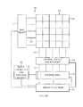
- FIG. 3A shows a block diagram of one example of an image sensor 300 that is suitable for use as the image sensor shown in FIGS. 1A, 1B , and FIG. 2 .
- the illustrated image sensor 300 may include a complementary metal-oxide semiconductor (CMOS) image sensing pixel array 304 .
- CMOS complementary metal-oxide semiconductor
- the architectures and methods disclosed below may also be used with image sensing pixel arrays 304 comprised of charge coupled devices, or other technologies.
- the image sensing pixel array 304 includes multiple pixels 306 arranged in a row and column arrangement. However, other embodiments are not limited to this configuration.
- the pixels 306 in a pixel array 304 can be arranged in any suitable configuration, such as, for example, a hexagon configuration.
- the pixel array 304 can be connected to column select and readout circuitry 308 through one or more output signal lines 310 .
- the column select and readout circuitry 308 includes column circuits that each selectively receives the analog signal read from a pixel 306 in the respective column.
- a group of pixels, such as all of the pixels in the selected row, can be read into each of the column circuits simultaneously for any preprocessing that might be needed. This allows the analog signals from multiple pixels to be converted concurrently to digital form during a single A/D conversion period.
- the pixel array 304 can also be connected to row select circuitry 312 through one or more row select lines 314 .
- the row select circuitry 312 includes row select circuits that selectively activate particular pixels 306 or group of pixels, such as all of the pixels 306 in a selected row, so that the analog signals from the pixels in the selected row are sent over the output signal lines 310 to the select and readout circuitry 308 concurrently.
- the image sensor 300 can include an image processor 302 operatively connected to the row select circuitry 312 , the column select and readout circuitry 308 , the column ADC circuitry 316 , and/or the ramp generator and control circuitry 322 .
- the image processor 302 can provide signals to the row select circuitry 312 and the column select and readout circuitry 308 for the readout of the analog signals from the pixels 306 .
- the image processor 302 may also provide control signals to the ramp generator and control circuitry 322 and the column ADC circuitry 316 .
- the image processor 302 can also process the complete digital representation of the image received from the column ADC circuitry 316 after the A/D conversion of all the pixel values.
- the image sensor 300 and the image processor 302 can be a single integrated circuit, or can be separate circuits.
- a fine conversion step is performed to determine the LSBs.
- multiple fine ramp signals are generated concurrently to be selected for input to the column ADC circuits 316 (2 m fine ramp signals with a given step size/clock cycle; e.g., a step size/clock cycle of 1 LSB).
- the results of the coarse step are used to connect the comparator in a respective column ADC circuit 320 to a respective fine ramp signal that corresponds to the level of its input signal (e.g., MSBs).
- the fine conversion calculates the LSBs over 2 n clock cycles.
- the results of the fine step are also saved in the memory in the column ADC circuits 320 .
- the final digital output from each column ADC circuit 320 is a combination of the results of the coarse and fine conversion steps.
- each comparator is connected to a fine ramp signal that corresponds to its input signal, each fine ramp signal only has to span 1 ⁇ 2 m times the ADC input range. This improves the speed of the A/D conversion process. The amount of time needed for A/D conversion process is less with the MRSS ADCs compared to single slope ADCs.
- the coarse and/or fine ramp signals can be staircase signals, either decreasing or increasing.
- the coarse and/or fine ramp signals could be continuous linear signals.
- FIG. 3B shows a structural block diagram of circuitry 330 for determining and applying such analog error correction.
- the circuit has a digital-to-analog converter (DAC) 332 that, for example, can receive digital control signals such as from the image processor 302 of FIG. 3A .
- the control signals may, for example, implement a change in the full range voltage available for an analog input that is to be digitized.
- the control signals may also implement slope changes for either the coarse or fine ramp signals.
- the ADC 336 provides digital output, which could potentially be in error.
- the added error detection and correction circuitry may be able to detect that one or more bits of the output of ADC 336 are in error, and can implement digital correction 338 to the output.
- the digital correction 338 can be implemented within each A/D conversion cycle.
- the outputs or output errors of the ADC 336 may be averaged over multiple A/D conversion cycles using averager 340 .
- the averager 340 can provide an output to be used as part of a feedback loop and as an input to the analog correction operation 342 .
- the analog correction 342 can provide additional correction of errors in the analog to digital conversion.
- FIG. 4A shows a diagram of an example column ADC, ramp generator and control circuitry, and additional ADCs and error correction circuitry that are suitable for use in the image sensor shown in FIGS. 3A and 3B .
- Column ADC circuitry 400 includes N column ADC circuits that each receives respective input voltage signals Vinp 1 , Vinp 2 , . . . , VinpN from the column select and readout circuitry (e.g., 308 in FIG. 3A ) and produces digital output signals.
- Three column ADCs circuits 402 , 404 , 406 are shown in FIG. 4A .
- Column ADC circuit 402 corresponds to column 1
- column ADC circuit 404 corresponds to column 2
- column ADC circuit 406 corresponds to column N.
- the coarse ramp switch 416 is configured to connect a second input of each comparator 420 to the coarse ramp generator 408 .
- the second input of the comparator 420 is connected to the coarse ramp generator 408 during the coarse step of the two-step A/D conversion process.
- a single slope A/D conversion is performed and the result (i.e., m bits) of each A/D conversion within each column is saved in a respective logic and memory circuitry 422 in the column ADC circuits 402 , 404 , 406 .
- the logic and memory circuitry 422 is also configured to enable (close) and disable (open) the coarse ramp switch 416 and each fine ramp switch 418 .
- the logic and memory circuitry 422 enables the coarse ramp switch 416 to connect the second input of each comparator 420 to the coarse ramp generator 408 .
- the logic and memory circuitry 422 disables the coarse ramp switch 416 at the conclusion of the coarse step.
- the operations include the error measurement, the generation of ramp signals, a calibration process for the column ADC circuitry 316 , and generation of corrected digital outputs representing quantizations of the input voltages received from the pixel array.
- FIG. 4B shows a graph 430 of coarse and fine ramp signals applied to a single column ADC circuit (such as column 402 ) over a single analog-to-digital (A/D) conversion period.
- the single A/D conversion period includes a coarse conversion step 434 that is followed by a fine conversion step 436 .
- the column ADC circuit is configured to provide a digital output corresponding to a quantized level of the input voltage signal Vinp 1 438 that is within the range from 0V to the full range (FR) voltage 440 .
- Vinp 1 is applied to a first input of the comparator in the column ADC circuit.
- a coarse ramp signal 432 is applied to the second input of the comparator.
- the coarse ramp signal 432 can linearly increase from an initial zero voltage to the FR voltage 440 during the coarse conversion step 434 , as shown.
- the coarse ramp signal may be a staircase input.
- the coarse conversion step is divided into four equal time intervals, namely: 0 to t 1 , t 1 to t 2 , t 2 to t 3 , and t 3 to t 4 .
- this implies the comparator trip levels Vtrip[ 0 ], Vtrip[ 1 ], and Vtrip[ 2 ], respectively equal (1 ⁇ 4), (1 ⁇ 2), and (3 ⁇ 4) of the FR voltage 440 .
- the four equal voltage intervals defined by the Vtrip[k] determine the two most significant bits of the coarse conversion step. In the case shown, m is 2.
- the coarse ramp switch 416 is opened, thereby disconnecting the coarse ramp signal 432 from the comparator 420 of the column ADC circuit 402 , and the A/D conversion continues with the fine conversion step 436 .
- the multiple-fine ramp generator 410 then produces four fine ramp signals Vramp[ 0 ] 450 , Vramp[ 1 ] 452 , Vramp[ 2 ] 454 , and Vramp[ 3 ] 456 , one spanning each of the four equal voltage intervals used in the coarse conversion step.
- the four fine ramp signals would be exactly vertically offset from one another by a multiple of the same value Vtrip[ 0 ] 446 , which is (1 ⁇ 4) of the FR voltage 440 .
- each fine ramp signal is used to determine which of eight voltage subintervals of the respective coarse an input voltage signal lies.
- Vramp[ 0 ] 450 for example, would be used to divide the voltage interval 0 to Vtrip[ 0 ] into eight equal subintervals.
- the time span of the fine conversion step 436 thus is divided into eight equal time steps.
- FIG. 5B illustrates a departure from the ideal shown in FIG. 5A , in which there is a positive offset error 518 in Vramp[ 1 ] and a negative offset error 520 in Vramp[ 3 ].
- Such offset or spacing errors in the fine ramp signals can cause errors in triggering times of a comparator in a column ADC converter, leading to digital errors in one or more LSBs during the A/D process.
- the ramp space has 2 n *1[LSB] steps. Errors such as column ADC offset (and its drift) and coarse ramp generator offset (and its drift) can affect the ramp space, which can result in ramp space error or mismatch between the fine ramp signals.
- Each pair of the additional column ADC circuits can be used to measure a ramp space.
- Vtrip [ 0 ] is received by two adjacent comparators (e.g., operational amplifier comparators). In the embodiment shown, these tripping signals are voltage signals, and are determined by the coarse conversion step.
- Vtrip [ 0 ] is received by comparators 600 and 602 .
- the tripping signal Vtrip [ 1 ] is received by comparators 604 and 606 .
- the tripping signal Vtrip [ 2 ] is received by comparators 608 and 610 .
- Comparators 600 and 602 can each receive the fine ramp signals Vramp[ 0 ] or Vramp[ 1 ].
- Comparators 604 and 606 may each receive the fine ramp signals Vramp[ 1 ] or Vramp[ 2 ].
- comparators 608 and 610 can each receive the fine ramp signals Vramp[ 2 ] or Vramp[ 3 ].
- Switches 612 are used to select which fine ramp signals are to be received by the respective comparators. Any suitable type of switch or switch circuitry can be used in each switch 612 .
- a comparison signal representing the comparison between a particular tripping signal and a particular fine ramp signal is output from each comparator.
- Input common mode level dependent offset can be reduced or prevented by using fixed tripping voltage signals and swappable fine ramp signals.
- adjacent fine ramp signals are swapped between measurements.
- the offset in the ramp signal Vramp[ 1 ] causes the time between on/off triggering of the comparators 600 and 602 to be shortened. This causes the time between on/off triggering of the comparators to equal the ramp space minus a time offset.
- Vramp[ 1 ] has a positive offset error from its ideal
- comparator 600 of FIG. 6A having inputs Vtrip[ 0 ] and Vramp[ 0 ]
- comparator 602 of FIG. 6B having inputs Vtrip[ 0 ] and Vramp[ 1 ]
- the offset 602 in the ramp signal Vramp[ 0 ] and Vramp[ 1 ] are swapped between the comparators 600 and 602 .
- comparator 600 of FIG. 6A has inputs Vtrip[ 0 ] and Vramp[ 1 ], with comparator 602 of FIG. 6B having inputs Vtrip[ 0 ] and Vramp[ 0 ].
- This causes the time between on/off triggering of the comparators 600 and 602 to be lengthened to equal the ramp space plus a time offset. When the two timing measurements are averaged, the timing offset is canceled.
- FIG. 7 depicts a schematic diagram of a multiple-fine ramp generator 708 configured for analog adjustment of its multiple fine ramp signals.
- FIG. 7 illustrates four component fine ramp signal generators 700 , 702 , 704 , 706 in the multiple-fine ramp generator 708 .
- the embodiment shown will allow for generation of all four ramp signals shown if FIG. 5A .
- the number of component fine ramp signal generators used in a multiple-fine ramp generator corresponds to the number of fine ramp signals to be produced.
- the number of fine ramp signals can be a power of 2.
- the operation of the first component fine ramp signal generator 700 will now be described.
- the operation of other component fine ramp generators 702 , 704 , 706 is similar, except as noted below.
- the operation is based on using a central node of a bridge circuit as an input to a unity gain or buffer amplifier 726 .
- the components of the bridge include a first signal source I SPACE [ 0 ] 710 , which can be a current source, that connects a source 712 to the central node of the bridge at junction 714 .
- a second signal I SLOPE [ 0 ] 718 which can also be a current source, connects a source 720 into the central node at junction 722 .
- Two sinks connect the central node into the circuit ground. The first of these can be the current sink I COR [ 0 ], and the second can be the variable resistor R LOAD [ 0 ].
- Component fine ramp signal generators 702 , 704 , 706 each have similar bridge inputs, except that for these fine ramp generators the respective sinks I COR [ 1 ], I COR [ 2 ], and I COR [ 3 ] are adjustable.
- the adjustable components in all four fine ramp signal generators can be independently adjustable.
- the signal sources 710 , 716 , 718 each have a fixed signal level, and the variable resistor R LOAD [ 0 ] 724 is used to adjust the output signal, such as an output voltage level, to produce the fine ramp signal Vramp[ 0 ].
- variable current sources I COR [k] can be used to continuously compensate for ramp space error.
- FIG. 8 shows a schematic diagram of an alternate multiple-fine ramp generator comprising four component fine ramp signal generators 802 , 810 , 818 , and 826 .
- a resistance ladder is supplied by the voltage source V IN .
- the number of nodes in the resistance ladder will equal the number of fine ramp signals needed in the particular embodiment.
- all fine ramp signals with equal and correct differences would be produced by adding a single time-varying V OFFSET that decayed linearly (or with equal step size for a staircase signal) during the fine conversion step.
- FIG. 9 shows a flowchart of a method of operating an image sensor.
- the method in FIG. 9 operates continuously. In other embodiments, the method can operate periodically or at select times.
- stage 908 A determination is made at stage 908 as to whether an AFE gain change has occurred. If so, the process passes to stage 910 where one or more of the values I SPACE [k] and I SPACE [k] are adjusted. For example, in one embodiment, the operations of stage 910 can be performed using the techniques disclosed in conjunction with FIGS. 7 and 8 . The method then returns to stage 904 .
- stage 912 a determination is made as to whether a continuous calibration process is to be performed. If not, the method passes to stage 914 where the additional column ADCs are turned off. The additional column ADCs are included in the additional column ADCs and error correction 414 in FIG. 4 .
- stage 916 the process continues at stage 916 where the ramp space error is measured over multiple A/D conversion cycles and averaged.
- the averaged error values are then used to determine one or more averaged error correction values.
- the operations in stage 916 operate continuously while the calibration process is running.
- stage 916 can be performed using the technique disclosed in conjunction with FIG. 4 .
- the averaged error correction values are then updated at stage 918 and applied to the analog stage of the A/D conversion process, such as by modifying operation of the fine ramp generators.
- FIGS. 10 and 11 depict a method of performing a faster initial error measurement, such as at stage 904 of the method of FIG. 9 .
- an accurate fine ramp signal Vramp[n] is needed only around the tripping points Vtrip[n] during the initial error measurement (e.g., stage 904 in FIG. 9 ).
- multiple error measurements are obtained to improve the accuracy of the measurements.
- the fine ramp signals Vramp[n] can abruptly jump as shown in FIGS. 10 and 11 .
- FIG. 11 shows the adjusted fine ramp signals Vramp[ 0 ] through Vramp[ 3 ].
- Each fine ramp signal includes a nonlinear abrupt change, such as a jump 1100 , that implement the removal or exclusion of the section 1000 shown in FIG. 10 .
- FIG. 12 shows a block diagram of an electronic device that includes an image capture device.
- the electronic device 1200 can include one or more processing devices 1202 , storage or memory components 1204 , a power source 1206 , one or more displays 1208 , one or more input/output (I/O) devices 1210 , one or more sensors 1212 , one or more network communication interfaces 1214 , and one or more image capture devices 1216 , each of which will be discussed in turn below.
- I/O input/output
- the one or more processing devices 1202 can be a microprocessor, a central processing unit (CPU), an application-specific integrated circuit (ASIC), a digital signal processor (DSP), or combinations of multiple such devices.
- processing device is meant to encompass a single processor or processing unit, multiple processors, multiple processing units, or other suitably configured computing element or elements.
- the image processor 302 ( FIG. 3A ) can be incorporated into the one or more processing devices 1202 . In other embodiments, the image processor 302 is separate from the processing device(s) 1202 . And in still other embodiments, the operations and processing performed by the image processor 302 can be distributed between the image processor 702 and the processing device(s) 1202 .
- the power source 1206 can be implemented with any device capable of providing energy to the electronic device 1200 .
- the power source 1206 can be a battery or a connection cable that connects the electronic device 1200 to another power source such as a wall outlet.
- the one or more displays 1208 may provide an image or video output for the electronic device 1200 .
- the display(s) 1208 can be substantially any size and may be positioned substantially anywhere on the electronic device 1200 .
- the display(s) 1208 can each be a liquid crystal display element, a plasma display element, or a light emitting diode display element.
- At least one display 1208 may also function as an input device that is configured to receive touch and/or force inputs.
- the display 1208 can include capacitive touch sensors, infrared touch sensors, and the like that may capture a user's input to the display. In these embodiments, a user may press on the display 1208 in order to provide input to the electronic device 1200 .
- the one or more input/output devices 1210 can receive data from a user or one or more other electronic devices.
- the I/O device(s) 1210 can include a touch sensing input surface such as a track pad, one or more buttons, one or more microphones or speakers, and/or a keyboard.
- the one or more sensors 1212 can by implemented with any type of sensor. Examples sensors include, but are not limited to, light sensors and/or light detection sensors, biometric sensors (e.g., fingerprint sensor), gyroscopes, accelerometers, force sensors, proximity sensors, and/or touch sensors.
- the sensor(s) 1212 can be used to provide data to the processing device(s) 1202 , which may be used to enhance or vary functions of the electronic device.
- the one or more image capture devices 1216 can be used to capture images or video.
- An image capture device is a cameral.
- At least one image capture device 1216 can include an image sensor as disclosed herein.
- the image sensor can be implemented as any suitable image sensor, such as a complementary metal-oxide-semiconductor (CMOS) image sensor or a charge coupled device.
- CMOS complementary metal-oxide-semiconductor
- the image capture device(s) 1216 can include an imaging stage that is in optical communication with the image sensor.
- the imaging stage may include conventional elements such as a lens, a filter, an iris, and a shutter.
- Various elements of the image capture device(s) 1216 can be controlled by timing signals or other signals supplied from the processing device(s) 1202 , the image processor 302 ( FIG. 3A ), and/or the memory 1204 .
Abstract
Image sensors using multiple-ramp single slope analog to digital converters (ADCs) and method of their operation are disclosed. The images sensors use additional column ADCs to detect offset errors in the fine ramp signals and feedback in the analog domain to correct the errors. Averaging errors over multiple analog-to-digital conversion cycles allows for improved error correction.
Description
This application claims the benefit under 35 U.S.C. §119(e) of U.S. Provisional Patent Application No. 62/334,426, filed on May 10, 2016, and entitled “Image Sensor With Calibrated Column Analog-to-Digital Converters,” which is incorporated by reference as if fully disclosed herein.
The described embodiments relate generally to image sensors used in various image capture devices. Some embodiments relate more specifically to architectures for analog-to-digital converters (ADC) in image sensors having an array of pixels.
An image sensor typically includes an array of pixels. When an image of a scene is to be captured by the image sensor, each pixel accumulates photo-generated charge based on the amount of light striking the pixel. Column circuits connected to the pixels receive voltage signals from the pixels and convert the voltage signals into digital signals using analog-to-digital converters (ADCs) included in each column circuit. The digital signals are then combined to produce the captured image.
Single slope ADCs are used in many image sensors due at least in part to their linearity and to their limited power consumption. However, for some image sensors, such as large pixel array image sensors, the single slope ADCs can take a relatively long time to convert all of the voltage signals into digital signals. Several readout techniques have been used to reduce the conversion time of the single slop ADCs. One technique places column circuits on two sides of the pixel array (e.g., top and bottom) to improve the readout throughput. Some of the pixels are readout by the column circuits on one side of the pixel array while the remaining pixels are readout by the column circuits on the other side of the pixel array.
Another technique uses multiple banks or groups of column circuits and staggers the use of the column circuits with respect to time. One group of column circuits reads the voltage signals from the pixels while another group of column circuits converts the voltage signals into digital signals. However, both of these techniques can increase the column fixed pattern noise in the digital signals, consume a greater amount of die area, and increase the amount of power consumed by the column circuits.
Embodiments described herein relate to image sensors, including those that use multiple-ramp single slope (MRSS) analog to digital converters (ADC) for processing pixel arrays data.
In one embodiment, an image sensor includes an array of pixels configured in multiple columns. The image sensor uses an MRSS ADC in each column. The image sensor includes an additional number of column ADCs for sampling the fine ramp signals of the MRSS ADC process to detect errors, such as offset, spacing or timing errors, in the fine ramp signals. The detected errors are used by feedback circuitry to modify one or more fine ramp signal generators in the analog domain. Further embodiments use detection of errors in the fine ramp signals over multiple analog-to-digital (A/D) conversions to obtain improved error estimation and correction.
Another embodiment discloses a method of operating an image sensor that uses MRSS ADC. The method includes receiving an initiation signal, and performing an initial error measurement using additional column ADC to measure errors in the fine ramp signals. An initial analog error correction is performed using the initial error measurement. Thereafter subsequent ramp signal errors can be continually measured over subsequent A/D conversion periods. This can refine the error measurement values to allow for improved error correction. In some embodiments analog error correction can include any of: adjusting an offset voltage applied to an amplifier of a fine ramp generator or adjusting a current source of a fine ramp generator.
Another embodiment is of an electronic device comprising a camera that contains an image sensor that uses MRSS ADC for processing data from an array of pixels, and an image processor for control of the image sensor. The image sensor includes a second set of column analog ADC configured to measure the fine ramp signals. The image sensor includes an error detection circuit to determine one or more errors in the fine ramp signals and feedback circuitry that can reduce the errors in the fine ramp signals based on the determined error.
The disclosure will be readily understood by the following detailed description in conjunction with the accompanying drawings, wherein like reference numerals designate like structural elements, and in which:
The use of cross-hatching or shading in the accompanying figures is generally provided to clarify the boundaries between adjacent elements and also to facilitate legibility of the figures. Accordingly, neither the presence nor the absence of cross-hatching or shading conveys or indicates any preference or requirement for particular materials, material properties, element proportions, element dimensions, commonalities of similarly illustrated elements, or any other characteristic, attribute, or property for any element illustrated in the accompanying figures.
Additionally, it should be understood that the proportions and dimensions (either relative or absolute) of the various features and elements (and collections and groupings thereof) and the boundaries, separations, and positional relationships presented therebetween, are provided in the accompanying figures merely to facilitate an understanding of the various embodiments described herein and, accordingly, may not necessarily be presented or illustrated to scale, and are not intended to indicate any preference or requirement for an illustrated embodiment to the exclusion of embodiments described with reference thereto.
Reference will now be made in detail to representative embodiments illustrated in the accompanying drawings. It should be understood that the following descriptions are not intended to limit the embodiments to one preferred embodiment. To the contrary, it is intended to cover alternatives, modifications, and equivalents as can be included within the spirit and scope of the described embodiments as defined by the appended claims.
The following disclosure relates to an image sensor that includes multiple-ramp single slope analog-to-digital converters (MRSS ADCs) in the column circuits. As explained below, ideal analog to digital conversion in such architectures requires precise generation of the coarse and fine ramp signals.
As imperfections in timing and signal generation can occur, this disclosure provides architectures and methods for detecting offsets or other inaccuracies in the coarse and fine ramp signals. Some embodiments provide additional column ADCs for detection of errors in the fine ramp signals.
This disclosure also provides calibration techniques for the MRSS ADCs that make use of the detected inaccuracies. In some embodiments the calibration techniques use feedback of the detected inaccuracies into the analog stages. In some embodiments the feedback is into the fine ramp signal generators.
In some embodiments offset or spacing errors between fine ramp signals are determined over multiple analog-to-digital (A/D) conversion periods. Detecting and correcting such errors in the fine ramp signals over a single A/D conversion period can allow for increasing conversion accuracy to 1 least significant bit (LSB). However, when such errors are measured and averaged over multiple A/D conversion periods it can be possible to obtain conversion accuracy to less than 1 LSB. Such accuracy allows for more accurate reconstruction of images acquired with the image sensors. It can eliminate artifacts such as visible lines or streaks in the reconstructed images.
These and other embodiments are discussed below with reference to FIGS. 1-12 . However, those skilled in the art will readily appreciate that the detailed description given herein with respect to these Figures is for explanatory purposes only and should not be construed as limiting.
In the illustrated embodiment, the electronic device 100 is depicted as a smart telephone. Other embodiments, however, are not limited to this construction. Other types of computing or electronic devices can include one or more cameras. Examples of such electronic devices include, but are not limited to, laptop computer, tablet computing devices, digital cameras, wearable electronics or communication devices, scanners, video recorders, and copiers.
The enclosure 106 can form an outer surface or partial outer surface for the internal components of the electronic device 100, and may support and/or at least partially surround the display 108 and the I/O device 110. The enclosure 106 can be formed of one or more components operably connected together, such as a front piece and a back piece. Alternatively, the enclosure 106 can be formed of a single piece operably connected to the display 108.
The I/O device 110 can be implemented with any type of input and/or output device. By way of example only, the I/O device 110 is shown as a button, but in other embodiments the I/O device can be a switch, a capacitive sensor, or other input mechanism. The I/O device 110 allows a user to interact with the electronic device 100. For example, the I/O device 110 may be a button or switch to alter the volume, return to a home screen, and the like.
In some embodiments, the electronic device 100 can include one or more input devices, output devices, and/or I/O devices, and each device can have a single function or multiple functions. Example input, output, and I/O devices include, but are not limited to, a microphone, speakers, a touch sensor, network or communication ports, and wireless communication devices.
The display 108 can provide a visual output for the electronic device 100. The display 108 can be implemented with any type of suitable display element, such as a retina display, a color liquid crystal display (LCD) element, or an organic light-emitting display (OLED) element. In some embodiments, the display 108 can be configured to receive user inputs to the electronic device 100. For example, the display 108 can be a multi-touch capacitive touchscreen that can detect one or more user touch and/or force inputs.
The camera 102 includes an imaging stage 200 that is in optical communication with an image sensor 202. The imaging stage 200 is operably connected to the enclosure 106 and positioned in front of the image sensor 202. The imaging stage 200 can include conventional elements such as a lens, a filter, an iris, and a shutter. The imaging stage 200 directs, focuses, and/or transmits light 204 within its field of view onto the image sensor 202. The image sensor 202 captures one or more images of a subject scene by converting the incident light into electrical signals.
The image sensor 202 is formed in and/or supported by a support structure 206. The support structure 206 can be a semiconductor-based material including, but not limited to, silicon, silicon-on-insulator (SOI) technology, silicon-on-sapphire (SOS) technology, doped and undoped semiconductors, epitaxial layers formed on a semiconductor substrate, well regions or buried layers formed in a semiconductor substrate, and other semiconductor structures.
Various elements of the imaging stage 200 or the image sensor 202 can be controlled by timing signals or other signals supplied from a processor or memory (see, e.g., 302 in FIG. 3A or 1202 in FIG. 12 ). Some or all of the elements in the imaging stage 200 can be integrated into a single component. Additionally, some or all of the elements in the imaging stage 200 can be integrated with the image sensor 202, and possibly one or more additional elements of the electronic device 200, to form a camera module. For example, a processor or a memory may be integrated with the image sensor 202 in some embodiments.
Each pixel 306 can include a photosensitive region (not shown) that accumulates charge when an image is captured. An analog signal, such as a voltage signal, is read from each pixel that represents the amount of charge accumulated by the photosensitive region. During a single analog to digital (A/D) conversion period the analog signal of a pixel is then converted to one of a finite set of quantized values which is then represented in digital form.
The pixel array 304 can be connected to column select and readout circuitry 308 through one or more output signal lines 310. The column select and readout circuitry 308 includes column circuits that each selectively receives the analog signal read from a pixel 306 in the respective column. A group of pixels, such as all of the pixels in the selected row, can be read into each of the column circuits simultaneously for any preprocessing that might be needed. This allows the analog signals from multiple pixels to be converted concurrently to digital form during a single A/D conversion period.
The pixel array 304 can also be connected to row select circuitry 312 through one or more row select lines 314. The row select circuitry 312 includes row select circuits that selectively activate particular pixels 306 or group of pixels, such as all of the pixels 306 in a selected row, so that the analog signals from the pixels in the selected row are sent over the output signal lines 310 to the select and readout circuitry 308 concurrently.
Column analog-to-digital (ADC) circuitry 316 is connected to the column select and readout circuitry 308 through one or more signal lines 318. The column ADC circuitry 316 includes column ADC circuits 320 that receive signals, such as voltage signals, from the column select and readout circuitry 308. The column ADC circuitry 316 then converts the signals into digital signals. The set of the digital signals from all the pixels forms a digital representation of the image. The column select and readout circuitry 308 can include analog front end (AFE) circuitry, such as buffer amplifiers for the voltages from the pixels 306, and correlated double sampling (CDS) circuitry. The AFE circuitry can provide signals to the column ADC circuitry 316 regarding values, such as voltage ranges or timing values, to be used by the column ADC circuitry 316 during the A/D conversion of the image. Each column ADC circuit 320 may use comparators or other comparison circuitry to produce a quantized digital value.
In some embodiments, signals from the pixels 306 in one row of the pixel array 304 undergo A/D conversion in parallel during a single A/D conversion period. In some architectures it may be that the rows are processed in parallel.
The column ADC circuitry 316 is connected to ramp generator and control circuitry 322. As is described in more detail in conjunction with FIG. 3B and FIGS. 4A-4B , the ramp generator and control circuitry 322 can include counter and control circuitry, a coarse ramp generator, a multiple-fine ramp generator, and a set of additional column ADCs and error correction circuitry.
The image sensor 300 can include an image processor 302 operatively connected to the row select circuitry 312, the column select and readout circuitry 308, the column ADC circuitry 316, and/or the ramp generator and control circuitry 322. The image processor 302 can provide signals to the row select circuitry 312 and the column select and readout circuitry 308 for the readout of the analog signals from the pixels 306. The image processor 302 may also provide control signals to the ramp generator and control circuitry 322 and the column ADC circuitry 316. The image processor 302 can also process the complete digital representation of the image received from the column ADC circuitry 316 after the A/D conversion of all the pixel values. The image sensor 300 and the image processor 302 can be a single integrated circuit, or can be separate circuits.
The column ADC circuits 316 are each configured as multiple-ramp single slope (MRSS) ADC circuits. Generally, each MRSS ADC circuit employs a two-step conversion process to perform a single complete analog-to-digital conversion: a coarse conversion step and a fine conversion step. The resolution of the MRSS ADC circuit is m+n, where m is the number of most significant bits (MSB) and n is the number of least significant bits (LSBs). The coarse step connects a single coarse ramp signal having 2m−1 coarse levels (e.g., voltages) to each of the comparators in the column ADC circuits 316. A single slope analog-to-digital (A/D) conversion is then performed in each column ADC circuit 320. The results of the coarse step are saved in a memory in each column ADC circuit 320.
After the coarse conversion step, a fine conversion step is performed to determine the LSBs. During the fine conversion step multiple fine ramp signals are generated concurrently to be selected for input to the column ADC circuits 316 (2m fine ramp signals with a given step size/clock cycle; e.g., a step size/clock cycle of 1 LSB). As will be explained in more detail below in FIG. 4A , the results of the coarse step are used to connect the comparator in a respective column ADC circuit 320 to a respective fine ramp signal that corresponds to the level of its input signal (e.g., MSBs). The fine conversion calculates the LSBs over 2n clock cycles. The results of the fine step are also saved in the memory in the column ADC circuits 320. The final digital output from each column ADC circuit 320 is a combination of the results of the coarse and fine conversion steps.
Because each comparator is connected to a fine ramp signal that corresponds to its input signal, each fine ramp signal only has to span ½m times the ADC input range. This improves the speed of the A/D conversion process. The amount of time needed for A/D conversion process is less with the MRSS ADCs compared to single slope ADCs.
In some embodiments the coarse and/or fine ramp signals can be staircase signals, either decreasing or increasing. Alternatively, the coarse and/or fine ramp signals could be continuous linear signals.
An image sensor 202, such as the embodiment shown in FIG. 3A , can be supplemented with error correction capabilities to account for departures from the ideal operation just described. For example, offsets and drifts in the comparators, or other component drifts or inaccuracies, can cause errors, such as timing errors or voltage offset errors between the fine ramp signal (also called spacing errors). As will now be described, the various embodiments employ circuitry and methods for detection and correction of the errors in the digital output produced by non-ideal components or operation. In general, various embodiments can use not only detection of errors within each conversion step, but can also use averaging of errors over multiple conversion steps. Further, the detected errors can be used both to provide a digital correction to digital outputs, but can also be used as part of feedback circuitry to provide error correction at the analog input stage of the ADC circuitry. Together with averaging of errors, such analog feedback and adjustment of the ADC circuitry can be able to provide better than 1 LSB accuracy.
The analog output of the DAC is added to feedback analog corrections 342, such as may have been determined by the circuitry and methods to be described below. The sum of the two analog signals can be used to adjust 334 component inputs, such as a comparator voltage offset VOFFSET, which is used as part of an analog-to-digital converter (ADC) 366. The ADC 336 may, for example, be the column ADC circuits 316 of FIG. 3A that receive analog inputs from an array of pixels.
The ADC 336 provides digital output, which could potentially be in error. The added error detection and correction circuitry may be able to detect that one or more bits of the output of ADC 336 are in error, and can implement digital correction 338 to the output. The digital correction 338 can be implemented within each A/D conversion cycle.
The outputs or output errors of the ADC 336 may be averaged over multiple A/D conversion cycles using averager 340. The averager 340 can provide an output to be used as part of a feedback loop and as an input to the analog correction operation 342. When initial digital corrections to the output of the ADC 336 are implemented first by the digital correction operation 388, the analog correction 342 can provide additional correction of errors in the analog to digital conversion.
The coarse ramp generator 408, multiple-fine ramp generator 410, and counter and control circuitry 412 are all elements of the ramp generator and control circuitry 322 of FIG. 3A . Still with respect to FIG. 4A , the coarse ramp generator 408 produces the coarse ramp signal during the coarse step of the two-step conversion process. The multiple-fine ramp generator 410 outputs multiple fine ramp signals concurrently during the fine step of the two-step A/D conversion process.
Each column ADC circuit in the column ADC circuitry 400 includes a coarse ramp switch 416, multiple fine ramp switches 418, a comparator 420, and logic and memory circuitry 422. The analog input voltage signals Vinp1, Vinp2, and VinpN are received from the column select and readout circuitry (e.g., 308 in FIG. 3A ). A first input of the comparator 420 is connected to the input voltage signal Vinp1. Similarly, input voltage signals Vinp2 to VinpN (N representing the total number of column ADC circuits) are connected to respective first inputs of the comparators in column 2 (402) to column N (406).
The coarse ramp switch 416 is configured to connect a second input of each comparator 420 to the coarse ramp generator 408. The second input of the comparator 420 is connected to the coarse ramp generator 408 during the coarse step of the two-step A/D conversion process. As described earlier, during the coarse step all of the comparators 420 are connected to a single coarse ramp signal having 2m−1 coarse levels (where m=MSB bits). A single slope A/D conversion is performed and the result (i.e., m bits) of each A/D conversion within each column is saved in a respective logic and memory circuitry 422 in the column ADC circuits 402, 404, 406.
The fine ramp switches 418 are each configured to transmit to the second input of the respective comparators 420 a selected fine ramp signal produced by the multiple-fine ramp generator 410. As discussed earlier, multiple fine ramp signals are produced during the fine step of the two-step A/D conversion process. The results of the coarse step are used to connect each comparator 420 to the multiple-fine ramp generator 410 and transmit a respective fine ramp signal that corresponds to the level of an input signal (e.g., Vinp1, Vinp2, . . . , VinpN). The results of the fine step are also saved in the logic and memory circuitry 422 of the each column ADC circuits 402, 404, and 406. The final digital outputs (Vout) from each column circuit 402, 404, and 406 are combinations of the results of the coarse and fine conversion steps, i.e., m+n bits.
The logic and memory circuitry 422 is also configured to enable (close) and disable (open) the coarse ramp switch 416 and each fine ramp switch 418. The logic and memory circuitry 422 enables the coarse ramp switch 416 to connect the second input of each comparator 420 to the coarse ramp generator 408. The logic and memory circuitry 422 disables the coarse ramp switch 416 at the conclusion of the coarse step.
The logic and memory circuitry 422 then enables a respective fine ramp switch 418 to connect the second input of each comparator 420 to a particular fine ramp signal. The results of the coarse step of the two-step A/D conversion are used to determine which of the fine ramp switches 418 are enabled. The logic and memory 422 disables the enabled fine ramp switches at the conclusion of the fine step.
Various operations of the coarse and multiple-fine ramp generators, the control circuitry 322, and the additional column ADCs and error correction 414 will now be described. The operations include the error measurement, the generation of ramp signals, a calibration process for the column ADC circuitry 316, and generation of corrected digital outputs representing quantizations of the input voltages received from the pixel array.
During the coarse conversion step 434, a coarse ramp signal 432 is applied to the second input of the comparator. In some embodiments the coarse ramp signal 432 can linearly increase from an initial zero voltage to the FR voltage 440 during the coarse conversion step 434, as shown. However, in other embodiments the coarse ramp signal may be a staircase input. An example of such a staircase signal would output values at comparator trip (or “tripping”) values; i.e., the staircase signal would have values equal: 0V during time 0 to t1; value Vtrip[0] 446 during time interval t1 to t2; value Vtrip[1] 444 during time interval t2 to t3; and value Vtrip[2] 442 during time interval t3 to t4; with t4 being the end of the coarse conversion step. Other increasing waveforms that take on the Vtrip[k] values at known times over the coarse conversion step may also be used.
In the embodiment shown, the coarse conversion step is divided into four equal time intervals, namely: 0 to t1, t1 to t2, t2 to t3, and t3 to t4. For a linear coarse ramp signal this implies the comparator trip levels Vtrip[0], Vtrip[1], and Vtrip[2], respectively equal (¼), (½), and (¾) of the FR voltage 440. The four equal voltage intervals defined by the Vtrip[k] determine the two most significant bits of the coarse conversion step. In the case shown, m is 2.
With coarse ramp 432 and Vinp1 applied to the comparator of the ADC circuit, the comparator's outputs are measured by logic and memory circuitry, such as 422, at the times t1, t2, t3, and t4. For the values shown, the comparator first has positive output at t2, so that the logic and memory circuit produces MSB values of 01, indicating that the value of Vinp1 is between Vtrip[0] and Vtrip[1], i.e., between (¼) and (½) of the FR voltage 440.
At the completion of coarse conversion step 434, the coarse ramp switch 416 is opened, thereby disconnecting the coarse ramp signal 432 from the comparator 420 of the column ADC circuit 402, and the A/D conversion continues with the fine conversion step 436. The multiple-fine ramp generator 410 then produces four fine ramp signals Vramp[0] 450, Vramp[1] 452, Vramp[2] 454, and Vramp[3] 456, one spanning each of the four equal voltage intervals used in the coarse conversion step. Ideally the four fine ramp signals would be exactly vertically offset from one another by a multiple of the same value Vtrip[0] 446, which is (¼) of the FR voltage 440.
In the embodiment shown, during the fine conversion step 436 the fine ramp signals are used to obtain n=3 LSB, i.e., each fine ramp signal is used to determine which of eight voltage subintervals of the respective coarse an input voltage signal lies. In the embodiment shown, Vramp[0] 450, for example, would be used to divide the voltage interval 0 to Vtrip[0] into eight equal subintervals. The time span of the fine conversion step 436 thus is divided into eight equal time steps.
In the embodiment shown, at the start of the fine conversion step 436, the fine ramp switch 418 closes to apply Vramp[1] to the second input of the comparator. Analogous to the operation during the coarse conversion step, the value of the comparator is taken at the end time of each time step. For the end time at which the comparator first had a positive output, the logic and memory circuit 422 produces the corresponding 3-bit output. In the embodiment shown, for Vinp1 438 and Vramp[1] 452 applied to the inputs of the comparator, the comparator has a positive output at the end of the fourth time step, indicating that Vinp1 438 is between (⅜) and (4/8) of the voltage range Vtrip[0] to Vtrip[1]. The corresponding three LSBs generated by the logic and memory circuit 422 are 011.
Either or both of the coarse ramp signal and the set of the fine ramp signals can be decreasing signals rather than increasing. Further, as mentioned in regard to the coarse ramp signal, the fine ramp signals can be staircase signals, i.e., constant during each the eight time steps but with a uniform jump at the end of each time step.
The simplified example of an MRSS ADC process just presented represents ideal behavior of all components, such as the comparators, and the coarse and multiple-fine ramp generators. Embodiments will now be presented that can measure and reduce errors produced by departures form ideal performance.
Ideally, the ramp space has 2n*1[LSB] steps. Errors such as column ADC offset (and its drift) and coarse ramp generator offset (and its drift) can affect the ramp space, which can result in ramp space error or mismatch between the fine ramp signals. Each pair of the additional column ADC circuits can be used to measure a ramp space.
In the embodiment shown in FIG. 6A , fixed tripping signals Vtrip [0], Vtrip[1], Vtrip [2] are received by two adjacent comparators (e.g., operational amplifier comparators). In the embodiment shown, these tripping signals are voltage signals, and are determined by the coarse conversion step. Vtrip [0] is received by comparators 600 and 602. The tripping signal Vtrip [1] is received by comparators 604 and 606. Likewise, the tripping signal Vtrip [2] is received by comparators 608 and 610.
The fine ramp signals Vramp[k], for k=0 . . . 3, are swappable between two adjacent comparators. Comparators 600 and 602 can each receive the fine ramp signals Vramp[0] or Vramp[1]. Comparators 604 and 606 may each receive the fine ramp signals Vramp[1] or Vramp[2]. Further, comparators 608 and 610 can each receive the fine ramp signals Vramp[2] or Vramp[3]. Switches 612 are used to select which fine ramp signals are to be received by the respective comparators. Any suitable type of switch or switch circuitry can be used in each switch 612.
A comparison signal representing the comparison between a particular tripping signal and a particular fine ramp signal is output from each comparator. Input common mode level dependent offset can be reduced or prevented by using fixed tripping voltage signals and swappable fine ramp signals. In one embodiment, adjacent fine ramp signals are swapped between measurements.
In FIG. 6B the offset in the ramp signal Vramp[1] causes the time between on/off triggering of the comparators 600 and 602 to be shortened. This causes the time between on/off triggering of the comparators to equal the ramp space minus a time offset. For the particular case of the error shown in FIG. 5B in which Vramp[1] has a positive offset error from its ideal, with comparator 600 of FIG. 6A having inputs Vtrip[0] and Vramp[0], and comparator 602 of FIG. 6B having inputs Vtrip[0] and Vramp[1], it follows that the time from when comparator 602 turns on to the time when comparator 600 triggers on is reduced.
In FIG. 6C the offset 602 in the ramp signal Vramp[0] and Vramp[1] are swapped between the comparators 600 and 602. In this case comparator 600 of FIG. 6A has inputs Vtrip[0] and Vramp[1], with comparator 602 of FIG. 6B having inputs Vtrip[0] and Vramp[0]. This causes the time between on/off triggering of the comparators 600 and 602 to be lengthened to equal the ramp space plus a time offset. When the two timing measurements are averaged, the timing offset is canceled.
The operation of the first component fine ramp signal generator 700 will now be described. The operation of other component fine ramp generators 702, 704, 706 is similar, except as noted below. The operation is based on using a central node of a bridge circuit as an input to a unity gain or buffer amplifier 726. The components of the bridge include a first signal source ISPACE[0] 710, which can be a current source, that connects a source 712 to the central node of the bridge at junction 714. A second signal ISLOPE[0] 718, which can also be a current source, connects a source 720 into the central node at junction 722. Two sinks connect the central node into the circuit ground. The first of these can be the current sink ICOR[0], and the second can be the variable resistor RLOAD[0].
Component fine ramp signal generators 702, 704, 706 each have similar bridge inputs, except that for these fine ramp generators the respective sinks ICOR[1], ICOR[2], and ICOR[3] are adjustable. The adjustable components in all four fine ramp signal generators can be independently adjustable.
During a single fine conversion step, in the component fine ramp signal generator 700, the signal sources 710, 716, 718 each have a fixed signal level, and the variable resistor RLOAD[0] 724 is used to adjust the output signal, such as an output voltage level, to produce the fine ramp signal Vramp[0]. The variation of all the load resistors RLOAD[k], for k=0 . . . 3, can be varied concurrently at the time steps of the fine conversion process.
The signal source ISLOPE[0] 718 can be set based on a desired slope of the fine ramp signals, which can be determined by the output voltage range to be spanned the fine ramp signal and the time of the fine ramp conversion step. In some embodiments the values of ISLOPE[k], k=0 . . . 3, is set at a common reference level.
The signal sources ISPACE[k], k=0 . . . 3, are set to provide the relative vertical shifts in the outputs of the fine ramp signals Vramp[k], for k=0 . . . 3. In one embodiment, this is accomplished by setting ISPACE[3] to a particular value, and then setting ISPACE[2]=2*ISPACE[3], ISPACE[1]=3*ISPACE[3], and ISPACE[0]=4*ISPACE[3].
While the values of the ISLOPE[k] and ISPACE[k] are typically constant over successive fine ramp conversion steps, they can be modified to account for desired changes in the operation of imaging system, such as adjustment for changes in the ambient light detected by the camera 104, or other changes in the AFE. Such desired changes can require changes in the times for the coarse or fine conversion steps, or for the full range voltage. In some embodiments, such changes in any of the values of any of ISLOPE[k] and ISPACE[k] can be caused by signals received from the image processor 302.
The variable current sources ICOR[k] can be used to continuously compensate for ramp space error. ICOR[0] can be set one value, such as midpoint of its allowed range. Thereafter, the values of ICOR[k], for k=1 . . . 3, are varied based on the needed corrections as determined by the methods and circuits described above. As described above, varying ICOR[k] allows for continuous and analog correction of spacing errors in the fine ramp signals.
Each fine ramp signal can then be made to vary over time by addition of offset voltages VOFFSET[k], k=0 . . . 3, at the summing junctions 806, 814, 822, and 830 to respective unity gain or buffer amplifiers 808, 816, 824, and 832. Generally, all fine ramp signals with equal and correct differences, as in FIG. 5A , would be produced by adding a single time-varying VOFFSET that decayed linearly (or with equal step size for a staircase signal) during the fine conversion step.
Departures from these ideals, such as variation in the gains or offsets of the unity gain amplifiers and in the resistances in the ladder, can produce spacing (offset) errors between the fine ramp signals, as shown in FIGS. 5B, 5C . However, by the error detection and error averaging operations discussed previously, the errors can be corrected at the analog stage by applying adjusted and possibly different offset voltages VOFFSET[k] at the summing junctions 806, 814, 822, and 830 to the unity gain amplifiers 808, 816, 824, and 832.
Initially, at stage 900, the components of the image sensor, including column ADC circuitry, row and column select circuitry, coarse and fine ramp generators, and control circuitry, are turned on. After a power-up wait time period passes, or after an analog front end (AFE) gain change, an initial error measurement is determined (stages 902 and 904). An initial error correction is then performed at stage 906.
A determination is made at stage 908 as to whether an AFE gain change has occurred. If so, the process passes to stage 910 where one or more of the values ISPACE[k] and ISPACE[k] are adjusted. For example, in one embodiment, the operations of stage 910 can be performed using the techniques disclosed in conjunction with FIGS. 7 and 8 . The method then returns to stage 904.
When an AFE gain change has not occurred at stage 908, the process continues at stage 912 where a determination is made as to whether a continuous calibration process is to be performed. If not, the method passes to stage 914 where the additional column ADCs are turned off. The additional column ADCs are included in the additional column ADCs and error correction 414 in FIG. 4 .
When a continuous calibration process is to be performed, the process continues at stage 916 where the ramp space error is measured over multiple A/D conversion cycles and averaged. The averaged error values are then used to determine one or more averaged error correction values. In some embodiments, the operations in stage 916 operate continuously while the calibration process is running. For example, in one embodiment, stage 916 can be performed using the technique disclosed in conjunction with FIG. 4 . The averaged error correction values are then updated at stage 918 and applied to the analog stage of the A/D conversion process, such as by modifying operation of the fine ramp generators.
The one or more processing devices 1202 can control some or all of the operations of the electronic device 1200. The processing device(s) 1202 can communicate, either directly or indirectly, with substantially all of the components of the electronic device 1200. For example, one or more system buses 1218 or other communication mechanisms can provide communication between the processing device(s) 1202, the storage or memory components 1204, the power source 1206, the display(s) 1208, the I/O device(s) 1210, the sensor(s) 1212, the network communication interface(s) 1214, and the one or more image capture devices 1216. The processing device(s) 1202 can be implemented as any electronic device capable of processing, receiving, or transmitting data or instructions. For example, the one or more processing devices 1202 can be a microprocessor, a central processing unit (CPU), an application-specific integrated circuit (ASIC), a digital signal processor (DSP), or combinations of multiple such devices. As described herein, the term “processing device” is meant to encompass a single processor or processing unit, multiple processors, multiple processing units, or other suitably configured computing element or elements.
In some embodiments, the image processor 302 (FIG. 3A ) can be incorporated into the one or more processing devices 1202. In other embodiments, the image processor 302 is separate from the processing device(s) 1202. And in still other embodiments, the operations and processing performed by the image processor 302 can be distributed between the image processor 702 and the processing device(s) 1202.
The memory 1204 can store electronic data that can be used by the electronic device 1200. For example, the memory 1204 can store electrical data or content such as, for example, audio files, document files, timing signals, control signals, algorithms, and image data. In one embodiment, the memory 1204 stores instructions that when executed by a processor (such as image processor 302 in FIG. 3A ) or by the one or more processing devices 1202, perform the calibration method shown in FIG. 9 and/or the measurement operations and/or the correction operations discussed herein. In other embodiments, a separate memory can be included in or connected to the image processor 302 (FIG. 3A ) and store the instructions that when executed, perform the calibration method shown in FIG. 9 and/or the measurement operations and/or the correction operations discussed herein.
The memory 1204 can be configured as any type of memory. By way of example only, memory 1204 can be implemented as random access memory, read-only memory, Flash memory, removable memory, or other types of storage elements, in any combination.
The power source 1206 can be implemented with any device capable of providing energy to the electronic device 1200. For example, the power source 1206 can be a battery or a connection cable that connects the electronic device 1200 to another power source such as a wall outlet.
The one or more displays 1208 may provide an image or video output for the electronic device 1200. The display(s) 1208 can be substantially any size and may be positioned substantially anywhere on the electronic device 1200. In some embodiments, the display(s) 1208 can each be a liquid crystal display element, a plasma display element, or a light emitting diode display element. At least one display 1208 may also function as an input device that is configured to receive touch and/or force inputs. For example, the display 1208 can include capacitive touch sensors, infrared touch sensors, and the like that may capture a user's input to the display. In these embodiments, a user may press on the display 1208 in order to provide input to the electronic device 1200.
In some embodiments, the one or more input/output devices 1210 can receive data from a user or one or more other electronic devices. The I/O device(s) 1210 can include a touch sensing input surface such as a track pad, one or more buttons, one or more microphones or speakers, and/or a keyboard.
The one or more sensors 1212 can by implemented with any type of sensor. Examples sensors include, but are not limited to, light sensors and/or light detection sensors, biometric sensors (e.g., fingerprint sensor), gyroscopes, accelerometers, force sensors, proximity sensors, and/or touch sensors. The sensor(s) 1212 can be used to provide data to the processing device(s) 1202, which may be used to enhance or vary functions of the electronic device.
The one or more network communication interfaces 1214 can facilitate the transmission and/or receipt of data to or from other electronic devices. For example, in embodiments where the electronic device 1200 is a smart telephone, the network communication interface(s) 1214 can receive data from a network or send and transmit electronic signals via a wireless or wired connection. Example wireless and wired connections include, but are not limited to, cellular, Wi-Fi, Bluetooth, and Ethernet. In one or more embodiments, a single network communication interface 1214 supports multiple network or communication mechanisms. For example, a single network communication interface 1214 can pair with another device over a Bluetooth network to transfer signals to the other device while simultaneously receiving signals from a Wi-Fi or other wired or wireless connection.
The one or more image capture devices 1216 can be used to capture images or video. One example of an image capture device is a cameral. At least one image capture device 1216 can include an image sensor as disclosed herein. The image sensor can be implemented as any suitable image sensor, such as a complementary metal-oxide-semiconductor (CMOS) image sensor or a charge coupled device. As described earlier, the image capture device(s) 1216 can include an imaging stage that is in optical communication with the image sensor. The imaging stage may include conventional elements such as a lens, a filter, an iris, and a shutter. Various elements of the image capture device(s) 1216, such as the imaging stage and/or the image sensor, can be controlled by timing signals or other signals supplied from the processing device(s) 1202, the image processor 302 (FIG. 3A ), and/or the memory 1204.
The foregoing description, for purposes of explanation, used specific nomenclature to provide a thorough understanding of the described embodiments. However, it will be apparent to one skilled in the art that the specific details are not required in order to practice the described embodiments. Thus, the foregoing descriptions of the specific embodiments described herein are presented for purposes of illustration and description. They are not targeted to be exhaustive or to limit the embodiments to the precise forms disclosed. It will be apparent to one of ordinary skill in the art that many modifications and variations are possible in view of the above teachings.
Claims (20)
1. An image sensor comprising:
an array of pixels configured in multiple columns;
a multiple-ramp single slope analog-to-digital conversion circuit operatively connected to the array of pixels and comprising:
a respective column analog-to-digital converter (ADC) for each of the multiple columns, each column ADC configured to receive a signal generated from a pixel in its column as a first input;
a coarse ramp generator operative to apply a coarse ramp signal as a second input to each column ADC during a coarse conversion step within an analog to digital conversion period; and
a plurality of fine ramp generators, each fine ramp generator operative to apply a respective fine ramp signal as the second input to each column ADC during a fine conversion step within the analog to digital conversion period;
a plurality of additional column ADCs configured to measure the fine ramp signals;
an error detection circuit operative to determine an error in at least one fine ramp signal, based on outputs from the plurality of additional column ADCs; and
feedback circuitry operative to modify an operation of at least one fine ramp generator based on the error determined by the error detection circuit.
2. The image sensor of claim 1 , wherein the error detection circuit is operative to:
apply a first fine ramp signal and a trip level of the coarse ramp signal to a first comparator;
apply a second fine ramp signal and the trip level of the coarse ramp signal to a second comparator;
measure a first time between triggering of the first comparator and triggering of the second comparator;
apply the second fine ramp signal and the trip level of the coarse ramp signal to the first comparator;
apply the first fine ramp signal and the trip level of the coarse ramp signal to the second comparator;
measure a second time between triggering of the first comparator and triggering of the second comparator; and
average the first measured time and the second measured time; wherein:
the first fine ramp signal and the second fine ramp signal are adjacent fine ramp signals.
3. The image sensor of claim 2 , wherein:
the first comparator is a component of a first of the additional column ADCs;
the second comparator is a component of a second of the additional column ADCs;
the first measured time is during a first fine conversion step; and
the second measured time is during a next fine conversion step after the first fine conversion step.
4. The image sensor of claim 1 , wherein the feedback circuitry is operative to modify an offset voltage of at least one of the plurality of fine ramp generators.
5. The image sensor of claim 1 , wherein the feedback circuitry is operative to modify a current source of at least one of the plurality of fine ramp generators.
6. The image sensor of claim 1 , wherein the error detection circuit is operative to average errors in at least one ramp signal determined during each of multiple analog to digital conversion periods.
7. The image sensor of claim 6 , wherein the averaged errors are used to modify digital output of a column ADC.
8. The image sensor of claim 6 , wherein the averaged errors are used to modify operation of the fine ramp generators.
9. A method of operating an image sensor that includes multiple-ramp single slope analog-to-digital converters (ADCs), and additional ADCs, the method comprising:
receiving an initiation signal;
using the additional column ADCs to perform an initial error measurement of ramp signals produced by a set of ramp generators;
performing an initial analog error correction on at least one of the set of ramp generators;
performing a subsequent error measurement of the ramp signals, using the additional column ADCs, during operation of the image sensor; and
performing a subsequent analog error correction on at least one of the set of ramp generators;
wherein:
the initial and subsequent analog error corrections comprise at least one of adjusting an offset voltage applied to one of the set of ramp generators or adjusting a current source within one of the set of ramp generators.
10. The method of operating an image sensor of claim 9 , further comprising:
receiving a signal from an analog front end associated with the image sensor; and
changing a property of at least one of the set of ramp generators based on the received signal value.
11. The method of operating an image sensor of claim 10 , wherein the signal from the analog front end comprises is of a change in a gain of an amplifier in the analog front end.
12. The method of operating an image sensor of claim 10 , wherein changing the property of at least one of the set of ramp generators comprises adjusting one of a setting for a spacing between ramp signals or a setting for a slope of the ramp signals.
13. The method of operating an image sensor of claim 9 , further comprising:
receiving a signal indicating an end of error measurement of the ramp signals; and
reducing power applied to the additional column ADCs.
14. The method of operating an image sensor of claim 9 , wherein, during the initial error measurement, a first ramp signal exhibits a nonlinear abrupt change.
15. The method of operating an image sensor of claim 9 , further comprising:
performing subsequent error measurements of the ramp signals using the additional column ADCs during each of multiple analog to digital conversion periods;
averaging the error measurements; and
modifying an operation of at least one of the set of ramp generators based on the averaged error measurements.
16. An electronic device comprising:
a camera comprising:
an image sensor operative to capture a digital representation of an image; and
an image processor operative to control an operation of the image sensor;
wherein the image sensor comprises:
an array of pixels;
a multiple-ramp single slope analog-to-digital conversion circuit linked with the array of pixels comprising:
a first set of column analog-to-digital converters (ADCs);
a coarse ramp generator operative to apply a coarse ramp signal to the first set of column ADCs; and
a plurality of fine ramp generators, each fine ramp generator operative to apply a respective fine ramp signal to the first set of column ADCs;
a second set of column ADCs configured to measure the fine ramp signals;
an error detection circuit operative to determine an error in at least one fine ramp signal based on outputs from the second set of column ADCs; and
feedback circuitry operative to provide an analog signal, based on the error determined by the error detection circuit, to at least one of the plurality of fine ramp generators to modify the fine ramp signal applied by the at least one fine ramp generator.
17. The electronic device of claim 16 , wherein each of the second set of column ADCs comprise a comparator operative to:
form a first comparison between a trip level of the coarse ramp signal to a first fine ramp signal; and
form a second comparison between the trip level of the coarse ramp signal to a second fine ramp signal;
wherein the first fine ramp signal and the second fine ramp signal are adjacent.
18. The electronic device of claim 16 , wherein the feedback circuitry is operative to perform at least one of modifying an offset voltage of at least one of the plurality of fine ramp generators or modifying a current source of at least one of the plurality of fine ramp generators.
19. The electronic device of claim 16 , wherein the error detection circuit is operative to average errors in at least one fine ramp signal determined during each of multiple analog to digital conversion periods.
20. The electronic device of claim 19 , wherein the feedback circuitry is operative to modify the operation of the fine ramp generators based on the averaged errors.
Priority Applications (1)
| Application Number | Priority Date | Filing Date | Title |
|---|---|---|---|
| US15/590,775 US9912883B1 (en) | 2016-05-10 | 2017-05-09 | Image sensor with calibrated column analog-to-digital converters |
Applications Claiming Priority (2)
| Application Number | Priority Date | Filing Date | Title |
|---|---|---|---|
| US201662334426P | 2016-05-10 | 2016-05-10 | |
| US15/590,775 US9912883B1 (en) | 2016-05-10 | 2017-05-09 | Image sensor with calibrated column analog-to-digital converters |
Publications (1)
| Publication Number | Publication Date |
|---|---|
| US9912883B1 true US9912883B1 (en) | 2018-03-06 |
Family
ID=61257390
Family Applications (1)
| Application Number | Title | Priority Date | Filing Date |
|---|---|---|---|
| US15/590,775 Active US9912883B1 (en) | 2016-05-10 | 2017-05-09 | Image sensor with calibrated column analog-to-digital converters |
Country Status (1)
| Country | Link |
|---|---|
| US (1) | US9912883B1 (en) |
Cited By (20)
| Publication number | Priority date | Publication date | Assignee | Title |
|---|---|---|---|---|
| US20180109742A1 (en) * | 2014-05-30 | 2018-04-19 | Apple Inc. | Pixel Binning in an Image Sensor |
| US10205463B1 (en) * | 2018-07-18 | 2019-02-12 | Teledyne Scientific & Imaging, Llc | Dual-gain single-slope ADC with digital CDS |
| US10263032B2 (en) | 2013-03-04 | 2019-04-16 | Apple, Inc. | Photodiode with different electric potential regions for image sensors |
| US10285626B1 (en) | 2014-02-14 | 2019-05-14 | Apple Inc. | Activity identification using an optical heart rate monitor |
| CN110248120A (en) * | 2018-03-09 | 2019-09-17 | 爱思开海力士有限公司 | Monocline comparison unit and cmos image sensor including the monocline comparison unit |
| US10438987B2 (en) | 2016-09-23 | 2019-10-08 | Apple Inc. | Stacked backside illuminated SPAD array |
| US10440301B2 (en) | 2017-09-08 | 2019-10-08 | Apple Inc. | Image capture device, pixel, and method providing improved phase detection auto-focus performance |
| US10622538B2 (en) | 2017-07-18 | 2020-04-14 | Apple Inc. | Techniques for providing a haptic output and sensing a haptic input using a piezoelectric body |
| US10656251B1 (en) | 2017-01-25 | 2020-05-19 | Apple Inc. | Signal acquisition in a SPAD detector |
| US10801886B2 (en) | 2017-01-25 | 2020-10-13 | Apple Inc. | SPAD detector having modulated sensitivity |
| US10848693B2 (en) | 2018-07-18 | 2020-11-24 | Apple Inc. | Image flare detection using asymmetric pixels |
| US10943935B2 (en) | 2013-03-06 | 2021-03-09 | Apple Inc. | Methods for transferring charge in an image sensor |
| US10962628B1 (en) | 2017-01-26 | 2021-03-30 | Apple Inc. | Spatial temporal weighting in a SPAD detector |
| TWI726822B (en) * | 2019-10-08 | 2021-05-01 | 創未來科技股份有限公司 | Signal converting apparatus |
| US11019294B2 (en) | 2018-07-18 | 2021-05-25 | Apple Inc. | Seamless readout mode transitions in image sensors |
| US11108402B1 (en) * | 2020-09-04 | 2021-08-31 | Nxp B.V. | Delay compensated single slope analog-to-digital converter |
| US11272135B2 (en) | 2019-02-12 | 2022-03-08 | Samsung Electronics Co., Ltd. | Methods of operating image sensors and image sensors performing the same |
| CN114449194A (en) * | 2022-01-27 | 2022-05-06 | 西安理工大学 | Parallel two-step single-slope analog-to-digital conversion circuit and working method thereof |
| US11546532B1 (en) | 2021-03-16 | 2023-01-03 | Apple Inc. | Dynamic correlated double sampling for noise rejection in image sensors |
| US11563910B2 (en) | 2020-08-04 | 2023-01-24 | Apple Inc. | Image capture devices having phase detection auto-focus pixels |
Citations (245)
| Publication number | Priority date | Publication date | Assignee | Title |
|---|---|---|---|---|
| JPS61123287A (en) | 1984-11-19 | 1986-06-11 | Nippon Kogaku Kk <Nikon> | It-ccd driving method in electronic still camera |
| US4686648A (en) | 1985-12-03 | 1987-08-11 | Hughes Aircraft Company | Charge coupled device differencer |
| US5105264A (en) | 1990-09-28 | 1992-04-14 | Eastman Kodak Company | Color image sensor having an optimum exposure time for each color |
| US5329313A (en) | 1992-04-01 | 1994-07-12 | Intel Corporation | Method and apparatus for real time compression and decompression of a digital motion video signal using a fixed Huffman table |
| US5396893A (en) | 1990-02-16 | 1995-03-14 | Oberg; Ake P. | Method and apparatus for analyzing heart and respiratory frequencies photoplethysmographically |
| US5471515A (en) | 1994-01-28 | 1995-11-28 | California Institute Of Technology | Active pixel sensor with intra-pixel charge transfer |
| US5541402A (en) | 1994-10-17 | 1996-07-30 | At&T Corp. | Imaging active pixel device having a non-destructive read-out gate |
| US5550677A (en) | 1993-02-26 | 1996-08-27 | Donnelly Corporation | Automatic rearview mirror system using a photosensor array |
| US5781312A (en) | 1994-12-16 | 1998-07-14 | Fuji Xerox, Co. Ltd. | Image input method and apparatus |
| US5841126A (en) | 1994-01-28 | 1998-11-24 | California Institute Of Technology | CMOS active pixel sensor type imaging system on a chip |
| US5880459A (en) | 1979-04-30 | 1999-03-09 | Sensor Adaptive Machines, Inc. | Method and apparatus for control of a detector array based imaging |
| US5949483A (en) | 1994-01-28 | 1999-09-07 | California Institute Of Technology | Active pixel sensor array with multiresolution readout |
| US6008486A (en) | 1997-12-31 | 1999-12-28 | Gentex Corporation | Wide dynamic range optical sensor |
| JP2000059697A (en) | 1998-08-05 | 2000-02-25 | Canon Inc | Image pickup device and image pickup system using it |
| US6040568A (en) | 1998-05-06 | 2000-03-21 | Raytheon Company | Multipurpose readout integrated circuit with in cell adaptive non-uniformity correction and enhanced dynamic range |
| US6233013B1 (en) | 1997-10-23 | 2001-05-15 | Xerox Corporation | Color readout system for an active pixel image sensor |
| JP2001211455A (en) | 1993-04-09 | 2001-08-03 | Sony Corp | Image coding method and image coder |
| JP2001358994A (en) | 2000-06-12 | 2001-12-26 | Mitsubishi Electric Corp | Image pickup area sensor and image pickup device |
| US6348929B1 (en) | 1998-01-16 | 2002-02-19 | Intel Corporation | Scaling algorithm and architecture for integer scaling in video |
| US6448550B1 (en) | 2000-04-27 | 2002-09-10 | Agilent Technologies, Inc. | Method and apparatus for measuring spectral content of LED light source and control thereof |
| US20030036685A1 (en) | 2000-04-27 | 2003-02-20 | Vitalsines International, Inc. | Physiological signal monitoring system |
| US6528833B2 (en) | 2000-06-20 | 2003-03-04 | Pixelplus Co., Ltd. | CMOS active pixel for improving sensitivity |
| US6541751B1 (en) | 2001-10-03 | 2003-04-01 | Pixim Inc | Time multiplexing image processing functions for noise reduction |
| KR20030034424A (en) | 2001-10-23 | 2003-05-09 | 황민철 | System and method for estimating sensitivity using physiological signal |
| KR20030061157A (en) | 2002-01-11 | 2003-07-18 | 삼성전자주식회사 | Method and apparatus for understanding the condition of animal using acquisition and analysis of physiological signal of the animal |
| US6670904B1 (en) * | 2002-08-22 | 2003-12-30 | Micron Technology, Inc. | Double-ramp ADC for CMOS sensors |
| US6714239B2 (en) | 1997-10-29 | 2004-03-30 | Eastman Kodak Company | Active pixel sensor with programmable color balance |
| US6713796B1 (en) | 2001-01-19 | 2004-03-30 | Dalsa, Inc. | Isolated photodiode |
| JP2004111590A (en) | 2002-09-18 | 2004-04-08 | Sony Corp | Solid state imaging device and its drive controlling method |
| US6798453B1 (en) | 1997-11-19 | 2004-09-28 | Canon Kabushiki Kaisha | Photoelectric conversion device |
| US20040207836A1 (en) | 2002-09-27 | 2004-10-21 | Rajeshwar Chhibber | High dynamic range optical inspection system and method |
| US6816676B2 (en) | 2002-04-19 | 2004-11-09 | Hewlett-Packard Development Company, L.P. | Adaptive control of LCD display utilizing imaging sensor measurements |
| US20050026332A1 (en) | 2003-07-29 | 2005-02-03 | Fratti Roger A. | Techniques for curvature control in power transistor devices |
| WO2005041304A2 (en) | 2003-09-05 | 2005-05-06 | Micron Technology, Inc. | Image sensor having pinned floating diffusion diode |
| US6905470B2 (en) | 2002-04-15 | 2005-06-14 | Samsung Electronics Co., Ltd. | Apparatus and method for detecting heartbeat using PPG |
| TW200520551A (en) | 2003-09-08 | 2005-06-16 | Sony Corp | Method for determining photographic environment and imaging apparatus |
| CN1630350A (en) | 2003-12-19 | 2005-06-22 | 三洋电机株式会社 | Flash detecting device and image pickup device |
| US6931269B2 (en) | 2003-08-27 | 2005-08-16 | Datex-Ohmeda, Inc. | Multi-domain motion estimation and plethysmographic recognition using fuzzy neural-nets |
| US6956605B1 (en) | 1998-08-05 | 2005-10-18 | Canon Kabushiki Kaisha | Image pickup apparatus |
| KR20050103732A (en) | 2004-04-27 | 2005-11-01 | 매그나칩 반도체 유한회사 | Method for integration of image sensor |
| JP2005318504A (en) | 2004-04-27 | 2005-11-10 | Hynix Semiconductor Inc | Image sensor and flicker noise detection method thereof |
| US6982759B2 (en) | 2000-03-29 | 2006-01-03 | Kabushiki Kaisha Toshiba | Amplification type solid-state imaging device having a potential detecting circuit for each unit cell and high-speed readout method thereof |
| WO2006014641A2 (en) | 2004-07-21 | 2006-02-09 | Micron Technology, Inc. | Rod and cone response sensor |
| US7075049B2 (en) | 2003-06-11 | 2006-07-11 | Micron Technology, Inc. | Dual conversion gain imagers |
| US7091466B2 (en) | 2003-12-19 | 2006-08-15 | Micron Technology, Inc. | Apparatus and method for pixel binning in an image sensor |
| CN1842138A (en) | 2005-03-31 | 2006-10-04 | 株式会社东芝 | Solid-state camera |
| JP2006287361A (en) | 2005-03-31 | 2006-10-19 | Eastman Kodak Co | Digital camera |
| US7133073B1 (en) | 1999-08-19 | 2006-11-07 | Dialog Imaging Systems Gmbh | Method and apparatus for color interpolation |
| WO2006130443A1 (en) | 2005-05-27 | 2006-12-07 | Eastman Kodak Company | Pinned-photodiode pixel with global shutter |
| US20060274161A1 (en) | 2005-06-03 | 2006-12-07 | Intel Corporation | Method and apparatus to determine ambient light using a camera |
| EP1763228A2 (en) | 2005-09-08 | 2007-03-14 | Sony Corporation | Flicker reduction method, flicker reduction circuit and image pickup apparatus |
| CN1947414A (en) | 2004-04-21 | 2007-04-11 | 高通股份有限公司 | Flicker detection for image sensing devices |
| WO2007049900A1 (en) | 2005-10-24 | 2007-05-03 | Pixelplus Co., Ltd | Flicker detecting device |
| US7259413B2 (en) | 2004-09-28 | 2007-08-21 | Micron Technology, Inc. | High dynamic range image sensor |
| US7262401B2 (en) | 2004-06-08 | 2007-08-28 | Eastman Kodak Company | Active pixel sensor cell with integrating varactor and method for using such cell |
| US20070263099A1 (en) | 2006-05-09 | 2007-11-15 | Pixim Inc. | Ambient Light Rejection In Digital Video Images |
| US7332786B2 (en) | 2003-11-26 | 2008-02-19 | Micron Technology, Inc. | Anti-blooming storage pixel |
| CN101189885A (en) | 2005-04-29 | 2008-05-28 | 赛普拉斯半导体公司 | Illumination flicker detection |
| US7390687B2 (en) | 2005-02-18 | 2008-06-24 | Micron Technology, Inc. | Microelectronic imagers with shaped image sensors and methods for manufacturing microelectronic imagers |
| US20080177162A1 (en) | 2007-01-24 | 2008-07-24 | Samsung Electronics Co., Ltd. | Biosignal measurement apparatus and the method thereof |
| CN101233763A (en) | 2005-07-28 | 2008-07-30 | 伊斯曼柯达公司 | Processing color and panchromatic pixels |
| US7415096B2 (en) | 2005-07-26 | 2008-08-19 | Jordan Valley Semiconductors Ltd. | Curved X-ray reflector |
| US7437013B2 (en) | 2003-12-23 | 2008-10-14 | General Instrument Corporation | Directional spatial video noise reduction |
| US7443421B2 (en) | 2005-04-05 | 2008-10-28 | Hewlett-Packard Development Company, L.P. | Camera sensor |
| US7446812B2 (en) | 2004-01-13 | 2008-11-04 | Micron Technology, Inc. | Wide dynamic range operations for imaging |
| JP2008271280A (en) | 2007-04-23 | 2008-11-06 | Sony Corp | Solid-state imaging apparatus, driving method of solid-state imaging apparatus, signal processing method of solid-state imaging apparatus, and imaging apparatus |
| US20080315198A1 (en) | 2007-06-25 | 2008-12-25 | Jung Oh Jin | Image sensor and method for manufacturing the same |
| US7471315B2 (en) | 2003-03-14 | 2008-12-30 | Aptina Imaging Corporation | Apparatus and method for detecting and compensating for illuminant intensity changes within an image |
| JP2009021809A (en) | 2007-07-11 | 2009-01-29 | Canon Inc | Driving method of imaging device, imaging device, and imaging system |
| EP2023611A2 (en) | 2007-07-23 | 2009-02-11 | Negevtech Ltd. | Optical inspection tool featuring multiple speed modes |
| US7502054B2 (en) | 2004-12-20 | 2009-03-10 | Pixim, Inc. | Automatic detection of fluorescent flicker in video images |
| US20090096901A1 (en) | 2007-04-10 | 2009-04-16 | Jeong-Hoon Bae | Image sensor |
| US20090101914A1 (en) | 2006-05-11 | 2009-04-23 | Fusayoshi Hirotsu | Semiconductor Image Sensing Device |
| US7525168B2 (en) | 2002-08-27 | 2009-04-28 | E-Phocus, Inc. | CMOS sensor with electrodes across photodetectors at approximately equal potential |
| US20090146234A1 (en) | 2007-12-06 | 2009-06-11 | Micron Technology, Inc. | Microelectronic imaging units having an infrared-absorbing layer and associated systems and methods |
| US7555158B2 (en) | 2004-12-07 | 2009-06-30 | Electronics And Telecommunications Research Institute | Apparatus for recovering background in image sequence and method thereof |
| US7554067B2 (en) | 2001-05-07 | 2009-06-30 | Panavision Imaging Llc | Scanning imager employing multiple chips with staggered pixels |
| CN101472059A (en) | 2007-12-28 | 2009-07-01 | 佳能株式会社 | Image processing apparatus and image processing method |
| JP2009159186A (en) | 2007-12-26 | 2009-07-16 | Olympus Imaging Corp | Driver of imaging element, method of driving imaging element, imaging device, and imaging element |
| US20090201400A1 (en) | 2008-02-08 | 2009-08-13 | Omnivision Technologies, Inc. | Backside illuminated image sensor with global shutter and storage capacitor |
| US20090219266A1 (en) | 2008-02-13 | 2009-09-03 | Moo-Sup Lim | Pixel circuit arrays |
| JP2009212909A (en) | 2008-03-05 | 2009-09-17 | Sharp Corp | Solid-state imaging apparatus, flicker detection method for solid-state imaging apparatus, control program, readable recording medium, and electronic information device |
| EP2107610A2 (en) | 2008-04-03 | 2009-10-07 | Sony Corporation | Solid state imaging device, driving method of the solid state imaging device, and electronic equipment |
| CN101567977A (en) | 2009-06-09 | 2009-10-28 | 北京中星微电子有限公司 | Flicker detection method and device thereof |
| US7626626B2 (en) | 2006-01-13 | 2009-12-01 | Micron Technology, Inc. | Method and apparatus providing pixel storage gate charge sensing for electronic stabilization in imagers |
| JP2009296465A (en) | 2008-06-06 | 2009-12-17 | Canon Inc | Solid-state imaging apparatus, method of driving same, and imaging system |
| CN101622859A (en) | 2007-03-05 | 2010-01-06 | 恩益禧电子股份有限公司 | Imaging device and flicker detection method |
| KR20100008239A (en) | 2008-07-15 | 2010-01-25 | (주)에스엔티 | Eliminating method of motion artifact from ppg signal |
| US7667400B1 (en) | 2006-06-09 | 2010-02-23 | Array Optronix, Inc. | Back-illuminated Si photomultipliers: structure and fabrication methods |
| US7671435B2 (en) | 2005-09-29 | 2010-03-02 | Samsung Electronics Co., Ltd. | Pixel having two semiconductor layers, image sensor including the pixel, and image processing system including the image sensor |
| JP2010080604A (en) | 2008-09-25 | 2010-04-08 | Panasonic Corp | Solid state imaging apparatus and driving method thereof |
| US7714292B2 (en) | 2006-02-01 | 2010-05-11 | Koninklijke Philips Electronics N.V. | Geiger mode avalanche photodiode |
| JP2010114834A (en) | 2008-11-10 | 2010-05-20 | Olympus Imaging Corp | Imaging apparatus |
| US7728351B2 (en) | 2007-06-25 | 2010-06-01 | Dongbu Hitek Co., Ltd. | Image sensor and method for manufacturing the same |
| US20100134631A1 (en) | 2006-10-30 | 2010-06-03 | Wesleyan University | Apparatus and method for real time image compression for particle tracking |
| KR20100065084A (en) | 2008-12-05 | 2010-06-15 | 한국전자통신연구원 | Apparatus for measuring motion noise robust pulse wave and method thereof |
| US7742090B2 (en) | 2006-12-22 | 2010-06-22 | Palo Alto Research Center Incorporated | Flexible segmented image sensor |
| CN101754029A (en) | 2008-11-28 | 2010-06-23 | 佳能株式会社 | Signal processing apparatus, image sensing apparatus, image sensing system, and signal processing method |
| US7764312B2 (en) | 2005-05-13 | 2010-07-27 | Sony Corporation | Flicker correction method and device, and imaging device |
| US7773138B2 (en) | 2006-09-13 | 2010-08-10 | Tower Semiconductor Ltd. | Color pattern and pixel level binning for APS image sensor using 2×2 photodiode sharing scheme |
| CN101803925A (en) | 2010-03-31 | 2010-08-18 | 上海交通大学 | Monitoring device of blood oxygen saturation in motion state |
| US7786543B2 (en) | 2002-08-27 | 2010-08-31 | E-Phocus | CDS capable sensor with photon sensing layer on active pixel circuit |
| US7796171B2 (en) | 2007-02-16 | 2010-09-14 | Flir Advanced Imaging Systems, Inc. | Sensor-based gamma correction of a digital camera |
| EP2230690A2 (en) | 2009-03-17 | 2010-09-22 | Sony Corporation | Solid-state imaging device, method of manufacturing the same, method of driving the same, and electronic apparatus |
| US7817198B2 (en) | 2005-08-02 | 2010-10-19 | Samsung Electro-Mechanics Co., Ltd | Active pixel array of CMOS image sensor |
| WO2010120945A1 (en) | 2009-04-16 | 2010-10-21 | Massachusetts Institute Of Technology | Washable wearable biosensor |
| US7838956B2 (en) | 2008-12-17 | 2010-11-23 | Eastman Kodak Company | Back illuminated sensor with low crosstalk |
| US7873236B2 (en) | 2007-08-28 | 2011-01-18 | General Electric Company | Systems, methods and apparatus for consistency-constrained filtered backprojection for out-of-focus artifacts in digital tomosythesis |
| US7884402B2 (en) | 2007-11-06 | 2011-02-08 | Dongbu Hitek Co., Ltd. | Image sensor |
| JP2011040926A (en) | 2009-08-10 | 2011-02-24 | Sony Corp | Solid-state image pickup device, driving method thereof, and electronic apparatus |
| JP2011049697A (en) | 2009-08-25 | 2011-03-10 | Panasonic Corp | Flicker detection device, imaging device, flicker detection program, and flicker detection method |
| US7906826B2 (en) | 2002-02-05 | 2011-03-15 | E-Phocus | Many million pixel image sensor |
| TW201110689A (en) | 2009-04-30 | 2011-03-16 | Omnivision Tech Inc | Image sensor with global shutter |
| US20110080500A1 (en) | 2009-10-05 | 2011-04-07 | Hand Held Products, Inc. | Imaging terminal, imaging sensor having multiple reset and/or multiple read mode and methods for operating the same |
| CN102036020A (en) | 2009-10-06 | 2011-04-27 | 佳能株式会社 | Solid-state image sensor and image sensing apparatus |
| JP2011091775A (en) | 2009-10-26 | 2011-05-06 | Toshiba Corp | Solid-state image pickup device |
| JP2011097646A (en) | 2011-01-31 | 2011-05-12 | Toshiba Corp | Solid-state imaging device and pixel averaging method |
| US7952635B2 (en) | 2007-12-19 | 2011-05-31 | Teledyne Licensing, Llc | Low noise readout apparatus and method with snapshot shutter and correlated double sampling |
| US7952121B2 (en) | 2007-08-28 | 2011-05-31 | Sanyo Electric Co., Ltd. | Image sensor and sensor unit |
| US20110156197A1 (en) | 2009-12-31 | 2011-06-30 | Tivarus Cristian A | Interwafer interconnects for stacked CMOS image sensors |
| US20110193824A1 (en) | 2010-02-08 | 2011-08-11 | Immersion Corporation | Systems And Methods For Haptic Feedback Using Laterally Driven Piezoelectric Actuators |
| US8026966B2 (en) | 2006-08-29 | 2011-09-27 | Micron Technology, Inc. | Method, apparatus and system providing a storage gate pixel with high dynamic range |
| US8032206B1 (en) | 2005-10-20 | 2011-10-04 | Pacesetter, Inc. | Use of motion sensor for dynamic updating of heart detection threshold |
| CN102208423A (en) | 2010-03-31 | 2011-10-05 | 索尼公司 | Solid-state imaging device, method of manufacturing solid-state imaging device, and electronic apparatus |
| US8089524B2 (en) | 2007-11-27 | 2012-01-03 | Canon Kabushiki Kaisha | Flicker correction apparatus, flicker correction method, and image sensing apparatus |
| US8094232B2 (en) | 2007-11-16 | 2012-01-10 | Nikon Corporation | Imaging apparatus |
| JP2012010306A (en) | 2010-05-25 | 2012-01-12 | Ricoh Co Ltd | Image processing device, image processing method and imaging device |
| JP2012019516A (en) | 2010-07-07 | 2012-01-26 | Hynix Semiconductor Inc | Column circuit and pixel binning circuit for image sensor |
| US8116540B2 (en) | 2008-04-04 | 2012-02-14 | Validity Sensors, Inc. | Apparatus and method for reducing noise in fingerprint sensing circuits |
| WO2012032353A2 (en) | 2010-09-08 | 2012-03-15 | The University Court Of The University Of Edinburgh | Single photon avalanche diode for cmos circuits |
| US8153947B2 (en) | 2008-01-10 | 2012-04-10 | Stmicroelectronics S.A. | Pixel circuit for global electronic shutter |
| US8159588B2 (en) | 2004-07-16 | 2012-04-17 | Micron Technology, Inc. | Exposure control for image sensors |
| US8159570B2 (en) | 2008-07-18 | 2012-04-17 | Canon Kabushiki Kaisha | Image sensing apparatus and control method for the image sensing apparatus |
| US20120092541A1 (en) | 2010-10-19 | 2012-04-19 | Nokia Corporation | Method and apparatus for ambient light measurement system |
| US8164669B2 (en) | 2008-12-19 | 2012-04-24 | Truesense Imaging, Inc. | Charge-coupled device image sensor with efficient binning of same-color pixels |
| WO2012053363A1 (en) | 2010-10-20 | 2012-04-26 | Canon Kabushiki Kaisha | Image sensor and image capturing apparatus |
| US20120098964A1 (en) | 2010-10-22 | 2012-04-26 | Mesa Imaging Ag | System and Method for Multi TOF Camera Operation Using Phase Hopping |
| CN102451160A (en) | 2010-10-22 | 2012-05-16 | 夏落 | Preparation method of long-circulating nanoparticle |
| US8184188B2 (en) | 2009-03-12 | 2012-05-22 | Micron Technology, Inc. | Methods and apparatus for high dynamic operation of a pixel cell |
| US20120127088A1 (en) | 2010-11-19 | 2012-05-24 | Apple Inc. | Haptic input device |
| US8194148B2 (en) | 2006-09-14 | 2012-06-05 | Nikon Corporation | Image processing device, electronic camera and image processing program |
| US8194165B2 (en) | 2009-09-30 | 2012-06-05 | Truesense Imaging, Inc. | Methods for capturing and reading out images from an image sensor |
| WO2012088338A2 (en) | 2010-12-21 | 2012-06-28 | Sionyx, Inc. | Photodetecting imager devices having correlated double sampling and associated methods |
| US8222586B2 (en) | 2006-12-19 | 2012-07-17 | Siliconfile Technologies Inc. | 3 transistors 4 shared step and repeat unit cell and 3 transistors 4 shared image sensor including the unit cells |
| US8227844B2 (en) | 2008-01-14 | 2012-07-24 | International Business Machines Corporation | Low lag transfer gate device |
| US8233071B2 (en) | 2004-08-06 | 2012-07-31 | Canon Kabushiki Kaisha | Image capturing apparatus comprising image sensor and plurality of pixels with simultaneous transfer of pixel electric charge from a first to an oppositely arranged second storage device |
| US8259228B2 (en) | 2007-12-10 | 2012-09-04 | Ati Technologies Ulc | Method and apparatus for high quality video motion adaptive edge-directional deinterlacing |
| CN102668542A (en) | 2009-12-31 | 2012-09-12 | 微软公司 | Photographic flicker detection and compensation |
| WO2012122572A2 (en) | 2011-03-10 | 2012-09-13 | Sionyx, Inc. | Three dimensional sensors, systems, and associated methods |
| WO2012138687A2 (en) | 2011-04-06 | 2012-10-11 | Pelco, Inc. | Spatially-varying flicker detection |
| EP2512126A1 (en) | 2010-06-01 | 2012-10-17 | Boly Media Communications (Shenzhen) Co., Ltd | Multispectral photoreceptive device and sampling method thereof |
| US8310577B1 (en) | 1999-08-19 | 2012-11-13 | Youliza, Gehts B.V. Limited Liability Company | Method and apparatus for color compensation |
| US8324553B2 (en) | 2007-03-26 | 2012-12-04 | Siliconfile Technologies Inc. | Chip-stacked image sensor having image signal sensing cell, where the image signal sensing cell has photodiodes and charge transmission transistors commonly connected to charge transmission pads |
| CN102821255A (en) | 2011-06-08 | 2012-12-12 | 佳能株式会社 | Image pickup apparatus |
| US8340407B2 (en) | 2009-01-14 | 2012-12-25 | Cisco Technology, Inc. | System and method for image demosaicing |
| US8338856B2 (en) | 2010-08-10 | 2012-12-25 | Omnivision Technologies, Inc. | Backside illuminated image sensor with stressed film |
| TW201301881A (en) | 2011-05-24 | 2013-01-01 | Sony Corp | Solid-state imaging element and camera system |
| US8350940B2 (en) | 2009-06-08 | 2013-01-08 | Aptina Imaging Corporation | Image sensors and color filter arrays for charge summing and interlaced readout modes |
| WO2013008425A1 (en) | 2011-07-12 | 2013-01-17 | Sony Corporation | Solid-state imaging device, method for driving the same, method for manufacturing the same, and electronic device |
| US8388346B2 (en) | 2008-08-30 | 2013-03-05 | Nokia Corporation | Tactile feedback |
| JP2013051523A (en) | 2011-08-30 | 2013-03-14 | Sharp Corp | Flicker detection device, flicker detection method, control program, readable recording medium, solid-state imaging device, multi-eye imaging device, and electronic information apparatus |
| US8400546B2 (en) | 2009-05-18 | 2013-03-19 | Canon Kabushiki Kaisha | Image capturing device, image capturing system, and method of driving image capturing device |
| CN103024297A (en) | 2011-09-22 | 2013-04-03 | 索尼公司 | Solid state imaging device, method of controlling solid state imaging device, and program for controlling solid state imaging device |
| CN103051843A (en) | 2011-10-13 | 2013-04-17 | 奥林巴斯映像株式会社 | Camera device and flickering detecting method for camera device |
| US20130112852A1 (en) * | 2011-11-04 | 2013-05-09 | Renesas Electronics Corporation | Solid-state image pickup device |
| US8456559B2 (en) | 2008-04-09 | 2013-06-04 | Canon Kabushiki Kaisha | Solid-state imaging apparatus and driving method thereof |
| US20130147981A1 (en) | 2011-12-12 | 2013-06-13 | Chi Mei Communication Systems, Inc. | System and method for adjusting brightness of a display screen of an electronic device |
| KR20130074459A (en) | 2011-12-26 | 2013-07-04 | 전자부품연구원 | Game apparatus applying user state and method providing thereof |
| US8508637B2 (en) | 2009-07-14 | 2013-08-13 | Samsung Electronics Co., Ltd. | Image sensor and image processing method to acquire a high-sensitivity image |
| US8514308B2 (en) | 2009-12-25 | 2013-08-20 | Sony Corporation | Semiconductor device and method of manufacturing the same, and electronic apparatus |
| CN103329513A (en) | 2011-02-04 | 2013-09-25 | 松下电器产业株式会社 | Solid-state image capture device and method of driving same |
| US8547388B2 (en) | 2009-08-21 | 2013-10-01 | Primax Electronics Ltd. | Image processing device and related method thereof |
| US8575531B2 (en) | 2011-04-26 | 2013-11-05 | Aptina Imaging Corporation | Image sensor array for back side illumination with global shutter using a junction gate photodiode |
| US8581992B2 (en) | 2010-05-14 | 2013-11-12 | Casio Computer Co., Ltd. | Image capturing apparatus and camera shake correction method, and computer-readable medium |
| US8594170B2 (en) | 2011-10-24 | 2013-11-26 | Sigear Europe Sarl | Clock masking scheme in a mixed-signal system |
| WO2013179018A1 (en) | 2012-05-28 | 2013-12-05 | Obs Medical Limited | Respiration rate extraction from cardiac signals |
| WO2013179020A1 (en) | 2012-05-28 | 2013-12-05 | Obs Medical Limited | Narrow band feature extraction from cardiac signals |
| US8619163B2 (en) | 2009-09-18 | 2013-12-31 | Canon Kabushiki Kaisha | Solid state imaging using a correction parameter for correcting a cross talk between adjacent pixels |
| US8634002B2 (en) | 2010-10-27 | 2014-01-21 | Sony Corporation | Image processing device and method for image correction |
| CN103546702A (en) | 2012-07-13 | 2014-01-29 | 佳能株式会社 | Driving method for image pickup apparatus and driving method for image pickup system |
| US8648947B2 (en) | 2010-11-22 | 2014-02-11 | Canon Kabushiki Kaisha | Image-pickup system and method of controlling same |
| US20140049683A1 (en) | 2012-08-20 | 2014-02-20 | Microsoft Corporation | Dynamically Curved Sensor for Optical Zoom Lens |
| US20140071321A1 (en) | 2012-09-13 | 2014-03-13 | Kabushiki Kaisha Toshiba | Solid-state imaging device |
| US8723975B2 (en) | 2011-01-24 | 2014-05-13 | Aptina Imaging Corporation | High-dynamic-range imaging devices |
| US20140132528A1 (en) | 2012-11-09 | 2014-05-15 | Ge Aviation Systems Limited | Aircraft haptic touch screen and method for operating same |
| US8755854B2 (en) | 2009-07-31 | 2014-06-17 | Nellcor Puritan Bennett Ireland | Methods and apparatus for producing and using lightly filtered photoplethysmograph signals |
| US8754983B2 (en) | 2010-12-28 | 2014-06-17 | Gary Edwin Sutton | Curved sensor formed from silicon fibers |
| US8760413B2 (en) | 2009-01-08 | 2014-06-24 | Synaptics Incorporated | Tactile surface |
| US8767104B2 (en) * | 2007-05-17 | 2014-07-01 | Sony Corporation | Image sensor, electronic apparatus, and driving method of electronic apparatus |
| US8803990B2 (en) | 2011-01-25 | 2014-08-12 | Aptina Imaging Corporation | Imaging system with multiple sensors for producing high-dynamic-range images |
| US8817154B2 (en) | 2012-08-30 | 2014-08-26 | Omnivision Technologies, Inc. | Image sensor with fixed potential output transistor |
| US20140252201A1 (en) | 2013-03-06 | 2014-09-11 | Apple Inc. | Charge transfer in image sensors |
| EP2787531A1 (en) | 2013-04-01 | 2014-10-08 | Omnivision Technologies, Inc. | Enhanced photon detection device with biased deep trench isolation |
| US8902330B2 (en) | 2012-02-06 | 2014-12-02 | Harvest Imaging bvba | Method for correcting image data from an image sensor having image pixels and non-image pixels, and image sensor implementing same |
| US8908073B2 (en) | 2011-09-02 | 2014-12-09 | Sony Corporation | Solid-state imaging device and camera system |
| US8934030B2 (en) | 2013-02-20 | 2015-01-13 | Hewlett-Packard Development Company, L.P. | Suppressing flicker in digital images |
| US8936552B2 (en) | 2008-05-14 | 2015-01-20 | Heartmiles, Llc | Physical activity monitor and data collection unit |
| US8946610B2 (en) | 2005-06-02 | 2015-02-03 | Sony Corporation | Semiconductor image sensor module and method of manufacturing the same |
| US8982237B2 (en) | 2011-12-09 | 2015-03-17 | Htc Corporation | Portable electronic device with auto-exposure control adaptive to environment brightness and image capturing method using the same |
| US9017748B2 (en) | 2007-12-28 | 2015-04-28 | Kraft Foods Group Brands Llc | Potassium fortification in foodstuffs |
| US9041837B2 (en) | 2013-03-05 | 2015-05-26 | Apple Inc. | Image sensor with reduced blooming |
| US9054009B2 (en) | 2010-12-15 | 2015-06-09 | Sony Corporation | Solid-state image pickup device in which charges overflowing a memory during a charge transfer period are directed to a floating diffusion and method of driving same |
| US20150163392A1 (en) | 2013-12-09 | 2015-06-11 | Apple Inc. | Image Sensor Flicker Detection |
| US20150163422A1 (en) | 2013-12-05 | 2015-06-11 | Apple Inc. | Image Sensor Having Pixels with Different Integration Periods |
| US9066017B2 (en) | 2013-03-25 | 2015-06-23 | Google Inc. | Viewfinder display based on metering images |
| US9066660B2 (en) | 2009-09-29 | 2015-06-30 | Nellcor Puritan Bennett Ireland | Systems and methods for high-pass filtering a photoplethysmograph signal |
| US9099604B2 (en) | 2012-04-13 | 2015-08-04 | Stmicroelectronics (Crolles 2) Sas | Image sensor with a curved surface |
| US9131171B2 (en) | 2012-02-29 | 2015-09-08 | Semiconductor Energy Laboratory Co., Ltd. | Image sensor, camera, surveillance system, and method for driving the image sensor |
| US20150277559A1 (en) | 2014-04-01 | 2015-10-01 | Apple Inc. | Devices and Methods for a Ring Computing Device |
| US9154750B2 (en) | 2013-05-28 | 2015-10-06 | Omnivision Technologies, Inc. | Correction of image sensor fixed-pattern noise (FPN) due to color filter pattern |
| US20150312479A1 (en) | 2014-04-25 | 2015-10-29 | Apple Inc. | Image Sensor Having a Uniform Digital Power Signature |
| CN204761615U (en) | 2014-05-30 | 2015-11-11 | 苹果公司 | Image trapping apparatus |
| US9209320B1 (en) | 2014-08-07 | 2015-12-08 | Omnivision Technologies, Inc. | Method of fabricating a single photon avalanche diode imaging sensor |
| US9225948B2 (en) | 2012-09-28 | 2015-12-29 | Megachips Corporation | Pixel interpolation apparatus, imaging apparatus, pixel interpolation processing method, integrated circuit, and non-transitory computer readable storage medium |
| US9232150B2 (en) | 2014-03-12 | 2016-01-05 | Apple Inc. | System and method for estimating an ambient light condition using an image sensor |
| US9235267B2 (en) | 2008-12-23 | 2016-01-12 | Apple Inc. | Multi touch with multi haptics |
| US20160050379A1 (en) | 2014-08-18 | 2016-02-18 | Apple Inc. | Curved Light Sensor |
| US9270906B2 (en) | 2012-05-02 | 2016-02-23 | Semiconductor Components Industries, Llc | Exposure time selection using stacked-chip image sensors |
| US9276031B2 (en) | 2013-03-04 | 2016-03-01 | Apple Inc. | Photodiode with different electric potential regions for image sensors |
| US9277144B2 (en) | 2014-03-12 | 2016-03-01 | Apple Inc. | System and method for estimating an ambient light condition using an image sensor and field-of-view compensation |
| US9288404B2 (en) | 2013-03-06 | 2016-03-15 | Samsung Electronics Co., Ltd. | Method and system for detecting flicker |
| US9293500B2 (en) | 2013-03-01 | 2016-03-22 | Apple Inc. | Exposure control for image sensors |
| US20160099371A1 (en) | 2014-10-03 | 2016-04-07 | Omnivision Technologies, Inc. | Back side illuminated image sensor with guard ring region reflecting structure |
| US9319611B2 (en) | 2013-03-14 | 2016-04-19 | Apple Inc. | Image sensor with flexible pixel summing |
| US9331116B2 (en) | 2014-01-15 | 2016-05-03 | Omnivision Technologies, Inc. | Back side illuminated single photon avalanche diode imaging sensor with high short wavelength detection efficiency |
| US9344649B2 (en) | 2013-08-23 | 2016-05-17 | Semiconductor Components Industries, Llc | Floating point image sensors with different integration times |
| US9392237B2 (en) | 2013-05-21 | 2016-07-12 | Olympus Corporation | Image processing device and image processing method |
| US20160205311A1 (en) | 2015-01-14 | 2016-07-14 | Emanuele Mandelli | Phase-detect autofocus |
| US20160219232A1 (en) | 2013-10-02 | 2016-07-28 | Nikon Corporation | Imaging element and imaging apparatus |
| US20160248409A1 (en) * | 2015-02-24 | 2016-08-25 | SK Hynix Inc. | Ramp voltage generator and image sensing device including the same |
| US20160269039A1 (en) * | 2015-03-09 | 2016-09-15 | SK Hynix Inc. | Preamplifier, comparator and analog-to-digital converting apparatus including the same |
| US9451887B2 (en) | 2010-03-31 | 2016-09-27 | Nellcor Puritan Bennett Ireland | Systems and methods for measuring electromechanical delay of the heart |
| US9467553B2 (en) | 2014-01-24 | 2016-10-11 | Lg Electronics Inc. | Mobile terminal and method of controlling the same |
| US9479688B2 (en) | 2011-12-19 | 2016-10-25 | Canon Kabushiki Kaisha | Image capture apparatus |
| US9490285B2 (en) | 2010-11-24 | 2016-11-08 | Sony Corporation | Solid-state imaging device and manufacturing method thereof, and electronic apparatus |
| US9497397B1 (en) | 2014-04-08 | 2016-11-15 | Apple Inc. | Image sensor with auto-focus and color ratio cross-talk comparison |
| US9503616B2 (en) | 2013-02-27 | 2016-11-22 | Canon Kabushiki Kaisha | Image capturing apparatus |
| US9549099B2 (en) | 2013-03-12 | 2017-01-17 | Apple Inc. | Hybrid image sensor |
| US20170047363A1 (en) | 2015-08-11 | 2017-02-16 | Samsung Electronics Co., Ltd. | Auto-focus image sensor |
| US9584743B1 (en) | 2014-03-13 | 2017-02-28 | Apple Inc. | Image sensor with auto-focus and pixel cross-talk compensation |
| US9596423B1 (en) | 2013-11-21 | 2017-03-14 | Apple Inc. | Charge summing in an image sensor |
| US20170084133A1 (en) | 2015-09-21 | 2017-03-23 | Apple Inc. | Indicators for wearable electronic devices |
| US20170223292A1 (en) * | 2014-07-25 | 2017-08-03 | Sony Corporation | Solid-state imaging device, ad converter, and electronic apparatus |
| US20170272675A1 (en) * | 2016-03-17 | 2017-09-21 | Canon Kabushiki Kaisha | Image sensor, control method therefor, and image capturing apparatus |
| US9781368B2 (en) * | 2015-10-28 | 2017-10-03 | SK Hynix Inc. | Ramp voltage generator, image sensing device including the same and method for driving the image sensing device |
-
2017
- 2017-05-09 US US15/590,775 patent/US9912883B1/en active Active
Patent Citations (284)
| Publication number | Priority date | Publication date | Assignee | Title |
|---|---|---|---|---|
| US5880459A (en) | 1979-04-30 | 1999-03-09 | Sensor Adaptive Machines, Inc. | Method and apparatus for control of a detector array based imaging |
| US4686572A (en) | 1984-11-19 | 1987-08-11 | Nippon Kogaku K. K. | Driving device for interline-transfer CCD for use in electronic still camera |
| JPS61123287A (en) | 1984-11-19 | 1986-06-11 | Nippon Kogaku Kk <Nikon> | It-ccd driving method in electronic still camera |
| US4686648A (en) | 1985-12-03 | 1987-08-11 | Hughes Aircraft Company | Charge coupled device differencer |
| US5396893A (en) | 1990-02-16 | 1995-03-14 | Oberg; Ake P. | Method and apparatus for analyzing heart and respiratory frequencies photoplethysmographically |
| US5105264A (en) | 1990-09-28 | 1992-04-14 | Eastman Kodak Company | Color image sensor having an optimum exposure time for each color |
| US5329313A (en) | 1992-04-01 | 1994-07-12 | Intel Corporation | Method and apparatus for real time compression and decompression of a digital motion video signal using a fixed Huffman table |
| US5550677A (en) | 1993-02-26 | 1996-08-27 | Donnelly Corporation | Automatic rearview mirror system using a photosensor array |
| JP2001211455A (en) | 1993-04-09 | 2001-08-03 | Sony Corp | Image coding method and image coder |
| US5949483A (en) | 1994-01-28 | 1999-09-07 | California Institute Of Technology | Active pixel sensor array with multiresolution readout |
| US5841126A (en) | 1994-01-28 | 1998-11-24 | California Institute Of Technology | CMOS active pixel sensor type imaging system on a chip |
| US5471515A (en) | 1994-01-28 | 1995-11-28 | California Institute Of Technology | Active pixel sensor with intra-pixel charge transfer |
| US5541402A (en) | 1994-10-17 | 1996-07-30 | At&T Corp. | Imaging active pixel device having a non-destructive read-out gate |
| US5781312A (en) | 1994-12-16 | 1998-07-14 | Fuji Xerox, Co. Ltd. | Image input method and apparatus |
| US6233013B1 (en) | 1997-10-23 | 2001-05-15 | Xerox Corporation | Color readout system for an active pixel image sensor |
| US6714239B2 (en) | 1997-10-29 | 2004-03-30 | Eastman Kodak Company | Active pixel sensor with programmable color balance |
| US6798453B1 (en) | 1997-11-19 | 2004-09-28 | Canon Kabushiki Kaisha | Photoelectric conversion device |
| US6008486A (en) | 1997-12-31 | 1999-12-28 | Gentex Corporation | Wide dynamic range optical sensor |
| US6348929B1 (en) | 1998-01-16 | 2002-02-19 | Intel Corporation | Scaling algorithm and architecture for integer scaling in video |
| US6040568A (en) | 1998-05-06 | 2000-03-21 | Raytheon Company | Multipurpose readout integrated circuit with in cell adaptive non-uniformity correction and enhanced dynamic range |
| US6956605B1 (en) | 1998-08-05 | 2005-10-18 | Canon Kabushiki Kaisha | Image pickup apparatus |
| JP2000059697A (en) | 1998-08-05 | 2000-02-25 | Canon Inc | Image pickup device and image pickup system using it |
| US7133073B1 (en) | 1999-08-19 | 2006-11-07 | Dialog Imaging Systems Gmbh | Method and apparatus for color interpolation |
| US8310577B1 (en) | 1999-08-19 | 2012-11-13 | Youliza, Gehts B.V. Limited Liability Company | Method and apparatus for color compensation |
| US6982759B2 (en) | 2000-03-29 | 2006-01-03 | Kabushiki Kaisha Toshiba | Amplification type solid-state imaging device having a potential detecting circuit for each unit cell and high-speed readout method thereof |
| US6448550B1 (en) | 2000-04-27 | 2002-09-10 | Agilent Technologies, Inc. | Method and apparatus for measuring spectral content of LED light source and control thereof |
| US20030036685A1 (en) | 2000-04-27 | 2003-02-20 | Vitalsines International, Inc. | Physiological signal monitoring system |
| JP2001358994A (en) | 2000-06-12 | 2001-12-26 | Mitsubishi Electric Corp | Image pickup area sensor and image pickup device |
| US6528833B2 (en) | 2000-06-20 | 2003-03-04 | Pixelplus Co., Ltd. | CMOS active pixel for improving sensitivity |
| US6713796B1 (en) | 2001-01-19 | 2004-03-30 | Dalsa, Inc. | Isolated photodiode |
| US7554067B2 (en) | 2001-05-07 | 2009-06-30 | Panavision Imaging Llc | Scanning imager employing multiple chips with staggered pixels |
| US6541751B1 (en) | 2001-10-03 | 2003-04-01 | Pixim Inc | Time multiplexing image processing functions for noise reduction |
| KR20030034424A (en) | 2001-10-23 | 2003-05-09 | 황민철 | System and method for estimating sensitivity using physiological signal |
| US7282028B2 (en) | 2002-01-11 | 2007-10-16 | Samsung Electronics Co., Ltd. | Method and apparatus for measuring animal's condition by acquiring and analyzing its biological signals |
| KR20030061157A (en) | 2002-01-11 | 2003-07-18 | 삼성전자주식회사 | Method and apparatus for understanding the condition of animal using acquisition and analysis of physiological signal of the animal |
| US7906826B2 (en) | 2002-02-05 | 2011-03-15 | E-Phocus | Many million pixel image sensor |
| US6905470B2 (en) | 2002-04-15 | 2005-06-14 | Samsung Electronics Co., Ltd. | Apparatus and method for detecting heartbeat using PPG |
| US6816676B2 (en) | 2002-04-19 | 2004-11-09 | Hewlett-Packard Development Company, L.P. | Adaptive control of LCD display utilizing imaging sensor measurements |
| US6670904B1 (en) * | 2002-08-22 | 2003-12-30 | Micron Technology, Inc. | Double-ramp ADC for CMOS sensors |
| US7786543B2 (en) | 2002-08-27 | 2010-08-31 | E-Phocus | CDS capable sensor with photon sensing layer on active pixel circuit |
| US7525168B2 (en) | 2002-08-27 | 2009-04-28 | E-Phocus, Inc. | CMOS sensor with electrodes across photodetectors at approximately equal potential |
| US7271835B2 (en) | 2002-09-18 | 2007-09-18 | Sony Corporation | Solid-state image pickup device and device driving control method for solid-state image pickup |
| JP2004111590A (en) | 2002-09-18 | 2004-04-08 | Sony Corp | Solid state imaging device and its drive controlling method |
| US20040207836A1 (en) | 2002-09-27 | 2004-10-21 | Rajeshwar Chhibber | High dynamic range optical inspection system and method |
| US7471315B2 (en) | 2003-03-14 | 2008-12-30 | Aptina Imaging Corporation | Apparatus and method for detecting and compensating for illuminant intensity changes within an image |
| CN1833429A (en) | 2003-06-11 | 2006-09-13 | 微米技术有限公司 | Dual conversion gain imagers |
| US7075049B2 (en) | 2003-06-11 | 2006-07-11 | Micron Technology, Inc. | Dual conversion gain imagers |
| JP2007516654A (en) | 2003-06-11 | 2007-06-21 | マイクロン テクノロジー インコーポレイテッド | Two-stage conversion gain imager |
| US20050026332A1 (en) | 2003-07-29 | 2005-02-03 | Fratti Roger A. | Techniques for curvature control in power transistor devices |
| US6931269B2 (en) | 2003-08-27 | 2005-08-16 | Datex-Ohmeda, Inc. | Multi-domain motion estimation and plethysmographic recognition using fuzzy neural-nets |
| US7119322B2 (en) | 2003-09-05 | 2006-10-10 | Micron Technology, Inc. | CMOS image sensor having pinned diode floating diffusion region |
| WO2005041304A2 (en) | 2003-09-05 | 2005-05-06 | Micron Technology, Inc. | Image sensor having pinned floating diffusion diode |
| JP2007504670A (en) | 2003-09-05 | 2007-03-01 | マイクロン・テクノロジー・インコーポレーテッド | Image sensor with pinned floating diffusion diode |
| TW200520551A (en) | 2003-09-08 | 2005-06-16 | Sony Corp | Method for determining photographic environment and imaging apparatus |
| US7332786B2 (en) | 2003-11-26 | 2008-02-19 | Micron Technology, Inc. | Anti-blooming storage pixel |
| US7091466B2 (en) | 2003-12-19 | 2006-08-15 | Micron Technology, Inc. | Apparatus and method for pixel binning in an image sensor |
| CN1630350A (en) | 2003-12-19 | 2005-06-22 | 三洋电机株式会社 | Flash detecting device and image pickup device |
| US7437013B2 (en) | 2003-12-23 | 2008-10-14 | General Instrument Corporation | Directional spatial video noise reduction |
| US7446812B2 (en) | 2004-01-13 | 2008-11-04 | Micron Technology, Inc. | Wide dynamic range operations for imaging |
| CN1947414A (en) | 2004-04-21 | 2007-04-11 | 高通股份有限公司 | Flicker detection for image sensing devices |
| KR20050103732A (en) | 2004-04-27 | 2005-11-01 | 매그나칩 반도체 유한회사 | Method for integration of image sensor |
| JP2005318504A (en) | 2004-04-27 | 2005-11-10 | Hynix Semiconductor Inc | Image sensor and flicker noise detection method thereof |
| US7262401B2 (en) | 2004-06-08 | 2007-08-28 | Eastman Kodak Company | Active pixel sensor cell with integrating varactor and method for using such cell |
| US8159588B2 (en) | 2004-07-16 | 2012-04-17 | Micron Technology, Inc. | Exposure control for image sensors |
| US7880785B2 (en) | 2004-07-21 | 2011-02-01 | Aptina Imaging Corporation | Rod and cone response sensor |
| JP2008507908A (en) | 2004-07-21 | 2008-03-13 | マイクロン テクノロジー インコーポレイテッド | Rod and cone response sensors |
| WO2006014641A2 (en) | 2004-07-21 | 2006-02-09 | Micron Technology, Inc. | Rod and cone response sensor |
| US8233071B2 (en) | 2004-08-06 | 2012-07-31 | Canon Kabushiki Kaisha | Image capturing apparatus comprising image sensor and plurality of pixels with simultaneous transfer of pixel electric charge from a first to an oppositely arranged second storage device |
| US7259413B2 (en) | 2004-09-28 | 2007-08-21 | Micron Technology, Inc. | High dynamic range image sensor |
| US7555158B2 (en) | 2004-12-07 | 2009-06-30 | Electronics And Telecommunications Research Institute | Apparatus for recovering background in image sequence and method thereof |
| US7502054B2 (en) | 2004-12-20 | 2009-03-10 | Pixim, Inc. | Automatic detection of fluorescent flicker in video images |
| US7390687B2 (en) | 2005-02-18 | 2008-06-24 | Micron Technology, Inc. | Microelectronic imagers with shaped image sensors and methods for manufacturing microelectronic imagers |
| US7733402B2 (en) | 2005-03-31 | 2010-06-08 | Kabushiki Kaisha Toshiba | CMOS image sensor having wide dynamic range |
| US7636109B2 (en) | 2005-03-31 | 2009-12-22 | Eastman Kodak Company | Digital camera |
| JP2006287361A (en) | 2005-03-31 | 2006-10-19 | Eastman Kodak Co | Digital camera |
| CN1842138A (en) | 2005-03-31 | 2006-10-04 | 株式会社东芝 | Solid-state camera |
| US7443421B2 (en) | 2005-04-05 | 2008-10-28 | Hewlett-Packard Development Company, L.P. | Camera sensor |
| CN101189885A (en) | 2005-04-29 | 2008-05-28 | 赛普拉斯半导体公司 | Illumination flicker detection |
| US7764312B2 (en) | 2005-05-13 | 2010-07-27 | Sony Corporation | Flicker correction method and device, and imaging device |
| JP2008543061A (en) | 2005-05-27 | 2008-11-27 | イーストマン コダック カンパニー | Pin photodiode pixel with global shutter |
| WO2006130443A1 (en) | 2005-05-27 | 2006-12-07 | Eastman Kodak Company | Pinned-photodiode pixel with global shutter |
| US8946610B2 (en) | 2005-06-02 | 2015-02-03 | Sony Corporation | Semiconductor image sensor module and method of manufacturing the same |
| US20060274161A1 (en) | 2005-06-03 | 2006-12-07 | Intel Corporation | Method and apparatus to determine ambient light using a camera |
| US7415096B2 (en) | 2005-07-26 | 2008-08-19 | Jordan Valley Semiconductors Ltd. | Curved X-ray reflector |
| CN101233763A (en) | 2005-07-28 | 2008-07-30 | 伊斯曼柯达公司 | Processing color and panchromatic pixels |
| US7817198B2 (en) | 2005-08-02 | 2010-10-19 | Samsung Electro-Mechanics Co., Ltd | Active pixel array of CMOS image sensor |
| EP1763228A2 (en) | 2005-09-08 | 2007-03-14 | Sony Corporation | Flicker reduction method, flicker reduction circuit and image pickup apparatus |
| US7671435B2 (en) | 2005-09-29 | 2010-03-02 | Samsung Electronics Co., Ltd. | Pixel having two semiconductor layers, image sensor including the pixel, and image processing system including the image sensor |
| US8032206B1 (en) | 2005-10-20 | 2011-10-04 | Pacesetter, Inc. | Use of motion sensor for dynamic updating of heart detection threshold |
| WO2007049900A1 (en) | 2005-10-24 | 2007-05-03 | Pixelplus Co., Ltd | Flicker detecting device |
| US7626626B2 (en) | 2006-01-13 | 2009-12-01 | Micron Technology, Inc. | Method and apparatus providing pixel storage gate charge sensing for electronic stabilization in imagers |
| US7714292B2 (en) | 2006-02-01 | 2010-05-11 | Koninklijke Philips Electronics N.V. | Geiger mode avalanche photodiode |
| US20070263099A1 (en) | 2006-05-09 | 2007-11-15 | Pixim Inc. | Ambient Light Rejection In Digital Video Images |
| US20090101914A1 (en) | 2006-05-11 | 2009-04-23 | Fusayoshi Hirotsu | Semiconductor Image Sensing Device |
| US7667400B1 (en) | 2006-06-09 | 2010-02-23 | Array Optronix, Inc. | Back-illuminated Si photomultipliers: structure and fabrication methods |
| US8026966B2 (en) | 2006-08-29 | 2011-09-27 | Micron Technology, Inc. | Method, apparatus and system providing a storage gate pixel with high dynamic range |
| US7773138B2 (en) | 2006-09-13 | 2010-08-10 | Tower Semiconductor Ltd. | Color pattern and pixel level binning for APS image sensor using 2×2 photodiode sharing scheme |
| US8194148B2 (en) | 2006-09-14 | 2012-06-05 | Nikon Corporation | Image processing device, electronic camera and image processing program |
| US20100134631A1 (en) | 2006-10-30 | 2010-06-03 | Wesleyan University | Apparatus and method for real time image compression for particle tracking |
| US8222586B2 (en) | 2006-12-19 | 2012-07-17 | Siliconfile Technologies Inc. | 3 transistors 4 shared step and repeat unit cell and 3 transistors 4 shared image sensor including the unit cells |
| US7742090B2 (en) | 2006-12-22 | 2010-06-22 | Palo Alto Research Center Incorporated | Flexible segmented image sensor |
| US20080177162A1 (en) | 2007-01-24 | 2008-07-24 | Samsung Electronics Co., Ltd. | Biosignal measurement apparatus and the method thereof |
| KR20080069851A (en) | 2007-01-24 | 2008-07-29 | 삼성전자주식회사 | Biosignal-measuring sensor instrument and headset having the sensor instrument and pendant having the sensor instrument |
| US7796171B2 (en) | 2007-02-16 | 2010-09-14 | Flir Advanced Imaging Systems, Inc. | Sensor-based gamma correction of a digital camera |
| CN101622859A (en) | 2007-03-05 | 2010-01-06 | 恩益禧电子股份有限公司 | Imaging device and flicker detection method |
| US8324553B2 (en) | 2007-03-26 | 2012-12-04 | Siliconfile Technologies Inc. | Chip-stacked image sensor having image signal sensing cell, where the image signal sensing cell has photodiodes and charge transmission transistors commonly connected to charge transmission pads |
| US20090096901A1 (en) | 2007-04-10 | 2009-04-16 | Jeong-Hoon Bae | Image sensor |
| JP2008271280A (en) | 2007-04-23 | 2008-11-06 | Sony Corp | Solid-state imaging apparatus, driving method of solid-state imaging apparatus, signal processing method of solid-state imaging apparatus, and imaging apparatus |
| US7622699B2 (en) | 2007-04-23 | 2009-11-24 | Sony Corporation | Solid-state image pickup device, a method of driving the same, a signal processing method for the same, and image pickup apparatus |
| US8767104B2 (en) * | 2007-05-17 | 2014-07-01 | Sony Corporation | Image sensor, electronic apparatus, and driving method of electronic apparatus |
| US7728351B2 (en) | 2007-06-25 | 2010-06-01 | Dongbu Hitek Co., Ltd. | Image sensor and method for manufacturing the same |
| US20080315198A1 (en) | 2007-06-25 | 2008-12-25 | Jung Oh Jin | Image sensor and method for manufacturing the same |
| JP2009021809A (en) | 2007-07-11 | 2009-01-29 | Canon Inc | Driving method of imaging device, imaging device, and imaging system |
| US7982789B2 (en) | 2007-07-11 | 2011-07-19 | Canon Kabushiki Kaisha | Image sensing apparatus driving method, image sensing apparatus, and image sensing system |
| EP2023611A2 (en) | 2007-07-23 | 2009-02-11 | Negevtech Ltd. | Optical inspection tool featuring multiple speed modes |
| US7873236B2 (en) | 2007-08-28 | 2011-01-18 | General Electric Company | Systems, methods and apparatus for consistency-constrained filtered backprojection for out-of-focus artifacts in digital tomosythesis |
| US7952121B2 (en) | 2007-08-28 | 2011-05-31 | Sanyo Electric Co., Ltd. | Image sensor and sensor unit |
| US7884402B2 (en) | 2007-11-06 | 2011-02-08 | Dongbu Hitek Co., Ltd. | Image sensor |
| US8094232B2 (en) | 2007-11-16 | 2012-01-10 | Nikon Corporation | Imaging apparatus |
| US8089524B2 (en) | 2007-11-27 | 2012-01-03 | Canon Kabushiki Kaisha | Flicker correction apparatus, flicker correction method, and image sensing apparatus |
| US20090146234A1 (en) | 2007-12-06 | 2009-06-11 | Micron Technology, Inc. | Microelectronic imaging units having an infrared-absorbing layer and associated systems and methods |
| US8259228B2 (en) | 2007-12-10 | 2012-09-04 | Ati Technologies Ulc | Method and apparatus for high quality video motion adaptive edge-directional deinterlacing |
| US7952635B2 (en) | 2007-12-19 | 2011-05-31 | Teledyne Licensing, Llc | Low noise readout apparatus and method with snapshot shutter and correlated double sampling |
| US8174595B2 (en) | 2007-12-26 | 2012-05-08 | Olympus Imaging Corp. | Drive unit for image sensor, and drive method for imaging device |
| JP2009159186A (en) | 2007-12-26 | 2009-07-16 | Olympus Imaging Corp | Driver of imaging element, method of driving imaging element, imaging device, and imaging element |
| CN101472059A (en) | 2007-12-28 | 2009-07-01 | 佳能株式会社 | Image processing apparatus and image processing method |
| US9017748B2 (en) | 2007-12-28 | 2015-04-28 | Kraft Foods Group Brands Llc | Potassium fortification in foodstuffs |
| US8153947B2 (en) | 2008-01-10 | 2012-04-10 | Stmicroelectronics S.A. | Pixel circuit for global electronic shutter |
| US8227844B2 (en) | 2008-01-14 | 2012-07-24 | International Business Machines Corporation | Low lag transfer gate device |
| US20090201400A1 (en) | 2008-02-08 | 2009-08-13 | Omnivision Technologies, Inc. | Backside illuminated image sensor with global shutter and storage capacitor |
| US20090219266A1 (en) | 2008-02-13 | 2009-09-03 | Moo-Sup Lim | Pixel circuit arrays |
| JP2009212909A (en) | 2008-03-05 | 2009-09-17 | Sharp Corp | Solid-state imaging apparatus, flicker detection method for solid-state imaging apparatus, control program, readable recording medium, and electronic information device |
| EP2107610A2 (en) | 2008-04-03 | 2009-10-07 | Sony Corporation | Solid state imaging device, driving method of the solid state imaging device, and electronic equipment |
| US8520913B2 (en) | 2008-04-04 | 2013-08-27 | Validity Sensors, Inc. | Apparatus and method for reducing noise in fingerprint sensing circuits |
| US8116540B2 (en) | 2008-04-04 | 2012-02-14 | Validity Sensors, Inc. | Apparatus and method for reducing noise in fingerprint sensing circuits |
| US8456559B2 (en) | 2008-04-09 | 2013-06-04 | Canon Kabushiki Kaisha | Solid-state imaging apparatus and driving method thereof |
| US8936552B2 (en) | 2008-05-14 | 2015-01-20 | Heartmiles, Llc | Physical activity monitor and data collection unit |
| JP2009296465A (en) | 2008-06-06 | 2009-12-17 | Canon Inc | Solid-state imaging apparatus, method of driving same, and imaging system |
| US8730345B2 (en) | 2008-06-06 | 2014-05-20 | Canon Kabushiki Kaisha | Solid-state imaging apparatus, driving method thereof and imaging system |
| KR20100008239A (en) | 2008-07-15 | 2010-01-25 | (주)에스엔티 | Eliminating method of motion artifact from ppg signal |
| US8159570B2 (en) | 2008-07-18 | 2012-04-17 | Canon Kabushiki Kaisha | Image sensing apparatus and control method for the image sensing apparatus |
| US8388346B2 (en) | 2008-08-30 | 2013-03-05 | Nokia Corporation | Tactile feedback |
| JP2010080604A (en) | 2008-09-25 | 2010-04-08 | Panasonic Corp | Solid state imaging apparatus and driving method thereof |
| US20110164162A1 (en) | 2008-09-25 | 2011-07-07 | Panasonic Corporation | Solid-state imaging device and method for driving the same |
| JP2010114834A (en) | 2008-11-10 | 2010-05-20 | Olympus Imaging Corp | Imaging apparatus |
| CN101754029A (en) | 2008-11-28 | 2010-06-23 | 佳能株式会社 | Signal processing apparatus, image sensing apparatus, image sensing system, and signal processing method |
| KR20100065084A (en) | 2008-12-05 | 2010-06-15 | 한국전자통신연구원 | Apparatus for measuring motion noise robust pulse wave and method thereof |
| US7838956B2 (en) | 2008-12-17 | 2010-11-23 | Eastman Kodak Company | Back illuminated sensor with low crosstalk |
| JP2012513160A (en) | 2008-12-19 | 2012-06-07 | イーストマン コダック カンパニー | CCD image sensor with binning of pixels of the same color |
| US8164669B2 (en) | 2008-12-19 | 2012-04-24 | Truesense Imaging, Inc. | Charge-coupled device image sensor with efficient binning of same-color pixels |
| US9235267B2 (en) | 2008-12-23 | 2016-01-12 | Apple Inc. | Multi touch with multi haptics |
| US8760413B2 (en) | 2009-01-08 | 2014-06-24 | Synaptics Incorporated | Tactile surface |
| US8340407B2 (en) | 2009-01-14 | 2012-12-25 | Cisco Technology, Inc. | System and method for image demosaicing |
| US8184188B2 (en) | 2009-03-12 | 2012-05-22 | Micron Technology, Inc. | Methods and apparatus for high dynamic operation of a pixel cell |
| EP2230690A2 (en) | 2009-03-17 | 2010-09-22 | Sony Corporation | Solid-state imaging device, method of manufacturing the same, method of driving the same, and electronic apparatus |
| US8140143B2 (en) | 2009-04-16 | 2012-03-20 | Massachusetts Institute Of Technology | Washable wearable biosensor |
| WO2010120945A1 (en) | 2009-04-16 | 2010-10-21 | Massachusetts Institute Of Technology | Washable wearable biosensor |
| US8089036B2 (en) | 2009-04-30 | 2012-01-03 | Omnivision Technologies, Inc. | Image sensor with global shutter and in pixel storage transistor |
| TW201110689A (en) | 2009-04-30 | 2011-03-16 | Omnivision Tech Inc | Image sensor with global shutter |
| US8400546B2 (en) | 2009-05-18 | 2013-03-19 | Canon Kabushiki Kaisha | Image capturing device, image capturing system, and method of driving image capturing device |
| US8350940B2 (en) | 2009-06-08 | 2013-01-08 | Aptina Imaging Corporation | Image sensors and color filter arrays for charge summing and interlaced readout modes |
| CN101567977A (en) | 2009-06-09 | 2009-10-28 | 北京中星微电子有限公司 | Flicker detection method and device thereof |
| US8508637B2 (en) | 2009-07-14 | 2013-08-13 | Samsung Electronics Co., Ltd. | Image sensor and image processing method to acquire a high-sensitivity image |
| US8755854B2 (en) | 2009-07-31 | 2014-06-17 | Nellcor Puritan Bennett Ireland | Methods and apparatus for producing and using lightly filtered photoplethysmograph signals |
| US8619170B2 (en) | 2009-08-10 | 2013-12-31 | Sony Corporation | Solid-state image pickup device with plural transfer structures to transfer charge to plural accumulation portions |
| JP2011040926A (en) | 2009-08-10 | 2011-02-24 | Sony Corp | Solid-state image pickup device, driving method thereof, and electronic apparatus |
| US8547388B2 (en) | 2009-08-21 | 2013-10-01 | Primax Electronics Ltd. | Image processing device and related method thereof |
| JP2011049697A (en) | 2009-08-25 | 2011-03-10 | Panasonic Corp | Flicker detection device, imaging device, flicker detection program, and flicker detection method |
| US8619163B2 (en) | 2009-09-18 | 2013-12-31 | Canon Kabushiki Kaisha | Solid state imaging using a correction parameter for correcting a cross talk between adjacent pixels |
| US9066660B2 (en) | 2009-09-29 | 2015-06-30 | Nellcor Puritan Bennett Ireland | Systems and methods for high-pass filtering a photoplethysmograph signal |
| US8194165B2 (en) | 2009-09-30 | 2012-06-05 | Truesense Imaging, Inc. | Methods for capturing and reading out images from an image sensor |
| US20110080500A1 (en) | 2009-10-05 | 2011-04-07 | Hand Held Products, Inc. | Imaging terminal, imaging sensor having multiple reset and/or multiple read mode and methods for operating the same |
| CN102036020A (en) | 2009-10-06 | 2011-04-27 | 佳能株式会社 | Solid-state image sensor and image sensing apparatus |
| US8456540B2 (en) | 2009-10-26 | 2013-06-04 | Kabushiki Kaisha Toshiba | Solid-state imaging device |
| JP2011091775A (en) | 2009-10-26 | 2011-05-06 | Toshiba Corp | Solid-state image pickup device |
| US8514308B2 (en) | 2009-12-25 | 2013-08-20 | Sony Corporation | Semiconductor device and method of manufacturing the same, and electronic apparatus |
| CN102668542A (en) | 2009-12-31 | 2012-09-12 | 微软公司 | Photographic flicker detection and compensation |
| US20110156197A1 (en) | 2009-12-31 | 2011-06-30 | Tivarus Cristian A | Interwafer interconnects for stacked CMOS image sensors |
| US20110193824A1 (en) | 2010-02-08 | 2011-08-11 | Immersion Corporation | Systems And Methods For Haptic Feedback Using Laterally Driven Piezoelectric Actuators |
| US9451887B2 (en) | 2010-03-31 | 2016-09-27 | Nellcor Puritan Bennett Ireland | Systems and methods for measuring electromechanical delay of the heart |
| US8629484B2 (en) | 2010-03-31 | 2014-01-14 | Sony Corporation | Solid-state imaging device, method of manufacturing solid-state imaging device, and electronic apparatus |
| CN101803925A (en) | 2010-03-31 | 2010-08-18 | 上海交通大学 | Monitoring device of blood oxygen saturation in motion state |
| CN102208423A (en) | 2010-03-31 | 2011-10-05 | 索尼公司 | Solid-state imaging device, method of manufacturing solid-state imaging device, and electronic apparatus |
| US8581992B2 (en) | 2010-05-14 | 2013-11-12 | Casio Computer Co., Ltd. | Image capturing apparatus and camera shake correction method, and computer-readable medium |
| JP2012010306A (en) | 2010-05-25 | 2012-01-12 | Ricoh Co Ltd | Image processing device, image processing method and imaging device |
| JP2013529035A (en) | 2010-06-01 | 2013-07-11 | 博立▲碼▼杰通▲訊▼(深▲せん▼)有限公司 | Multispectral photosensitive element and sampling method thereof |
| US9100597B2 (en) | 2010-06-01 | 2015-08-04 | Boly Media Communications (Shenzhen) Co., Ltd. | Multi-spectrum photosensitive devices and methods for sampling the same |
| EP2512126A1 (en) | 2010-06-01 | 2012-10-17 | Boly Media Communications (Shenzhen) Co., Ltd | Multispectral photoreceptive device and sampling method thereof |
| US8759736B2 (en) * | 2010-07-07 | 2014-06-24 | Hynix Semiconductor Inc. | Column circuit and pixel binning circuit for image sensor |
| JP2012019516A (en) | 2010-07-07 | 2012-01-26 | Hynix Semiconductor Inc | Column circuit and pixel binning circuit for image sensor |
| US8338856B2 (en) | 2010-08-10 | 2012-12-25 | Omnivision Technologies, Inc. | Backside illuminated image sensor with stressed film |
| US9178100B2 (en) | 2010-09-08 | 2015-11-03 | Stmicroelectronics (Research & Development) Limited | Single photon avalanche diode for CMOS circuits |
| WO2012032353A2 (en) | 2010-09-08 | 2012-03-15 | The University Court Of The University Of Edinburgh | Single photon avalanche diode for cmos circuits |
| US20120092541A1 (en) | 2010-10-19 | 2012-04-19 | Nokia Corporation | Method and apparatus for ambient light measurement system |
| WO2012053363A1 (en) | 2010-10-20 | 2012-04-26 | Canon Kabushiki Kaisha | Image sensor and image capturing apparatus |
| US20120098964A1 (en) | 2010-10-22 | 2012-04-26 | Mesa Imaging Ag | System and Method for Multi TOF Camera Operation Using Phase Hopping |
| CN102451160A (en) | 2010-10-22 | 2012-05-16 | 夏落 | Preparation method of long-circulating nanoparticle |
| US8634002B2 (en) | 2010-10-27 | 2014-01-21 | Sony Corporation | Image processing device and method for image correction |
| US20120127088A1 (en) | 2010-11-19 | 2012-05-24 | Apple Inc. | Haptic input device |
| US8648947B2 (en) | 2010-11-22 | 2014-02-11 | Canon Kabushiki Kaisha | Image-pickup system and method of controlling same |
| US9490285B2 (en) | 2010-11-24 | 2016-11-08 | Sony Corporation | Solid-state imaging device and manufacturing method thereof, and electronic apparatus |
| US9054009B2 (en) | 2010-12-15 | 2015-06-09 | Sony Corporation | Solid-state image pickup device in which charges overflowing a memory during a charge transfer period are directed to a floating diffusion and method of driving same |
| WO2012088338A2 (en) | 2010-12-21 | 2012-06-28 | Sionyx, Inc. | Photodetecting imager devices having correlated double sampling and associated methods |
| US8754983B2 (en) | 2010-12-28 | 2014-06-17 | Gary Edwin Sutton | Curved sensor formed from silicon fibers |
| US8723975B2 (en) | 2011-01-24 | 2014-05-13 | Aptina Imaging Corporation | High-dynamic-range imaging devices |
| US8803990B2 (en) | 2011-01-25 | 2014-08-12 | Aptina Imaging Corporation | Imaging system with multiple sensors for producing high-dynamic-range images |
| JP2011097646A (en) | 2011-01-31 | 2011-05-12 | Toshiba Corp | Solid-state imaging device and pixel averaging method |
| CN103329513A (en) | 2011-02-04 | 2013-09-25 | 松下电器产业株式会社 | Solid-state image capture device and method of driving same |
| WO2012122572A2 (en) | 2011-03-10 | 2012-09-13 | Sionyx, Inc. | Three dimensional sensors, systems, and associated methods |
| WO2012138687A2 (en) | 2011-04-06 | 2012-10-11 | Pelco, Inc. | Spatially-varying flicker detection |
| US9088727B2 (en) | 2011-04-06 | 2015-07-21 | Pelco, Inc. | Spatially-varying flicker detection |
| US8575531B2 (en) | 2011-04-26 | 2013-11-05 | Aptina Imaging Corporation | Image sensor array for back side illumination with global shutter using a junction gate photodiode |
| TW201301881A (en) | 2011-05-24 | 2013-01-01 | Sony Corp | Solid-state imaging element and camera system |
| CN102821255A (en) | 2011-06-08 | 2012-12-12 | 佳能株式会社 | Image pickup apparatus |
| WO2013008425A1 (en) | 2011-07-12 | 2013-01-17 | Sony Corporation | Solid-state imaging device, method for driving the same, method for manufacturing the same, and electronic device |
| JP2013051523A (en) | 2011-08-30 | 2013-03-14 | Sharp Corp | Flicker detection device, flicker detection method, control program, readable recording medium, solid-state imaging device, multi-eye imaging device, and electronic information apparatus |
| US8908073B2 (en) | 2011-09-02 | 2014-12-09 | Sony Corporation | Solid-state imaging device and camera system |
| JP2013070240A (en) | 2011-09-22 | 2013-04-18 | Sony Corp | Solid state imaging device, method for controlling solid state imaging device, and program for controlling solid state imaging device |
| CN103024297A (en) | 2011-09-22 | 2013-04-03 | 索尼公司 | Solid state imaging device, method of controlling solid state imaging device, and program for controlling solid state imaging device |
| US9094623B2 (en) | 2011-09-22 | 2015-07-28 | Sony Corporation | Solid state imaging device, method of controlling solid state imaging device, and program for controlling solid state imaging device |
| CN103051843A (en) | 2011-10-13 | 2013-04-17 | 奥林巴斯映像株式会社 | Camera device and flickering detecting method for camera device |
| US8594170B2 (en) | 2011-10-24 | 2013-11-26 | Sigear Europe Sarl | Clock masking scheme in a mixed-signal system |
| US20130112852A1 (en) * | 2011-11-04 | 2013-05-09 | Renesas Electronics Corporation | Solid-state image pickup device |
| US8982237B2 (en) | 2011-12-09 | 2015-03-17 | Htc Corporation | Portable electronic device with auto-exposure control adaptive to environment brightness and image capturing method using the same |
| US20130147981A1 (en) | 2011-12-12 | 2013-06-13 | Chi Mei Communication Systems, Inc. | System and method for adjusting brightness of a display screen of an electronic device |
| US9479688B2 (en) | 2011-12-19 | 2016-10-25 | Canon Kabushiki Kaisha | Image capture apparatus |
| KR20130074459A (en) | 2011-12-26 | 2013-07-04 | 전자부품연구원 | Game apparatus applying user state and method providing thereof |
| US8902330B2 (en) | 2012-02-06 | 2014-12-02 | Harvest Imaging bvba | Method for correcting image data from an image sensor having image pixels and non-image pixels, and image sensor implementing same |
| US9131171B2 (en) | 2012-02-29 | 2015-09-08 | Semiconductor Energy Laboratory Co., Ltd. | Image sensor, camera, surveillance system, and method for driving the image sensor |
| US9099604B2 (en) | 2012-04-13 | 2015-08-04 | Stmicroelectronics (Crolles 2) Sas | Image sensor with a curved surface |
| US9270906B2 (en) | 2012-05-02 | 2016-02-23 | Semiconductor Components Industries, Llc | Exposure time selection using stacked-chip image sensors |
| WO2013179018A1 (en) | 2012-05-28 | 2013-12-05 | Obs Medical Limited | Respiration rate extraction from cardiac signals |
| WO2013179020A1 (en) | 2012-05-28 | 2013-12-05 | Obs Medical Limited | Narrow band feature extraction from cardiac signals |
| CN103546702A (en) | 2012-07-13 | 2014-01-29 | 佳能株式会社 | Driving method for image pickup apparatus and driving method for image pickup system |
| US20140049683A1 (en) | 2012-08-20 | 2014-02-20 | Microsoft Corporation | Dynamically Curved Sensor for Optical Zoom Lens |
| US8817154B2 (en) | 2012-08-30 | 2014-08-26 | Omnivision Technologies, Inc. | Image sensor with fixed potential output transistor |
| US20140071321A1 (en) | 2012-09-13 | 2014-03-13 | Kabushiki Kaisha Toshiba | Solid-state imaging device |
| US9225948B2 (en) | 2012-09-28 | 2015-12-29 | Megachips Corporation | Pixel interpolation apparatus, imaging apparatus, pixel interpolation processing method, integrated circuit, and non-transitory computer readable storage medium |
| US20140132528A1 (en) | 2012-11-09 | 2014-05-15 | Ge Aviation Systems Limited | Aircraft haptic touch screen and method for operating same |
| US8934030B2 (en) | 2013-02-20 | 2015-01-13 | Hewlett-Packard Development Company, L.P. | Suppressing flicker in digital images |
| US9503616B2 (en) | 2013-02-27 | 2016-11-22 | Canon Kabushiki Kaisha | Image capturing apparatus |
| US9293500B2 (en) | 2013-03-01 | 2016-03-22 | Apple Inc. | Exposure control for image sensors |
| US9276031B2 (en) | 2013-03-04 | 2016-03-01 | Apple Inc. | Photodiode with different electric potential regions for image sensors |
| US20160365380A1 (en) | 2013-03-04 | 2016-12-15 | Apple Inc. | Photodiode with Different Electric Potential Regions for Image Sensors |
| US9041837B2 (en) | 2013-03-05 | 2015-05-26 | Apple Inc. | Image sensor with reduced blooming |
| US9288404B2 (en) | 2013-03-06 | 2016-03-15 | Samsung Electronics Co., Ltd. | Method and system for detecting flicker |
| US20170373106A1 (en) | 2013-03-06 | 2017-12-28 | Apple Inc. | Methods for Transferring Charge in an Image Sensor |
| US20140252201A1 (en) | 2013-03-06 | 2014-09-11 | Apple Inc. | Charge transfer in image sensors |
| US9549099B2 (en) | 2013-03-12 | 2017-01-17 | Apple Inc. | Hybrid image sensor |
| US9319611B2 (en) | 2013-03-14 | 2016-04-19 | Apple Inc. | Image sensor with flexible pixel summing |
| US9066017B2 (en) | 2013-03-25 | 2015-06-23 | Google Inc. | Viewfinder display based on metering images |
| EP2787531A1 (en) | 2013-04-01 | 2014-10-08 | Omnivision Technologies, Inc. | Enhanced photon detection device with biased deep trench isolation |
| US9392237B2 (en) | 2013-05-21 | 2016-07-12 | Olympus Corporation | Image processing device and image processing method |
| US9154750B2 (en) | 2013-05-28 | 2015-10-06 | Omnivision Technologies, Inc. | Correction of image sensor fixed-pattern noise (FPN) due to color filter pattern |
| US9344649B2 (en) | 2013-08-23 | 2016-05-17 | Semiconductor Components Industries, Llc | Floating point image sensors with different integration times |
| US20160219232A1 (en) | 2013-10-02 | 2016-07-28 | Nikon Corporation | Imaging element and imaging apparatus |
| US9596423B1 (en) | 2013-11-21 | 2017-03-14 | Apple Inc. | Charge summing in an image sensor |
| US20150163422A1 (en) | 2013-12-05 | 2015-06-11 | Apple Inc. | Image Sensor Having Pixels with Different Integration Periods |
| US9596420B2 (en) | 2013-12-05 | 2017-03-14 | Apple Inc. | Image sensor having pixels with different integration periods |
| US20150163392A1 (en) | 2013-12-09 | 2015-06-11 | Apple Inc. | Image Sensor Flicker Detection |
| US9473706B2 (en) | 2013-12-09 | 2016-10-18 | Apple Inc. | Image sensor flicker detection |
| US9331116B2 (en) | 2014-01-15 | 2016-05-03 | Omnivision Technologies, Inc. | Back side illuminated single photon avalanche diode imaging sensor with high short wavelength detection efficiency |
| US9467553B2 (en) | 2014-01-24 | 2016-10-11 | Lg Electronics Inc. | Mobile terminal and method of controlling the same |
| US9232150B2 (en) | 2014-03-12 | 2016-01-05 | Apple Inc. | System and method for estimating an ambient light condition using an image sensor |
| US9277144B2 (en) | 2014-03-12 | 2016-03-01 | Apple Inc. | System and method for estimating an ambient light condition using an image sensor and field-of-view compensation |
| US9584743B1 (en) | 2014-03-13 | 2017-02-28 | Apple Inc. | Image sensor with auto-focus and pixel cross-talk compensation |
| US20150277559A1 (en) | 2014-04-01 | 2015-10-01 | Apple Inc. | Devices and Methods for a Ring Computing Device |
| US9497397B1 (en) | 2014-04-08 | 2016-11-15 | Apple Inc. | Image sensor with auto-focus and color ratio cross-talk comparison |
| US20150312479A1 (en) | 2014-04-25 | 2015-10-29 | Apple Inc. | Image Sensor Having a Uniform Digital Power Signature |
| US9538106B2 (en) | 2014-04-25 | 2017-01-03 | Apple Inc. | Image sensor having a uniform digital power signature |
| US20150350575A1 (en) | 2014-05-30 | 2015-12-03 | Apple Inc. | Pixel binning in an image sensor |
| CN204761615U (en) | 2014-05-30 | 2015-11-11 | 苹果公司 | Image trapping apparatus |
| US20170223292A1 (en) * | 2014-07-25 | 2017-08-03 | Sony Corporation | Solid-state imaging device, ad converter, and electronic apparatus |
| US9209320B1 (en) | 2014-08-07 | 2015-12-08 | Omnivision Technologies, Inc. | Method of fabricating a single photon avalanche diode imaging sensor |
| US20160050379A1 (en) | 2014-08-18 | 2016-02-18 | Apple Inc. | Curved Light Sensor |
| US20160099371A1 (en) | 2014-10-03 | 2016-04-07 | Omnivision Technologies, Inc. | Back side illuminated image sensor with guard ring region reflecting structure |
| US20160205311A1 (en) | 2015-01-14 | 2016-07-14 | Emanuele Mandelli | Phase-detect autofocus |
| US9774318B2 (en) * | 2015-02-24 | 2017-09-26 | SK Hynix Inc. | Ramp voltage generator and image sensing device including the same |
| US20160248409A1 (en) * | 2015-02-24 | 2016-08-25 | SK Hynix Inc. | Ramp voltage generator and image sensing device including the same |
| US20160269039A1 (en) * | 2015-03-09 | 2016-09-15 | SK Hynix Inc. | Preamplifier, comparator and analog-to-digital converting apparatus including the same |
| US20170047363A1 (en) | 2015-08-11 | 2017-02-16 | Samsung Electronics Co., Ltd. | Auto-focus image sensor |
| US20170084133A1 (en) | 2015-09-21 | 2017-03-23 | Apple Inc. | Indicators for wearable electronic devices |
| US9781368B2 (en) * | 2015-10-28 | 2017-10-03 | SK Hynix Inc. | Ramp voltage generator, image sensing device including the same and method for driving the image sensing device |
| US20170272675A1 (en) * | 2016-03-17 | 2017-09-21 | Canon Kabushiki Kaisha | Image sensor, control method therefor, and image capturing apparatus |
Non-Patent Citations (13)
| Title |
|---|
| Aoki, et al., "Rolling-Shutter Distortion-Free 3D Stacked Image Sensor with -160dB Parasitic Light Sensitivity In-Pixel Storage Node," ISSCC 2013, Session 27, Image Sensors, 27.3 27.3 A, Feb. 20, 2013, retrieved on Apr. 11, 2014 from URL:http://ieeexplore.ieee.org/stamp/stamp.jsp?tp=&arnumber=6487824. |
| Elgendi, "On the Analysis of Fingertip Photoplethysmogram Signals," Current Cardiology Reviews, 2012, vol. 8, pp. 14-25. |
| Feng, et al., "On the Stoney Formula for a Thin Film/Substrate System with Nonuniform Substrate Thickness," Journal of Applied Mechanics, Transactions of the ASME, vol. 74, Nov. 2007, pp. 1276-1281. |
| Fu, et al., "Heart Rate Extraction from Photoplethysmogram Waveform Using Wavelet Multui-resolution Analysis," Journal of Medical and Biological Engineering, 2008, vol. 28, No. 4, pp. 229-232. |
| Han, et al., "Artifacts in wearable photoplethysmographs during daily life motions and their reduction with least mean square based active noise cancellation method," Computers in Biology and Medicine, 2012, vol. 42, pp. 387-393. |
| Lopez-Silva, et al., "Heuristic Algorithm for Photoplethysmographic Heart Rate Tracking During Maximal Exercise Test," Journal of Medical and Biological Engineering, 2011, vol. 12, No. 3, pp. 181-188. |
| Santos, et al., "Accelerometer-assisted PPG Measurement During Physical Exercise Using the LAVIMO Sensor System," Acta Polytechnica, 2012, vol. 52, No. 5, pp. 80-85. |
| Sarkar, et al., "Fingertip Pulse Wave (PPG signal) Analysis and Heart Rate Detection," International Journal of Emerging Technology and Advanced Engineering, 2012, vol. 2, No. 9, pp. 404-407. |
| Schwarzer, et al., On the determination of film stress from substrate bending: Stoney'S formula and its limits, Jan. 2006, 19 pages. |
| Shen et al., "Stresses, Curvatures, and Shape Changes Arising from Patterned Lines on Silicon Wafers," Journal of Applied Physics, vol. 80, No. 3, Aug. 1996, pp. 1388-1398. |
| U.S. Appl. No. 15/627,409, filed Jun. 19, 2017, Agranov et al. |
| Yan, et al., "Reduction of motion artifact in pulse oximetry by smoothed pseudo Wigner-Ville distribution," Journal of NeuroEngineering and Rehabilitation, 2005, vol. 2, No. 3, pp. 1-9. |
| Yousefi, et al., "Adaptive Cancellation of Motion Artifact in Wearable Biosensors," 34th Annual International Conference of the IEEE EMBS, San Diego, California, Aug./Sep. 2012, pp. 2004-2008. |
Cited By (27)
| Publication number | Priority date | Publication date | Assignee | Title |
|---|---|---|---|---|
| US10263032B2 (en) | 2013-03-04 | 2019-04-16 | Apple, Inc. | Photodiode with different electric potential regions for image sensors |
| US10943935B2 (en) | 2013-03-06 | 2021-03-09 | Apple Inc. | Methods for transferring charge in an image sensor |
| US10285626B1 (en) | 2014-02-14 | 2019-05-14 | Apple Inc. | Activity identification using an optical heart rate monitor |
| US20180109742A1 (en) * | 2014-05-30 | 2018-04-19 | Apple Inc. | Pixel Binning in an Image Sensor |
| US10609348B2 (en) * | 2014-05-30 | 2020-03-31 | Apple Inc. | Pixel binning in an image sensor |
| US10438987B2 (en) | 2016-09-23 | 2019-10-08 | Apple Inc. | Stacked backside illuminated SPAD array |
| US10658419B2 (en) | 2016-09-23 | 2020-05-19 | Apple Inc. | Stacked backside illuminated SPAD array |
| US10801886B2 (en) | 2017-01-25 | 2020-10-13 | Apple Inc. | SPAD detector having modulated sensitivity |
| US10656251B1 (en) | 2017-01-25 | 2020-05-19 | Apple Inc. | Signal acquisition in a SPAD detector |
| US10962628B1 (en) | 2017-01-26 | 2021-03-30 | Apple Inc. | Spatial temporal weighting in a SPAD detector |
| US10622538B2 (en) | 2017-07-18 | 2020-04-14 | Apple Inc. | Techniques for providing a haptic output and sensing a haptic input using a piezoelectric body |
| US10440301B2 (en) | 2017-09-08 | 2019-10-08 | Apple Inc. | Image capture device, pixel, and method providing improved phase detection auto-focus performance |
| CN110248120A (en) * | 2018-03-09 | 2019-09-17 | 爱思开海力士有限公司 | Monocline comparison unit and cmos image sensor including the monocline comparison unit |
| US10687010B2 (en) * | 2018-03-09 | 2020-06-16 | SK Hynix Inc. | Single-slope comparison device with high resolution and low noise and CMOS image sensor including the same |
| CN110248120B (en) * | 2018-03-09 | 2021-10-01 | 爱思开海力士有限公司 | Monoclinic comparison device and CMOS image sensor comprising same |
| US10848693B2 (en) | 2018-07-18 | 2020-11-24 | Apple Inc. | Image flare detection using asymmetric pixels |
| US10205463B1 (en) * | 2018-07-18 | 2019-02-12 | Teledyne Scientific & Imaging, Llc | Dual-gain single-slope ADC with digital CDS |
| US11019294B2 (en) | 2018-07-18 | 2021-05-25 | Apple Inc. | Seamless readout mode transitions in image sensors |
| US11659298B2 (en) | 2018-07-18 | 2023-05-23 | Apple Inc. | Seamless readout mode transitions in image sensors |
| US11272135B2 (en) | 2019-02-12 | 2022-03-08 | Samsung Electronics Co., Ltd. | Methods of operating image sensors and image sensors performing the same |
| TWI726822B (en) * | 2019-10-08 | 2021-05-01 | 創未來科技股份有限公司 | Signal converting apparatus |
| TWI777464B (en) * | 2019-10-08 | 2022-09-11 | 創未來科技股份有限公司 | Signal converting apparatus and signal converting method |
| US11563910B2 (en) | 2020-08-04 | 2023-01-24 | Apple Inc. | Image capture devices having phase detection auto-focus pixels |
| US11108402B1 (en) * | 2020-09-04 | 2021-08-31 | Nxp B.V. | Delay compensated single slope analog-to-digital converter |
| US11546532B1 (en) | 2021-03-16 | 2023-01-03 | Apple Inc. | Dynamic correlated double sampling for noise rejection in image sensors |
| CN114449194A (en) * | 2022-01-27 | 2022-05-06 | 西安理工大学 | Parallel two-step single-slope analog-to-digital conversion circuit and working method thereof |
| CN114449194B (en) * | 2022-01-27 | 2023-07-14 | 西安理工大学 | Parallel two-step single-slope analog-to-digital conversion circuit and working method thereof |
Similar Documents
| Publication | Publication Date | Title |
|---|---|---|
| US9912883B1 (en) | Image sensor with calibrated column analog-to-digital converters | |
| US10104326B2 (en) | Imaging apparatus including analog-to-digital conversion circuits to convert analog signals into digital signals, imaging system including analog-to-digital conversion circuits to convert analog signals into digital signals, and imaging apparatus driving method | |
| TWI555402B (en) | Image processing system with on-chip test mode for column adcs | |
| US7804535B2 (en) | AD conversion method and semiconductor device for use in physical quantity distribution detection | |
| US8427565B2 (en) | Solid-state imaging apparatus and imaging system | |
| EP2832090B1 (en) | Cmos image sensors implementing full frame digital correlated double sampling with global shutter | |
| JP5711975B2 (en) | Imaging array with improved dynamic range | |
| US9253396B2 (en) | Variable gain column amplifier adapted for use in imaging arrays | |
| US20120194367A1 (en) | Continuous ramp generator design and its calibration for cmos image sensors using single-ramp adcs | |
| WO2012143982A1 (en) | Ramp generator circuit, and image sensor and image capture device comprising same | |
| US20130256512A1 (en) | Solid state imaging device, method of outputting imaging signal and electronic device | |
| JP5554644B2 (en) | Solid-state imaging device | |
| JP6394996B2 (en) | Signal processing apparatus and method, imaging device, and imaging apparatus | |
| KR101566003B1 (en) | - - Analog-digital converting method Analog-digital converter and Image sensor having the same | |
| US10432211B1 (en) | Imaging systems with sub-radix-2 charge sharing successive approximation register (SAR) analog-to-digital converters | |
| US20140034812A1 (en) | Voltage generation circuit, analog-to-digital conversion circuit, solid-state imaging device, and imaging apparatus | |
| US20080192126A1 (en) | Analog to digital converter | |
| JP4770563B2 (en) | Imaging device | |
| US10205898B2 (en) | Minimizing a data pedestal level in an image sensor | |
| JP2001346106A (en) | Image pickup device | |
| US7189955B2 (en) | Device and method for correcting the reset noise and/or the fixed pattern noise of an active pixel for an image sensor | |
| JP7214622B2 (en) | Solid-state imaging device and camera system using the same | |
| US9219872B2 (en) | Image pickup apparatus, driving method for image pickup apparatus, image pickup system, and driving method for image pickup system | |
| JP2010074331A (en) | Solid-state imaging apparatus | |
| JP2003219278A (en) | Solid-state imaging apparatus |
Legal Events
| Date | Code | Title | Description |
|---|---|---|---|
| AS | Assignment |
Owner name: APPLE INC., CALIFORNIA Free format text: ASSIGNMENT OF ASSIGNORS INTEREST;ASSIGNOR:LEE, BUMHA;REEL/FRAME:042308/0328 Effective date: 20170509 |
|
| STCF | Information on status: patent grant |
Free format text: PATENTED CASE |
|
| MAFP | Maintenance fee payment |
Free format text: PAYMENT OF MAINTENANCE FEE, 4TH YEAR, LARGE ENTITY (ORIGINAL EVENT CODE: M1551); ENTITY STATUS OF PATENT OWNER: LARGE ENTITY Year of fee payment: 4 |