WO2015093140A1 - 給水制御装置 - Google Patents
給水制御装置 Download PDFInfo
- Publication number
- WO2015093140A1 WO2015093140A1 PCT/JP2014/077929 JP2014077929W WO2015093140A1 WO 2015093140 A1 WO2015093140 A1 WO 2015093140A1 JP 2014077929 W JP2014077929 W JP 2014077929W WO 2015093140 A1 WO2015093140 A1 WO 2015093140A1
- Authority
- WO
- WIPO (PCT)
- Prior art keywords
- valve
- signal
- output
- power generation
- water supply
- Prior art date
- Legal status (The legal status is an assumption and is not a legal conclusion. Google has not performed a legal analysis and makes no representation as to the accuracy of the status listed.)
- Ceased
Links
Images



Classifications
-
- F—MECHANICAL ENGINEERING; LIGHTING; HEATING; WEAPONS; BLASTING
- F16—ENGINEERING ELEMENTS AND UNITS; GENERAL MEASURES FOR PRODUCING AND MAINTAINING EFFECTIVE FUNCTIONING OF MACHINES OR INSTALLATIONS; THERMAL INSULATION IN GENERAL
- F16K—VALVES; TAPS; COCKS; ACTUATING-FLOATS; DEVICES FOR VENTING OR AERATING
- F16K31/00—Actuating devices; Operating means; Releasing devices
- F16K31/02—Actuating devices; Operating means; Releasing devices electric; magnetic
- F16K31/06—Actuating devices; Operating means; Releasing devices electric; magnetic using a magnet, e.g. diaphragm valves, cutting off by means of a liquid
- F16K31/0675—Electromagnet aspects, e.g. electric supply therefor
-
- F—MECHANICAL ENGINEERING; LIGHTING; HEATING; WEAPONS; BLASTING
- F16—ENGINEERING ELEMENTS AND UNITS; GENERAL MEASURES FOR PRODUCING AND MAINTAINING EFFECTIVE FUNCTIONING OF MACHINES OR INSTALLATIONS; THERMAL INSULATION IN GENERAL
- F16K—VALVES; TAPS; COCKS; ACTUATING-FLOATS; DEVICES FOR VENTING OR AERATING
- F16K31/00—Actuating devices; Operating means; Releasing devices
- F16K31/02—Actuating devices; Operating means; Releasing devices electric; magnetic
- F16K31/06—Actuating devices; Operating means; Releasing devices electric; magnetic using a magnet, e.g. diaphragm valves, cutting off by means of a liquid
- F16K31/0644—One-way valve
- F16K31/0655—Lift valves
-
- E—FIXED CONSTRUCTIONS
- E03—WATER SUPPLY; SEWERAGE
- E03C—DOMESTIC PLUMBING INSTALLATIONS FOR FRESH WATER OR WASTE WATER; SINKS
- E03C1/00—Domestic plumbing installations for fresh water or waste water; Sinks
- E03C1/02—Plumbing installations for fresh water
- E03C1/05—Arrangements of devices on wash-basins, baths, sinks, or the like for remote control of taps
- E03C1/055—Electrical control devices, e.g. with push buttons, control panels or the like
Definitions
- the present invention relates to a water supply control device used for an automatic faucet or the like.
- a water supply control device that includes an electromagnetic valve installed in a water supply channel connected to a water outlet and a control unit that outputs a control signal to the electromagnetic valve and controls the opening and closing of the electromagnetic valve. Under the control of the control unit, the electromagnetic valve opens and closes the water supply channel, and the water supply to the water outlet and the water stop are switched.
- the solenoid valve may not open or close even if a valve opening signal or valve closing signal is output from the control unit due to foreign matter biting into the solenoid valve.
- a generator is installed in the water supply channel. After outputting a valve opening signal or valve closing signal to the solenoid valve, it detects the presence or absence of power generation by the generator, and if it detects that the solenoid valve is not opened or closed, it re-outputs the valve opening signal or valve closing signal The solenoid valve is controlled to open and close.
- This invention is made in view of such a subject, and the objective is to provide the technique which can suppress effectively generation
- an aspect of the present invention relates to a water supply control device.
- the water supply control device outputs a control signal to an electromagnetic valve installed in the water supply channel, a generator that generates power by the water flow in the water supply channel, a power generation detection unit that detects whether power is generated by the generator, A controller that controls the opening and closing of the solenoid valve, and the controller, when the power generation by the generator is detected within a predetermined time after the output of the first valve closing signal for closing the solenoid valve, A second valve closing signal having a longer output time than the first valve closing signal is output.
- the first valve closing signal is output to the moving body that opens and closes the valve portion of the electromagnetic valve.
- a force is applied to move to the valve closing position for a longer time than when outputting.
- the output of the first valve closing signal stops before the moving body completely stops at the valve closing position when the first valve closing signal is output, the moving body continues to move due to inertia, and the moving body bounces from the valve closing position.
- the time of outputting the second valve closing signal it becomes easy to push back the bounced moving body to the valve closing position, and the occurrence of operation failure at the time of valve closing can be effectively suppressed.
- a water supply control device includes an electromagnetic valve installed in a water supply channel, a generator that generates electricity by a water flow in the water supply channel, and a power generation detection unit that detects whether or not power is generated by the generator.
- a control unit that outputs a control signal to the electromagnetic valve and controls the opening and closing of the electromagnetic valve, and the control unit outputs the first valve opening signal for opening the electromagnetic valve within a predetermined time. When power generation by the generator is not detected, a second valve opening signal having a longer output time than the first valve opening signal is output.
- the first valve opening signal is output to the moving body that opens and closes the valve portion of the electromagnetic valve by outputting the second valve opening signal having a longer output time than the first valve opening signal to the electromagnetic valve.
- a force is applied to move to the valve open position for a longer time than at the time of output.
- the output of the first valve opening signal stops before the moving body completely stops at the valve open position when the first valve opening signal is output, the moving body continues to move due to inertia, and the moving body bounces from the valve opening position.
- the moving body continues to move due to inertia, and the moving body bounces from the valve opening position.
- FIG. 1 shows a configuration diagram of an automatic faucet 100 in which a water supply control device 10 according to the first embodiment is used.
- the automatic faucet 100 includes a water discharge pipe 101 and a water supply control device 10.
- the water discharge pipe 101 is fixed to the upper surface side of the counter 103 of the washstand.
- the water discharge pipe 101 is provided with a water discharge port 105 at the tip thereof. From the water outlet 105, the water supplied through the water supply path 107 for supplying water to this is discharged.
- the water supply channel 107 is provided from the water supply 108 to the water outlet 105, and is provided inside a water supply hose or the like.
- the water supply control device 10 controls water supply to the water outlet 105 and water stoppage.
- the water supply control device 10 includes a solenoid valve 20, a generator 50, an object detection sensor 60 (hereinafter also simply referred to as a sensor 60), and a control unit 70.
- the solenoid valve 20 is installed in the middle of the water supply channel 107. As will be described later, the solenoid valve 20 is controlled by a control unit 79 (described later) so as to switch water supply and water stop to the downstream side of the water supply channel 107 and to switch presence / absence of water discharge from the water discharge port 105.
- a control unit 79 described later
- the generator 50 is installed downstream of the solenoid valve 20 in the water supply channel 107.
- the generator 50 has a water wheel installed in the water supply channel 107, and the water wheel rotates when the water flow flowing through the water supply channel 107 hits the blades of the water wheel, and power is generated by the rotation.
- the generator 50 is configured such that the magnet and the coil are relatively rotated by the rotation of the water turbine, and the coil generates power by electromagnetic induction.
- the sensor 60 is an infrared distance measuring sensor having a light emitting part and a light receiving part.
- the sensor 60 is attached to the tip of the water discharge pipe 101.
- the sensor 60 projects light from the light emitting unit, receives light reflected from the detected object such as a human hand by the projected light by the light receiving unit, and is in a detection area within a predetermined range with respect to the sensor 60. It detects whether or not there is an object to be detected.
- the sensor 60 outputs a signal indicating the detection result of the detection object to the control unit 79 (described later).
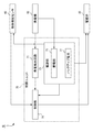
- FIG. 2 is a functional block diagram showing the configuration of the water supply control device 10 according to the first embodiment.
- the control unit 70 controls the operation of the electromagnetic valve 20 and the sensor 60.
- the control unit 70 includes a power generation detection circuit 71 (power generation detection unit), a power source unit 73, and a control unit 79.
- the power generation detection circuit 71 detects the presence or absence of power generation by the generator 50.
- the power generation detection circuit 71 outputs a signal to the control unit 79 when there is power generation by the power generator 50, and does not output a signal to the control unit 79 when there is no power generation by the power generator 50.
- the power generation detection circuit 71 is configured by a shaping circuit that shapes the output waveform from the rectifier circuit that rectifies the alternating current output from the generator 50 into a rectangular wave and outputs the rectangular wave to the control unit 79.
- the power supply unit 73 supplies power to the control unit 79, the sensor 60, and the electromagnetic valve 20.
- the power supply unit 73 includes a power storage unit 75 and a backup battery 77.
- the power storage unit 75 is a capacitor, but may be configured by a secondary battery or the like.
- the power storage unit 75 stores a current obtained by rectifying an alternating current output from the generator 50 by a full-wave rectifier circuit or the like.
- the control unit 79, the sensor 60, and the electromagnetic valve 20 are driven using the power storage unit 75 as a main power source.
- the backup battery 77 is a dry battery, but is not limited to this.
- the backup battery 77 supplies electric power when the voltage of the power storage unit 75 becomes equal to or lower than a predetermined voltage, and drives the control unit 79, the sensor 60, and the electromagnetic valve 20.
- the control unit 79 is composed of a microcomputer.
- the control unit 79 outputs a control signal to the electromagnetic valve 20 based on the output signal from the sensor 60 and controls the opening and closing of the electromagnetic valve 20.
- the control unit 79 may be realized by combining elements and circuits including a computer CPU and memory.
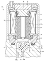
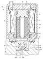
- the solenoid valve 20 is a latch type solenoid valve.
- the electromagnetic valve 20 includes a moving body 26, a permanent magnet 27, a fixed core 29, a coil 31, a spring 33 (biasing member), a ring body 35, and a housing 37.
- the latch electromagnetic valve moves the moving body 26 by energizing the coil 31, opens and closes the water supply passage 107 by opening and closing the valve portion 21 by moving the moving body 26, and magnetizes the permanent magnet 27.
- the movable body 26 is configured to be held in the valve opening position or the valve closing position by the fixed core 29 or the spring 33.
- the moving body 26 includes a plunger 23 and a valve body 25.
- the plunger 23 is held in an accommodating portion 37 a provided in the housing 37 so as to be capable of reciprocating in the axial direction.
- the valve body 25 is provided at the tip of the plunger 23.
- a valve chamber 109 is provided in the middle of the water supply passage 107, and the valve body 25 is disposed in the valve chamber 109.
- an inflow port 109a connected to the upstream side of the water supply channel 107 and an outflow port 109b connected to the downstream side of the water supply channel 107 are formed, and a valve seat 111 is provided at the peripheral portion of the outflow port 109b.
- the valve body 25 contacts and separates from the valve seat 111 to open and close the valve portion 21.
- the valve body 25 is provided with an elastic portion 25a formed of an elastic member such as rubber at a position where the valve body 25 is in contact with and separated from the valve seat 111.
- the permanent magnet 27 is arranged coaxially with the plunger 23.
- the fixed core 29 is disposed between the permanent magnet 27 and the plunger 23.
- the fixed core 29 is magnetized by the permanent magnet 27 and attracts the plunger 23 by its attractive force.
- the coil 31 is disposed so as to surround the plunger 23.
- the spring 33 is interposed between the fixed core 29 and the plunger 23, and biases the plunger 23 in the valve closing direction (downward direction in FIG. 3).
- the ring body 35 is disposed below the coil 31.
- the housing 37 is formed in a cup shape and houses the plunger 23 and the like.
- the plunger 23 is attracted to the fixed core 29 by the magnetic force of the permanent magnet 27 and is held in the valve opening position.
- the movable body 26 is held in the closed position by the urging force of the spring 33 when the elastic portion 26 a of the valve body 25 is in the closed position where it contacts the valve seat 111.
- the water supply channel 107 is opened when the moving body 26 is in the valve opening position, and is closed when the moving body 26 is in the valve closing position.
- the coil 31 In moving the moving body 26 of the electromagnetic valve 20 from the valve-opening position to the valve-closing position, the coil 31 generates a magnetic flux in a direction opposite to the flow direction of the magnetic flux flowing in the magnetic path (hereinafter referred to as the forward direction A). Energize to. As a result, the suction force of the fixed core 29 with respect to the plunger 23 is weakened, and the urging force of the spring 33 becomes larger than this suction force. The urging force moves the moving body 26 from the valve opening position and stops at the valve closing position.
- the moving body 26 moves from the valve closing position by this suction force and stops at the valve opening position.
- the attractive force of the fixed core 29 becomes strong, and even if the energization to the coil 31 is stopped, the attractive force of the fixed core 29 remains larger than the urging force of the spring 33.
- the moving body 26 is stably held at the valve opening position.
- the moving body 26 of the electromagnetic valve 20 is stably held at the two positions of the valve closing position or the valve opening position.
- the control unit 79 In moving the moving body 26 from the valve opening position to the valve closing position, the control unit 79 outputs a valve closing signal as a control signal for closing the electromagnetic valve 20.
- the solenoid valve 20 When receiving the valve closing signal, the solenoid valve 20 energizes the coil 31 so that a magnetic flux of a flow in the positive direction A is generated.
- the control unit 79 outputs a valve opening signal as a control signal for opening the electromagnetic valve 20.
- the solenoid valve 20 receives the valve opening signal, it energizes the coil 31 so that a magnetic flux in a direction opposite to the forward direction A is generated.
- the electromagnetic valve 20 is subjected to a force for moving the moving body 26 from the valve closing position to the valve opening position while the valve opening signal is output. Further, the solenoid valve 20 is subjected to a force for moving the moving body 26 from the valve opening position to the valve closing position while the valve closing signal is output. This force refers to the suction force of the fixed core 29 and the biasing force of the spring 33.
- the moving speed of the moving body 26 becomes slow due to the biting of foreign matter between the moving body 26 and the accommodating portion 37a or the elastic portion 25a of the moving body 26, adhesion, or adhesion of scale.
- the output of the control signal stops before 26 completely stops at the planned stop position.
- the moving body 26 if the moving body 26 continues to move due to inertia and the speed immediately after the stop of the output of the control signal is slow, the moving body 26 is pressed against the planned stop position by the suction force of the fixed core 29 and the biasing force of the spring 33, and the planned stop position. Stop completely.
- the moving body 26 tries to stabilize at the two positions of the valve opening position or the valve closing position, and therefore bounces due to the collision with the valve seat 111 or the fixed core 29, It was found that there was a case where the planned stop position was moved away to the movement start position by the momentum and stopped at the movement start position.
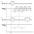
- FIG. 5A is a time chart showing the output of the power generation detection circuit 71 when there is no abnormality in the closing operation of the electromagnetic valve 20.
- the electromagnetic valve 20 is in an open state until time a1, and water is supplied from the electromagnetic valve 20 to the downstream side of the water supply passage 107, and water is discharged from the water outlet 105.
- the generator 50 generates power, and a rectangular pulse signal is output from the power generation detection circuit 71 to the control unit 79.
- the control unit 79 outputs a first valve closing signal of a predetermined output time Ta1 (s) to the electromagnetic valve 20 at time a1.
- the control unit 79 generates power by the generator 50 by the power generation detection circuit 71 within a predetermined detection time ta2 (s) after a predetermined standby time ta1 (s) has elapsed from the start of output of the first valve closing signal. It is determined whether or not is detected. In the illustrated example, the generator 50 does not generate power within the detection time ta ⁇ b> 2, and no pulse signal is output from the power generation detection circuit 71. In this case, the electromagnetic valve 20 is in a closed state, and it can be grasped that the water stoppage to the water discharge port 105 has been completed. Therefore, the control unit 79 does not perform any particular process.
- the generator 50 generates power within the detection time ta2, and a pulse signal is output from the power generation detection circuit 71.
- the electromagnetic valve 20 is in the open state, the generator 50 generates power, and the water stoppage to the water outlet 105 is not completed.
- the control unit 79 outputs the second valve closing signal of the output time Ta2 (s) longer than the output time Ta1 of the first valve closing signal to the electromagnetic valve 20 after the elapse of the detection time ta2.
- the force which moves the mobile body 26 to a valve closing position acts for a time longer than the time of the output of a 1st valve closing signal.
- the output of the first valve closing signal is stopped before the moving body 26 completely stops at the valve closing position when the first valve closing signal is output, and the moving body 26 continues to move due to inertia, Consider the case of bouncing from the valve closing position and returning to the valve opening position.
- the second valve closing signal is output, it is easy to push the bounding moving body 26 back to the valve closing position, and it is possible to effectively suppress the occurrence of an operation failure when the valve is closed.
- the output time Ta2 is only required to be longer than the output time Ta1 of the first valve closing signal, and the range thereof is not limited.
- the lower limit value may be two times or more of the output time Ta1.
- This lower limit is a value derived from experimental knowledge. The inventor studied the phenomenon in which the moving body 26 bounces from the planned stop position and returns to the movement start position. As a result, if the output time Ta2 of the second valve closing signal is set to be twice or more the output time Ta1 of the first valve closing signal, the moving body 26 is effectively stopped at the planned stop position without returning to the movement start position. And gained knowledge. Note that if the output time Ta2 is too long, the power consumption becomes excessive. Therefore, the required length may be set as the upper limit value in consideration of the power consumption.
- the standby time ta1 is set as a time that is assumed in design as the time from when the moving body 26 completely stops at the valve closing position after the first valve closing signal is output until the power generation by the generator 50 stops. .
- a time that is assumed in terms of design is set as a time required to detect this by the power generation detection circuit 71.
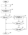
- FIG. 6 is a flowchart for explaining the flow of the valve closing control process of the electromagnetic valve 20 executed by the control unit 79 of the water supply control device 10.
- the flow after the electromagnetic valve 20 is opened under the control of the control unit 79 and water is discharged from the water outlet 105 will be described.
- control part 79 acquires the detection signal which shows that a to-be-detected object does not exist in a detection area from the sensor 60 while the water discharge port 105 is discharging water (S10), it will output the 1st valve closing signal of output time Ta1. It outputs to the solenoid valve 20 (S12).
- the control unit 79 determines whether or not power generation by the power generator 50 is detected by the power generation detection circuit 71 within the detection time ta2 after the elapse of the standby time ta1 from the output start of the first valve closing signal (S14). If the control unit 79 does not acquire a pulse signal from the power generation detection circuit 71 (N in S14), the control unit 79 determines that the water stop of the water outlet 105 has been completed, and ends this flow (S16). On the other hand, when acquiring the pulse signal from the power generation detection circuit 71 (Y in S14), the control unit 79 outputs the second valve closing signal of the output time Ta2 to the electromagnetic valve 20 after the detection time ta2 has elapsed (S18).
- the control unit 79 determines whether or not power generation by the generator 50 is detected by the power generation detection circuit 71 within the detection time ta2 after the elapse of the standby time ta1 from the output start of the second valve closing signal (S20). If the control unit 79 does not acquire a pulse signal from the power generation detection circuit 71 (N in S20), the control unit 79 determines that the water stop of the water outlet 105 has been completed, and ends this flow (S16). On the other hand, if the control part 79 acquires a pulse signal from the electric power generation detection circuit 71 (Y of S20), it will determine whether the frequency
- the control unit 79 When it is determined that the number of times of output of the second valve closing signal is not the second time (N in S22), the control unit 79 outputs the second valve closing signal of the output time Ta2 to the solenoid valve 20 again after the detection time ta2 has elapsed. (S18). On the other hand, when it is determined that the number of times the second valve closing signal is output is the second time (Y in S22), the control unit 79 determines that an operation failure has occurred in the electromagnetic valve 20, and ends this flow (S16). ). In S22, it is determined whether or not the number of outputs of the second valve closing signal is the second time, but the number of times is not particularly limited as long as it can be determined whether or not the number of outputs is a predetermined number.
- the output times Ta1 and Ta2 are stored in advance in a recording unit (not shown) of the control unit 79, and the control unit 79 reads out from the recording unit and acquires them.
- FIG. 7A is a time chart showing the output of the power generation detection circuit 71 when there is no abnormality in the opening operation of the electromagnetic valve 20.
- the electromagnetic valve 20 is in a closed state until time b1, and the downstream side of the water supply passage 107 is stopped from the electromagnetic valve 20 and water is not discharged from the water outlet 105. At this time, the generator 50 does not generate power, and no pulse signal is output from the power generation detection circuit 71 to the control unit 79.
- the control unit 79 outputs a first valve opening signal for a predetermined output time Tb1 (s) to the electromagnetic valve 20 at time b1.
- the controller 79 generates power by the generator 50 by the power generation detection circuit 71 within a predetermined detection time tb2 (s) after the elapse of a predetermined standby time tb1 (s) from the output start of the second valve opening signal. It is determined whether or not is detected.
- the generator 50 is generating power within the detection time tb2, and a pulse signal is output from the power generation detection circuit 71.
- the control unit 79 since the solenoid valve 20 is in the open state and it can be grasped that the water discharge to the water discharge port 105 is completed, the control unit 79 does not particularly perform the process.
- FIG. 7B shows that the generator 50 is not generating power within the detection time tb2, and the pulse signal is not output from the power generation detection circuit 71.
- the electromagnetic valve 20 is in a closed state and the water discharge to the water discharge port 105 is not completed.
- the control unit 79 outputs a second valve closing signal having an output time Tb2 (s) longer than the output time Tb1 of the first valve opening signal to the electromagnetic valve 20.
- the force which moves the mobile body 26 to a valve-opening position acts over a longer time than when the first valve-opening signal is output.
- the output of the first valve opening signal stops before the moving body 26 completely stops at the valve opening position when the first valve opening signal is output, and the moving body 26 continues to move due to inertia, Consider the case of bouncing from the valve opening position and returning to the valve closing position.
- the bound moving body 26 can be easily pushed back to the valve opening position, and the occurrence of an operation failure at the time of valve opening can be effectively suppressed.
- this output time Tb2 may be longer than the output time Tb1 of the first valve opening signal, and the range thereof is not limited. It is good also as 2 times or more of Tb1. The reason is the same as the output time Ta2 of the second valve closing signal.
- the standby time tb1 is set as a time that is assumed in design as the time from when the moving body 26 completely stops at the valve opening position after the first valve closing signal is output and when power generation by the generator 50 starts.
- the detection time tb2 when the generator 50 is generating power after the standby time tb1 has elapsed, a time that is assumed in design is set as a time required to detect this by the power generation detection circuit 71.
- FIG. 8 is a flowchart for explaining the flow of the valve opening control process of the electromagnetic valve 20 executed by the control unit 79 of the water supply control device 10.
- the flow after the electromagnetic valve 20 is closed under the control of the control unit 79 and the water outlet 105 is stopped will be described.
- the control part 79 acquires the detection signal which shows that the to-be-detected object exists in a detection area from the sensor 60 while the water outlet 105 has stopped water (S30), the 1st valve opening signal of output time Tb1 Is output to the solenoid valve 20 (S32).
- the control unit 79 determines whether or not power generation by the power generator 50 is detected by the power generation detection circuit 71 within the detection time tb2 after the elapse of the standby time tb1 from the output start of the first valve opening signal (S34). If the control part 79 acquires a pulse signal from the electric power generation detection circuit 71 (Y of S34), it will judge that the water discharge to the water discharge port 105 was completed, and will complete
- the control unit 79 determines whether or not power generation by the power generator 50 is detected by the power generation detection circuit 71 within the detection time tb2 after the elapse of the standby time tb1 from the output start of the second valve opening signal (S40). If the control part 79 acquires a pulse signal from the electric power generation detection circuit 71 (Y of S40), it will judge that the water discharge to the water discharge port 105 was completed, and will complete
- the control unit 79 When it is determined that the number of times the second valve opening signal is output is not the second time (N in S42), the control unit 79 outputs the second valve opening signal at the output time Tb2 to the solenoid valve 20 again after the detection time tb2 has elapsed. (S38). On the other hand, when it is determined that the number of times the second valve opening signal is output is the second time (Y in S42), the control unit 79 determines that an operation failure has occurred in the electromagnetic valve 20, and ends this flow (S36). ).
- the occurrence of the opening / closing operation failure of the electromagnetic valve 20 can be suppressed.
- the output time of the control signal is usually set to be short so as to approach the minimum necessary time until the moving body 26 is moved from the movement start position to the planned stop position and stopped in order to reduce power consumption. .
- the water supply control device 10 may be used for a urinal, a urinal, and the like.
- the solenoid valve 20 is not limited to a latch type solenoid valve, and may be a continuous energization type solenoid valve.
- the generator 50 only needs to be able to generate power with the water flow in the water supply channel 107, and a known structure for the power generation may be used.
- the mounting position of the sensor 60 is not limited to the water discharge pipe 101. Moreover, the sensor 60 should just detect whether the to-be-detected object exists in a predetermined detection area, and the other well-known detection system for that may be used.
- the power generation detection circuit 71 is exemplified as a power generation detection unit that detects the presence or absence of power generation by the generator 50.
- the power generation detection unit only needs to detect the presence or absence of power generation by the power generator 50 and output a signal to the control unit 79 when power is generated by the power generator 50.
- the power generation detection unit detects the rotation of the water turbine of the power generator 50. You may comprise by a rotation sensor etc.
- the water supply control device 10 may include an error notification unit that notifies the user of the occurrence of the opening / closing failure of the solenoid valve 20.
- the error notification unit includes a light emitting unit such as an LED and a display unit such as a liquid crystal display.
- the error notification unit notifies the user of this by turning on the light emitting unit or displaying the display unit.
- the control unit 79 notifies the user of the occurrence of the opening / closing failure of the electromagnetic valve 20 by controlling the error notification unit. Good. The same applies when it is determined in S42 described above that the number of outputs of the second valve opening signal is a predetermined number.
- the present invention can be applied to the field related to a water supply control device.
Landscapes
- Engineering & Computer Science (AREA)
- General Engineering & Computer Science (AREA)
- Mechanical Engineering (AREA)
- Physics & Mathematics (AREA)
- Electromagnetism (AREA)
- Domestic Plumbing Installations (AREA)
- Magnetically Actuated Valves (AREA)
Abstract
給水路に設置される電磁弁と、給水路内の水流により発電する発電機と、発電機による発電の有無を検出する発電検出部と、電磁弁に制御信号を出力し、電磁弁の開閉を制御する制御部と、を備える。制御部は、電磁弁を閉弁させる第1閉弁信号の出力後、予め定められた時間内に発電機による発電が検出された場合、第1閉弁信号より出力時間の長い第2閉弁信号を出力する。
Description
本発明は、自動水栓等に用いられる給水制御装置に関する。
キッチン、洗面台等では自動水栓が広く用いられる。この自動水栓では、通常、吐水口につながる給水路に設置される電磁弁と、電磁弁に制御信号を出力し、電磁弁の開閉を制御する制御部を備える給水制御装置が用いられる。制御部による制御のもと、電磁弁が給水路を開閉し、吐水口への給水、止水が切り替えられる。
この自動水栓では、電磁弁への異物の噛み込み等により、制御部から開弁信号や閉弁信号を出力しても電磁弁が開弁又は閉弁しない場合がある。この電磁弁の開閉動作不良の発生を抑えるため、特許文献1の技術では、給水路に発電機を設置している。電磁弁に開弁信号や閉弁信号を出力後、発電機による発電の有無を検出し、電磁弁が開弁又は閉弁していないと検知した場合、開弁信号又は閉弁信号を再出力し、電磁弁が開閉するように制御する。
本発明者が検討したところ、特許文献1の技術のように開弁信号や閉弁信号を再出力したのみでは、電磁弁の開閉動作不良の発生を抑えられない場合があるとの知見を得た。
本発明は、このような課題に鑑みてなされ、その目的は、電磁弁の開閉動作不良の発生を効果的に抑えられる技術を提供することにある。
上述の課題を解決するために、本発明のある態様は、給水制御装置に関する。給水制御装置は、給水路に設置される電磁弁と、給水路内の水流により発電する発電機と、発電機による発電の有無を検出する発電検出部と、電磁弁に制御信号を出力し、電磁弁の開閉を制御する制御部と、を備え、制御部は、電磁弁を閉弁させる第1閉弁信号の出力後、予め定められた時間内に発電機による発電が検出された場合、第1閉弁信号より出力時間の長い第2閉弁信号を出力する。
この態様によれば、第1閉弁信号より出力時間の長い第2閉弁信号を電磁弁に出力することにより、電磁弁の弁部を開閉する移動体に対して、第1閉弁信号の出力時より長い時間に亘り閉弁位置に移動させる力が作用する。第1閉弁信号の出力時に移動体が閉弁位置で完全に停止する前に第1閉弁信号の出力が停止し、慣性により移動体が移動し続け、移動体が閉弁位置からバウンドして開弁位置まで戻る場合を考える。この場合でも、第2閉弁信号の出力時にはバウンドした移動体を閉弁位置まで押し戻し易くなり、閉弁時の動作不良の発生を効果的に抑えられる。
また、本発明の別の態様に係る給水制御装置は、給水路に設置される電磁弁と、給水路内の水流により発電する発電機と、発電機による発電の有無を検出する発電検出部と、電磁弁に制御信号を出力し、電磁弁の開閉を制御する制御部と、を備え、制御部は、電磁弁を開弁させる第1開弁信号の出力後、予め定められた時間内に発電機による発電が検出されなかった場合、第1開弁信号より出力時間の長い第2開弁信号を出力する。
この態様によれば、第1開弁信号より出力時間の長い第2開弁信号を電磁弁に出力することにより、電磁弁の弁部を開閉する移動体に対して、第1開弁信号の出力時より長い時間に亘り開弁位置に移動させる力が作用する。第1開弁信号の出力時に移動体が開弁位置で完全に停止する前に第1開弁信号の出力が停止し、慣性により移動体が移動し続け、移動体が開弁位置からバウンドして閉弁位置まで戻る場合を考える。この場合でも、第2開弁信号の出力時にはバウンドした移動体を開弁位置まで押し戻し易くなり、開弁時の動作不良の発生を効果的に抑えられる。
本発明によれば、電磁弁の開閉動作不良の発生を効果的に抑えられる。
[第1の実施の形態]
図1は第1実施形態に係る給水制御装置10が用いられる自動水栓100の構成図を示す。自動水栓100は、吐水管101と、給水制御装置10を備える。
図1は第1実施形態に係る給水制御装置10が用いられる自動水栓100の構成図を示す。自動水栓100は、吐水管101と、給水制御装置10を備える。
吐水管101は、洗面台のカウンター103の上面側に固定される。吐水管101は、その先端部に吐水口105が設けられる。吐水口105からは、これに給水するための給水路107を通して給水される水が吐き出される。給水路107は、上水道108から吐水口105にかけて設けられ、給水ホース等の内側に設けられる。
給水制御装置10は、吐水口105への給水及び止水を制御する。給水制御装置10は、電磁弁20と、発電機50と、物体検知センサ60(以下、単にセンサ60ともいう)と、制御ユニット70を備える。
電磁弁20は、給水路107の途中位置に設置される。電磁弁20は、後述のように、給水路107の下流側への給水及び止水を切り替え、吐水口105からの吐水の有無を切り替えるように制御部79(後述する)により制御される。
発電機50は、給水路107において電磁弁20の下流側に設置される。発電機50は、給水路107に設置される水車を有し、その水車の羽根に給水路107を流れる水の水流が当たることにより水車が回転し、その回転により発電する。発電機50は、水車の回転により磁石とコイルを相対回転させ、電磁誘導によりコイルが発電するように構成される。
センサ60は、発光部と受光部を有する赤外線式測距センサである。センサ60は、吐水管101の先端部に取り付けられる。センサ60は、発光部から光を投光し、投光した光による人体の手等の被検知物からの反射光を受光部で受光し、センサ60に対して所定の範囲内にある検知エリア内に被検知物が有るか否かを検知する。センサ60は、被検知物の検知結果を示す信号を制御部79(後述する)に出力する。
図2は第1実施形態に係る給水制御装置10の構成を示す機能ブロック図である。制御ユニット70は、電磁弁20やセンサ60の動作を制御する。制御ユニット70は、発電検出回路71(発電検出部)と、電源部73と、制御部79を備える。
発電検出回路71は、発電機50による発電の有無を検出する。発電検出回路71は、発電機50による発電が有る場合、制御部79に信号を出力し、発電機50による発電が無い場合、制御部79に信号を出力しない。発電検出回路71は、発電機50から出力される交流電流を整流する整流回路からの出力波形を矩形波に整形して制御部79に出力する整形回路により構成される。
電源部73は、制御部79、センサ60、電磁弁20に電力を供給する。電源部73は、蓄電部75と、バックアップ電池77を備える。蓄電部75は、コンデンサであるが、二次電池等により構成されてもよい。蓄電部75には、発電機50から出力される交流電流を全波整流回路等により整流した電流が蓄電される。制御部79、センサ60、電磁弁20は、蓄電部75を主電源として駆動する。バックアップ電池77は、乾電池であるが、これに限定されない。バックアップ電池77は、蓄電部75の電圧が所定の電圧以下になったときに電力を供給し、制御部79、センサ60、電磁弁20を駆動させる。
制御部79は、マイクロコンピュータにより構成される。制御部79は、センサ60からの出力信号に基づき電磁弁20に制御信号を出力し、電磁弁20の開閉を制御する。なお、制御部79は、コンピュータのCPU、メモリをはじめとする素子や回路を組み合わせて実現されていればよい。
図3は電磁弁20の弁部21が開いている状態を示し、図4は弁部21が閉じている状態を示す。電磁弁20は、ラッチ式電磁弁である。電磁弁20は、移動体26と、永久磁石27と、固定コア29と、コイル31と、ばね33(付勢部材)と、リング体35と、ハウジング37を備える。ラッチ式電磁弁は、詳述するように、コイル31への通電により移動体26を移動させ、移動体26の移動により弁部21を開閉して給水路107を開閉し、永久磁石27に磁化された固定コア29又はばね33により移動体26を開弁位置又は閉弁位置に保持するように構成される。
移動体26は、プランジャ23と、弁体25を含む。プランジャ23は、ハウジング37内に設けられる収容部37a内に軸方向に往復動自在に保持される。弁体25は、プランジャ23の先端部に設けられる。給水路107の途中位置には弁室109が設けられ、その弁室109内に弁体25が配置される。弁室109には、給水路107の上流側につながる流入口109aと、給水路107の下流側につながる流出口109bとが形成され、流出口109bの周縁部には弁座111が設けられる。弁体25は、弁座111と接触離間して弁部21を開閉する。弁体25は、弁座111と接触離間する箇所にゴム等の弾性部材により形成される弾性部25aが設けられる。
永久磁石27は、プランジャ23と同軸上に配置される。固定コア29は、永久磁石27とプランジャ23の間に配置される。固定コア29は、永久磁石27により磁化され、その吸引力によりプランジャ23を吸着する。コイル31はプランジャ23を囲むように配置される。ばね33は固定コア29とプランジャ23の間に介装され、プランジャ23を閉弁方向(図3の下方向)に付勢する。リング体35は、コイル31より下側に配置される。ハウジング37は、カップ状に形成され、プランジャ23等を収容する。
移動体26は、固定コア29とプランジャ23が接触する開弁位置にあるとき、永久磁石27による磁力により固定コア29にプランジャ23が吸着され、その開弁位置に保持される。一方、移動体26は、弁体25の弾性部26aが弁座111と接触する閉弁位置にあるとき、ばね33の付勢力によりその閉弁位置に保持される。給水路107は、移動体26が開弁位置にあるときに開かれ、移動体26が閉弁位置にあるときに閉じられる。
この電磁弁20では、コイル31に通電しないとき、永久磁石27から固定コア29、プランジャ23、リング体35、ハウジング37を通して永久磁石27に戻る磁路が形成される。
電磁弁20の移動体26を開弁位置から閉弁位置に移動させるうえでは、磁路を流れる磁束の流れ方向と逆方向(以下、正方向Aという)の流れの磁束が生じるようにコイル31に通電する。これにより、プランジャ23に対する固定コア29の吸引力が弱まり、ばね33の付勢力がこの吸引力より大きくなり、この付勢力により移動体26が開弁位置から移動し、閉弁位置で停止する。このとき、プランジャ23と固定コア29の距離が大きいため固定コア29の吸引力が弱くなり、コイル31への通電を停止しても、固定コア29の吸引力よりもばね33の付勢力が大きいままとなり、移動体26が閉弁位置に安定して保持される。
一方、正方向Aと反対方向の流れの磁束が生じるようにコイル31に通電すると、プランジャ23に対する固定コア29の吸引力が強まり、ばね33の付勢力より固定コア29の吸引力が大きくなる。移動体26は、この吸引力により閉弁位置から移動し、開弁位置で停止する。このとき、プランジャ23と固定コア29の距離が小さいため固定コア29の吸引力が強くなり、コイル31への通電を停止しても、固定コア29の吸引力がばね33の付勢力より大きいままとなり、移動体26が開弁位置に安定して保持される。このように、電磁弁20の移動体26は、閉弁位置か開弁位置の二位置で安定して保持される。
移動体26を開弁位置から閉弁位置に移動させるうえで、制御部79は、電磁弁20を閉弁させるための制御信号として閉弁信号を出力する。電磁弁20は、閉弁信号を受けると、コイル31に正方向Aの流れの磁束が生じるように通電する。一方、移動体26を閉弁位置から開弁位置に移動させるうえで、制御部79は、電磁弁20を開弁させるための制御信号として開弁信号を出力する。電磁弁20は、開弁信号を受けると、コイル31に正方向Aと反対方向の流れの磁束が生じるように通電する。
電磁弁20は、開弁信号が出力されている間、閉弁位置から開弁位置に移動体26を移動させる力が作用する。また、電磁弁20は、閉弁信号が出力されている間、開弁位置から閉弁位置に移動体26を移動させる力が作用する。この力とは、固定コア29の吸引力やばね33の付勢力をいう。
ここで、本発明者は、電磁弁20の開閉を制御するうえで、以下の新たな課題を認識するに至った。
電磁弁20は、移動体26と収容部37aの間や、移動体26の弾性部25aへの異物の噛み込み、付着や、水垢の付着等により移動体26の移動速度が遅くなり、移動体26が停止予定位置で完全に停止する前に制御信号の出力が停止する場合が生じる。この場合、移動体26は、慣性により移動し続け、制御信号の出力停止直後の速度が遅ければ、固定コア29の吸引力やバネ33の付勢力により停止予定位置に押さえ付けられ、停止予定位置で完全に停止する。しかし、移動体26は、制御信号の出力停止直後の速度が速い場合、開弁位置又は閉弁位置の二位置で安定しようとするため、弁座111や固定コア29との衝突によりバウンドし、その勢いにより停止予定位置を離れて移動開始位置まで戻り、移動開始位置で停止する場合があるとの知見を得た。
この場合、特許文献1に記載の技術では、電磁弁が開弁又は閉弁していないとして検知され、最初の開弁信号や閉弁信号と同じ出力時間の開弁信号や閉弁信号を再出力している。しかし、移動体26の一部や他部材との間に異物が噛み込まれたままであると、移動体26の移動速度が遅いままとなり、そのような同じ出力時間の制御信号を出力しても同じ動作が繰り返され、電磁弁20の開閉動作不良の発生を十分に抑えられなかった。
そこで、本実施形態に係る給水制御装置10では、以下のような制御を実行している。まず、電磁弁20の閉弁動作不良の発生を抑えるための制御方法から説明する。図5(a)は、電磁弁20の閉弁動作に異常がないときの発電検出回路71の出力を示すタイムチャートである。
電磁弁20は、時刻a1までの間、開弁状態になっており、電磁弁20より給水路107の下流側へ給水され、吐水口105から水が吐き出される。このとき、発電機50が発電し、発電検出回路71から矩形状のパルス信号が制御部79に出力される。制御部79は、時刻a1において、予め定められた出力時間Ta1(s)の第1閉弁信号を電磁弁20に出力する。
制御部79は、第1閉弁信号の出力開始から予め定められた待機時間ta1(s)の経過後、予め定められた検出時間ta2(s)内に発電検出回路71により発電機50による発電が検出されるか否か判定する。図示の例では、検出時間ta2内に発電機50が発電しておらず、発電検出回路71からパルス信号が出力されていないことを示す。この場合、電磁弁20が閉弁状態になっており、吐水口105への止水が完了したことを把握できるため、制御部79は、特に処理を実行しない。
一方、図5(b)の例では、検出時間ta2内に発電機50が発電しており、発電検出回路71からパルス信号が出力されている。この場合、電磁弁20が開弁状態になっており、発電機50が発電し、吐水口105への止水が完了していないことを把握できる。
この場合、本実施形態に係る制御部79は、検出時間ta2の経過後、第1閉弁信号の出力時間Ta1よりも長い出力時間Ta2(s)の第2閉弁信号を電磁弁20に出力する。これにより、第1閉弁信号の出力時より長い時間に亘り移動体26を閉弁位置に移動させる力が作用する。ここで、第1閉弁信号の出力時に移動体26が閉弁位置で完全に停止する前に第1閉弁信号の出力が停止し、移動体26が慣性により移動し続け、移動体26が閉弁位置からバウンドして開弁位置まで戻る場合を考える。この場合でも、第2閉弁信号の出力時にはバウンドした移動体26を閉弁位置まで押し戻し易くなり、閉弁時の動作不良の発生を効果的に抑えられる。
この出力時間Ta2は、第1閉弁信号の出力時間Ta1より長ければよく、その範囲について限定するものではないが、その下限値として、出力時間Ta1の2倍以上としてもよい。この下限値は実験的な知見により導出された値である。本発明者は、上述のような移動体26が停止予定位置からバウンドし移動開始位置まで戻る現象を検討した。この結果、第2閉弁信号の出力時間Ta2を第1閉弁信号の出力時間Ta1の2倍以上とすれば、移動体26が移動開始位置まで戻らず停止予定位置で効果的に停止させられるとの知見を得た。なお、出力時間Ta2は、長すぎると消費電力が過多になるため、消費電力を考慮したうえで必要な長さを上限値に定めてもよい。
なお、待機時間ta1は、第1閉弁信号の出力後に移動体26が閉弁位置に完全に停止し、発電機50による発電が停止するまでの時間として設計上想定される時間が設定される。検出時間ta2は、待機時間ta1の経過後、発電機50が発電している場合、そのことを発電検出回路71により検出するために必要な時間として設計上想定される時間が設定される。
図6は、給水制御装置10の制御部79が実行する電磁弁20の閉弁制御処理の流れを説明するフローチャートである。ここでは、制御部79による制御のもとで電磁弁20を開弁させて、吐水口105から吐水してからの流れを説明する。
制御部79は、吐水口105が吐水している間(S10)、検知エリア内に被検知物が存在しない旨を示す検出信号をセンサ60から取得したら、出力時間Ta1の第1閉弁信号を電磁弁20に出力する(S12)。
制御部79は、第1閉弁信号の出力開始から待機時間ta1の経過後、検出時間ta2内に発電検出回路71により発電機50による発電が検出されるか否か判定する(S14)。制御部79は、発電検出回路71からパルス信号を取得しなければ(S14のN)、吐水口105の止水が完了したと判断し、本フローを終了する(S16)。一方、制御部79は、発電検出回路71からパルス信号を取得したら(S14のY)、検出時間ta2の経過後、出力時間Ta2の第2閉弁信号を電磁弁20に出力する(S18)。
制御部79は、第2閉弁信号の出力開始から待機時間ta1の経過後、検出時間ta2内に発電検出回路71により発電機50による発電が検出されるか否か判定する(S20)。制御部79は、発電検出回路71からパルス信号を取得しなければ(S20のN)、吐水口105の止水が完了したと判断し、本フローを終了する(S16)。一方、制御部79は、発電検出回路71からパルス信号を取得したら(S20のY)、第2閉弁信号の出力回数が2回目か否かを判定する(S22)。
第2閉弁信号の出力回数が2回目でないと判定した場合(S22のN)、制御部79は、検出時間ta2の経過後、出力時間Ta2の第2閉弁信号を電磁弁20に再度出力する(S18)。一方、第2閉弁信号の出力回数が2回目であると判定した場合(S22のY)、制御部79は、電磁弁20に動作不良が発生したと判断し、本フローを終了する(S16)。なお、S22において、第2閉弁信号の出力回数が2回目であるか否かを判定したが、その出力回数が所定回数か否かを判定できれば、その回数は特に限定されない。
なお、出力時間Ta1、Ta2は、予め制御部79の記録部(図示せず)に記憶されており、制御部79は、その記録部から読み出してこれを取得する。
次に、電磁弁20の開弁動作不良の発生を抑えるための制御方法を説明する。図7(a)は、電磁弁20の開弁動作に異常がないときの発電検出回路71の出力を示すタイムチャートである。
電磁弁20は、時刻b1までの間、閉弁状態になっており、電磁弁20より給水路107の下流側が止水され、吐水口105から吐水されない。このとき、発電機50は発電せず、発電検出回路71からパルス信号が制御部79に出力されない。制御部79は、時刻b1において、予め定められた出力時間Tb1(s)の第1開弁信号を電磁弁20に出力する。
制御部79は、第2開弁信号の出力開始から予め定められた待機時間tb1(s)の経過後、予め定められた検出時間tb2(s)内に発電検出回路71により発電機50による発電が検出されるか否か判定する。図示の例では、検出時間tb2内に発電機50が発電しており、発電検出回路71からパルス信号が出力されていることを示す。この場合、電磁弁20が開弁状態になっており、吐水口105への吐水が完了したと把握できるため、制御部79は、特に処理を実行しない。
一方、図7(b)の例では、検出時間tb2内に発電機50が発電しておらず、発電検出回路71からパルス信号が出力されないことを示す。この場合、電磁弁20が閉弁状態になっており、吐水口105への吐水が完了していないと把握できる。
この場合、本実施形態に係る制御部79は、検出時間tb2の経過後、第1開弁信号の出力時間Tb1よりも長い出力時間Tb2(s)の第2閉弁信号を電磁弁20に出力する。これにより、第1開弁信号を出力したときより長い時間に亘り移動体26を開弁位置に移動させる力が作用する。ここで、第1開弁信号の出力時に移動体26が開弁位置で完全に停止する前に第1開弁信号の出力が停止し、移動体26が慣性により移動し続け、移動体26が開弁位置からバウンドして閉弁位置まで戻る場合を考える。この場合でも、第2開弁信号の出力時にはバウンドした移動体26を開弁位置まで押し戻し易くなり、開弁時の動作不良の発生を効果的に抑えられる。
この出力時間Tb2も、第2閉弁信号の出力時間Ta2と同様に、第1開弁信号の出力時間Tb1より長ければよく、その範囲について限定するものではないが、その下限値として、出力時間Tb1の2倍以上としてもよい。この理由は、第2閉弁信号の出力時間Ta2と同様である。
なお、待機時間tb1は、第1閉弁信号の出力後に移動体26が開弁位置に完全に停止し、発電機50による発電が開始するまでの時間として設計上想定される時間が設定される。検出時間tb2は、待機時間tb1の経過後、発電機50が発電している場合、そのことを発電検出回路71により検出するために必要な時間として設計上想定される時間が設定される。
図8は、給水制御装置10の制御部79が実行する電磁弁20の開弁制御処理の流れを説明するフローチャートである。ここでは、制御部79による制御のもとで電磁弁20を閉弁させて、吐水口105が止水されてからの流れを説明する。
制御部79は、吐水口105が止水している間(S30)、検知エリア内に被検知物が存在する旨を示す検出信号をセンサ60から取得したら、出力時間Tb1の第1開弁信号を電磁弁20に出力する(S32)。
制御部79は、第1開弁信号の出力開始から待機時間tb1の経過後、検出時間tb2内に発電検出回路71により発電機50による発電が検出されるか否か判定する(S34)。制御部79は、発電検出回路71からパルス信号を取得したら(S34のY)、吐水口105への吐水が完了したと判断し、本フローを終了する(S36)。一方、制御部79は、発電検出回路71からパルス信号を取得しなければ(S34のN)、検出時間tb2の経過後、出力時間Tb2の第2開弁信号を電磁弁20に出力する(S38)。
制御部79は、第2開弁信号の出力開始から待機時間tb1の経過後、検出時間tb2内に発電検出回路71により発電機50による発電が検出されるか否か判定する(S40)。制御部79は、発電検出回路71からパルス信号を取得したら(S40のY)、吐水口105への吐水が完了したと判断し、本フローを終了する(S36)。一方、制御部79は、発電検出回路71からパルス信号を取得しなければ(S40のN)、第2開弁信号の出力回数が2回目か否かを判定する(S42)。
第2開弁信号の出力回数が2回目でないと判定した場合(S42のN)、制御部79は、検出時間tb2の経過後、出力時間Tb2の第2開弁信号を電磁弁20に再度出力する(S38)。一方、第2開弁信号の出力回数が2回目であると判定した場合(S42のY)、制御部79は、電磁弁20に動作不良が発生したと判断し、本フローを終了する(S36)。
以上の本実施形態に係る給水制御装置10によれば、電磁弁20の開閉動作不良の発生を抑えられる。
また、電磁弁20の開閉動作不良の発生を抑えるための他の手段として、第1開弁信号や第1閉弁信号を出力する時間間隔を予め長くしておくことも考えられる。しかし、制御信号の出力時間は、通常、消費電力を抑えるために、移動体26を移動開始位置から停止予定位置に移動させて停止するまでに最低限必要な時間に近づくように短く設定される。この点、本実施形態に係る給水制御装置10によれば、第1開弁信号や第1閉弁信号の出力時間を長くしなくともよく、消費電力を抑えつつも、電磁弁20の開閉動作不良の発生を抑えられる。
以上、実施の形態に基づき本発明を説明したが、実施の形態は、本発明の原理、応用を示すにすぎない。また、実施の形態には、請求の範囲に規定された本発明の思想を逸脱しない範囲において、多くの変形例や配置の変更が可能である。
上述の実施形態に係る給水制御装置10は、自動水栓100に用いられる場合を例示した。給水制御装置10は、この他にも、小便器、大便器等に用いられてもよい。
電磁弁20は、ラッチ式電磁弁に限定されず、連続通電式電磁弁でもよい。発電機50は、給水路107内の水流により発電できればよく、その発電のための公知の構造が用いられてもよい。また、センサ60は、その取付位置は吐水管101に限定されない。また、センサ60は、所定の検知エリア内に被検知物が有るか否かを検知できればよく、そのための他の公知の検知方式が用いられてもよい。
上述の実施形態に係る発電検出回路71は、発電機50による発電の有無を検出する発電検出部として例示した。発電検出部は、発電機50による発電の有無を検出し、発電機50による発電がある場合に制御部79に信号を出力できればよく、この他にも、発電機50の水車の回転を検出する回転センサ等により構成されてもよい。
また、給水制御装置10は、電磁弁20の開閉動作不良の発生をユーザーに報知するエラー報知部を備えてもよい。エラー報知部は、LED等の発光部や液晶ディスプレイ等の表示部により構成される。エラー報知部は、電磁弁20に開閉動作不良が発生したとき、発光部の点灯や表示部の表示によりその旨をユーザーに報知する。制御部79は、上述のS22において、第2閉弁信号の出力回数が所定回数であると判定した場合、電磁弁20の開閉動作不良の発生をエラー報知部の制御によりユーザーに報知してもよい。上述のS42において、第2開弁信号の出力回数が所定回数であると判定した場合も同様である。
10 給水制御装置、 20 電磁弁、 50 発電機、 71 発電検出回路(発電検出部)、 79 制御部、 107 給水路。
本発明は、給水制御装置に関する分野に適用できる。
Claims (2)
- 給水路に設置される電磁弁と、
前記給水路内の水流により発電する発電機と、
前記発電機による発電の有無を検出する発電検出部と、
前記電磁弁に制御信号を出力し、前記電磁弁の開閉を制御する制御部と、を備え、
前記制御部は、前記電磁弁を閉弁させる第1閉弁信号の出力後、予め定められた時間内に前記発電検出部により前記発電機による発電が検出された場合、前記第1閉弁信号より出力時間の長い第2閉弁信号を出力することを特徴とする給水制御装置。 - 給水路に設置される電磁弁と、
前記給水路内の水流により発電する発電機と、
前記発電機による発電の有無を検出する発電検出部と、
前記電磁弁に制御信号を出力し、前記電磁弁の開閉を制御する制御部と、を備え、
前記制御部は、前記電磁弁を開弁させる第1開弁信号の出力後、予め定められた時間内に前記発電検出部により前記発電機による発電が検出されなかった場合、前記第1開弁信号より出力時間の長い第2開弁信号を出力することを特徴とする給水制御装置。
Applications Claiming Priority (2)
| Application Number | Priority Date | Filing Date | Title |
|---|---|---|---|
| JP2013259456A JP6282460B2 (ja) | 2013-12-16 | 2013-12-16 | 給水制御装置 |
| JP2013-259456 | 2013-12-16 |
Publications (1)
| Publication Number | Publication Date |
|---|---|
| WO2015093140A1 true WO2015093140A1 (ja) | 2015-06-25 |
Family
ID=53402497
Family Applications (1)
| Application Number | Title | Priority Date | Filing Date |
|---|---|---|---|
| PCT/JP2014/077929 Ceased WO2015093140A1 (ja) | 2013-12-16 | 2014-10-21 | 給水制御装置 |
Country Status (2)
| Country | Link |
|---|---|
| JP (1) | JP6282460B2 (ja) |
| WO (1) | WO2015093140A1 (ja) |
Families Citing this family (1)
| Publication number | Priority date | Publication date | Assignee | Title |
|---|---|---|---|---|
| JP7598559B2 (ja) * | 2020-09-24 | 2024-12-12 | Toto株式会社 | 電磁弁装置及び吐水装置 |
Citations (5)
| Publication number | Priority date | Publication date | Assignee | Title |
|---|---|---|---|---|
| JPH0384282A (ja) * | 1989-08-25 | 1991-04-09 | Inax Corp | 通水路自動開閉弁の駆動方法 |
| JPH0616177Y2 (ja) * | 1988-11-04 | 1994-04-27 | 株式会社イナックス | 水栓の制御装置 |
| JPH06505542A (ja) * | 1991-07-20 | 1994-06-23 | コスモス エントヴィックルングス ウント フォルシュングスアンシュタルト | 衛生設備 |
| JP2005048865A (ja) * | 2003-07-28 | 2005-02-24 | Denso Corp | 電磁弁制御装置 |
| JP2009264490A (ja) * | 2008-04-25 | 2009-11-12 | Toto Ltd | ラッチングソレノイドバルブ |
Family Cites Families (1)
| Publication number | Priority date | Publication date | Assignee | Title |
|---|---|---|---|---|
| JP2002294839A (ja) * | 2001-03-30 | 2002-10-09 | Inax Corp | 給水装置 |
-
2013
- 2013-12-16 JP JP2013259456A patent/JP6282460B2/ja active Active
-
2014
- 2014-10-21 WO PCT/JP2014/077929 patent/WO2015093140A1/ja not_active Ceased
Patent Citations (5)
| Publication number | Priority date | Publication date | Assignee | Title |
|---|---|---|---|---|
| JPH0616177Y2 (ja) * | 1988-11-04 | 1994-04-27 | 株式会社イナックス | 水栓の制御装置 |
| JPH0384282A (ja) * | 1989-08-25 | 1991-04-09 | Inax Corp | 通水路自動開閉弁の駆動方法 |
| JPH06505542A (ja) * | 1991-07-20 | 1994-06-23 | コスモス エントヴィックルングス ウント フォルシュングスアンシュタルト | 衛生設備 |
| JP2005048865A (ja) * | 2003-07-28 | 2005-02-24 | Denso Corp | 電磁弁制御装置 |
| JP2009264490A (ja) * | 2008-04-25 | 2009-11-12 | Toto Ltd | ラッチングソレノイドバルブ |
Also Published As
| Publication number | Publication date |
|---|---|
| JP6282460B2 (ja) | 2018-02-21 |
| JP2015117465A (ja) | 2015-06-25 |
Similar Documents
| Publication | Publication Date | Title |
|---|---|---|
| US5699833A (en) | Electro-mechanical fluid flow control apparatus | |
| RU2014117963A (ru) | Соленоидный привод для переключающего устройства и связанное с ним переключающее устройство | |
| JP6282460B2 (ja) | 給水制御装置 | |
| CN104595552A (zh) | 一种触控水龙头 | |
| JP5185609B2 (ja) | 自己保持型電磁弁における電源ユニット | |
| JP6351380B2 (ja) | 給水制御装置 | |
| JP2013189790A (ja) | 水栓システム | |
| JPH11108232A (ja) | 電磁弁駆動装置 | |
| JP2019176706A5 (ja) | ||
| JP3564906B2 (ja) | ソレノイド駆動装置とこれを用いた弁装置および自動給水装置 | |
| JP5259556B2 (ja) | ガスコンロ | |
| US20180102229A1 (en) | Contactor having electronic coil control | |
| JP6150126B2 (ja) | バルブ装置及び水栓装置 | |
| JPS6323077A (ja) | 自動水栓装置 | |
| RU2549727C1 (ru) | Способ обнаружения протечек воды и устройство для его осуществления | |
| JP7307878B2 (ja) | 電磁弁装置及び吐水装置 | |
| JP7199890B2 (ja) | 自動水栓 | |
| JP7598559B2 (ja) | 電磁弁装置及び吐水装置 | |
| JP2009174599A (ja) | 電磁弁駆動回路の異常検出装置 | |
| JP2695692B2 (ja) | ソレノイドの作動チエツク方法 | |
| JP2017057955A (ja) | 流路開閉装置 | |
| JP7432155B2 (ja) | 水栓装置 | |
| CN106642557A (zh) | 一种水槽放水开关降噪音控制方法、系统及空调 | |
| JPS62292120A (ja) | シヤワ−装置 | |
| JP2011069481A (ja) | バルブ装置およびその駆動方法 |
Legal Events
| Date | Code | Title | Description |
|---|---|---|---|
| 121 | Ep: the epo has been informed by wipo that ep was designated in this application |
Ref document number: 14872802 Country of ref document: EP Kind code of ref document: A1 |
|
| NENP | Non-entry into the national phase |
Ref country code: DE |
|
| 122 | Ep: pct application non-entry in european phase |
Ref document number: 14872802 Country of ref document: EP Kind code of ref document: A1 |