WO2015092887A1 - ブレーキ付きモータ - Google Patents
ブレーキ付きモータ Download PDFInfo
- Publication number
- WO2015092887A1 WO2015092887A1 PCT/JP2013/083957 JP2013083957W WO2015092887A1 WO 2015092887 A1 WO2015092887 A1 WO 2015092887A1 JP 2013083957 W JP2013083957 W JP 2013083957W WO 2015092887 A1 WO2015092887 A1 WO 2015092887A1
- Authority
- WO
- WIPO (PCT)
- Prior art keywords
- brake
- magnetic field
- rotating shaft
- annular portion
- core body
- Prior art date
- Legal status (The legal status is an assumption and is not a legal conclusion. Google has not performed a legal analysis and makes no representation as to the accuracy of the status listed.)
- Ceased
Links
Images






Classifications
-
- H—ELECTRICITY
- H02—GENERATION; CONVERSION OR DISTRIBUTION OF ELECTRIC POWER
- H02K—DYNAMO-ELECTRIC MACHINES
- H02K7/00—Arrangements for handling mechanical energy structurally associated with dynamo-electric machines, e.g. structural association with mechanical driving motors or auxiliary dynamo-electric machines
- H02K7/10—Structural association with clutches, brakes, gears, pulleys or mechanical starters
- H02K7/102—Structural association with clutches, brakes, gears, pulleys or mechanical starters with friction brakes
- H02K7/1021—Magnetically influenced friction brakes
- H02K7/1026—Magnetically influenced friction brakes using stray fields
- H02K7/1028—Magnetically influenced friction brakes using stray fields axially attracting the brake armature in the frontal area of the magnetic core
Definitions
- This disclosure relates to a motor with a brake.
- Patent Document 1 discloses a motor with a brake including a rotor, a stator, and a brake.
- the tip of the rotor protrudes from the stator to the load side (drive target side).
- the base end portion of the rotor protrudes from the stator to the anti-load side (the reverse side of the drive target).
- the brake is provided outside the stator on the side opposite to the load, and applies a braking force to the base end portion of the rotor.
- the present disclosure aims to provide a small motor with a brake.
- a motor with a brake according to the present disclosure is provided in a case so as to surround a rotation shaft, a case that rotatably supports the rotation shaft, and a central axis of the rotation shaft, and generates a magnetic field for rotating the rotation shaft.
- a plurality of driving coils and a brake provided in the case and generating a braking force against the rotating shaft.
- the brake is made of a soft magnetic material and has an annular shape surrounding the central axis of the rotating shaft.
- a core body provided to be stretchable in a direction along the central axis, an annular space formed in the core body over the entire circumference, an elastic member for extending the core body, and the center of the rotating shaft
- a coil for a brake that is wound around an axis and accommodated in an annular space to generate a magnetic field for shortening the core body
- an extension of the core body Has a contact portion that generates a frictional resistance between the rotating shaft and the case in response to the shortening, and at least a part of the core body rotates the rotating shaft and a path of a magnetic field for shortening the core body To be shared with the magnetic field path.
- a small motor with a brake can be provided.
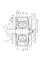
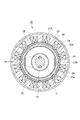
- FIG. 3 is a sectional view taken along line III-III in FIG. 2. It is a side view of a core main body.
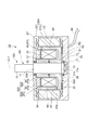
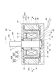
- FIG. 3 is a cross-sectional view showing a state where electric power is supplied to the brake coil in FIG. 2. It is sectional drawing of the motor with a brake concerning 2nd Embodiment. It is sectional drawing which shows the state in which electric power was supplied to the coil for brakes in FIG. It is sectional drawing of the motor with a brake concerning 3rd Embodiment.
- FIG. 9 is a cross-sectional view taken along line IX-IX in FIG.
- the actuator 100 includes a motor 1 with a brake and a speed reducer 110.
- the reducer 110 is attached to the motor 1 with brake in a state where the tip of the rotating shaft 10 of the motor 1 with brake is received.
- the reducer 110 has an output shaft 110a and a plurality of gears (not shown).
- the plurality of gears are built in the speed reducer 110 and transmit the power of the rotary shaft 10 to the output shaft 110a.
- a drive target is attached to the output shaft 110a.
- the actuator 100 is used for driving a robot, for example.
- the motor 1 with a brake includes a rotating shaft 10, a case 20, a stator core 23, a plurality of driving coils 24, a brake 30, an encoder 70, and a cable 80.
- front and rear in the description of each part means a direction in which one end side of the rotating shaft 10 is a front side and the other end side is a rear side.
- the rotary shaft 10 is made of, for example, steel or stainless steel and has a main shaft 11 and extending portions 12 and 13. On the outer periphery of the rear end portion of the main shaft 11, a flange portion 11a is formed over the entire periphery.
- the extension portion 12 is a shaft portion concentric with the main shaft 11, and continues to the front side of the main shaft 11.
- the extension portion 13 is a shaft portion concentric with the main shaft 11, and continues to the rear side of the main shaft 11.
- the extending portions 12 and 13 are smaller in diameter than the main shaft 11.
- Two annular terminals 13 a are provided on the outer periphery of the extending portion 13.
- the two annular terminals 13 a are arranged in a direction along the central axis CL ⁇ b> 1 of the rotating shaft 10, and extend over the entire circumference of the extending portion 13.
- the case 20 has a container 21 and a lid 22 and holds the rotary shaft 10 rotatably.
- the container 21 has a cup shape, and the lid 22 closes the opening of the container 21.
- the container 21 and the lid 22 are made of a nonmagnetic material such as stainless steel, an aluminum alloy, or a resin material.
- a concave portion 21b that opens forward is formed in the central portion of the bottom surface in the container 21, a concave portion 21b that opens forward is formed.
- An opening 21a is formed at the center of the bottom of the recess 21b.
- the container 21 is provided with a bearing 26 and a terminal holding portion 27.
- the bearing 26 has an annular shape that is concentric with the recess 21b, and is attached to the peripheral edge of the recess 21b.
- the terminal holding part 27 is located around the opening 21 a and protrudes rearward from the outer surface of the container 21.
- the terminal holding part 27 has two terminals 27a.
- the two terminals 27a are arranged in the front-rear direction and protrude toward the center of the opening 21a.
- An opening 22 a is formed at the center of the lid 22.
- the lid 22 is provided with a bearing 25.
- the bearing 25 has an annular shape that is concentric with the opening 22a, and is attached to the peripheral edge of the opening 22a.
- the bearing 25 rotatably supports the front end portion of the main shaft 11, and the bearing 26 rotatably supports the rear end portion of the main shaft 11.
- the flange portion 11 a functions as a positioning portion for the rotary shaft 10. That is, the position of the rotary shaft 10 in the direction along the central axis CL1 is determined by the flange portion 11a coming into contact with the bearing 26 from the front side.
- the extension part 12 extends forward from the opening 22a
- the rear end of the extension part 13 extends rearward from the opening 21a.
- the two annular terminals 13a of the extending portion 13 are located outside the container 21, and the two terminals 27a are in contact with the two annular terminals 13a, respectively.
- the stator core 23 and the driving coil 24 constitute the stator ST of the motor 1 with brake.
- the stator core 23 is made of, for example, an iron-based soft magnetic material such as 3% silicon iron and is accommodated in the container 21.
- the stator core 23 has a cylindrical shape and 12 teeth 23a on the inner side.
- the stator core 23 is fixed to the container 21 by adhesion, bolt fastening, welding, or the like in a state of being fitted to the inner peripheral surface of the container 21.
- the stator core 23 may be, for example, a laminate of electromagnetic steel plates with an insulating coating formed on a silicon steel plate, a compression-molded soft magnetic composite material (SMC), or an iron-based soft magnetism. It may be formed of only the material.
- the twelve teeth 23a are lined up in the circumferential direction and surround the central axis CL1 of the rotary shaft 10, and respectively extend along the front-rear direction and protrude toward the central axis CL1.
- the twelve drive coils 24 are provided in the case 20 so as to surround the central axis CL1 (see FIG. 3), and are respectively wound around twelve teeth 23a. That is, the driving coil 24 is fixed to the case 20.
- the twelve driving coils 24 receive a supply of, for example, a three-phase alternating current and generate a rotating magnetic field for rotating the rotating shaft 10.
- the number of teeth 23a and driving coils 24 is not limited to twelve, and can be changed as appropriate.
- the brake 30 has a core body 40, an elastic member 31, a brake coil 32, and a brake pad 33, and is provided in the case 20.
- the brake 30 constitutes the rotor RT of the motor 1 with brake together with the rotating shaft 10.
- the core body 40 is made of, for example, an iron-based soft magnetic material such as 3% silicon iron and has an annular shape surrounding the central axis CL1.
- the core body 40 is accommodated between the brake coil 32 and the rotating shaft 10 in the case 20.
- An annular space S1 is formed in the core body 40 over the entire circumference. That is, the brake 30 further has an annular space S1.
- the core body 40 may be, for example, a laminate of electromagnetic steel plates with an insulating coating formed on a silicon steel plate, a compression-molded soft magnetic composite material (SMC), or an iron-based soft material. It may be formed only of a magnetic material.
- the core body 40 is extendable and retractable along the central axis CL1. Specifically, the core body 40 includes a first core member 50 and a second core member 60.
- the first core member 50 is provided on the front side in the case 20 (one end side of the rotary shaft 10), and includes a cylindrical portion 51, a disc portion 52, and three first salient poles 53 ( 3 and 4).
- the cylindrical portion 51 is fitted to the main shaft 11.
- the disc part 52 protrudes from the entire circumference of the front end part of the cylindrical part 51 to the outer peripheral side.
- the peripheral part of the disc part 52 comprises 1st cyclic
- the three first salient poles 53 are arranged in the circumferential direction of the first annular portion R1, and project from the first annular portion R1 to the rear side (second annular portion R2 side described later).
- the second core member 60 is provided on the rear side of the case 20 (the other end side of the rotary shaft 10), and includes a cylindrical portion 61, a disc portion 62, and three second salient poles 63. (See FIGS. 3 and 4).
- the cylindrical portion 61 is fitted to the main shaft 11.
- the disc part 62 projects from the entire circumference of the rear end part of the cylindrical part 61 to the outer peripheral side.
- the peripheral part of the disc part 62 comprises 2nd cyclic
- the second annular portion R2 is located on the rear side compared to the first annular portion R1.
- the first annular portion R1 and the second annular portion R2 are arranged in a direction along the central axis CL1.
- the three second salient poles 63 are arranged in the circumferential direction of the second annular portion R2, and project from the second annular portion R2 to the front side (first annular portion R1 side).
- the three second salient poles 63 are respectively inserted between the three first salient poles 53.
- the three second salient poles 63 are alternately arranged with the first salient poles 53 in the circumferential direction of the second annular portion R2.
- the cylindrical portion 51 and the cylindrical portion 61 define the inner peripheral side of the annular space S1
- the disc portion 52 defines the front side of the annular space S1
- the disc portion 62 defines the rear side of the annular space S1
- the first salient pole 53 and the second salient pole 63 define the outer peripheral side of the annular space S1. That is, the second core member 60 forms the annular space S1 in cooperation with the first core member 50.
- the key 14 for rotation prevention is arrange
- the first core member 50 and the second core member 60 with respect to the rotating shaft 10 is restricted.
- the first core member 50 and the second core member 60 correspond to the rotating portion P ⁇ b> 1 that rotates together with the rotating shaft 10.
- the cylindrical part 51 is fixed to the main shaft 11 by means such as adhesion, bolt fastening or welding.
- the first core member 50 is attached to the rotary shaft 10 in a state where movement along the central axis CL1 is restricted.
- the cylindrical portion 61 is not fixed to the main shaft 11 and is movable along the central axis CL1. That is, the second core member 60 is attached to the rotary shaft 10 in a state that it can move along the central axis CL1.
- the entire length of the core body 40 is extended.
- the entire length of the core body 40 is reduced. That is, the core body 40 expands and contracts according to the separation or proximity of the second core member 60 with respect to the first core member 50.
- the elastic member 31 is, for example, a metal coil spring or a leaf spring.
- the elastic member 31 is disposed between the tubular portion 51 and the tubular portion 61 in a state of being compressed along the central axis CL1.
- the repulsive force of the elastic member 31 according to the compression acts to separate the second core member 60 from the first core member 50. That is, the elastic member 31 functions as an element for separating the second core member 60 from the first core member 50 and extending the core body 40.
- the brake coil 32 is wound so as to surround the central axis CL1 and is accommodated in the annular space S1, and is fixed to the first core member 50 by adhesion or the like, for example. Both ends of the winding of the brake coil 32 are connected to the two annular terminals 13a, respectively.
- the brake coil 32 generates a magnetic field in response to energization. This magnetic field is formed so as to surround the winding of the brake coil 32 and passes through the first core member 50 and the second core member 60 of the core body 40.
- a force acts on the core body 40 so as to shorten the path of the magnetic field. With this force, the second core member 60 is brought close to the first core member 50 against the repulsive force of the elastic member 31. That is, the brake coil 32 generates a magnetic field for shortening the core body 40.
- the brake pad 33 is made of a composite material in which, for example, 10 to 20 kinds of metal materials, resin materials, rubber materials, or the like are combined using metal fibers or the like as a skeleton material.
- the brake pad 33 has, for example, a sheet shape parallel to the disc portion 62 and is fixed to the rear surface of the disc portion 62 by adhesion or the like. For this reason, the brake pad 33 rotates together with the rotary shaft 10.
- the brake pad 33 comes into contact with the bottom of the container 21. A frictional resistance is generated between the rotary shaft 10 and the case 20 by the contact between the brake pad 33 that rotates together with the rotary shaft 10 and the bottom of the container 21.
- the brake pad 33 constitutes a contact portion configured to generate a frictional resistance between the rotating shaft 10 and the case 20 in accordance with the extension of the core body 40.
- the occurrence of frictional resistance between the rotating shaft 10 and the case 20 does not mean that the rotating shaft 10 and the case 20 are rubbed directly.
- rotation resistance may be generated between the rotating shaft 10 and the case 20 due to friction between the members. This is included in the generation of frictional resistance between the shaft 10 and the case 20.
- the encoder 70 includes a slit plate 71 and a detection unit 72, and is accommodated in the recess 21b.
- the slit plate 71 is a disk-shaped member having a plurality of slits arranged in the circumferential direction, and the extending portion 13 is passed through the center thereof.
- the slit plate 71 is fixed to the peripheral surface of the extending part 13 and rotates together with the extending part 13.
- the detection unit 72 is configured by a photodiode or the like, for example, and outputs an electric signal corresponding to the passage of the slit of the slit plate 71.
- the cable 80 is a bundle of a plurality of electric wires. Some of the electric wires are connected to the drive coil 24 and transmit electric power to the drive coil 24. Another part of the electric wire is connected to the terminal 27a and transmits electric power to the brake coil 32 via the annular terminal 13a. Other part of the wires transmit the output signal of the detection unit 72 to an external counter circuit.
- the first salient pole 53 and the second salient pole 63 are magnetized in opposite polarities according to the magnetic field generated by the brake coil 32, and form a magnetic field that interacts with the rotating magnetic field generated by the drive coil 24. .
- the rotating magnetic field generated by the driving coil 24 and the magnetic field formed by the first salient pole 53 and the second salient pole 63 interact with each other to generate a magnetic force that causes the core body 40 to follow the rotating magnetic field.
- the rotating shaft 10 is rotated by this magnetic force.
- the magnetic field formed by the first salient pole 53 and the second salient pole 63 is also used as a magnetic field for rotating the rotary shaft 10.
- This magnetic field is generated by the brake coil 32 and passes through the core body 40. Therefore, the magnetic field generated by the brake coil 32 is shared by the shortening of the core body 40 and the rotation of the rotary shaft 10.
- the magnetic field for shortening the core body 40 and the magnetic field for rotating the rotary shaft 10 pass through the same path in the core body 40. That is, at least a part of the core body 40 is shared by a magnetic field path for shortening the core body 40 and a magnetic field path for rotating the rotary shaft 10.
- the path of the magnetic field for shortening the core body 40 and the magnetic field for rotating the rotary shaft 10 passes through both the first core member 50 and the second core member 60 constituting the rotating part P1. For this reason, at least a part of the rotating part P1 in the core body 40 is shared by a magnetic field path for shortening the core body 40A and a magnetic field path for rotating the rotary shaft 10A.
- the rotary shaft 10 is braked.
- the rotating magnetic field by the driving coil 24 disappears and the magnetic field by the brake coil 32 disappears.
- the elastic member 31 separates the second core member 60 from the first core member 50.
- the brake pad 33 comes into contact with the container 21, and a frictional resistance is generated between the rotating shaft 10 and the case 20. Due to this frictional resistance, the rotating rotary shaft 10 is braked. That is, the brake 30 generates a braking force for the rotating shaft 10, and the rotating shaft 10 is quickly stopped by this braking force.
- the motor 1 with a brake As described above, according to the motor 1 with a brake, at least a part of the core body 40 is shared by a magnetic field path for shortening the core body 40 and a magnetic field path for rotating the rotary shaft 10. Is done. That is, at least a part of the core body 40 is shared by the drive of the brake 30 and the drive of the rotary shaft 10. Thereby, the motor 1 with a brake can be reduced in size.
- the magnetic field generated by the brake coil 32 is shared by the shortening of the core body 40 and the rotation of the rotary shaft 10. That is, the brake coil 32 is also used for driving the brake 30 and driving the rotary shaft 10. Thereby, the motor 1 with a brake can be further reduced in size.
- the driving coil 24 is fixed to the case 20, and the core body 40 has a rotating part P1 that rotates together with the rotating shaft 10. At least a part of the rotating part P1 is shared by a magnetic field path for shortening the core body 40 and a magnetic field path for rotating the rotary shaft 10. Since the drive coil 24 does not rotate, the configuration for supplying power to the drive coil 24 can be simplified. Therefore, the motor 1 with brake can be further downsized.
- the arrangement of the first core member 50 and the second core member 60 may be reversed. That is, the first core member 50 may be disposed on the rear side, and the second core member 60 may be disposed on the front side. In this case, the brake pad 33 contacts the lid 22 when the rotating shaft 10 is braked.
- the motor with brake 1A is obtained by replacing the rotary shaft 10, the case 20, and the brake 30 of the motor with brake 1 with the rotary shaft 10A, the case 20A, and the brake 30A.
- the annular terminal 13a is not provided in the extending part 13 of the rotating shaft 10A. Accordingly, the extending portion 13 of the rotating shaft 10A is shortened compared to the extending portion 13 of the rotating shaft 10, and is accommodated in the recess 21b. Except for these points, the rotating shaft 10 ⁇ / b> A is configured in the same manner as the rotating shaft 10.
- the case 20A has a container 21A instead of the container 21.
- the opening 21a and the terminal holding part 27 of the container 21 are eliminated. Except for these points, the case 20 ⁇ / b> A is configured in the same manner as the case 20.
- the reason why the annular portion 13a is not provided in the extending portion 13 and the terminal holding portion 27 is not provided in the container 21A is that it is not necessary to rotate the brake coil 32 during power supply.
- the brake 30 ⁇ / b> A includes a core body 40 ⁇ / b> A, an elastic member 31, a brake coil 32, and a brake pad 33.
- the core body 40A is made of the same soft magnetic material as the core body 40, and includes a first core member 50A and a second core member 60A.
- the first core member 50 ⁇ / b> A has a cylindrical portion 54 and a disc portion 55.
- the cylindrical portion 54 is fitted to the main shaft 11.
- the disc portion 55 has an annular shape surrounding the front end portion of the tubular portion 51.
- a of 2nd core members have the cylindrical part 61, the disc part 62, and the 3rd 2nd salient pole 63 similar to the 2nd core member 60, and also the annular body 65 and the 3rd 1st salient pole. 66.
- the ring body 65 is provided so as to overlap with the peripheral edge portion (second annular portion R2) of the disc portion 62 in plan view, and is positioned around the disc portion 55 on the front side of the second salient pole 63. Yes.
- the ring body 65 corresponds to the first annular portion R1. That is, the second annular portion R2 is located on the rear side compared to the first annular portion R1.
- the first annular portion R1 and the second annular portion R2 are arranged in a direction along the central axis CL1.
- the three first salient poles 66 are arranged in the circumferential direction of the first annular portion R1 and protrude rearward.
- the three first salient poles 66 are respectively inserted between the three second salient poles 63.
- the three second salient poles 63 are alternately arranged with the first salient poles 66 in the circumferential direction of the second annular portion R2.
- the cylindrical part 54 and the second core member 60A correspond to the rotating part P1 that rotates together with the rotating shaft 10A.
- the disc part 55 is being fixed to the lid
- the cylindrical portion 54 is fixed to the main shaft 11 by adhesion, bolt fastening, welding, or the like. That is, the rotating part P1 of the first core member 50A is attached to the rotating shaft 10 in a state where movement along the central axis line CL1 is restricted.
- the cylindrical portion 61 is not fixed to the main shaft 11 and is movable along the central axis CL1. That is, the second core member 60A is attached to the rotary shaft 10A so as to be movable along the central axis CL1.
- the entire length of the core body 40A is extended.
- the entire length of the core body 40A is reduced. That is, the core body 40A expands and contracts according to the separation or proximity of the second core member 60A with respect to the first core member 50A.
- the elastic member 31 is disposed between the cylindrical portion 54 and the cylindrical portion 61.
- the repulsive force of the elastic member 31 acts to separate the second core member 60A from the first core member 50A. That is, the elastic member 31 functions as an element for separating the second core member 60A from the first core member 50A and extending the core body 40A.
- the brake coil 32 is fixed to the disk portion 55 by, for example, adhesion.
- a force acts on the core body 40A so as to shorten the path of the magnetic field.
- the second core member 60A is brought close to the first core member 50A against the repulsive force of the elastic member 31. That is, the brake coil 32 generates a magnetic field for shortening the core body 40A.
- the brake pad 33 Since the brake pad 33 is fixed to the rear surface of the disc portion 62 by, for example, adhesion, the brake pad 33 rotates together with the rotating shaft 10.
- the brake pad 33 comes into contact with the bottom of the container 21. That is, the brake pad 33 constitutes a contact portion that generates a frictional resistance between the rotating shaft 10A and the case 20A in accordance with the extension of the core body 40A.
- the cylindrical portion 54, the second core member 60A, the elastic member 31, and the brake pad 33 constitute the rotor RT together with the rotating shaft 10A.
- the brake motor 1A operates in the same manner as the brake motor 1. That is, when electric power is supplied to both the drive coil 24 and the brake coil 32, the brake pad 33 is separated from the bottom of the container 21, and the rotary shaft 10A rotates (see FIG. 7). When the power to the drive coil 24 and the power to the brake coil 32 are cut off, the rotary shaft 10A is braked.
- the first salient pole 66 and the second salient pole 63 are magnetized in opposite polarities according to the magnetic field generated by the brake coil 32, and form a magnetic field that interacts with the rotating magnetic field generated by the drive coil 24. Therefore, similarly to when the rotating shaft 10 of the motor 1 with brake rotates, the magnetic field generated by the brake coil 32 is shared by the shortening of the core body 40A and the rotation of the rotating shaft 10A. At least a part of the core body 40A is shared by a magnetic field path for shortening the core body 40A and a magnetic field path for rotating the rotary shaft 10A. Further, at least a part of the rotating part P1 in the core body 40A is shared by a magnetic field path for shortening the core body 40A and a magnetic field path for rotating the rotary shaft 10A.
- the same effect as the motor 1 with a brake can be obtained by the motor 1A with a brake. Furthermore, according to the motor 1A with a brake, in addition to the drive coil 24 not rotating, the brake coil 32 also does not rotate, so that the configuration for supplying power to the brake coil 32 can be simplified. Accordingly, the motor with brake 1A can be further reduced in size.
- the arrangement of the first core member 50A and the second core member 60A may be reversed. That is, the first core member 50A may be disposed on the rear side, and the second core member 60A may be disposed on the front side. In this case, the disc part 55 is fixed to the bottom part of the container 21. The brake pad 33 contacts the lid 22 when the rotating shaft 10 is braked.
- the brake-equipped motor 1B is obtained by replacing the brake 30A of the brake-equipped motor 1A with the brake 30B.
- the brake 30B has a configuration in which the core main body 40A of the brake 30A is replaced with the core main body 40B, and eight permanent magnets 34.
- the core body 40B is obtained by replacing the second core member 60A of the core body 40A with the second core member 60B, and is made of the same soft magnetic material as the core body 40A.
- the second core member 60B has a cylindrical portion 61, a disc portion 62, and a peripheral wall portion 68.
- the peripheral wall portion 68 has a cylindrical shape protruding forward from the peripheral edge portion of the disc portion 62.
- the front side end portion of the peripheral wall portion 68 is located around the disc portion 55.
- the second core member 60B is attached to the rotating shaft 10A so as to be movable along the central axis CL1, and rotates together with the rotating shaft 10A. For this reason, the second core member 60B corresponds to the rotating portion P1 that rotates together with the rotating shaft 10A.
- the eight permanent magnets 34 are arranged so as to surround the central axis CL1, and are fixed to the outer peripheral surface of the peripheral wall portion 68 by adhesion or the like (see FIG. 9). Each permanent magnet 34 extends along the central axis line CL ⁇ b> 1 and has a plate shape curved along the outer peripheral surface of the peripheral wall portion 68.
- the N poles of the four permanent magnets 34A are directed to the outer peripheral side.
- the N poles of the remaining four permanent magnets 34B are directed to the inner peripheral side.
- the permanent magnets 34 ⁇ / b> A and the permanent magnets 34 ⁇ / b> B are alternately arranged in the circumferential direction of the peripheral wall portion 68.
- the number of permanent magnets 34 is not limited to eight and can be changed as appropriate.
- the cylindrical portion 54, the second core member 60B, the elastic member 31, the brake pad 33, and the permanent magnet 34 constitute the rotor RT together with the rotating shaft 10A.
- the motor with brake 1B operates in the same manner as the motor with brake 1A. That is, when electric power is supplied to both the drive coil 24 and the brake coil 32, the rotary shaft 10A rotates. When the power to the drive coil 24 and the power to the brake coil 32 are cut off, the rotary shaft 10A is braked.
- the brake coil 32 In response to the power supply, the brake coil 32 generates a magnetic field for shortening the core body 40B. This magnetic field passes through the cylindrical part 54, the disk part 55, the peripheral wall part 68, the disk part 62, and the cylindrical part 61, and brings the second core member 60B close to the first core member 50A. Along with this, the brake pad 33 is separated from the container 21 (see FIG. 10).
- the driving coil 24 In response to the power supply, the driving coil 24 generates a rotating magnetic field.
- Adjacent permanent magnets 34 ⁇ / b> A and 34 ⁇ / b> B form a magnetic field that interacts with the rotating magnetic field generated by the drive coil 24.
- the rotating magnetic field generated by the driving coil 24 and the magnetic field generated by the permanent magnets 34A and 34B interact to generate a magnetic force that rotates the core body 40B.
- the rotating shaft 10A is rotated by this magnetic force.
- the magnetic field generated by the permanent magnets 34A and 34B is also used as a magnetic field for rotating the rotary shaft 10A.
- This magnetic field passes through the peripheral wall 68 along the circumferential direction.
- the magnetic field generated by the brake coil 32 passes through the peripheral wall 68 along the axial direction.
- at least a part of the peripheral wall portion 68 is shared by a magnetic field path for shortening the core body 40B and a magnetic field path for rotating the rotary shaft 10A. That is, at least a part of the core body 40B is shared by a magnetic field path for shortening the core body 40B and a magnetic field path for rotating the rotary shaft 10A. Further, at least a part of the rotating part P1 in the core body 40B is shared by a magnetic field path for shortening the core body 40B and a magnetic field path for rotating the rotary shaft 10A.
- the motor 1B with brake at least a part of the core body 40B is shared by the drive of the brake 30B and the drive of the rotary shaft 10A, so the motor 1 with brake can be downsized.
- the drive coil 24 does not rotate, the configuration for supplying power to the drive coil 24 can be simplified. Since the brake coil 32 also does not rotate, the configuration for supplying power to the brake coil 32 can be simplified. Therefore, the motor 1 with brake can be further downsized.
- the arrangement of the first core member 50A and the second core member 60B may be reversed. That is, the first core member 50A may be disposed on the rear side, and the second core member 60B may be disposed on the front side. In this case, the disc part 55 is fixed to the bottom part of the container 21. The brake pad 33 contacts the lid 22 when the rotating shaft 10 is braked.
- the brake 30B may be configured to generate a braking force for the rotating shaft 10A when the core body 40B is shortened.
- a configuration is realized, for example, by providing the brake pad 33 at the front end portion of the peripheral wall portion 68.
- the brake pad 33 provided at the front end of the peripheral wall portion 68 comes into contact with the lid 22 as the second core member 60B comes close to the first core member 50A, and between the rotary shaft 10A and the case 20A. Generate frictional resistance.
- the rotary shaft 10A rotates, and when electric power is supplied to the brake coil 32, the rotary shaft 10A is braked.
- the motor with brake 1C is obtained by replacing the rotary shaft 10A and the brake 30 of the motor with brake 1B with the rotary shaft 10B and the brake 30C.
- the rotating shaft 10B has a main shaft 11A, an extending portion 12, and an extending portion 13.
- the main shaft 11A is obtained by forming a through hole 11b and an accommodation space 11c in the main shaft 11 of the rotary shaft 10A.
- the through hole 11b passes through the main shaft 11A along a line orthogonal to the central axis CL1.
- the accommodation space 11c is formed in the central portion in the main shaft 11A along the central axis CL1.
- the accommodation space 11c is located on the front side of the through hole 11b and opens into the through hole 11b. Except for these points, the rotating shaft 10B is configured similarly to the rotating shaft 10A.
- the brake 30C has the same configuration as the brake 30B and a transmission member 36.
- the transmission member 36 is passed through the through hole 11b, and both ends thereof are connected to the inner peripheral surface of the second core member 60B. In the direction along the central axis CL ⁇ b> 1, the through hole 11 b is larger than the transmission member 36. For this reason, the transmission member 36 can be moved along the central axis CL1 within the range of the through hole 11b (see FIG. 12).
- the elastic member 31 of the brake 30C is housed in the housing space 11c in a state of being compressed along the center axis CL1, and the rear end thereof is in contact with the transmission member 36.
- the repulsive force of the elastic member 31 acts together with the transmission member 36 to separate the second core member 60B from the first core member 50A. That is, the elastic member 31 functions as an element for separating the second core member 60B from the first core member 50A and extending the core body 40B.
- the cylindrical portion 54, the second core member 60B, the elastic member 31, the brake pad 33, the permanent magnet 34, and the transmission member 36 constitute a rotor RT together with the rotating shaft 10B.
- the brake motor 1C operates in the same manner as the brake motor 1B. That is, when electric power is supplied to both the drive coil 24 and the brake coil 32, the rotary shaft 10A rotates. When the power to the drive coil 24 and the power to the brake coil 32 are cut off, the rotary shaft 10A is braked.
- the brake coil 32 In response to the power supply, the brake coil 32 generates a magnetic field for shortening the core body 40B. This magnetic field brings the second core member 60B close to the first core member 50A (see FIG. 12). Along with this, the brake pad 33 is separated from the container 21A. Along with the second core member 60B, the transmission member 36 also moves forward in the through hole 11b and compresses the elastic member 31. When the power to the brake coil 32 is cut off, the transmission member 36 is pushed rearward by the repulsive force of the elastic member 31. Accordingly, the second core member 60B is separated from the first core member 50A, and the brake pad 33 comes into contact with the bottom of the container 21.
- the elastic member 31 for extending the core body 40B is not necessarily disposed between the first core member 50A and the second core member 60B.
- the elastic member 31 may be arranged in any manner as long as the repulsive force toward the direction away from the first core member 50A is applied to the second core member 60B.
- the motor 1D with brake is obtained by replacing the rotary shaft 10A, the stator core 23, and the brake 30B of the motor 1B with brake with the rotary shaft 10C, the stator core 23A, and the brake 30D.
- the rotating shaft 10C is obtained by replacing the main shaft 11 of the rotating shaft 10A with the main shaft 11B.
- the main shaft 11B is rotatably supported by the bearing 25 and the bearing 26 in the same manner as the main shaft 11.
- the extending part 12 is connected to one end side of the main shaft 11B, and the extending part 13 is connected to the other end side of the main shaft 11B.
- narrow diameter portions 11d and 11e are formed which are smaller than the other portions of the main shaft 11B.
- the small diameter portion 11 d is fitted to the bearing 25, and the small diameter portion 11 e is fitted to the bearing 26.
- the steps of the small diameter portions 11d and 11e and the other portions of the main shaft 11B come into contact with the bearings 25 and 26, whereby the position of the main shaft 11B with respect to the bearings 25 and 26 is determined.
- a flange portion 11f is provided on the outer periphery of the front side of the main shaft 11B.
- the stator core 23A is made of the same soft magnetic material as the stator core 23, has a cylindrical shape, and has twelve teeth 23b on the outside.
- the stator core 23A is fixed to the bottom of the container 21A while surrounding the main shaft 11B.
- the inner diameter of the stator core 23A is close to the outer diameter of the main shaft 11B, and the inner peripheral surface of the stator core 23A is close to the outer peripheral surface of the main shaft 11B.
- the twelve teeth 23b are aligned in the circumferential direction and surround the central axis CL1 of the rotary shaft 10. Each of the teeth 23b extends along the front-rear direction and protrudes to the outer peripheral side. Twelve driving coils 24 are wound around these teeth 23b. That is, the twelve drive coils 24 are provided so as to surround the central axis CL1, and are fixed to the case 20A. Note that the number of the teeth 23b and the driving coils 24 is not limited to 12, and can be changed as appropriate.
- the brake 30D includes a configuration in which the core body 40B of the brake 30B is replaced with the core body 40C, and a rotating plate 37.
- the rotating plate 37 has a disk shape with an open center. The front side portion of the main shaft 11B is fitted in the central portion of the rotating plate 37.
- the rotating plate 37 is attached to the rotating shaft 10C so as to be movable along the central axis CL1, similarly to the second core member 60B in the motor 1B with brake, and rotates together with the rotating shaft 10C.
- the rotating plate 37 is positioned on the front side of the flange portion 11f, and the elastic member 31 is disposed between the inner portion of the rotating plate 37 and the flange portion 11f.
- the elastic member 31 is compressed in the direction along the central axis CL1 and pushes the rotating plate 37 toward the lid 22 by the repulsive force.
- Brake pads 33 are provided on the front surface of the rotating plate 37 in the vicinity of the outer periphery. Since the brake pad 33 is fixed to the front surface of the rotating plate 37 by bonding or the like, for example, the brake pad 33 rotates together with the rotating plate 37.
- the core body 40C is made of the same soft magnetic material as the core body 40B, and has an annular shape surrounding the central axis CL1.
- the core body 40C is accommodated outside the stator core 23A in the case 20A.
- an annular space S1 is formed over the entire circumference. That is, the brake 30D further has an annular space S1.
- the core body 40C is extendable and retractable along the central axis CL1. Specifically, the core body 40C includes a first core member 50C and a second core member 60C.
- the first core member 50C has a C-shaped cross section that opens toward the central axis CL1, and defines the front side, the rear side, and the outer peripheral side of the annular space S1.
- the first core member 50C is fixed to the bottom of the container 21A by, for example, bonding, bolt fastening, welding, or the like. For this reason, the first core member 50C corresponds to the fixing portion P2 fixed to the case 20A.
- the second core member 60C has a cylindrical shape surrounding the central axis CL1, and is disposed so as to close the inner peripheral side of the first core member 50C. That is, the second core member 60C defines the inner circumferential side of the annular space S1, and constitutes the annular space S1 in cooperation with the first core member 50C.
- the front end portion of the second core member 60C is fixed to the rotating plate 37 by adhesion, bolt fastening, welding, or the like, for example.
- the second core member 60C is attached to the rotating shaft 10C in a state of being movable along the central axis CL1, and rotates together with the rotating shaft 10C.
- the second core member 60C corresponds to the rotating portion P1 that rotates together with the rotating shaft 10C.
- the entire length of the core body 40C is extended.
- the entire length of the core body 40C is reduced. That is, the core body 40C expands and contracts according to the separation or proximity of the second core member 60C with respect to the first core member 50C.
- the brake coil 32 is accommodated in the annular space S1.
- the brake coil 32 is fixed to the first core member 50C by adhesion or the like, for example.
- the eight permanent magnets 34 are fixed to the inner peripheral surface of the second core member 60C by, for example, adhesion.
- the eight permanent magnets 34 are arranged so as to surround the central axis line CL1.
- stator ST In the motor 1D with a brake, the rotating plate 37, the second core member 60C, the permanent magnet 34, the elastic member 31, and the brake pad 33 constitute the rotor RT together with the rotating shaft 10C.
- Stator core 23A and driving coil 24 constitute stator ST.
- the motor with brake 1D operates in the same manner as the motor with brake 1B. That is, when electric power is supplied to both the drive coil 24 and the brake coil 32, the rotary shaft 10C rotates. When the power to the drive coil 24 and the power to the brake coil 32 are interrupted, the rotary shaft 10C is braked.
- the brake coil 32 In response to the power supply, the brake coil 32 generates a magnetic field for shortening the core body 40C. This magnetic field brings the second core member 60C close to the first core member 50C. As the second core member 60 ⁇ / b> C moves, the rotating plate 37 also moves rearward, and the brake pad 33 is separated from the lid 22. The elastic member 31 is compressed by the rotating plate 37.
- the rotating plate 37 When the power to the brake coil 32 is cut off, the rotating plate 37 is pushed forward by the repulsive force of the elastic member 31, and the brake pad 33 contacts the lid 22. As the rotary plate 37 moves, the second core member 60C is separated from the first core member 50C, and the core body 40C is extended.
- At least a part of the second core member 60C is shared by a magnetic field path for shortening the core body 40C and a magnetic field path for rotating the rotary shaft 10C. That is, at least a part of the core body 40C is shared by a magnetic field path for shortening the core body 40C and a magnetic field path for rotating the rotary shaft 10C. Further, at least a part of the rotating part P1 in the core body 40C is shared by a magnetic field path for shortening the core body 40C and a magnetic field path for rotating the rotary shaft 10C. For this reason, the effect similar to the motor 1B with a brake is acquired also by the motor 1D with a brake.
- the magnetic field path for shortening the core body 40C and the rotating shaft 10C are rotated. It is possible to share at least a part of the core body 40C with the magnetic field path.
- the configuration in which a part of the core body is shared by the magnetic field path for shortening the core body and the magnetic field path for rotating the rotor is obtained by arranging the driving coil on the outer peripheral side of the core body. Not limited.
- the brake pad 33 in each embodiment is not necessarily essential, and the surface itself to which the brake pad 33 is attached may be used as a contact portion.
- a brake pad 33 may be attached to the container 21 or the lid 22 side.
- the driving coil 24 may be fixed to the rotary shafts 10 and 10A, and the first salient poles 53 and 66 and the second salient poles 63 may be fixed to the cases 20 and 20A.
- the driving coil 24 may be fixed to the rotary shafts 10B and 10C, and the permanent magnet 34 may be fixed to the case 20A.
- a permanent magnet may be disposed between the first salient poles 53 and 66 and the second salient pole 63 in the motor 1 with brake or the motor 1A with brake.
- the present invention can be used for a motor with a brake.
Landscapes
- Engineering & Computer Science (AREA)
- Power Engineering (AREA)
- Connection Of Motors, Electrical Generators, Mechanical Devices, And The Like (AREA)
- Braking Arrangements (AREA)
Abstract
ブレーキ付きモータ1は、回転シャフト10と、ケース20と、回転シャフト10の中心軸線CL1を囲むように設けられた複数の駆動用コイル24と、ブレーキ30と、を備える。ブレーキ30は、軟磁性材料により構成され、中心軸線CL1を囲む環状を呈すると共に、当該中心軸線CL1に沿う方向で伸縮自在となるように設けられたコア本体40と、全周に亘ってコア本体40内に形成された環状空間S1と、コア本体40を伸長するための弾性部材31と、環状空間S1内に収容され、コア本体40を短縮するための磁界を発生させるブレーキ用コイル32と、コア本体40の伸長又は短縮に応じて回転シャフト10とケース20との間に摩擦抵抗を発生させるブレーキパッド33と、を有する。コア本体40の少なくとも一部分は、コア本体40を短縮するための磁界の経路と、回転シャフト10を回転させるための磁界の経路とに共用される。
Description
本開示は、ブレーキ付きモータに関する。
モータとブレーキとを一体化したブレーキ付きモータが知られている。例えば特許文献1には、ロータと、ステータと、ブレーキとを備えるブレーキ付きモータが開示されている。ロータの先端部は、ステータから負荷側(駆動対象側)に突出している。ロータの基端部はステータから反負荷側(駆動対象の逆側)に突出している。ブレーキは、反負荷側においてステータの外側に設けられており、ロータの基端部に制動力を付与する。
ブレーキ付きモータを採用することで、モータ及びブレーキの搭載スペースの削減が期待される。搭載スペースを更に削減するために、ブレーキ付きモータの更なる小型化が望まれている。
そこで本開示は、小型のブレーキ付きモータを提供することを目的とする。
本開示に係るブレーキ付きモータは、回転シャフトと、回転シャフトを回転自在に保持するケースと、回転シャフトの中心軸線を囲むようにケース内に設けられ、回転シャフトを回転させるための磁界を発生させる複数の駆動用コイルと、ケース内に設けられ、回転シャフトに対する制動力を発生させるブレーキと、を備え、ブレーキは、軟磁性材料により構成され、回転シャフトの中心軸線を囲む環状を呈すると共に、当該中心軸線に沿う方向で伸縮自在となるように設けられたコア本体と、全周に亘ってコア本体内に形成された環状空間と、コア本体を伸長するための弾性部材と、回転シャフトの中心軸線を囲むように巻かれて環状空間内に収容され、コア本体を短縮するための磁界を発生させるブレーキ用コイルと、コア本体の伸長又は短縮に応じて回転シャフトとケースとの間に摩擦抵抗を発生させる接触部と、を有し、コア本体の少なくとも一部分は、コア本体を短縮するための磁界の経路と、回転シャフトを回転させるための磁界の経路とに共用される。
本開示によれば、小型のブレーキ付きモータを提供できる。
以下、実施形態について図面を参照しつつ詳細に説明する。説明において、同一要素又は同一機能を有する要素には同一の符号を付し、重複する説明を省略する。
〔第1実施形態〕
(アクチュエータの構成)
図1に示すように、アクチュエータ100は、ブレーキ付きモータ1と、減速機110とを備える。減速機110は、ブレーキ付きモータ1の回転シャフト10の先端部を受け入れた状態で、ブレーキ付きモータ1に取り付けられている。減速機110は、出力軸110aと複数のギア(不図示)とを有する。複数のギアは減速機110に内蔵され、回転シャフト10の動力を出力軸110aに伝達する。出力軸110aには駆動対象が取り付けられる。アクチュエータ100は、例えばロボットの駆動に用いられる。
(アクチュエータの構成)
図1に示すように、アクチュエータ100は、ブレーキ付きモータ1と、減速機110とを備える。減速機110は、ブレーキ付きモータ1の回転シャフト10の先端部を受け入れた状態で、ブレーキ付きモータ1に取り付けられている。減速機110は、出力軸110aと複数のギア(不図示)とを有する。複数のギアは減速機110に内蔵され、回転シャフト10の動力を出力軸110aに伝達する。出力軸110aには駆動対象が取り付けられる。アクチュエータ100は、例えばロボットの駆動に用いられる。
(ブレーキ付きモータの構成)
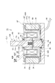
図2に示すように、ブレーキ付きモータ1は、回転シャフト10と、ケース20と、ステータコア23と、複数の駆動用コイル24と、ブレーキ30と、エンコーダ70と、ケーブル80とを備える。以下、各部の説明における「前後」は、回転シャフト10の一端側を前側とし、他端側を後側とした方向を意味する。
図2に示すように、ブレーキ付きモータ1は、回転シャフト10と、ケース20と、ステータコア23と、複数の駆動用コイル24と、ブレーキ30と、エンコーダ70と、ケーブル80とを備える。以下、各部の説明における「前後」は、回転シャフト10の一端側を前側とし、他端側を後側とした方向を意味する。
回転シャフト10は、例えば鉄鋼又はステンレス等により構成されており、主軸11と、延出部12,13とを有する。主軸11の後側端部の外周には、全周に亘るフランジ部11aが形成されている。
延出部12は、主軸11と同心の軸部であり、主軸11の前側に連なっている。延出部13は、主軸11と同心の軸部であり、主軸11の後側に連なっている。
延出部12,13は主軸11に比べ細径である。
延出部12,13は主軸11に比べ細径である。
延出部13の外周には、2個の環状端子13aが設けられている。2個の環状端子13aは、回転シャフト10の中心軸線CL1に沿う方向に並ぶと共に、それぞれ延出部13の全周に亘っている。
ケース20は、収容器21及び蓋22を有し、回転シャフト10を回転自在に保持する。収容器21はカップ状を呈し、蓋22は収容器21の開口を塞ぐ。収容器21及び蓋22は、例えばステンレス、アルミニウム合金又は樹脂材料等の非磁性材料により構成されている。
収容器21内の底面の中心部には、前方に開口する凹部21bが形成されている。凹部21bの底部の中心部には、開口21aが形成されている。収容器21には軸受26及び端子保持部27が設けられている。軸受26は、凹部21bに対して同心の環状を呈し、凹部21bの周縁部に取り付けられている。端子保持部27は、開口21aの周囲に位置し、収容器21の外面から後方に突出している。端子保持部27は、2本の端子27aを有する。2本の端子27aは前後方向に並び、それぞれ開口21aの中心側に突出している。
蓋22の中心部には、開口22aが形成されている。蓋22には軸受25が設けられている。軸受25は、開口22aに対して同心の環状を呈し、開口22aの周縁部に取り付けられている。
軸受25は主軸11の前側端部を回転自在に支持し、軸受26は主軸11の後側端部を回転自在に支持する。フランジ部11aは、回転シャフト10の位置決め部として機能する。すなわち、フランジ部11aが前側から軸受26に当接することで、中心軸線CL1に沿う方向での回転シャフト10の位置が定まる。この状態で、延出部12は開口22aから前方に延出し、延出部13の後側端部は開口21aから後方に延出する。延出部13の2個の環状端子13aは収容器21の外に位置し、2本の端子27aが2個の環状端子13aにそれぞれ接触する。
ステータコア23及び駆動用コイル24は、ブレーキ付きモータ1のステータSTを構成する。ステータコア23は、例えば3%珪素鉄等の鉄系の軟磁性材料により構成され、収容器21内に収容されている。ステータコア23は、筒状を呈すると共に内側に12個のティース23aを有する。ステータコア23は、収容器21の内周面に嵌合した状態で、接着、ボルト締結又は溶接等により収容器21に固定されている。なお、ステータコア23は、例えば珪素鋼板に絶縁被膜を形成した電磁鋼板を積層したものであってもよく、軟磁性複合材料(SMC)を圧縮成形したものであってもよく、鉄系の軟磁性材料のみにより形成されたものであってもよい。
12個のティース23aは、周方向に並んで回転シャフト10の中心軸線CL1を囲んでおり、それぞれ前後方向に沿うと共に中心軸線CL1側に突出している。
12個の駆動用コイル24は、中心軸線CL1を囲むようにケース20内に設けられており(図3参照)、12個のティース23aにそれぞれ巻き付けられている。すなわち、駆動用コイル24はケース20に固定されている。12個の駆動用コイル24は、例えば3相交流の供給を受け、回転シャフト10を回転させるための回転磁界を発生させる。なお、ティース23a及び駆動用コイル24の数は12個に限られず、適宜変更可能である。
ブレーキ30は、コア本体40と、弾性部材31と、ブレーキ用コイル32と、ブレーキパッド33とを有し、ケース20内に設けられている。ブレーキ30は、回転シャフト10と共にブレーキ付きモータ1のロータRTを構成する。
コア本体40は、例えば3%珪素鉄等の鉄系の軟磁性材料により構成され、中心軸線CL1を囲む環状を呈する。コア本体40は、ケース20内において、ブレーキ用コイル32と回転シャフト10との間に収容されている。コア本体40内には、その全周に亘って環状空間S1が形成されている。すなわち、ブレーキ30は環状空間S1を更に有する。なお、コア本体40は、例えば珪素鋼板に絶縁被膜を形成した電磁鋼板を積層したものであってもよく、軟磁性複合材料(SMC)を圧縮成形したものであってもよく、鉄系の軟磁性材料のみにより形成されたものであってもよい。
コア本体40は、中心軸線CL1に沿って伸縮自在となっている。具体的に、コア本体40は、第1コア部材50及び第2コア部材60により構成されている。
第1コア部材50は、ケース20内の前側(回転シャフト10の一端側)に設けられており、筒状部51と、円板部52と、3個の第1突極53とを有する(図3及び図4参照)。筒状部51は主軸11に嵌合する。円板部52は、筒状部51の前側端部の全周から外周側に張り出している。円板部52の周縁部は、中心軸線CL1を囲む第1環状部R1を構成する。3個の第1突極53は、第1環状部R1の周方向に並び、それぞれ第1環状部R1から後側(後述の第2環状部R2側)に突出している。
第2コア部材60は、ケース20内の後側(回転シャフト10の他端側)に設けられており、筒状部61と、円板部62と、3個の第2突極63とを有する(図3及び図4参照)。筒状部61は、主軸11に嵌合する。円板部62は、筒状部61の後側端部の全周から外周側に張り出している。円板部62の周縁部は、中心軸線CL1を囲む第2環状部R2を構成する。第2環状部R2は、第1環状部R1に比べ後側に位置する。第1環状部R1と第2環状部R2とは中心軸線CL1に沿う方向に並ぶ。3個の第2突極63は、第2環状部R2の周方向に並び、それぞれ第2環状部R2から前側(第1環状部R1側)に突出している。3個の第2突極63は、3個の第1突極53の間にそれぞれ入り込んでいる。これにより、3個の第2突極63は、第2環状部R2の周方向で第1突極53と交互に並んでいる。第1環状部R1と第2突極63との間、第1突極53と第2突極63との間、及び第1突極53と第2環状部R2との間には、間隙67が形成されている。
筒状部51及び筒状部61は環状空間S1の内周側を画し、円板部52は環状空間S1の前側を画し、円板部62は環状空間S1の後側を画し、第1突極53及び第2突極63は環状空間S1の外周側を画す。すなわち、第2コア部材60は、第1コア部材50と協働して環状空間S1を構成する。
筒状部51及び筒状部61と主軸11との間には、回転防止用のキー14が配置されている(図3参照)。これにより、回転シャフト10に対する第1コア部材50及び第2コア部材60の相対回転が規制されている。このため、第1コア部材50及び第2コア部材60は、回転シャフト10と共に回転する回転部P1に相当する。
筒状部51は、接着、ボルト締結又は溶接等の手段により主軸11に固定されている。すなわち、第1コア部材50は、中心軸線CL1に沿う移動を規制された状態で回転シャフト10に取り付けられている。
一方、筒状部61は、主軸11に固定されておらず、中心軸線CL1に沿って移動可能となっている。すなわち、第2コア部材60は、中心軸線CL1に沿って移動可能な状態で回転シャフト10に取り付けられている。第1コア部材50から第2コア部材60が離間すると、コア本体40の全長が伸びる。第1コア部材50に第2コア部材60が近接すると、コア本体40の全長が縮まる。すなわち、コア本体40は、第1コア部材50に対する第2コア部材60の離間又は近接に応じて伸縮する。
弾性部材31は、例えば金属製のコイルばね又は板ばね等である。弾性部材31は、中心軸線CL1に沿って圧縮された状態で、筒状部51と筒状部61との間に配置されている。圧縮に応じた弾性部材31の反発力は、第2コア部材60を第1コア部材50から離間させるように作用する。すなわち弾性部材31は、第2コア部材60を第1コア部材50から離間させ、コア本体40を伸長するための要素として機能する。
ブレーキ用コイル32は、中心軸線CL1を囲むように巻かれて環状空間S1に収容されており、例えば接着等により第1コア部材50に固定されている。ブレーキ用コイル32の巻線の両端部は、2個の環状端子13aにそれぞれ接続されている。ブレーキ用コイル32は、通電に応じて磁界を発生させる。この磁界はブレーキ用コイル32の巻線を囲むように形成され、コア本体40の第1コア部材50及び第2コア部材60を通る。ブレーキ用コイル32による磁界が発生すると、コア本体40には、当該磁界の経路を短縮するように力が作用する。この力により、弾性部材31の反発力に抗して第2コア部材60が第1コア部材50に近接させられる。すなわちブレーキ用コイル32は、コア本体40を短縮するための磁界を発生させる。
ブレーキパッド33は、例えば金属繊維等を骨格材料として10~20種の金属材料、樹脂材料又はゴム材料等を組み合わせた複合材により構成されている。ブレーキパッド33は、例えば円板部62に平行なシート状を呈し、接着等により円板部62の後面に固定されている。このため、ブレーキパッド33は回転シャフト10と共に回転する。弾性部材31によりコア本体40が伸長されると、ブレーキパッド33は収容器21の底部に接触する。回転シャフト10と共に回転するブレーキパッド33と、収容器21の底部とが接触することで、回転シャフト10とケース20との間に摩擦抵抗が生じる。すなわち、ブレーキパッド33は、コア本体40の伸長に応じて回転シャフト10とケース20との間に摩擦抵抗を発生させるように構成された接触部を構成する。なお、以上の説明から明らかであるように、回転シャフト10とケース20との間に摩擦抵抗が発生することは、回転シャフト10とケース20とが直に擦れ合うことのみを意味するものではない。例えば、回転シャフト10とケース20との間に1又は複数の部材が介在している場合に、部材同士の摩擦に伴い回転シャフト10とケース20との間に回転抵抗が発生することも、回転シャフト10とケース20との間に摩擦抵抗が発生することに含まれる。
エンコーダ70は、スリット板71と検出部72とを有し、凹部21b内に収容されている。スリット板71は、周方向に並ぶ複数のスリットを有する円板状の部材であり、その中央には延出部13が通されている。スリット板71は、延出部13の周面に固定されており、延出部13と共に回転する。検出部72は、例えばフォトダイオード等により構成され、スリット板71のスリットの通過に応じた電気信号を出力する。
ケーブル80は、複数の電線を束ねたものである。一部の電線は、駆動用コイル24に接続されており、駆動用コイル24に電力を伝える。他の一部の電線は、端子27aに接続されており、環状端子13aを介してブレーキ用コイル32に電力を伝える。他の一部の電線は、検出部72の出力信号を外部のカウンター回路に伝送する。
(ブレーキ付きモータの動作)
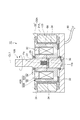
駆動用コイル24及びブレーキ用コイル32の両方に電力が供給されると、回転シャフト10が回転する。電力の供給に応じ、駆動用コイル24は、回転シャフト10を回転させるための回転磁界を発生させる。ブレーキ用コイル32は、コア本体40を短縮するための磁界を発生させる。電力の供給に応じ、ブレーキ用コイル32は、コア本体40を短縮するための磁界を発生させる。この磁界は、図5に示すように、第2コア部材60を第1コア部材50に近接させる。これに伴ってブレーキパッド33が収容器21から離間する。
駆動用コイル24及びブレーキ用コイル32の両方に電力が供給されると、回転シャフト10が回転する。電力の供給に応じ、駆動用コイル24は、回転シャフト10を回転させるための回転磁界を発生させる。ブレーキ用コイル32は、コア本体40を短縮するための磁界を発生させる。電力の供給に応じ、ブレーキ用コイル32は、コア本体40を短縮するための磁界を発生させる。この磁界は、図5に示すように、第2コア部材60を第1コア部材50に近接させる。これに伴ってブレーキパッド33が収容器21から離間する。
この状態において、第1突極53及び第2突極63は、ブレーキ用コイル32による磁界に応じて互いに逆の極性に磁化され、駆動用コイル24による回転磁界と相互に作用する磁界を形成する。駆動用コイル24による回転磁界と、第1突極53及び第2突極63が形成する磁界とは、相互に作用することで、コア本体40を回転磁界に追従させる磁力を発生させる。この磁力により、回転シャフト10が回転する。
このように、第1突極53及び第2突極63が形成する磁界も、回転シャフト10を回転させるための磁界として用いられる。この磁界は、ブレーキ用コイル32により発生させられてコア本体40を通ったものである。従って、ブレーキ用コイル32により発生させられた磁界は、コア本体40の短縮と、回転シャフト10の回転とに共用される。また、コア本体40を短縮するための磁界と、回転シャフト10を回転させるための磁界とは、コア本体40内では同一の経路を通る。すなわち、コア本体40の少なくとも一部は、コア本体40を短縮するための磁界の経路と、回転シャフト10を回転させるための磁界の経路とに共用される。
コア本体40を短縮するための磁界及び回転シャフト10を回転させるための磁界の経路は、回転部P1を構成する第1コア部材50及び第2コア部材60の両方を通る。このため、コア本体40における回転部P1の少なくとも一部が、コア本体40Aを短縮するための磁界の経路と、回転シャフト10Aを回転させるための磁界の経路とに共用される。
駆動用コイル24への電力とブレーキ用コイル32への電力とが遮断されると、回転シャフト10が制動される。これらの電力の遮断に伴い、駆動用コイル24による回転磁界が消えると共に、ブレーキ用コイル32による磁界も消える。ブレーキ用コイル32による磁界が消えると、弾性部材31が第1コア部材50から第2コア部材60を離間させる。これに伴い、ブレーキパッド33が収容器21に接触し、回転シャフト10とケース20との間に摩擦抵抗が発生する。この摩擦抵抗により、回転中の回転シャフト10が制動される。すなわち、ブレーキ30が回転シャフト10に対する制動力を発生させ、この制動力により回転シャフト10が速やかに停止する。
以上に説明したように、ブレーキ付きモータ1によれば、コア本体40の少なくとも一部分は、コア本体40を短縮するための磁界の経路と、回転シャフト10を回転させるための磁界の経路とに共用される。すなわち、コア本体40の少なくとも一部分は、ブレーキ30の駆動と回転シャフト10の駆動とに共用される。これにより、ブレーキ付きモータ1を小型化できる。
ブレーキ用コイル32により発生させられた磁界は、コア本体40の短縮と、回転シャフト10の回転とに共用される。すなわち、ブレーキ用コイル32もブレーキ30の駆動と回転シャフト10の駆動とに共用される。これにより、ブレーキ付きモータ1を更に小型化できる。
駆動用コイル24はケース20に固定され、コア本体40は、回転シャフト10と共に回転する回転部P1を有する。回転部P1の少なくとも一部は、コア本体40を短縮するための磁界の経路と、回転シャフト10を回転させるための磁界の経路とに共用される。駆動用コイル24は回転しないので、駆動用コイル24に電力を供給する構成を単純化できる。従って、ブレーキ付きモータ1を更に小型化できる。
なお、ケース20内において、第1コア部材50と第2コア部材60との配置が逆転していてもよい。すなわち、第1コア部材50が後側に配置され、第2コア部材60が前側に配置されていてもよい。この場合、ブレーキパッド33は、回転シャフト10の制動時に蓋22に接触する。
〔第2実施形態〕
第2実施形態のブレーキ付きモータ1Aと、第1実施形態のブレーキ付きモータ1との主な相違点は、ブレーキ付きモータ1Aのブレーキ用コイル32が回転しないように構成されている点である。
第2実施形態のブレーキ付きモータ1Aと、第1実施形態のブレーキ付きモータ1との主な相違点は、ブレーキ付きモータ1Aのブレーキ用コイル32が回転しないように構成されている点である。
図6に示すように、ブレーキ付きモータ1Aは、ブレーキ付きモータ1の回転シャフト10、ケース20及びブレーキ30が、回転シャフト10A、ケース20A及びブレーキ30Aに置き換わったものである。
回転シャフト10Aの延出部13には環状端子13aが設けられていない。これに伴い、回転シャフト10Aの延出部13は回転シャフト10の延出部13に比べ短縮されており、凹部21b内に収まっている。これらの点を除き、回転シャフト10Aは回転シャフト10と同様に構成されている。
ケース20Aは、収容器21の代わりに収容器21Aを有する。収容器21Aには、収容器21の開口21a及び端子保持部27をなくしたものである。これらの点を除き、ケース20Aはケース20と同様に構成されている。
延出部13に環状端子13aが設けられておらず、収容器21Aに端子保持部27が設けられていないのは、電力の供給中にブレーキ用コイル32を回転させる必要がないためである。
ブレーキ30Aは、コア本体40Aと、弾性部材31と、ブレーキ用コイル32と、ブレーキパッド33とを有する。コア本体40Aは、コア本体40と同様の軟磁性材料により構成されており、第1コア部材50Aと第2コア部材60Aとを有する。
第1コア部材50Aは、筒状部54と円板部55とを有する。筒状部54は主軸11に嵌合する。円板部55は、筒状部51の前側端部を囲む環状を呈する。
第2コア部材60Aは、第2コア部材60と同様の筒状部61、円板部62及び3個の第2突極63を有するのに加え、環体65及び3個の第1突極66を更に有する。環体65は、平面視で円板部62の周縁部(第2環状部R2)と重なるように設けられており、第2突極63よりも前側において円板部55の周囲に位置している。環体65は第1環状部R1に相当する。すなわち、第2環状部R2は、第1環状部R1に比べ後側に位置する。第1環状部R1と第2環状部R2とは中心軸線CL1に沿う方向に並ぶ。3個の第1突極66は、第1環状部R1の周方向に並び、それぞれ後方に突出している。3個の第1突極66は、3個の第2突極63の間にそれぞれ入り込んでいる。これにより、3個の第2突極63は、第2環状部R2の周方向で第1突極66と交互に並んでいる。
第1環状部R1と第2突極63との間、第1突極66と第2突極63との間、及び第1突極66と第2環状部R2との間には、間隙67が形成されている。この状態で、環体65及び第1突極66は、非磁性の接着剤等により円板部62及び第2突極63に固定されている。
ブレーキ付きモータ1の筒状部51及び筒状部61と同様に、回転シャフト10Aに対する筒状部54及び筒状部61の相対回転は規制されている。このため、筒状部54及び第2コア部材60Aは、回転シャフト10Aと共に回転する回転部P1に相当する。一方、円板部55は、接着、ボルト締結又は溶接等により蓋22に固定されている。このため、円板部55は、ケース20Aに固定された固定部P2に相当する。
筒状部54は、接着、ボルト締結又は溶接等により主軸11に固定されている。すなわち、第1コア部材50Aの回転部P1は、中心軸線CL1に沿う移動を規制された状態で回転シャフト10に取り付けられている。
一方、筒状部61は、主軸11に固定されておらず、中心軸線CL1に沿って移動可能となっている。すなわち、第2コア部材60Aは、中心軸線CL1に沿って移動可能な状態で回転シャフト10Aに取り付けられている。第1コア部材50Aから第2コア部材60Aが離間すると、コア本体40Aの全長が伸びる。第1コア部材50Aに第2コア部材60Aが近接すると、コア本体40Aの全長が縮まる。すなわち、コア本体40Aは、第1コア部材50Aに対する第2コア部材60Aの離間又は近接に応じて伸縮する。
弾性部材31は、筒状部54と筒状部61との間に配置されている。弾性部材31の反発力は、第2コア部材60Aを第1コア部材50Aから離間させるように作用する。すなわち弾性部材31は、第2コア部材60Aを第1コア部材50Aから離間させ、コア本体40Aを伸長するための要素として機能する。
ブレーキ用コイル32は、例えば接着等により円板部55に固定されている。ブレーキ用コイル32による磁界が発生すると、コア本体40Aには、当該磁界の経路を短縮するように力が作用する。この力により、弾性部材31の反発力に抗して第2コア部材60Aが第1コア部材50Aに近接させられる。すなわちブレーキ用コイル32は、コア本体40Aを短縮するための磁界を発生させる。
ブレーキパッド33は、例えば接着等により円板部62の後面に固定されているので、回転シャフト10と共に回転する。弾性部材31によりコア本体40Aが伸長されると、ブレーキパッド33は収容器21の底部に接触する。すなわち、ブレーキパッド33は、コア本体40Aの伸長に応じて回転シャフト10Aとケース20Aとの間に摩擦抵抗を発生させる接触部を構成する。
なお、ブレーキ付きモータ1Aにおいては、筒状部54、第2コア部材60A、弾性部材31及びブレーキパッド33が回転シャフト10Aと共にロータRTを構成する。
ブレーキ付きモータ1Aは、ブレーキ付きモータ1と同様に動作する。すなわち、駆動用コイル24及びブレーキ用コイル32の両方に電力が供給されると、ブレーキパッド33が収容器21の底部から離間し、回転シャフト10Aが回転する(図7参照)。駆動用コイル24への電力とブレーキ用コイル32への電力とが遮断されると、回転シャフト10Aが制動される。
第1突極66及び第2突極63は、ブレーキ用コイル32による磁界に応じて互いに逆の極性に磁化され、駆動用コイル24による回転磁界と相互に作用する磁界を形成する。従って、ブレーキ付きモータ1の回転シャフト10が回転するときと同様に、ブレーキ用コイル32により発生させられた磁界は、コア本体40Aの短縮と、回転シャフト10Aの回転とに共用される。コア本体40Aの少なくとも一部は、コア本体40Aを短縮するための磁界の経路と、回転シャフト10Aを回転させるための磁界の経路とに共用される。また、コア本体40Aにおける回転部P1の少なくとも一部が、コア本体40Aを短縮するための磁界の経路と、回転シャフト10Aを回転させるための磁界の経路とに共用される。
ブレーキ付きモータ1Aによっても、ブレーキ付きモータ1と同様の効果が得られる。更に、ブレーキ付きモータ1Aによれば、駆動用コイル24が回転しないのに加え、ブレーキ用コイル32も回転しないので、ブレーキ用コイル32に電力を供給する構成も単純化できる。従って、ブレーキ付きモータ1Aを更に小型化できる。
なお、ケース20A内において、第1コア部材50Aと第2コア部材60Aとの配置が逆転していてもよい。すなわち、第1コア部材50Aが後側に配置され、第2コア部材60Aが前側に配置されていてもよい。この場合、円板部55は収容器21の底部に固定される。ブレーキパッド33は、回転シャフト10の制動時に蓋22に接触する。
〔第3実施形態〕
第3実施形態のブレーキ付きモータ1Bと、第2実施形態のブレーキ付きモータ1Aとの主な相違点は、ブレーキ付きモータ1Bが第1突極66及び第2突極63を有さず、代わりに複数の永久磁石34を有する点である。
第3実施形態のブレーキ付きモータ1Bと、第2実施形態のブレーキ付きモータ1Aとの主な相違点は、ブレーキ付きモータ1Bが第1突極66及び第2突極63を有さず、代わりに複数の永久磁石34を有する点である。
図8に示すように、ブレーキ付きモータ1Bは、ブレーキ付きモータ1Aのブレーキ30Aがブレーキ30Bに置き換わったものである。
ブレーキ30Bは、ブレーキ30Aのコア本体40Aがコア本体40Bに置き換わった構成と、8個の永久磁石34とを有する。コア本体40Bは、コア本体40Aの第2コア部材60Aが第2コア部材60Bに置き換わったものであり、コア本体40Aと同様の軟磁性材料により構成されている。
第2コア部材60Bは、筒状部61と、円板部62と、周壁部68とを有する。周壁部68は、円板部62の周縁部から前側に突出した筒状を呈する。周壁部68の前側端部は、円板部55の周囲に位置している。
第2コア部材60Aと同様に、第2コア部材60Bは、中心軸線CL1に沿って移動可能な状態で回転シャフト10Aに取り付けられており、回転シャフト10Aと共に回転する。このため、第2コア部材60Bは、回転シャフト10Aと共に回転する回転部P1に相当する。
8個の永久磁石34は、中心軸線CL1を囲むように並んでおり、それぞれ接着等により周壁部68の外周面に固定されている(図9参照)。それぞれの永久磁石34は、中心軸線CL1に沿って延びると共に、周壁部68の外周面に沿って湾曲した板状を呈する。
8個の永久磁石34のうち、4個の永久磁石34AのN極は外周側に向けられている。残り4個の永久磁石34BのN極は内周側に向けられている。永久磁石34A及び永久磁石34Bは、周壁部68の周方向で交互に並んでいる。なお、永久磁石34の個数は8個に限られず、適宜変更可能である。
なお、ブレーキ付きモータ1Bにおいては、筒状部54、第2コア部材60B、弾性部材31、ブレーキパッド33及び永久磁石34が回転シャフト10Aと共にロータRTを構成する。
ブレーキ付きモータ1Bは、ブレーキ付きモータ1Aと同様に動作する。すなわち、駆動用コイル24及びブレーキ用コイル32の両方に電力が供給されると、回転シャフト10Aが回転する。駆動用コイル24への電力とブレーキ用コイル32への電力とが遮断されると、回転シャフト10Aが制動される。
電力の供給に応じ、ブレーキ用コイル32は、コア本体40Bを短縮するための磁界を発生させる。この磁界は、筒状部54、円板部55、周壁部68、円板部62及び筒状部61を通り、第2コア部材60Bを第1コア部材50Aに近接させる。これに伴って、ブレーキパッド33が収容器21から離間する(図10参照)。
電力の供給に応じ、駆動用コイル24は回転磁界を発生させる。隣り合う永久磁石34A,34Bは、駆動用コイル24による回転磁界と相互に作用する磁界を形成する。駆動用コイル24による回転磁界と、永久磁石34A,34Bによる磁界とは、相互に作用することで、コア本体40Bを回転させる磁力を発生させる。この磁力により、回転シャフト10Aが回転する。
このように、永久磁石34A,34Bによる磁界も、回転シャフト10Aを回転させるための磁界として用いられる。この磁界は、周方向に沿って周壁部68内を通る。一方、ブレーキ用コイル32による磁界は、軸線方向に沿って周壁部68内を通る。このため、周壁部68の少なくとも一部は、コア本体40Bを短縮するための磁界の経路と、回転シャフト10Aを回転させるための磁界の経路とに共用される。すなわち、コア本体40Bの少なくとも一部は、コア本体40Bを短縮するための磁界の経路と、回転シャフト10Aを回転させるための磁界の経路とに共用される。また、コア本体40Bにおける回転部P1の少なくとも一部が、コア本体40Bを短縮するための磁界の経路と、回転シャフト10Aを回転させるための磁界の経路とに共用される。
ブレーキ付きモータ1Bによっても、コア本体40Bの少なくとも一部分は、ブレーキ30Bの駆動と回転シャフト10Aの駆動とに共用されるので、ブレーキ付きモータ1を小型化できる。
また、駆動用コイル24は回転しないので、駆動用コイル24に電力を供給する構成を単純化できる。ブレーキ用コイル32も回転しないので、ブレーキ用コイル32に電力を供給する構成も単純化できる。従って、ブレーキ付きモータ1を更に小型化できる。
なお、ケース20A内において、第1コア部材50Aと第2コア部材60Bとの配置が逆転していてもよい。すなわち、第1コア部材50Aが後側に配置され、第2コア部材60Bが前側に配置されていてもよい。この場合、円板部55は収容器21の底部に固定される。ブレーキパッド33は、回転シャフト10の制動時に蓋22に接触する。
ブレーキ30Bは、コア本体40Bの短縮時に、回転シャフト10Aに対する制動力を発生させるように構成されていてもよい。このような構成は、例えばブレーキパッド33を周壁部68の前側端部に設けることで実現される。周壁部68の前側端部に設けられたブレーキパッド33は、第2コア部材60Bが第1コア部材50Aに近接するのに応じて蓋22に接触し、回転シャフト10Aとケース20Aとの間に摩擦抵抗を発生させる。この場合、駆動用コイル24のみに電力が供給されると回転シャフト10Aが回転し、ブレーキ用コイル32に電力が供給されると回転シャフト10Aが制動される。
〔第4実施形態〕
第4実施形態のブレーキ付きモータ1Cと、第3実施形態のブレーキ付きモータ1Bとの主な相違点は、ブレーキ付きモータ1Cにおいて、コア本体40Bの伸縮用の弾性部材31が回転シャフト10B内に配置されている点である。
第4実施形態のブレーキ付きモータ1Cと、第3実施形態のブレーキ付きモータ1Bとの主な相違点は、ブレーキ付きモータ1Cにおいて、コア本体40Bの伸縮用の弾性部材31が回転シャフト10B内に配置されている点である。
図11に示すように、ブレーキ付きモータ1Cは、ブレーキ付きモータ1Bの回転シャフト10A及びブレーキ30が回転シャフト10B及びブレーキ30Cに置き換わったものである。
回転シャフト10Bは、主軸11Aと、延出部12と、延出部13とを有する。主軸11Aは、回転シャフト10Aの主軸11に貫通孔11b及び収容空間11cが形成されたものである。貫通孔11bは、中心軸線CL1に直交する線に沿って、主軸11Aを貫通している。収容空間11cは、中心軸線CL1に沿って主軸11A内の中心部に形成されている。収容空間11cは貫通孔11bに比べ前側に位置し、貫通孔11bに開口している。これらの点を除き、回転シャフト10Bは回転シャフト10Aと同様に構成されている。
ブレーキ30Cは、ブレーキ30Bと同様の構成と、伝達部材36とを有する。伝達部材36は貫通孔11bに通されており、その両端部は第2コア部材60Bの内周面に接続されている。中心軸線CL1に沿う方向において、貫通孔11bは、伝達部材36よりも大きくなっている。このため、貫通孔11bの範囲内において、中心軸線CL1に沿った伝達部材36の移動が可能となっている(図12参照)。
ブレーキ30Cの弾性部材31は、中心軸線CL1に沿って圧縮された状態で、収容空間11c内に収容されており、その後側端部は伝達部材36に接している。弾性部材31の反発力は、伝達部材36と共に第2コア部材60Bを第1コア部材50Aから離間させるように作用する。すなわち弾性部材31は、第2コア部材60Bを第1コア部材50Aから離間させ、コア本体40Bを伸長するための要素として機能する。
なお、ブレーキ付きモータ1Cにおいては、筒状部54、第2コア部材60B、弾性部材31、ブレーキパッド33、永久磁石34及び伝達部材36が回転シャフト10Bと共にロータRTを構成する。
ブレーキ付きモータ1Cは、ブレーキ付きモータ1Bと同様に動作する。すなわち、駆動用コイル24及びブレーキ用コイル32の両方に電力が供給されると、回転シャフト10Aが回転する。駆動用コイル24への電力とブレーキ用コイル32への電力とが遮断されると、回転シャフト10Aが制動される。
電力の供給に応じ、ブレーキ用コイル32は、コア本体40Bを短縮するための磁界を発生させる。この磁界は、第2コア部材60Bを第1コア部材50Aに近接させる(図12参照)。これに伴って、ブレーキパッド33が収容器21Aから離間する。第2コア部材60Bと共に、伝達部材36も貫通孔11b内で前側に移動し、弾性部材31を圧縮する。ブレーキ用コイル32への電力が遮断されると、弾性部材31の反発力により伝達部材36が後側に押される。これに伴い第2コア部材60Bが第1コア部材50Aから離間し、ブレーキパッド33が収容器21の底部に接触する。
ブレーキ付きモータ1Cによっても、ブレーキ付きモータ1Bと同様の効果が得られる。ブレーキ付きモータ1Cにより例示したように、コア本体40Bを伸長するための弾性部材31は、必ずしも第1コア部材50Aと第2コア部材60Bとの間に配置されている必要はない。第1コア部材50Aから離間する方向に向かう反発力を第2コア部材60Bに作用させられる配置であれば、弾性部材31はどのように配置されていてもよい。
〔第5実施形態〕
第5実施形態のブレーキ付きモータ1Dと、第3実施形態のブレーキ付きモータ1Bとの相違点は、ブレーキ付きモータ1Dにおいて、ステータコア23A及び駆動用コイル24をコア本体40Cの内側に配置した点である。
第5実施形態のブレーキ付きモータ1Dと、第3実施形態のブレーキ付きモータ1Bとの相違点は、ブレーキ付きモータ1Dにおいて、ステータコア23A及び駆動用コイル24をコア本体40Cの内側に配置した点である。
図13に示すように、ブレーキ付きモータ1Dは、ブレーキ付きモータ1Bの回転シャフト10A、ステータコア23及びブレーキ30Bが、回転シャフト10C、ステータコア23A及びブレーキ30Dに置き換わったものである。
回転シャフト10Cは、回転シャフト10Aの主軸11が主軸11Bに置き換わったものである。主軸11Bは、主軸11と同様に軸受25及び軸受26により回転自在に支持されている。延出部12は主軸11Bの一端側に連なり、延出部13は主軸11Bの他端側に連なっている。
主軸11Bの両端部には、主軸11Bの他の部分に比べて細径の細径部11d,11eがそれぞれ形成されている。細径部11dは軸受25に嵌合し、細径部11eは軸受26に嵌合している。細径部11d,11eと、主軸11Bの他の部分との段差が、軸受25,26に接触することにより、軸受25,26に対する主軸11Bの位置が定まっている。主軸11Bの前側の外周には、フランジ部11fが設けられている。
ステータコア23Aは、ステータコア23と同様の軟磁性材料により構成され、筒状を呈すると共に外側に12個のティース23bを有する。ステータコア23Aは、主軸11Bを囲んだ状態で、収容器21Aの底部に固定されている。ステータコア23Aの内径は主軸11Bの外径に近い大きさであり、ステータコア23Aの内周面は主軸11Bの外周面に近接している。
12個のティース23bは、周方向に並んで回転シャフト10の中心軸線CL1を囲んでいる。ティース23bのそれぞれは、前後方向に沿うと共に、外周側に突出している。これらのティース23bには、12個の駆動用コイル24がそれぞれ巻き付けられている。すなわち、12個の駆動用コイル24は、中心軸線CL1を囲むように設けられ、ケース20Aに固定されている。なお、ティース23b及び駆動用コイル24の数は12個に限られず、適宜変更可能である。
ブレーキ30Dは、ブレーキ30Bのコア本体40Bがコア本体40Cに置き換わった構成と、回転板37とを備える。回転板37は中心部が開口した円板状を呈する。回転板37の中心部には主軸11Bの前側部分が嵌合している。
回転板37は、ブレーキ付きモータ1Bにおける第2コア部材60Bと同様に、中心軸線CL1に沿って移動可能な状態で回転シャフト10Cに取り付けられており、回転シャフト10Cと共に回転する。
回転板37はフランジ部11fに比べ前側に位置しており、回転板37の内側部分とフランジ部11fとの間には弾性部材31が配置されている。弾性部材31は、中心軸線CL1に沿う方向で圧縮されており、その反発力により回転板37を蓋22側に押す。
回転板37の前面において、外周近傍の部分には、ブレーキパッド33が設けられている。ブレーキパッド33は、例えば接着等により回転板37の前面に固定されているので、回転板37と共に回転する。
コア本体40Cは、コア本体40Bと同様の軟磁性材料により構成され、中心軸線CL1を囲む環状を呈する。コア本体40Cは、ケース20A内において、ステータコア23Aの外側に収容されている。コア本体40Cには、その全周に亘って環状空間S1が形成されている。すなわち、ブレーキ30Dは環状空間S1を更に有する。
コア本体40Cは、中心軸線CL1に沿って伸縮自在となっている。具体的に、コア本体40Cは、第1コア部材50Cと第2コア部材60Cとにより構成されている。
第1コア部材50Cは、中心軸線CL1側に開口した断面C字状を呈し、環状空間S1の前側、後側及び外周側を画している。第1コア部材50Cは収容器21Aの底部に、例えば接着、ボルト締結又は溶接等により固定されている。このため、第1コア部材50Cは、ケース20Aに固定される固定部P2に相当する。
第2コア部材60Cは中心軸線CL1を囲む筒状を呈し、第1コア部材50Cの内周側を塞ぐように配置されている。すなわち第2コア部材60Cは、環状空間S1の内周側を画しており、第1コア部材50Cと協働して環状空間S1を構成している。
第2コア部材60Cの前側端部は、例えば接着、ボルト締結又は溶接等により回転板37に固定されている。これにより、第2コア部材60Cは、中心軸線CL1に沿って移動可能な状態で回転シャフト10Cに取り付けられており、回転シャフト10Cと共に回転する。このため、第2コア部材60Cは、回転シャフト10Cと共に回転する回転部P1に相当する。
第1コア部材50Cから第2コア部材60Cが離間すると、コア本体40Cの全長が伸びる。第1コア部材50Cに第2コア部材60Cが近接すると、コア本体40Cの全長が縮まる。すなわち、コア本体40Cは、第1コア部材50Cに対する第2コア部材60Cの離間又は近接に応じて伸縮する。
環状空間S1内にはブレーキ用コイル32が収容される。ブレーキ用コイル32は、例えば接着等により第1コア部材50Cに固定されている。
第2コア部材60Cの内周面には、8個の永久磁石34が例えば接着等により固定されている。8個の永久磁石34は、中心軸線CL1を囲むように並んでいる。
なお、ブレーキ付きモータ1Dにおいては、回転板37、第2コア部材60C、永久磁石34、弾性部材31及びブレーキパッド33が回転シャフト10Cと共にロータRTを構成する。ステータコア23A及び駆動用コイル24がステータSTを構成する。
ブレーキ付きモータ1Dは、ブレーキ付きモータ1Bと同様に動作する。すなわち、駆動用コイル24及びブレーキ用コイル32の両方に電力が供給されると、回転シャフト10Cが回転する。駆動用コイル24への電力とブレーキ用コイル32への電力とが遮断されると、回転シャフト10Cが制動される。
電力の供給に応じ、ブレーキ用コイル32は、コア本体40Cを短縮するための磁界を発生させる。この磁界は、第2コア部材60Cを第1コア部材50Cに近接させる。第2コア部材60Cの移動に伴って回転板37も後側に移動し、ブレーキパッド33が蓋22から離間する。弾性部材31は、回転板37により圧縮される。
ブレーキ用コイル32への電力を遮断すると、弾性部材31の反発力により回転板37が前側に押され、ブレーキパッド33が蓋22に接触する。回転板37の移動に伴って、第2コア部材60Cが第1コア部材50Cから離間し、コア本体40Cが伸長される。
ブレーキ付きモータ1Dにおいても、第2コア部材60Cの少なくとも一部分が、コア本体40Cを短縮するための磁界の経路と、回転シャフト10Cを回転させるための磁界の経路とに共用される。すなわち、コア本体40Cの少なくとも一部は、コア本体40Cを短縮するための磁界の経路と、回転シャフト10Cを回転させるための磁界の経路とに共用される。また、コア本体40Cにおける回転部P1の少なくとも一部が、コア本体40Cを短縮するための磁界の経路と、回転シャフト10Cを回転させるための磁界の経路とに共用される。このため、ブレーキ付きモータ1Dによっても、ブレーキ付きモータ1Bと同様の効果が得られる。
ブレーキ付きモータ1Dにより例示されるように、駆動用コイル24をコア本体40Cの内周側に配置したとしても、コア本体40Cを短縮するための磁界の経路と、回転シャフト10Cを回転させるための磁界の経路とに、コア本体40Cの少なくとも一部を共用することは可能である。すなわち、コア本体を短縮するための磁界の経路と、ロータを回転させるための磁界の経路とにコア本体の一部を共用する構成は、駆動用コイルをコア本体の外周側に配置したものに限られない。
以上、実施形態について説明してきたが、本発明は必ずしも上述した実施形態に限定されるものではなく、その要旨を逸脱しない範囲で様々な変更が可能である。
例えば、各実施形態におけるブレーキパッド33は、必ずしも必須ではなく、ブレーキパッド33が取り付けられている面自体を接触部として活用してもよい。収容器21又は蓋22側にブレーキパッド33が取り付けられていてもよい。
駆動用コイル24を回転シャフト10,10Aに固定し、第1突極53,66及び第2突極63をケース20,20Aに固定してもよい。駆動用コイル24を回転シャフト10B,10Cに固定し、永久磁石34をケース20Aに固定してもよい。
各実施形態の構成要素を適宜組み合わせて用いてもよい。例えば、ブレーキ付きモータ1又はブレーキ付きモータ1Aにおいて、第1突極53,66と第2突極63との間等に永久磁石を配置してもよい。
本発明は、ブレーキ付きモータに利用できる。
1,1A,1B,1C,1D…ブレーキ付きモータ、10,10A,10B,10C…回転シャフト、20,20A…ケース、24…駆動用コイル、30,30A,30B,30C,30D…ブレーキ、31…弾性部材、32…ブレーキ用コイル、33…ブレーキパッド(接触部)、34…永久磁石、40,40A,40B,40C…コア本体、50,50A,50C…第1コア部材、53,66…第1突極、60,60A,60B,60C…第2コア部材、63…第2突極、CL1…中心軸線、P1…回転部、P2…固定部、R1…第1環状部、R2…第2環状部、S1…環状空間。
Claims (10)
- 回転シャフトと、
前記回転シャフトを回転自在に保持するケースと、
前記回転シャフトの中心軸線を囲むように前記ケース内に設けられ、前記回転シャフトを回転させるための磁界を発生させる複数の駆動用コイルと、
前記ケース内に設けられ、前記回転シャフトに対する制動力を発生させるブレーキと、を備え、
前記ブレーキは、
軟磁性材料により構成され、前記回転シャフトの中心軸線を囲む環状を呈すると共に、当該中心軸線に沿う方向で伸縮自在となるように設けられたコア本体と、
全周に亘って前記コア本体内に形成された環状空間と、
前記コア本体を伸長するための弾性部材と、
前記回転シャフトの中心軸線を囲むように巻かれて前記環状空間内に収容され、前記コア本体を短縮するための磁界を発生させるブレーキ用コイルと、
前記コア本体の伸長又は短縮に応じて前記回転シャフトと前記ケースとの間に摩擦抵抗を発生させる接触部と、を有し、
前記コア本体の少なくとも一部分は、前記コア本体を短縮するための磁界の経路と、前記回転シャフトを回転させるための磁界の経路とに共用される、ブレーキ付きモータ。 - 前記コア本体は、
前記回転シャフトの中心軸線に沿う方向に並ぶ第1環状部及び第2環状部と、
前記第1環状部の周方向に並び、それぞれ前記第1環状部から前記第2環状部側に突出した複数の第1突極と、
前記第2環状部の周方向に並び、それぞれ前記第2環状部から前記第1環状部側に突出し、当該周方向で前記第1突極と交互に並ぶ複数の第2突極と、を有し、
前記第1突極及び前記第2突極は、前記ブレーキ用コイルによる磁界に応じて互いに逆の極性に磁化され、前記駆動用コイルによる磁界と相互に作用する磁界を形成し、
前記接触部は、前記コア本体の伸長に応じて前記回転シャフトと前記ケースとの間に摩擦抵抗を発生させる、請求項1記載のブレーキ付きモータ。 - 前記ブレーキは、
前記回転シャフトの中心軸線を囲むように並んで前記コア本体に固定された複数の永久磁石を更に有し、
前記複数の永久磁石は、前記駆動用コイルによる磁界と相互に作用する磁界を発生させる、請求項1又は2記載のブレーキ付きモータ。 - 前記駆動用コイルは前記ケースに固定され、
前記コア本体は、前記回転シャフトと共に回転する回転部を有し、
前記回転部の少なくとも一部は、前記コア本体を短縮するための磁界の経路と、前記回転シャフトを回転させるための磁界の経路とに共用される、請求項1~3のいずれか一項記載のブレーキ付きモータ。 - 前記コア本体は、前記ケースに固定された固定部を更に有し、
前記ブレーキ用コイルは前記固定部に固定される、請求項4記載のブレーキ付きモータ。 - 前記複数の駆動用コイルは前記ケースに固定され、
前記コア本体は、
第1コア部材と、
前記回転シャフトの中心軸線に沿って移動可能な状態で前記回転シャフトに取り付けられ、前記第1コア部材と協働して前記環状空間を構成する第2コア部材と、を有し、前記第1コア部材に対する前記第2コア部材の離間及び近接に応じて伸縮し、
前記弾性部材は、前記第2コア部材を前記第1コア部材から離間させ、
前記ブレーキ用コイルは、前記第2コア部材を前記第1コア部材に近接させるための磁界を発生させ、
前記接触部は、前記コア本体の伸長又は短縮に応じて前記第2コア部材と前記ケースとの間に摩擦抵抗を発生させる、請求項1記載のブレーキ付きモータ。 - 前記第1コア部材は、
前記回転シャフトの中心軸線を囲む第1環状部と、
前記第1環状部の周方向に並ぶ複数の第1突極と、を有し、前記回転シャフトに取り付けられており、
前記第2コア部材は、
前記回転シャフトの中心軸線に沿う方向で前記第1環状部と並び、前記回転シャフトの中心軸線を囲む第2環状部と、
前記第2環状部の周方向に並ぶ複数の第2突極とを有し、
前記複数の第1突極は、それぞれ前記第1環状部から前記第2環状部側に突出し、
前記複数の第2突極は、それぞれ前記第2環状部から前記第1環状部側に突出し、前記第2環状部の周方向で前記第1突極と交互に並び、
前記第1突極及び前記第2突極は、前記ブレーキ用コイルによる磁界に応じて互いに逆の極性に磁化され、前記駆動用コイルによる磁界と相互に作用する磁界を形成し、
前記接触部は、前記コア本体の伸長に応じて前記回転シャフトと前記ケースとの間に摩擦抵抗を発生させる、請求項6記載のブレーキ付きモータ。 - 前記第2コア部材は、
前記回転シャフトの中心軸線に沿う方向に並び、それぞれ当該中心軸線を囲む第1環状部及び第2環状部と、
前記第1環状部の周方向に並び、それぞれ前記第1環状部から前記第2環状部側に突出した複数の第1突極と、
前記第2環状部の周方向に並び、それぞれ前記第2環状部から前記第1環状部側に突出し、当該周方向で前記第1突極と交互に並ぶ複数の第2突極と、を有し、
前記第1突極及び前記第2突極は、前記ブレーキ用コイルによる磁界に応じて互いに逆の極性に磁化され、前記駆動用コイルによる磁界と相互に作用する磁界を形成し、
前記接触部は、前記コア本体の伸長に応じて前記回転シャフトと前記ケースとの間に摩擦抵抗を発生させる、請求項6記載のブレーキ付きモータ。 - 前記ブレーキは、
前記回転シャフトの中心軸線を囲むように並んで前記第2コア部材に固定された複数の永久磁石を更に有し、
前記複数の永久磁石は、前記駆動用コイルによる磁界と相互に作用する磁界を発生させる、請求項6記載のブレーキ付きモータ。 - 前記第1コア部材は前記ケースに固定される固定部を有し、
前記ブレーキ用コイルは前記固定部に固定される、請求項8又は9記載のブレーキ付きモータ。
Priority Applications (2)
| Application Number | Priority Date | Filing Date | Title |
|---|---|---|---|
| PCT/JP2013/083957 WO2015092887A1 (ja) | 2013-12-18 | 2013-12-18 | ブレーキ付きモータ |
| JP2015553278A JP6194962B2 (ja) | 2013-12-18 | 2013-12-18 | ブレーキ付きモータ |
Applications Claiming Priority (1)
| Application Number | Priority Date | Filing Date | Title |
|---|---|---|---|
| PCT/JP2013/083957 WO2015092887A1 (ja) | 2013-12-18 | 2013-12-18 | ブレーキ付きモータ |
Publications (1)
| Publication Number | Publication Date |
|---|---|
| WO2015092887A1 true WO2015092887A1 (ja) | 2015-06-25 |
Family
ID=53402282
Family Applications (1)
| Application Number | Title | Priority Date | Filing Date |
|---|---|---|---|
| PCT/JP2013/083957 Ceased WO2015092887A1 (ja) | 2013-12-18 | 2013-12-18 | ブレーキ付きモータ |
Country Status (2)
| Country | Link |
|---|---|
| JP (1) | JP6194962B2 (ja) |
| WO (1) | WO2015092887A1 (ja) |
Cited By (1)
| Publication number | Priority date | Publication date | Assignee | Title |
|---|---|---|---|---|
| WO2022153438A1 (ja) * | 2021-01-14 | 2022-07-21 | 三菱電機株式会社 | 回転機 |
Families Citing this family (2)
| Publication number | Priority date | Publication date | Assignee | Title |
|---|---|---|---|---|
| KR101985144B1 (ko) * | 2018-08-13 | 2019-06-03 | 윤동진 | 전기자동차의 전기모터용 구동보조장치 |
| KR101928712B1 (ko) * | 2018-08-13 | 2019-02-27 | 윤동진 | 전기 전자석모터 |
Citations (4)
| Publication number | Priority date | Publication date | Assignee | Title |
|---|---|---|---|---|
| JP2004129389A (ja) * | 2002-10-02 | 2004-04-22 | Mitsubishi Motors Corp | インホイールモータ |
| JP2007051694A (ja) * | 2005-08-18 | 2007-03-01 | Yaskawa Electric Corp | 自己保持形ブレーキとその駆動方法 |
| JP2012197925A (ja) * | 2011-03-23 | 2012-10-18 | Mitsubishi Electric Corp | 回転電機のブレーキ装置 |
| JP2012237433A (ja) * | 2011-05-13 | 2012-12-06 | Yaskawa Electric Corp | モータ及びモータ用ブレーキ |
Family Cites Families (1)
| Publication number | Priority date | Publication date | Assignee | Title |
|---|---|---|---|---|
| JPH10341590A (ja) * | 1997-06-09 | 1998-12-22 | Kofu Meidensha:Kk | 保持ブレーキ機能を備えたブラシレスdcモータ装置 |
-
2013
- 2013-12-18 JP JP2015553278A patent/JP6194962B2/ja active Active
- 2013-12-18 WO PCT/JP2013/083957 patent/WO2015092887A1/ja not_active Ceased
Patent Citations (4)
| Publication number | Priority date | Publication date | Assignee | Title |
|---|---|---|---|---|
| JP2004129389A (ja) * | 2002-10-02 | 2004-04-22 | Mitsubishi Motors Corp | インホイールモータ |
| JP2007051694A (ja) * | 2005-08-18 | 2007-03-01 | Yaskawa Electric Corp | 自己保持形ブレーキとその駆動方法 |
| JP2012197925A (ja) * | 2011-03-23 | 2012-10-18 | Mitsubishi Electric Corp | 回転電機のブレーキ装置 |
| JP2012237433A (ja) * | 2011-05-13 | 2012-12-06 | Yaskawa Electric Corp | モータ及びモータ用ブレーキ |
Cited By (4)
| Publication number | Priority date | Publication date | Assignee | Title |
|---|---|---|---|---|
| WO2022153438A1 (ja) * | 2021-01-14 | 2022-07-21 | 三菱電機株式会社 | 回転機 |
| JPWO2022153438A1 (ja) * | 2021-01-14 | 2022-07-21 | ||
| JP7415050B2 (ja) | 2021-01-14 | 2024-01-16 | 三菱電機株式会社 | 回転機 |
| US12500478B2 (en) | 2021-01-14 | 2025-12-16 | Mitsubishi Electric Corporation | Rotator |
Also Published As
| Publication number | Publication date |
|---|---|
| JP6194962B2 (ja) | 2017-09-13 |
| JPWO2015092887A1 (ja) | 2017-03-16 |
Similar Documents
| Publication | Publication Date | Title |
|---|---|---|
| CN101779363B (zh) | 中空传动装置 | |
| CN107872116B (zh) | 带制动器的电动机 | |
| EP3439152B1 (en) | Rotary actuator and robot | |
| WO2001026203A1 (en) | Reduction gears-integrated actuator | |
| RU2694065C1 (ru) | Вращающаяся электрическая машина, оснащенная механизмом регулирования магнитного потока | |
| JP6710578B2 (ja) | 電動式直動アクチュエータ | |
| EP3483016A1 (en) | Electric linear actuator | |
| CN107872115B (zh) | 带制动器的电动机 | |
| JPWO2015181900A1 (ja) | 回転電機 | |
| CN105048666A (zh) | 转子及无刷电机 | |
| JPWO2017150487A1 (ja) | モータ | |
| JP6662740B2 (ja) | 三相dcブラシレスモータ | |
| JP6194962B2 (ja) | ブレーキ付きモータ | |
| JP2017093165A (ja) | 回転機、回転電動機、およびインホイールモータ | |
| JP6145391B2 (ja) | 駆動装置 | |
| JP2017229148A (ja) | 電動式直動アクチュエータ | |
| CN110959247B (zh) | 车轮驱动装置 | |
| JP6609138B2 (ja) | アキシャルギャップ型回転電機 | |
| JP6327130B2 (ja) | 回転式アクチュエータ | |
| JP5731055B1 (ja) | アウターロータ型発電機 | |
| JP2007143255A (ja) | 平滑電機子巻線形モータおよびブレーキ付モータ | |
| JP2013005491A (ja) | リニアアクチュエータ | |
| TWM630955U (zh) | 轉子及包括所述轉子的減速裝置 | |
| JP2012105367A (ja) | 電動モータ、および駆動装置 | |
| JP2018110505A (ja) | アキシャルギャップ型回転電機 |
Legal Events
| Date | Code | Title | Description |
|---|---|---|---|
| 121 | Ep: the epo has been informed by wipo that ep was designated in this application |
Ref document number: 13899959 Country of ref document: EP Kind code of ref document: A1 |
|
| ENP | Entry into the national phase |
Ref document number: 2015553278 Country of ref document: JP Kind code of ref document: A |
|
| NENP | Non-entry into the national phase |
Ref country code: DE |
|
| 122 | Ep: pct application non-entry in european phase |
Ref document number: 13899959 Country of ref document: EP Kind code of ref document: A1 |